


Thermomechanical Joining of Hypoeutectic Aluminium Cast Plates †


1
Forming and Machining Technology, Paderborn University, Warburger Straße 100, 33098 Paderborn, Germany
2
Materials Science, Paderborn University, Mersinweg 7, 33100 Paderborn, Germany
*
Author to whom correspondence should be addressed.
†
This paper is an extended version of our paper published in Thomas Borgert, Moritz Neuser, Eugen Wiens, Olexandr Grydin, Werner Homberg and Mirko Schaper, Influence of thermo-mechanical joining process on the microstructure of a hypoeutectic aluminium cast alloy, Sheet Metal 2023, Nuremberg, Germany, on 2–5 April 2023.
J. Manuf. Mater. Process. 2023, 7(5), 169; https://doi.org/10.3390/jmmp7050169
Submission received: 4 August 2023
/
Revised: 11 September 2023
/
Accepted: 12 September 2023
/
Published: 15 September 2023
(This article belongs to the Special Issue Selected Papers from the 20th International Conference on Sheet Metal (SHEMET 2023))
Abstract
:Consistent lightweight construction in the area of vehicle manufacturing requires the increased use of multi-material combinations. This, in turn, requires an adaptation of standard joining techniques. In multi-material combinations, the importance of integral cast components, in particular, is increasing and poses additional technical challenges for the industry. One approach to solve these challenges is adaptable joining elements manufactured by a thermomechanical forming process. By applying an incremental and thermomechanical joining process, it is possible to react immediately and adapt the joining process inline to reduce the number of different joining elements. In the investigation described in this publication, cast plates made of the cast aluminium alloy EN AC-AlSi9 serve as joining partners, which are processed by sand casting. The joining process of hypoeutectic AlSi alloys is challenging as their brittle character leads to cracks in the joint during conventional mechanical joining. To solve this, the frictional heat of the novel joining process applied can provide a finer microstructure in the hypoeutectic AlSi9 cast alloy. In detail, its Si is finer-grained, resulting in higher ductility of the joint. This study reveals the thermomechanical joining suitability of a hypoeutectic cast aluminium alloy in combination with adaptively manufactured auxiliary joining elements.
1. Introduction
The entire industrial sector is facing increasing challenges due to various global crises as well as requirements for reductions in the energy used and emissions in production and in the use of manufactured products [1]. The energy and resource efficiency of the production and operation phase of products require, in addition to lightweight design, an adaptation of conventional and well-known industrial processes and the combinations of materials used [1,2]. The automotive sector, in particular, which is responsible for the production of many emissions on the one hand and has to react to the increasing variety of variants on the other hand, is dependent on innovative material and process concepts [3,4]. In response to these diverse global challenges, the automotive industry is increasingly relying on multi-material mixes to reduce the weight of the car body in operation, thereby also reducing fuel consumption and, thus, emissions [5]. In addition to the conventionally used material combinations of wrought aluminium alloys and steel materials, high-strength steels, cast aluminium alloys, and fibre composites are also focused on [6]. The use of integral aluminium castings, in particular, is increasing for the production of application-specific components [7,8]. In addition to the use of multi-material systems in structural applications, metallic clad composites (MCCs) are also used in the automotive sector due to their advantageous properties in functional applications [9,10]. An example of an Al-Cu laminated composite is a cold rotary swaging process carried out at room temperature, followed by a suitable heat treatment [11].
A challenge in the use of aluminium casting alloys and, in general, multi-material mixes is the joining of the most diverse metals and non-metals [12]. Welding processes are generally unsuitable for joining a wide variety of materials. Joining aluminium casting alloys from the AlSi(Mg) system by welding is also challenging, as the aluminium casting alloys themselves are difficult to weld [13]. Due to the generally lower ductility and formability of these casting alloys, the connection of such components poses a challenge for mechanical joining technology since the brittle behaviour, especially the low elongation at fracture, results in cracks in the joint [14]. One way to overcome these challenges is to deploy versatile mechanical joining processes.
The conventional mechanical joining processes widely used in production technology, such as self-piercing riveting or clinching, require a certain formability of the material depending on the arrangement of the material and have limited adaptability [15]. Thermal joining processes such as the well-established resistance spot welding have reached their limits due to the two challenges mentioned above. The first limitation is due to the restricted weldability of the cast alloys as well as the tendency to hot cracks and the resulting low dynamic fatigue strength [13]. Furthermore, thermal joining processes cannot usually join dissimilar materials. In addition to the adaptation of the joining process or improvement in the adaptability and the expansion of the material spectrum to be joined, the properties and the microstructure of the materials to be processed can also be specifically changed. One possibility for using casting alloys is the use of very ductile aluminium casting alloys, which are adapted to the application by specifically controlling the solidification conditions [16]. These adapted alloys exhibit higher ductility and are, thus, more suitable for mechanical joining processes compared to conventional alloys. One example of such an alloy is AlSi9. In addition to a targeted adaptation of the solidification conditions, it is possible to modify the plate-like silicon (Si) in the eutectic into a fine lamellar structure with refining elements such as strontium (Sr) or sodium (Na) [17]. By using the refining elements, the brittle character of the alloys can be improved into a ductile one, which enables better forming and, therefore, joining. An improvement in the ductility of the materials to be processed can also be achieved by the joining process itself, in addition to the adaption of the properties of the sheets themselves. One group of processes that can achieve this property adaption is the thermomechanical joining processes. These processes use friction-induced heat input to locally reduce the flow stresses of the materials (temperature is still below the melting temperature) to subsequently join them with a form and force-fit [18,19]. Friction stir welding, in particular, has been increasingly used for joining aluminium sheets in recent years [20]. According to Cam and Mistikoglu’s results, confirmed in several investigations, the thermomechanical joining process leads to the formation of recrystallised grains in the weld area of solid solution strengthened Al-alloys due to the dynamic recrystallization [21]. Min et al. [22] investigated which process parameter variations can be used to exclude process failure. Increasing the friction between mandrel and spindle has a significant positive influence on the process. This leads to a stronger softening of the material, thus a reduction in the process forces and an increase in process reliability [22]. However, even these processes, which are more versatile than conventional mechanical joining methods, reach their limits in terms of aluminium castings. Thin sheets can only be processed to a limited extent, so the potentially low weight cannot be sufficiently taken into account.
Costas et al. [23] investigated the influence of a pre-hole on the joint strength and the failure behaviour of flow-drill screw connections [23]. This thermomechanical joining method enables the joining of different material pairs based on one-sided accessibility [24,25]. The central result of the investigations from Costas et al. is the fact that a pre-hole under shear load reduces the joint strength but significantly increases the ductility. Despite the good properties of the joints produced, flow-drill screwing still has the disadvantage that mainly thick sheets can be joined due to the need to insert a thread [23].
In contrast to the thermomechanical joining processes described, the innovative joining process with adaptive friction elements represents a promising possibility for solving the challenges mentioned. In the first process step of the joining method, user-specific friction spun joint connectors (FSJCs) are produced from readily available aluminium or steel rods using a thermomechanical forming process. In the second step of the actual joining process, the FSJCs are produced to join different metal sheets under the thermomechanical forming of the closing head [26].
This paper begins with a brief description of the different possibilities of adjusting the process kinetics in the thermomechanical joining process and, thus, the heat balance, therefore influencing the properties of the joining partners. This is followed by an explanation of the sand casting process, which was applied to produce the aluminium cast sheets, taking into account the special cooling conditions as well as the properties of the aluminium sheets produced. The resulting joining process is characterised using various parameters such as process forces and temperatures. The produced joints are tested in shear tensile tests to investigate the mechanical strength. To determine the change in the microstructure of the friction spun joint connectors and the sheets, transverse sections and electron backscatter diffraction (EBSD) images are analysed.
2. Materials and Methods
This chapter is divided into three parts. First, the scientific basis is described, followed by the approach of the research carried out. Therefore, the procedure, as well as the characteristic features of the joining process with adaptive friction elements and the resulting experimental plan for this study, are described. The second part deals with the manufacture of cast aluminium plates as well as their properties. Finally, the procedure of the microscopic examinations and the analysis of the microstructure of the manufactured plates and joint connections is described in detail.
2.1. Joining Using Adaptive Friction Elements
In past investigations, it has been shown that the thermomechanical joining process with adaptive friction elements has a high versatility [27]. The process is based on a two-stage process chain with a large number of tools and adjustment variables, which are described and characterised below. In the first process stage, the Friction Spun Joint Connectors (FSJCs) are produced from a semi-finished product (d = 8 mm) made of C45e steel. In general, variations in the diameter as well as the material of the FSJCs can be made to meet changing requirements. The FSJCs are used in the second process stage to join two different metallic sheets. The basic operating principle of both process stages is the friction-induced application of process heat and the associated heating and plasticisation of the FSJCs. The process temperatures of T > 0.6 TS (TS = melting temperature) are set in both process stages based on friction, without the use of external heating elements. The heat is needed to reduce the flow stress of the auxiliary joining elements, thus minimising the process forces and increasing the ductility of the material.
First process Stage: Production of Friction Spun Joint Connectors (FSJCs)
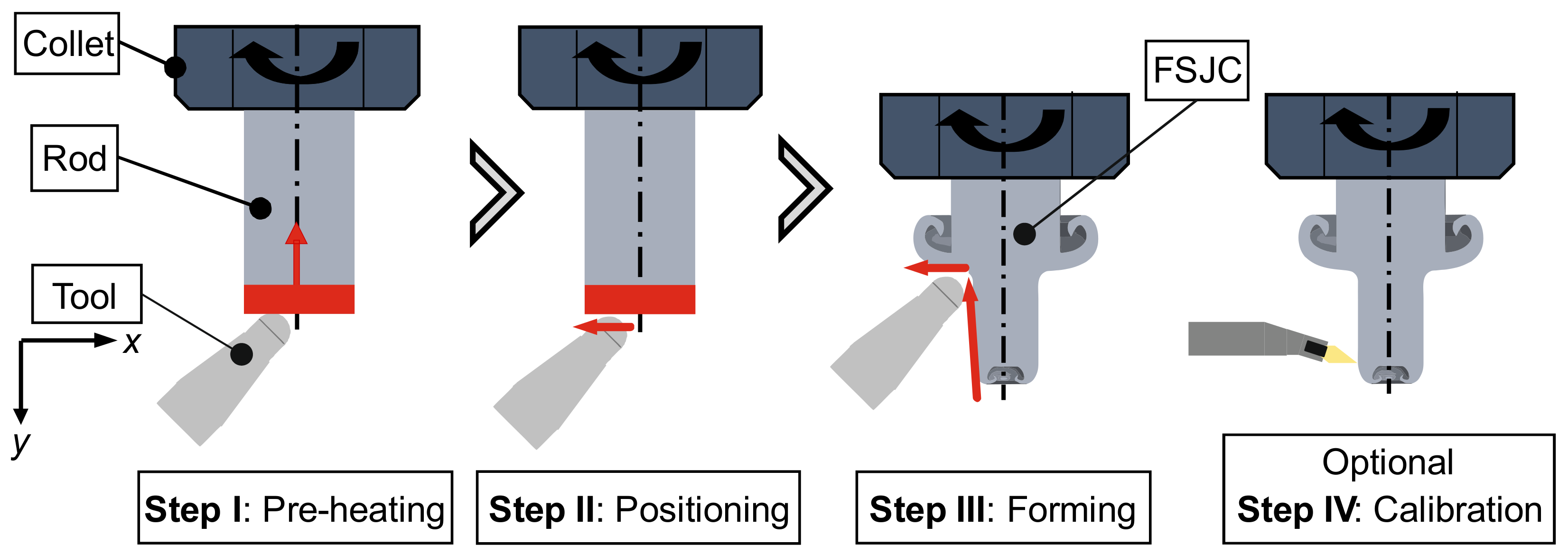
The central features of the first process stage are described below based on the four sub-steps of this process stage, shown in Figure 1. The raw semi-finished product is a cylindrical bar section of a round rod with a diameter of d = 8 mm and a length of l = 55 mm. At the beginning, the rod is inserted into the collet of a spindle and set in rotation. The spindle is a horizontally arranged milling spindle from the manufacturer Weiss (Maroldsweisach, Germany) with a maximum rotational speed of nmax = 15,000 rpm.
The first substep in the production of the FSJCs is the friction-induced preheating of the steel round bar through frictional contact of the rotating round bar with the KX 40 carbide tool, containing 9 wt% cobalt (Co) and 91 wt% tungsten carbide (WC). The contact surface of the carbide tool consists of a cylinder with a diameter of d = 3 mm and a tip radius of r = 1.5 mm. To produce a wide variety of geometries, the carbide tool is attached to a cross support, which allows the tool to be moved continuously to the x and y coordinates shown in Figure 1. After heating the round bar section, the tool is briefly positioned before the desired geometry of the FSJC is formed based on a path curve. For all investigations, the forming process takes place at a constant bar rotational speed of n = 12,000 rpm and a feed rate of f = 50 mm/min. In the final process step, a conventional turning process is used to eliminate minor geometric deviations in the diameter of the FSJC produced and to set a uniform diameter of d1 = 5.5 mm.
Second process stage: Joining process.
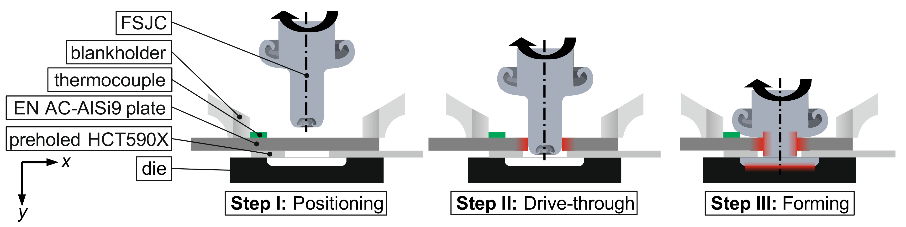
In the investigations, two sheets of different material (length in each case l = 105 mm and width b = 45 mm) are joined with the previously produced FSJC in the second process stage. The sheets overlap by Δl = 16 mm, and the joint is positioned centrally. With the multiphase steel HCT590X and the aluminium cast sheet of the alloy AlSi9, which is produced by sand casting, two sheets with very different strengths are combined. Due to the significantly higher strength of the steel sheet, a pre-hole with a diameter of d = 6 mm is provided in advance of the joining process. In the joining process, the FSJC-side aluminium cast sheet, which has no pre-hole (analogous to flow drilling), is driven through (see Figure 2). The FSJC produced in the previous process step from the round bar of the steel material C45e has a significantly higher mechanical and temperature strength compared to the aluminium cast plate. This allows the aluminium cast plate to be driven through, which avoids the need for a pre-drill hole. When the FSJC is driven through the cast aluminium plate, heat is generated, which is used to reduce the flow stress of the cast aluminium plate and, thus, to reduce the process forces as well as the tool loads. The FSJC, which is heated by the drive-through, continues in the negative y-direction so that it subsequently comes into frictional contact with the matrix underneath, which leads to further strong frictional heat generation. The material volume of the FSJC, which is also reduced in its strength by this frictional contact, flows laterally and fills the die completely, forming the closing head necessary for the high strength of the joint. After reaching the end position, both the feed and the rotation speed are stopped, and the joint is removed.
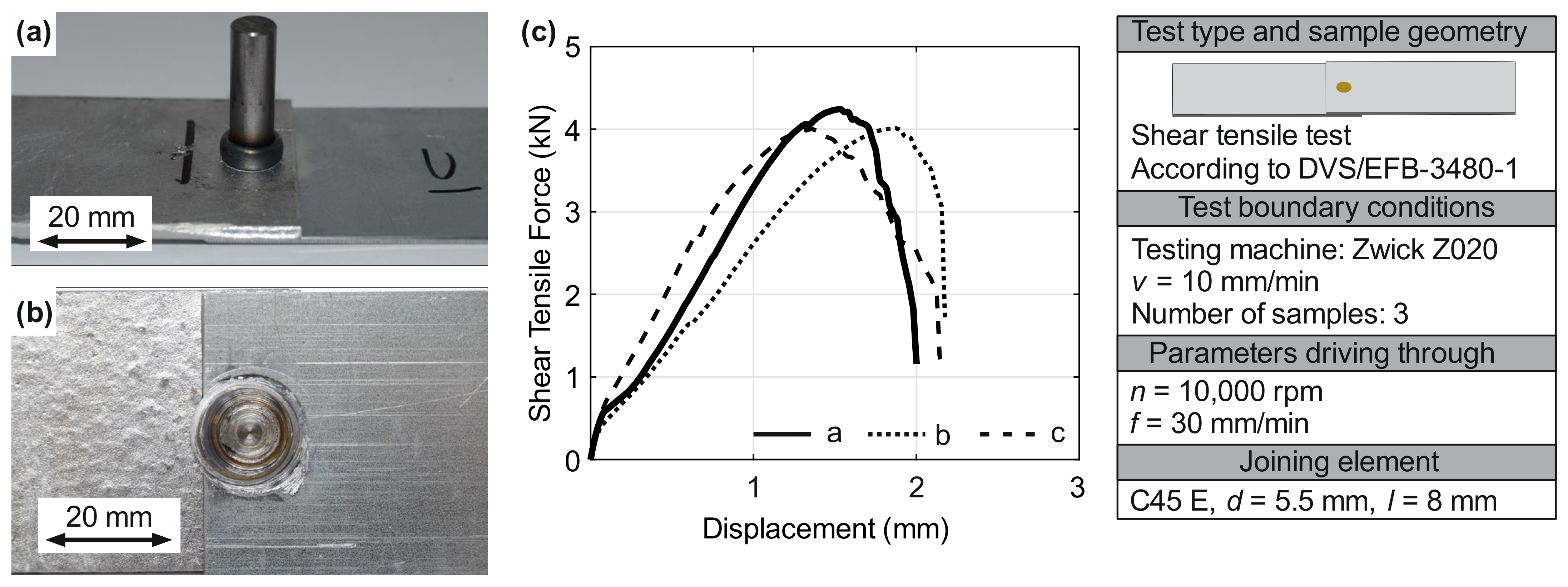
The central object is to determine the influence of the thermomechanical joining process on the challenge of mechanical joining of cast sheets described in the introduction and whether they can be solved. Due to this research question, the focus is on the second process stage of the joining process, and therefore, uniform auxiliary joining elements with the previously described specifications and production conditions are used. In the second process stage, the process step of drive-through the aluminium cast sheets is varied in a two-stage experimental plan (low/high) in a wide interval. For the rotational speed, the two stages of n = 2000 rpm and n = 10,000 rpm, and for the feed, two stages of f = 30 mm/min and f = 150 mm/min are considered. To characterise the influence of the change in rotational speed as well as the feed rate during the drive-through on the process variables (such as the temperature or the force) as well as the properties of the joined component, various measuring and testing methods are used, which are described in the following. The forces that occur during the drive-through and the joining process are recorded employing a strain gauge force transducer K6D175 50 kN/5 kNm/UP13 (ME-Meßsysteme GmbH, Hennigsdorf, Germany) and processed further with a measuring amplifier QuantumX Module MX440B (Hottinger Brüel and Kjaer GmbH, Göttingen, Germany). Non-contact temperature measurement with a thermographic camera is not possible here due to the optical properties of the aluminium. However, to capture a qualitative impression of the different heat development of the drive-through and the forming (depending on the rotational speed and feed used), a type K thermocouple G/G-24-KK-IEC (Therma Thermofühler GmbH, Lindlar, Germany) is used at a distance of Δl ≈ 12 mm from the joint. Processing of the measurement signal is carried out with the measurement amplifier described above. The previously characterised tooling system, in conjunction with the position and alignment of the sheets, is used to directly produce shear tensile specimens. These joints are then tested according to the standard [29] DVS/EFB-3480-1: testing the properties of mechanical and hybrid (mechanical/bonded) joints, which applies to the testing of steel and non-ferrous metals up to a thickness of t ≤ 4.5 mm.
2.2. Manufacture and Properties of Cast Sheets
The alloy utilized in this research was EN AC-AlSi9 (i.e., European Norm—aluminium cast product), a hypoeutectic aluminium casting alloy. Its exceptional castability makes it highly suitable for sand casting procedures, particularly when manufacturing thin-walled structures. Furthermore, the supplier TRIMET (Essen, Germany) previously implemented a long-term refining process with Sr to enhance the mechanical properties of the aluminium alloy [30].
For the presented investigations, aluminium cast sheets with a thickness of t = 2 mm were considered, which were produced using the sand casting process. The moulding material was quartz sand H33, characterised by an average grain size of 260 µm, mixed with the cold-curing resin system “Pentex L” (Hüttenes Albertus, Düsseldorf, Germany). The cold-curing resin system consists of the resin (Pentex L 8338) and the activator (Pentex L 6576) mixed in a 1:1 ratio, equivalent to 120 g of each. The ratio of quartz sand to the cold-curing system was 0.5 wt %. To prevent the aluminium melt from penetrating the moulding material, a coating based on zirconium silicate (Zirkofluid 3139 KBV) with isopropanol as a carrier liquid was applied to the sand-casting mould. The coating thickness was measured between 250 µm and 300 µm using a thickness gauge according to ISO 2808 [31]. The viscosity to be achieved was determined according to DIN 53211 using a 4 mm DIN flow cup, also known as a Ford flow cup, with a run-out time of 15 s. After 3 min of brief drying time, any residual isopropanol was burned off. Following this sequence of procedures, all moulds were built, lined up vertically, and braced with a special steel frame following the work of Neuser et al. [32].
For the manufacturing of the aluminium cast sheet with the dimensions 240 mm × 120 mm, 2.5 kg of aluminium was melted in a graphite crucible using a resistance furnace at a temperature of 720 °C. To clean the melt, 12 g of the nitrogen-based cleaning agent Degasal (Schäfer Metallurgie GmbH, Hennef, Germany) was applied. The cleaning agent was applied to the surface of the melt and inserted into the melt through a dipping bell. After an exposure time of 4 min, the dipping bell, as well as the slag, were removed. Subsequently, the melt was poured off as quickly as possible.
A Bruker Q4 Tasman (Bruker AXS GmbH, Karlsruhe, Germany) optical emission spectroscope (OES) was used to determine the chemical composition of EN AC-AlSi9. The chemical composition was measured after the casting trials. The principle of operation of the OES can be described in a very simplified way, as follows. Upon exposure to an electric spark, the specimen vaporizes and partially ionizes, resulting in the emission of electromagnetic radiation. Excited atoms emit a characteristic radiation that is assigned to the respective elements. The measurement is carried out according to DIN EN 14726. Therefore, a specimen for the chemical analysis is extracted during each trial. These measurements are necessary for a more detailed analysis of the microstructure later. Table 1 summarises the chemical composition of AlSi9 measured by OES.
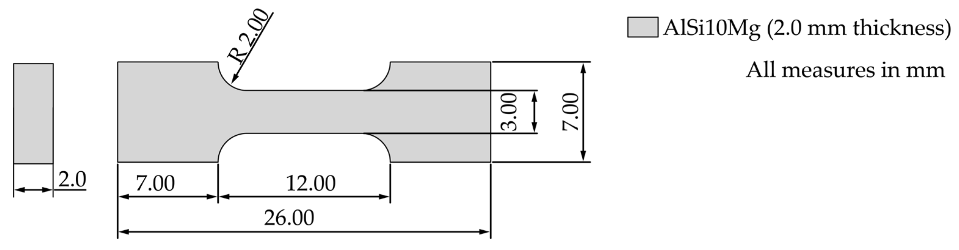
The mechanical characterisation of the manufactured aluminium plates was performed employing tensile tests according to DIN EN ISO 6892-1 and Brinell hardness tests according to DIN EN ISO 6506-1. Figure 3 illustrates the geometry of tensile specimens illustrated. These tensile tests were carried out on the MTS tabletop tensile testing machine at a test rate of 1.5 mm/min, with a clamping pressure of 8 MPa. The data were recorded at a rate of 1024 Hz.
The hardness test specimens were ground in advance with 1200-grit sandpaper. The Brinell hardness test was carried out on the Frankoskop hardness tester (Franke, Aalen, Germany) at a test force of 62.5 kp. A tungsten carbide ball with a diameter of 2.5 mm was used to apply the test force for 10 to 15 s following the standard.
Table 2 provides the mechanical properties of AlSi9 for a casting thickness of t = 2 mm. This also includes the yield strength ratio, which is the quotient of yield strength and tensile strength. The DVS 3420 (Clinching) guideline specifies a limit value of 0.70 as the yield strength ratio; if the determined value is lower, the joint is considered suitable for clinching [33]. This value is applied in this study as a reference value.
2.3. Investigations of the Microstructure
In preparation for the light microscopic (LM) examinations as well as the EBSD analysis, the joined specimens were embedded in the embedding agent CEM1000 blue (Cloeren Technology GmbH, Wegberg, Germany) and ground with a grain size of up to 4000. The samples were subsequently polished for 24 h with an automatic polishing machine using the polishing agent Silica Suspension (Cloeren Technology, Wegberg, Germany), which contains nanoparticles with a size of 50 nm. LM images were taken with the Keyence VHX5000 digital microscope. In addition, EBSD images were taken with the Zeiss Ultra Plus Scanning Electron Microscope (SEM) to investigate the microstructure. For this application, a magnification of 500 was used at a working distance of 13.5 mm and a step size of 0.15.
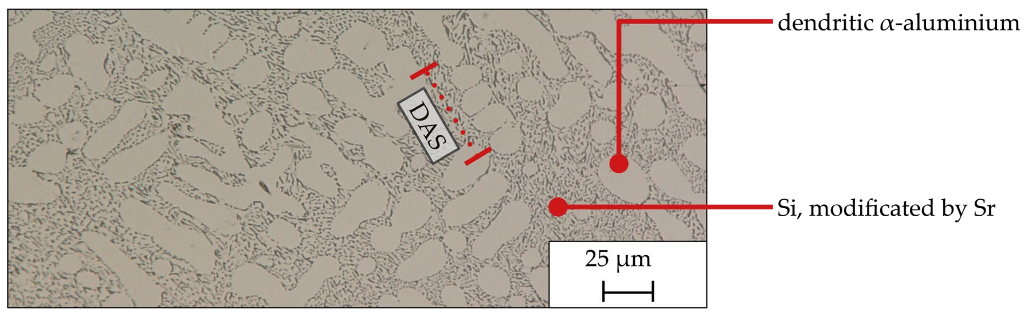
According to the BDG Guideline P220, the secondary dendrite arm spacing (DAS) was measured [34]. For this application, specimens were taken from the centre of the cast sheets and prepared for LM investigations as described above. The examination area always refers to the cross-sectional area. Based on the P220 guideline, at least 10 different dendrite stems were analysed per specimen. The calculation of the DAS is based on Equation (1).
The DAS can be determined from the measured length of a dendrite stem and the number of dendrites. The DAS allows conclusions to be drawn regarding the solidification conditions and the mechanical properties. The smaller the DAS, the higher the corresponding mechanical properties [14]. The latter has a major influence on the suitability for joining and the load-bearing capacity of a joint.
3. Results
The explanation of the results described below is divided into three sections. First, the findings from the influence of the process parameters on the joining process itself are explained. This is followed by a characterisation of the strength of the joint. The third aspect is the modified microstructure based on the thermomechanical forming process.
3.1. Characteristics and Properties of the Joining Process
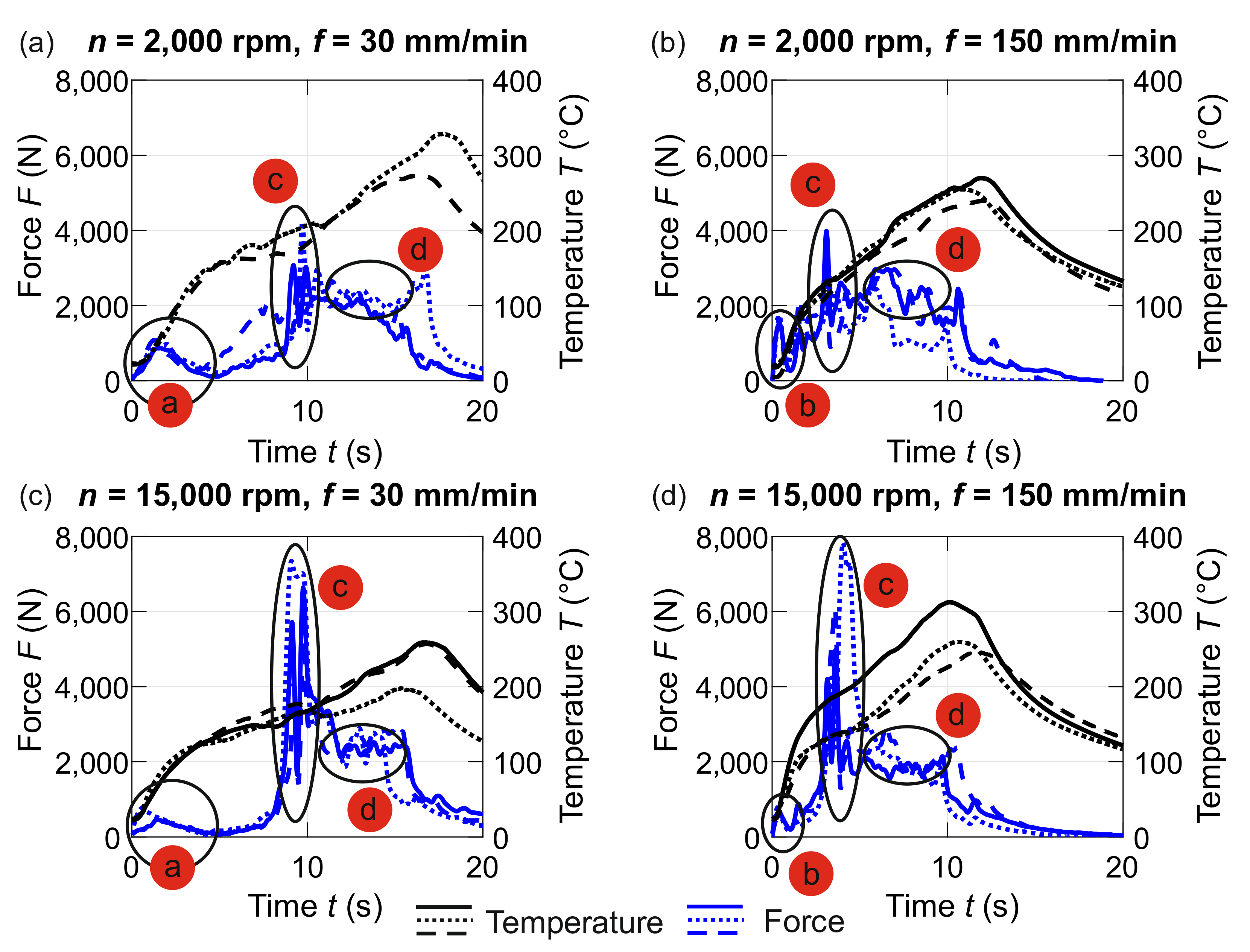
By varying the rotational speed as well as the feed rate, two key parameters of the processing time and the heat input are influenced in addition to the process forces for the innovative joining process. A higher feed rate can significantly reduce the processing time and, thus, increase the number of joining points per time. Using a higher rotational speed, more kinetic energy is introduced into the process, which enables the generation of a higher amount of heat. This higher heat quantity can have a positive influence on both the joining partners and the microstructure so that, for example, the deformation resistance in the form of yield stress is reduced. The feasibility of the two process route changes described needs to be validated, and the interdependencies with the other process variables (such as the process forces) must be assessed. Figure 4 shows the influence of rotational speed and feed rate on the process variables of the thermomechanical joining process in the form of the joining force (positive y-direction, Figure 2) as well as the external sheet temperature of the cast sheet at a distance of Δl ≈ 12 mm from the centre of the joint. For each of the parameter combinations of feed and rotational speed presented, the temperature curves (black) and force curves (blue) of three identical tests are shown (except for the parameter combination with the rotational speed of n = 2000 rpm and f = 30 mm/min, where two temperature records are depicted). The time t = 0 s represents the point of contact between the steel auxiliary joining element and the cast aluminium sheet for all courses. Despite smaller deviations within an examination point, individual process phases are highlighted across parameters, and influences on the process introduced by the feed and rotational speed can also be identified in a direct comparison of the different parameters. The individual process phases and effects are assigned letters in the figure, which are explained and characterised in the following list.
- (a)
- For the drive-through of the aluminium cast sheet at a low feed rate of f = 30 mm/min, an increase in the process force can be seen until a local maximum is reached. The duration of the total drive-through of the aluminium cast sheet is td = 4 s at this feed rate. Even before forces that are almost back to zero at the total time of t = 4 s are reached, a clear flattening of the process force can be seen for both parameter combinations with the low feed rate. This drop in the process force can be explained by the softening of the aluminium cast sheet due to the application of frictional heat. The height of the local maximum of the process force is influenced by the rotational speed. For the low rotational speed of n = 2000 rpm, a significantly higher force is determined with Fmax = 1120 N (standard deviation SD = 48 N) compared to the characteristic value of Fmax = 638 N (SD = 107 N) for the higher rotational speed of n = 10,000 rpm. Regarding the friction-induced application of temperature based on the drive-through process, no difference can be determined.
- (b)
- As expected, the drive-through of the aluminium sheet using the significantly higher feed rate of f = 150 mm/min compared to the previous observation leads to a significantly shorter partial process time of drive-through of only td = 0.8 s. Independently of this, a comparable course of the force curve occurs with a local maximum being reached and a final decrease in the force due to the temperature-based softening of the cast sheet. Both the increase and the decrease in temperature occur more quickly due to the significantly shorter process time of drive-through. It is also observed for the high feed rate that the maximum force at low rotational speed with Fmax = 1705 N (SD = 106 N) is significantly higher compared to the high rotational speed with Fmax = 701 N (SD = 113 N). The qualitative comparison of the temperature curves for the high feed rate, as well as the high and low rotational speed, reveals the tendency that more heat is generated when both parameters are high. However, this is a tendency and requires further investigation. Based on these two aspects, it can be concluded that the processing time can be significantly reduced with a higher feed rate, but this is also associated with a higher power requirement.
- (c)
- Following the drive-through (with the local force maximum), the auxiliary joining element is guided through the pre-punched steel sheet for all test points with a constant feed rate compared to the drive-through. Here, due to the pre-punching, no new frictional contact occurs (except for the remaining frictional contact at the residual points of the cast sheet), which explains the flattening of the force curve. At time t ≈ 9 s (for the feed of f = 30 mm/min) and t ≈ 3 s (for the feed of f = 150 mm/min), the front shaft of the auxiliary joining element reaches the bottom of the die. This frictional contact occurring over the entire cross-sectional area of the auxiliary joining element with the die (d = 14 mm) leads to a strong increase in the joining force. This increase is strongly dependent on the rotational speed; the examination points with a high rotational speed lead to significantly higher maximum forces. One reason for the higher forces is the higher friction path that increases with rotational speed.
- (d)
- During the forming of the closing head, an almost constant force level of F ≈ 2000 N is achieved for all test points (apart from some fluctuations in the range of a few percentage points), which is independent of the process parameters of the previous drive-through. The average force of the forming of the closing head is thus independent of the process parameters of the previous drive-through. Due to the identical process parameters during the forming process, this process phase also has an identical duration. A significant influence of the process parameters of the previous phase (drive-through of the cast sheet) on the temperature level in the process of forming the closing head cannot be determined either. The constant temperature level for all investigations may also be an explanation for the comparable process forces. Process forces during the forming of the closing head with identical process parameters and geometry are, therefore, only influenced by the strength of the FSJC. The softening of the FJSC that occurs during the application of heat is, therefore, comparable and independent of the drive-through. In future investigations, it will be necessary to vary the process parameters during the forming process to identify any interactions with the drive-through and to determine specific possibilities for influencing the process temperature.Figure 4. Influence of rotational speed and feed rate during the drive-through of the cast sheet on the joining force as well as the temperature. (a) low rotational speed and feed, (b) low rotational speed and high feed, (c) high rotational speed and low feed, (d) high rotational speed and feed.Figure 4. Influence of rotational speed and feed rate during the drive-through of the cast sheet on the joining force as well as the temperature. (a) low rotational speed and feed, (b) low rotational speed and high feed, (c) high rotational speed and low feed, (d) high rotational speed and feed.
![Jmmp 07 00169 g004]()

3.2. Characteristics of the Joint Connections
In addition to considering the influence of different process parameters on the joining process, it is also important to investigate the influence of the use of the process parameters and the casting alloy on the joint connection itself. An example of a joined connection (parameters when driving through the cast sheet n = 2,000 rpm and f = 150 mm/min is shown in Figure 5a). In both the side view and the view of the closing head (Figure 5b), it can be concluded from the tempering colours of the steel auxiliary joining element that a considerable amount of heat is generated during the joining process. The results of the mechanical testing of three shear tensile specimens for the high rotational speed of n = 10,000 rpm and the low feed rate f = 30 mm/min for drive-through are shown in Figure 5c. For this parameter combination, the maximum force (Fmax), as well as the displacement to reach the maximum force (smax), exhibit good correspondence with a mean value of Fmax = 4.1 kN (SD = 0.1 kN) and smax = 1.6 mm (SD = 0.2 mm). A change in the parameters during the drive-through of the cast aluminium sheet shows no statistically significant influence on the maximum forces as well as the displacement when the maximum force is reached. The maximum forces in the shear tensile test before the failure of the connections are between Fmax = 3.3 kN and Fmax = 5.2 kN. An explanation for this can be the fact that the parameters used to form the locking head are not changed. Furthermore, the failure mechanism for all tested connections is the pull-out of the cast plate. Due to the non-existing (significant) differences in the maximum force as well as the displacement, the thermomechanical drive-through of the cast plates (which represent the failure point of the connection) may not have caused any modification of the mechanical properties of the cast plates that is dependent on the parameters of the drive-through.
3.3. Macroscopic Examination
The DAS is measured for the present samples with a mean value of 14.7 µm and a standard deviation of 2.5 µm. Compared to similarly produced samples from Neuser et al. [32], almost identical DAS could also be achieved. An example of a DAS measurement is illustrated in Figure 6. The solidification conditions have a decisive influence on the subsequent mechanical properties, in particular, on the subsequent joining behaviour, where above all, the elongation at fracture and the quotient of yield strength and tensile strength (yield strength ratio) are of decisive importance. The yield strength ratio can be quantified as 0.41 from the determined mechanical characteristic values. In the DVS 3420 guideline for clinching (German Welding Society), a yield strength ratio of less than 0.7 is assumed for a material suitable for clinching [33]. With the mechanical parameters determined and the resulting solidification conditions, it can be assumed that the material is suitable for joining based on guideline 3420. Furthermore, the joint images in Figure 5 show that no cracks are induced during the joining process. Since this guideline is a limit value for clinching, in which a joint is made mechanically, and in the case of adaptive friction joining used in this study, a high degree of forming is achieved through thermomechanical forming of the joint, but the forming forces can be kept low compared to clinching. As shown in Figure 4, significantly lower values are achieved over the entire joining process compared to a clinching process; here, it is approximately 40 kN.
The alloy AlSi9 used in this study was refined with Sr (see Table 1). As a result, the Si is not plate-like but lamellar, as shown in Figure 6. This allows the mechanical properties to be increased, as the coarse Si flakes then act as crack initiators. The lamellar morphology avoids this. Since the mechanical joinability goes hand in hand with the microstructure, the joinability of the alloy also increases.
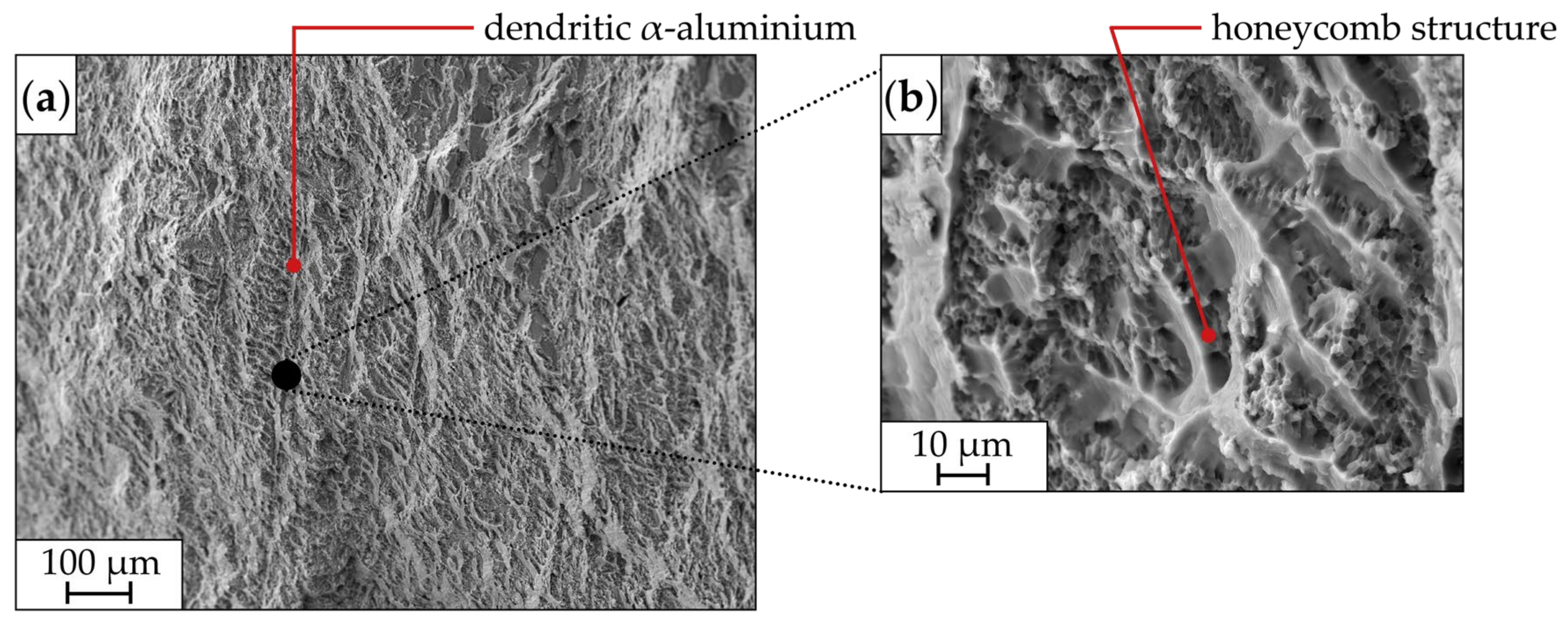
Figure 7 highlights a fracture surface of the AlSi9. On the left side in (a), the dendritic solidification morphology of AlSi9 can be seen in the fracture surface. The right figure (b) shows the 1000× magnification of the marked dendritic structure. In this magnification, it can be seen that the fracture surface has a honeycomb structure. This indicates that ductile failure has occurred in the specimen. Such ductile failure behaviour is caused by the addition of Sr as a refining agent, as shown in Figure 6, because one of the effects is an increase in elongation at fracture. High ductility of the material is important, on the one hand, for the actual joining process to be able to realise high degrees of deformation and, on the other hand, to be able to absorb high energy in later load-bearing capacity tests (see Figure 5).
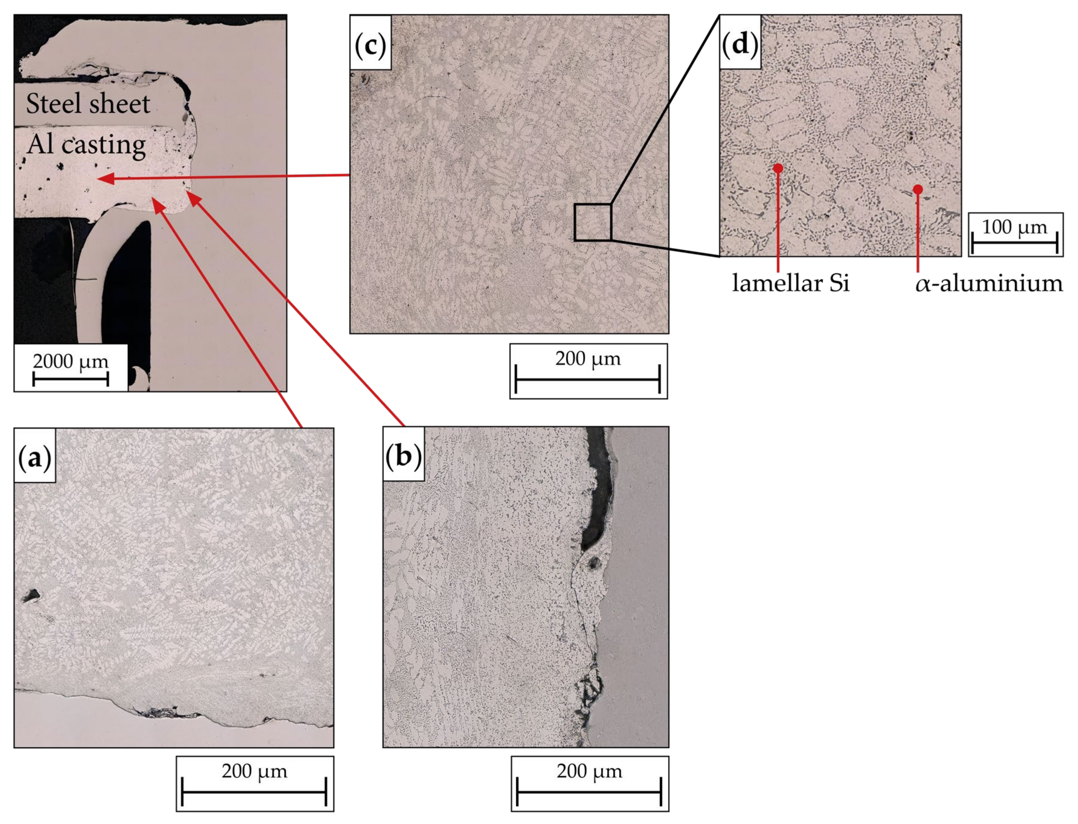
In the scope of the investigations, LM images of the cross-section of the AlSi9 and HCT590X plates joined using frictional forces were obtained. Figure 8 illustrates such an image. The configuration of the joint was as follows: the steel sheet HCT590X was presented on the die side, while the AlSi9 cast plate was on the punch side. In the forming area of the AlSi9 cast plate, the dendritic microstructure in the die-side edge area (a) exhibited a remarkably fine Si eutectic formation due to partial remelting. Moreover, the joining process led to the formation of dendritic α-aluminium with a distinctive stem-like morphology, which can be seen in the LM image (b). The exemplary image (c) from the middle of the specimen reveals the characteristic microstructure of AlSi9. Here (magnified image (d)), no change due to the thermally induced friction process can be seen, also in comparison with Figure 5. An intriguing aspect of the frictional joining process was the absence of crack initiation in the cast plate, a common issue with conventional mechanical joining methods [35].
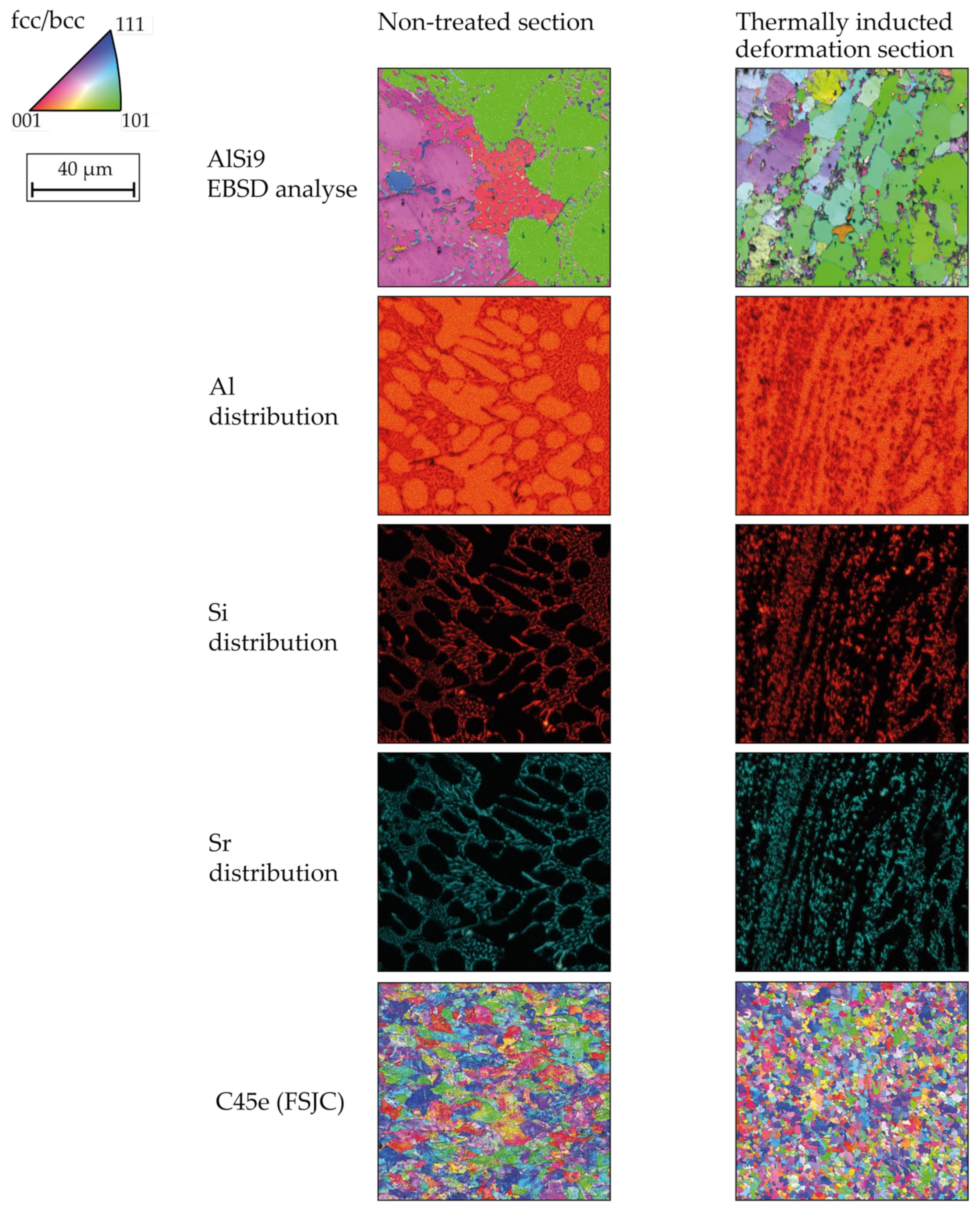
The deformation process at the joint and in the non-deformation-induced area is highlighted in Figure 9 using EBSD images. In addition, EBSD images of the as-cast condition and the heat-treated condition are shown as references. The forming process, coupled with partial melting, induces grain refinement in AlSi9. In the base material (AlSi9), larger grains are noticeable, which is a characteristic microstructure for sand casting. In the cross-section, it can be seen that there is a grain orientation caused by solidification. Conversely, in the heat-affected zone (HAZ), a finer microstructure is observed, and the forming process leads to an alteration in grain orientation. The FSJCs material C45e undergoes recrystallization due to the previous forming and thermal influence, resulting in significantly smaller grains. Comparing the two EBSD images highlights the evident differences in grain size between the forming zone and the as-cast condition, offering insights into the effects of the forming process on the microstructure of AlSi9 and C45e materials.
4. Conclusions
This paper presents investigations to solve the current state-of-the-art challenges of the versatile joining of cast aluminium alloys. For this purpose, a combination of the thermomechanical joining process and hypoeutectic aluminium cast plates is used in order to use the heat generated in the joining process for damage-free joining and to adapt the mechanical properties of the casting alloy to the joining process. The key findings of the publication are:
- The pre-hole-free joining of the aluminium cast plates produced employing sand casting is possible irrespective of the parameters of the joining process examined.
- All examined joints show good strength in the shear tensile test.
- Driving through the aluminium cast plates (AlSi9) applies a sufficiently high amount of heat so that no cracks appear in the casting.
- The heat applied, combined with the associated partial melting, leads to significant grain refinement due to the recrystallisation that takes place.
Author Contributions
Conceptualization, T.B. and M.N.; methodology, T.B. and M.N.; validation, T.B. and M.N.; investigation, T.B. and M.N.; data curation, T.B. and M.N.; writing—original draft preparation, T.B. and M.N.; writing—review and editing, T.B., M.N., K.-P.H., W.H. and M.S.; supervision, W.H. and M.S.; project administration, W.H. and M.S.; funding acquisition, W.H. and M.S. All authors have read and agreed to the published version of the manuscript.
Funding
Funded by the Deutsche Forschungsgemeinschaft (DFG, German Research Foundation)—TRR 285/2—418701707. The authors thank the German Research Foundation for their organizational and financial support.
Data Availability Statement
The data presented in this study are available on request from the corresponding author at www.trr285.de.
Acknowledgments
Furthermore, the authors would like to take this opportunity to thank Christian Wischer, Paderborn University, Lea Kaspersmeier, Oliver Hornberger, and Moritz Klöckner, Chair of Materials Science at Paderborn University, for their support in the preparation and conduction of casting trials as well as thermomechanical joining and evaluation.
Conflicts of Interest
The authors declare no conflict of interest.
References
- Cai, W.; Lai, K.-H.; Liu, C.; Wei, F.; Ma, M.; Jia, S.; Jiang, Z.; Lv, L. Promoting sustainability of manufacturing industry through the lean energy-saving and emission-reduction strategy. Sci. Total Environ. 2019, 665, 23–32. [Google Scholar] [CrossRef] [PubMed]
- Rosenthal, S.; Maaß, F.; Kamaliev, M.; Hahn, M.; Gies, S.; Tekkaya, A.E. Lightweight in Automotive Components by Forming Technology. Automot. Innov. 2020, 3, 195–209. [Google Scholar] [CrossRef]
- Buberger, J.; Kersten, A.; Kuder, M.; Eckerle, R.; Weyh, T.; Thiringer, T. Total CO2-equivalent life-cycle emissions from commercially available passenger cars. Renew. Sustain. Energy Rev. 2022, 159, 112158. [Google Scholar] [CrossRef]
- Taub, A.; de Moor, E.; Luo, A.; Matlock, D.K.; Speer, J.G.; Vaidya, U. Materials for Automotive Lightweighting. Annu. Rev. Mater. Res. 2019, 49, 327–359. [Google Scholar] [CrossRef]
- Haghshenas, M.; Gerlich, A.P. Joining of automotive sheet materials by friction-based welding methods: A review. Eng. Sci. Technol. Int. J. 2018, 21, 130–148. [Google Scholar] [CrossRef]
- Sarfraz, M.S.; Hong, H.; Kim, S.S. Recent developments in the manufacturing technologies of composite components and their cost-effectiveness in the automotive industry: A review study. Compos. Struct. 2021, 266, 113864. [Google Scholar] [CrossRef]
- Salonitis, K.; Jolly, M.; Pagone, E.; Papanikolaou, M. Life-Cycle and Energy Assessment of Automotive Component Manufacturing: The Dilemma Between Aluminum and Cast Iron. Energies 2019, 12, 2557. [Google Scholar] [CrossRef]
- Graf, A. Aluminum alloys for lightweight automotive structures. In Materials, Design and Manufacturing for Lightweight Vehicles, Chapter 3; Elsevier: Amsterdam, The Netherlands; Woodhead Publishing: Duxford, UK, 2021; pp. 97–123. ISBN 9780128187128. [Google Scholar]
- Kurt, H.I.; Oduncuoglu, M.; Asmatulu, R. Wear Behavior of Aluminum Matrix Hybrid Composites Fabricated through Friction Stir Welding Process. J. Iron Steel Res. Int. 2016, 23, 1119–1126. [Google Scholar] [CrossRef]
- Kunčická, L.; Kocich, R. Optimizing electric conductivity of innovative Al-Cu laminated composites via thermomechanical treatment. Mater. Des. 2022, 215, 110441. [Google Scholar] [CrossRef]
- Kunčická, L.; Kocich, R. Effect of activated slip systems on dynamic recrystallization during rotary swaging of electro-conductive Al-Cu composites. Mater. Lett. 2022, 321, 132436. [Google Scholar] [CrossRef]
- Meschut, G.; Merklein, M.; Brosius, A.; Drummer, D.; Fratini, L.; Füssel, U.; Gude, M.; Homberg, W.; Martins, P.; Bobbert, M.; et al. Review on mechanical joining by plastic deformation. J. Adv. Join. Process. 2022, 5, 100113. [Google Scholar] [CrossRef]
- Machuta, J.; Nová, I.; Kejzlar, P. Structure and Mechanical Properties of Aluminium Alloys AlSi10 and AlSi5Mg. Manuf. Technol. 2017, 17, 772–777. [Google Scholar] [CrossRef]
- Kaufman, J.G.; Rooy, E.L. Aluminum Alloy Castings: Properties, Processes, and Applications; ASM International: Materials Park, OH, USA, 2004; ISBN 978-0-87170-803-8. [Google Scholar]
- Martinsen, K.; Hu, S.J.; Carlson, B.E. Joining of dissimilar materials. CIRP Ann. 2015, 64, 679–699. [Google Scholar] [CrossRef]
- Di Michele, G.; Guglielmi, P.; Palumbo, G.; Sorgente, D. Investigation on the Strain Behaviour of a Precipitation-Hardenable Aluminium Alloy through a Temperature Gradient Based Heat Treatment. KEM 2015, 639, 361–368. [Google Scholar] [CrossRef]
- Warlimont, H.; Martienssen, W. (Eds.) Springer Handbook of Materials Data, 2nd ed.; Springer International Publishing: Cham, Switzerland, 2018; ISBN 9783319697437. [Google Scholar]
- Lambiase, F.; Scipioni, S.I.; Lee, C.-J.; Ko, D.-C.; Liu, F. A State-of-the-Art Review on Advanced Joining Processes for Metal-Composite and Metal-Polymer Hybrid Structures. Materials 2021, 14, 1890. [Google Scholar] [CrossRef]
- Siret, O.; Desrayaud, C.; Tourabi, M.A. Thermomechanical Joining of Aluminium Alloys: Effects of the Shear on the Quality of the Joining. MSF 2010, 638–642, 3716–3721. [Google Scholar] [CrossRef]
- Haribalaji, V.; Boopathi, S.; Mohammed Asif, M. Optimization of friction stir welding process to join dissimilar AA2014 and AA7075 aluminum alloys. Mater. Today Proc. 2022, 50, 2227–2234. [Google Scholar] [CrossRef]
- Çam, G.; Mistikoglu, S. Recent Developments in Friction Stir Welding of Al-alloys. J. Mater. Eng. Perform. 2014, 23, 1936–1953. [Google Scholar] [CrossRef]
- Min, J.; Li, J.; Li, Y.; Carlson, B.E.; Lin, J.; Wang, W.-M. Friction stir blind riveting for aluminum alloy sheets. J. Mater. Process. Technol. 2015, 215, 20–29. [Google Scholar] [CrossRef]
- Costas, M.; Morin, D.; Sønstabø, J.K.; Langseth, M. On the effect of pilot holes on the mechanical behaviour of flow-drill screw joints. Experimental tests and mesoscale numerical simulations. J. Mater. Process. Technol. 2021, 294, 117133. [Google Scholar] [CrossRef]
- Altvater, S.; Sikora, S.P.; Siefkes, T. Transition between flow-drill screwing systems considering joining process and joint characteristics. Adv. Ind. Manuf. Eng. 2022, 5, 100091. [Google Scholar] [CrossRef]
- Aslan, F.; Langlois, L.; Balan, T. Experimental analysis of the flow drill screw driving process. Int. J. Adv. Manuf. Technol. 2019, 104, 2377–2388. [Google Scholar] [CrossRef]
- Wischer, C.; Homberg, W. A contribution on versatile process chains: Joining with adaptive joining elements, formed by friction spinning. Prod. Eng. Res. Devel. 2022, 16, 379–388. [Google Scholar] [CrossRef]
- Wischer, C.; Homberg, W. Further Development of an Adaptive Joining Technique Based on Friction Spinning to Produce Pre-Hole-Free Joints. KEM 2022, 926, 1468–1478. [Google Scholar] [CrossRef]
- Borgert, T.; Neuser, M.; Wiens, E.; Grydin, O.; Homberg, W.; Schaper, M. Influence of thermo-mechanical joining process on the microstructure of a hypoeutectic aluminium cast alloy. In Sheet Metal 2023; Materials Research Forum LLC: Millersville, PA, USA, 2023; pp. 187–194. [Google Scholar]
- DVS/EFB-3480-1; Testing the Properties of Mechanical and Hybrid (Mechanical/Bonded) Joints. Beuth: Berlin, Germany, 2017.
- Trimet Aluminium SE. Trimal-37: Druckgusslegierung für Duktile Anwendungen (Engl. Die Casting Alloy for Ductile Applications). Available online: https://www.trimet.eu/fileadmin/downloads/de/trimal-produktblaetter/produktblatt_trimal-37_ASI_2020.pdf (accessed on 17 August 2020).
- CEN: EN ISO 2808:2019; Paints and Varnishes—Determination of Film Thickness. European Committee for Standardization: Brussels, Belgium, 2019.
- Neuser, M.; Böhnke, M.; Grydin, O.; Bobbert, M.; Schaper, M.; Meschut, G. Influence of heat treatment on the suitability for clinching of the aluminium casting alloy AlSi9. Proc. Inst. Mech. Eng. Part L J. Mater. Des. Appl. 2022, 236, 1246–1257. [Google Scholar] [CrossRef]
- DVS Media GmbH. DVS/EFB Merkblatt DVS/EFB 3420, Clinchen-Überblick, Clinching-Basics; DVS Media GmbH: Düsseldorf, Germany, 2002. [Google Scholar]
- BDG-Bundesverband der Deutschen Gießerei-Industrie. P220-Bestimmung des Dendritenarmabstandes für Gussstücke aus Aluminium-Gusslegierungen. Available online: https://www.guss.de/fileadmin/user_upload/richtlinien/bdg-richtlinie_p_220.pdf (accessed on 17 August 2020).
- Neuser, M.; Grydin, O.; Andreiev, A.; Schaper, M. Effect of Solidification Rates at Sand Casting on the Mechanical Joinability of a Cast Aluminium Alloy. Metals 2021, 11, 1304. [Google Scholar] [CrossRef]
Figure 1.
Principle of the first process stage to produce FSJCs according to [28].
Figure 1.
Principle of the first process stage to produce FSJCs according to [28].

Figure 2.
Principle of the second process stage, joining of two sheets according to [28].
Figure 2.
Principle of the second process stage, joining of two sheets according to [28].

Figure 3.
Dimensions of a tensile test specimen.

Figure 5.
Mechanical testing of the joint, (a) joint before testing, (b) closing head, (c) results of three specimens for the process parameters of the drive-through of n = 10,000 rpm and f = 30 mm/min.
Figure 5.
Mechanical testing of the joint, (a) joint before testing, (b) closing head, (c) results of three specimens for the process parameters of the drive-through of n = 10,000 rpm and f = 30 mm/min.

Figure 6.
Cross-section LM image of AlSi9 in the as-cast condition.

Figure 7.
A fractured section of a tensile specimen taken by scanning electron microscopy (SEM). (a) magnification of 100; (b) magnification of 1000.
Figure 7.
A fractured section of a tensile specimen taken by scanning electron microscopy (SEM). (a) magnification of 100; (b) magnification of 1000.

Figure 8.
LM image of a joint, cross-section view. Die-sided HCT590X and punch-sided AlSi9. (a) die-side edge area, (b) neck area of the FSJC, (c) middle of the cast plate, (d) magnification of image (c).
Figure 8.
LM image of a joint, cross-section view. Die-sided HCT590X and punch-sided AlSi9. (a) die-side edge area, (b) neck area of the FSJC, (c) middle of the cast plate, (d) magnification of image (c).

Figure 9.
Comparison of EBSD scans of AlSi9 and CK45e in the non-treated section as well as in the thermally induced deformation section. The magnified image of Figure 5 from the authors’ previous study by Borgert et al. [28] is supplemented by EDX scans of the elements Al, Si, and Sr.


Table 1.
Chemical composition of AlSi9.
| Elements | Al | Si | Mn | Fe | Mg | Cu | Sr | Others |
|---|---|---|---|---|---|---|---|---|
| Mean value in wt% | 88.930 | 10.127 | 0.477 | 0.098 | 0.014 | 0.030 | 0.050 | 0.274 |
| Standard deviation in wt% | 0.008 | 0.009 | 0.000 | 0.001 | 0 | 0.000 | 0.001 |
Table 2.
Determined mechanical properties of AlSi9, manufactured by sand casting.
| Hardness in HBW 2.5/62.5 | Tensile Strength in MPa | Yield Strength in MPa | Elongation at Fracture in % | Yield Strength Ratio |
|---|---|---|---|---|
| 59 ± 0.4 | 163.9 ± 7.0 | 67.9 ± 3.0 | 5.7 ± 1.4 | 0.41 |
Disclaimer/Publisher’s Note: The statements, opinions and data contained in all publications are solely those of the individual author(s) and contributor(s) and not of MDPI and/or the editor(s). MDPI and/or the editor(s) disclaim responsibility for any injury to people or property resulting from any ideas, methods, instructions or products referred to in the content. |
© 2023 by the authors. Licensee MDPI, Basel, Switzerland. This article is an open access article distributed under the terms and conditions of the Creative Commons Attribution (CC BY) license (https://creativecommons.org/licenses/by/4.0/).
Share and Cite
MDPI and ACS Style
Borgert, T.; Neuser, M.; Hoyer, K.-P.; Homberg, W.; Schaper, M. Thermomechanical Joining of Hypoeutectic Aluminium Cast Plates. J. Manuf. Mater. Process. 2023, 7, 169. https://doi.org/10.3390/jmmp7050169
AMA Style
Borgert T, Neuser M, Hoyer K-P, Homberg W, Schaper M. Thermomechanical Joining of Hypoeutectic Aluminium Cast Plates. Journal of Manufacturing and Materials Processing. 2023; 7(5):169. https://doi.org/10.3390/jmmp7050169
Chicago/Turabian StyleBorgert, Thomas, Moritz Neuser, Kay-Peter Hoyer, Werner Homberg, and Mirko Schaper. 2023. "Thermomechanical Joining of Hypoeutectic Aluminium Cast Plates" Journal of Manufacturing and Materials Processing 7, no. 5: 169. https://doi.org/10.3390/jmmp7050169