
Robotic Belt Finishing with Process Control for Accurate Surfaces


1
Aldakin Automation, 31800 Alsasua, Spain
2
Engineering Department, Public University of Navarre, 31006 Pamplona, Spain
3
Ideko Research Centre—Member of BRTA, 20870 Elgoibar, Spain
*
Author to whom correspondence should be addressed.
J. Manuf. Mater. Process. 2023, 7(4), 124; https://doi.org/10.3390/jmmp7040124
Submission received: 29 May 2023
/
Revised: 24 June 2023
/
Accepted: 28 June 2023
/
Published: 1 July 2023
Abstract
:The aerospace industry still relies on manual processes for finish applications, which can be a tedious task. In recent years, robotic automation has gained interest due to its flexibility and adaptability to provide solutions to this issue. However, these processes are difficult to automate, as the material removal rate can vary due to changes in the process variables. This work proposes an approach for automatically modeling the material removal process based on experimental data in a robotic belt grinding application. The methodology concerns the measurement of the removed mass of a test part during a finishing process using an automatic precision measurement system. Then, experimental models are used to develop a control algorithm for continuous material removal that maintains a uniform finishing process by regulating the robot’s feed rate. Next, the results for various experimental material removal models under different process conditions are presented, showing the process parameter’s influence on the removal capacity. Finally, the proposed control algorithm is validated, achieving a constant material removal rate.
1. Introduction
Aerospace is a growing market worldwide; production capacity increases are driving the demand for solutions aimed at bringing innovation into the existing manufacturing process. A publication by Deloitte reported that industry players keep investing in automate production lines. Moreover, continuous labor shortages worsen supply chain issues and lower revenue outlooks [1].
Given the interest and efforts of automation in the aerospace sector, finishing manufacturing processes for metal parts are still a challenge, as they are based on the instincts and skills of human operators. Nowadays, finishing is a tedious manual task that requires a human operator to continuously operate handheld tools. As a consequence, the lack of control in these operations implies a more frequent rejection of parts, mainly due to geometrical shape deviations and no repeatability; therefore, automation of the process is of big interest in the sector.
In the mid-20th century, attempts were made to automate finishing operations. Initially, ad hoc finishing machines were designed, but even slight variations in part geometry could negatively affect the surface and dimensional quality. The use of these machines was largely limited to high-volume parts with simple shapes [2]. Then, the emergence of Computer Numerical Control machines opened up the possibility of processing more complex parts, and several solutions were commercialized. However, CNC machines have very expensive and rigid systems, making industrial robotics a key technology for the automation of finishing processes, as robots are the most flexible and reconfigurable manufacturing systems [3].
Robotic finishing research started more than 30 years ago when articulated robots gained more acceptance in the industry. Nevertheless, commercial automated solutions that can cover most of the use cases in the tooling industry are still unavailable [4]. A growing number of industries are now appreciating the benefits and adopting the technology of robot finishing. Accordingly, automated finishing processes, including the use of robots, are finding growing uses. Most robotic systems are based around a standard six-axis arm, which can either be equipped with material removal devices, such as lapping and grinding tools, or abrasive stones, belts, and wheels, or can be used to present the part to fixed finishing tools [2]. Among them, grinding with abrasive belts has been demonstrated as energetically efficient and economic [5].
The objective of the finishing process of a metal part is to generate a smooth surface, guaranteeing dimensional tolerances. Thomessen [6] differentiated two types of operations according to the volume of material to be removed from the part surface. When the volume of material is small, it is called a light application. In this case, the finishing operation can be completed on just one pass of the tool, requiring small contact forces and low tool wear rates. Depending on the requirements, different finishing strategies are suggested:
- Position control strategy: The robot path is programmed to maintain the tool position normal to the workpiece surface and a constant feed rate.
- Force control strategy: The robot path is programmed to guarantee a constant thrust force and a constant feed rate.
- Speed control strategy: The robot path is programmed to maintain the tool position normal to the workpiece surface and a variable feed rate.
These finishing strategies are undemanding and appropriate only for certain finishing cases, while heavy finishing applications are more common. For heavy finishing applications, the volume of material to be removed is large and requires several passes, normally divided into rough and fine passes. The rough passes remove the main part of the material, while the fine passes take care of the requirements for the geometry and surface finish of the final workpiece. These are demanding applications and represent the real challenge in the industry of automating the finishing process. Heavy finishing applications require a more sophisticated robot control system.
To control the performance of the finishing process in rough passes, a model of the material removal rate is required. The material removal rate is defined as the capability of the process to remove material from the workpiece surface. Unlike other manufacturing processes, the material removal rate is strongly affected by numerous process variables, and some change dynamically and unavoidably during the process, making it difficult to develop a precise material removal model. For example, thrust force and feed rate are parameters that strongly affect the material removal but are controllable, while the abrasive wear changes dynamically during the process.
Due to the complexity of developing an analytical model, models based on experimental data are generalized. Most simple experimental models are based on test processes to capture the information, such as by measuring the weight of the part for processes with high material removal rates with significant mass loss. Sensible weighting systems are limited in capacity, so the quantity of material removed must be significant concerning the measurement system. This process is appropriate for materials with a high density, such as metallic parts [7]. Another method is profile measurement. The measurement system evaluates the height of the material removed in a specific spot or line. This method is more appropriate for materials with low density. Here, the complexity relies on the implementation of a reference point for an accurate measurement [8].
Some works try to improve the performance of the modeling process, so as not to require previous test operations but to model on the fly. Hai-Log [9] proposed a virtual reality-based human robot collaboration method for trajectory planning when grinding complex geometries. In this method, human intelligence and skills are combined with the high accuracy of robots to obtain better ground surface quality. Ren et al. [10] developed a grinding simulation technology considering a local cutting model. Yang [11] and Zhang [12] developed neural networks for zero-tuning process parameter optimization and in-process monitoring. Pandiyan et al. [13,14] investigated the influence of belt grinding parameters on material removal and proposed a method for modeling it using an adaptative neuro-fuzzy inference system.
Once a model of the material removal rate is obtained, a control strategy can be defined to control the finishing process to guarantee the removal of the desired material. Based on material removal models, the controllable variables are the feed rate and the thrust force, which are easily modified by a robot. In fact, generic force control solutions are highly developed and commercial solutions can also be found, such as the Integrated Force Control of ABB [15]. Some material removal control solutions address the control of both variables [16], while others focus on the improvement of the force control solution [17,18]. For example, in [19], the authors developed a hybrid passive/active force control on the tool and the robot. The effects of cutting force on the cut-in, normal, and cut-off grinding paths were also analyzed under force control [20]. Moreover, other works have developed the force control with the tool and not with the robot [21] to automatically adapt to the curvature of a blisk blade.
Force control-based applications improve the finishing results of the robot as it absorbs the errors due to the robot’s low stiffness and accuracy [3]. However, a crucial issue is the bandwidth achievable for the control loops with external feedback, as well as stability problems, causing severe performance degradation [22]. Additionally, force deviations from the force set point value generate deviation in the removal rate [23]. Therefore, other authors have avoided force control-related problems and have focused on the control of the feed rate. Thomessen [6] developed a control of material removal rate for efficient grinding of heavy blades in Francis hydropower turbines by modifying the feed rate and maintaining constant forces during the process.
This work was motivated by the lack of an automated solution for a constant material removal in robotic finishing applications. Thus, this research proposes a material removal control algorithm for homogeneous robotic finishing of complex aeronautical metal parts. The approach guarantees a constant material removal rate for homogeneous finishing during the process by controlling the robot’s feed rate. The thrust force is maintained during the whole process thanks to a pneumatically controlled compliance tool. The material removal control was developed based on experimental data on the material removal rate. Methodology for the acquisition of the experimental material removal data is proposed. An automatic measurement system and process were developed for the automation of the modeling process.
2. Materials and Methods
2.1. Experimental Setup
The proposed control algorithm approach and material removal modeling methodology were designed to focus on the finishing process of complex metal parts from the aerospace sector. Generally, these parts require a finishing process with a high volume of material to be removed due to the bad surface quality and non-uniform thickness generated by previous manufacturing processes. The finishing process generates a part with a smooth surface and fulfils dimensional tolerances.
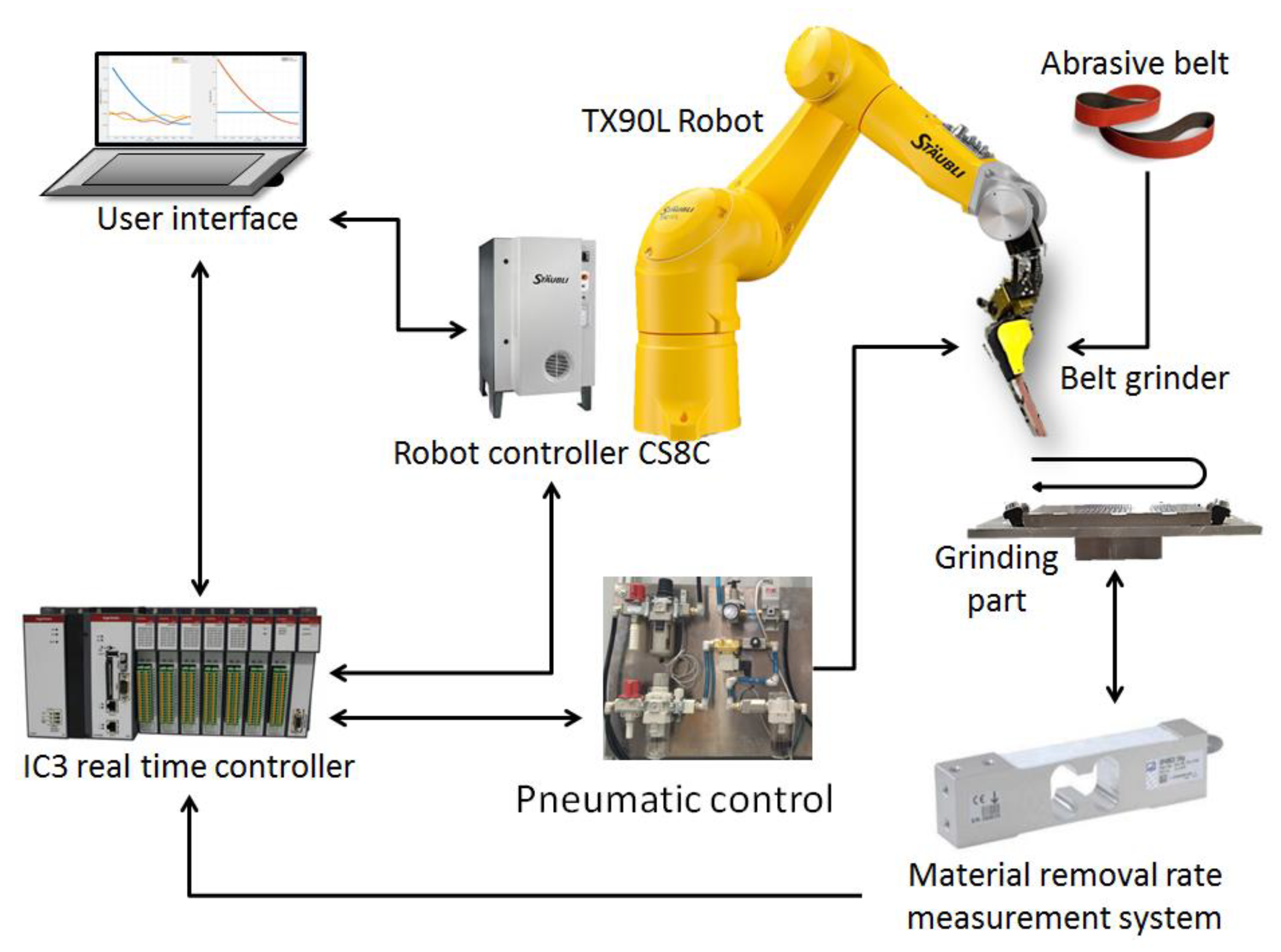
The materials and set-up are illustrated in Figure 1. The pneumatic belt grinding tool is located in the flange of a Stäubli TX90L robot, with a nominal load capacity of 15 kg and a reach at writs of 1200 mm. The robot controller is a CS8C with Ethernet IP and Modbus communication protocols.
The setup includes an automatic material removal measurement system based on a precision load cell system. The test part to be studied is located on the measurement system.
Process data acquisition and the material removal control algorithm for homogeneous finishing are executed in an Ingeteam IC3 real-time controller and developed on Matlab-Simulink. The real-time controller communicates with the robot controller to command the robot feed rate modifications according to the control algorithm. The real-time controller also acquires the content from the measurement system and manages the activation of the pneumatic system of the tool.
Additionally, a user interface monitors data from the process by Modbus communications with the real-time and robot controllers.
2.1.1. Grinding Tool
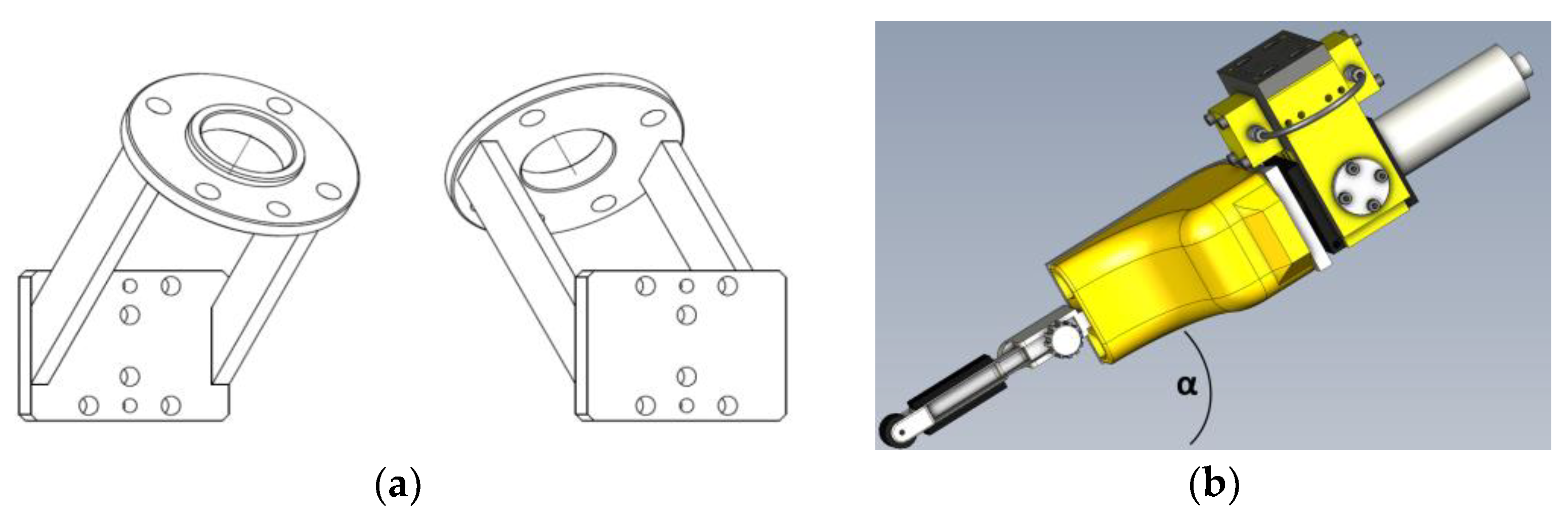
The belt grinding tool is an AMTRU Swingbelt 120 (Figure 2b). This grinding tool model was chosen in order to maximize the flexibility and adaptability of the robotic grinding process, and to ease the reach of the tool on complex surfaces of the part. The diameter of the tip of the tool is 18 mm, and the width of the belt is 12 mm. It is equipped with a radial-compliant system to control the force during finishing. This radial compliance system has a range of rotation of ±3.8 degrees.
The rotational speed of the tool and the compliance force are pneumatically controlled. The rotational speed of the belt is controlled by the airflow. It can be manually adjusted by a regulator on the pneumatic system and the activation and deactivation are controlled with the real-time controller. For this model, the rotational speed is up to 20,000 rpm, which is equivalent to a linear belt velocity of 31 m/s. The compliance force between the belt and the surface of the part is driven by a pressure level controlled by the real-time controller with an analog voltage value. The grinding arm gets a torque of 4.5 N·m.
The tool is attached to the flange of the robot with a custom-designed mechanical adapter, which is angled at 45 degrees with respect to the flange of the robot to improve the accessibility to the part and avoid singularity poses (Figure 2a).
2.1.2. Abrasive Belts
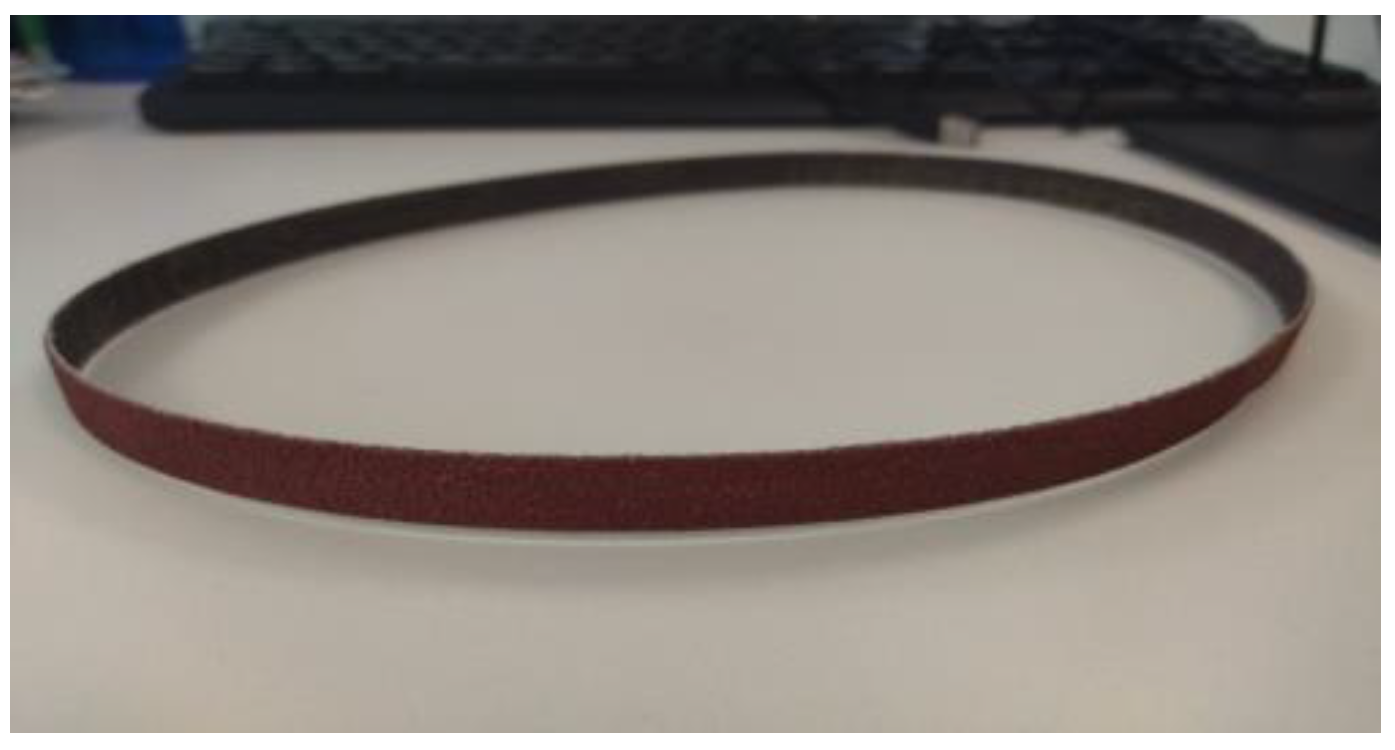
The number of abrasive belts available on the market is huge, and after benchmarking between different models, the 3M Cubitron II 984F Belt was selected. These belts are a novel solution for heavy grinding. The material proposed by 3M is made of a ceramic material over a polyester cloth, and the grits on the belt have a pyramidal shape for an optimized uniformity of the grinding process. Moreover, they are electrostatically oriented to increase the cutting efficiency. The belt offers a good lifetime and a good removal rate.
Two different Cubitron II belts were analyzed: Grit 36 (Figure 3) for heavy roughing operations and grit 80 for roughing or semi-finishing operations. The belts are, according to the selected tool, 610 mm long and 12 mm wide.
2.1.3. Materials
Inconel is a family of nickel–chromium-based super alloys that are widely used in many applications due to their high resistance to corrosion and heat. They are made primarily of nickel, chromium, and iron, with smaller amounts of other elements such as molybdenum, titanium, and aluminum. The combination of these elements makes it ideal for use in high-temperature and corrosive environments. One of the key advantages of Inconel is its ability to retain its strength and ductility even at high temperatures, which allows it to withstand extreme conditions without becoming brittle and breaking. This makes it ideal for use in high-temperature applications such as energy or aeronautics. In particular, Inconel 718 was used in this article due to its use in the aeronautical industry.
2.1.4. Material Removal Measurement System
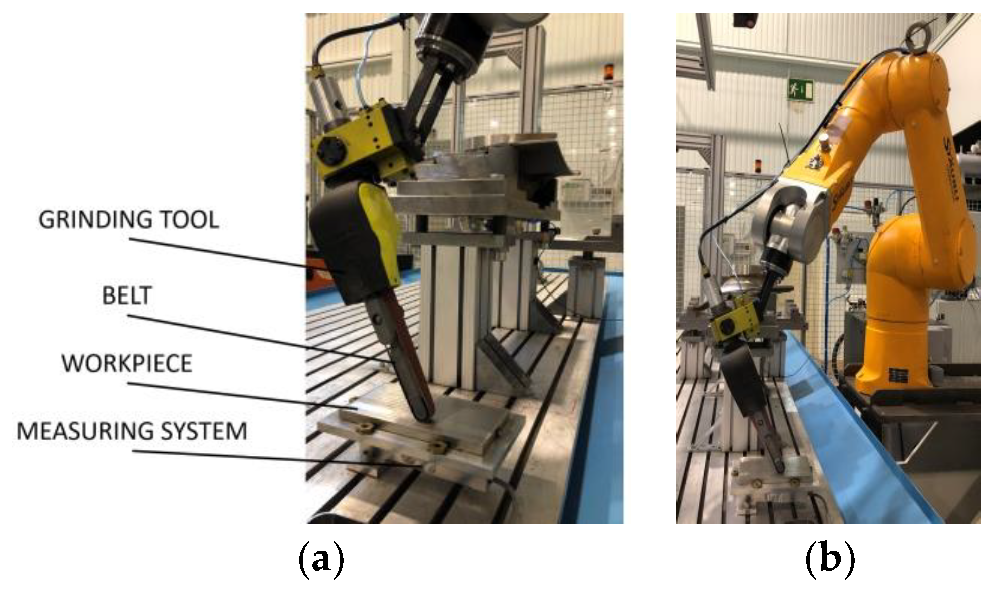
A material removal measurement system is included for the automation of the experimental modeling (Figure 4). The material removal rate of a process can be defined based on the mass loss of the part during the process. The measurement system is a dynamometric table built with a strain gauge and EtherNet/IP connectivity to avoid analogic transmission noise. The system is based on a load cell to measure the mass of the part: HBM SP4M, capacity of 3 kg, and precision of 0.01 g.
A part of Inconel 718 is located on the system. The size of the part is fixed (160 × 90 × 40 mm) to simplify the material removal modeling process. For part location, the measuring system position is referenced to a frame; additionally, the workpiece is clamped with four bolts to the load cell.
2.2. Method
The material removal rate is usually defined by a polynomial curve, and it can be modeled by a negative polynomial of the form:
For belt grinding, a simplified linear model for the material removal rate, which is a function of several process conditions, was described by Hammann in [24]:
where is the removal rate, is a constant of the grinding process, is a constant that represents the ability of the material to be finished by the chosen belt material, is the belt wear factor, is the grinding rate, is the feed rate, is the machining width, and is the thrust force.
Except for the belt wear, which is known to dynamically change during the process, the other variables can be considered constant. Therefore, the material removal model can be simplified as:
According to Equation (3), it can be concluded that the shape of the abrasive belt’s wear is the same as the material removal rate.
Under this consideration and for certain process variables, a material removal model can be experimentally obtained by measuring the mass loss of the finished part. This process is appropriate for materials with a high density and high material removal rates.
where ΔV is the volume difference between measures, Δm is the mass difference, and is the density of the material.
Then, the material removed per pass can be calculated, as the removed volume of the material can be considered as the volume of a prism, where A is the finished area and is the depth of cut or the material removal per pass.
Based on this methodology, an automatic modeling process for material removal is proposed. The robot is commanded to repeatedly execute a certain number of finishing passes on the test part, which is on the measurement system. Once the passes are completed, the robot stops, and the real-time controller acquires the mass measurement of the part. This process is repeated over the life span of the abrasive belt. As the process parameters are known, the material removal can be modeled based on the experimental data.
According to the previously described model, the material removal control algorithm is defined. Experimental data from the model can be used to tune the control algorithm for maintaining a constant material removal over the life of the belt. As material removal is defined for each step, data can be extrapolated to calculate the feed rate for that material removal value.
3. Results
This section aims to validate the proposed control algorithm for homogeneous robotic finishing. The control objective is to maintain a constant material removal rate during the finishing process by adapting the robot’s feed rate while the rest of the process conditions are fixed. As the control algorithm requires information from the process, several tests were performed with the proposed methodology in order to obtain the experimental material removal models for different process conditions.
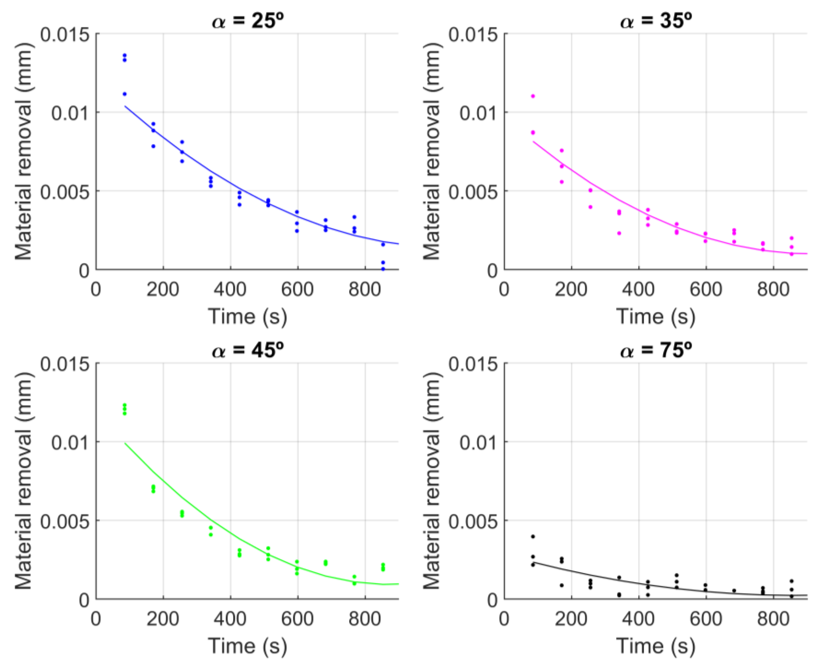
Seven different material removal models were obtained, each with different process conditions. For each model, three tests were executed; then, the data were fitted to a second-order polynomial and stored as the experimental model. The variables that affect the material removal rate are specified in Equation (2). Four variables were kept fixed for all the tests: The material and manufacturing process of the Inconel 718 test part was always the same, the grinding rate was pneumatically activated with a value of approximately 30 m/s (the air flux varies from 310 to 340 L/min), the machining width was a belt width of 12 mm, and the robot’s feed rate was constant at 75 mm/s. The two other variables were modified to obtain different models. Two abrasive belts were used: Grit 36 for heavy roughing and grit 80 for roughing. The thrust force was modified by the cutting angle α, while the compliance force kept constant. Cutting angles of 25, 35, 45, and 75 degrees were chosen to cover the typical working values range.
The results for the experimental material removal per pass for abrasives with a grit of 36, a feed rate of 75 mm/s, and different cutting angles are shown in Figure 5. As expected according to Equation (2), the smaller the cutting angle or the bigger the thrust force, the bigger the volume of material removed per pass. For small angles, a bigger difference occurred at the beginning of the process, while at the end, the three cases are very similar (25, 35, and 45 degrees). For the 75 degree case, the material removal per pass was smaller and constant during the whole process.
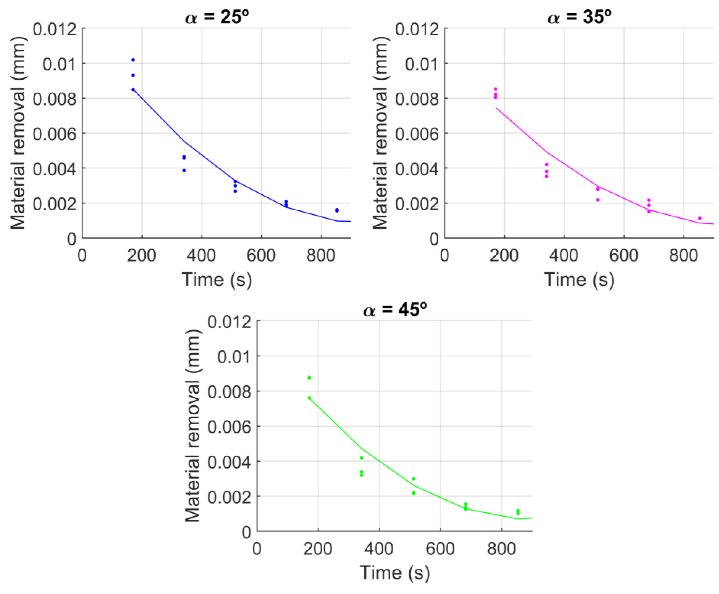
The results for the experimental material removal per pass for abrasives with a grit of 80, a feed rate of 75 mm/s, and different cutting angles are shown in Figure 6. In this case, the same trend as that seen in Figure 5 appeared, where the material removal was bigger for smaller angles, albeit very similar in all the cases. Comparing the material removal per pass of grit 36 with grit 80, the values were very similar because both abrasives offer high material removal rates. Tests with a cutting angle of 75 degrees were not repeated for grit 80 abrasive belts, because it was already seen in Figure 5 that the material removal rate was very low for grit 36 abrasive belts.
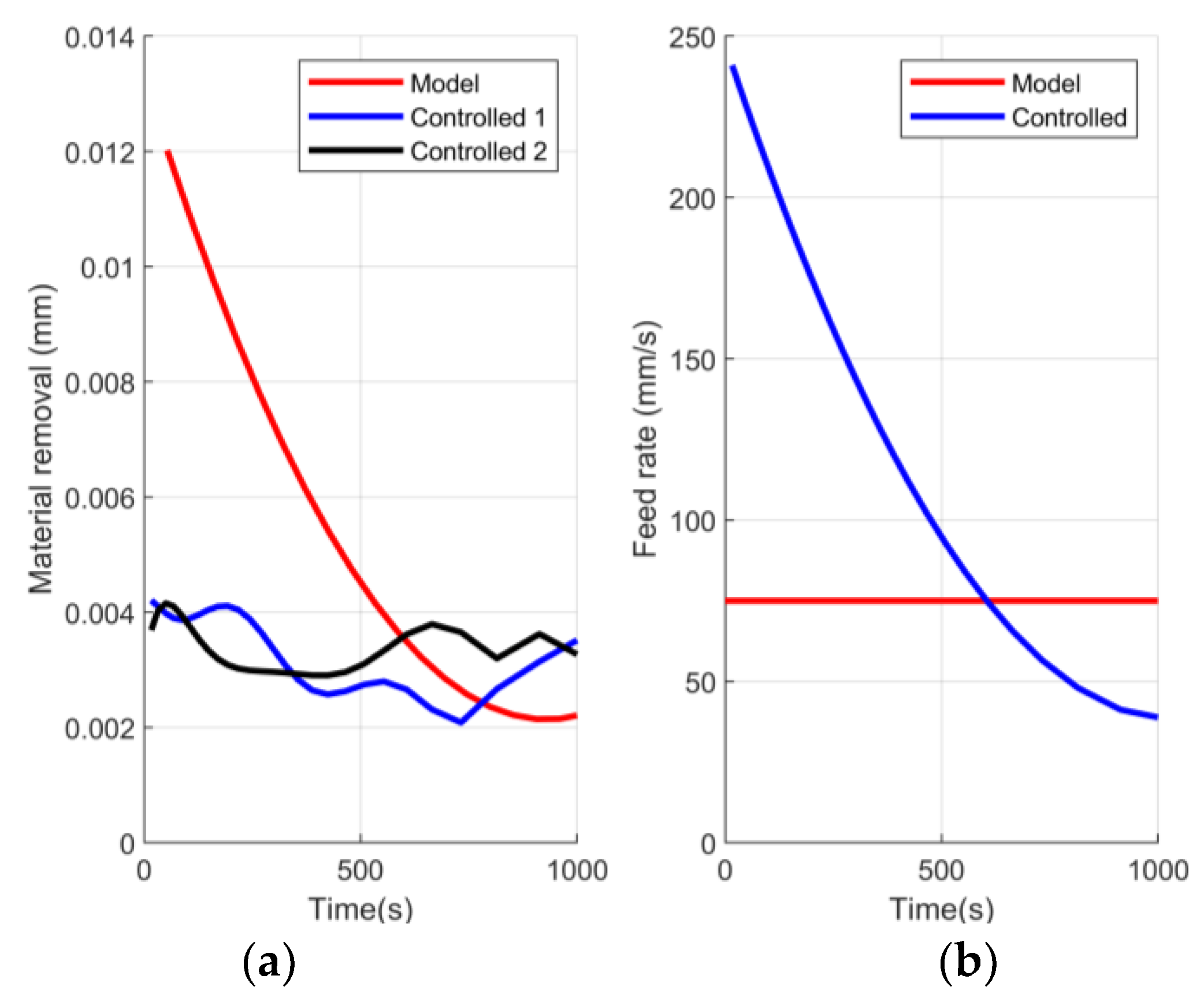
Finally, the proposed material removal control algorithm for homogeneous robotic finishing was validated. From the previously developed experimental models, the process conditions of a cutting angle of 25 degrees and abrasive belts of grit 36 were chosen. The robot’s feed rate was controlled to obtain a constant material removal per pass of 0.004 mm. Figure 7a shows a comparison of the material removed when grinding with and without the robot’s feed control. Meanwhile, with a constant feed rate of the robot, the material removal varied during the process and the controlled process maintained an average material removal of 0.0034 mm per pass. Figure 7b illustrates the robot’s feed variation for the two approaches. Hence, when applying the control, at the beginning of the process, the feed rate was high, but when the material removal rate was also high, it progressively decreased. Considering that a heavy finishing process requires several passes, a finishing process with the proposed control algorithm for continuous material removal will generate a homogeneous surface. Without control over the process, the resultant surface will have an irregular thickness.
4. Future Work
Future work involves the development of a material removal model that takes into account the wear of the belt as a variable factor. As seen in this paper, during the process, the material removal was affected by several parameters, with wear being the most important. A deeper study of the material removal mechanism will allow understanding the physics of the cutting process. With this knowledge, a material removal model of industrial interest will be formulated, while experimental tests will allow calibrating and validating it. A variable wear factor will adapt the removal capacity of the belt depending on the belt process history at each step, unlike the current constant wear factors.
Additionally, future work will include the grinding of complex geometry parts for testing the models in shapes of industrial interest. Moreover, the grinding compliance mechanism needs to be explained and included in grinding simulations.
5. Conclusions
A material removal control algorithm for homogeneous robotic finishing was proposed in this paper. This approach guarantees a constant material removal rate for homogeneous finishing during the process by controlling the robot’s feed rate.
This control algorithm uses experimental data for the material removal model, so a methodology for automatic data acquisition was proposed. The measurement system is based on mass loss measurements. The proposed modeling methodology was used to acquire the material removal rate under eight different process conditions for comparison purposes. The main variations were determined based on the thrust force by varying the cutting angle. The thrust force had a big effect on the material removal, since it achieved a high material removal rate with small cutting angles, while the material removal rate remained small with big angles. Moreover, a similar effect was obtained by modifying the feed rate, as with a higher value, the material removal rate remained small. Additionally, two types of grinding belts were used: Grit 36 for heavy roughing and grit 80 for roughing. Abrasive belts with grit 36 achieved a higher material removal rate of around 15% than abrasive belts with grit 80.
Finally, the proposed approach of material removal control for homogeneous robotic finishing was validated on a test part. The results showed that the control algorithm managed to maintain a constant material removal.
Author Contributions
Conceptualization, S.M. and R.T.; methodology, D.B.; validation, S.M., R.T. and X.I.; writing—original draft preparation, R.T. and S.M.; writing—review and editing, D.B and X.I.; supervision, D.B. All authors have read and agreed to the published version of the manuscript.
Funding
This research was funded by the EUROSTARS GRINDBOT project (grant number E!115077) and the Government of Navarre Doctorados Industriales program (grant number 0011-1408-2021-000021).
Data Availability Statement
Data available on request due to privacy restrictions.
Conflicts of Interest
The authors declare no conflict of interest.
References
- Coykendall, J.; Wellener, P.; Hardin, K. Aerospace and Defense Industry Outlook; Deloitte: London, UK, 2022. [Google Scholar]
- Pires, J.N.; Bogue, R. Finishing robots: A review of technologies and applications. Ind. Robot. Int. J. 2009, 36, 6–12. [Google Scholar]
- Fernandez, A.; Jose Antonio, D.; Javierre, C.; Jorge, S. Surface roughness evolution model for finishing using an abrasive tool on a robot. Int. J. Adv. Robot. Syst. 2015, 12, 119. [Google Scholar] [CrossRef] [Green Version]
- Zhu, D.; Feng, X.; Xu, X.; Yang, Z.; Li, W.; Yan, S.; Ding, H. Robotic grinding of complex components: A step towards efficient and intelligent machining–challenges, solutions, and applications. Robot. Comput. Integr. Manuf. 2020, 65, 101908. [Google Scholar] [CrossRef]
- Khellouki, A.; Rech, J.; Zahouani, H. Energetic analysis of cutting mechanisms in belt finishing of hard materials. J. Eng. Manuf. 2013, 9, 1409–1413. [Google Scholar] [CrossRef]
- Thomessen, T.; Lien, T.K.; Sannæs, P.K. Robot control system for grinding of large hydro power turbines. Ind. Robot. Int. J. 2001, 28, 328–334. [Google Scholar] [CrossRef]
- Xiao, G.; Gao, H.; Zhang, Y.; Zhu, B.; Huang, Y. An intelligent parameters optimization of titanium alloy belt grinding considering machining efficiency and surface quality. Int. J. Adv. Manuf. Technol. 2023, 125, 513–527. [Google Scholar] [CrossRef]
- Song, Y.; Liang, W.; Yang, Y. A method for grinding removal control of a robot belt grinding system. J. Intell. Manuf. 2012, 23, 1903–1913. [Google Scholar] [CrossRef]
- Xie, H.L.; Wang, Q.H.; Ong, S.K.; Li, J.R.; Chi, Z.P. Adaptive human-robot collaboration for robotic grinding of complex workpieces. CIRP Ann. 2022, 71, 285–288. [Google Scholar] [CrossRef]
- Ren, X.; Kuhlenkötter, B.; Müller, H. Simulation and verification of belt grinding with industrial robots. Int. J. Mach. Tools Manuf. 2006, 46, 708–716. [Google Scholar] [CrossRef]
- Yang, H.Y.; Shih, C.H.; Lo, Y.C.; Lian, F.L. Zero-tuning grinding process methodology of cyber-physical robot system. In Proceedings of the IEEE/RSJ International Conference on Intelligent Robots and Systems, Las Vegas, NV, USA, 24 October 2020–24 January 2021; pp. 4270–4275. [Google Scholar]
- Zhang, G.; Liu, C.; Min, K.; Liu, H.; Ni, F. A GAN-BPNN-based surface roughness measurement method for robotic grinding. Machines 2022, 10, 1026. [Google Scholar] [CrossRef]
- Pandiyan, V.; Caesarendra, W.; Tjahjowidodo, T.; Praveen, G. Predictive modelling and analysis of process parameters on material removal characteristics in abrasive belt grinding process. Appl. Sci. 2017, 7, 363. [Google Scholar] [CrossRef]
- Pandiyan, V.; Caesarendra, W.; Glowacz, A.; Tjahjowidodo, T. Modelling of material removal in abrasive belt grinding process: A regression approach. Symmetry 2020, 12, 99. [Google Scholar] [CrossRef] [Green Version]
- ABB. Available online: https://new.abb.com/products/robotics/application-equipment-and-accessories/integrated-force-control (accessed on 27 March 2023).
- Xie, X.; Sun, L. Force control based robotic grinding system and application. In Proceedings of the 12th World Congress on Intelligent Control and Automation (WCICA), Guilin, China, 12–15 June 2016; pp. 2552–2555. [Google Scholar]
- Wang, Q.; Wang, W.; Zheng, L.; Yun, C. Force control-based vibration suppression in robotic grinding of large thin-wall shells. Robot. Comput. Integr. Manuf. 2021, 67, 102031. [Google Scholar] [CrossRef]
- Wang, T.; Miao, H.; Shi, S.; Chen, Z.; Zhang, H. A method of robot grinding force control based on internal model control principle. J. Phys. Conf. Ser. 2021, 1748, 022026. [Google Scholar] [CrossRef]
- Zhang, J.; Liu, G.; Zang, X.; Li, L. A hybrid passive/active force control scheme for robotic belt grinding system. In Proceedings of the IEEE International Conference on Mechatronics and Automation, Harbin, China, 5 September 2016; pp. 737–742. [Google Scholar]
- Yan, S.; Xu, X.; Yang, Z.; Zhu, D.; Ding, H. An improved robotic abrasive belt grinding force model considering the effects of cut-in and cut-of. J. Manuf. Process. 2019, 37, 496–508. [Google Scholar] [CrossRef]
- Chen, F.; Zhao, H.; Li, D.; Chen, L.; Tan, C.; Ding, H. Robotic grinding of a blisk with two degrees of freedom contact force control. Int. J. Adv. Manuf. Technol. 2019, 101, 461–474. [Google Scholar] [CrossRef]
- Robertsson, A.; Olsson, T.; Johansson, R.; Blomdell, A.; Nilsson, K.; Haage, M.; Brantmark, H. Implementation of industrial robot force control case study: High power stub grinding and deburring. In Proceedings of the IEEE/RSJ International Conference on Intelligent Robots and Systems, Beijing, China, 9–15 October 2006; pp. 2743–2748. [Google Scholar]
- Domroes, F.; Krewet, C.; Kuhlenkoetter, B. Application and analysis of force control strategies to deburring and grinding. Mod. Mech. Eng. 2013, 3, 33474. [Google Scholar] [CrossRef] [Green Version]
- Hammann, G. Modeling the Removal Behavior of Elastic, Robot-Guided Grinding Tools; Springer: Berlin/Heidelberg, Germany, 2013; Volume 123. [Google Scholar]
Figure 1.
Setup of the materials used for the material removal rate data acquisition and the control algorithm.
Figure 1.
Setup of the materials used for the material removal rate data acquisition and the control algorithm.

Figure 2.
Design of the adapter with an angle of 45 degrees: (a) Design of the custom mechanical adapter; (b) CAD model of the tool showing the cutting angle α.
Figure 2.
Design of the adapter with an angle of 45 degrees: (a) Design of the custom mechanical adapter; (b) CAD model of the tool showing the cutting angle α.

Figure 3.
3M Cubitron II 984F belt of grit 36.

Figure 4.
Material removal rate measurement system based on: (a) HBM SP4M load cell; (b) robotic finishing on the test part.
Figure 4.
Material removal rate measurement system based on: (a) HBM SP4M load cell; (b) robotic finishing on the test part.

Figure 5.
Material removal models for different cutting angles with a grit 36 abrasive and a 75 mm/s feed rate.
Figure 5.
Material removal models for different cutting angles with a grit 36 abrasive and a 75 mm/s feed rate.

Figure 6.
Material removal models for different cutting angles with a grit 80 abrasive and a 75 mm/s feed rate.
Figure 6.
Material removal models for different cutting angles with a grit 80 abrasive and a 75 mm/s feed rate.

Figure 7.
Controlled robot’s feed rate for a constant material removal of 0.004 mm per pass: (a) Material removal of one model and two controlled processes; (b) the robot’s feed rate variation.
Figure 7.
Controlled robot’s feed rate for a constant material removal of 0.004 mm per pass: (a) Material removal of one model and two controlled processes; (b) the robot’s feed rate variation.

Disclaimer/Publisher’s Note: The statements, opinions and data contained in all publications are solely those of the individual author(s) and contributor(s) and not of MDPI and/or the editor(s). MDPI and/or the editor(s) disclaim responsibility for any injury to people or property resulting from any ideas, methods, instructions or products referred to in the content. |
© 2023 by the authors. Licensee MDPI, Basel, Switzerland. This article is an open access article distributed under the terms and conditions of the Creative Commons Attribution (CC BY) license (https://creativecommons.org/licenses/by/4.0/).
Share and Cite
MDPI and ACS Style
Torres, R.; Mata, S.; Iriarte, X.; Barrenetxea, D. Robotic Belt Finishing with Process Control for Accurate Surfaces. J. Manuf. Mater. Process. 2023, 7, 124. https://doi.org/10.3390/jmmp7040124
AMA Style
Torres R, Mata S, Iriarte X, Barrenetxea D. Robotic Belt Finishing with Process Control for Accurate Surfaces. Journal of Manufacturing and Materials Processing. 2023; 7(4):124. https://doi.org/10.3390/jmmp7040124
Chicago/Turabian StyleTorres, Ramón, Sara Mata, Xabier Iriarte, and David Barrenetxea. 2023. "Robotic Belt Finishing with Process Control for Accurate Surfaces" Journal of Manufacturing and Materials Processing 7, no. 4: 124. https://doi.org/10.3390/jmmp7040124