Analysis of the Process Parameter Influence in Laser Cladding of 316L Stainless Steel


Abstract
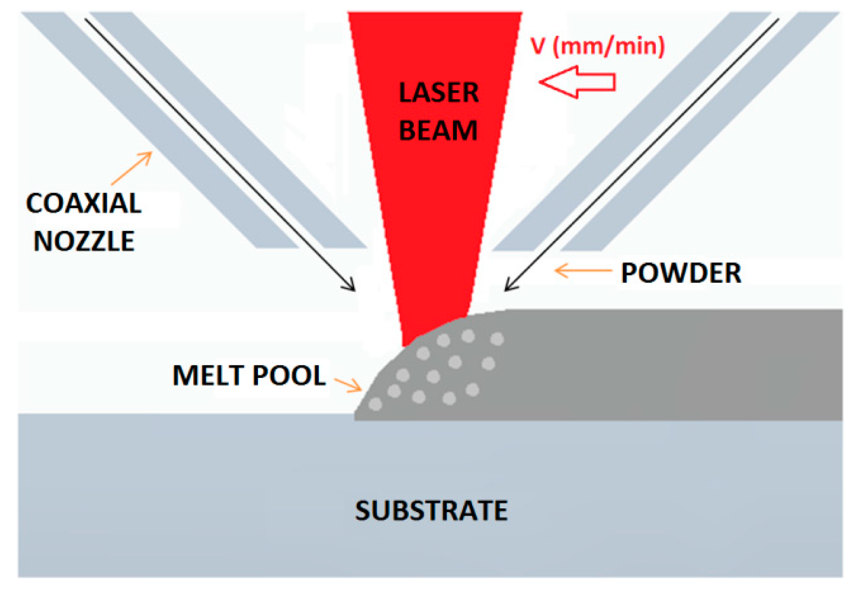
:1. Introduction
2. Materials and Methods
2.1. Material Preparation
2.2. Used Equipment
2.3. Experimental Procedure
3. Results and Discussion
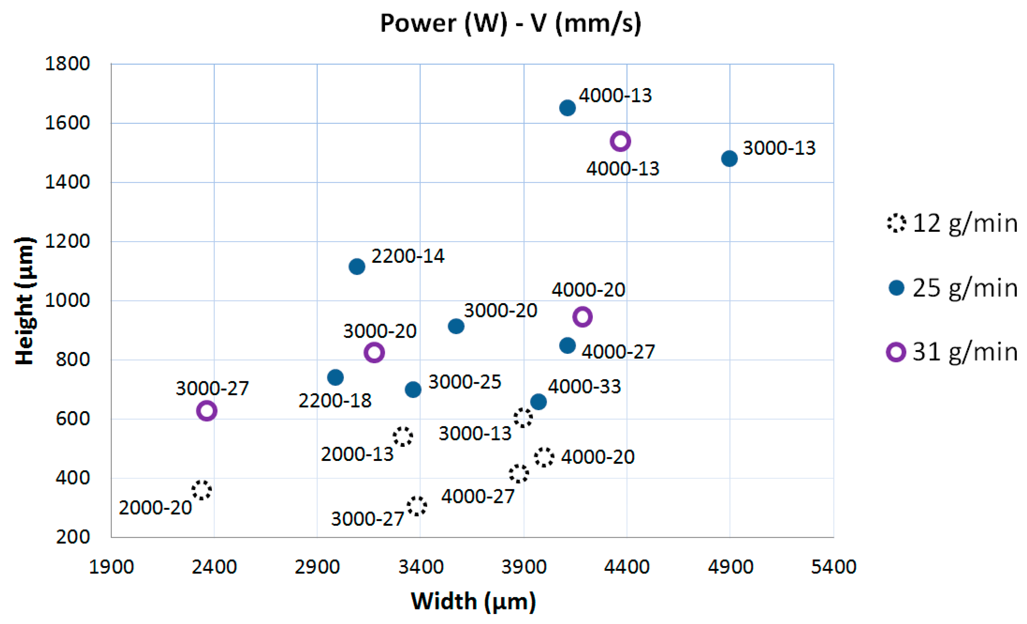
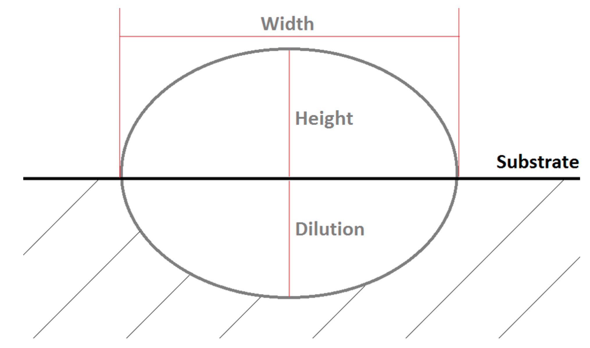
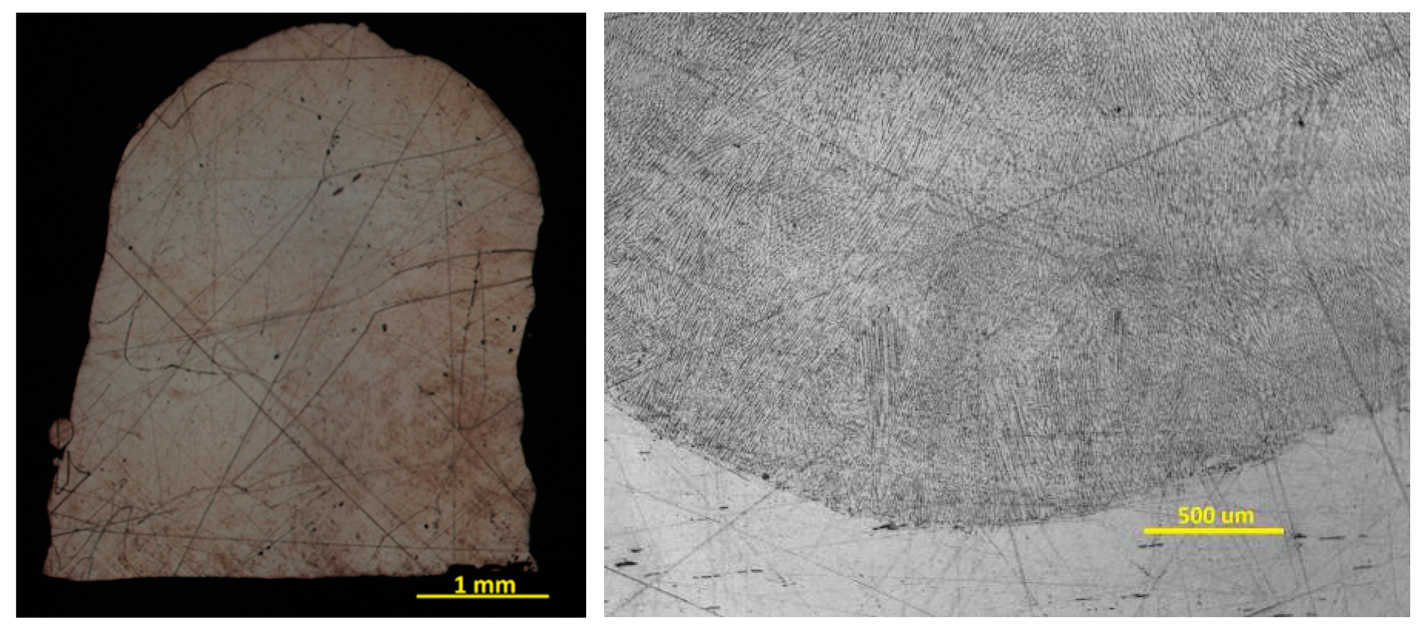
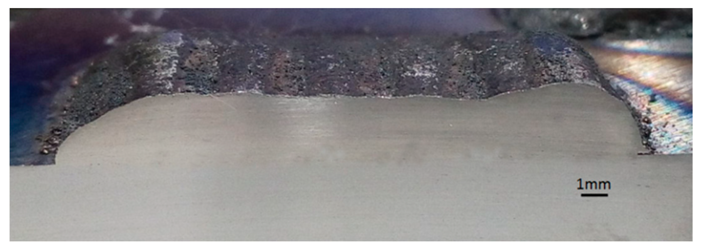
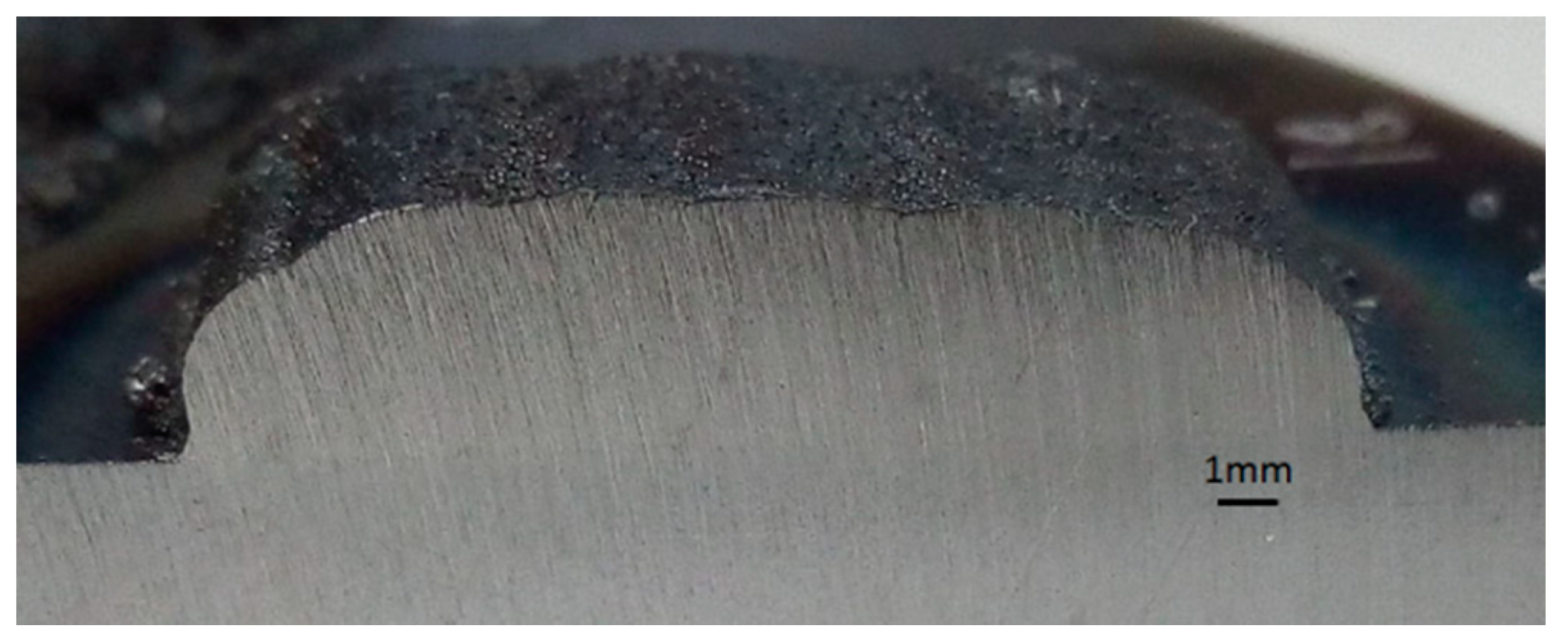
3.1. Individual Clad Experiments
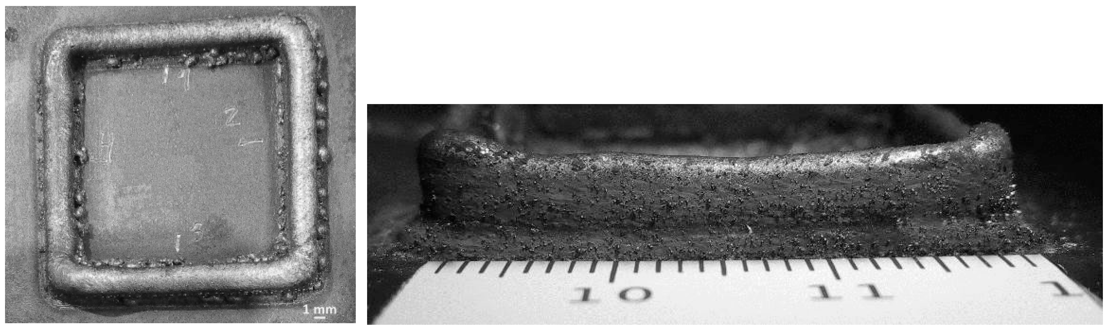
3.2. Multiple Clad Experiments (Solid Forms)
3.3. Parameter Reduction and Building of a Solid Form
- Power range: 2000–3000 W
- Process speed: 13 mm/s
- Powder flow: 25 g/min
- Overlap percentage: 30%
- Increase in average height per layer: 0.8 mm
4. Conclusions
- A good metallurgical bond was achieved when depositing AISI 316L stainless steel via LC, thanks to the good relation between 25 g/min of powder flow and 30% of overlap, which guaranteed a dilution value of less than 20% in lower process time and, in the case of solid forms, without lack of fusions. In addition, it is necessary to modulate the laser power during the coating process (from 3000 W to 2000 W), in order to maintain control of the process, avoiding overheating of the piece.
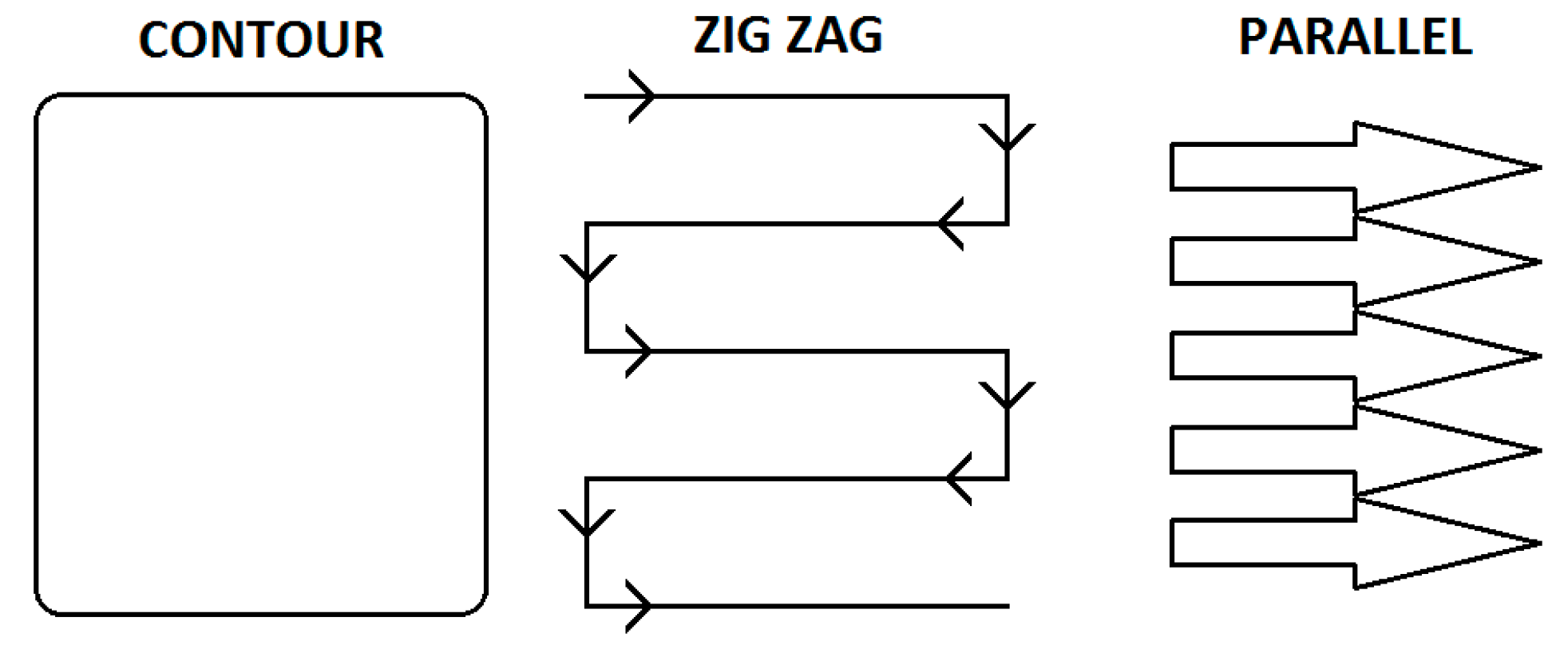
- Regarding the strategies studies, it can be seen that the Zig Zag strategy is the best to ensure the maximum increase of the height of the deposited layer, and the Parallel strategy can be used to achieve a more homogeneous layer height.
Author Contributions
Funding
Acknowledgments
Conflicts of Interest
References
- Ziętala, M.; Durejko, T.; Polański, M.; Kunce, I.; Płociński, T.; Zieliński, W.; Łazińska, M.; Stępniowski, W.; Czujko, T.; Kurzydłowski, K.J.; et al. The microstructure, mechanical properties and corrosion resistance of 316 L stainless steel fabricated using laser engineered net shaping. Mater. Sci. Eng. A 2016, 677, 1–10. [Google Scholar] [CrossRef]
- Pei, Y.T.; De Hosson, J.T.M. Functionally graded materials produced by Laser cladding. Acta Mater. 2000, 48, 2617–2624. [Google Scholar] [CrossRef]
- Pinkerton, A.J. Lasers in additive manufacturing. Opt. Laser Technol. 2016, 78, 25–32. [Google Scholar] [CrossRef] [Green Version]
- Castro, G.; Rodriguez, J.; Montealegre, M.A.; Arias, J.L.; Yañez, A.; Panedas, S.; Rey, L. Laser additive manufacturing of high added value pieces. Procedia Eng. 2015, 132, 102–109. [Google Scholar] [CrossRef]
- MANUFUTURE Platform. Strategic Research Agenda: Assuring the Future of a Competitive and Sustainable Manufacturing in Europe. 2006. Available online: http://www.manufuture.org/strategic-research-agenda/ (accessed on 14 August 2018).
- Cortina, M.; Arrizubieta, J.I.; Calleja, A.; Ukar, E.; Alberdi, A. Case Study to Illustrate the Potential of Conformal Cooling Channels for Hot Stamping Dies Manufactured Using Hybrid Process of Laser Metal Deposition (LMD) and Milling. Preprints 2017, 2017120076. [Google Scholar] [CrossRef]
- Langefeld, B. Additive Manufacturing. A Game Changer for the Manufacturing Industry? Roland Berger Strategy Consultants: Munich, Germany, 2013. [Google Scholar]
- Montealegre, M.A.; Vidal, F.; Mann, S.; Abels, P.; Motmans, F.; Walter, A.; Kogel-Hollacher, M.; Palatka, P.; Franch, R.; Lovec, F. Adaptive laser cladding system with variable spot sizes. In Proceedings of the 2013 International Congress on Applications of Lasers and Electro-Optics, Congress Proceedings (ICALEO), Miami, FL, USA, 6–10 October 2013; pp. 950–954, ISBN 978-0-912035-98-7. [Google Scholar]
- Klocke, F.; Brecher, C.; Heinen, D.; Rosen, C.; Breitbach, T. Flexible scanner-based laser surface treatment. Phys. Procedia 2010, 5, 467–475. [Google Scholar] [CrossRef]
- Pekkarinen, J. Laser Cladding with Scanning Optics. Ph.D. Thesis, University of Technology, Lappeenranta, Finland, 2014. [Google Scholar]
- Li, Y.; Yang, H.; Lin, X.; Huang, W.; Li, J.; Zhou, Y. The influences of processing parameters on forming characterizations during laser rapid forming. Mater. Sci. Eng. A 2003, 360, 18–25. [Google Scholar] [CrossRef]
- Calleja, A.; Tabernero, I.; Fernández, A.; Celaya, A.; Lamikiz, A. Improvement of strategies and parameters for multi-axis laser cladding operations. Opt. Lasers Eng. 2014, 56, 113–120. [Google Scholar] [CrossRef]
- Goodarzi, D.M.; Pekkarinen, J.; Salminen, A. Effect of process parameters in laser cladding on substrate melted areas and the substrate melted shape. J. Laser Appl. 2015, 27, S29201. [Google Scholar] [CrossRef]
- Ding, D. Process Planning for Robotic Wire ARC Additive Manufacturing. Ph.D. Thesis, University of Wollongong, Wollongong, Australia, 2015. [Google Scholar]
- Wang, Z.; Palmer, T.A.; Beese, A.M. Effect of processing parameters on microstructure and tensile properties of austenitic stainless steel 304 L made by directed energy deposition additive manufacturing. Acta Mater. 2016, 110, 226–235. [Google Scholar] [CrossRef]
- De Oliveira, U.; Ocelik, V.; De Hosson, J.T.M. Analysis of coaxial laser cladding processing conditions. Surf. Coat. Technol. 2005, 197, 127–136. [Google Scholar] [CrossRef]
- Routhu, S. 2-D path Planning for Direct Laser Deposition Process. Master’s Thesis, Missouri University of Science and Technology, Rolla, MO, USA, 2010. [Google Scholar]
- Huang, Y. Characterization of dilution action in laser-induction hybrid cladding. Opt. Laser Technol. 2011, 43, 965–973. [Google Scholar] [CrossRef]
- Song, B.; Hussain, T.; Voisey, K.T. Laser cladding of Ni50Cr: A parametric and dilution study. Phys. Procedia 2016, 83, 706–715. [Google Scholar] [CrossRef]
- Wolf, M. Improving the Efficiency of the DMLD Process, How Particle Size and Laser Spot Size Influence process Quality and Efficiency. Laser Tech. J. 2016, 13, 32–34. [Google Scholar] [CrossRef]
- Ocylok, S.; Alexeev, E.; Mann, S.; Weisheit, A.; Wissenbach, K.; Kelbassa, I. Correlations of melt pool geometry and process parameters during laser metal deposition by coaxial process monitoring. Phys. Procedia 2014, 56, 228–238. [Google Scholar] [CrossRef]
- Kaynak, Y.; Kitay, O. Porosity, surface quality, microhardness and microstructure of selective laser melted 316 L stainless steel resulting from finish machning. J. Manuf. Mater. Process. 2018, 2, 36. [Google Scholar]
- Nenadl, O.; Ocelík, V.; Palavra, A.; De Hosson, J.T.M. The prediction of coating geometry from main processing parameters in laser cladding. Phys. Procedia 2014, 56, 220–227. [Google Scholar] [CrossRef]


| C | Cr | Ni | Mn | P | Mo | Si | O | Fe | |
|---|---|---|---|---|---|---|---|---|---|
| wt % | ≤0.03 | 17.5 | 11.5 | ≤2 | 0.02 | 2.3 | 0.4 | 0.05 | balance |
| Laser Focus Distance (mm) | Carrier Gas (L/min) | Shielding Gas (L/min) |
|---|---|---|
| 550 | 3 | 5 |
| 2000 W-13 mm/s | 2000 W-20 mm/s |
 |  |
| 3000 W-13 mm/s | 3000 W-27 mm/s |
 |  |
| 4000 W-20 mm/s | 4000 W-27 mm/s |
 |  |
| 2200 W-14 mm/s | 2200 W-18 mm/s |
 |  |
| 3000 W-13 mm/s | 3000 W-20 mm/s |
 |  |
| 3000 W-25 mm/s | |
 | |
| 4000 W-13 mm/s | 4000 W-27 mm/s |
 |  |
| 4000 W-33 mm/s | |
 | |
| 3000 W-20 mm/s | 3000 W-27 mm/s |
 |  |
| 4000 W-13 mm/s | 4000 W-20 mm/s |
 |  |
© 2018 by the authors. Licensee MDPI, Basel, Switzerland. This article is an open access article distributed under the terms and conditions of the Creative Commons Attribution (CC BY) license (http://creativecommons.org/licenses/by/4.0/).
Share and Cite
Alvarez, P.; Montealegre, M.Á.; Pulido-Jiménez, J.F.; Arrizubieta, J.I. Analysis of the Process Parameter Influence in Laser Cladding of 316L Stainless Steel. J. Manuf. Mater. Process. 2018, 2, 55. https://doi.org/10.3390/jmmp2030055
Alvarez P, Montealegre MÁ, Pulido-Jiménez JF, Arrizubieta JI. Analysis of the Process Parameter Influence in Laser Cladding of 316L Stainless Steel. Journal of Manufacturing and Materials Processing. 2018; 2(3):55. https://doi.org/10.3390/jmmp2030055
Chicago/Turabian StyleAlvarez, Piera, M. Ángeles Montealegre, Jose F. Pulido-Jiménez, and Jon Iñaki Arrizubieta. 2018. "Analysis of the Process Parameter Influence in Laser Cladding of 316L Stainless Steel" Journal of Manufacturing and Materials Processing 2, no. 3: 55. https://doi.org/10.3390/jmmp2030055