
Experimental and Finite Element Study of a Novel Two-Way Corrugated Steel Deck System for Composite Slabs


1
School of Engineering, Deakin University, Geelong, VIC 3216, Australia
2
Institute for Frontier Materials, Deakin University, Geelong, VIC 3216, Australia
*
Author to whom correspondence should be addressed.
J. Compos. Sci. 2022, 6(9), 261; https://doi.org/10.3390/jcs6090261
Submission received: 8 August 2022
/
Revised: 27 August 2022
/
Accepted: 5 September 2022
/
Published: 8 September 2022
(This article belongs to the Special Issue Characterization and Modelling of Composites, Volume III)
Abstract
:This paper investigates the structural performance of a new two-way profiled steel decking system for steel-concrete composite slabs. Several studies have investigated steel decking for steel-concrete composite slabs and focused on utilising the conventional deck as a one-way floor system. The newly developed deck consists of top-hat sections formed by bending corrugated sheets at 90°, which are attached to a corrugated base sheet. The deck is designed for improved composite and two-way action contributed by its unique geometry due to corrugations in the transverse and longitudinal directions. This paper experimentally tested a novel steel decking geometry under construction stage loading. It was in the absence of concrete to establish the deck’s suitability for construction and contribution towards loading capacity and performance for future use as a two-way composite slab. Ultimate load, two-way action, and failure modes were identified. A finite element model was also developed, and parameters assessed that could influence the performance when the deck is potentially used in the composite stage. It was concluded that, while increasing the thickness of the corrugated base sheet significantly affects the load-carrying capacity, the thickness of the top hats has no significant impact. Improved load transfer with two-way behaviour is observed when the bottom flanges of the top hats are continuously connected to the bottom flanges of the adjacent top hats to form a deck. This contrasts with the concept deck, where individual top hats are attached to a corrugated base sheet. In this case, decks with a corrugated base sheet perform 54% better in ultimate load capacity than decks without a corrugated base sheet.
1. Introduction
Steel-concrete composite slabs consist of a steel deck with concrete over it. The steel deck acts as a formwork when wet concrete is poured during construction. Once the concrete is hardened, the deck works compositely with the concrete to resist tensile loads acting on the floor. The composite flooring system has been widely adopted due to its ease of construction, low self-weight, and economic savings [1].
The longitudinal shear in composite slabs is primarily transferred between the steel deck and the concrete surface by friction or mechanical interlock. Over the years, different types of steel decks, particularly trapezoidal and re-entrant shaped decks, sometimes with additional features such as embossments, stiffeners or shear studs, have been explored to overcome the failure of composite slabs by slip and separation between the two materials [2,3,4,5,6]. However, in steel-concrete flooring systems, it has been noticed that vertical and longitudinal shear failure [7,8,9] continues to be a controlling issue despite the provision of embossments and shear studs. Moreover, various embossment features such as depth, retention angle, direction and shape are also significantly involved in controlling the shear behaviour in slabs [10]. Therefore, developing a deck that can effectively transfer shear forces is deemed necessary without the need for complex embossment designs. Studies have also shown that local buckling failure has not been completely eliminated in the available steel decks due to inefficient rib geometry, large width-to-thickness ratios of profiled decks, and insufficient tensile and yield strengths of the steel [11].
Further, most of these manufactured decks transfer loads in one-way since they only have formed ribs in one direction [12]. The most commonly available steel-deck types, such as the trapezoidal and re-entrant shapes, were investigated to establish two-way action in different flooring systems such as steel-concrete composite slabs [13,14] and profiled steel sheeting dry board systems [15]. Using both directions of the composite deck slab could increase its load-carrying capacity while at the same time spanning larger column-free areas. Therefore, it is necessary to redesign the deck geometry to incorporate a two-way distribution of loads in composite slabs while maintaining a good shear connection between the steel and concrete materials.
A new two-way steel deck geometry was developed and experimentally investigated for performance parameters such as load-displacement behaviour, failure modes and two-way load transfer. The proposed concept involves introducing 90° bends in the transverse direction of corrugated sheets to form efficient corrugated top-hat ribs, which is the innovative technology developed by FormFlow, Australia [16]. The deck is tested in the construction stage, i.e., without concrete, to assess the behaviour, suitability for construction and contribution of the deck in composite slabs. Testing decks in the construction stage has proven essential for identifying local buckling in decks and establishing maximum slab spans that can be attained for any particular deck type [17,18,19,20,21].
Using ABAQUS [22], a finite element (FE) model of the new two-way deck geometry was developed and verified with experimental results. The validated model was then used to understand the factors influencing the deck’s load capacity and two-way behaviour in the construction stage for improved usage and performance in the composite phase.
2. The Two-Way Corrugated Steel Deck
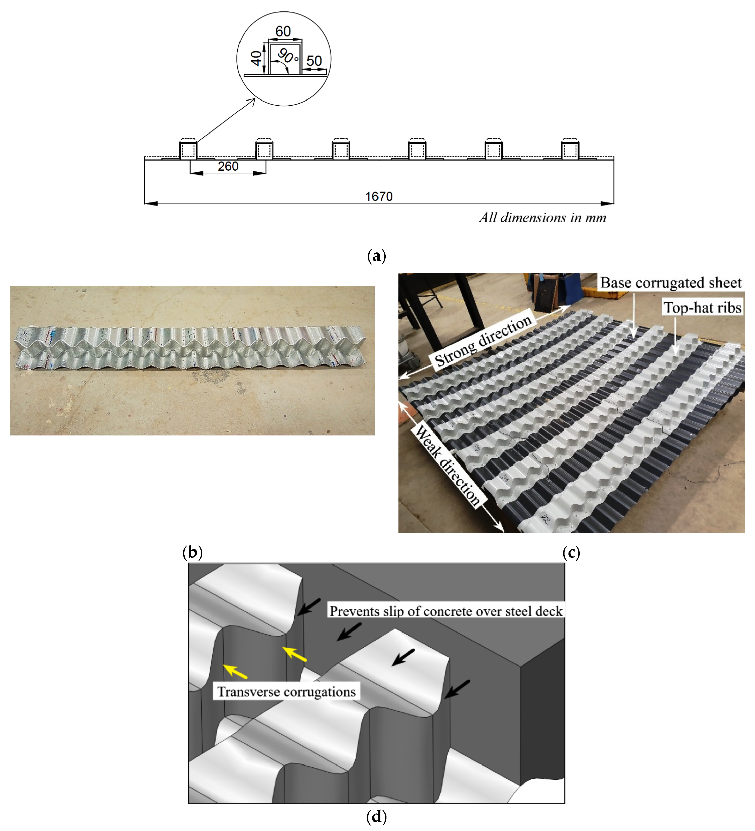
Two corrugated steel decks (D1 and D2) were tested for two-way loading action. The cross-section details are provided in Figure 1a. The samples consist of a corrugated base sheet of 1670 × 1670 mm. Due to longitudinal corrugations, the sheet offers strength along the axis of corrugations. Top hats are formed from these sheets by FormFlow, Australia [16] by introducing bends at 90° to form flanges and webs of the hat, as seen in Figure 1b. These individual top hat sections are placed along the corrugated base sheet at 260 mm centre to centre distance and connected to the corrugated base sheet at the bottom flanges by blind rivets of 3.2 mm diameter. Two top hats were overlaid at the midspan to form a single rib and connected with 3.2 mm rivets at 15 mm rivet spacing. In Figure 1c, the top-hats act as ribs that transfer load in the primary direction, which can be considered the strong direction. The corrugated base sheet acts to transfer load in the secondary direction, considered a weak direction. The dimensions of the top-hat sections and spacing were optimised to provide maximum two-way action. The advantage of the top-hat sections formed from the corrugated sheet is that it offers additional strength due to bends in the corrugations [18]. The unique geometry can also prevent slip due to the varying width of the corrugations across the rib, offering a large shear capacity when concrete is cast over the steel deck in composite slabs. The cross-sectional area of the corrugated geometry hinders the shear failure between the two materials by creating a mechanical interlock, as illustrated in Figure 1. Hence, it is crucial to investigate the deck profile [23] to understand how its behaviour would affect or contribute to the composite stage.
Colorbond steel is a readily and commercially available roofing and decking material. The bend corrugations made from the Colorbond steel are commercially available as Lysaght CUSTOMFLOW [24]. Corrugated steel is vital in a load-carrying capacity along the axis of corrugations. Adding bends to the sheet develops structural shapes with high stiffness that can be used for many applications. The advantage of the bent corrugated sections is that multiple closely spaced bends can be created without any loss of material or space. Further, due to the transverse corrugations on the top hats, the proposed geometry can minimise slip between the two materials, i.e., between the steel deck and the concrete. This steel is 0.42 mm thick with a galvanised zinc of 0.04 mm on one side and a food-grade polymer on the other.
3. Test Setup
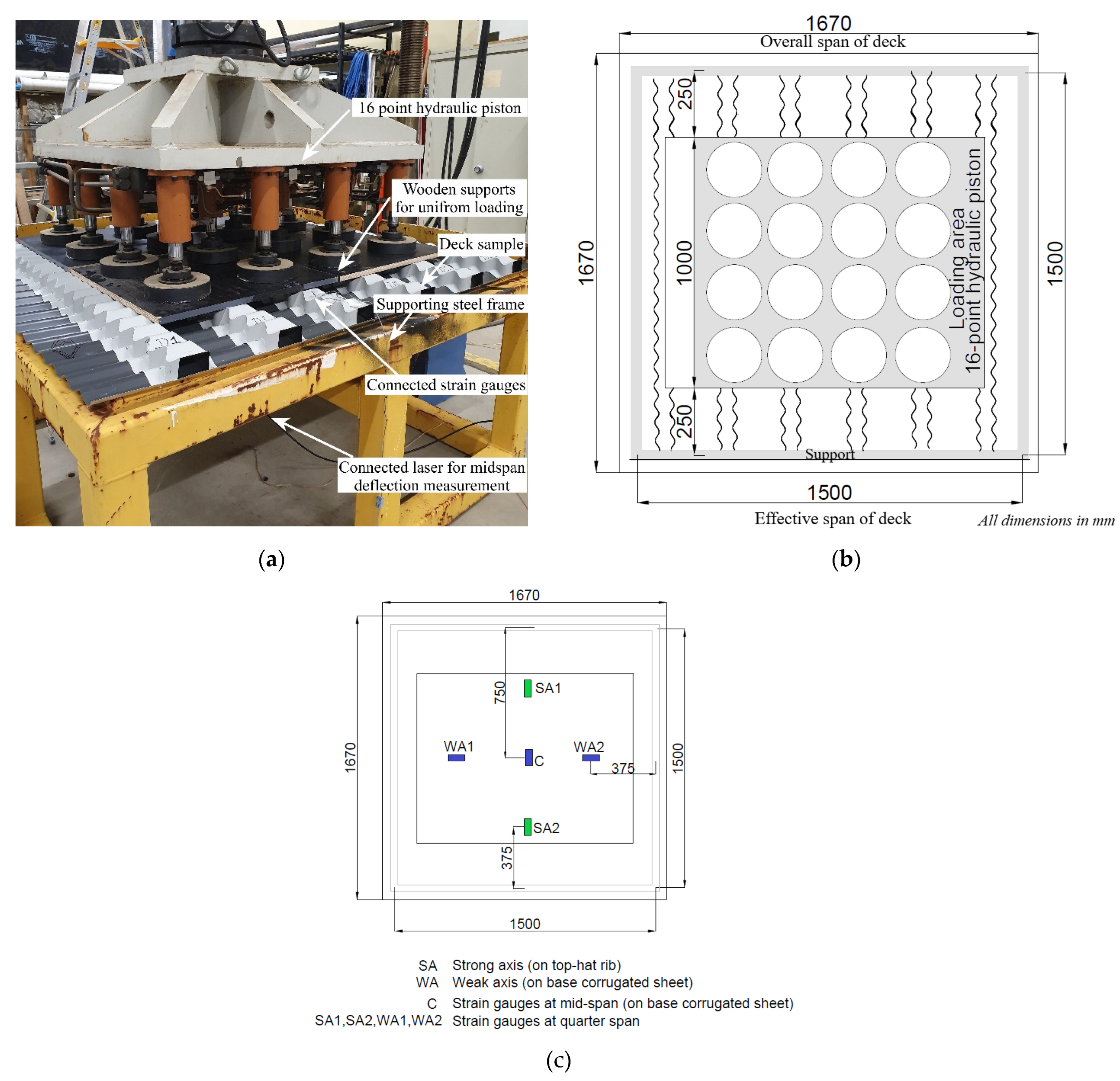
The deck has an overall span of 1670 × 1670 mm and is simply supported at an effective span of 1500 mm × 1500 mm on all four sides, as shown in Figure 2a. The test setup schematic is shown in Figure 2b. A uniform load is applied through a 16-point hydraulic piston attached to a load cell. Wooden supports covering the loading area of 1000 × 1000 mm provides a uniform distribution of the load over all the ribs of the deck. Strain gauges are placed at five points; one on the mid-point, two along the strong direction and two along the weak direction at the quarter span, as seen in Figure 2c. Here the gauges along the strong axis (SA) are placed on the top hats forming the ribs of the deck, whereas the gauges along the weak axis (WA) are placed on the corrugated base sheet at the bottom surface of the deck. A laser transducer is used to measure the vertical deflection at the midspan of the corrugated base sheet. The loading is displacement controlled at 1.5 mm/min, and the load, deflection and strain values are logged through a data acquisition system.
4. Results and Discussion
4.1. Failure Mode
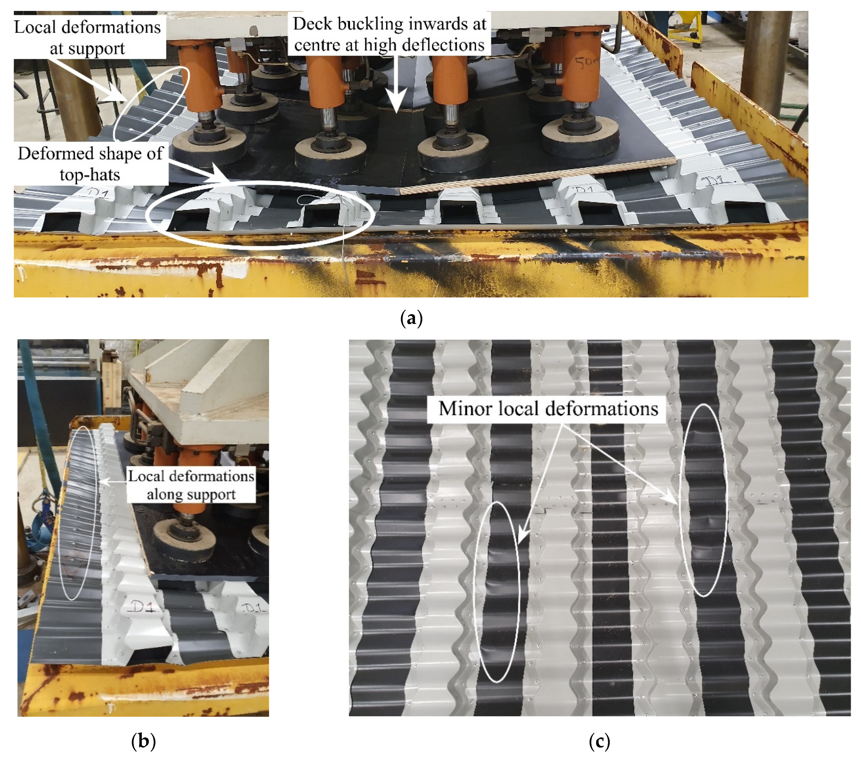
With an increase in load, the top hats that form the ribs tend to collapse towards the centre (Figure 3a) while there is no significant buckling on the deck. Local deformations are noted on the corrugated base sheet of the deck along the supports in the strong direction, as shown in Figure 3b. The deck is supported only on the corrugated base sheet’s peak points, which causes deformation at these points. Further, minor deformation is noticed on the corrugated base sheet in the midspan region of the deck when the ultimate load is reached, Figure 3c. It can be attributed to the deck’s deflection, causing the base sheet to stretch under a high load.
4.2. Load-Displacement Relationship
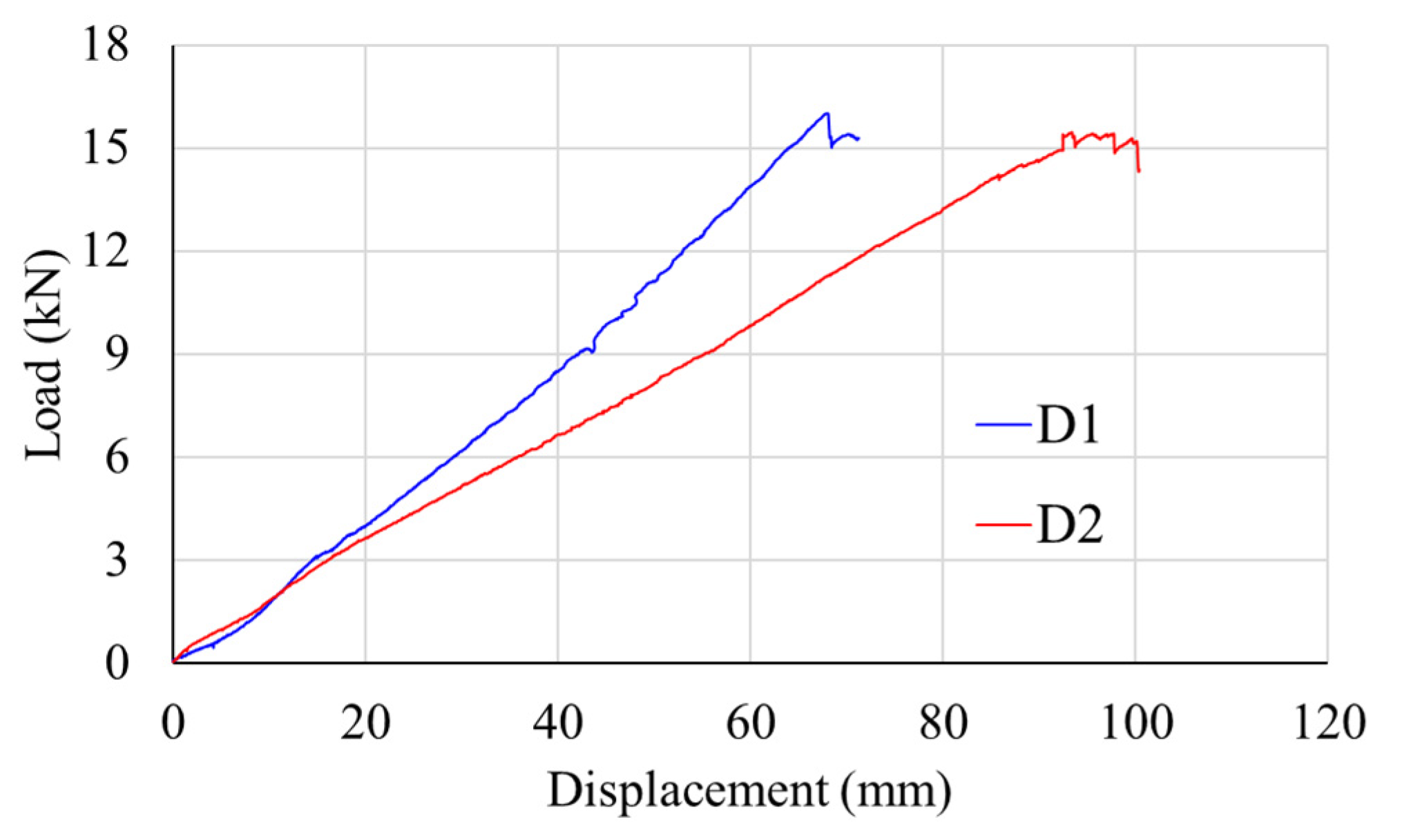
The two samples, D1 and D2, achieved an ultimate load of 16 kN and 15.43 kN at a deflection of 68.03 mm and 93.38 mm, respectively, illustrated in Figure 4. A linear increase in load is observed until the deck fails at the ultimate load. Due to bending at high deflections, minor local deformations on the deck are formed, and the deck cannot take any further load. A sudden load drop is seen at the ultimate load when deformations in the deck midspan occur. However, no significant local buckling is seen in the deck at these high deflection values. The external top hats are seen to be deformed inwards. A difference in the maximum displacement between D1 and D2 is noticed in the experimental results. When testing D1, the loading plates moved inwards towards the centre as the test proceeded, leaving the outer ribs unloaded at the later stages of the test. It reduced the displacement value of the entire deck, measured at the external support sheet. The movement of the support plates was stabilised in D2, where the loading plates were individually placed for each hydraulic loading point to ensure the loading of the entire deck. There is only a 3.6% difference between the ultimate loads determined in D1 and D2, which suggests that both tests are acceptable regarding the ultimate loads that are measured. At the same time, the displacement measurement of D2 is more stable than D1.
The construction stage load for the decks, as recommended by the AS 2327:2017 [25], is calculated at 9.4 kN. It includes the live load of 1 kN/m2 from the tools, machinery, and people and the dead loads from the deck, steel reinforcement, and fresh concrete. The obtained average ultimate load from the two experimental tests for the corresponding span is about 1.7 times higher than the value estimated based on AS 2327:2017. Hence the investigated deck design can be considered safe and suitable for construction.
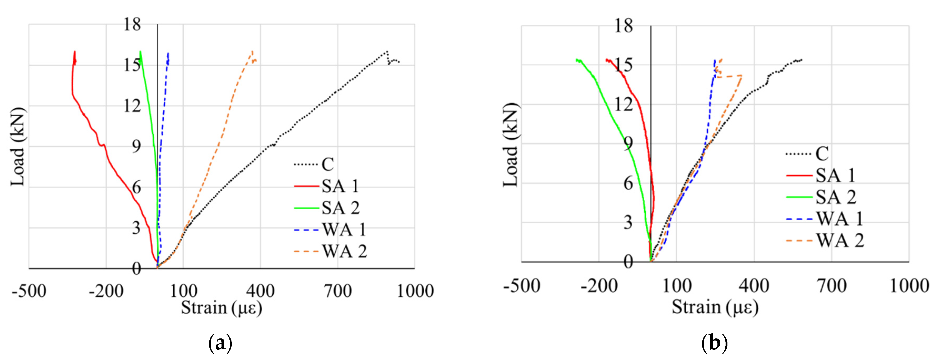
4.3. Strain Analysis
The load–strain curves shown in Figure 5. enable the analysis of the two-way load transfer. The tensile strain achieved at the ultimate load at the midspan, denoted as C, is high in D1 and D2 samples. However, the values obtained are much lower than the yield strain of the steel deck in both models, which indicates that the deck’s capacity was not fully utilised, and the yield strain was not reached. This is due to the steel deck’s sudden load drop caused by the local deformation failure on the base sheet. The bending at the centre of the deck occurs at high deflection, resulting in the deck being in higher tension at the centre than in the rest. It is reflected in the strains at the centre indicated as C.
Based on the position of the strain gauges shown in Figure 2c, the strain recorded on the top surface of the top hats forming the ribs is denoted as SA in Figure 5. In contrast, strain recorded along the weak direction on the bottom surface of the corrugated base sheet is designated as WA. At the ultimate load, the base sheet remains along the weak direction, whereas the ribs bend in compression along the strong direction at high loads. It can be observed that the compression strain development in the two SAs is uniformly mirrored with equal values in the corresponding WA, but in the WA case, it is maintained in tension. At ultimate load, comparable strain values are obtained for both the strong and weak axes. This indicates a uniform two-way action in the steel deck, where it can be determined that the deck efficiently distributes the loads in both directions. However, due to the movement of the loading plates in D1, the outer ribs were left unloaded during the test. It made the load distribution more prominent along WA2 and SA2 directions. This was resolved in D2, where the movement of the support plates was stabilised, thus presenting consistent load distribution along the symmetric directions.
The steady strain growth in the ribs and base sheet suggests that all the deck regions contribute equally to the transfer of loads without any significant local deformations or buckling on the deck. It could potentially establish a full-shear connection in a composite slab made with the deck until the yielding of the materials and thereby offering a sizeable longitudinal shear capacity. In a conventional composite slab, the decks are sensitive to early buckling due to the reduced width-to-thickness ratio resulting in a partial connection between the steel and concrete.
5. Finite Element Approach
ABAQUS software simulated a non-linear FE model of the tested experimental deck D2 due to the stability in the test setup and measurements. The plate movement during this test was more stable, resulting in a more accurate test setup and results. Only a quarter of the deck was modelled due to symmetry and reduced processing time.
5.1. Material Definition
The steel deck material was assumed to be elastic-perfectly plastic having the stress–strain behaviour acquired from experimental tests performed on tensile coupons taken from Lysaght’s CUSTOM ORB profile. This material primarily comprises steel with an average thickness of t = 0.42 mm. The material’s 0.2% offset yield stress was tested to be 722.5 MPa, and the density of steel components was 7850 kg/m3, as reported by Standards Australia [25]. The elastic modulus E and Poisson’s ratio ν were 200 GPa and 0.3 [26], respectively.
5.2. Modelling of Interaction, Boundary Conditions, and Loading
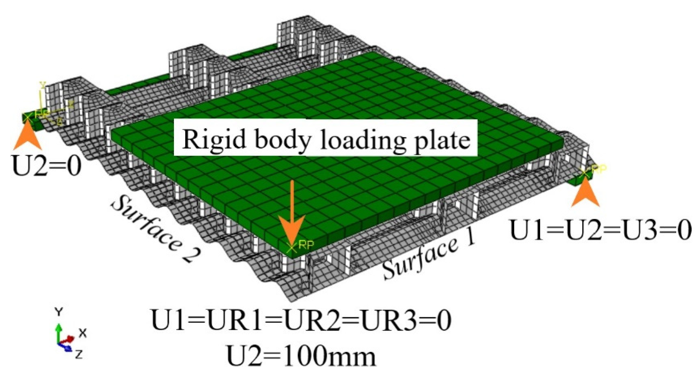
The test supports were defined as rigid bodies. The rigid bodies were fixed in the Y direction, allowing free rotation on all sides. A displacement of 100 mm in the Y-direction was applied through reference points acting on the rigid top plate, and the reaction force in the Y-direction was recorded. Hard contact was defined between the rigid body supports and the steel deck surface. Interaction between the support and deck was maintained through the loading stage by assuming a friction coefficient of 0.3 constant throughout all contact surfaces. Symmetric conditions were applied on the deck as shown in the setup in Figure 6, where the X-axis is perpendicular to the top hats, the Y-axis is along the depth of the slab, and the Z-axis is parallel to the top hats. Surface 1 is symmetric along the X-axis (U1 = UR2 = UR3 = 0), while Surface 2 is symmetric along the Z-axis (U3 = UR1 = UR2 = 0).
Geometric non-linearity was taken into account for large deflections in the analysed model. Before the non-linear analysis, an eigen buckling analysis was performed for each deck type to obtain the elastic buckling modes. The first buckling mode was used to analyse the initial geometric imperfection. A value of 0.1 t, considering 1% thickness variation, was used as the imperfection magnitude. Since local buckling had an insignificant influence, this value is sufficient to avoid numerical problems if imperfections are ignored.
5.3. Element Type and Mesh Definition
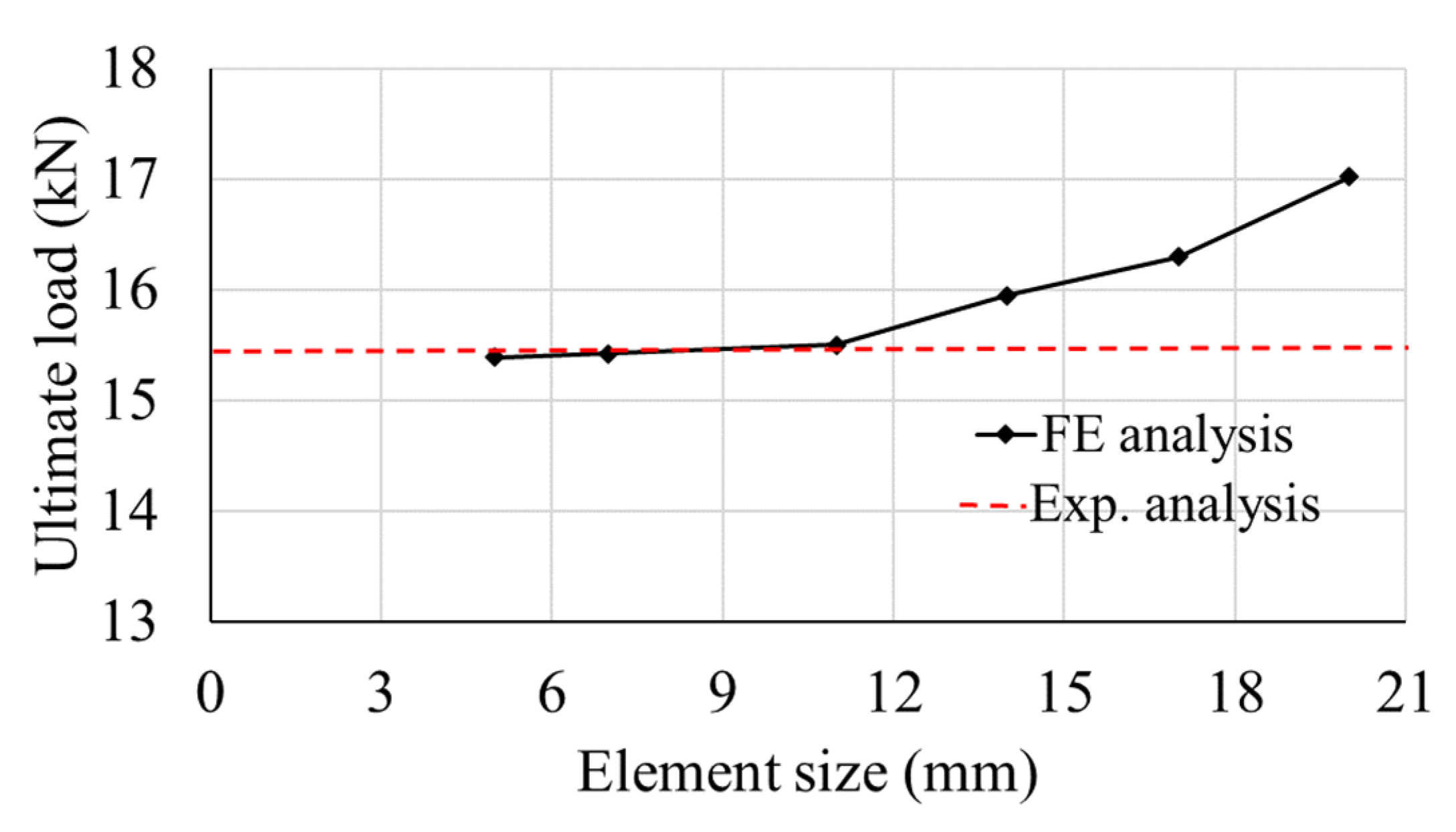
S4R shell elements with reduced integration were used for the steel deck. A convergence study for an optimum solution was conducted by reducing the number of elements while obtaining and maintaining accurate results. Figure 7 shows that the ultimate load of 15.43 kN of D2 was achieved close to 11 × 11 mm mesh size with less than a 5% difference in the values. Hence 11 mm meshes were chosen for the decks to achieve accurate results with reduced processing time.
6. FEA Model Validation and Parametric Study
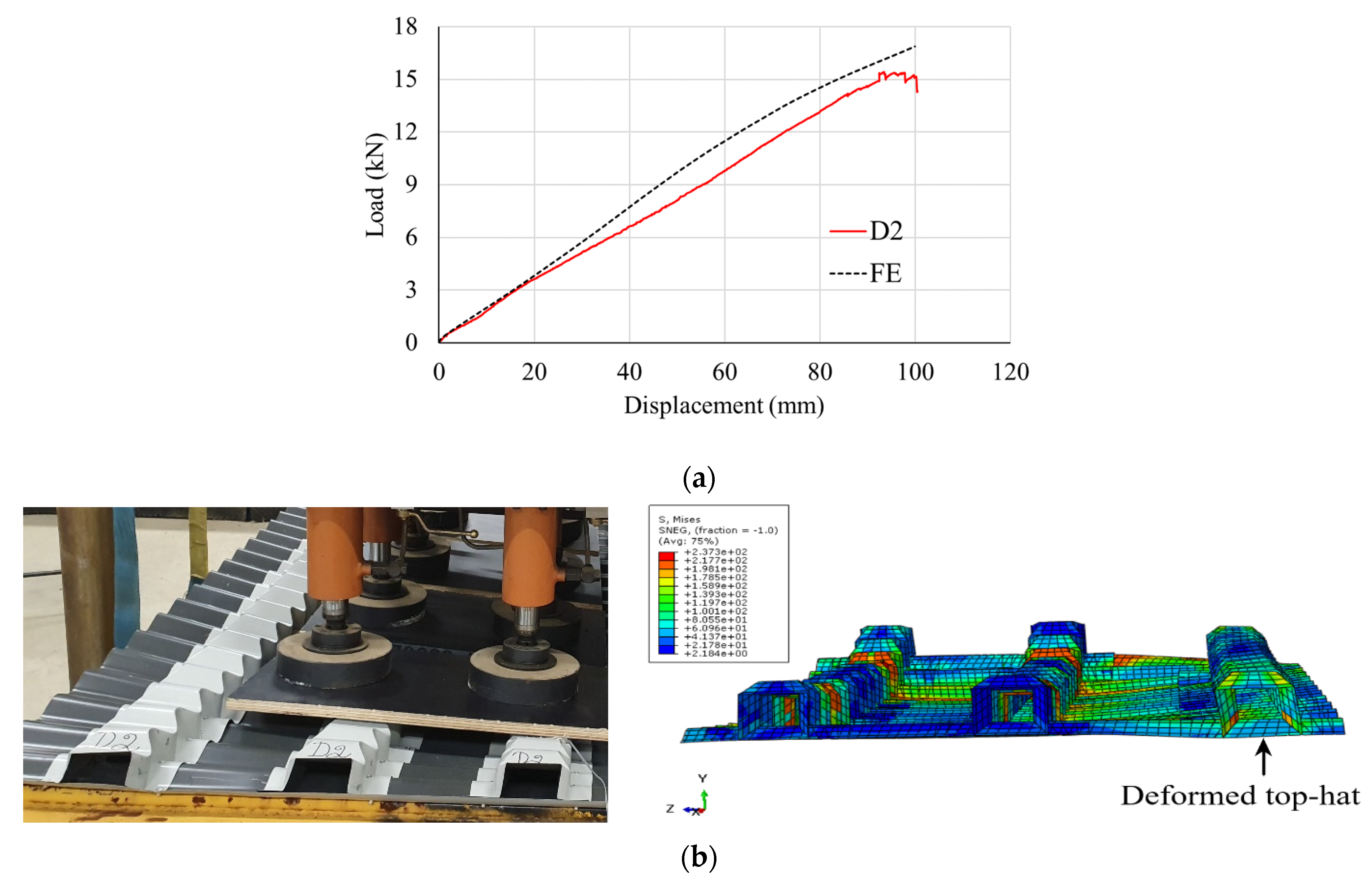
The load–displacement curves predicted by the FE were compared with the experimental results. The deviation was less than 5% for the new deck type in two-way behaviour. The failure of the decks in the experiments was primarily due to excessive deflection, with minor deformations in the corrugated base sheet. No buckling was observed, just as in the experimental test. As depicted by the load–displacement curve in Figure 8a and the failure modes in Figure 8b, the FE model predicts the observed behaviour of the new deck.
A study was conducted with four varying parameters on the verified FE model of the deck to understand the factors which affect the structural performance of the two-way deck system. The initial parameters involved varying the thickness of the corrugated base sheet and the thickness of the top-hat ribs. In contrast, the final parameter considered a deck type where a continuously connected top-hat rib system with and without a corrugated base sheet was considered for optimum performance. The load–displacement behaviour, two-way action, and failure mode will be identified for performance comparison.
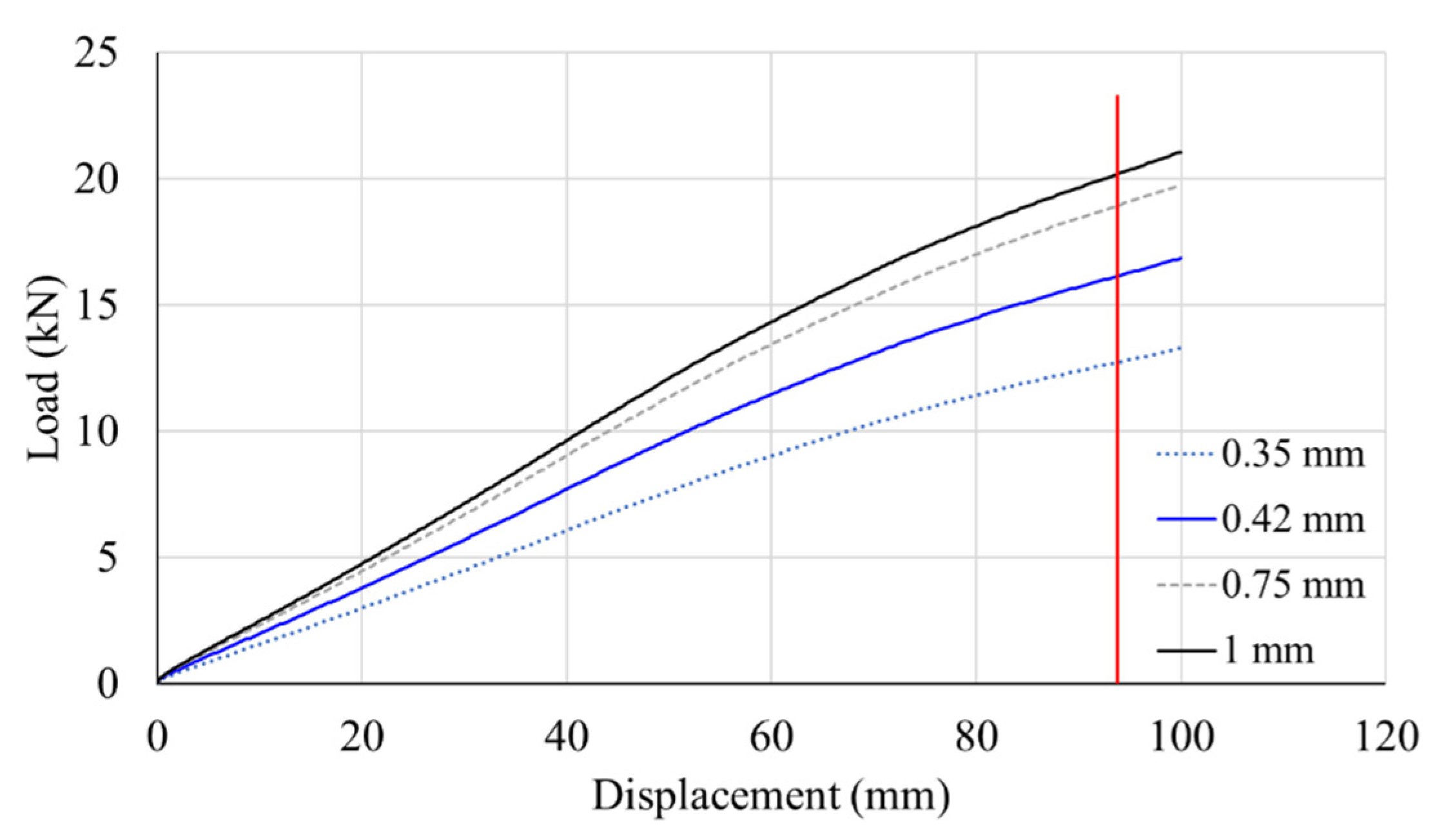
6.1. The Effect of Corrugated Base Sheet Thickness
A major study [27] concluded that the deck thickness is a significant governing parameter in the shear-bond capacity of composite slabs. Hence the deck thickness was varied in the current investigation to understand its influence on the behaviour of the new deck in composite construction. The corrugated base sheet’s thickness varied between 0.35 mm, 0.42 mm, 0.75 mm, and 1 mm, while the consistency of the top-hat ribs was maintained at the experimental sample thickness of 0.42 mm. It can be noticed from the load–displacement curves in Figure 9. that changing the thickness of the corrugated base sheet has a significant impact on the performance and behaviour of the two-way deck. In Figure 9, the vertical red line represents the ultimate load and deflection achieved from the experimental sample for the deck of 0.42 mm thickness. It can be seen that increasing the thickness of the corrugated base sheet between 0.35 mm, 0.42 mm, 0.75 mm and 1 mm increases the ultimate load capacity by 28.25%, 15.27%, and 6.78%, respectively. Therefore, the deck’s performance can be significantly improved by employing a thicker base corrugated sheet. The failure mode is the same as the tested panels with minor deformations of the top hats. It is also of note that no significant change to the transmission of two-way action was observed in the decks when the thickness of the corrugated base sheet was varied. The two-way load transmission was measured from the reaction forces along the strong and weak directions of the deck, which are 56% and 44%, respectively.
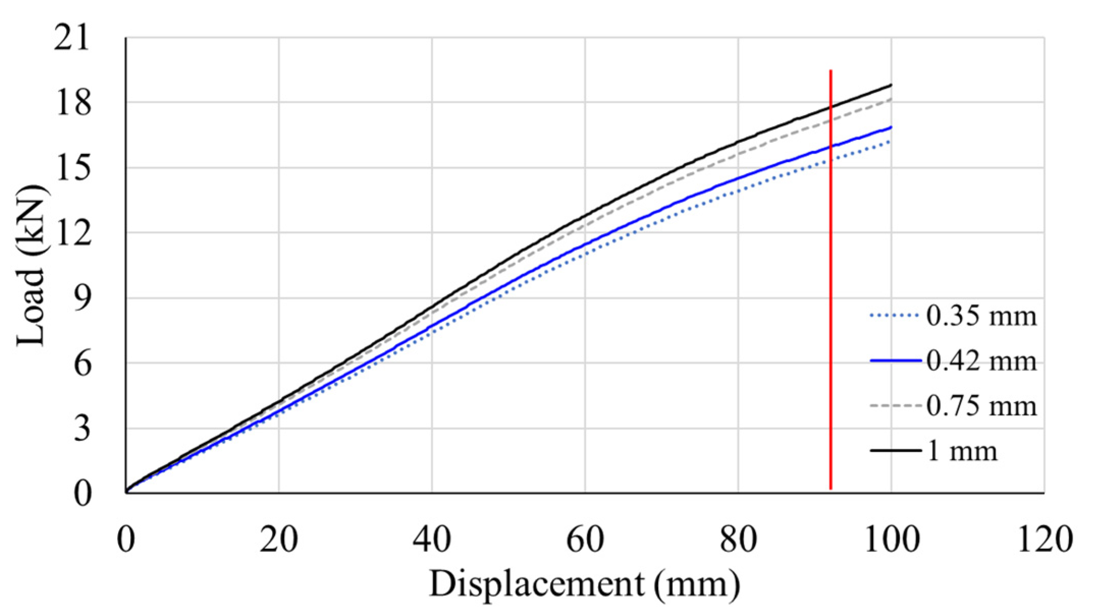
6.2. The Effect of Top-Hat Rib Thickness
Similar to the thickness values chosen for the corrugated base sheet, 0.35 mm, 0.42 mm, 0.75 mm, and 1 mm thick top-hat ribs were analysed for their performance, while the corrugated base sheet was now kept at a constant thickness of 0.42 mm. Only a minor increase in the load capacity was achieved, as seen in Figure 10. It is essentially due to the increase in moment of inertia of the top-hat ribs, which marginally reduces the bending in the strong direction. There was only an average increase of 5% between all the decks of varying top-hat rib thickness. The failure mode and two-way action were unaffected by the ribs’ thickness and remained constant throughout the samples.
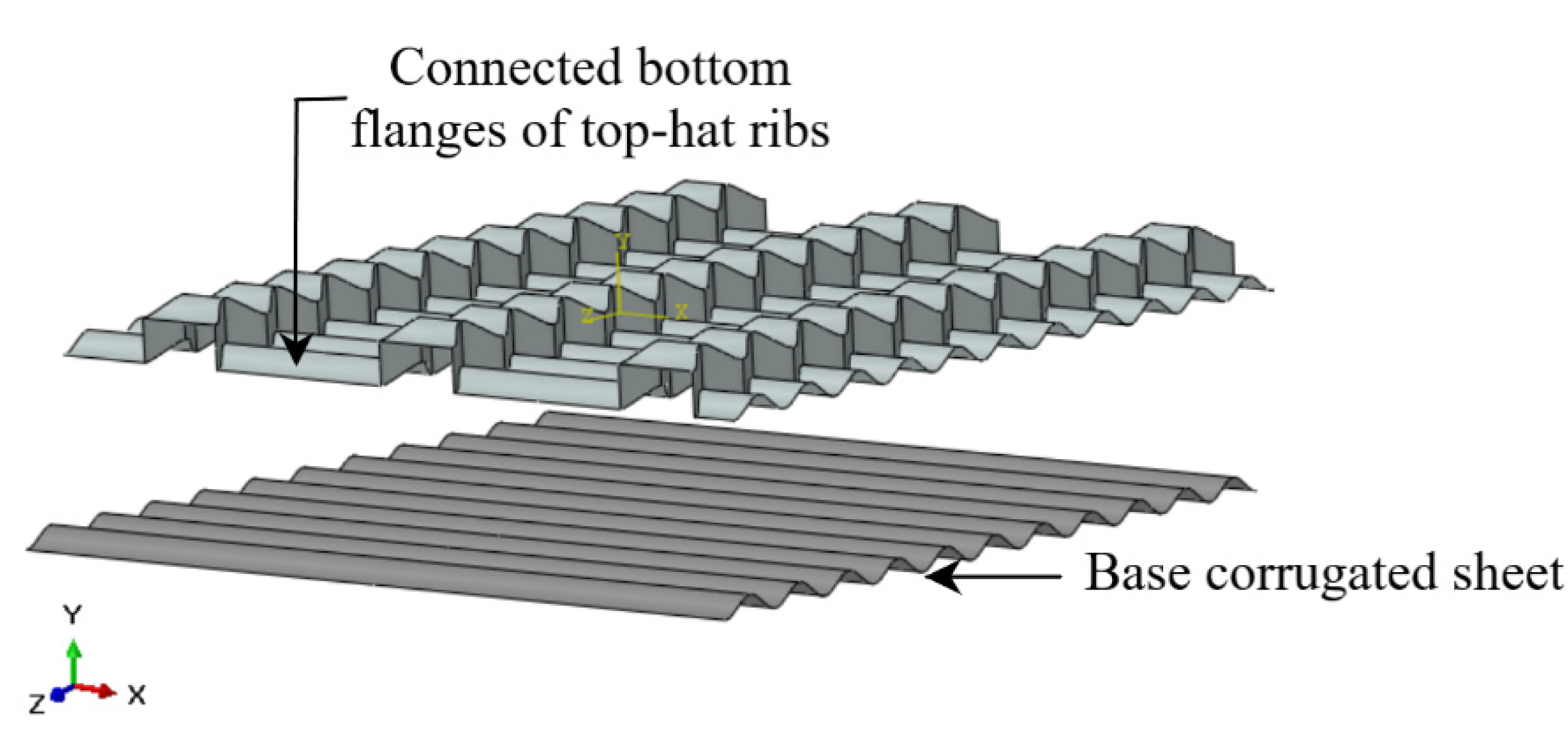
6.3. The Effect of a Connected Top-Hat Rib System with a Corrugated Base Sheet
The deck was modified so that the top-hat ribs were not performing individually, but a continuous formation of top hats was created to form a single deck. The bottom flanges are shared between two adjacent top hats, as depicted in Figure 11. However, in the experimental sample, the top hats were individually placed on the base sheet and disconnected from other top hats forming ribs. This was to check for improved two-action and load capacity due to a continuous system without any disruptions to load transfer. All the other properties of the deck were maintained the same as in the validated model.
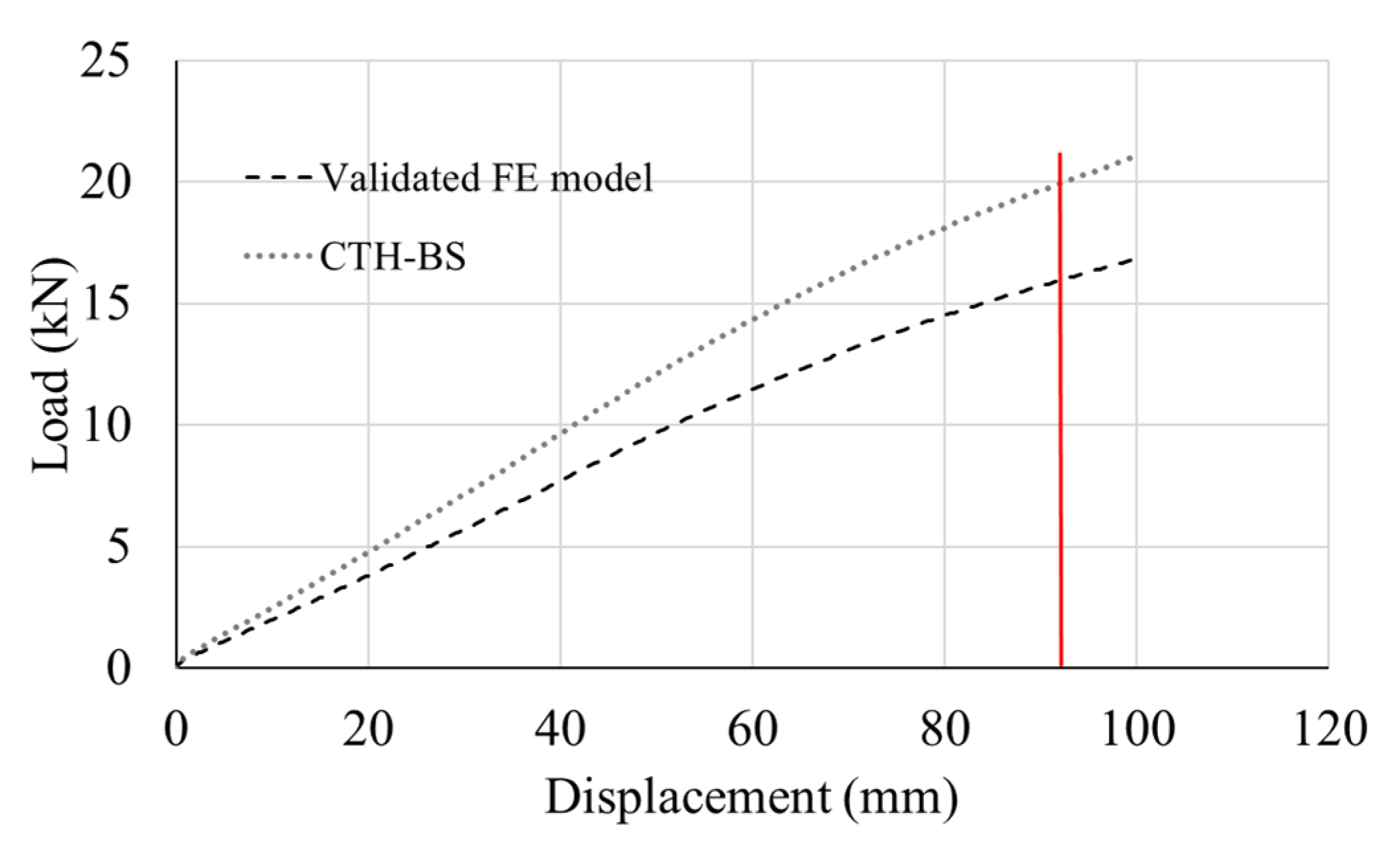
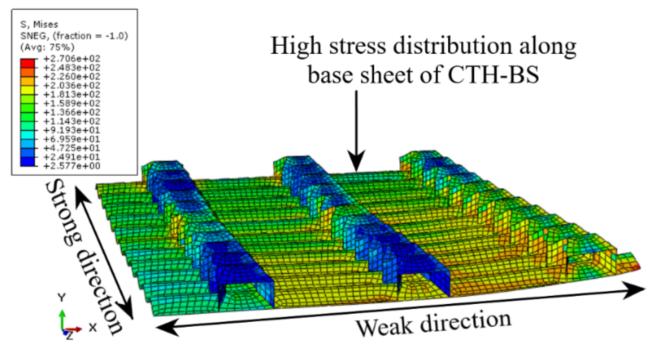
The connected flanges increase the stiffness of the two-way deck, which can be illustrated from the load–displacement curve comparison in Figure 12. The new parameter deck (CTH-BS) increased the load capacity to 19.51 kN in contrast to the validated FE model, which achieved a 15.51 kN ultimate load. Minor deformation concentrated on the outer top hat was observed at ultimate load while the top hats forming the inner ribs remained without distortions or deformations. The support reactions show that the two-way action is almost perfectly balanced at 47% in the weak direction and 53% in the strong direction at the ultimate load. A reaction force of 11 kN was recorded on the support for the strong direction or the top-hat ribs, and 8.5 kN reaction force was recorded along the base sheet support at the ultimate load. A more even distribution in two-way load was noticed in CTH-BS due to the continuous transfer of loads along the connecting flanges, evident from the high-stress distribution observed in the deck in Figure 13. However, in contrast to the experimental model, a load disruption in the deck’s weak direction is caused by the lack of continuity between the top-hat flanges resulting in a reduced load in the weak direction at ultimate load. The comparison of load distribution in each direction of the studied decks through the entire loading stage is depicted in Figure 14b.
However, it is worth noting that creating a continuous connected rib system with a corrugated base sheet increases the steel used in the deck system, increasing the system’s self-weight, while it may also be uneconomical. Further, the continuous system would also not influence the slab’s shear behaviour since it only contributes to the load capacity of the slab and creates no difference in the slab’s geometry at the interface.
6.4. The Effect of a Connected Top-Hat Rib System without a Corrugated Base Sheet
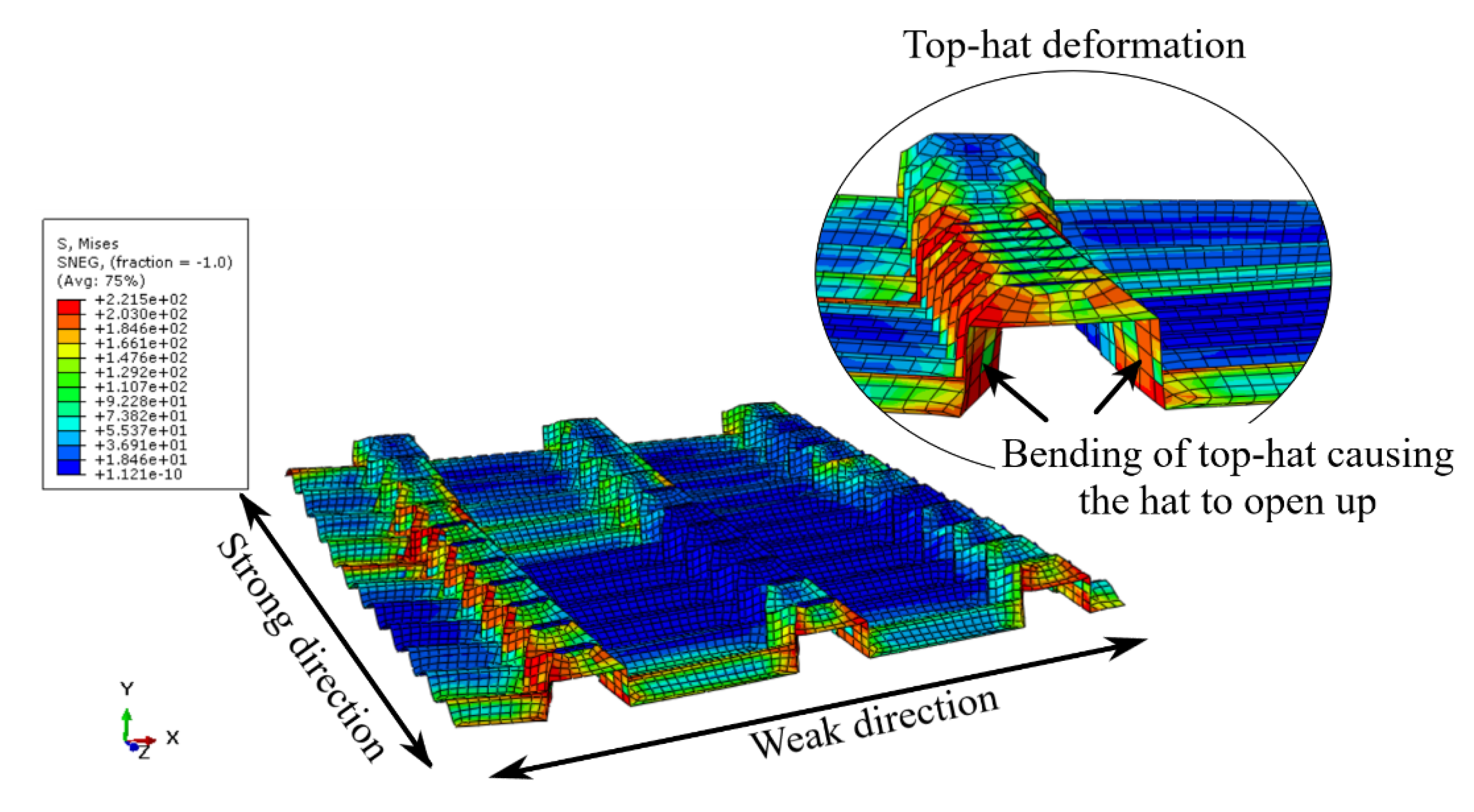
The continuously connected top-hat ribs were analysed without the corrugated base sheet to minimise the previous model’s material mass. The load displacement shows that the corrugated base sheet plays a significant role in load-carrying capacity. In the load–displacement curve in Figure 14a, the analysed deck is denoted as CTH. CTH is compared to the validated FE model and continuous connected top-hat ribs with base sheet indicated as CTH-BS as investigated earlier. The stiffness of CTH is 46% and 54% lower than the validated deck and CTH-BS, respectively. The load transfer in two-way action is also significantly affected by the absence of the corrugated base sheet in the analysed parameter. This is apparent from the low stresses observed along the weak direction of the deck, evident in Figure 15. The two-way action is also diminished, as seen in Figure 14b. The failure of the deck was attributed to the absence of a base sheet, as seen in Figure 15. The failure mode of the top hats could have caused a loss of interaction between the steel and concrete, resulting in vertical separation, causing shear failure.
7. Discussion
The FE model and the parametric study provide good insight into a composite slab developed two-way deck type. The main findings obtained from the study are reviewed in this section.
- (i)
- The role of the corrugated base sheet
It is evident from the parametric study that the corrugated base sheet plays a significant role in the ultimate load capacity and the two-way load distribution. In the absence of a corrugated base sheet, the two-way action in the CTH deck is reduced to 14.3% of the total load in the weak direction, as seen in Figure 14b. In this case, the CTH deck acts similarly to a conventional trapezoidal or re-entrant deck available in the market with limited load capacity and two-way behaviour. Additionally, the thickness of the corrugated base sheet positively influences the load capacity of the deck type (as seen in Figure 9). Earlier studies [14] to establish two-way action of commonly available composite decks have also shown the significance of employing a similar technique of steel straps on the base of the deck. Here, larger load capacity and two-way distribution are achieved with thicker straps. Therefore, from previous theories and the current study, it can be concluded that for two-way composite slab decks, base support is beneficial.
- (ii)
- The role of the top-hat sections
The top-hat sections serve as the ribs of the deck. Despite acting as the primary (strong) direction of the deck, the variation in thickness of these ribs has a negligible impact on the load-carrying capacity and the two-way behaviour of the deck (Figure 10). This behaviour is due to the geometry of the ribs. The buckling of ribs is a significant failure mode seen in traditional steel decks. Even at the small thickness of 0.42 mm of the ribs, no significant buckling was observed in the current ribs. This is ideal due to the corrugations on the top hats, which strengthen the geometry of the ribs. It results in the absence of buckling in these decks leading to almost constant and comparatively better load-carrying capacity regardless of the thickness of the top hats. To further improve the performance, connected bottom flanges of the top-hat ribs (CTH-BS deck) create a continuous transfer of loads along the connecting flanges. This altered rib system could contribute to a higher two-way and load capacity than the individual rib system.
8. Conclusions
This study aimed to investigate the performance of an innovative two-way steel deck for composite slabs in the construction stage. Both experimental and finite element methods were used to analyse the load–displacement, failure modes and two-way behaviour to assess the deck’s suitability for construction.
The experimental results show that the new two-way deck can provide even two-way loading through strong and weak directions while achieving an average ultimate load with no local buckling. The deck was also proven suitable and safe for construction under the loads from the construction stage. The behaviour and failure modes of the deck geometry suggest that it is ideal for composite construction due to the reduced buckling, which could potentially introduce a full shear connection in the slab.
ABAQUS software was used in the FE analysis to create and validate the FE models based on the experimental tests.
From the four parameters investigated, it was noticed that increasing the corrugated base sheet’s thickness can improve the two-way deck’s performance by an average of 16.7% between the analysed thicknesses. However, changing the thickness of the top-hat ribs has an insignificant effect of only a 5% increase in the load capacity with no other noticeable changes in two-way action or failure. Finally, it is essential to employ the right type of deck. It is understood that the corrugated base sheet plays a significant role in load distribution, and the continuously connected bottom flanges of the top hats create a more balanced two-way load distribution. The stiffness of the panels was improved by 54% when provided with a corrugated base sheet.
Further studies with concrete over the deck are necessary to evaluate the composite behaviour of the two-way deck. The composite floor will have improved behaviour and capacity due to the addition of the top-hat ribs, which will provide extra resistance against slip.
Author Contributions
Conceptualisation, K.J., M.A., M.W. and R.A.-A.; methodology, K.J.; validation, K.J.; formal analysis, K.J.; investigation, K.J.; resources, M.W.; writing—original draft preparation, K.J.; writing—review and editing, M.A., M.W. and R.A.-A.; supervision, M.A., M.W. and R.A.-A. All authors have read and agreed to the published version of the manuscript.
Funding
This research received no external funding.
Institutional Review Board Statement
Not applicable.
Informed Consent Statement
Not applicable.
Data Availability Statement
Data available from the corresponding author on request.
Acknowledgments
The authors acknowledge the technical support from industry partner FormFlow, Australia. The authors also thank Technical Staff, Lube Veljanoski and Michael Shanahan for completing the experimental investigation at Deakin University.
Conflicts of Interest
The authors declare no conflict of interest.
References
- Ahmed, I.M.; Tsavdaridis, K.D. The evolution of composite flooring systems: Applications, testing, modelling and eurocode design approaches. J. Constr. Steel Res. 2019, 155, 286–300. [Google Scholar] [CrossRef]
- Marimuthu, V.; Seetharaman, S.; Arul Jayachandran, S.; Chellappan, A.; Bandyopadhyay, T.K.; Dutta, D. Experimental studies on composite deck slabs to determine the shear-bond characteristic values of the embossed profiled sheet. J. Constr. Steel Res. 2007, 63, 791–803. [Google Scholar] [CrossRef]
- Ferrer, M.; Marimon, F.; Casafont, M. An experimental investigation of a new perfect bond technology for composite slabs. Constr. Build. Mater. 2018, 166, 618–633. [Google Scholar] [CrossRef]
- Degtyarev, V.V. Strength of composite slabs with end anchorages. Part II: Parametric studies. J. Constr. Steel Res. 2014, 94, 63–175. [Google Scholar] [CrossRef]
- Qureshi, J.; Lam, D.; Ye, J. The influence of profiled sheeting thickness and shear connector’s position on strength and ductility of headed shear connector. Eng. Struct. 2011, 33, 1643–1656. [Google Scholar] [CrossRef]
- Qureshi, J.; Lam, D.; Ye, J. Effect of shear connector spacing and layout on the shear connector capacity in composite beams. J. Constr. Steel Res. 2011, 67, 706–719. [Google Scholar] [CrossRef]
- Gholamhoseini, A.; Gilbert, R.I.; Bradford, M.A.; Chang, Z.T. Longitudinal shear stress and bond–slip relationships in composite concrete slabs. Eng. Struct. 2014, 69, 37–48. [Google Scholar] [CrossRef]
- Daniels, B.J.; Crisinel, M. Composite slab behavior and strength analysis. Part II: Comparisons with test results and parametric analysis. J. Struct. Eng. 1993, 119, 36–49. [Google Scholar] [CrossRef]
- Avudaiappan, S.; Saavedra Flores, E.I.; Araya-Letelier, G.; Jonathan Thomas, W.; Raman, S.N.; Murali, G.; Amran, M.; Karelina, M.; Fediuk, R.; Vatin, N. Experimental investigation on composite deck slab made of cold-formed profiled steel sheeting. Metals 2021, 11, 229. [Google Scholar] [CrossRef]
- Ferrer, M.; Marimon, F.; Crisinel, M. Designing cold-formed steel sheets for composite slabs: An experimentally validated FEM approach to slip failure mechanics. Thin-Walled Struct. 2006, 44, 1261–1271. [Google Scholar] [CrossRef]
- Dar, M.A.; Subramanian, N.; Dar, A.; Ghowsi, A.F.; Sidiqui, F.; Fayaz, S.; Mir, M.S. Comparison of various shear connectors for improved structural performance in CFS concrete composite slabs. Eng. Struct. 2020, 220, 111008. [Google Scholar] [CrossRef]
- Porter, M.L. Analysis of two-way acting composite. J. Struct. Eng. 1985, 111, 1–18. [Google Scholar] [CrossRef]
- Porter, M.L. The Behavior and Analysis of Two-Way Simply Supported Concrete Composite Floor Slabs Constructed with Cold-Formed Steel Decking; Iowa State University: Ames, IA, USA, 1974. [Google Scholar]
- Eldib, M.E.; Maaly, H.M.; Beshay, A.W.; Tolba, M.T. Modelling and analysis of two-way composite slabs. J. Constr. Steel Res. 2009, 65, 1236–1248. [Google Scholar] [CrossRef]
- Ahmed, E.; Badaruzzaman, W.W.; Wright, H. Two-way bending behavior of profiled steel sheet dry board composite panel system. Thin-Walled Struct. 2002, 40, 971–990. [Google Scholar] [CrossRef]
- FormFlow. 2020. Available online: https://formflow.net.au. (accessed on 3 January 2020).
- Arrayago, I.; Real, E.; Mirambell, E.; Marimon, F.; Ferrer, M. Experimental study on ferritic stainless steel trapezoidal decks for composite slabs in construction stage. Thin-Walled Struct. 2019, 134, 255–267. [Google Scholar] [CrossRef]
- John, K.; Ashraf, M.; Weiss, M.; Al-Ameri, R. Experimental investigation of novel corrugated steel deck under construction load for composite slim-flooring. Buildings 2020, 10, 208. [Google Scholar] [CrossRef]
- Hofmeyer, H.; Kerstens, J.; Snijder, H.; Bakker, M. Combined web crippling and bending moment failure of first-generation trapezoidal steel sheeting. J. Constr. Steel Res. 2002, 58, 1509–1529. [Google Scholar] [CrossRef]
- John, K.; Rahman, S.; Kafle, B.; Weiss, M.; Hansen, K.; Elchalakani, M.; Udawatta, N.; Hosseini, M.R.; Al-Ameri, R. Structural Performance Assessment of Innovative Hollow Cellular Panels for Modular Flooring System. Buildings 2022, 12, 57. [Google Scholar] [CrossRef]
- Rahman, S.; John, K.; Kafle, B.; Al-Ameri, R. Structural Performance of Modular Sandwich Composite Floor Slabs Containing Basalt FRP-Reinforced Self-Compacting Geopolymer Concrete. Appl. Sci. 2022, 12, 4246. [Google Scholar] [CrossRef]
- ABAQUS; Version 6.14; Standard User’s Manual. Dassault Systèmes Simulia Corp: Providence, RI, USA, 2014.
- Mistakidis, E.S.; Dimitriadis, K.G. Bending resistance of composite slabs made with thin-walled steel sheeting with indentations or embossments. Thin-Walled Struct. 2008, 46, 192–206. [Google Scholar] [CrossRef]
- LYSAGHT. 2021. Available online: https://www.lysaght.com/products/customflow (accessed on 15 April 2021).
- AS:2327-2017; Composite Structures—Composite Steel-Concrete Construction in Buildings. Standards Australia: Sydney, NSW, Australia, 2017.
- Bergengren, Y.; Melander, A. An experimental and theoretical study of the fatigue properties of hot-dip-galvanized high-strength sheet steel. Int. J. Fatigue 1992, 14, 154–162. [Google Scholar] [CrossRef]
- Seleim, S.S.; Schuster, R.M. Shear-bond resistance of composite deck-slabs. Can. J. Civ. Eng. 1985, 12, 316–324. [Google Scholar] [CrossRef]
Figure 1.
Two-way steel deck system. (a) Cross-section dimensions of two-way deck system. (b) Corrugated top-hat rib section. (c) Assembled two-way deck. (d) Mechanism of shear bond in new deck profile.
Figure 1.
Two-way steel deck system. (a) Cross-section dimensions of two-way deck system. (b) Corrugated top-hat rib section. (c) Assembled two-way deck. (d) Mechanism of shear bond in new deck profile.

Figure 2.
Test setup. (a) Experimental setup and loading. (b) Schematic of the test setup. (c) Strain gauge positions.
Figure 2.
Test setup. (a) Experimental setup and loading. (b) Schematic of the test setup. (c) Strain gauge positions.

Figure 3.
Failure modes of two-way deck system. (a) Failed deck with deformed top-hats. (b) Local deformations seen on a corrugated base sheet at supported points. (c) Minor local deformations on the corrugated base sheet at ultimate load.
Figure 3.
Failure modes of two-way deck system. (a) Failed deck with deformed top-hats. (b) Local deformations seen on a corrugated base sheet at supported points. (c) Minor local deformations on the corrugated base sheet at ultimate load.

Figure 4.
Load-displacement curves.

Figure 5.
Load-strain curves (a) D1 sample, (b) D2 sample.

Figure 6.
Symmetric FE model of the tested two-way deck.

Figure 7.
Mesh convergence study of the two-way deck.

Figure 8.
Validation of FE model results. (a) Load-displacement comparison of experimental result and FE result. (b) Failure mode comparison of the experimental deck and FE deck model.
Figure 8.
Validation of FE model results. (a) Load-displacement comparison of experimental result and FE result. (b) Failure mode comparison of the experimental deck and FE deck model.

Figure 9.
Load–displacement curves for decks of varying thickness of the corrugated base sheet.

Figure 10.
Load–displacement curves for decks of varying thickness of top-hat ribs.

Figure 11.
Continuous bottom flanges of top hats placed on a corrugated base sheet.

Figure 12.
Load–displacement curve comparison for decks with connected bottom flanges of top-hat ribs.
Figure 12.
Load–displacement curve comparison for decks with connected bottom flanges of top-hat ribs.

Figure 13.
Failed CTH-BS deck with high stress along base sheet indicating higher load distribution along the weak direction.
Figure 13.
Failed CTH-BS deck with high stress along base sheet indicating higher load distribution along the weak direction.

Figure 14.
(a) Load-displacement curve comparison for decks of connected bottom flanges of top-hat ribs in the absence of corrugated base sheet, (b) Percentage load distributed along each direction of the deck through the entire loading stage.
Figure 14.
(a) Load-displacement curve comparison for decks of connected bottom flanges of top-hat ribs in the absence of corrugated base sheet, (b) Percentage load distributed along each direction of the deck through the entire loading stage.

Figure 15.
Failure of CTH deck type.

Publisher’s Note: MDPI stays neutral with regard to jurisdictional claims in published maps and institutional affiliations. |
© 2022 by the authors. Licensee MDPI, Basel, Switzerland. This article is an open access article distributed under the terms and conditions of the Creative Commons Attribution (CC BY) license (https://creativecommons.org/licenses/by/4.0/).
Share and Cite
MDPI and ACS Style
John, K.; Ashraf, M.; Weiss, M.; Al-Ameri, R. Experimental and Finite Element Study of a Novel Two-Way Corrugated Steel Deck System for Composite Slabs. J. Compos. Sci. 2022, 6, 261. https://doi.org/10.3390/jcs6090261
AMA Style
John K, Ashraf M, Weiss M, Al-Ameri R. Experimental and Finite Element Study of a Novel Two-Way Corrugated Steel Deck System for Composite Slabs. Journal of Composites Science. 2022; 6(9):261. https://doi.org/10.3390/jcs6090261
Chicago/Turabian StyleJohn, Keerthana, Mahmud Ashraf, Matthias Weiss, and Riyadh Al-Ameri. 2022. "Experimental and Finite Element Study of a Novel Two-Way Corrugated Steel Deck System for Composite Slabs" Journal of Composites Science 6, no. 9: 261. https://doi.org/10.3390/jcs6090261