
Modeling Intruder Reconnaissance Behavior through State Diagrams to Support Defensive Deception

1
Department of Computer Science and Biomedical Informatics, University of Thessaly, 35131 Lamia, Greece
2
Department of Information Security and Communication Technology, Norwegian University of Science and Technology, NO-2815 Gjovik, Norway
*
Author to whom correspondence should be addressed.
J. Cybersecur. Priv. 2023, 3(2), 275-302; https://doi.org/10.3390/jcp3020015
Submission received: 15 April 2023
/
Revised: 27 May 2023
/
Accepted: 6 June 2023
/
Published: 14 June 2023
(This article belongs to the Section Security Engineering & Applications)
Abstract
:Active reconnaissance is the primary source of information gathering about the infrastructure of a target network for intruders. Its main functions are host discovery and port scanning, the basic techniques of which are thoroughly analyzed in the present paper. The main contribution of the paper is the definition of a modeling approach regarding (a) all possible intruder actions, (b) full or partial knowledge of the intruder’s preferred methodology, and (c) the topology of the target network. The result of the modeling approach, which is based on state diagrams, is the extraction of a set of all probable paths that the intruder may follow. On top of this, a number of relevant metrics are calculated to enable the dynamic assessment of the risk to specific network assets according to the point on the paths at which the intruder is detected. The proposed methodology aims to provide a robust model that can enable the efficient and automated application of deception techniques to protect a given network. A series of experiments has also been performed to assess the required resources for the modeling approach when applied in real-world applications and provide the required results with bearable overhead to enable the online application of deception measures.
1. Introduction
Network security is a broad term that includes mechanisms designed to protect the devices, users, and applications on computer networks and the integrity, confidentiality, and availability of data. Due to the importance of computer networks in recent years, network security mechanisms have become indispensable for any system.
Usually, carrying out an attack consists of the following steps. Initially, the intruder tries to gather as much information about the target system as possible from sources such as the target’s website, search engines, social media, or publicly available sources (e.g., Shodan). This stage is called passive reconnaissance and the intruder identifies the IP addresses of the hosts of the target infrastructure. The next step is to investigate what services are running on these hosts. This is achieved by using port scanning reconnaissance and this stage is called active reconnaissance because the intruder interacts with the target’s machines.
The intruder will then try to gain access to the target machine by exploiting vulnerabilities that may exist in some of the services. After that, they will try to escalate their privileges and install persistent remote access mechanisms.
Subsequently, the intruder will perform active reconnaissance in the internal network to which he has gained access by using the host as a starting point (lateral movement). As we can observe, the first step always requires gathering information on the target to identify weak points of the targeted system. Therefore, the active reconnaissance stage is quite important and is repeated several times during an attack.
Active information gathering consists of two main elements: host discovery and port scanning. Host discovery is the process that identifies what hosts are running in a network. Host discovery in network scanning is often the first step used by intruders before they execute an attack. Port scanning is the process of identifying port availability by sending connection requests to a target computer and recording which ports respond and how. Determining which ports are in use enables intruders to determine which applications and services are active on the target machine. From there, as described in [1], an intruder can check for vulnerabilities and begin to plan an attack. Other techniques that intruders may use such as banner scanning and OS fingerprinting are based on the interpretation of the results obtained by host discovery and port scanning and the relevant activity can actually be modeled through the same approach.
Host discovery and port scanning reconnaissance can be achieved through a number of available protocols, such as ICMP, TCP, and UDP, depending on the target’s environment, such as the existence of a firewall. Details on the implementation of the above reconnaissance techniques are analyzed in Section 3.
As reconnaissance is the first step of most attack plans, it is highly significant to provide tools and methodologies aiming at the fast and accurate detection of it, along with the mitigation of it or the minimization of the obtained knowledge for the intruder. There are numerous efforts in the literature that discuss network security detection and mitigation mechanisms that include, among others, the reconnaissance step of the attack. However, research efforts focusing solely on reconnaissance are very limited in number. The present paper focuses on the reconnaissance step of network attacks and mainly on modeling the process. The proposed methodology provides a robust and detailed representation of the intruders’ activity during the reconnaissance step of an attack according to the structure of the network and the intruder’s knowledge methodology (potentially incomplete). The proposed approach uses hierarchical state diagrams to represent possible intruders’ actions/decisions, producing a set of different paths that the intruder may follow. On those paths, a number of metrics are calculated with respect to the probability that the intruder obtains or does not obtain specific information about the network, along with the estimated time until this happens.
The contributions of the present paper are the following:
- A hierarchical set of state diagrams that model all different actions of an intruder during reconnaissance.
- A flexible syntax to model the protected network structure and existing partial knowledge about the methods an intruder follows.
- An algorithm that uses the previously mentioned models to produce a set of possible attack paths an intruder may follow.
- The definition of metrics for the probability that an intruder obtains a specific piece of information and for the number of steps required to do so.
It has to be noted that the proposed methodology is part of a wider research effort to construct an automated deception mechanism that will mitigate reconnaissance in a network. The present paper is the first step towards that goal and sets the foundation for modeling and measuring the reconnaissance activity to apply deception techniques to mitigate it. To the extent of our knowledge, there is no other systematic approach to model the behavior of an attacker during the reconnaissance step of an attack and we hope that this work serves as the basis for multiple future research efforts regarding network reconnaissance.
As mentioned above, this paper forms the basis of a mechanism to deceive an intruder. By knowing all the possible paths for host discovery techniques for a computer network, we can influence the attacker to take different paths before they reach their target. By applying deception techniques, we can achieve the following:
- 1.
- Increase the intruder’s workload;
- 2.
- Allow defenders to better track attacks and respond before adversaries succeed;
- 3.
- Exhaust adversary resources;
- 4.
- Increase the sophistication required for an attack;
- 5.
- Increase the intruder’s uncertainty.
This paper is structured as follows. Section 2 presents related work in the fields of host discovery and port scanning operations. In Section 3, the main techniques for host discovery and port scanning reconnaissance activities are presented. In Section 4, our modeling approach that aims at enabling a detailed representation of an intruder’s reconnaissance activity is presented. In Section 5, an implementation based on the model described in Section 4 is presented. In Section 6, we performed a series of experiments in order to find out how fast the mechanism described in Section 5 produces its results. Finally, Section 7 presents our conclusions and our future work based on this paper.
2. Related Work
There are not any efforts in the literature that attempt to directly model the reconnaissance activity and provide a state-of-the-art comparison for the present paper. The most relevant domain that can provide useful input to our work is reconnaissance detection, as it is based on modeling the actual behavior of the intruder we target. Various approaches exist in the literature regarding the detection of the existence of an intruder during host discovery and port scanning operations. These are analyzed in the present section, but no direct comparison is feasible.
Haan in [2] discussed approaches for the detection of port scans using IP header data. Through their work, they provided a knowledge basis for port scanning, such as scan types, scan techniques, and hiding scanner identity methods. In addition, different port scanning detection approaches were tested and detection via IP header data was proposed as the optimal solution.
Patel et al. in [3] proposed a Rule-Based Network Intrusion Detection System for port scanning with efficient port scan detection rules using snort. Through their work, they provided a basis for port scanning attacks and additionally, they proposed a rule-based network IDS which examines ongoing traffic, transactions, activity, or behavior for matches with known patterns of events specific to known attacks.
Vivo et al. in [4] provided a review of port scanning techniques. Specifically, they analyzed the most important techniques used by TCP port scanners. Vugrin et al. in [5] introduced a novel mathematical model that describes the port scanning progress of an intruder and intrusion detection by a defender. Their work further describes a set of emulation experiments that was conducted with a virtual test bed and used to validate the model.
Ananin et al. in [6] proposed port scanning detection based on network anomalies. Specifically, they reviewed the type of network anomalies (produced by port scans), the main types of port scans, and the peculiarities of the implementation of various types of scans. These data were used to construct a mathematical model and an algorithm for detecting anomalies caused by port scanning.
Bhuyan et al. in [7] provided a survey for port scans and their detection methodologies. Through their work, they introduced port scanning technologies and presented a variety of port scanning detection approaches. Barnett et al. in [8] presented a classification of network scanning and illustrated how complex and varied this activity is. The presented classification extends previous well-known definitions of scanning traffic in a manner that reflects this complexity. Lee et al. in [9] proposed the detection and characterization of port scan attacks. They analyzed and characterized port scanning traffic by defining a set of heuristics and applying them to the network trace data. They were able to isolate suspicious packets and group them into sets of scans. In addition, these sets were further analyzed to extract the properties of the port scanning traffic and to collect relevant statistics.
Kanlayasiri et al. in [10] provided a rule-based approach for port scanning detection. Their work presented a method for detecting port scanning attacks using rule-based state diagram techniques. Specifically, a set of rules corresponding with the appropriate thresholds was designed for intrusion decisions. Additionally, the experimental results under real environments showed that port scanning patterns were detected in real time successfully.
Doynikova et al. in [11] provided a comparative review of attacker behavior forecasting methods. The goal of their work was to analyze existing techniques such as (a) techniques based on attack graph analyses, (b) techniques based on the hidden Markov model, (c) techniques based on fuzzy inference, and (d) techniques based on attributing cyber attacks using intelligent data mining techniques, including neural networks, statistics, and so on. In addition, the attackers’ profile specifications as well as the application of such specifications for the forecasting of the attack’s future steps were analyzed.
Katipally et al. in [12] proposed an attacker behavior analysis approach for a multi-stage attack detection system. Specifically, a hidden Markov model (HMM) was used in order to analyze and predict the attacker’s behavior based on what was learned from observed alerts and intrusions. In addition, data mining was used to process alerts and generate the input for the HMM in order to calculate the required probability distribution.
Soniya et al. in [13] proposed a detection mechanism of TCP SYN scanning using packet counts and neural networks. Specifically, their work investigated the effectiveness of using counts of various TCP control packets in detecting TCP SYN scanning on a single computer. Additionally, the behavioral characteristics of TCP control packets were aggregated to train a neural network with normal and port scanning data.
Trassare et al. in [14] proposed a technique for network topology deception. Through their research, they analyzed a novel methodology based on the principles of military deception for deceiving malicious trace routes by changing the structure of a network. Moreover, they implemented a topology deception kernel module for a Linux router. The module inspects traffic at the network ingress and identifies inbound UDP trace route probes, for which it then generates spoofed replies to provide the illusion of any topology the deceiver chooses.
Albanese et al. in [15] proposed an approach to defeat an intruder’s fingerprinting effort through deception. In order to defeat OS fingerprinting, they manipulated outgoing traffic so that it resembles traffic generated by a host with a different operating system. Similarly, to defeat service fingerprinting, they modified the service banner by intercepting and manipulating certain packets before they leave the host or network.
Malecot in [16] introduced a defense mechanism with the purpose of mitigating the benefits an attacker expects from scanning a targeted network. Specifically, this mechanism acts against scanning activity by continuously obfuscating the appearance of the targeted network through a combination of various simple mechanisms, such as traffic forging and random connection dropping. In addition, a method to penalize hosts sending suspicious traffic to the targeted network was proposed.
Lee et al. in [17] implemented tools for stealth port scans, such as NULL, FIN, Xmas and ACK, using ZMap, which is part of Censys search engine, and tested the vulnerability of devices in a university network using the implemented tools. As a result, it was observed that it is possible to identify basic information of the hosts, such as port states, services, configurations, and OSs.
Dabbagh et al. in [18] presented a method for detecting slow port scans. Their method is mainly composed of two phases: (a) a feature collection phase that analyzes the network traffic and extracts the features needed to classify a certain IP as malicious or not and (b) a classification phase that divides the IPs into three groups based on the collected features: normal IPs, suspicious IPs, and scanner IPs. The IPs that are classified as suspicious are kept for a specified number of time windows for further examination to decide whether they belong to scanners or to legitimate users. The experimental results showed the effectiveness of this approach in correctly classifying IPs and detecting normal and slow port scanning attempts.
Gadge et al. in [19] designed a system to detect port scan attempts and at the same time find out information about the machine from which the port scan attempts originate, such as the operating system or location.
Algaolahi et al. in [20] proposed port scanning attack detection using supervised machine learning classifiers. Specifically, their study focused on detecting port scanning attacks by using different machine learning algorithms and comparing them to find the best one. Some algorithms, such as Decision Tree and Random Forest, achieves almost 100% accuracy in detecting these types of attacks, even with short training periods.
Pham et al. in [21] proposed a novel model to capture how advanced, stealthy adversaries acquire knowledge about the target network and establish and expand their foothold within the system. From the adversary’s perspective, this model quantifies the cost and reward of compromising and maintaining control over target nodes. They evaluated this model through simulations in CyberVAN and indicated how it can guide the development and deployment of future defensive capabilities, including high-interaction honeypots, to influence adversaries’ behavior and steer them away from critical resources.
Steingartner et al. in [22] introduced deception technology and the cyber attack cycle, as well as an overview of detection, in order to create an active defense. Through their work, they showed how deception fits within the overall security architecture and designed the conceptual Hybrid Threats Model and military education for cyber-security, as well as describing the role it plays in detecting, identifying, and responding to threats. Furthermore, they emphasized that deception should be used strategically to stop advanced attackers.
3. Background
Port scanning is a method for determining which ports are active on a computer system. Ports can be assigned to services and they are numbered from 0 to 65,535, but certain ranges are more frequently used. Ports 0 to 1023 are identified as the “well-known ports“, or standard ports, and have been assigned to specific services by the Internet Assigned Numbers Authority (IANA). Running a port scan on a network reveals which ports are open and listening (receiving information), as well as the presence of security devices such as firewalls that are present between the intruder and the target.
Intruders may be driven by different motivations to conduct port scanning. The set of IP addresses and ports (sockets) that are probed in a scan is called a scan’s footprint. Three types of footprint are commonly distinguished:
- Horizontal scansFocus on probing two or more hosts for one specific port. This type of scan footprint is common when an intruder has knowledge of how to exploit a particular vulnerability and is in search of a vulnerable host.
- Vertical scans focus on probing one host for a larger set of ports. This occurs when an intruder’s interest is mapping all potential vulnerabilities of one particular host.
- Block scans are both horizontal and vertical, probing a large number of ports on more than one host.
On the basis of how port scanning is performed, port scan techniques can be classified into two main categories:
- Single source port scans, where the intruder can scan the network in a one-to-many model;
- Distributed port scans, where information gathering is performed using either a many-to-one or a many-to-many model.
Scan techniques
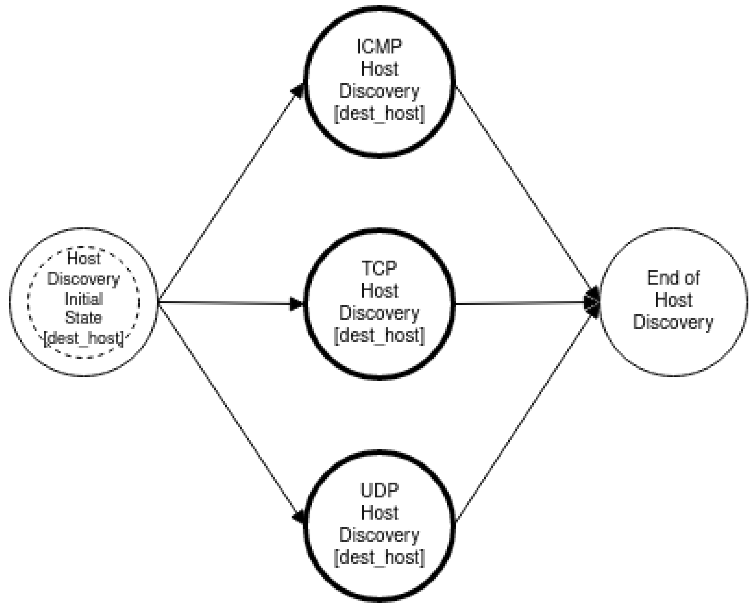
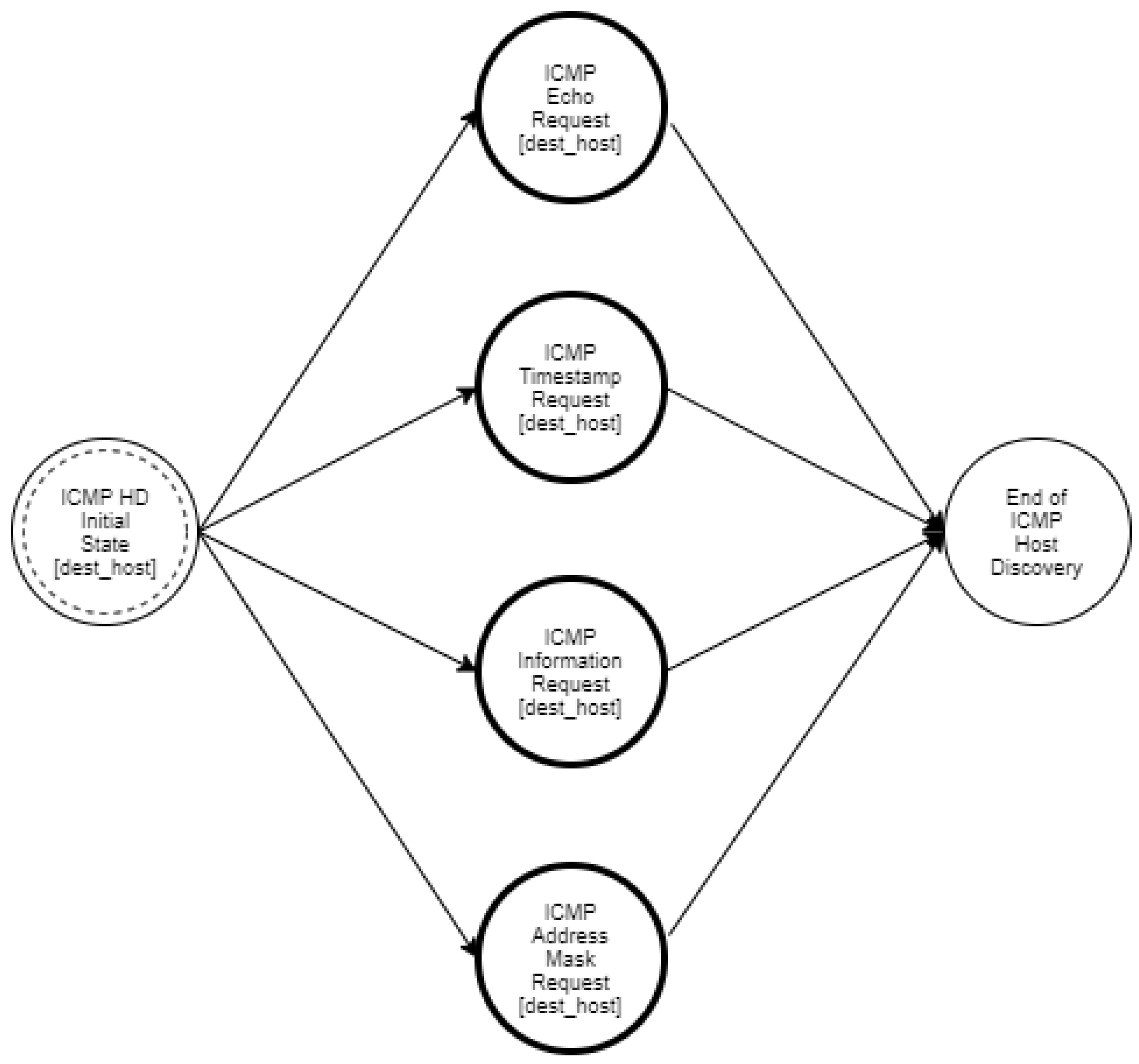
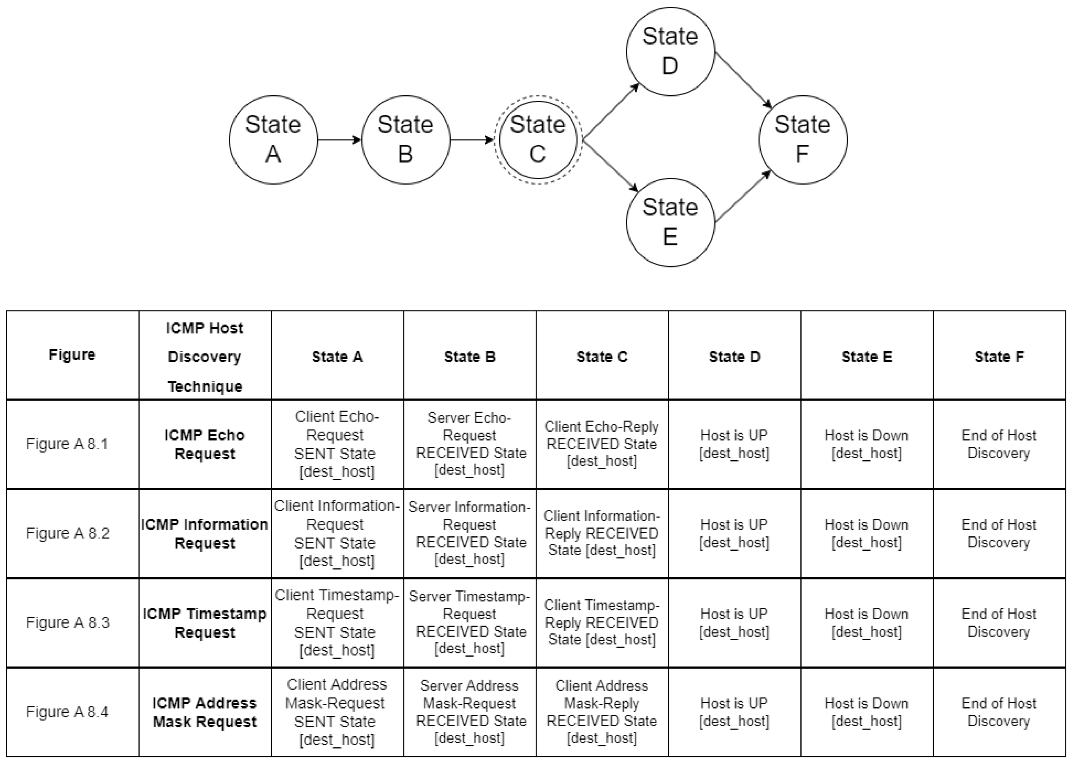
Host discovery reconnaissance is distinguished into three different types, namely ICMP, TCP, and UDP. ICMP or Ping scanning aims to map which hosts are active by sending an ICMP Echo Request (ICMP Type 8) to each host. Hosts that are up and running may respond with an ICMP Echo Reply (ICMP Type 0). However, there are cases of operating systems that by default ignore ICMP echo requests. The ICMP protocol also specifies Timestamp Request (ICMP Type 13), Information Request (ICMP Type 15), and Address Mask Request (ICMP Type 17) packets. While the ostensible purpose for these queries is to learn information such as address masks and current times, they can easily be used for host discovery.
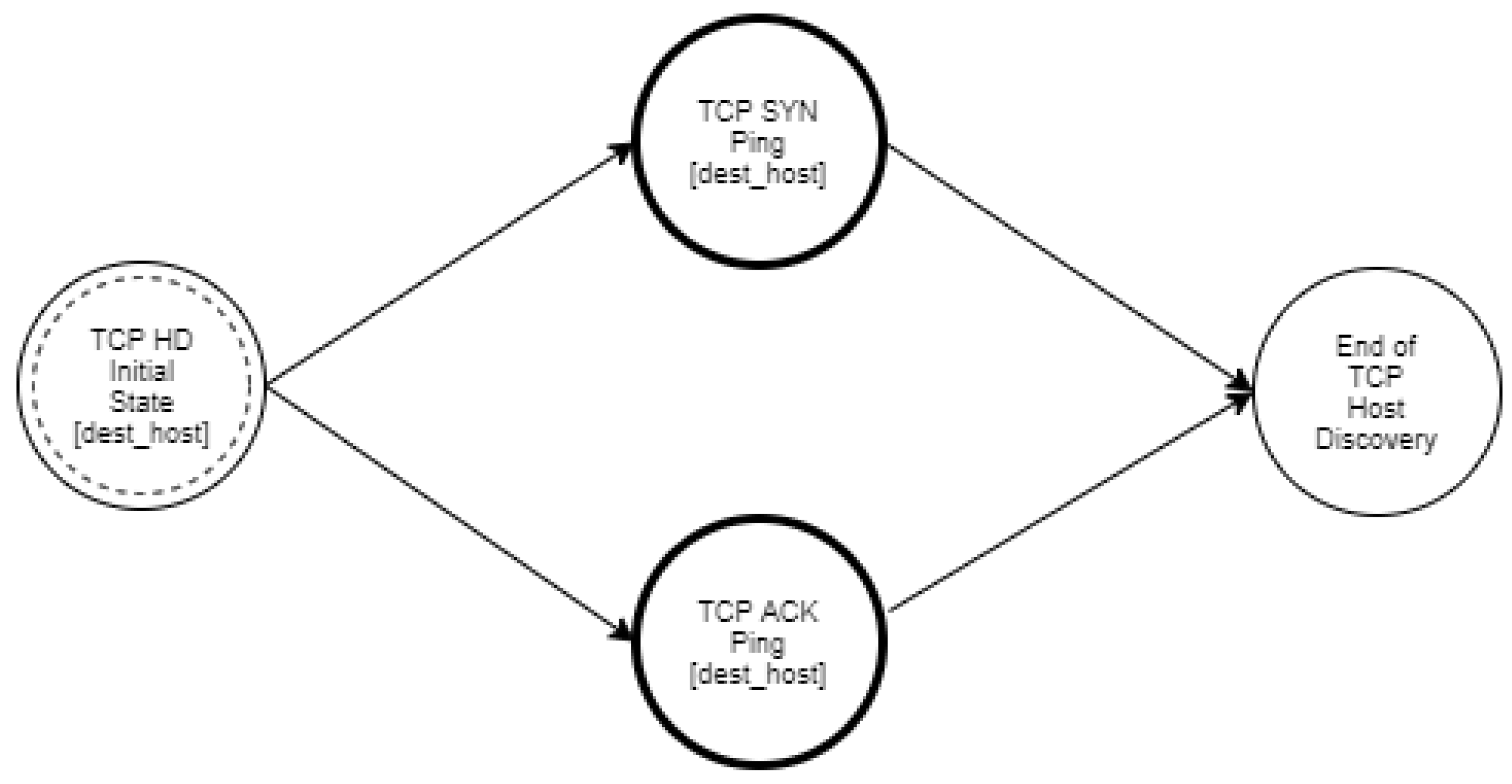
TCP host discovery can be performed by using TCP packets with an SYN or ACK flag set. In both cases, the goal of the intruder is not to conclude whether the port is open or closed, but to detect a RST or SYN/ACK response that reveals whether the host is available and responsive.
Another host discovery option is the UDP ping, which sends a UDP packet to the given ports. On the one hand, if a host is up and available, a closed port should elicit an ICMP Port Unreachable packet in return. On the other hand, for an open port, most services simply ignore the empty packet and fail to return any response. Other types of ICMP errors, such as host/network unreachable or TTL exceeded, are indicative of a host which is down or unreachable.
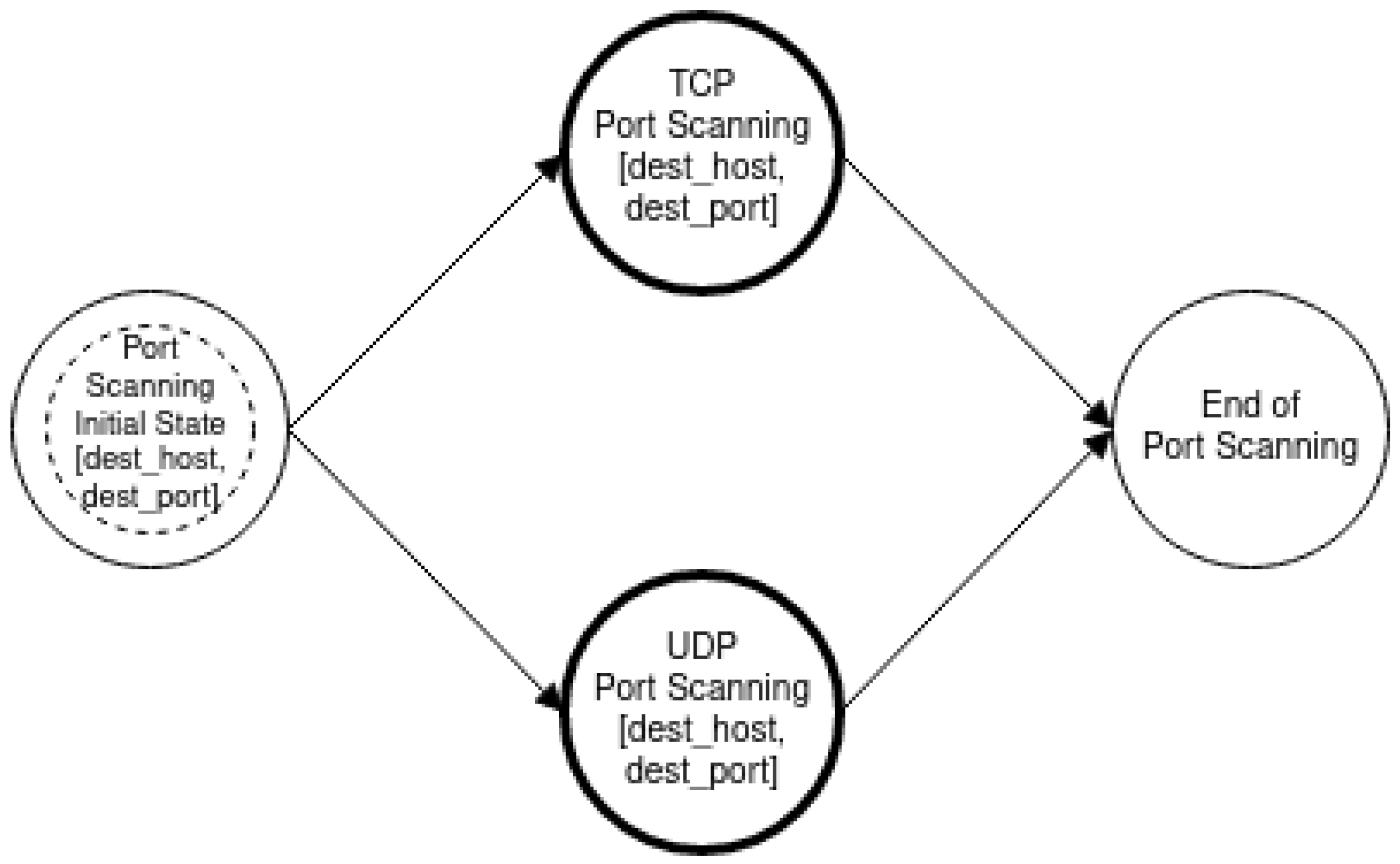
Additionally, there are several techniques for port scanning and they vary depending on the protocol used. The main categories are the following:
- TCP scan: Through this scan, the intruder attempts to find open ports related to the TCP protocol. Scans consisting of probes that attempt the full TCP three-way handshake are called full TCP connection scans. As regards TCP SYN scans or half-open scanning, only the first packet of the TCP three-way handshake, a segment with the TCP SYN flag set, is sent. A TCP Stealth scan is a type of port scanning designed to be undetected by auditing tools. Through this scan, TCP packets are sent to the destination host with stealth flags, such as NULL, FIN, URG, and PSH.
- UDP scan: Through this scan, the intruder attempts to find open ports related to the UDP protocol. However, UDP is a connectionless protocol and can be easily blocked; thus, it is usually not preferred by intruders.
Specifically, for each port scanning method, the following details can be mentioned:
- Full TCP Connection Scans: This type of port scan uses the connect() system call provided by the operating system to connect to a remote host. Specifically, the TCP connect() uses a three-way handshake and will succeed when the port being scanned is listening. When a client wants to connect with a server, it first sends a TCP packet with the SYN flag set. Subsequently, if the port is open, the server sends back a TCP packet with the SYN and ACK flags set and the client computer then sends an ACK packet back to the server. Otherwise, if the port is closed, an RST packet is sent to the client. This method’s advantage is its ease of implementation, as default system calls can be used, while the main disadvantage is that it is easily detectable.
- TCP SYN or half-open scanning: During this type of scan, the port scanning terminates before completing the three-way handshake process. Specifically, only the first stage of the TCP three-way handshake, a segment with the TCP SYN flag set, is sent to the server. If a port is open, the server responds with a TCP SYN/ACK packet. Subsequently, the intruder sends a TCP RST packet, destroying the connection. Such scans are logged less frequently, but non-standard system calls need to be used during execution and special privileges may be required.
- TCP stealth scan: This type of port scan can be performed using an FIN scan, a Null scan or an Xmas tree scan. As regards the FIN scan, the source host sends a packet with just the FIN flag set to the destination host. In the case of a Null scan, a packet is sent with no flags, and in the case of an Xmas tree scan, a packet is sent with a three header flag set (FIN, URG, and PSH). In all three cases, if a port is open, the host ignores the packet and nothing is returned to the intruder. On the other hand, if a port is closed, the host sends back a packet with the RST flag set. The port is filtered if an ICMP unreachable error (type 3, code 0, 1, 2, 3, 9, 10, or 13) is received.
- TCP ACK Scan: During TCP ACK scans, the intruder sends TCP ACK packets to multiple ports on a target and analyzes the TCP RST responses. Responses from open ports may deviate in header values such as TTL and window size on operating systems with BSD-derived TCP/IP stack implementations, while this type of port scanning does not work against hosts with a Windows operating system.
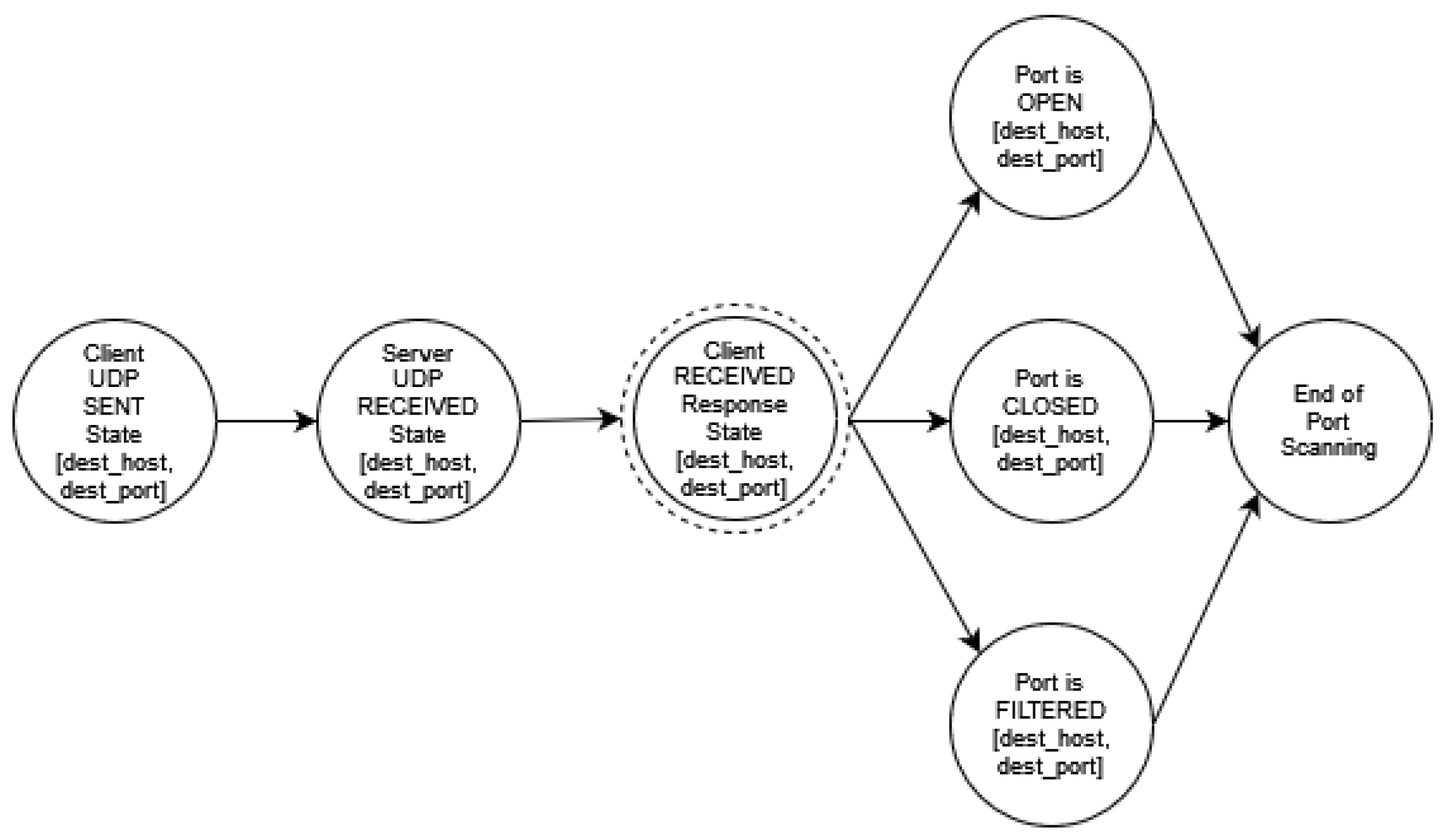
- In UDP port scanning, probing the status of a UDP port is mainly executed by transmitting an empty UDP datagram. If the port is open, it may either respond with an error datagram or ignore the prob. If the target port is closed, an ICMP Port unreachable (Type 3 Code 3) packet should be sent back to the intruder. However, if a datagram is lost or filtered, no response will be received.
4. Modeling Reconnaissance Activity
The present section presents our modeling approach that aims to enable a detailed and extensive representation of intruder activity during the reconnaissance step for a given network. The proposed approach may also take into account partial knowledge/hypotheses about intruder behavior in order to produce a more accurate representation of the steps that they are going to follow. The end result is a set of different paths that the intruder may follow, which is used to calculate metrics with respect to the probability and delay with regard to the event that an intruder may use to conclude a specific piece of information about the network. Such metrics can be useful in the context of defensive deception network techniques.
4.1. State Diagram Analysis Syntax
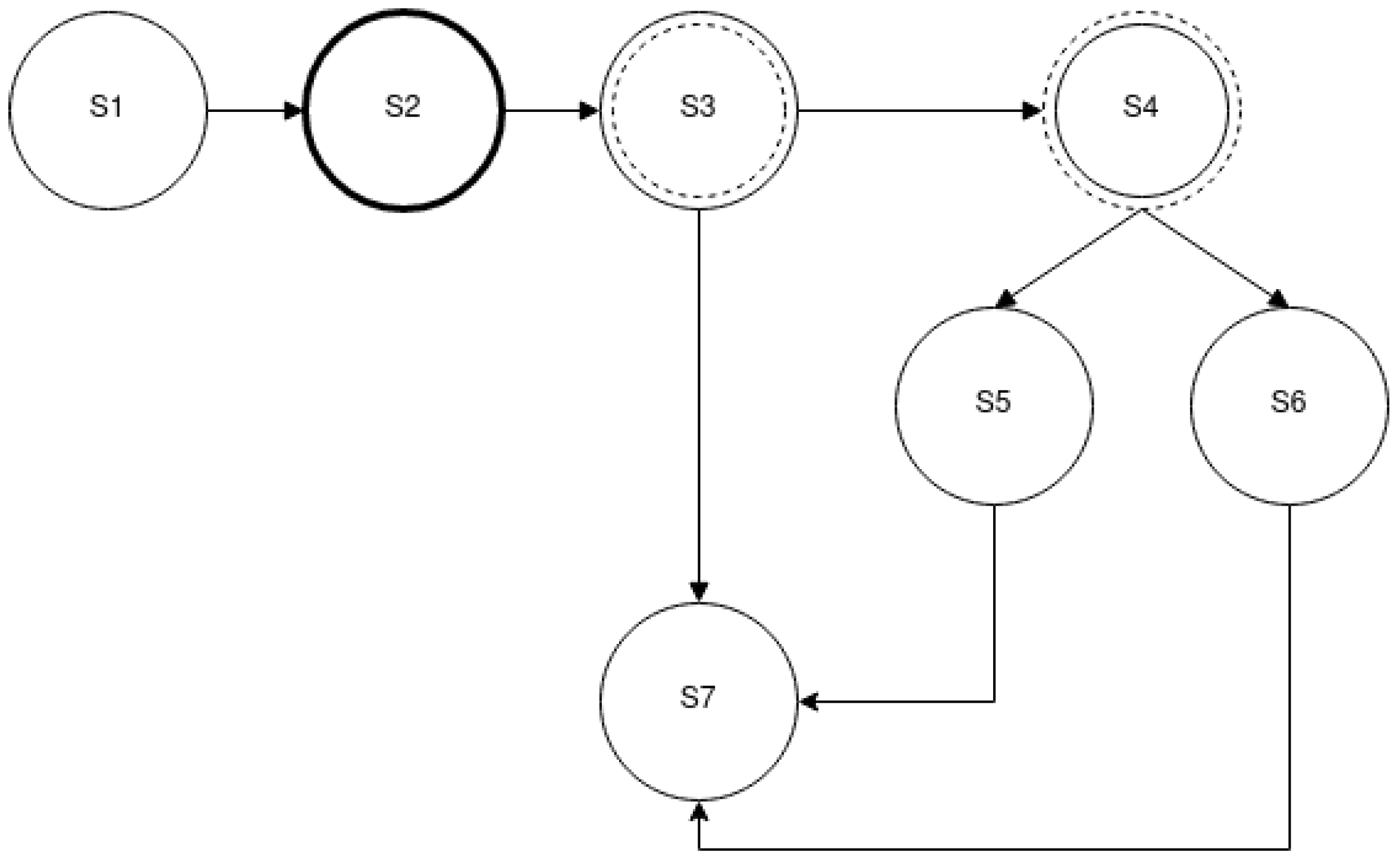
The first building block of our methodology is a hierarchical set of state machines that enables the accurate and efficient representation of an intruder’s actions. Specific syntax is used to model port scanning and host discovery activities as state diagrams. Specifically, the vertices of the state diagram represent the states which an intruder may be in, while the edges represent the transition between those states. States (vertices) are annotated by “S”, while “I” indicates the incoming edges and “O” the outgoing ones.
The set of vertices of the state diagram is denoted as and the set of the edges of the state diagram is denoted as .
Let ∀ s ∈ V, then
where k is the number of incoming edges and m is the number of outdoing edges.
The different types of state diagrams vertices to be used in the host discovery and port scanning analysis are defined in Table 1.
The state diagram starts with an initial state and ends up with one or more final states, while it also includes a number of intermediate states.
The simplest state type is the “Simple” type, which explicitly defines all required detail for the state where the intruder is. There is a more complex state type named “Complex”, which represents the higher complexity functionality and includes another state diagram to model such functionality.
In general, intermediate states have at least one input and one output, while initial states do not have any input, and final states do not have any outputs.
There are two special sub-types for ”Simple“ states that serve the case when a state may have more than one output and according to specific parameters may lead to different subsequent states. Both can have more than one output. For Intruder-decision-driven states, the next state is decided according to the intruder’s choice with regards to reconnaissance methodology, while for Network-input-driven states, the next state is decided upon the results of a scanning action on a specific network.
In addition, each of the state diagram vertices may contain optional variables that provide details about the context in which each state takes place. For example, if a state represents host discovery activity, then it shall also include a variable holding the destination IP address, to which the host discovery is targeted. If this state is a “Complex“ state, then it inherits this variable in the state diagram that further analyses the host discovery behavior.
- State S1 in Figure 1 is a “Simple“ state and acts as the initial state of the state diagram.
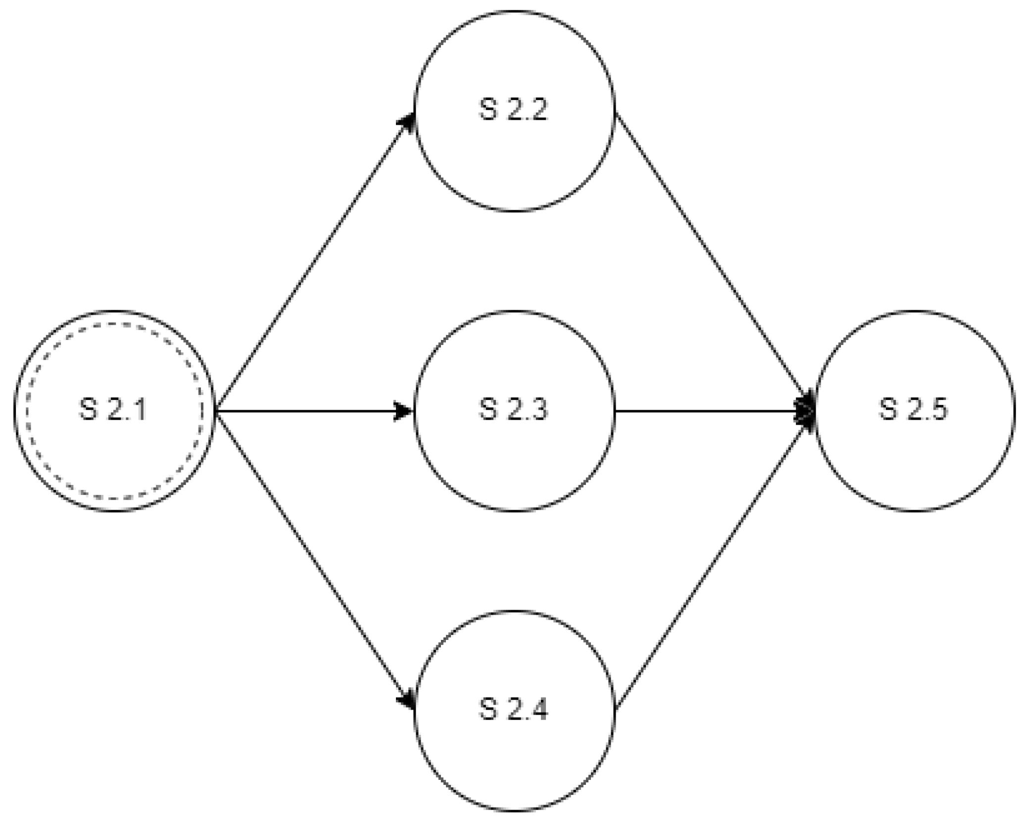
- State S2 is a “Complex“ state and the reconnaissance activity carried out during this state is further analyzed in another state diagram shown in Figure 2. What actually happens is that the intruder transits from state S1 in Figure 1 to state S2.1 of Figure 2. When the activity in Figure 2 is concluded, the intruder transits from state S2.5 of Figure 2 to state S3 of Figure 1.
- State S3 is an “Intruder-Decision-driven“ state. The next state is decided upon the behavior of the intruder. The next state is going to be either S4 or S7 according to which methodology is preferable to the intruder. During the analysis of the expected reconnaissance activity, complete knowledge of the intruder’s preferred methodology will enable the extraction of a single path, while incomplete knowledge will produce a pair of paths, one of which will categorize and represent that the next step is based on the intruder’s assessment.
- State S4 is a “Network-input-driven“ state and represents a state in which the next transition is dependent upon the input that the intruder receives from the network. As the protected network’s structure is always known during the analysis of the expected reconnaissance activity, the result is a single path, either the one transitioning from S4 to S5 or the one transitioning from S4 to S6.
- States S5 and S6 are “Simple“ states that sufficiently describe the activity of the intruder and have a single transition option when those are finalized.
- State S7 is a “Simple“ state that also happens to be the final state of the state diagram and thus does not have any outgoing edges.
4.2. Reconnaissance Activity Representation
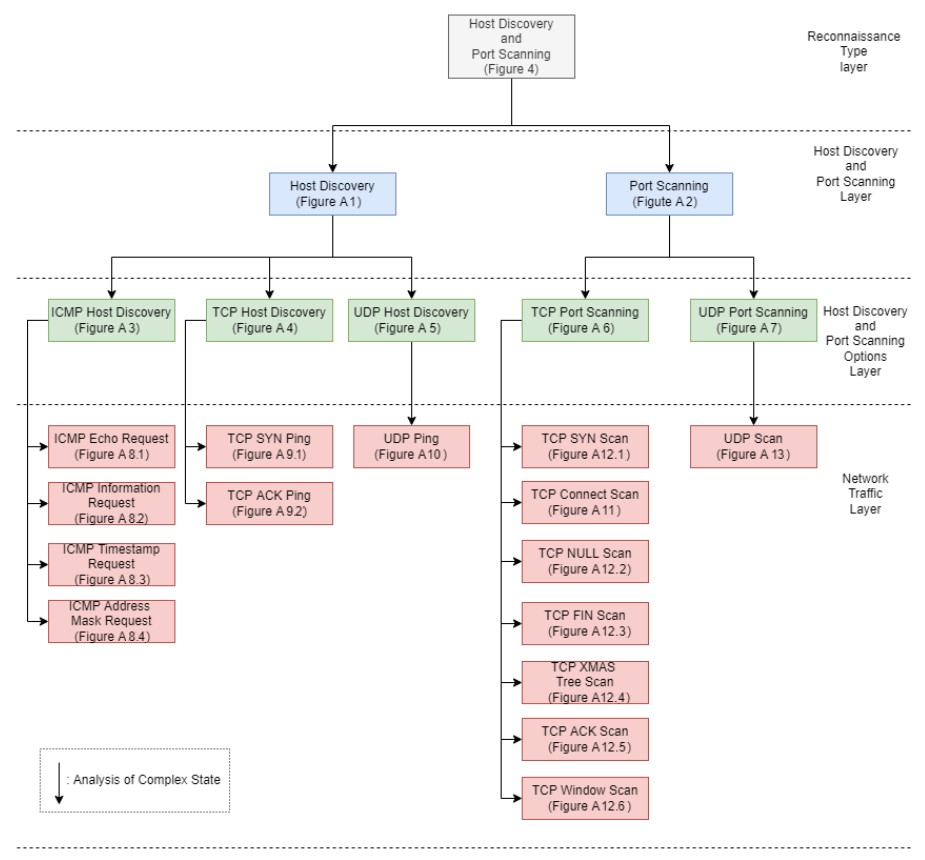
As mentioned in Section 3, the goal of an intruder during the reconnaissance phase of an attack is to identify the hosts of a network and to detect the open ports of each host. The proposed approach aims at modeling such activities of the intruder in order to enable the accurate detection of such events and to facilitate the optimal operation of deception mechanisms. Specifically, we used a multilayered approach that defines different state diagrams at different detail layers, as depicted in Figure 3. The activity represented by a state diagram in a layer can be further analyzed by a state diagram in a lower layer. Specifically, the state diagram of the “Reconnaissance Type” layer can be analyzed in two state diagrams in the “Host Discovery and Port Scanning” layer. Furthermore, these state diagrams can be analyzed further in “ICMP Host Discovery”, “TCP Host Discovery”, “UDP Host Discovery” and “TCP Port Scanning”, “UDP Port Scanning”, respectively, and constitute the state diagrams of the “Host Discovery and Port Scanning Options“ layer. Finally, in the “Network Traffic“ layer, the “ICMP Host Discovery” is analyzed in “ICMP Echo Request”, “ICMP Information Request”, “ICMP Timestamp Request” and “ICMP Address Mask request”, “TCP Host Discovery” is broken down into “TCP SYN Ping” and “TCP ACK Ping”. “UDP Host Discovery” is analyzed in “UDP Ping”. As regards “TCP Port Scanning”, it is analyzed in “TCP SYN Scan”, “TCP Connect Scan”, “TCP NULL Scan”, “TCP FIN Scan”, “TCP Xmas Tree Scan”, “TCP ACK Scan”, and “TCP Window Scan”. Regarding “UDP Port Scanning”, it is analyzed in “UDP Scan“.
4.2.1. Reconnaissance-Type Layer
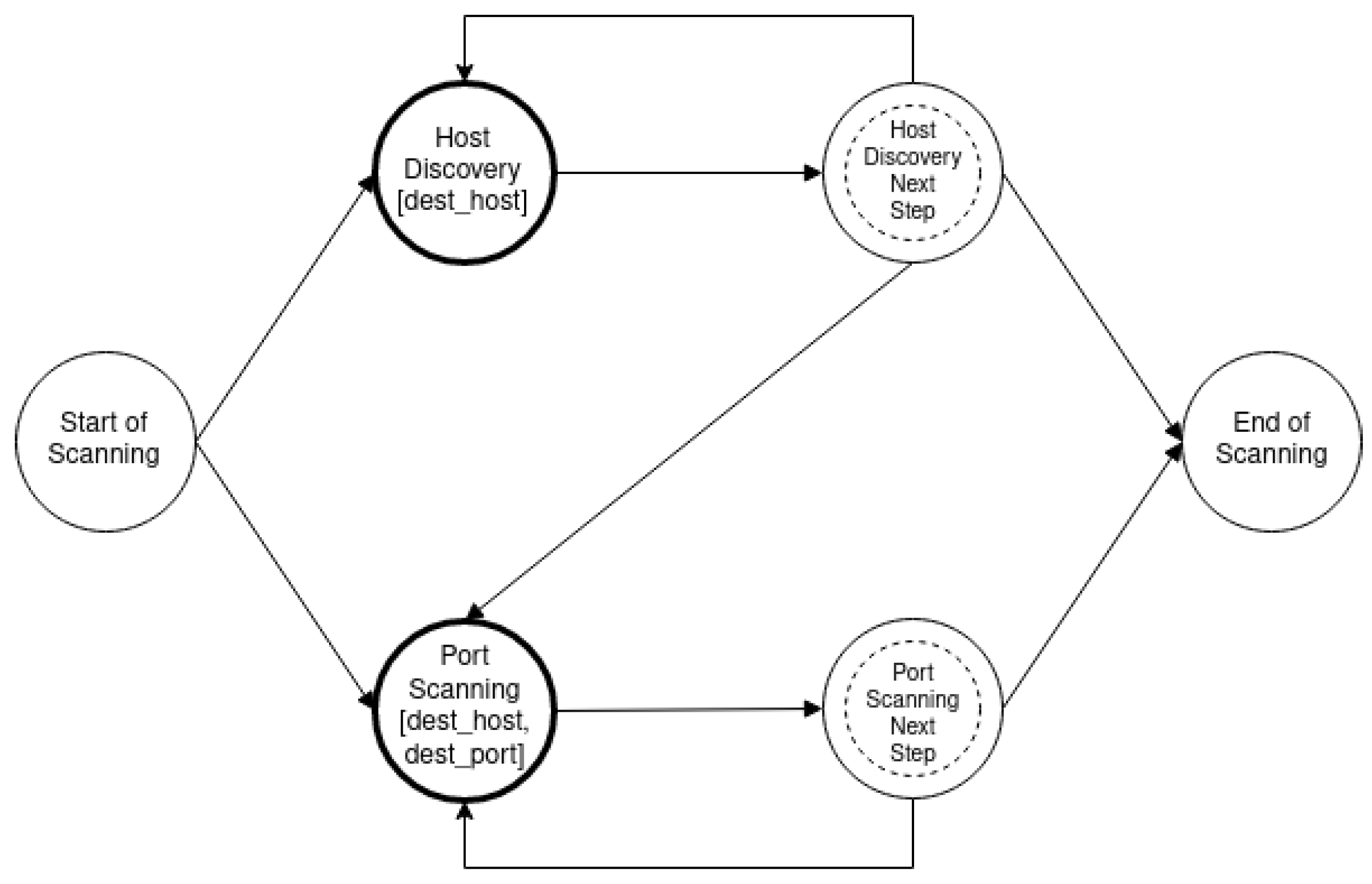
The first layer contains a single-state diagram, which gives a high-level representation of all reconnaissance activities. The state diagram of this layer describes the intruder’s decision regarding the order with which they will proceed with host discovery or port scanning reconnaissance and those options form the state diagram’s nodes. Each node of the state diagram belongs to the complex state category and the edges represent the intruder’s decision based on the strategy followed.
The host discovery and port scanning state diagram is depicted in Figure 4 and describes an approach where the intruder horizontally scans all addresses to identify the alive hosts and then continues by scanning the ports of each detected host. The rest of the state diagrams are listed in Appendix A.
4.2.2. Host Discovery and Port Scanning Protocol Layer
The state diagrams of this layer represent the activity through which the intruder goes through the host discovery and port scanning workflow for a host or a port, respectively. The two-state diagrams of the layer analyze in more detail the complex states of the state diagram in Figure 4 and correspond to the selection of the protocol to be used for host discovery or port scanning reconnaissance by the attacker. The state diagrams consist of complex nodes that correspond to available protocols. Additionally, the edges represent the intruder’s decision based on the strategy followed.
4.2.3. Host Discovery and Port Scanning Protocol Options
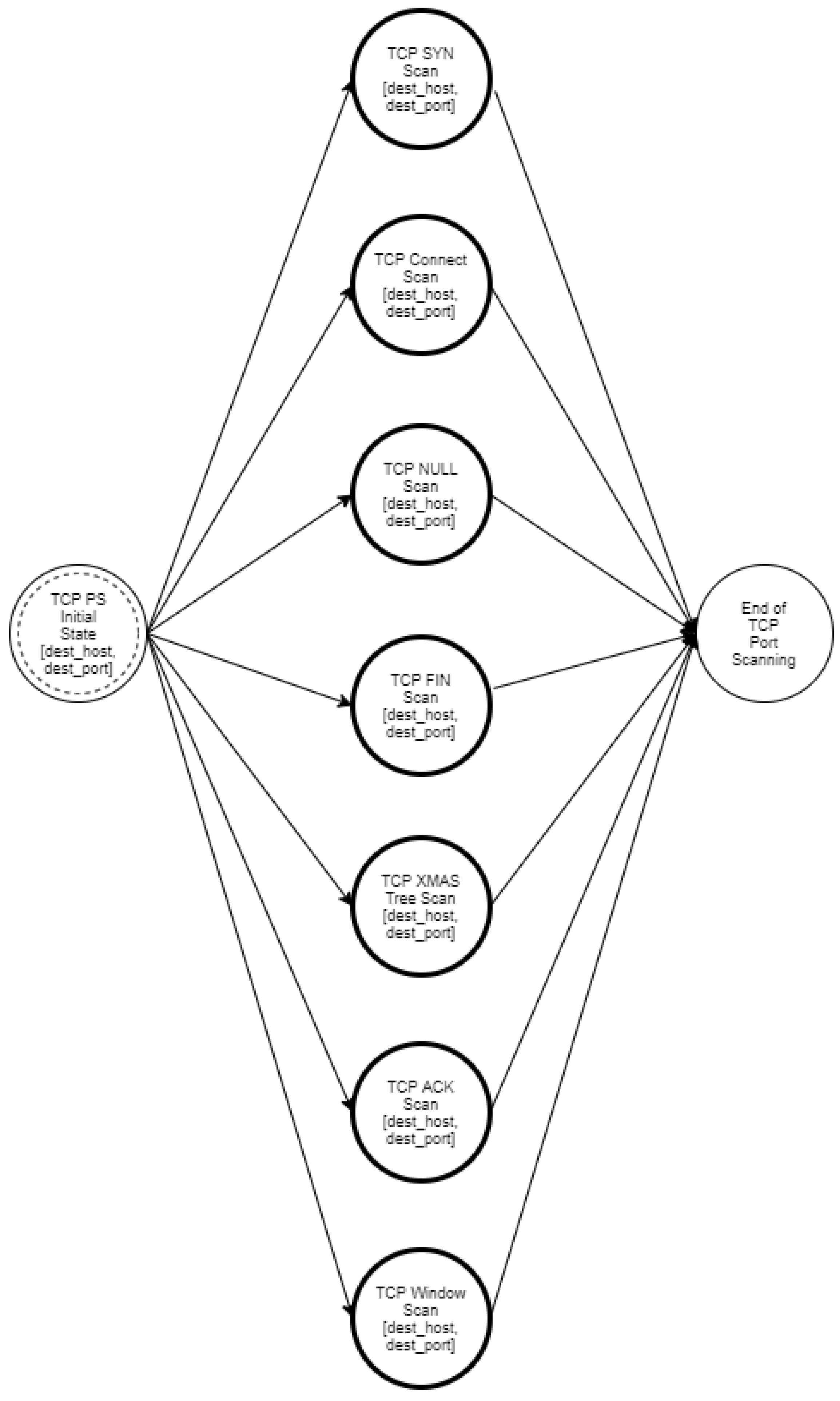
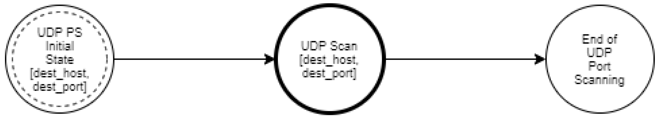
In the state diagrams of this layer, a detailed analysis of the available techniques is performed based on each protocol. The state diagram nodes consist of the available options per protocol. Specifically, Figure A3, Figure A4 and Figure A5 are the state diagrams for ICMP, TCP, and UDP host discovery, respectively. Similarly, Figure A6 and Figure A7 are the state diagrams for port scanning.
4.2.4. Network Traffic
In state diagrams of this layer, the intruder has made their choice based on the strategy followed and commits to the scanning by sending network traffic to the target.
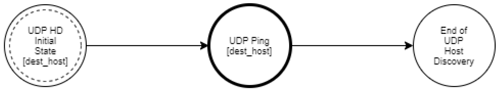
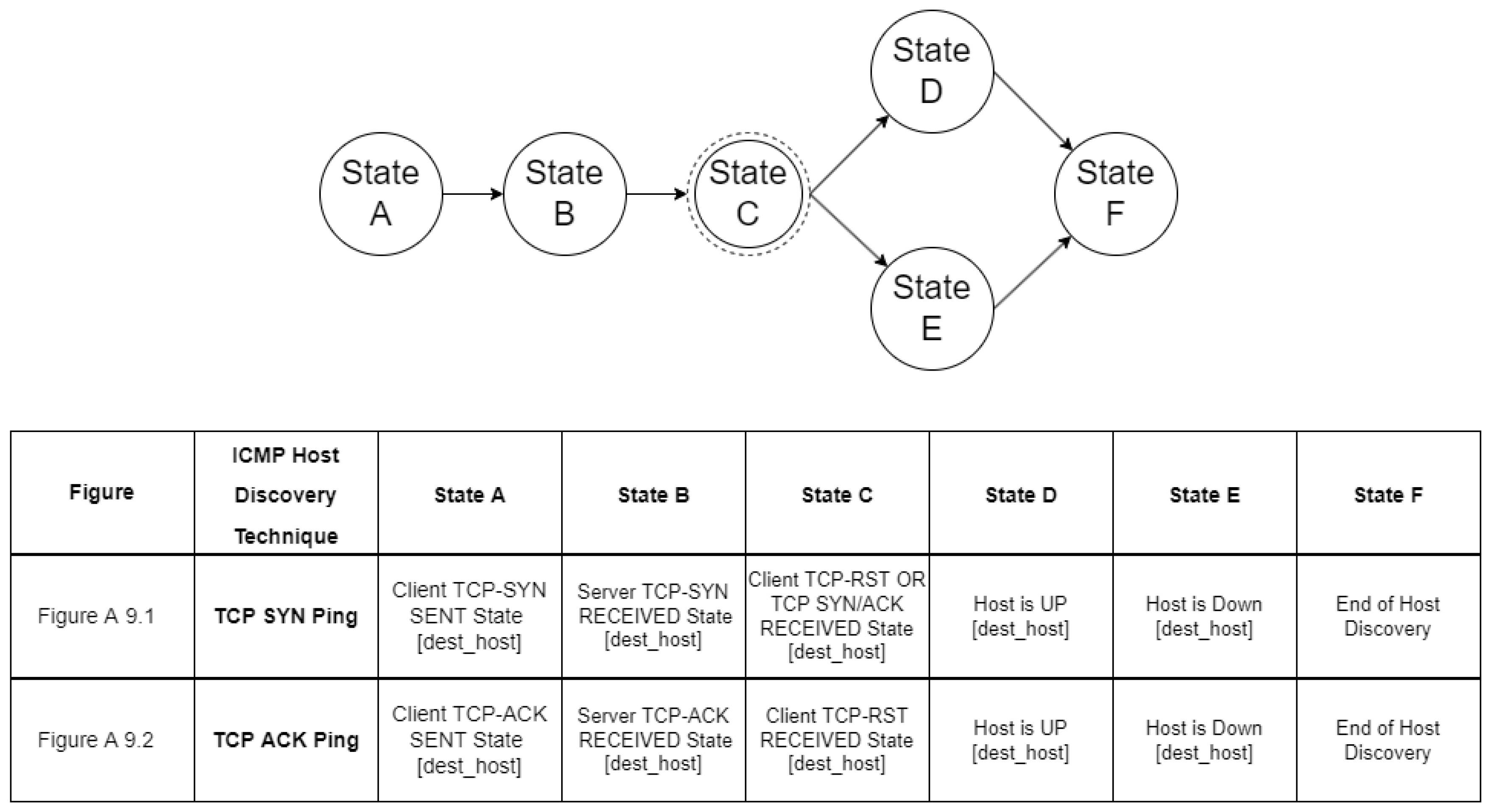
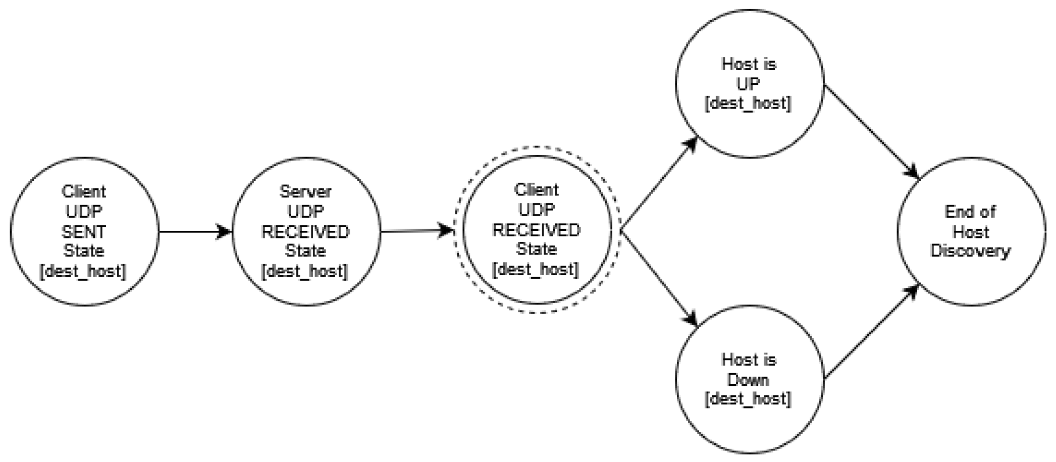
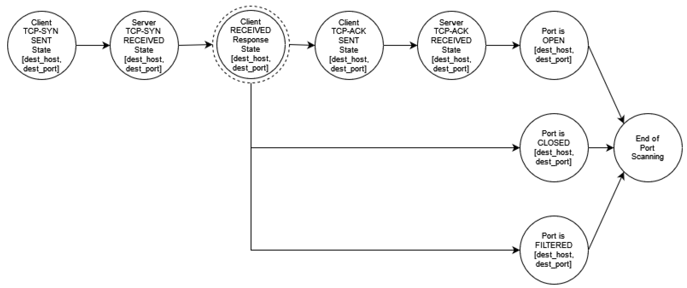
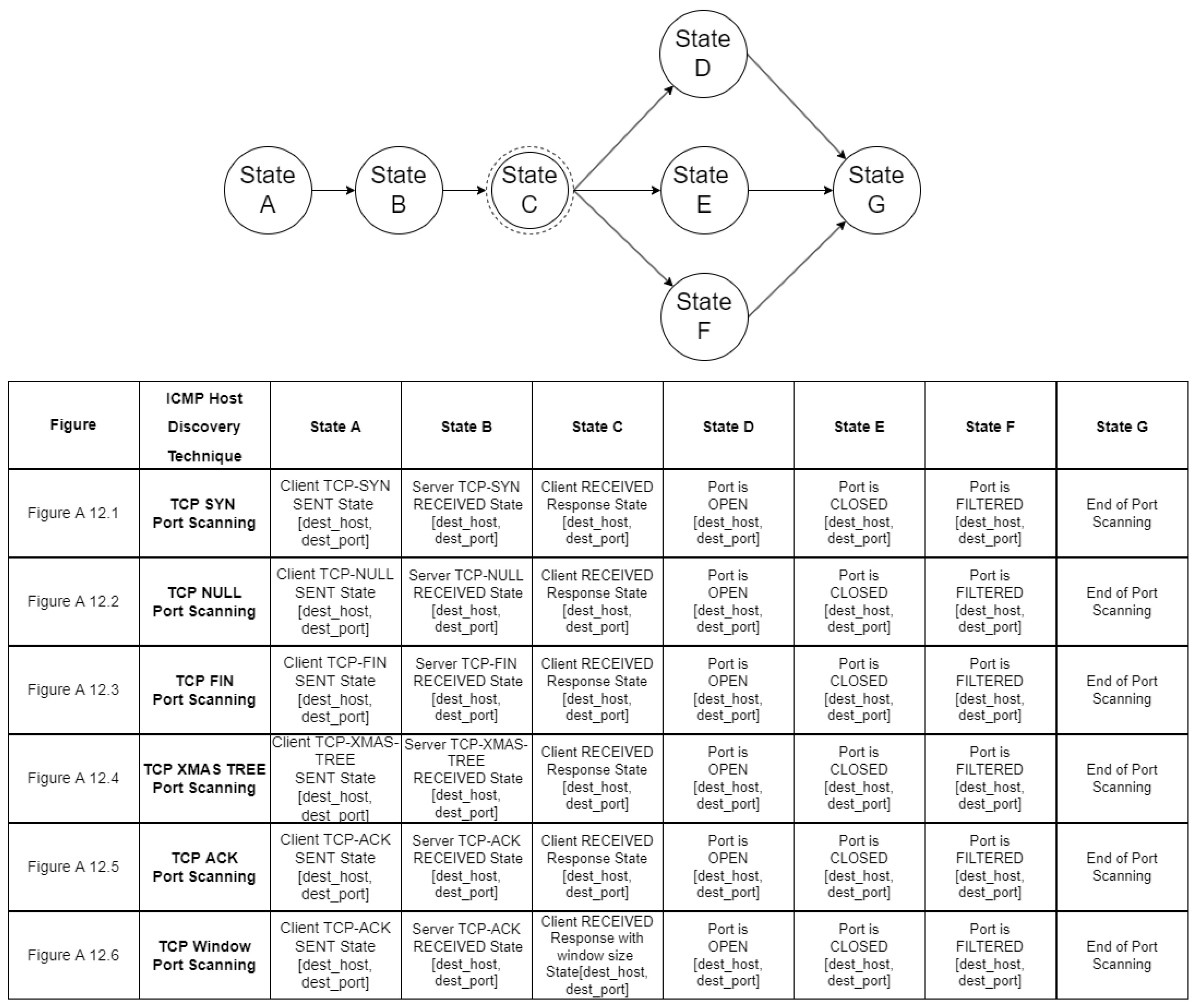
For example, Figure A8 represents the communication between an intruder and a target in the case of an ICMP host discovery. The state diagrams of this layer do not include any additional complex states as this is the lowest layer of our modeling scheme. Similarly, Figure A9 and Figure A10 show the network traffic for host discovery and Figure A11, Figure A12 and Figure A13 show the network traffic for port scanning.
4.3. Modeling Intruder’s Behavior
An important parameter for the modeling of reconnaissance activity is the intruder’s decisions in different steps of the process. In this subsection, a scheme to model the decisions of an intruder with respect to reconnaissance activities, such as host discovery and port scanning in a network, is described. As mentioned in Section 3, regarding host discovery, the different options of the intruder are (i) ICMP Echo Request, (ii) ICMP Timestamp Request, (iii) ICMP Information Request, (iv) ICMP Address Mask Request, (v) TCP SYN Ping, (vi) TCP ACK Ping, and (vii) UDP Ping. Regarding port scanning, the different options are (i) TCP SYN Scan, (ii) TCP Connect Scan, (iii) TCP NULL Scan, (iv) TCP FIN Scan, (v) TCP XMAS Tree Scan, (vi) TCP ACK Scan, (vii) TCP Window Scan, and (viii) UDP Scan.
Therefore, all possible actions/decisions of an intruder can be represented as elements of two distinct sets.
and
The behavior of an intruder i is represented by a tuple of subsets of the sets HD and PS.
where includes all host discovery techniques that intruder i uses, while includes all port scanning techniques that intruder i uses.
An example of a representation of the knowledge about the behavior B of a specific intruder is shown in the following:
B = {
{
{
ICMP Echo Request,
ICMP Information Request
}
},
{
{
TCP SYN Scan
}
}
}
For the specific intruder, there is no complete knowledge about their preferences regarding host discovery but it is known that he uses either ICMP Echo Request or ICMP Information Request. Regarding port scanning, it is explicitly known that they are using a TCP SYN Scan. As a result of the incomplete knowledge of the host discovery approach of the intruder, it is expected that during the analysis of the state diagrams, more than one probable path to be followed by the intruder will be extracted.
4.4. Modeling Network Topology
The other parameter that greatly influences the reconnaissance activity of an intruder is the protected network’s structure and the knowledge that the intruder gains on it during reconnaissance. A syntax to describe the structure of the network on which an intruder performs reconnaissance activity is defined in the present subsection. The model describes the hosts that are up and running, as well as the ports (services) that are open for each host.
The representation of the network topology including one element for each host of the network is
Each one of these elements describes the IP address of the host and two sets of open ports (tcp and udp).
where
An example of modeling a network topology is given in the following:
NT = {
{
192.168.0.1:
[22, 80, 443],
[69]
},
{
192.168.0.5:
[22],
[]
}
}
This network comprises two hosts. The first one is 192.168.0.1 with three tcp ports open (22, 80, 443) and one udp port open (69), and the second one is 192.168.0.5, for which the only open port is TCP/22.
4.5. Modeling Firewall Setup
Complementary to the modeling of the network topology, there is a need for modeling the firewall topology in a network since it is not possible to allow all incoming connections to the internal network. The representation of the firewall topology including one element for each host of the network is
Each one of these elements describes the IP address of the host, two sets of allowed ports (tcp and udp), and one entry if icmp host discovery is permitted or not. It should be mentioned that for modeling we use the three main protocols (tcp, udp, and icmp) for the reconnaissance activity.
where
An example of modeling a firewall topology is given in the following:
FS = {
192.168.0.1: {
[80, 443],
[69],
“True“
},
192.168.0.5: {
[22],
[],
“False“
}
}
4.6. Metrics
Modelling the reconnaissance activity and extracting the number of probable paths in the described state diagrams that represent the expected activity of the intruder enables us to better assess the consequences (the knowledge intruder gains with regard to a specific node in the protected system). The intruder’s reconnaissance activity in the network is modeled using state diagrams. Using state diagrams has the advantage that through the use of graph theory it is feasible to locate nodes and neighbors on the state diagram and to process paths between nodes.
In this subsection, we define a number of metrics that are easily calculated and enable the network administrator to better understand the effects of the reconnaissance of the network. The same metrics can be eventually used to compare different protection approaches, such as deception techniques.
After analyzing the intruder’s activity, we end up with a number of probable behavior paths that the intruder may follow (mainly due to our incomplete knowledge of the intruder’s preference of technique). Let us assume that the set of extracted paths is .
Let us assume a specific node n, which is an actual instance of one of the nodes of the state diagrams described in Section 4.2 (a node with set optional variables, e.g., ip or port). The occurrence of this node in a path means that the relevant action (e.g., scanning a specific port of a host) has been executed by the intruder.
The basic metrics calculated are described in the following subsections.
4.6.1. Node Occurrence
The occurrence, , of a node n is a binary metric that represents if node n is present in any of the extracted paths.
4.6.2. Node Occurrence Probability
The probability of occurrence of a node shows how likely it is for a node to exist in the path the intruder will follow.
Given a specific network topology and an incomplete level of knowledge of the intruder’s behavior, we end up with a set of multiple paths, one of which is the path the intruder will follow. As there are more than one probable paths that the intruder may follow, the probability of having a specific node in the valid path that will be instantiated is equal to the portion of paths that include the specific node.
For a given path we calculate a weighted probability regarding the occurrence of node n in it. This is equal to zero if node n does not exist in the path. For paths that include the node, the weighted probability is inversely proportional to the distance from the start of the path to the position of the node.
The total node occurrence probability is the average weighted probability for the node along all paths.
If a node is present in multiple paths (preferably early along those paths) it has a higher occurrence probability.
4.6.3. Average Hops to a Node
Another important metric that enables the development of more efficient deception approaches is related to the time/effort required for an intruder to obtain a specific piece of information. This can be approximated through our analysis by counting the number of nodes that precede the node (related to the specific piece of information) in all probable paths and calculating the average value between paths.
where
The metric represents the expected delay for an intruder to reach a specific point of the reconnaissance process, given a specific network topology and a specific level of knowledge of the intruder’s behavior.
In the case of full knowledge of the intruder’s behavior, in which the analysis will produce a single path, then the metric represents the actual path length to node n on the extracted path.
4.6.4. Average Hops between Nodes
A similar metric is the average number of hops between two nodes. This represents the time/effort required for an intruder to reach a specific point (node) after he has gone through another point. For example, this could be related to the effort required between learning that a specific host is alive and that a specific port of the host is open.
The calculation is similar to the average hops to a node metric.
where
4.6.5. Metrics Calculation Example
In the present subsection, we will present a calculation of the above metrics for a given network topology with and without deception measures applied. The initial calculation is performed for a network topology that consists of 15 Workstations, 2 Web servers, 2 Database servers, and 1 File Server. Next, we present a calculation of the metrics for the same network topology given that 20 deception hosts have been added to the network. In both cases, the node for which the metrics are calculated is the File server since it is considered the most critical node of the network.
The calculation of the metrics aims at showcasing their usability with respect to quantifying the overhead induced to the attacker by using a given defensive deception mechanism.
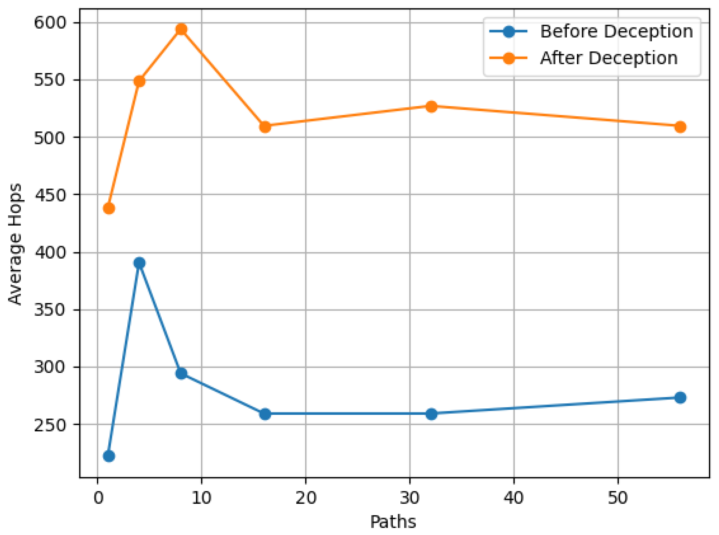
Figure 5 shows the “Average hops to a node” metric. Specifically, the requested node is “port 445 of the File server is Open” using TCP SYN Scan. As shown, the average hops to reach this node is lower in the initial network topology than in the deception network topology.
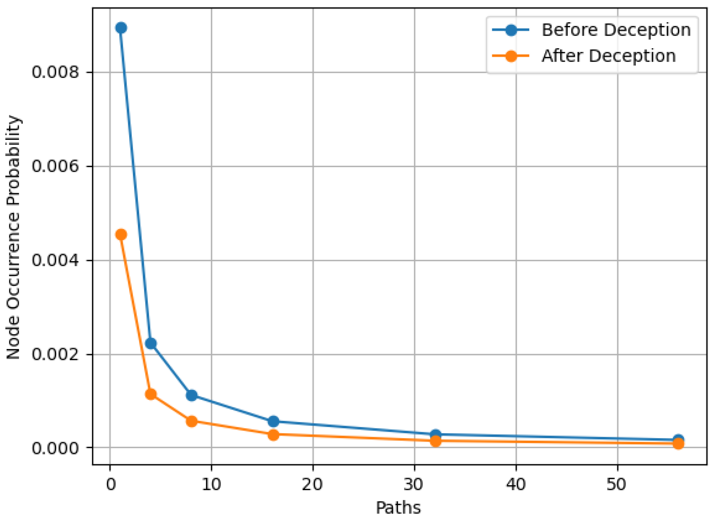
Figure 6 shows the “Node Occurrence Probability” metric. Specifically, the requested node is “port 445 of the File server is Open“ using TCP SYN Scan. As shown, the occurrence probability of this node is lower in the deception network topology than in the network topology before the deception.
In the specific scenario, we assume a number of different knowledge levels for the intruder’s behavior which leads to varying numbers of paths. For each one of these scenarios, we take into account a specific deception strategy (adding 20 deception hosts) and we calculate the proposed metrics before and after applying the defensive deception mechanism.
The results for the metrics (Node occurrence probability and the Average hops to a node) of the node that represent the event “port 445 of the File server is found Open using TCP SYN scan” are given in Figure 5 and Figure 6.
For the “Average hops between nodes“ metric, the distance between the node “File Server is UP“ using ICMP Echo Request and “port 445 of the File server is Open“ using TCP SYN Scan is calculated. This corresponds to the time required for the intruder to determine the existence of a service on the host after the discovery of the host itself. This is independent of the number of paths. Initially, this distance is 121 hops and after the use of the deception mechanism, this distance is increased to 237 hops.
In general, it has to be noted that in scenarios with a high level of knowledge of the intruder’s behavior (and thus a low number of total paths), the effect of the occurrence of a single node (corresponding to a single action) in a path is stronger with respect to the aforementioned metrics. On the other hand, when the level of knowledge is lower, the effect of the occurrence of a node is less evident. As the number of paths increases in Figure 5 and Figure 6, the values of the metrics tend to be less affected by the occurrence of a node in a single path.
5. Implementation
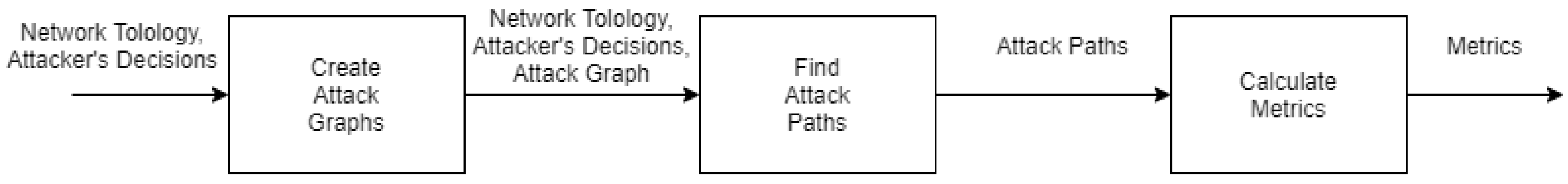
In this section, an implementation based upon the analysis scheme presented in Section 4 is presented. We consider the scheme that defines how the processes of host discovery, port scanning, intruder behavior, network topology, and firewall setup are modeled. A software system that detects a computer network intruder, as well as the prediction of its next move, has been implemented. The implementation consists of the following components: (a) attack graph extractor, (b) path extractor, and (c) metric calculator. The components of the system are shown in Figure 7.
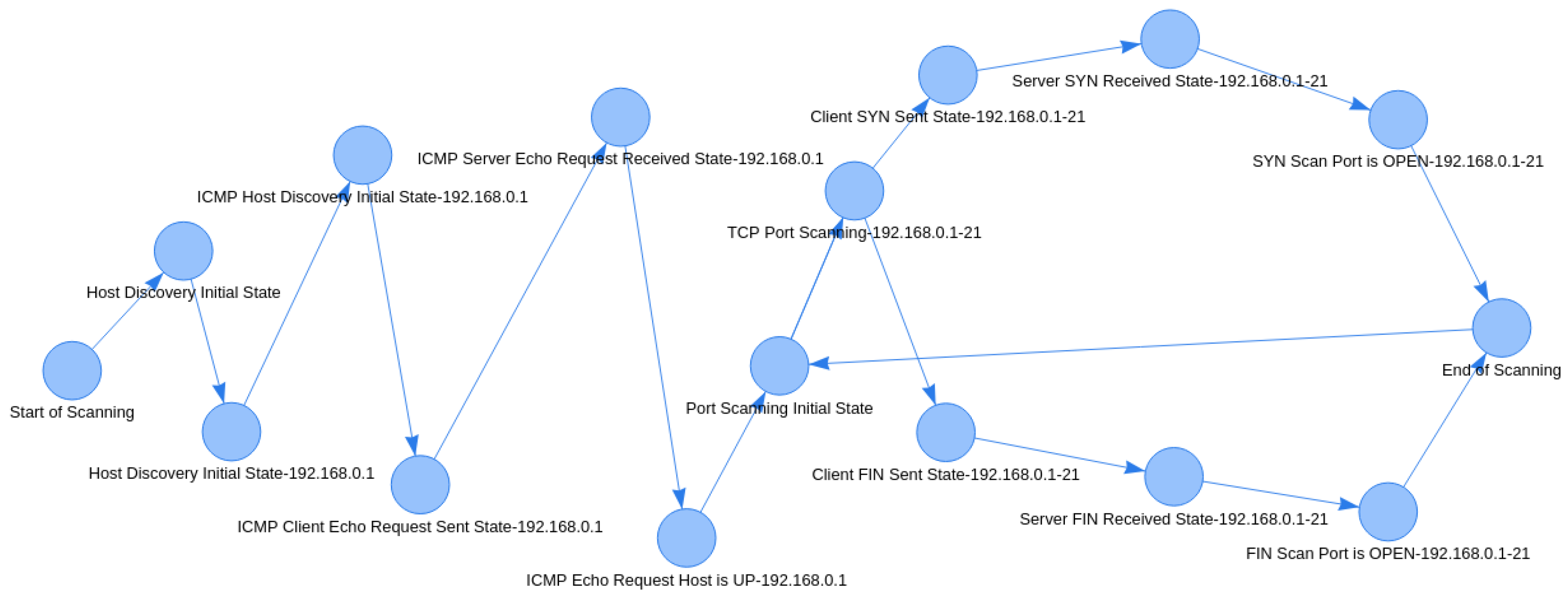
The attack graph extractor component receives the network topology, the firewall setup, and intruder’s decisions as inputs and creates an attack graph as output. In order to create an attack graph, state diagrams from all layers are combined into a large diagram. For example, if an intruder chooses to perform host discovery using an ICMP Echo Request, then the Echo Request state diagram will be integrated into the main diagram. Similarly, in the case of port scanning, if the intruder performs a TCP Port Scan, then the TCP Port Scan state diagram will be added to the main diagram. All of the above are repeated for every single port of all computers in the network topology. An example of an attack graph is shown in Figure 8.
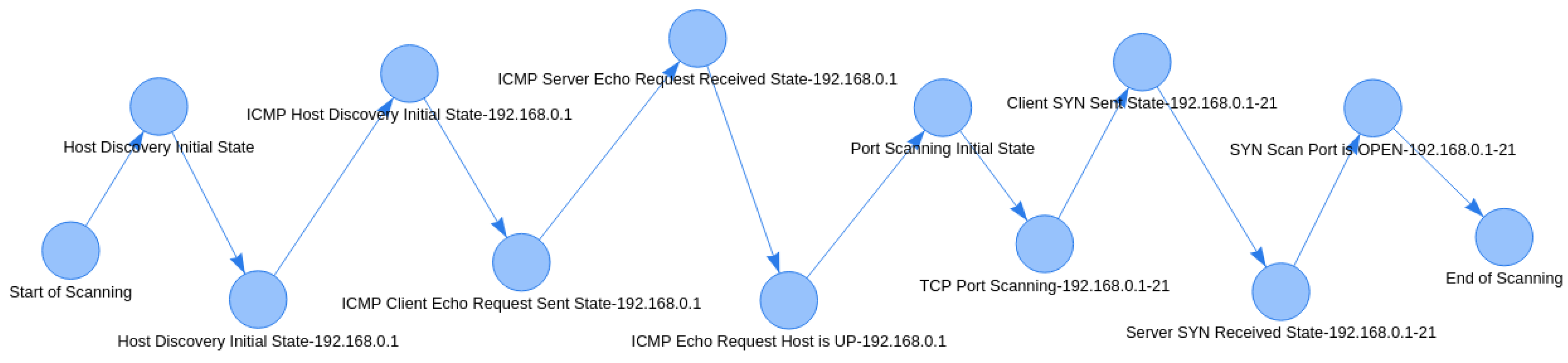
The path extractor component takes the attack graph from the previous step, the network topology, and the intruder’s decisions as inputs and outputs all probable attack paths. Each intruder decision will create a new path. For instance, if an intruder opts for ICMP Echo Request for host discovery and TCP SYN Scan or TCP FIN Scan for port scanning, then two probable paths are created. The number of extracted paths is equal to the number of different combinations between all open options for the intruder with regard to host discovery and port scanning.
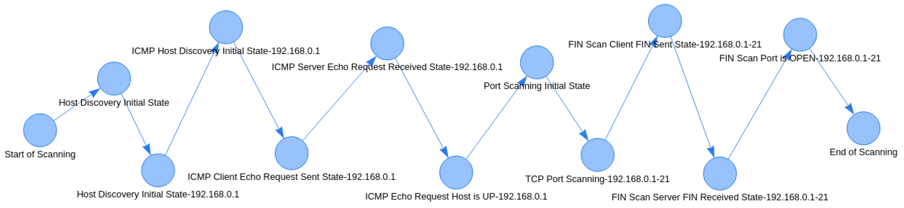
In our example, the number of paths is two (one host discovery method * two port scanning methods); the first path corresponds to the case in which a TCP SYN Scan is used for each port, while the second corresponds to the case in which a TCP FIN Scan is used. The two distinct attack paths extracted for the example analysis in Figure 8 are shown in Figure 9 and Figure 10.
The metric calculator component calculates metrics from the generated attack paths. Given that the path extractor component has produced the probable attack paths for a specific network topology and a specific level of knowledge of the intruder’s behavior, the metric calculator component can efficiently calculate the metrics defined in Section 4.6 for any node. The metric calculator is of high significance, as it enables instantly assessing the risk with respect to a specific asset in the network when an intruder is detected. The results obtained from the metric calculator component can be used to enable fast and efficient decisions with regard to applying deception measures. On top of this, the same results can also be used to better understand the increase in the level of protection that such measures lead to, as it quantifies the difficulty of an intruder obtaining a specific piece of information.
6. Experiments
In the previous sections, we presented the processes of creating attack graphs, creating attack paths, and calculating metrics. It is important to execute these processes as fast as possible, as the information produced can enable the mitigation of the attack in real time. To find out how fast the mechanism described in Section 5 produces its results, we performed a series of experiments. The main goal of the experiments was to understand the hardware requirements with respect to the parameters of the experiment (such as the network size or knowledge of the intruder’s behavior) in order to produce the aforementioned results with a bearable time overhead. As the main hardware resource that may limit performance is processing, we opted for using a host with an Intel® Xeon® Silver 4210 Processor and measured the dedicated CPU resources through the number of threads used in each scenario.
The parameters of the experiments were:
- The number of CPU threads;
- The size of the network;
- The level of knowledge of the intruder’s decisions.
In order to quantify the network size with respect to reconnaissance effort, the number of distinct actions an intruder has to go through is calculated by Equation (18).
where is the number of hosts in the network, while is the average number of open ports on these hosts. The metric is used to describe the size of the network in the experiments presented in the rest of this section.
In regard to the level of knowledge of the intruder’s decisions, the number of combinations of open intruder’s preferences for host discovery and port scanning is used as a metric. If, for example, there are three techniques for host discovery and four techniques for port scanning, then twelve different combinations are possible and thus twelve attack paths are expected as output. The experiments were performed for a series of different values for the parameters described. These values are listed in Table 2.
A total of 750 experiments were performed for the above cases. In this section, we present the time required to complete the described steps.
Specifically, we present the time required for the initial process carried out by the first two components (the attack graph extractor and the path extractor), which has to be completed once per combination of network topology and knowledge of the intruder’s behavior.
On top of that, we also present the time required for the calculation of metrics for a random node input by the metric extractor component. This is a process that may be required to be completed multiple times after completing the initial process.
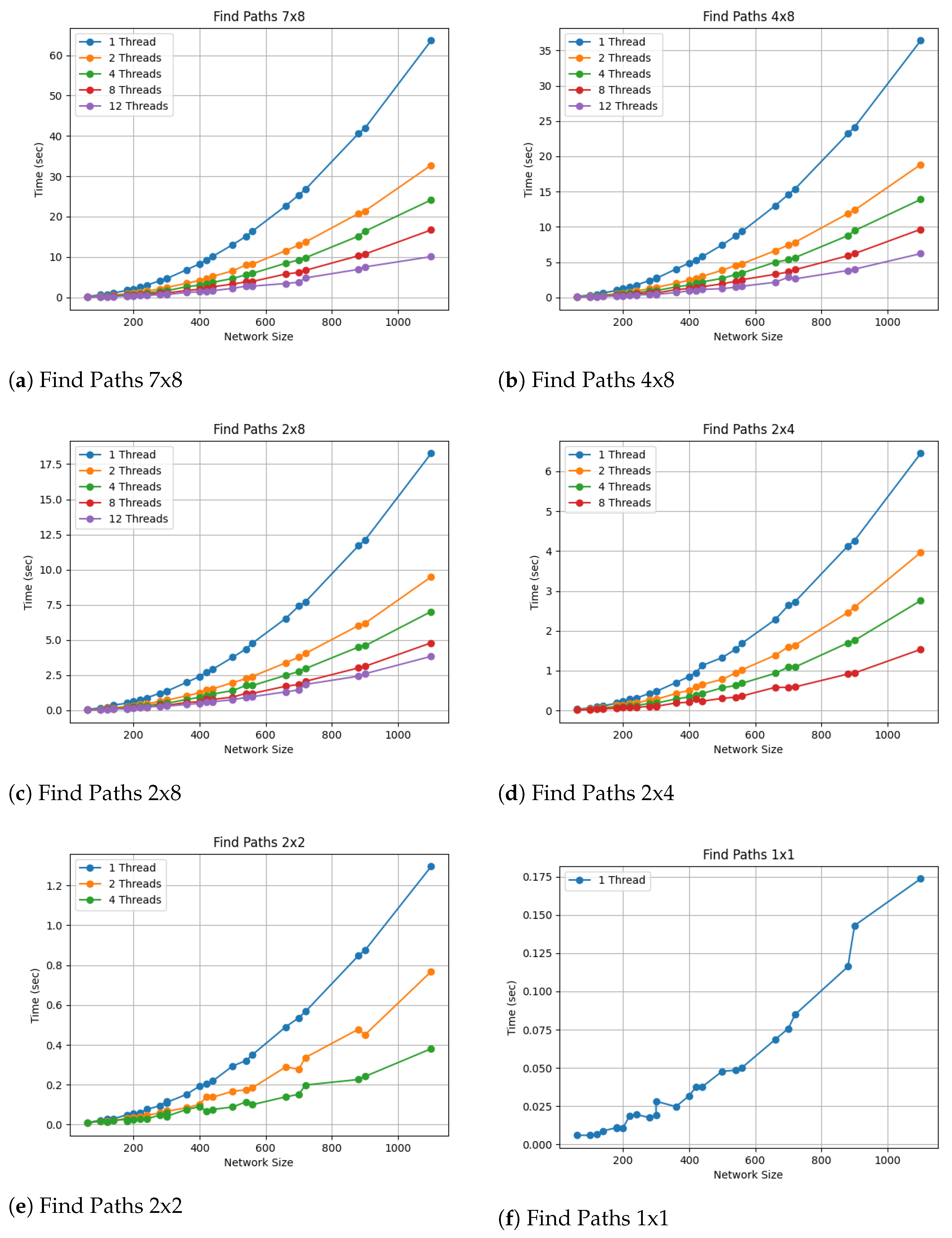
Figure 11 shows the completion time for attack path extraction for all the combinations of thread numbers, network sizes, and levels of knowledge of the intruder’s behavior.
We can observe in the results of the above experiments that for a small network size, it is feasible to export attack paths from an attack graph quite quickly and with low processing resource requirements. Conversely, for a fairly large network and/or insufficient knowledge about the tactics that the intruder will follow, more computing resources are required to obtain the desired results.
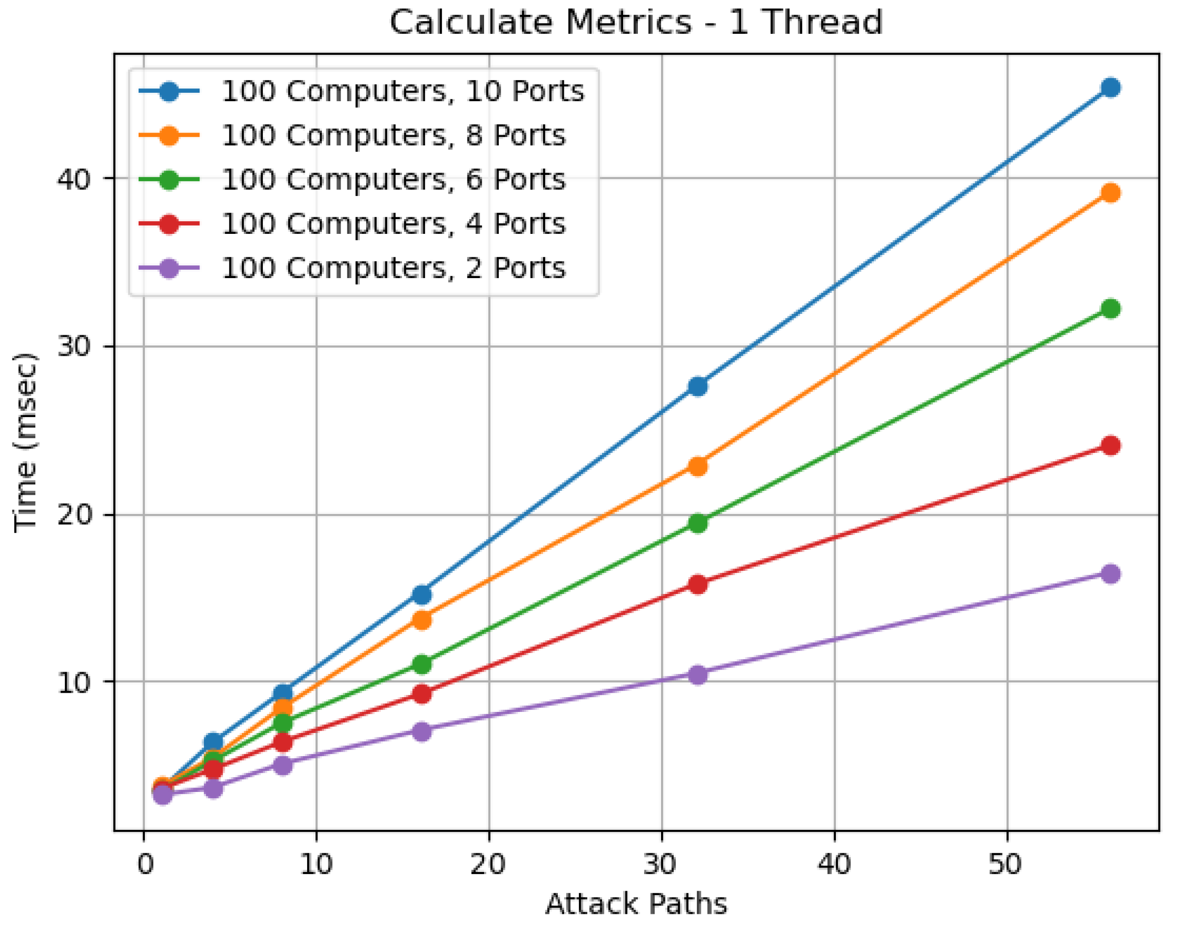
In addition, Figure 12 shows the time required to calculate the metrics, as described in Section 4. The figures depict the results for 100 hosts and 2, 4, 6, 8, and 10 open ports per host in 1, 4, 8, 16, 32, and 56 attack paths. As expected, the time required to calculate the metrics increases with the size of the network and the intruder behavior combinations. Metric calculation is a process that is repeated multiple times and needs to be as fast as possible. Additionally, the calculations of these metrics are in proportion to the number of attack paths. In order to solve this problem, we used multiple threads to process different attack paths. According to the experiments we performed, the calculation time of the metrics for each attack path tends to be less than 1 msec.
7. Conclusions and Future Work
In the present paper, we have presented a modeling approach that enables the explicit identification of intruders in the reconnaissance phase of an attack. Our analytical approach takes a multi-layer set of state diagrams that represent the intruder’s probable steps, the network topology, and the knowledge about the intruder’s preferred methodology as inputs. The output consists of a number of paths in the state diagrams that sufficiently describe the expected activity on the network. On top of this, we defined a set of metrics that enable the dynamic quantification of risk for a specific asset in the network given the location of the intruder.
It has to be noted that the modeling approach proposed herein is a scheme aimed for use by network administrators in the design and implementation of a holistic deception mechanism. This mechanism will include detecting reconnaissance activity and the automated application of deception countermeasures to protect the network. The decision engine of the mechanism will aim to provide the highest level of obfuscation with the minimum required resources. The basis of this mechanism is the modeling scheme presented herein, as it provides a concrete way to express the activity of an intruder, the expected next steps, and the risk for specific hosts/services of the protected system. All this structured information can significantly facilitate the application of the optimal deception-based mitigation solution.
In future work, we aim to design and implement an automated, deception-based mitigation mechanism for reconnaissance. This will consist of (i) a reconnaissance activity detection mechanism that will place the detected intruder on a specific node on the expected paths, (ii) a deception engine that will include generic implementations for most deception techniques available in the literature, and (iii) a decision engine that will automatically decide deception techniques to be applied according to the results of the detection mechanism. All the aforementioned methods will employ the proposed modeling approach described herein to represent and communicate reconnaissance activity.
Author Contributions
Conceptualization, I.B. and G.S.; methodology, I.B.; software, I.B.; validation, G.S.; writing—original draft preparation, I.B.; writing—review and editing, G.S. amd I.A.; visualization, I.B.; supervision, G.S. and I.A. All authors have read and agreed to the published version of the manuscript.
Funding
This research received no external funding.
Data Availability Statement
Data sharing not applicable.
Conflicts of Interest
The authors declare no conflict of interest.
Appendix A. Host Discovery and Port Scanning Graphs
Figure A1.
Host Discovery.

Figure A2.
Port Scanning.

Figure A3.
ICMP Host Discovery.

Figure A4.
TCP Host Discovery.

Figure A5.
UDP Host Discovery.

Figure A6.
TCP port scanning.

Figure A7.
UDP port scanning.

Figure A8.
ICMP Host Discovery.

Figure A9.
TCP Host Discovery.

Figure A10.
UDP Ping Host Discovery.

Figure A11.
TCP Connect Port Scanning.

Figure A12.
TCP Port Scanning.

Figure A13.
UDP Port Scanning.

References
- Filiol, E.; Mercaldo, F.; Santone, A. A method for automatic penetration testing and mitigation: A red hat approach. Procedia Comput. Sci. 2021, 192, 2039–2046. [Google Scholar] [CrossRef]
- Haan, G.H.K. Detection of portscans using IP header data. In Proceedings of TBRC’05; 2005. [Google Scholar]
- Patel, S.K.; Sonker, A. Rule-based network intrusion detection system for port scanning with efficient port scan detection rules using snort. Int. J. Future Gener. Commun. Netw. 2016, 9, 339–350. [Google Scholar] [CrossRef]
- De Vivo, M.; Carrasco, E.; Isern, G.; De Vivo, G.O. A review of port scanning techniques. ACM SIGCOMM Comput. Commun. Rev. 1999, 29, 41–48. [Google Scholar] [CrossRef]
- Vugrin, E.D.; Cruz, J.; Reedy, C.; Tarman, T.; Pinar, A. Cyber threat modeling and validation: Port scanning and detection. In Proceedings of the 7th Symposium on Hot Topics in the Science of Security, Lawrence, KS, USA, 21–23 September 2020; pp. 1–10. [Google Scholar]
- Ananin, E.V.; Nikishova, A.V.; Kozhevnikova, I.S. Port scanning detection based on anomalies. In Proceedings of the 2017 Dynamics of Systems, Mechanisms and Machines (Dynamics), Omsk, Russia, 14–16 November 2017; pp. 1–5. [Google Scholar]
- Bhuyan, M.H.; Bhattacharyya, D.K.; Kalita, J.K. Surveying port scans and their detection methodologies. Comput. J. 2011, 54, 1565–1581. [Google Scholar] [CrossRef]
- Barnett, R.J.; Irwin, B. Towards a taxonomy of network scanning techniques. In Proceedings of the 2008 Annual Research Conference of the South African Institute of Computer Scientists and Information Technologists on IT Research in Developing Countries: Riding the Wave of Technology, Wilderness, South Africa, 6–8 October 2008; pp. 1–7. [Google Scholar]
- Lee, C.B.; Roedel, C.; Silenok, E. Detection and Characterization of Port Scan Attacks; Univeristy of California, Department of Computer Science and Engineering: Los Angeles, CA, USA, 2003. [Google Scholar]
- Kanlayasiri, U.; Sanguanpong, S.; Jaratmanachot, W. A rule-based approach for port scanning detection. In Proceedings of the 23rd Electrical Engineering Conference, Chiang Mai, Thailand, 2000; pp. 485–488. [Google Scholar]
- Doynikova, E.; Novikova, E.; Kotenko, I. Attacker behaviour forecasting using methods of intelligent data analysis: A comparative review and prospects. Information 2020, 11, 168. [Google Scholar] [CrossRef] [Green Version]
- Katipally, R.; Yang, L.; Liu, A. Attacker behavior analysis in multi-stage attack detection system. In Proceedings of the Seventh Annual Workshop on Cyber Security and Information Intelligence Research, Oak Ridge, TN, USA, 12–14 October 2011; p. 1. [Google Scholar]
- Balram, S.; Wiscy, M. Detection of TCP SYN scanning using packet counts and neural network. In Proceedings of the 2008 IEEE International Conference on Signal Image Technology and Internet Based Systems, Bali, Indonesia, 30 November–3 December 2008; pp. 646–649. [Google Scholar]
- Trassare, S.T.; Beverly, R.; Alderson, D. A technique for network topology deception. In Proceedings of the MILCOM 2013–2013 IEEE Military Communications Conference, San Diego, CA, USA, 18–20 November 2013; pp. 1795–1800. [Google Scholar]
- Albanese, M.; Battista, E.; Jajodia, S. A deception based approach for defeating OS and service fingerprinting. In Proceedings of the 2015 IEEE Conference on Communications and Network Security (CNS), Florence, Italy, 28–30 September 2015; pp. 317–325. [Google Scholar]
- Le Malécot, E. MitiBox: Camouflage and deception for network scan mitigation. In Proceedings of the 4th USENIX Workshop on Hot Topics in Security (HotSec), Montreal, QC, Canada, 11 August 2009. [Google Scholar]
- Lee, S.; Im, S.Y.; Shin, S.H.; Roh, B.H.; Lee, C. Implementation and vulnerability test of stealth port scanning attacks using ZMap of censys engine. In Proceedings of the 2016 International Conference on Information and Communication Technology Convergence (ICTC), Jeju, Republic of Korea, 19–21 October 2016; pp. 681–683. [Google Scholar]
- Dabbagh, M.; Ghandour, A.J.; Fawaz, K.; El Hajj, W.; Hajj, H. Slow port scanning detection. In Proceedings of the 2011 7th International Conference on Information Assurance and Security (IAS), Melacca, Malaysia, 5–8 December 2011; pp. 228–233. [Google Scholar]
- Gadge, J.; Patil, A.A. Port scan detection. In Proceedings of the 2008 16th IEEE International Conference on Networks, New Delhi, India, 12–14 December 2008; pp. 1–6. [Google Scholar]
- Algaolahi, A.Q.; Hasan, A.A.; Sallam, A.; Sharaf, A.M.; Abdu, A.A.; Alqadi, A.A. Port-Scanning Attack Detection Using Supervised Machine Learning Classifiers. In Proceedings of the 2021 1st International Conference on Emerging Smart Technologies and Applications (eSmarTA), Sana’a, Yemen, 10–12 August 2021; pp. 1–5. [Google Scholar]
- Pham, L.H.; Albanese, M.; Chadha, R.; Chiang, C.Y.J.; Venkatesan, S.; Kamhoua, C.; Leslie, N. A quantitative framework to model reconnaissance by stealthy attackers and support deception-based defenses. In Proceedings of the 2020 IEEE Conference on Communications and Network Security (CNS), Avignon, France, 29 June–1 July 2020; pp. 1–9. [Google Scholar]
- Steingartner, W.; Galinec, D.; Kozina, A. Threat defense: Cyber deception approach and education for resilience in hybrid threats model. Symmetry 2021, 13, 597. [Google Scholar] [CrossRef]
Figure 1.
Sample State Diagram.

Figure 2.
Sample State Diagram Level 2.

Figure 3.
State Diagram Encapsulation.

Figure 4.
Host discovery and port scanning.

Figure 5.
Average hops to a node.

Figure 6.
Node Occurrence Probability.

Figure 7.
Components.

Figure 8.
Attack graph.

Figure 9.
Echo Request and SYN Scan Path.

Figure 10.
Echo Request and FIN Scan Path.

Figure 11.
Find Attack Paths.

Figure 12.
Calculate Metrics.


Table 1.
Types of state diagram vertices.
| State | Symbol | Properties |
|---|---|---|
| Simple |  | initial: final: intermediate: |
| Complex |  | , |
| Intruder decision driven |  | k = 1, |
| Network input driven |  | k = 1, |
Table 2.
Parameters and values of experiments.
| Parameter | Values |
|---|---|
| Number of Attack Paths | 1 × 1, 2 × 2, 2 × 4, 2 × 8, 4 × 8, 7 × 8 |
| CPU Threads | 1, 2, 4, 8, 12 |
| Computers | 20, 40, 60, 80, 100 |
| Open Ports | 2, 4, 6, 8, 10 |
Disclaimer/Publisher’s Note: The statements, opinions and data contained in all publications are solely those of the individual author(s) and contributor(s) and not of MDPI and/or the editor(s). MDPI and/or the editor(s) disclaim responsibility for any injury to people or property resulting from any ideas, methods, instructions or products referred to in the content. |
© 2023 by the authors. Licensee MDPI, Basel, Switzerland. This article is an open access article distributed under the terms and conditions of the Creative Commons Attribution (CC BY) license (https://creativecommons.org/licenses/by/4.0/).
Share and Cite
MDPI and ACS Style
Belalis, I.; Spathoulas, G.; Anagnostopoulos, I. Modeling Intruder Reconnaissance Behavior through State Diagrams to Support Defensive Deception. J. Cybersecur. Priv. 2023, 3, 275-302. https://doi.org/10.3390/jcp3020015
AMA Style
Belalis I, Spathoulas G, Anagnostopoulos I. Modeling Intruder Reconnaissance Behavior through State Diagrams to Support Defensive Deception. Journal of Cybersecurity and Privacy. 2023; 3(2):275-302. https://doi.org/10.3390/jcp3020015
Chicago/Turabian StyleBelalis, Ilias, Georgios Spathoulas, and Ioannis Anagnostopoulos. 2023. "Modeling Intruder Reconnaissance Behavior through State Diagrams to Support Defensive Deception" Journal of Cybersecurity and Privacy 3, no. 2: 275-302. https://doi.org/10.3390/jcp3020015