

Experimental and Computational Analyses of Sustainable Approaches in Railways
by
 , , , and
Mohammad Adnan Farooq
1 ,
,
Naveen Kumar Meena
2 ,
,
Piyush Punetha
1 ,
,
Sanjay Nimbalkar
1,3,* and
and
Nelson Lam
4 1
School of Civil and Environmental Engineering, University of Technology Sydney, Ultimo, NSW 2007, Australia
2
Beca, Sydney, NSW 2000, Australia
3
Department of Civil Engineering, Indian Institute of Technology Bombay, Powai, Mumbai 400076, India
4
Department of Infrastructure Engineering, University of Melbourne, Parkville, VIC 3010, Australia
*
Author to whom correspondence should be addressed.
Infrastructures 2024, 9(3), 53; https://doi.org/10.3390/infrastructures9030053
Submission received: 25 January 2024
/
Revised: 26 February 2024
/
Accepted: 3 March 2024
/
Published: 8 March 2024
(This article belongs to the Special Issue Railway Infrastructure Resilience: Addressing Challenges and Ensuring Sustainability)
Abstract
:Railway transportation is widely recognized as an environment-friendly and sustainable means for conveying freight and passengers over long distances. This article investigates the effectiveness of utilizing scrap tire rubber granules and geosynthetics to enhance track performance in response to the growing demands for railway transport and the consequent escalation of train-induced loading. A multi-faceted methodology, incorporating experimental, numerical, and analytical techniques, is employed to examine the efficacy of these sustainable approaches. Results from three-dimensional (3D) finite element (FE) analyses conducted on slab tracks for high-speed railways reveal that the addition of a resilient layer, comprising scrap tire rubber granules, reduces vertical stress within the track substructure. Laboratory investigations on an innovative composite material consisting of soil, scrap rubber granules, and polyurethane demonstrate its potential to enhance track performance. Findings from two-dimensional (2D) FE analyses conducted on pile-supported railway embankments highlight an enhanced transfer of load to the pile head following the installation of a geogrid layer at the embankment base. Finally, the results from the analytical approach indicate a reduction in track settlement and a decrease in the track geometry degradation rate on reinforcing the ballast layer with 3D cellular geoinclusion. The novelty of this study lies in the comprehensive assessment of the innovative composite material under drained and cyclic loading conditions, the investigation of the influence of train loading on geosynthetic tension and the load transfer mechanism in railway embankments, and the development of an innovative computational methodology capable of assessing the effectiveness of 3D cellular inclusions in improving the ballasted railway track performance. The findings from this article underscore the effectiveness of these sustainable approaches in mitigating the challenges posed by increased loads on railway tracks, providing valuable insights for the ongoing efforts to optimize railway transportation infrastructure.
1. Introduction
In 2015, the United Nations (UN) initiated the sustainable development program ‘Transforming our World: The 2030 Agenda for Sustainable Development’, comprising ‘17 Sustainable Development Goals (SDGs)’ and ‘169 targets’ [1]. This program has stimulated global efforts to devise practical solutions for implementing the SDGs in the transport infrastructure sector. While railway transportation is recognized for its environment-friendly and sustainable attributes during the operation phase, such as emitting lower carbon dioxide gas and consuming less energy compared to alternative modes like road, air or marine transport [2], it is imperative to acknowledge the significant environmental impacts during its construction and maintenance phases [3]. Addressing these impacts is essential to improve the overall sustainability of railway transportation.
The railway system is undeniably vital for transporting passengers and goods along major corridors in countries like Australia, Brazil, Canada, China, India, Japan, Russia, South Africa, the United States, and the European Union. In order to meet the escalating demand for freight and public transport, the railway industries are consistently embracing advanced technologies. This has resulted in the development of faster passenger trains and increased capacity for freight trains. The increased train speed and higher tonnage in recent years have escalated the deterioration and irrecoverable (plastic) deformation in the substructure components. As a result, frequent maintenance or even reconstruction has become necessary [4]. Therefore, it is imperative to upgrade the existing tracks and build new ones using innovative materials and technology to cope with the increased traffic-induced stresses.
The railway industry is currently exploring viable measures for strengthening the track and reducing the need for frequent maintenance. These remedial measures should not only be cost-effective but also align with the sustainability of the railway infrastructure, taking into account increasing environmental concerns. This is because the construction and maintenance of railway tracks (ballasted and ballastless) typically require a large amount of natural aggregates from the quarries, which are depleting at a rapid pace. Additionally, the extraction, processing, and transportation of the aggregates make a notable contribution to greenhouse gas emissions [5]. Disposing of waste materials from maintenance operations amplifies the environmental impact. Therefore, solutions must aim to minimize the consumption of natural aggregates during the construction and maintenance operations or replace these aggregates with sustainable materials.
Recently, the use of discarded tires as a construction material has gained attention since the accumulation of these tires poses both financial burdens and environmental risks [6]. These scrap tires can be used either in the form of aggregates (also termed rubber granules), or as whole tires (also known as recycled tires). Scrap tires offer several benefits when used in construction, including their low unit weight, effective drainage, excellent thermal insulation, high compressibility, and notable vibration-damping qualities [7,8]. These attributes have led to an increased adoption of rubber granules for various applications, such as subgrade and embankment materials, trench fill material [9,10], drainage layers in highways [11], vibration attenuation in railway tracks [12], asphalt rubber manufacture [13], and subgrade insulation in roads [14], among other uses. It is believed that scrap tires have minimal impact on soil and groundwater quality since they are manufactured using inert (non-reactive) substances. Consequently, scrap tires offer a sustainable solution that can be employed in railway tracks to improve their overall performance.
Another sustainable approach to enhance the stability and lifespan of railway tracks is the utilization of geosynthetics, which are polymeric materials widely employed in various applications, encompassing soil reinforcement, filtration, slope stabilization, drainage, and seepage control, among others [15]. Geosynthetics have become an essential element in numerous geotechnical engineering projects and have proven successful in improving railway track stability, particularly built on soft subgrade [16]. Previous studies have demonstrated that integrating geosynthetics, like geogrids, into railway tracks leads to a reduction in track settlement [17], thereby potentially reducing the need for frequent maintenance. Furthermore, geosynthetic reinforcement allows the construction of thinner granular layers without compromising the track performance [17], resulting in the decreased demand for natural aggregates and promoting sustainability.
It is imperative to evaluate the efficacy of these sustainable approaches in the actual railway tracks. Their performance in the field can be effectively monitored using the radio frequency identification (RFID) sensors [18,19]. These sensors not only monitor the performance of the various track components but also facilitate maintenance planning, thereby minimizing associated costs and contributing to the sustainability of the railway tracks. Despite ongoing advancements in structural health monitoring (SHM) technology, deciphering a vast amount of data collected by sophisticated SHM systems to glean meaningful insights about the condition of structures remains a formidable task. In an effort to address this challenge, an approach utilizing probabilistic data-driven damage detection method within the sparse Bayesian learning (SBL) framework has been used by some researchers [20,21,22]. These data modeling and performance evaluation methods can also be employed to evaluate the performance of sustainable railways. Nevertheless, the use of RFID sensors, the data modeling, and the performance evaluation methods are beyond the scope of this study.
Overall, the literature review underscores a need for further investigation into sustainable materials and technologies aimed at improving the railway track performance. Despite advancements in technology and the increasing demand for high-speed and heavy-haul trains, there is a gap in research on effective measures to strengthen railway tracks to withstand increased loading induced by these trains. Although there is acknowledgment of the environmental concerns associated with the consumption of natural aggregates in railway track construction and maintenance, there is an insufficient exploration of sustainable alternatives. Specifically, the potential use of discarded tires and geosynthetics as sustainable materials needs further investigation.
This article delves into two sustainable approaches for enhancing the railway track performance: the utilization of scrap rubber granules and geosynthetics. The adequacy of these strategies is assessed through experimental, analytical, and numerical methods. Initially, the feasibility of using scrap rubber granules in the track substructure is investigated through laboratory and numerical approaches. Subsequently, the influence of geogrids on the load transfer mechanism in pile-supported railway embankments is explored through finite element (FE) analyses. Finally, the efficacy of employing 3D cellular inclusions to enhance the ballasted railway track performance is assessed using an innovative rheological track model. It must be noted that these approaches (i.e., scrap rubber granules and geosynthetics) are selected based on their potential to provide effective and sustainable solutions. These methods have been chosen after a comprehensive review of available options, considering factors, such as environmental impact, cost-effectiveness, and feasibility.
2. Enhancing Railway Track Performance: Utilizing Scrap Rubber and Innovative Materials in Track Substructure
In Australia, more than 50 million tires are being disposed of each year [23]. Recycling this waste rubber can contribute to energy conservation and the reduction of climate pollutants. Hence, it is now advisable to explore the use of discarded rubber as a potential geomaterial in diverse civil engineering applications [24,25]. Scrap rubber has been utilized in a few railway projects to reduce vibrations in the surrounding areas due to train operations [26,27]. D’Andrea et al. [28] conducted a case study using hot mix asphalt, substituting traditional aggregates with waste tire rubber granulates. The study revealed that the use of rubber mix aggregates effectively reduces ground vibration induced by the trains. Zoccali et al. [29] conducted a numerical analysis to evaluate the vibration-damping potential of trenches with varying dimensions and infilled materials. The study found that soil—bentonite mixture with scrap rubber significantly reduces the vibration, even in shorter trenches.
In situ experiments conducted on a ballasted track, which included a layer of rubber granules beneath the ballast layers, indicated that the performance of rubber granules is akin to that of ballast mats [30]. In another investigation, subballast on a concrete railway bridge was substituted with rubber granules, resulting in a 63% decrease in sleeper acceleration [31]. In another investigation by Farooq et al. [23], a 50% reduction in track vibrations was observed by the inclusion of a 25 mm thick layer, comprising rubber granules, beneath the base layer of the ballastless track. Additionally, a 42% reduction in track vibrations was reported when the same layer was introduced beneath the subballast (or capping) layer of a ballasted track. Fathali et al. [32] found that 10% rubber granules lowered the ballast settlement and particle breakage by 6% and 47%, respectively. However, at a rubber granule content higher than 20%, decreased shear strength and increased settlement of ballast were observed. Sol-Sánchez et al. [33] reported reduced track settlement with 10% rubber granules (by volume proportion). Esmaeili et al. [34] observed increased sand-fouled ballast settlements with rubber granules. This discrepancy underscores the need for comprehensive research on rubber—granular soil blends. The subsequent sections explore the effectiveness of using rubber granules as a layer and rubber granules in combination with granular materials in the track substructure through numerical and laboratory investigations.
2.1. Finite Element Approach
2.1.1. Model Development
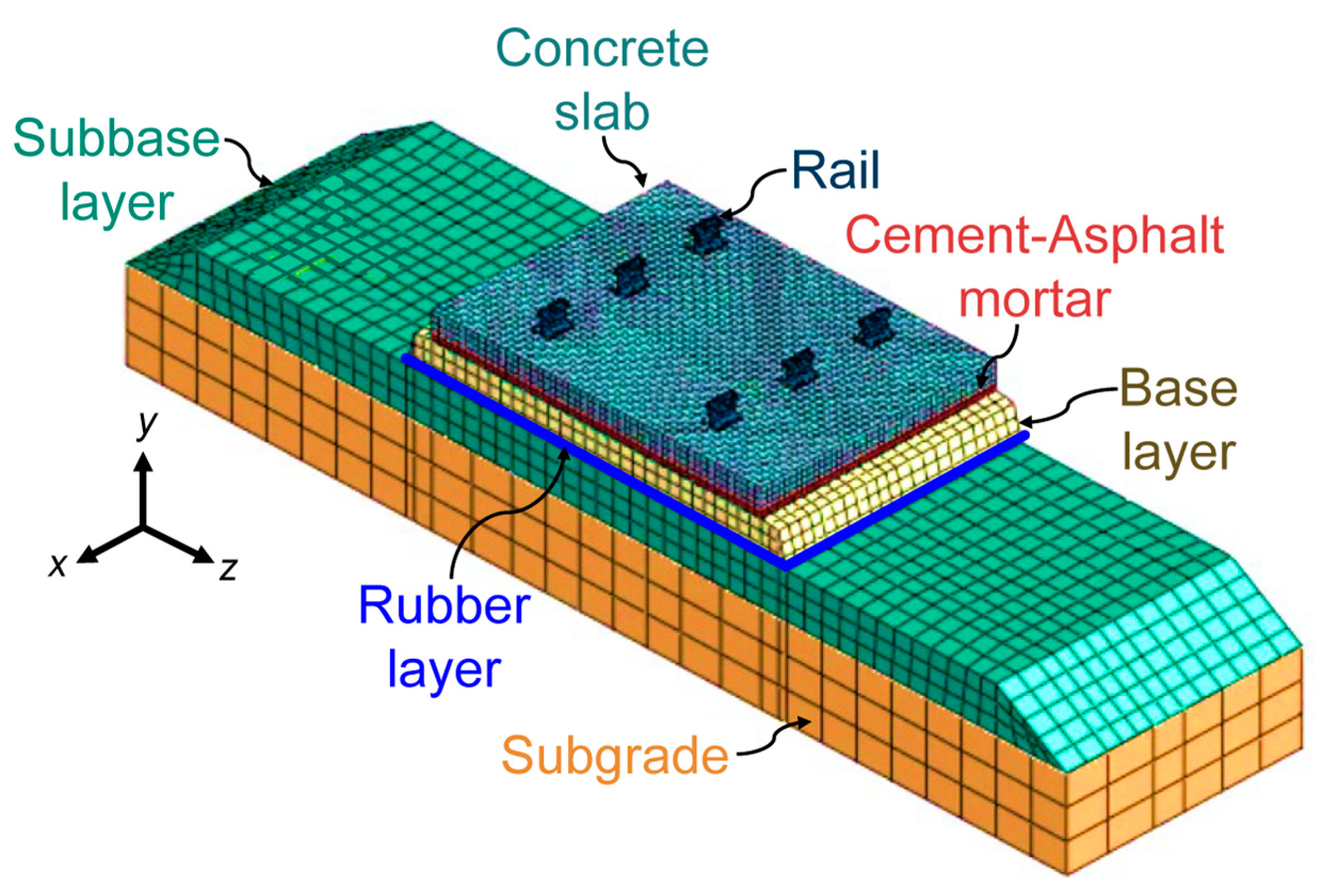
This section explores the effect of adding a resilient layer consisting of rubber granules on the behavior of slab tracks employed in high-speed railways using FE analyses. To this end, a three-dimensional FE model for a slab track is developed using FE analysis software ABAQUS (Version 2018) [35]. In this model, the rail, concrete slab, cement asphalt mortar (CAM), and base layer (see Figure 1) are considered linear elastic materials, whereas the subbase is represented as an elastoplastic material which follows the Drucker–Prager yielding criterion. The behavior of rubber material is simulated using the hyperelastic constitutive model. The subgrade is modeled as a material exhibiting linear elastic perfectly plastic behavior, complying with the Mohr–Coulomb failure criterion. The interaction between different track layers is simulated using a surface-to-surface contact approach.
The slab track configuration comprises 15,116 elements and 26,972 nodes, utilizing eight-noded hexahedral linear brick elements (first-order) with reduced integration and hourglass control (C3D8R) to streamline the analysis process. This reduced integration minimizes the computational load by employing fewer Gaussian coordinates. The base of the slab track is supported with pinned boundary conditions, prohibiting displacement in the x, y, and z directions. Additionally, displacement in the z and x directions is restricted in the x-y and y-z planes of the slab track, respectively. Global element sizes of 0.05, 0.1, 0.1, 0.15, 0.15, and 0.3 m are assigned to the rail, concrete slab, CAM, base layer, subbase layer, and subgrade, respectively. The mesh density increases from the top to the bottom layers of the slab track to enable a more detailed computational analysis of the upper layers. The interaction between layers is simulated using surface-to-surface contact with ‘hard’ normal contact and a penalty-based tangential behavior with a coefficient of friction set at 0.5. The material parameters of various components of a slab track are listed in Table 1. A detailed explanation of the methodology, including validation, can also be found in previous works [23].
2.1.2. Results and Discussion
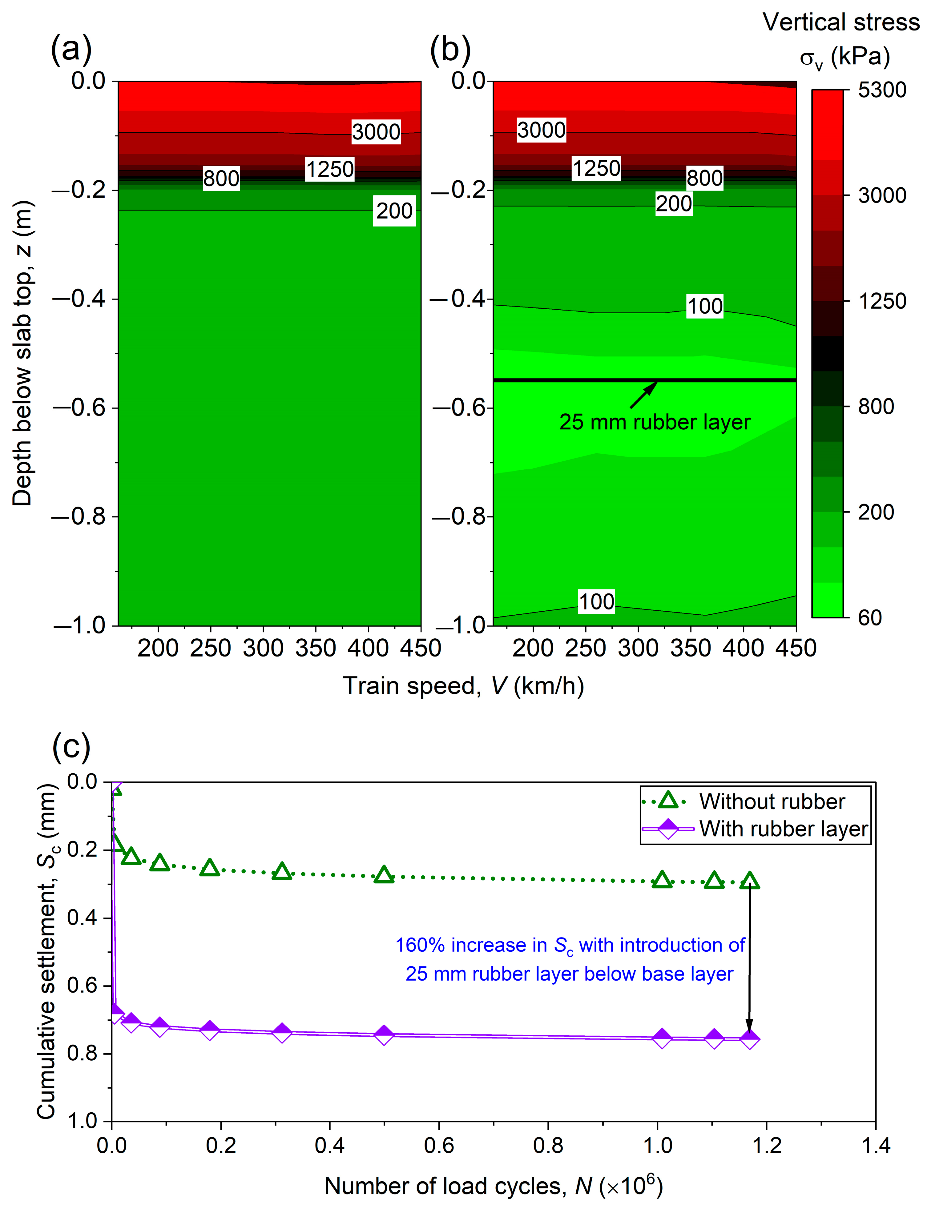
Figure 2a,b depicts the changes in vertical stress (σv) with depth for the slab track under varying train speeds (V). It is apparent from the figures that the rubber layer introduction lowers the σv, particularly for depths extending beyond 0.4 m beneath the top surface of the slab, regardless of the train speed. For example, the σv decreases from 200 kPa to approximately 100 kPa at a depth of 0.42 m beneath the slab top (at a train speed of 250 km/h) when the rubber layer is added. Thus, a drastic reduction in the vertical stress levels is observed with the addition of a rubber layer, which is crucial for the stability of lower track layers, such as subgrade.
Figure 2c shows the comparison between the cumulative settlement (Sc) at the top of the slab track, without the rubber layer and with a 25 mm rubber layer placed beneath the base layer. The inclusion of the rubber layer increases the Sc by 160%, recorded after completing 1.2 million load cycles (N). However, it is important to note that the displacement at the end of the test is below 1 mm, which is negligible.
Given the numerical outcomes clearly indicating that the inclusion of rubber as a substructure layer increases the cumulative settlement, a laboratory investigation is carried out to evaluate the performance of rubber granules mixed with granular soil (see Section 2.2). In addition, a novel sustainable material for the railway tracks is proposed in Section 2.2 which comprises a mixture of granular soil and rubber granules treated with polyurethane.
2.2. Experimental Approach
The main aim of this section is to showcase an innovative material comprising granular soil, scrap rubber granules, and polyurethane foam adhesive (PFA), which can serve as a foundational material in both ballasted and ballastless tracks. The performance of this innovative material is compared with granular soil and granular soil mixed with scrap rubber granules. Introducing these rubber granules into the base layer material has the potential to address issues related to vibration and noise, contributing to a more sustainable construction approach. Additionally, the inclusion of polyurethane serves as an adhesive, helping to minimize deformation in the composite material. This laboratory investigation evaluates the potential of the composite material in enhancing track performance, which adds to the existing body of knowledge on track engineering materials.
2.2.1. Materials and Methods
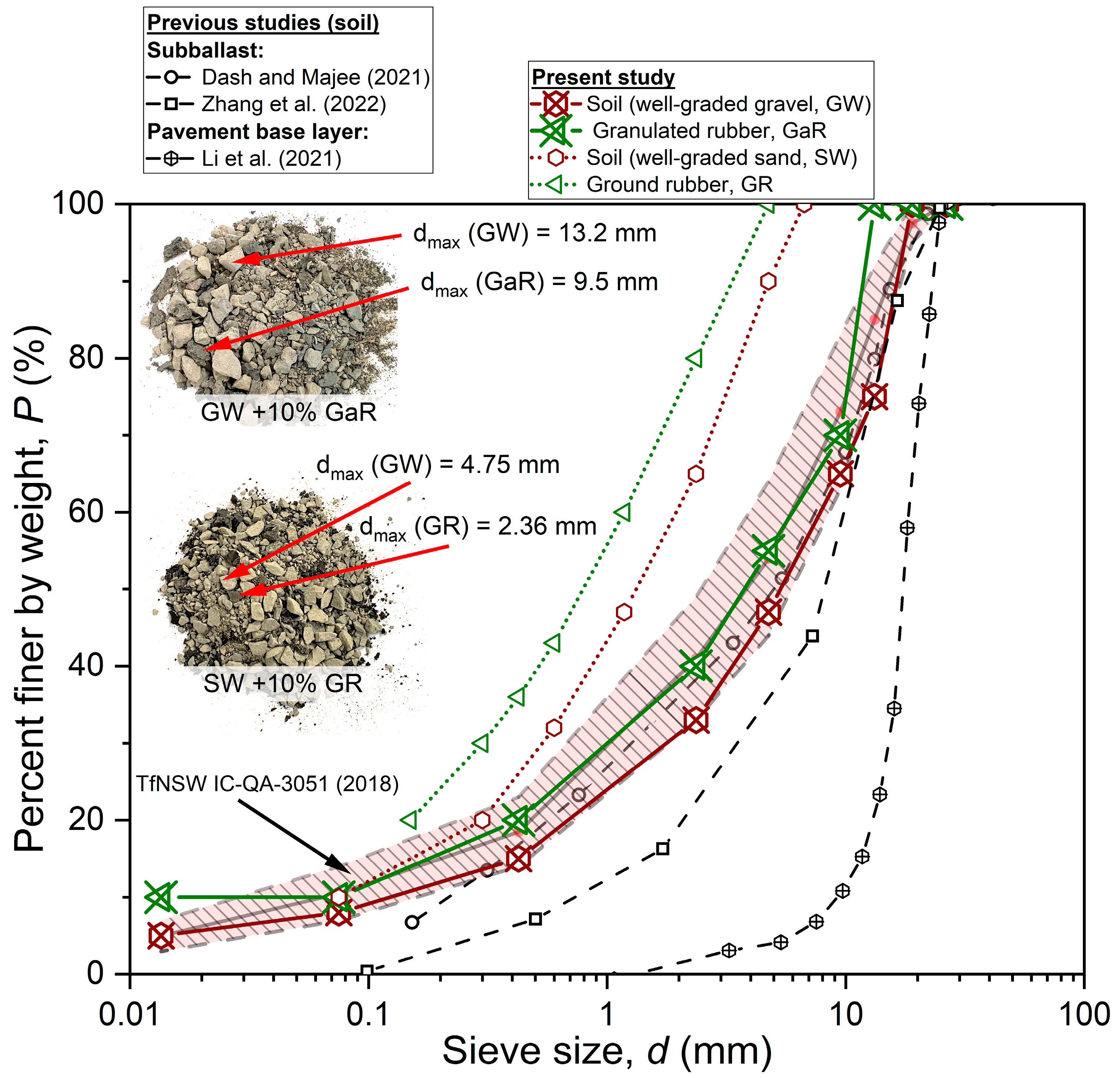
Figure 3 illustrates the particle size distribution (PSD) curves of two soil and rubber granule types adopted in this study. For the sake of comparison, Figure 3 also includes the PSD curves adopted in previous studies for subballast [38,39] and road base material [40]. The uniformity coefficient (Cu) and coefficient of curvature (Cc) of gravelly soil in the present study are 62.3 and 3, respectively. This contrasts with the Cu and Cc values of 24.2 and 2.12 reported by Dash and Majee [38], as well as the values of 37.5 and 1.5 reported by Zhang et al. [39]. Two PSD curves for soil and rubber are employed to meet the specified criteria for the minimum sample size ratio, which considers the specimen diameter in relation to the nominal particle size. The two soil types are classified as well-graded gravel (GW) and well-graded sand (SW), following the ASTM D2487 standard [41]. More details on the material description can be found elsewhere [24,42,43].
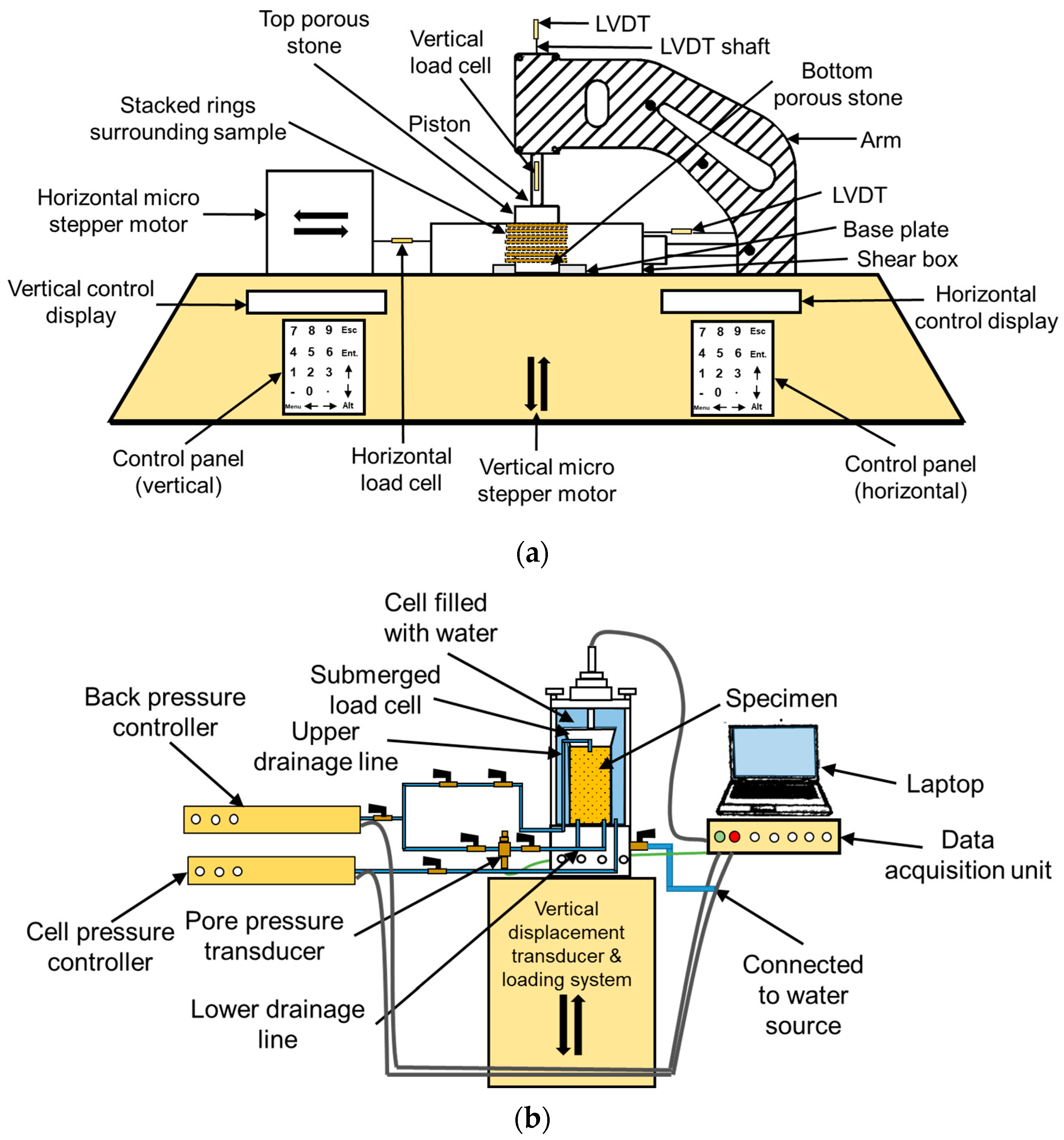
Static direct simple shear (SDSS) tests were conducted using a direct simple shear apparatus (Figure 4a) to determine the optimum dosage of scrap rubber granules and PFA. The optimal dosages of rubber and PFA were utilized to prepare specimens which were subjected to cyclic testing using advanced dynamic triaxial equipment (Figure 4b) under a cyclic deviatoric stress (qc) of 300 kPa, effective confining stress () of 10 kPa, and cyclic loading frequency (fc) of 4 Hz. The above-mentioned qc and exist on the base layer of a ballastless track, and fc of 4 Hz represents a train speed (V) of 260 km/h, following the approach suggested by Farooq and Nimbalkar [22] and Čebašek, et al. [36]. Two types of mixtures, viz., untreated soil–rubber mixture (USRM) and treated soil–rubber mixture (TSRM), were prepared with varying rubber content. It must be noted that the treated mixtures here refer to the mixtures prepared with PFA. Both SDSS and cyclic triaxial tests were conducted under drained conditions. A detailed description of the testing methodology for SDSS and cyclic triaxial tests can be found elsewhere [24,42].
2.2.2. Results and Discussion
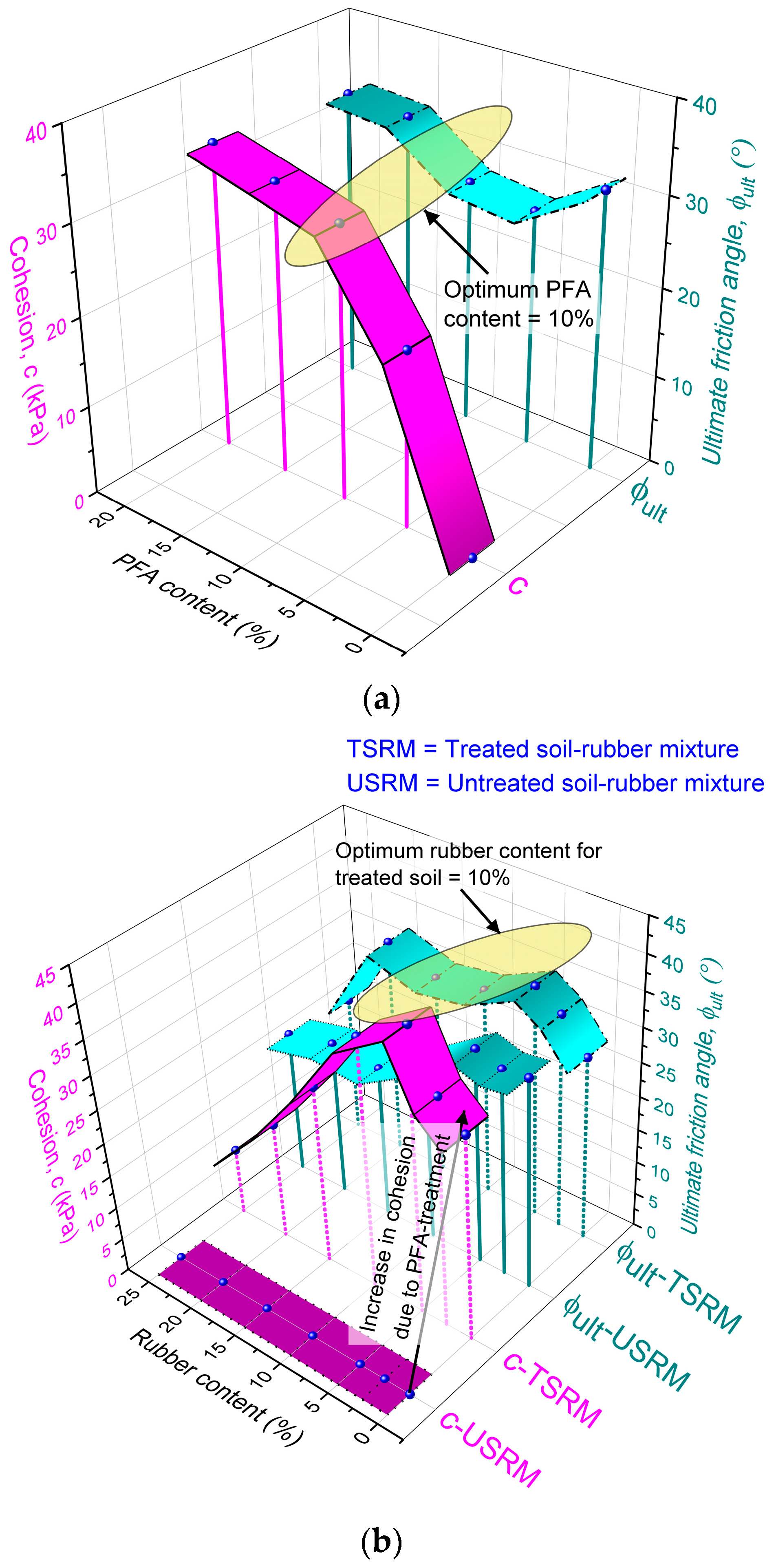
Figure 5a displays the changes in cohesion (c) and the ultimate friction angle (ϕult) in PFA-treated soil, with varying PFA content (PFA = 0–20%). The results indicate that soil treatment with 5% PFA enhanced the soil’s cohesion by 20 kPa while simultaneously reducing ϕult from 31.2° to 26.6°. This increment in cohesion, without significantly influencing the friction angle, is consistent with the results reported in previous work by Xiao et al. [44]. The study attributes a slight reduction in the ϕult to decreased relative mobility among particles and a subsequent decline in the frictional interlock due to PFA treatment. The non-foaming PFA used in this research effectively coated the soil/rubber surfaces, enhancing their binding without filling the voids.
Beyond the 5% PFA threshold, both c and consistently increased, with optimum PFA dosage at around 10% PFA. The TSRM’s were prepared by mixing soil with 10% PFA and rubber varying between 0 and 25%. The changes in c and for TSRM with varying rubber contents are presented in Figure 5b. Both c and exhibited an increase with the addition of rubber, reaching maximum values at 5% rubber content with a peak c of 41.6 kPa and of 34.3°. However, beyond the 5% rubber threshold, c and decreased as the rubber content increased. With rubber contents below 5%, finer rubber particles fill soil voids, aiding contact force transfer through the parent soil skeleton. The presence of fine rubber granules inside the voids introduces additional support against deformation, leading to elevated values of c and . At rubber dosages exceeding 5%, the rubber becomes part of the load-bearing structure, reducing soil particle interlock and resulting in decreased . In contrast, Zhang et al. [39] observed that the addition of rubber in the form of tire chips to subballast resulted in an increase in the internal friction angle under monotonic loading conditions. This variation could be attributed to the different types of rubber used in their study. Nevertheless, these results suggest an optimal rubber content of 10% for TSRM, as indicated by the highlighted yellow area shown in Figure 5b.
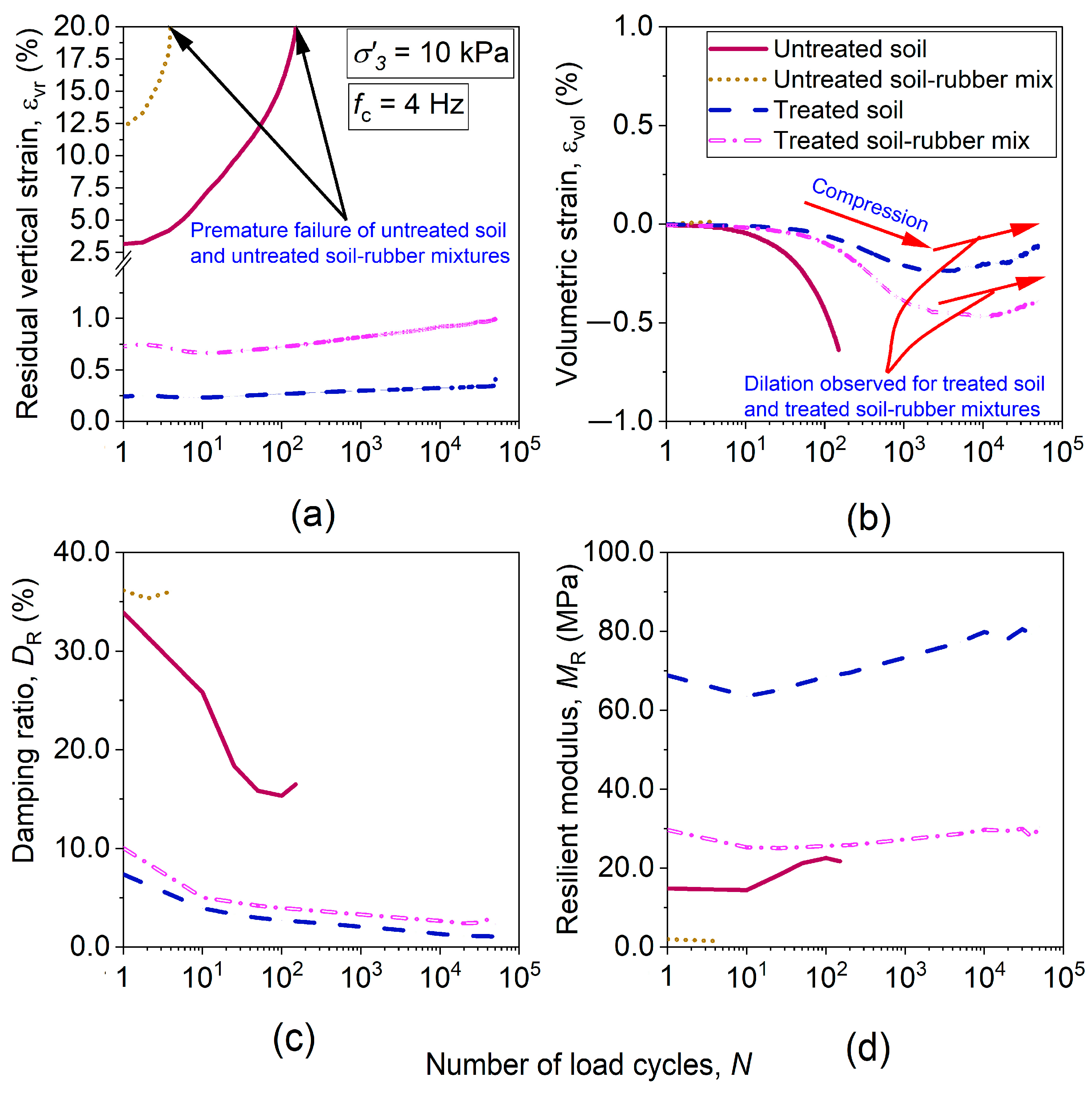
Figure 6 illustrates the variation in residual vertical strain () volumetric strain (), resilient modulus (MR), and damping ratio (DR) of four types of mixtures, viz., untreated soil, treated soil, USRM, and TSRM. It can be seen in Figure 6a that both the untreated soil and USRM failed prematurely within 150 and 4 load cycles, respectively. The PFA treatment of both soil and soil–rubber mixtures helped to reduce the considerably, and the specimens sustained 50,000 load cycles with of less than 1% at the completion of the test. The of soil was compressive, whereas the of rubber-mixed soil was nearly zero (see Figure 6b). With PFA treatment, although the initial of both treated soil and TSRM was compressive, it transited to dilative behavior. This dilative behavior can be attributed to the strength gain due to PFA treatment. Although the DR of untreated soil and USRM was substantially higher than that of treated mixtures, the MR was less, especially for USRM (see Figure 6c, d). The addition of rubber to granular soil reduces the resilient modulus and increases the vertical strain of the mix, which is consistent with a previous study by Zhang et al. [39]. The addition of rubber to treated soil decreased the MR by 62.6% but increased the DR by 118%. Hence, this TSRM proves to be the most suitable mix in striking a balance between , , DR, and MR. In conclusion, scrap rubber in granular form can be blended with soil to create sustainable track material, and the performance of this mixture can be further enhanced by incorporating PFA.
3. Use of Geosynthetics in Railway Tracks
This section explores the effectiveness of planar and 3D geosynthetics in enhancing the performance of railway tracks through numerical and analytical approaches. Firstly, the influence of geogrids on the load transfer mechanism in pile-supported railway embankments is explored using FE analyses. Subsequently, the efficacy of employing 3D cellular inclusions in improving the railway track behavior is assessed using rheological ballasted track model.
3.1. Use of Geogrid in Pile-Supported Railway Embankments
Rapid urbanization in several countries has led to an increased demand for the construction of new railway corridors [45,46,47]. This increased demand has compelled the construction of railway tracks on suboptimal soil with deficient engineering properties, such as low strength and high compressibility. Consequently, the railway industry is exploring innovative and sustainable solutions for constructing railway tracks on such soils. The geosynthetic-reinforced pile-supported (GRPS) embankment has emerged as a viable and sustainable solution for the construction of railway tracks on weak soils that possess poor engineering properties [48,49,50,51,52].
In GRPS embankments, a significant portion of the embankment load, including traffic load, is conveyed to rigid piles via the soil arching effect [53]. In these embankments, the settlement of fill material is more pronounced between piles, primarily owing to the stiffness disparity between the rigid piles and the surrounding soil. However, this settlement is constrained by the mobilization of shear stress within the embankment fill, described as the soil arching phenomenon. Alongside soil arching, a part of the total load is transferred through the tension membrane effect [50]. In the past, several studies have reported the performance of GRPS embankments concerning load transfer mechanisms. A case study by Liu et al. [54] demonstrated that the inclusion of geosynthetic reinforcement played a significant role in minimizing the differential settlement between the rigid pile and the adjacent subsoil due to the load carried by the geogrid through the tension membrane effect. Nunez et al. [55] conducted a full-scale model test on a pile-supported embankment, comparing scenarios, with and without geosynthetics. Their findings indicated that the addition of a basal geosynthetic layer enhanced efficacy and reduced embankment settlement. Note that the efficacy refers to the percentage of embankment fill material weight, including traffic loading (if any), supported by the rigid pile head.
Rowe and Liu [56] conducted a numerical analysis on a full-scale GRPS embankment. Their investigation highlighted that the introduction of a layer of geotextile reinforcement with a stiffness of 800 kN/m resulted in a 31% reduction in the embankment base settlement compared to the unreinforced scenario. Additionally, the incorporation of two layers of reinforcement with a stiffness of 500 kN/m showed a 28% reduction in the embankment base settlement. Wang et al. [57] conducted a numerical simulation of a multilayered geogrid-reinforced pile-supported embankment. The results indicated that the incorporation of a geosynthetic layer effectively facilitated the transfer of stress, including traffic load, from the weak soil to the pile. Furthermore, both the tension and maximum settlement in the geosynthetic layer were exclusively dependent on the stiffness of the geosynthetic layer, with negligible influence from the number of layers.
The literature review indicates that incorporating geosynthetic layers in pile-supported embankments can enhance their performance without compromising sustainability. However, there is a scarcity of research examining the influence of train loading on geosynthetic tension and the mechanism of load transfer. Therefore, the subsequent section explores a sustainable approach employing geosynthetic reinforcement (i.e., geogrid) to facilitate the soil arching mechanism within a railway embankment supported by pile foundations.
3.1.1. Finite Element Modelling of a GRPS Embankment
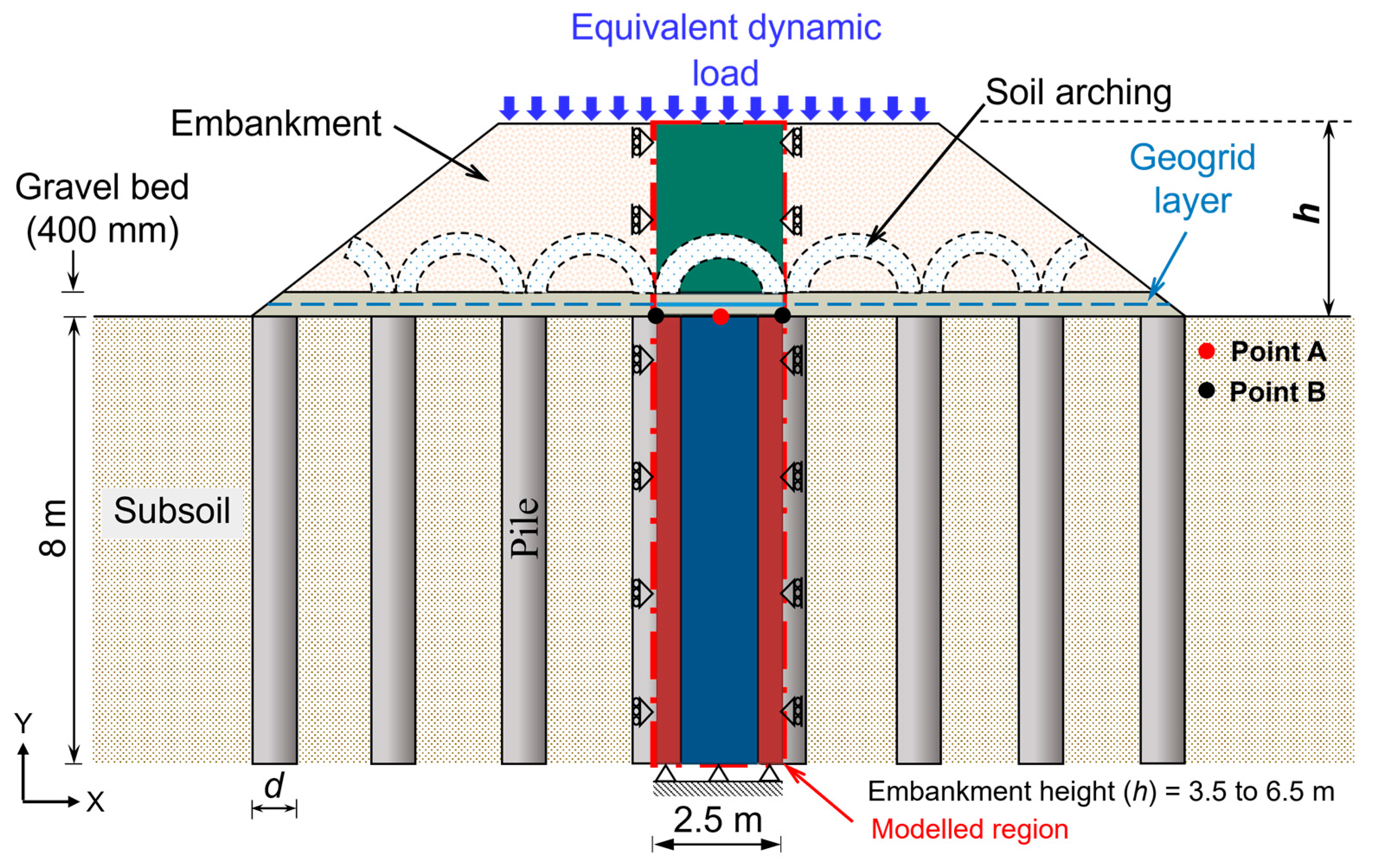
In this section, the soil arching mechanism in a basal reinforced embankment supported by pile foundations is evaluated under the two-dimensional (2D) plane strain condition using the FE-based commercial software, ABAQUS [35]. Figure 7 shows a schematic illustration of a GRPS railway embankment, featuring the soil arching mechanism and the modelled region. As evident from Figure 7, the numerical simulation focuses on the central section of the embankment. The diameter of each pile (D) and spacing between piles (s) are set at 1 m and 2.5 m, respectively. The rigid pile length and adjacent soil depth are assumed to be 8 m. The height of the embankment (h), including a 400 mm thick gravel bed, is varied from 3.5 m to 6.5 m. Additionally, a layer of geogrid with a stiffness of 1 kN/m is inserted in the middle (i.e., 200 mm) of the gravel bed. An equivalent dynamic load is exerted on top of the embankment to simulate the load induced by a moving train along with the weight of the rail track. Further, the bottom and side boundaries of the numerical model are chosen completely and normally fixed, respectively [58]. In addition, the results are presented for points A and B. The horizontal direction (along x-axis) is considered the transverse direction.
This analysis employs 1383 eight-noded, two-dimensional, quadratic (second order) solid elements with reduced integration (CPE8R). The pile–soil interaction is simulated with ‘hard’ normal contact and a penalty-based tangential behavior, featuring a coefficient of friction set at 0.7. The FE modeling methodology begins with subjecting the subsoil to a geostatic loading to establish initial stress and a predefined void ratio. The construction stages involve the placement of a gravel bed, insertion of rigid piles, and construction of the embankment. Once the entire geometry is activated, an equivalent dynamic load representing the railway track and moving train is applied to the top of the embankment.
Further details of the FE modelling procedure, including the simplification of real dynamic train load in the form of an equivalent dynamic load, the conversion from 3D to 2D plane strain condition, material parameters, and validation, can be found in the prior work [58]. In the subsequent section, a parametric investigation is carried out to examine the impact of various embankment fill parameters, such as fill height (h), modulus (Eem), and friction angle (ϕ′) of the fill material, on the soil arching mechanism. Furthermore, the effect of a basal geogrid is also examined.
3.1.2. Results and Discussion
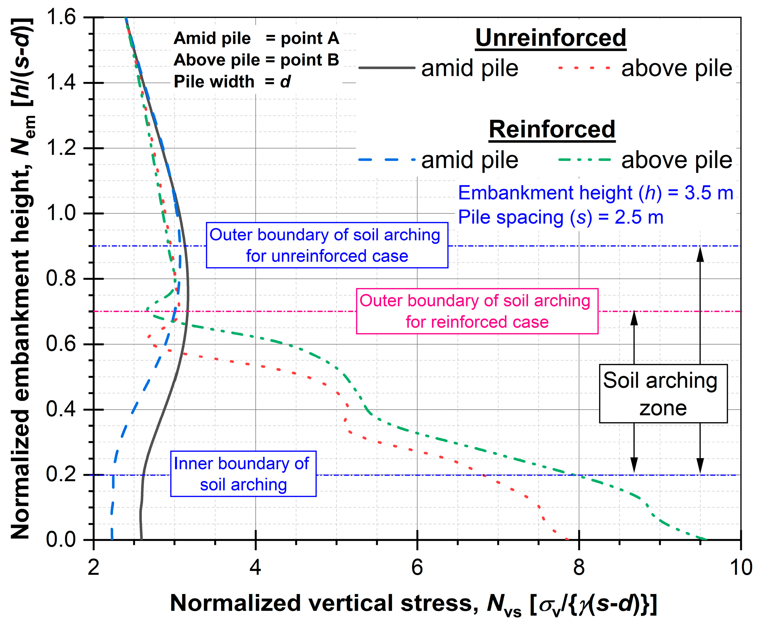
Figure 8 shows the effect of a geogrid on normalized vertical stress within the embankment fill above point A (amid pile) and point B (above pile). The height of the embankment (h) ranges from 3.5 m to 6.5 m, while the spacing between piles (s) remains constant at 3.5 m. The normalized vertical stress (Nvs) linearly increases along with the geostatic stress within the embankment fill up to a normalized embankment height (Nem) of 0.9 and 0.7 for unreinforced and reinforced cases, respectively, above both points (i.e., A and B). This normalized embankment height delimits the outer boundary of soil arching. The variation in the outer boundary is a result of differences in stress redistribution within the embankment fill, influenced by the presence of the basal geogrid layer. Beneath this embankment height, specifically above point A, the Nvs shows a reduction up to Nem = 0.2 for both cases (i.e., unreinforced and reinforced), signifying the inner boundary of soil arching. In this zone (i.e., Nem = 0.9 or 0.7 to 0.2), most of the load is redistributed through the mobilization of shear stress within the embankment fill. The Nvs at point A (Nem = 0) in the reinforced case is observed to be 10% less compared to the unreinforced case. On the contrary, the Nvs exhibits an increase beneath the outer boundary of soil arching, particularly above point B. In the reinforced case, an increase of 19% is noted in the Nvs at the embankment base compared to the unreinforced case, specifically above point B. Furthermore, below the inner boundary, the Nvs is influenced by the presence of the geogrid. The Nvs remains constant beneath the geogrid layer at point A, while it increases at point B due to the development of tension in the geogrid layer. A similar pattern of stress redistribution within the embankment fill is reported elsewhere [59].
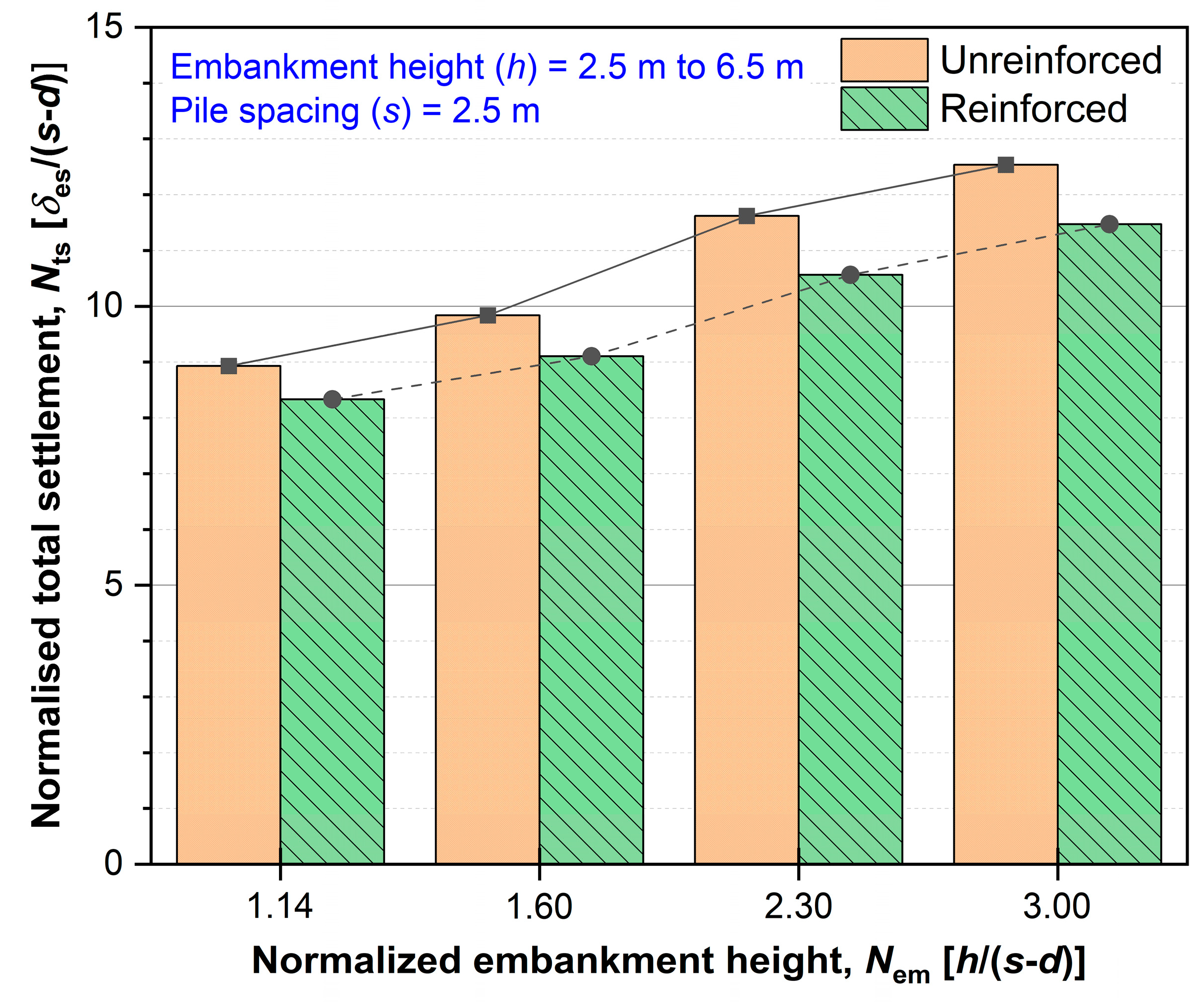
Figure 9 shows the normalized total settlement (Nts) at point A, with variations in the height of embankment (h) from 2.5 m to 6.5 m while keeping the spacing of pile (s) constant at 2.5 m. The maximum value of the Nts is considered. It is apparent that the Nts experiences an increase of up to 40% as h is raised from 2.5 to 6.5 m. This is due to an increase in the self-weight of embankment fill with a rise in embankment height. It is also apparent that the presence of a geogrid decreases the Nts, with a reduction of up to 10% observed upon incorporating basal reinforcement. Thus, Figure 8 and Figure 9 demonstrate how the basal geogrid increases the load transfer to the pile head via membrane action, resulting in a decrease in total settlement.
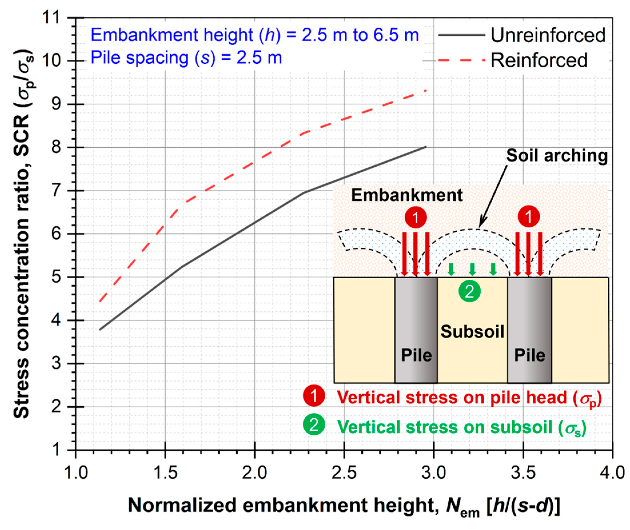
Figure 10 shows a noticeable increase in the stress concentration ratio (SCR) up to 110% when the embankment height (h) is raised from 2.5 m to 6.5 m. The SCR is determined by dividing the vertical stress on the pile head (σp) by the vertical stress on the subsoil (σs). At lower embankment heights, the shear resistance within the fill material is not fully mobilized, resulting in high stress on the subsoil. On increasing the embankment height, more shear resistance accumulates for the complete mobilization of soil arching. The SCR value exhibits an increase of up to 21% in the reinforced case in comparison to the unreinforced case. The reduction in the differential settlement at the bottom of the embankment fill (i.e., the settlement at the pile head subtracted by the settlement of the subsoil surface) contributes to the higher value of the SCR in the reinforced case in comparison to the unreinforced case. Consequently, the incorporation of a geogrid layer improves the stress transfer from the subsoil to the pile head. This observation aligns well with the results reported in Han and Gabr [50].
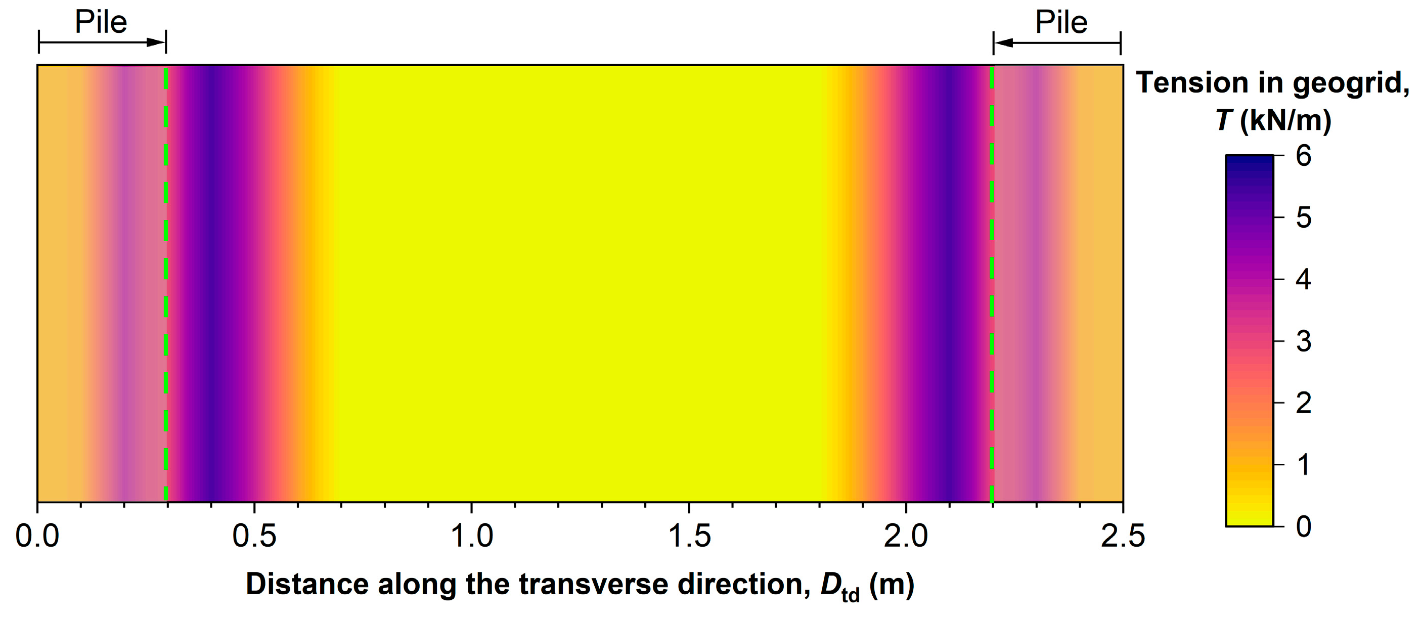
Figure 11 depicts the tension (T) distribution contour in the geogrid. It is apparent that the T is higher near the inside edges of the rigid pile. The T in the geogrid increases up to a peak value (that depends on the properties of the geogrid layer) near the inside edge of piles, and subsequently, it diminishes to zero at the mid-section of geogrid. In addition, the T slightly varies on the pile head. The higher value of T in close proximity to the head of pile reveals that the geogrid is firmly secured (full fixity) at the edge and experiences greater tension compared to the central section [60]. This observation suggests that a basal geogrid layer improves the load transfer mechanism to the rigid pile through effective tension mobilization.
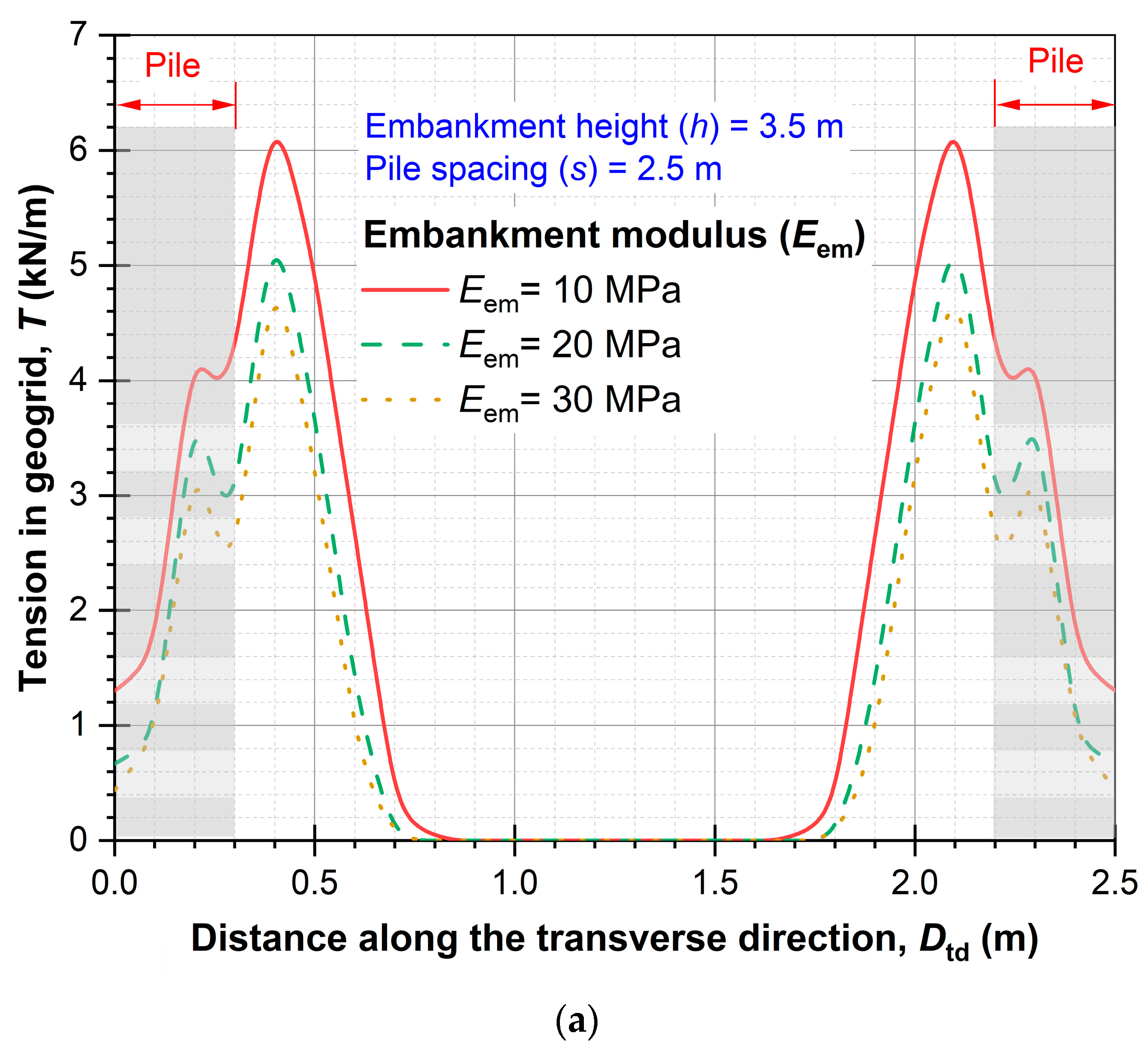
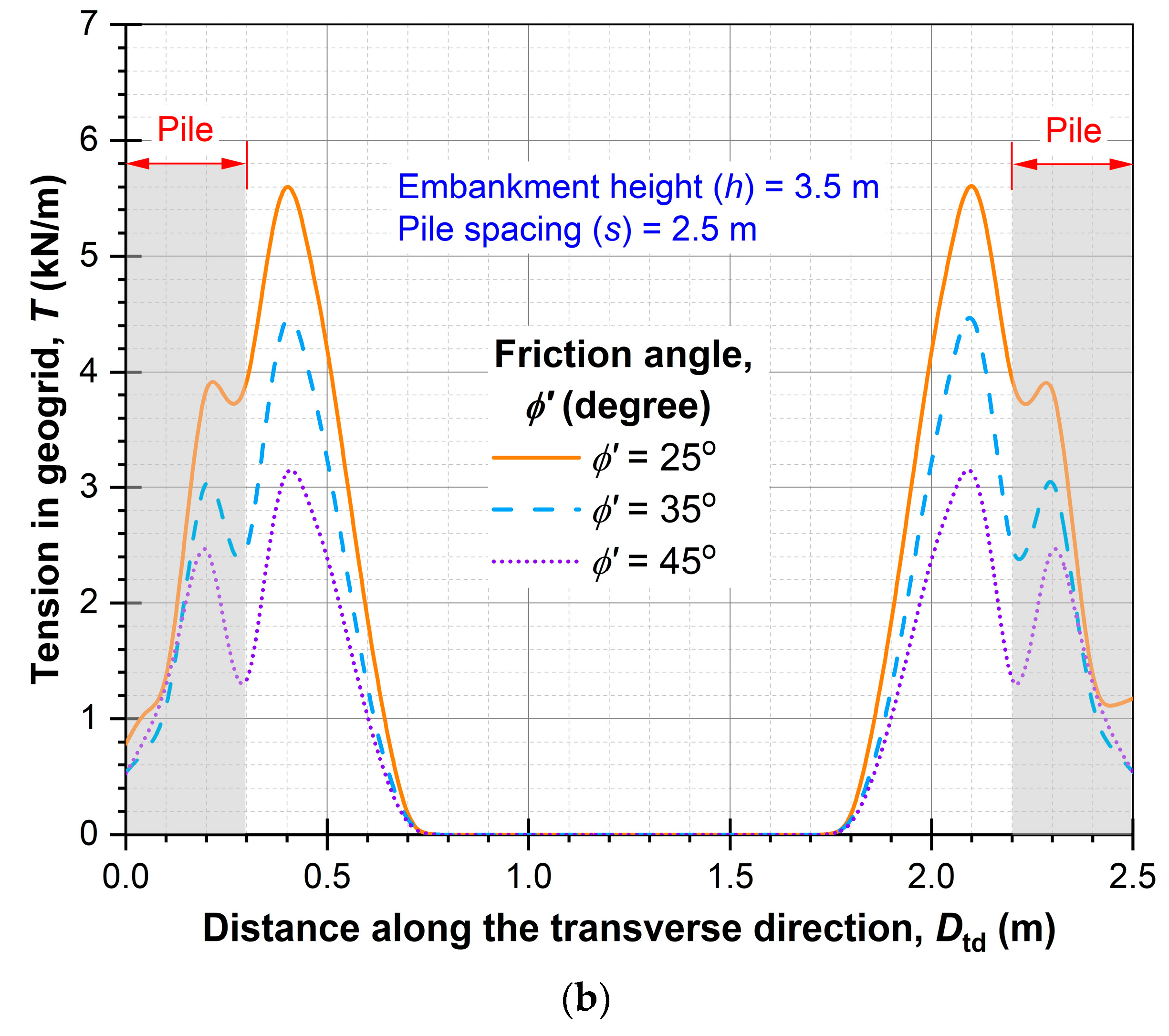
The effect of embankment fill parameters, namely, the embankment modulus (Eem) and friction angle (ϕ′), on geogrid tension (T), is illustrated in Figure 12. The tension (T) reduces by up to 35% as the Eem increases from 10 MPa to 30 MPa. Furthermore, the T diminishes by up to 54% as the ϕ′ increases from 25° to 45°. This occurs because there is a reduced settlement of the embankment fill due to the increased strength of the fill material. These results suggest that the function of a geogrid is not fully utilized if the Eem and ϕ′ are sufficiently high. Therefore, an optimal value of the Eem and ϕ′ is crucial to harness the maximum potential benefits from geogrid reinforcement.
This section examined the sustainable application of a geogrid in a GRPS railway embankment, highlighting its influence on the load transfer mechanism within the embankment fill. This section’s findings suggest that the installation of a basal geogrid layer facilitates stress transfer to the rigid pile top via the tension membrane effect, allowing an increased pile spacing and reduced number of piles. Thus, the implementation of a geogrid layer contributes to sustainability by reducing the carbon footprint associated with the construction of pile-supported railway embankments.
3.2. Use of Three-Dimensional Cellular Inclusions in Ballasted Railway Tracks
3.2.1. General
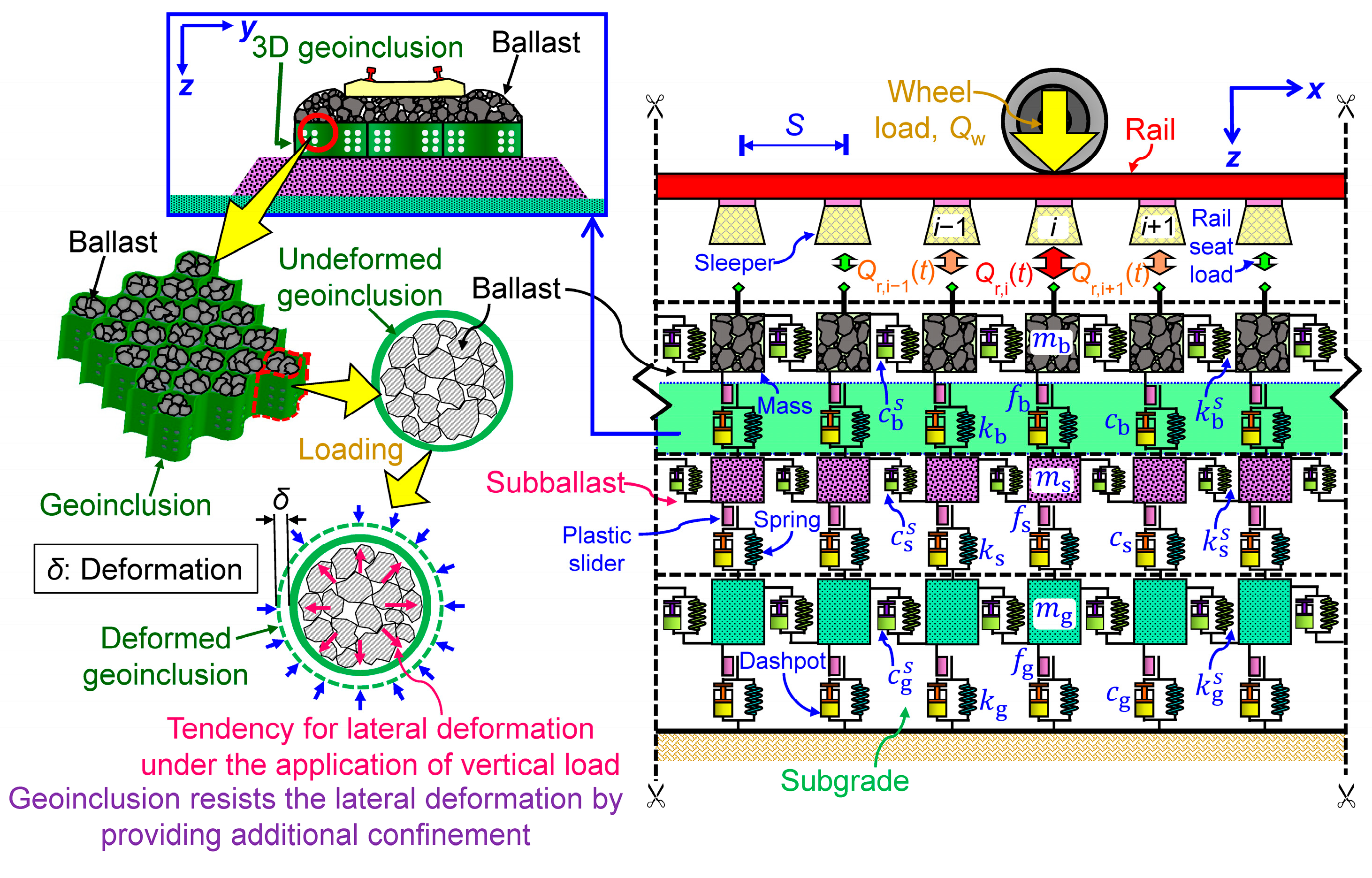
Insufficient lateral restraint or inherent confinement in the granular layers of ballasted railway tracks can result in lateral spreading, leading to a degradation of track geometry [4]. This issue can be addressed by reinforcing the granular layers using 3D cellular artificial inclusions, such as geocells. These inclusions offer both lateral restraint and additional confinement that effectively reduce the lateral and vertical deformations in the infill material [61,62,63]. Therefore, installing them in the granular layers can effectively reduce the track geometry degradation. In addition, they enhance the stiffness of the infill granular material and promote a uniform stress distribution across a large subgrade area [64]. Moreover, contingent on their installation location, these cellular inclusions can mitigate or redistribute shear stresses at interfaces between the ballast–subballast and subballast–subgrade [65]. Several in situ studies have also demonstrated the effectiveness of installing 3D cellular inclusions in ballasted railway tracks. Their installation typically curtails the vertical and lateral deformations, enhances track stiffness, reduces the subgrade stresses, and abates the rate of track geometry loss [66,67,68].
Despite its considerable potential, the utilization of 3D cellular inclusions in railway tracks remains limited because of a lack of available methods for evaluating the extent of improvement offered by these inclusions. Consequently, several researchers have explored different techniques, such as FE and discrete element (DE) analyses, to evaluate the effectiveness of using cellular inclusions in enhancing the long-term stability of railway tracks [69,70,71,72,73]. However, the DE and FE methods require substantial computational resources and typically entail a significant computational time for accurately predicting the track response, particularly when dealing with several load repetitions. The analytical approaches are relatively quicker and computationally more efficient options compared to FE or DE analyses for assessing the behavior of reinforced ballasted railway tracks. Nevertheless, these approaches are relatively scarce. The subsequent section provides insights into an innovative computational methodology that can assess the effectiveness of using these 3D cellular inclusions in ballasted railway tracks.
3.2.2. Methodology
The proposed methodology is a combination of a rheological model for railway tracks [74] and an additional confinement model for 3D cellular inclusions [75]. The additional confinement model is employed to compute the extra confining pressure offered by the geoinclusion to the infill material. The output from this model is used as an input in the rheological track model to evaluate the behavior of the reinforced railway track subjected to train-induced repetitive loading.
Figure 13 depicts the rheological model of a ballasted railway track in which a 3D cellular geoinclusion is installed at the base of the ballast layer. This model employs multiple mass elements connected using spring, damper, and plastic slider elements to represent the track substructure layers. Three substructure layers are considered in this study: ballast, subballast (also known as permeable capping), and subgrade. The train wheels are represented as point loads moving along the track in the positive x-direction, which is a simplified approach. The vertical rail seat load transferred to the substructure via the sleeper–ballast interface is computed by employing the beam on an elastic foundation approach [76].
When a wheel moves towards the track section under consideration (e.g., below ith sleeper) (loading phase), the viscoelastic elements (springs and dashpots) deform, whereas the plastic slider elements stay stationary until the stress state within the geotechnical layers meets the yield criterion and loading conditions [77]. As the wheel moves away from the considered section (unloading phase), the viscoelastic elements deform, whereas the slider elements hold the position attained at the conclusion of the loading phase. With the arrival of the next wheel, this cycle is repeated, i.e., the viscoelastic elements deform, while the sliders move once the yield criterion and loading conditions are fulfilled. Thus, the displacement of slider elements is irreversible, and it accumulates as the number of wheel passes increases. The displacement of the plastic slider elements is governed by their constitutive relationships, which are comprehensively discussed elsewhere [78].
When dynamic equilibrium conditions are applied to the rheological track model depicted in Figure 13, the following governing equation of motion is obtained:
where , and dw represent the vertical acceleration, velocity, and displacement increment vectors, respectively; C, K and M stand for damping, stiffness, and mass matrices, respectively; F denotes the force vector; and subscript i and superscript p represent the ith sleeper and the plastic component, respectively.
In order to compute the response of the reinforced railway track subjected to train-induced repetitive loading, the stiffness, damping coefficient, and vibrating mass of the substructure layers are first determined. These parameters typically require the values of density, elastic modulus, thickness, and Poisson’s ratio of the track layers [74]. Subsequently, the vertical rail seat load at every sleeper position is computed for each time step, and the stress distribution is calculated following the modified Boussinesq method [74]. At every time step, the conditions for loading and unloading for the plastic slider elements are examined, and the plastic deformations are computed once the loading conditions are satisfied (see [78]). The governing equation of motion [Equation (1)] is subsequently solved using Newmark’s numerical integration method, and the overall displacement (elastic and plastic) of the substructure layers is calculated. The extra confining pressure provided by the geoinclusion in lateral orthogonal (x and y) directions is then computed using the following equations [17]:
where Dc, Mc, and νc are the equivalent diameter, secant elastic modulus, and Poisson’s ratio of cellular geoinclusion, respectively; kc is the circumferential to radial strain ratio; and are extra confining stresses offered by the geoinclusion along x and y directions, respectively; and and represent strains in the infill along x and y directions, respectively. The stress state is subsequently updated by adding the extra confining stress to the existing stress state, and the whole procedure is repeated for the next time steps. The analysis is carried out until the specified number of load cycles (or tonnage) is reached.
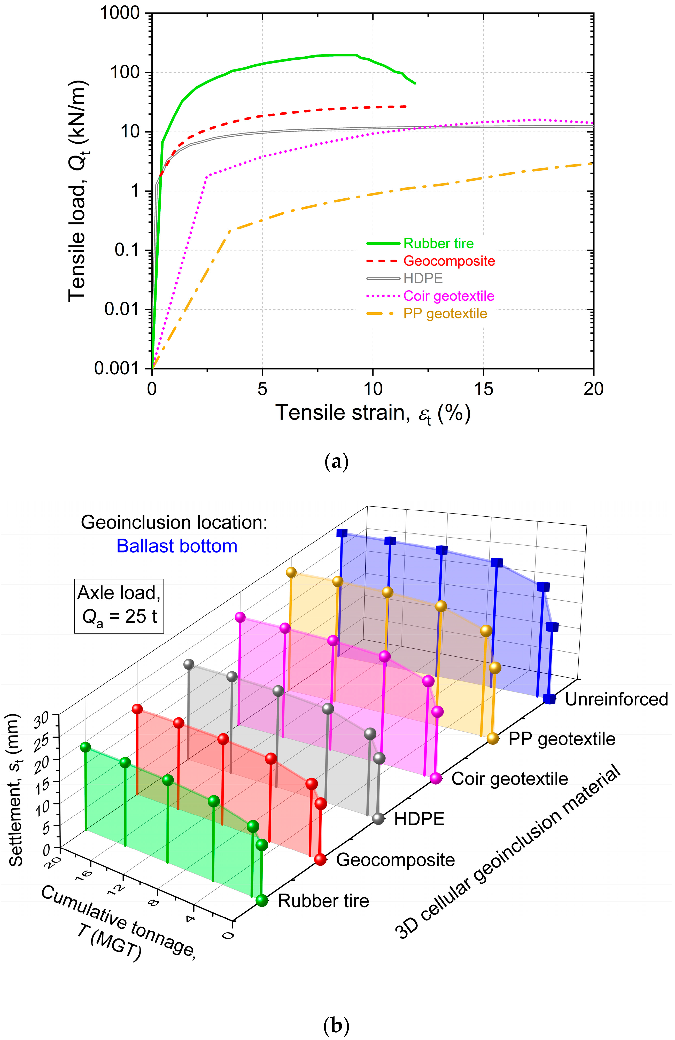
This computational approach has been validated previously by Punetha and Nimbalkar [17]. In the subsequent section, this methodology has been employed to investigate the influence of cellular geoinclusion material on the behavior of reinforced ballasted railway tracks. Five different types of material have been considered, namely, rubber tire, geocomposite, high-density polyethylene (HDPE), polypropylene (PP) geotextile, and coir geotextile. The Mc for each material depends on the magnitude of strain mobilized in the cellular geoinclusion and is obtained from the load versus strain curves (see Figure 14a). The value of νc is considered 0.3 for each geoinclusion material. The height of cellular inclusion is assumed to be 150 mm, and it is installed at the base of the ballast. The properties of the substructure layers utilized in the analysis are presented in Table 2. The axle load in the analysis is assumed to be 25 t.
3.2.3. Results and Discussion
Figure 14b illustrates the increase in settlement with tonnage in a ballasted railway track when the cellular inclusion manufactured from various materials is installed at the base of the ballast. The result of the case without geoinclusion reinforcement (unreinforced) is also provided for comparison. It is apparent from the figure that the incorporation of geoinclusion decreases the cumulative track settlement. The magnitude of reduction is contingent upon the material employed for geoinclusion fabrication. In this study, the scrap rubber tire provided the maximum reduction in settlement due to its highest stiffness among the different materials considered [17]. The least reduction in settlement is provided by the inclusion manufactured using polypropylene (PP) geotextile. This behavior is attributed to the lowest stiffness of the PP geotextile among all the materials considered in this investigation. After an accumulated tonnage of 20 MGT, the geoinclusions manufactured using rubber tire, geocomposite, HDPE, coir geotextile, and PP geotextile reduced the track settlement by 32%, 30%, 22%, 12%, and 4%, respectively, compared to the unreinforced case.
Thus, it is evident that cellular inclusions manufactured using stiffer materials offer enhanced confinement, resulting in a superior track performance compared to softer materials. Figure 14b also illustrates the capability of cellular geoinclusions to restrain the track settlement within the permissible limits. For example, considering an allowable track settlement of 25 mm after an accumulated tonnage of 20 MGT [79], the settlement in the unreinforced track surpasses the permissible threshold. In contrast, if the base of the ballast layer is reinforced with geoinclusions made from coir geotextile, geocomposite, HDPE, or rubber tire, the settlement remains within acceptable limits.
The findings of this investigation highlight that incorporating 3D cellular geoinclusions in the track enhances its performance by diminishing the vertical settlement and reducing the rate of geometry deterioration. As a result, there is a potential to reduce the frequency of routine maintenance activities, resulting in substantial cost savings and a reduction in greenhouse gas emissions. The introduction of 3D cellular inclusions into the track can also allow for a reduction in the thickness of granular substructure layers, e.g., ballast or subballast, without affecting the performance. This is particularly beneficial in situations where there is a scarcity of high-quality granular material in close proximity to the construction site, resulting in substantial cost savings and less environmental damage.
In addition, the study reveals that discarded rubber tires can significantly enhance track performance. Using scrap tires as cellular reinforcement offers an environment-friendly alternative to improve track performance, given the considerable global pollution caused by discarded tires. Hence, incorporating these tires into railway tracks could be an attractive and sustainable solution.
4. Conclusions
This article assessed the effectiveness of using scrap rubber granules and geosynthetics in augmenting the performance of railway tracks through numerical, experimental, and analytical approaches. This study leads to the following conclusions:
- The use of a scrap rubber layer reduces the vertical stress by up to 50% within the substructure of the slab track.
- Scrap rubber in its granulated form can be blended with soil to create sustainable track material, and the performance of this mixture can be further enhanced by incorporating PFA.
- The installation of a geogrid layer at the bottom of a railway embankment improves the load transfer to the pile head by up to 19%, owing to the tensioned membrane effect.
- Incorporating 3D cellular inclusions in a ballasted railway track curtails the vertical settlement by up to 32% and decreases the track geometry deterioration rate. This demonstrates the potential to reduce the frequency of maintenance operations upon the installation of 3D cellular geoinclusions, leading to substantial cost savings and a reduction in greenhouse gas emissions.
The findings from this study highlight the effectiveness of these sustainable methods in addressing the challenges posed by increased loads on railway tracks, offering valuable insights for the continuing efforts to optimize railway transportation infrastructure. The future scope of this study includes the following:
- An assessment of the field performance of railway tracks incorporating scrap rubber mixed polyurethane and geosynthetics to further advance our understanding of these sustainable approaches.
- The use of discrete element modeling (DEM) techniques to gain valuable insights into the microscale behavior of PFA-treated soil and PFA-treated soil–rubber mixtures.
- Full-scale 3D numerical modeling of the GRPS embankment to capture the influence of embankment slope on the soil arching phenomenon and the non-uniform stress distribution in the geosynthetic layers.
- A consideration of the bending of geoinclusions under the application of vertical loads in the additional confinement model to increase the accuracy of the predictions.
Author Contributions
Conceptualization, S.N.; methodology, S.N., M.A.F., N.K.M. and P.P.; software, M.A.F., N.K.M. and P.P.; validation, M.A.F., N.K.M. and P.P.; formal analysis, M.A.F., N.K.M. and P.P.; investigation, S.N., M.A.F., N.K.M. and P.P.; resources, S.N.; writing—original draft preparation, M.A.F., N.K.M. and P.P.; writing—review and editing, S.N. and N.L.; visualization, S.N., M.A.F., N.K.M. and P.P.; supervision, S.N.; project administration, S.N.; funding acquisition, S.N. All authors have read and agreed to the published version of the manuscript.
Funding
This research received no external funding.
Data Availability Statement
The data presented in this study are available on reasonable request from the corresponding author.
Acknowledgments
This research was a part of a doctoral study by M.A.F., N.K.M. and P.P. The authors thank the anonymous reviewers for their valuable suggestions and comments to improve the technical merit of this study.
Conflicts of Interest
The authors declare no conflicts of interest.
References
- United Nations. Transforming Our World: The 2030 Agenda for Sustainable Development. Available online: https://sdgs.un.org/2030agenda (accessed on 8 January 2024).
- Lawrence, M.; Bullock, R. The Role of Rail in Decarbonizing Transport in Developing Countries; World Bank: Washington, DC, USA, 2022. [Google Scholar]
- Bressi, S.; Santos, J.; Giunta, M.; Pistonesi, L.; Lo Presti, D. A comparative life-cycle assessment of asphalt mixtures for railway sub-ballast containing alternative materials. Resour. Conserv. Recycl. 2018, 137, 76–88. [Google Scholar] [CrossRef]
- Li, D.; Hyslip, J.; Sussmann, T.; Chrismer, S. Railway Geotechnics; Taylor and Francis: Boca Raton, FL, USA, 2016. [Google Scholar]
- Kiani, M.; Parry, T.; Ceney, H. Environmental life-cycle assessment of railway track beds. Proc. Inst. Civ. Eng. Eng. Sustain. 2008, 161, 135–142. [Google Scholar] [CrossRef]
- Farhan, A.H.; Dawson, A.R.; Thom, N.H. Effect of rubber incorporation on the behavior of pavement cemented mixtures under cyclic flexural loading: A preliminary study. J. Test. Eval. 2020, 48, 20170746. [Google Scholar] [CrossRef]
- Ahn, I.S.; Cheng, L.; Fox, P.J.; Wright, J.; Patenaude, S.; Fujii, B. Material properties of large-size tire derived aggregate for civil engineering applications. J. Mater. Civ. Eng. 2015, 27, 04014258. [Google Scholar] [CrossRef]
- D6270; Standard Practice for Use of Scrap Tires in Civil Engineering Applications. ASTM International: West Conshohocken, PA, USA, 2017.
- Ahn, I.S.; Cheng, L. Tire derived aggregate for retaining wall backfill under earthquake loading. Constr. Build. Mater. 2014, 57, 105–116. [Google Scholar] [CrossRef]
- Bosscher, P.J.; Edil, T.B.; Kuraoka, S. Design of highway embankments using tire chips. J. Geotech. Eng. 1997, 123, 295–304. [Google Scholar] [CrossRef]
- Kaushik, M.K.; Kumar, A.; Bansal, A. Performance assessment of gravel–tire chips mixes as drainage layer materials using real active MSW landfill leachate. Geotech. Geol. Eng. 2015, 33, 1081–1098. [Google Scholar] [CrossRef]
- Hidalgo-Signes, C.; Garzón-Roca, J.; Grima-Palop, J.M.; Insa-Franco, R. Use of rubber shreds to enhance attenuation of railway sub-ballast layers made of unbound aggregates. Mater. Constr. 2017, 67, 115. [Google Scholar] [CrossRef]
- Presti, D.L. Recycled tyre rubber modified bitumens for road asphalt mixtures: A literature review. Constr. Build. Mater. 2013, 49, 863–881. [Google Scholar] [CrossRef]
- Shalaby, A.; Khan, A.R. Temperature monitoring and compressibility measurement of a tire shred embankment: Winnipeg, Manitoba, Canada. Transp. Res. Rec. 2002, 1808, 67–75. [Google Scholar] [CrossRef]
- Koerner, R.M. Designing with Geosynthetics; Xlibris Corporation: Bloomington, IN, USA, 2012; Volume 1. [Google Scholar]
- Selig, E.T.; Waters, J.M. Track Geotechnology and Substructure Management; Thomas Telford: London, UK, 1994. [Google Scholar]
- Punetha, P.; Nimbalkar, S. Performance improvement of ballasted railway tracks using three-dimensional cellular geoinclusions. Geotext. Geomembr. 2022, 50, 1061–1082. [Google Scholar] [CrossRef]
- Liu, G.; Wang, Q.-A.; Jiao, G.; Dang, P.; Nie, G.; Liu, Z.; Sun, J. Review of Wireless RFID Strain Sensing Technology in Structural Health Monitoring. Sensors 2023, 23, 6925. [Google Scholar] [CrossRef]
- Wang, Q.-A.; Zhang, C.; Ma, Z.-G.; Jiao, G.-Y.; Jiang, X.-W.; Ni, Y.-Q.; Wang, Y.-C.; Du, Y.-T.; Qu, G.-B.; Huang, J. Towards long-transmission-distance and semi-active wireless strain sensing enabled by dual-interrogation-mode RFID technology. Struct. Control Health Monit. 2022, 29, e3069. [Google Scholar] [CrossRef]
- Wang, Q.-A.; Dai, Y.; Ma, Z.-G.; Ni, Y.-Q.; Tang, J.-Q.; Xu, X.-Q.; Wu, Z.-Y. Towards probabilistic data-driven damage detection in SHM using sparse Bayesian learning scheme. Struct. Control Health Monit. 2022, 29, e3070. [Google Scholar] [CrossRef]
- Wang, Q.-A.; Wang, H.-B.; Ma, Z.-G.; Ni, Y.-Q.; Liu, Z.-J.; Jiang, J.; Sun, R.; Zhu, H.-W. Towards high-accuracy data modelling, uncertainty quantification and correlation analysis for SHM measurements during typhoon events using an improved most likely heteroscedastic Gaussian process. Smart Struct. Syst. 2023, 32, 267–279. [Google Scholar] [CrossRef]
- Wang, Q.-A.; Dai, Y.; Ma, Z.-G.; Wang, J.-F.; Lin, J.-F.; Ni, Y.-Q.; Ren, W.-X.; Jiang, J.; Yang, X.; Yan, J.-R. Towards high-precision data modeling of SHM measurements using an improved sparse Bayesian learning scheme with strong generalization ability. Struct. Health Monit. 2024, 23, 588–604. [Google Scholar] [CrossRef]
- Farooq, M.A.; Nimbalkar, S.; Fatahi, B. Three-dimensional finite element analyses of tyre derived aggregates in ballasted and ballastless tracks. Comput. Geotech. 2021, 136, 104220. [Google Scholar] [CrossRef]
- Farooq, M.A.; Nimbalkar, S. Monotonic and cyclic triaxial testing of untreated and polyurethane-treated soil and soil–rubber mixtures. Acta Geotech. 2023. [Google Scholar] [CrossRef]
- Meles, D.; Chan, D.; Yi, Y.; Bayat, A. Finite-Element Analysis of Highway Embankment Made from Tire-Derived Aggregate. J. Mater. Civ. Eng. 2016, 28, 04015100. [Google Scholar] [CrossRef]
- Cho, S.D.; Kim, J.M.; Kim, J.H.; Lee, K.W. Utilization of waste tires to reduce railroad vibration. Mater. Sci. Forum 2007, 544, 637–640. [Google Scholar] [CrossRef]
- Wolfe, S.; Humphrey, D. Vibration attenuation of tire shreds. In Proceedings of the Rail Transit Conference, St Louis, MI, USA, 10–15 June 2000. [Google Scholar]
- D’Andrea, A.; Loprencipe, G.; Xhixha, E. Vibration induced by rail traffic: Evaluation of attenuation properties in a bituminous sub-ballast layer. Procedia Soc. Behav. Sci. 2012, 53, 245–255. [Google Scholar] [CrossRef]
- Zoccali, P.; Cantisani, G.; Loprencipe, G. Ground-vibrations induced by trains: Filled trenches mitigation capacity and length influence. Constr. Build. Mater. 2015, 74, 1–8. [Google Scholar] [CrossRef]
- Esmaeili, M.; Siahkouhi, M. Tire-derived aggregate layer performance in railway bridges as a novel impact absorber: Numerical and field study. Struct. Control Health Monit. 2019, 26, e2444. [Google Scholar] [CrossRef]
- Esmaeili, M.; Ataei, S.; Siahkouhi, M. A case study of dynamic behaviour of short span concrete slab bridge reinforced by tire-derived aggregates as sub-ballast. Int. J. Rail Transp. 2020, 8, 80–98. [Google Scholar] [CrossRef]
- Fathali, M.; Nejad, F.M.; Esmaeili, M. Influence of tire-derived aggregates on the properties of railway ballast material. J. Mater. Civ. Eng. 2017, 29, 04016177. [Google Scholar] [CrossRef]
- Sol-Sánchez, M.; Thom, N.H.; Moreno-Navarro, F.; Rubio-Gámez, M.C.; Airey, G.D. A study into the use of crumb rubber in railway ballast. Constr. Build. Mater. 2015, 75, 19–24. [Google Scholar] [CrossRef]
- Esmaeili, M.; Aela, P.; Hosseini, A. Experimental assessment of cyclic behavior of sand-fouled ballast mixed with tire derived aggregates. Soil Dyn. Earthq. Eng. 2017, 98, 1–11. [Google Scholar] [CrossRef]
- Dassault Systèmes. Abaqus; Dassault Systèmes Simulia Corp: Providence, RI, USA, 2018. [Google Scholar]
- Čebašek, T.M.; Esen, A.F.; Woodward, P.K.; Laghrouche, O.; Connolly, D.P. Full scale laboratory testing of ballast and concrete slab tracks under phased cyclic loading. Transp. Geotech. 2018, 17, 33–40. [Google Scholar] [CrossRef]
- Hall, L. Simulations and analyses of train-induced ground vibrations in finite element models. Soil Dyn. Earthq. Eng. 2003, 23, 403–413. [Google Scholar] [CrossRef]
- Dash, S.K.; Majee, A. Geogrid reinforcement for stiffness improvement of railway track formation over clay subgrade. Int. J. Geomech. 2021, 21, 04021163. [Google Scholar] [CrossRef]
- Zhang, J.; Yang, N.; Chen, X.; Hu, H.; Wang, X.; Zhang, J. Investigation of the static and dynamic characteristics of TDA-subballast mixtures. Transp. Geotech. 2022, 32, 100676. [Google Scholar] [CrossRef]
- Li, N.; Ma, B.; Wang, H.; Tang, J.; Wang, X.; Shao, Z. Influence of loading frequency on mechanical properties of unbound granular materials via repeated load tests. Constr. Build. Mater. 2021, 301, 124098. [Google Scholar] [CrossRef]
- D2487; Standard Practice for Classification of Soils for Engineering Purposes (Unified Soil Classification System). ASTM International: West Conshohocken, PA, USA, 2017.
- Farooq, M.A.; Nimbalkar, S. Static and cyclic performance of polyurethane foam adhesive bound soil–rubber mixtures under drained conditions. Acta Geotech. 2023. [Google Scholar] [CrossRef]
- Farooq, M.A.; Nimbalkar, S. Laboratory and numerical analyses on polyurethane-scrap rubber reinforced base layer. Can. Geotech. J. 2024. [Google Scholar] [CrossRef]
- Xiao, Y.; Liu, H.; Desai, C.S. New method for improvement of rockfill material with polyurethane foam adhesive. J. Geotech. Geoenviron. Eng. 2015, 141, 02814003. [Google Scholar] [CrossRef]
- Wang, H.-L.; Chen, R.-P. Estimating Static and Dynamic Stresses in Geosynthetic-Reinforced Pile-Supported Track-Bed under Train Moving Loads. J. Geotech. Geoenviron. Eng. 2019, 145, 04019029. [Google Scholar] [CrossRef]
- King, D.J.; Bouazza, A.; Gniel, J.R.; Rowe, R.K.; Bui, H.H. Load-transfer platform behaviour in embankments supported on semi-rigid columns: Implications of the ground reaction curve. Can. Geotech. J. 2017, 54, 1158–1175. [Google Scholar] [CrossRef]
- Briançon, L.; Simon, B. Pile-supported embankment over soft soil for a high-speed line. Geosynth. Int. 2017, 24, 293–305. [Google Scholar] [CrossRef]
- Almeida, M.S.S.; Ehrlich, M.; Spotti, A.P.; Marques, M.E.S. Embankment supported on piles with biaxial geogrids. Proc. Inst. Civ. Eng. Geotech. Eng. 2007, 160, 185–192. [Google Scholar] [CrossRef]
- Esen, A.F.; Woodward, P.K.; Laghrouche, O.; Connolly, D.P. Long-Term Performance Assessment of a Geosynthetic-Reinforced Railway Substructure. Sustainability 2023, 15, 9364. [Google Scholar] [CrossRef]
- Han, J.; Gabr, M.A. Numerical Analysis of Geosynthetic-Reinforced and Pile-Supported Earth Platforms over Soft Soil. J. Geotech. Geoenviron. Eng. 2002, 128, 44–53. [Google Scholar] [CrossRef]
- Arulrajah, A.; Abdullah, A.; Bo, M.W.; Leong, M. Geosynthetic applications in high-speed railways: A case study. Proc. Inst. Civ. Eng Ground Improv. 2015, 168, 3–13. [Google Scholar] [CrossRef]
- Wang, H.-L.; Chen, R.-P.; Liu, Q.-W.; Kang, X. Investigation on geogrid reinforcement and pile efficacy in geosynthetic-reinforced pile-supported track-bed. Geotext. Geomembr. 2019, 47, 755–766. [Google Scholar] [CrossRef]
- Terzaghi, K. Theoretical Soil Mechanics; John Wiley and Sons: New York, NY, USA, 1943. [Google Scholar]
- Liu, H.L.; Ng, C.W.W.; Fei, K. Performance of a Geogrid-Reinforced and Pile-Supported Highway Embankment over Soft Clay: Case Study. J. Geotech. Geoenviron. Eng. 2007, 133, 1483–1493. [Google Scholar] [CrossRef]
- Nunez, M.A.; Briançon, L.; Dias, D. Analyses of a pile-supported embankment over soft clay: Full-scale experiment, analytical and numerical approaches. Eng. Geol. 2013, 153, 53–67. [Google Scholar] [CrossRef]
- Rowe, R.K.; Liu, K.-W. Three-dimensional finite element modelling of a full-scale geosynthetic-reinforced, pile-supported embankment. Can. Geotech. J. 2015, 52, 2041–2054. [Google Scholar] [CrossRef]
- Wang, K.; Zhuang, Y.; Liu, H.; Xiao, H. Multilayered low-strength geogrid-reinforced piled embankment. Geotech. Res. 2018, 5, 231–246. [Google Scholar] [CrossRef]
- Meena, N.K.; Nimbalkar, S.; Fatahi, B.; Yang, G. Effects of soil arching on behavior of pile-supported railway embankment: 2D FEM approach. Comput. Geotech. 2020, 123, 103601. [Google Scholar] [CrossRef]
- Lee, T.; van Eekelen, S.J.M.; Jung, Y.-H. Numerical verification of the Concentric Arches model for geosynthetic-reinforced pile-supported embankments: Applicability and limitations. Can. Geotech. J. 2021, 58, 441–454. [Google Scholar] [CrossRef]
- Tran, Q.A.; Villard, P.; Dias, D. Geosynthetic reinforced piled embankment modeling using discrete and continuum approaches. Geotext. Geomembr. 2021, 49, 243–256. [Google Scholar] [CrossRef]
- Cowland, J.; Wong, S. Performance of a road embankment on soft clay supported on a geocell mattress foundation. Geotext. Geomembr. 1993, 12, 687–705. [Google Scholar] [CrossRef]
- Song, F.; Liu, H.; Yang, B.; Zhao, J. Large-scale triaxial compression tests of geocell-reinforced sand. Geosynth. Int. 2019, 26, 388–395. [Google Scholar] [CrossRef]
- Chrismer, S. Test of Geoweb to Improve Track Stability over Soft Subgrade; TD 97-045; Association of American Railroads: Washington, DC, USA, 1997. [Google Scholar]
- Zhou, H.; Wen, X. Model studies on geogrid-or geocell-reinforced sand cushion on soft soil. Geotext. Geomembr. 2008, 26, 231–238. [Google Scholar] [CrossRef]
- Giroud, J.P.; Han, J. Design method for geogrid-reinforced unpaved roads. I. Development of design method. J. Geotech. Geoenviron. Eng. 2004, 130, 775–786. [Google Scholar] [CrossRef]
- Raymond, G.P. Failure and reconstruction of a gantry crane ballasted track. Can. Geotech. J. 2001, 38, 507–529. [Google Scholar] [CrossRef]
- Zarembski, A.M.; Palese, J.; Hartsough, C.M.; Ling, H.I.; Thompson, H. Application of geocell track substructure support system to correct surface degradation problems under high-speed passenger railroad operations. Transp. Infrastruct. Geotech. 2017, 4, 106–125. [Google Scholar] [CrossRef]
- Kaewunruen, S.; Remennikov, A.M.; Nguyen, P.; Aikawa, A. Field performance to mitigate impact vibration at railway bridge ends using soft baseplates. In Proceedings of the 11th World Congress on Railway Research, Milan, Italy, 29 May–2 June 2016; pp. 1–10. [Google Scholar]
- Leshchinsky, B.; Ling, H. Numerical modeling of behavior of railway ballasted structure with geocell confinement. Geotext. Geomembr. 2013, 36, 33–43. [Google Scholar] [CrossRef]
- Punetha, P.; Nimbalkar, S. Numerical investigation on dynamic behaviour of critical zones in railway tracks under moving train loads. Transp. Geotech. 2023, 41, 101009. [Google Scholar] [CrossRef]
- Liu, Y.; Deng, A.; Jaksa, M. Three-dimensional modeling of geocell-reinforced straight and curved ballast embankments. Comput. Geotech. 2018, 102, 53–65. [Google Scholar] [CrossRef]
- Banerjee, L.; Chawla, S.; Dash, S.K. Application of geocell reinforced coal mine overburden waste as subballast in railway tracks on weak subgrade. Constr. Build. Mater. 2020, 265, 120774. [Google Scholar] [CrossRef]
- Liu, Y.; Deng, A.; Jaksa, M. Three-Dimensional Discrete-Element Modeling of Geocell-Reinforced Ballast Considering Breakage. Int. J. Geomech. 2020, 20, 04020032. [Google Scholar] [CrossRef]
- Punetha, P.; Nimbalkar, S.; Khabbaz, H. Simplified geotechnical rheological model for simulating viscoelasto-plastic response of ballasted railway substructure. Int. J. Numer. Anal. Methods Geomech. 2021, 45, 2019–2047. [Google Scholar] [CrossRef]
- Punetha, P.; Nimbalkar, S.; Khabbaz, H. Evaluation of additional confinement for three-dimensional geoinclusions under general stress state. Can. Geotech. J. 2020, 57, 453–461. [Google Scholar] [CrossRef]
- Doyle, N.F. Railway Track Design: A Review of Current Practice; BHP Melbourne Research Laboratories, Australian Government Publishing Service: Canberra, Australia, 1980. [Google Scholar]
- Simo, J.C.; Hughes, T.J.R. Computational Inelasticity; Springer: New York, NY, USA, 1998. [Google Scholar]
- Punetha, P.; Nimbalkar, S. Geotechnical rheological modeling of ballasted railway tracks considering the effect of principal stress rotation. Can. Geotech. J. 2022, 59, 1793–1818. [Google Scholar] [CrossRef]
- Sayeed, M.A.; Shahin, M.A. Design of ballasted railway track foundations using numerical modelling. Part II: Applications. Can. Geotech. J. 2018, 55, 369–396. [Google Scholar] [CrossRef]
Figure 1.
3D FE model of slab track.

Figure 2.
Variation in vertical stress with depth at various train speed: (a) without rubber layer; (b) with 25 mm rubber layer beneath the base layer (reproduced from [23], with permission from Elsevier); (c) comparison of cumulative settlement between slab tracks with and without a rubber layer (data sourced from [23]).

Figure 3.
Particle size distribution of soil and rubber adopted in this study (data sourced from [24,38,39,40,42]).

Figure 4.
Schematic diagram of (a) direct simple shear device; (b) advanced dynamic triaxial device.
Figure 4.
Schematic diagram of (a) direct simple shear device; (b) advanced dynamic triaxial device.

Figure 5.
3D ribbon plots showing the variation in cohesion and ultimate friction angle of (a) soil at varying PFA content; (b) untreated and treated soil at different rubber contents (data sourced from [42]).
Figure 5.
3D ribbon plots showing the variation in cohesion and ultimate friction angle of (a) soil at varying PFA content; (b) untreated and treated soil at different rubber contents (data sourced from [42]).

Figure 6.
Variation in (a) residual vertical strain; (b) volumetric strain; (c) damping ratio; (d) resilient modulus with number of load cycles for four different mixtures (data sourced from [24]).
Figure 6.
Variation in (a) residual vertical strain; (b) volumetric strain; (c) damping ratio; (d) resilient modulus with number of load cycles for four different mixtures (data sourced from [24]).

Figure 7.
Schematic diagram of a GRPS railway embankment with soil arching mechanism (modified from [58]).
Figure 7.
Schematic diagram of a GRPS railway embankment with soil arching mechanism (modified from [58]).

Figure 8.
Influence of geogrid on normalized vertical stress within embankment fill.

Figure 9.
Effect of geogrid on total settlement of embankment base.

Figure 10.
Influence of geogrid on stress concentration ratio.

Figure 11.
Tension distribution in geogrid.

Figure 12.
Influence of (a) elastic modulus; (b) friction angle of embankment fill on tension in geogrid.
Figure 12.
Influence of (a) elastic modulus; (b) friction angle of embankment fill on tension in geogrid.


Figure 13.
Rheological model of ballasted railway track in which cellular inclusion is installed at the ballast bottom.
Figure 13.
Rheological model of ballasted railway track in which cellular inclusion is installed at the ballast bottom.

Figure 14.
(a) Tensile load–tensile strain relationships for different geoinclusion materials (modified from [75]); (b) variation in settlement with cumulative tonnage for unreinforced and geoinclusion-reinforced ballasted railway track (data sourced from [17]).


| Properties | Rail 1 | Concrete Slab 1 | CAM 1 | Base Layer 1 | Subbase Layer 1 | Subgrade 1 |
|---|---|---|---|---|---|---|
| Constitutive model | LE | LE | LE | LE | DP | MC |
| (kg/m3) | 7830 | 2700 | 2250 | 2700 | 2220 | 2220 |
| Elastic modulus, E (MPa) | 210,000 | 20,000 | 27,000 | 7500 | 400 | 400 |
| Poisson’s ratio, v | 0.3 | 0.167 | 0.167 | 0.167 | 0.25 | 0.25 |
| Friction angle, φ | - | - | - | - | 35 | 35 |
| Dilation angle, | - | - | - | - | 2 | 2 |
| Damping ratio, ζ | - | - | - | - | 0.04 2 | 0.04 2 |
Disclaimer/Publisher’s Note: The statements, opinions and data contained in all publications are solely those of the individual author(s) and contributor(s) and not of MDPI and/or the editor(s). MDPI and/or the editor(s) disclaim responsibility for any injury to people or property resulting from any ideas, methods, instructions or products referred to in the content. |
© 2024 by the authors. Licensee MDPI, Basel, Switzerland. This article is an open access article distributed under the terms and conditions of the Creative Commons Attribution (CC BY) license (https://creativecommons.org/licenses/by/4.0/).
Share and Cite
MDPI and ACS Style
Farooq, M.A.; Meena, N.K.; Punetha, P.; Nimbalkar, S.; Lam, N. Experimental and Computational Analyses of Sustainable Approaches in Railways. Infrastructures 2024, 9, 53. https://doi.org/10.3390/infrastructures9030053
AMA Style
Farooq MA, Meena NK, Punetha P, Nimbalkar S, Lam N. Experimental and Computational Analyses of Sustainable Approaches in Railways. Infrastructures. 2024; 9(3):53. https://doi.org/10.3390/infrastructures9030053
Chicago/Turabian StyleFarooq, Mohammad Adnan, Naveen Kumar Meena, Piyush Punetha, Sanjay Nimbalkar, and Nelson Lam. 2024. "Experimental and Computational Analyses of Sustainable Approaches in Railways" Infrastructures 9, no. 3: 53. https://doi.org/10.3390/infrastructures9030053