
Alternative Brain Slice-on-a-Chip for Organotypic Culture and Effective Fluorescence Injection Testing

 ,
,  ,
,  and
and 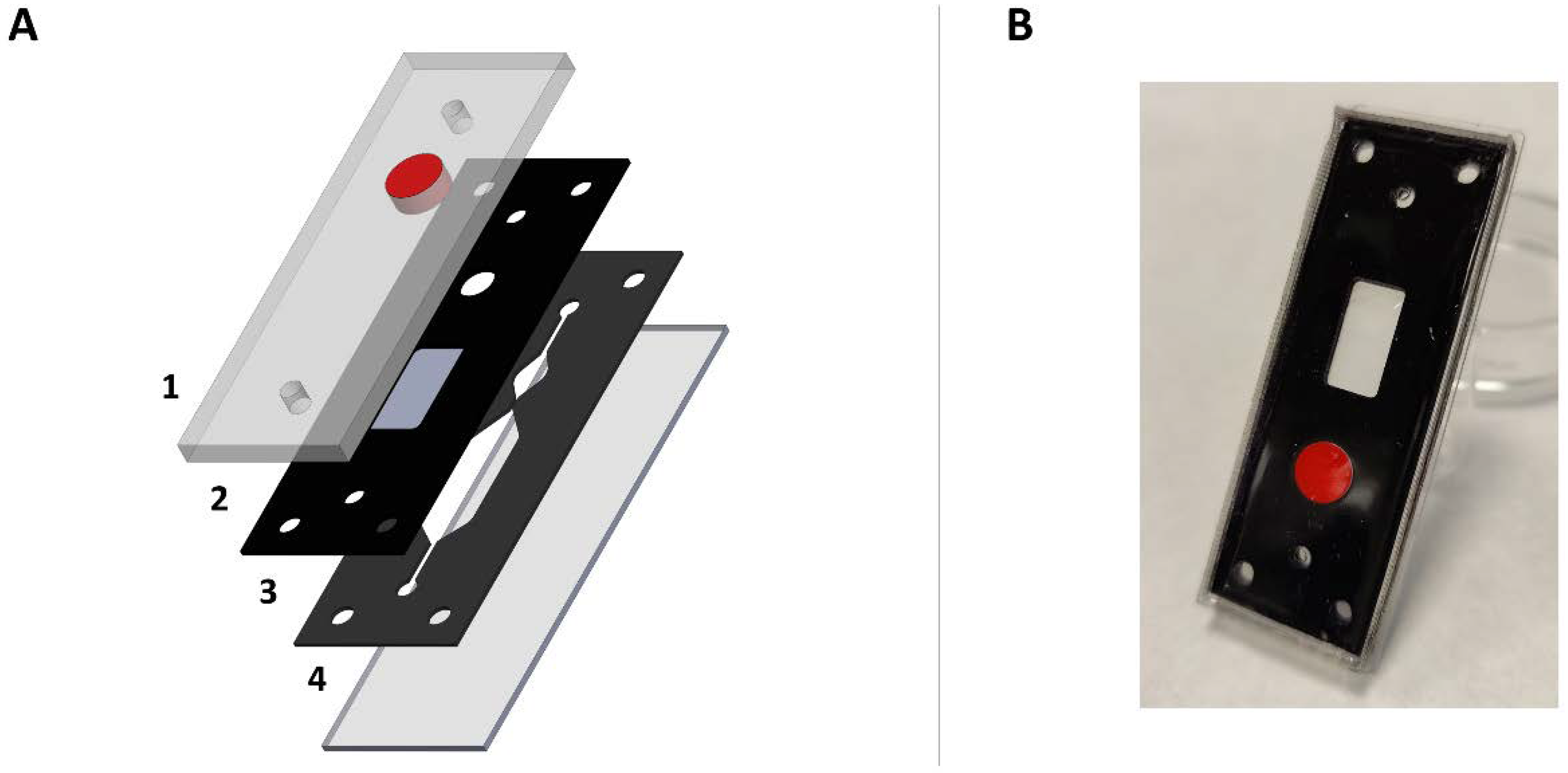
Abstract
:1. Introduction
2. Results
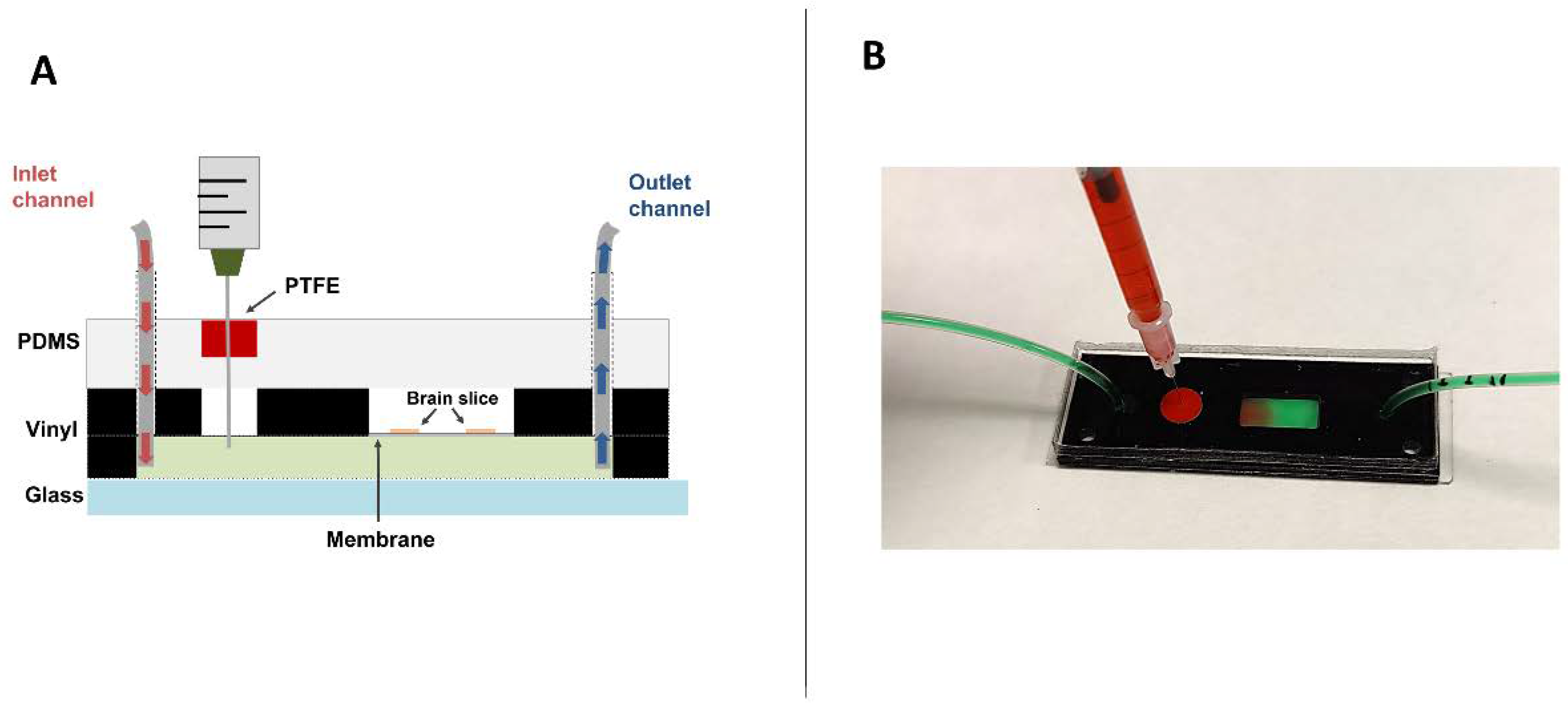
2.1. Chip Development and Injection System Implementation
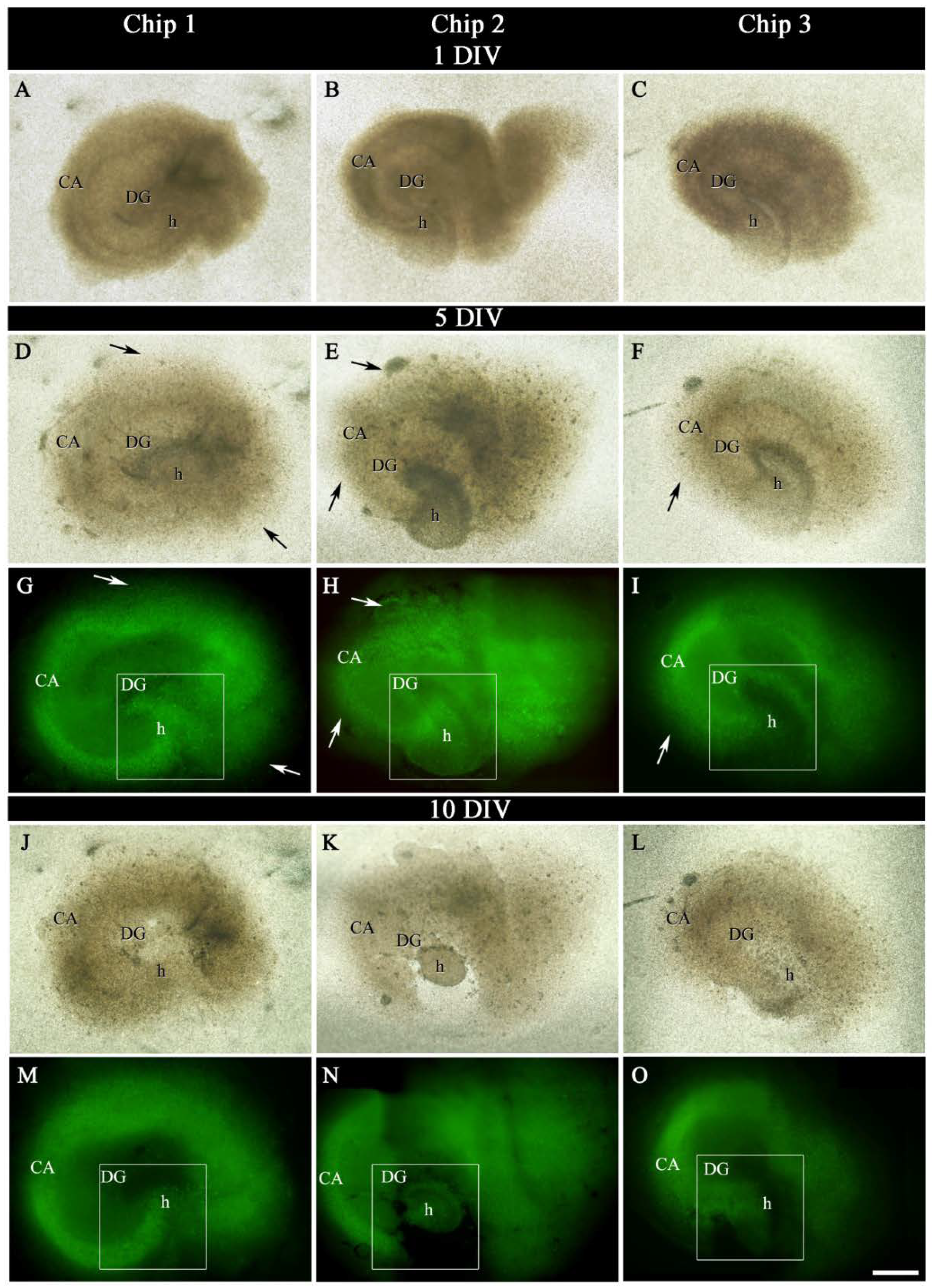
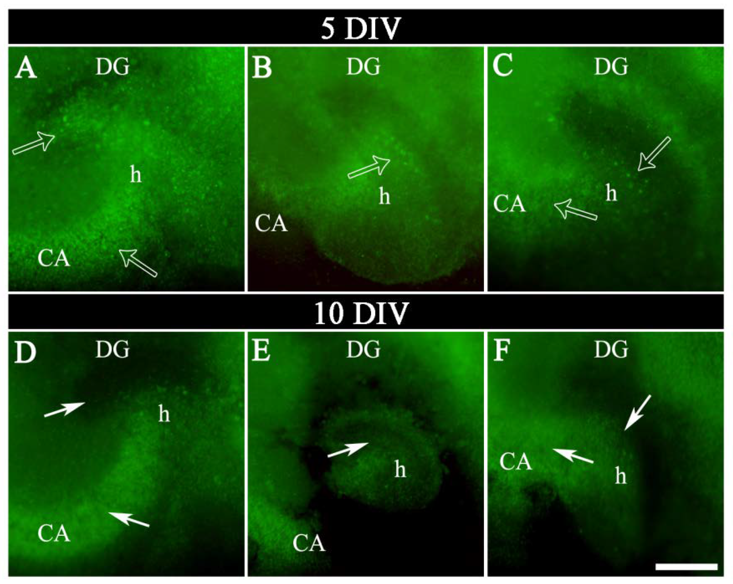
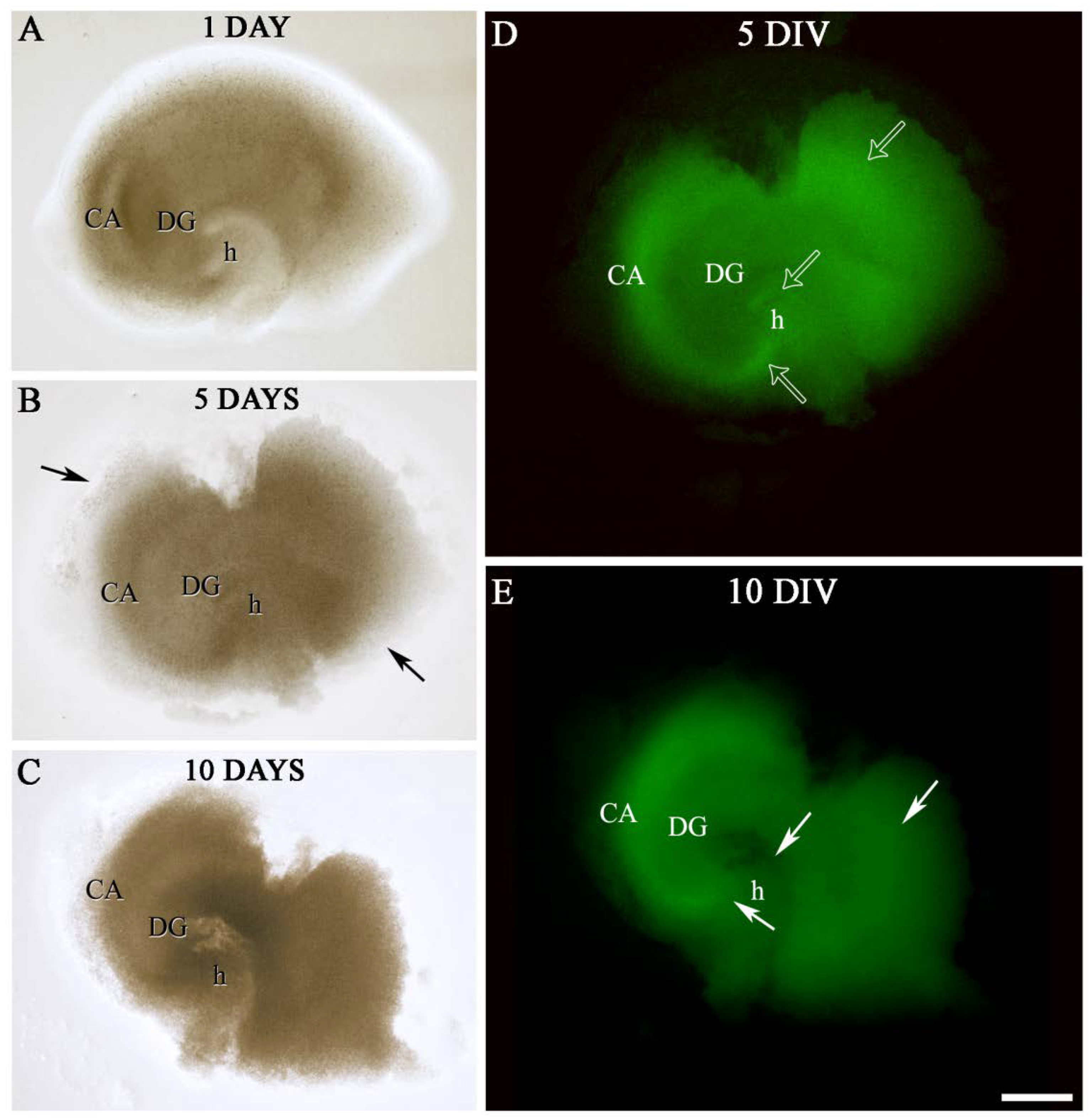
2.2. Labeling of OGB in Hippocampal Sections
3. Discussion
4. Materials and Methods
4.1. Design of the Brain Slice-on-a-Chip Device
4.2. Brain Slice-on-a-Chip Fabrication
4.3. Hippocampal Slices MICE
4.4. Slice Preparation
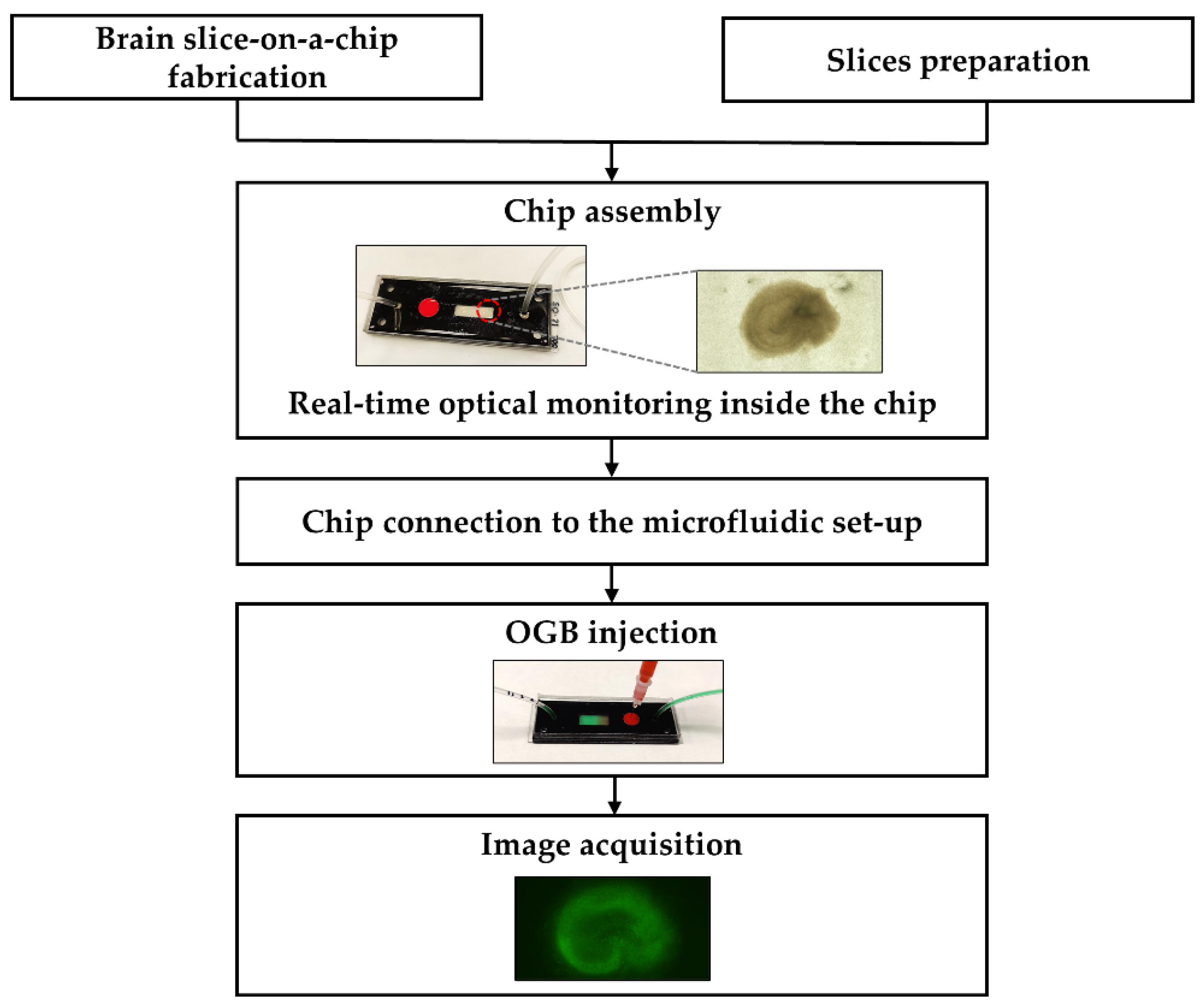
4.5. Procedure of the Brain Slice-on-a-Chip Set-Up
4.6. Organotypic Hippocampal Slice Culture
4.7. Dye Injection and Image Acquisition
5. Conclusions
Author Contributions
Funding
Institutional Review Board Statement
Informed Consent Statement
Data Availability Statement
Acknowledgments
Conflicts of Interest
Abbreviations
| DIV | day in vitro |
| CA | cornu Ammonis subfield |
| DG | dentate gyrus |
| DMSO | dimethylsulphoxide |
| OGB | Oregon Green Bapta |
| OHSC | organotypic hippocampal slice culture |
| PDMS | polydimethylsiloxane |
| PTFE | polytetrafluoroethylene |
References
- Humpel, C. Neuroscience Forefront Review Organotypic Brain Slice Cultures: A Review. Neuroscience 2015, 305, 86–98. [Google Scholar] [CrossRef] [PubMed] [Green Version]
- Pas, S.P. The Rise of Three-Dimensional Human Brain Cultures. Nature 2018, 553, 437–445. [Google Scholar]
- Croft, C.L.; Futch, H.S.; Moore, B.D.; Golde, T.E. Organotypic Brain Slice Cultures to Model Neurodegenerative Proteinopathies. Mol. Neurodegener. 2019, 14, 1–11. [Google Scholar] [CrossRef] [PubMed] [Green Version]
- Raineteau, O.; Rietschin, L.; Gradwohl, G.; Guillemot, F.; Gähwiler, B.H. Neurogenesis in Hippocampal Slice Cultures. Mol. Cell. Neurosci. 2004, 26, 241–250. [Google Scholar] [CrossRef] [PubMed]
- Reshetnikov, V.; Ryabushkina, Y.; Kovner, A.; Lepeshko, A.; Bondar, N. Repeated and Single Maternal Separation Specifically Alter Microglial Morphology in the Prefrontal Cortex and Neurogenesis in the Hippocampus of 15-Day-Old Male Mice. NeuroReport 2020, 31, 1256–1264. [Google Scholar] [CrossRef]
- Nikonenko, I.; Toni, N.; Moosmayer, M.; Shigeri, Y.; Muller, D.; Sargent Jones, L. Integrins Are Involved in Synaptogenesis, Cell Spreading, and Adhesion in the Postnatal Brain. Brain Res. Dev. Brain Res. 2003, 140, 185–194. [Google Scholar] [CrossRef]
- Lee, K.H.; Lee, H.; Yang, C.H.; Ko, J.S.; Park, C.H.; Woo, R.S.; Kim, J.Y.; Sun, W.; Kim, J.H.; Ho, W.K.; et al. Bidirectional Signaling of Neuregulin-2 Mediates Formation of GABAergic Synapses and Maturation of Glutamatergic Synapses in Newborn Granule Cells of Postnatal Hippocampus. J. Neurosci. 2015, 35, 16479–16493. [Google Scholar] [CrossRef] [PubMed] [Green Version]
- Kim, J.; Byun, J.-W.; Choi, I.; Kim, B.; Jeong, H.-K.; Jou, I.; Joe, E. PINK1 Deficiency Enhances Inflammatory Cytokine Release from Acutely Prepared Brain Slices. Exp. Neurobiol. 2013, 22, 38–44. [Google Scholar] [CrossRef] [Green Version]
- Pandamooz, S.; Salehi, M.S.; Zibaii, M.I.; Safari, A.; Nabiuni, M.; Ahmadiani, A.; Dargahi, L. Modeling Traumatic Injury in Organotypic Spinal Cord Slice Culture Obtained from Adult Rat. Tissue Cell 2019, 56, 90–97. [Google Scholar] [CrossRef]
- Gähwiler, B.H. Organotypic Monolayer Cultures of Nervous Tissue. J. Neurosci. Methods 1981, 4, 329–342. [Google Scholar] [CrossRef]
- Victorov, I.V.; Lyjin, A.A.; Aleksandrova, O.P. A Modified Roller Method for Organotypic Brain Cultures: Free-Floating Slices of Postnatal Rat Hippocampus. Brain Res. Protoc. 2001, 7, 30–37. [Google Scholar] [CrossRef]
- de Simoni, A.; Yu, L.M.Y. Preparation of Organotypic Hippocampal Slice Cultures: Interface Method. Nat. Protoc. 2006, 1, 1439–1445. [Google Scholar] [CrossRef]
- Stoppini, L.; Buchs, P.A.; Muller, D. A Simple Method for Organotypic Cultures of Nervous Tissue. J. Neurosci. Methods 1991, 37, 173–182. [Google Scholar] [CrossRef]
- Hájos, N.; Ellender, T.J.; Zemankovics, R.; Mann, E.O.; Exley, R.; Cragg, S.J.; Freund, T.F.; Paulsen, O. Maintaining Network Activity in Submerged Hippocampal Slices: Importance of Oxygen Supply. Eur. J. Neurosci. 2009, 29, 319–327. [Google Scholar] [CrossRef] [Green Version]
- Lu, R.X.Z.; Radisic, M. Organ-on-a-Chip Platforms for Evaluation of Environmental Nanoparticle Toxicity. Bioact. Mater. 2021, 6, 2801. [Google Scholar] [CrossRef]
- Rothbauer, M.; Rosser, J.M.; Zirath, H.; Ertl, P. Tomorrow Today: Organ-on-a-Chip Advances towards Clinically Relevant Pharmaceutical and Medical in Vitro Models. Curr. Opin. Biotechnol. 2019, 55, 81–86. [Google Scholar] [CrossRef]
- Tian, C.; Tu, Q.; Liu, W.; Wang, J. Recent Advances in Microfluidic Technologies for Organ-on-a-Chip. TrAC-Trends Anal. Chem. 2019, 117, 146–156. [Google Scholar] [CrossRef]
- Yi, L.; Wang, X.; Dhumpa, R.; Schrell, A.M.; Mukhitov, N.; Roper, M.G. Integrated Perfusion and Separation Systems for Entrainment of Insulin Secretion from Islets of Langerhans. Lab Chip 2015, 15, 823–832. [Google Scholar] [CrossRef] [Green Version]
- Shah, P.; Vedarethinam, I.; Kwasny, D.; Andresen, L.; Dimaki, M.; Skov, S.; Svendsen, W.E. Microfluidic Bioreactors for Culture of Non-Adherent Cells. Sens. Actuators B Chem. 2011, 156, 1002–1008. [Google Scholar] [CrossRef]
- Vedarethinam, I.; Avaliani, N.; Tønnesen, J.; Hansen, J.; Sabourin, D.; Dimaki, M.; Kokaia, M.; Dufva, M.; Svendsen, W.E.; Emnéus, J.; et al. Long-Term Brain Slice Culturing in a Microfluidic Platform. In Proceedings of the 15th International Conference on Miniaturized Systems for Chemistry and Life Sciences, Seattle, WA, USA, 2–6 October 2011; pp. 1560–1563. [Google Scholar]
- Hájos, N.; Mody, I. Establishing a Physiological Environment for Visualized in Vitro Brain Slice Recordings by Increasing Oxygen Supply and Modifying ACSF Content. J. Neurosci. Methods 2009, 183, 107–113. [Google Scholar] [CrossRef] [Green Version]
- Huang, Y.; Williams, J.C.; Johnson, S.M. Brain Slice on a Chip: Opportunities and Challenges of Applying Microfluidic Technology to Intact Tissues. Lab Chip 2012, 12, 2103–2117. [Google Scholar] [CrossRef] [PubMed]
- Bakmand, T.; Troels-Smith, A.R.; Dimaki, M.; Nissen, J.D.; Andersen, K.B.; Sasso, L.; Waagepetersen, H.S.; Gramsbergen, J.B.; Svendsen, W.E. Fluidic System for Long-Term in Vitro Culturing and Monitoring of Organotypic Brain Slices. Biomed. Microdevices 2015, 17, 71. [Google Scholar] [CrossRef] [PubMed]
- Queval, A.; Ghattamaneni, N.R.; Perrault, C.M.; Gill, R.; Mirzaei, M.; McKinney, R.A.; Juncker, D. Chamber and Microfluidic Probe for Microperfusion of Organotypic Brain Slices. Lab Chip 2010, 10, 326–334. [Google Scholar] [CrossRef]
- Rambani, K.; Vukasinovic, J.; Glezer, A.; Potter, S.M. Culturing Thick Brain Slices: An Interstitial 3D Microperfusion System for Enhanced Viability. J. Neurosci. Methods 2009, 180, 243–254. [Google Scholar] [CrossRef] [Green Version]
- Blake, A.J.; Pearce, T.M.; Rao, N.S.; Johnson, S.M.; Williams, J.C. Multilayer PDMS Microfluidic Chamber for Controlling Brain Slice Microenvironment. Lab Chip 2007, 7, 842–849. [Google Scholar] [CrossRef]
- Liu, J.; Pan, L.; Cheng, X.; Berdichevsky, Y. Perfused Drop Microfluidic Device for Brain Slice Culture-Based Drug Discovery. Biomed. Microdevices 2016, 18, 1–10. [Google Scholar] [CrossRef] [Green Version]
- Sun, M.; Kaplan, S.V.; Gehringer, R.C.; Limbocker, R.A.; Johnson, M.A. Localized Drug Application and Sub-Second Voltammetric Dopamine Release Measurements in a Brain Slice Perfusion Device. Anal. Chem. 2014, 86, 4151–4156. [Google Scholar] [CrossRef]
- Wilhelm, I.; Krizbai, I.A. In Vitro Models of the Blood-Brain Barrier for the Study of Drug Delivery to the Brain. Mol. Pharm. 2014, 11, 1949–1963. [Google Scholar] [CrossRef]
- Fan, Y.; Nguyen, D.T.; Akay, Y.; Xu, F.; Akay, M. Engineering a Brain Cancer Chip for High-Throughput Drug Screening. Sci. Rep. 2016, 6, 25062. [Google Scholar] [CrossRef] [Green Version]
- Park, J.; Lee, B.K.; Jeong, G.S.; Hyun, J.K.; Lee, C.J.; Lee, S.H. Three-Dimensional Brain-on-a-Chip with an Interstitial Level of Flow and Its Application as an in Vitro Model of Alzheimer’s Disease. Lab Chip 2015, 15, 141–150. [Google Scholar] [CrossRef]
- Hasan, M.N.; Radwan, A.N.; Kim, M.; Kucukal, E.; Maji, D.; Pashaei, V.; Chung, C.-Y.; Kakkar, A.; Gurkan, U.A. Emerging Micro and Nanotechnologies in Neuroscience: Devices, Fabrication Methods, and Implementation in Monitoring of Neural Activity and Drug Delivery. Technology 2019, 7, 57–83. [Google Scholar] [CrossRef]
- Gonzalez-Riano, C.; Tapia-González, S.; García, A.; Muñoz, A.; DeFelipe, J.; Barbas, C. Metabolomics and Neuroanatomical Evaluation of Post-Mortem Changes in the Hippocampus. Brain Struct. Funct. 2017, 222, 2831–2853. [Google Scholar] [CrossRef] [PubMed] [Green Version]
- Tapia-González, S.; Insausti, R.; DeFelipe, J. Differential Expression of Secretagogin Immunostaining in the Hippocampal Formation and the Entorhinal and Perirhinal Cortices of Humans, Rats, and Mice. J. Comp. Neurol. 2020, 528, 523–541. [Google Scholar] [CrossRef] [PubMed] [Green Version]
- The Mouse Brain in Stereotaxic Coordinates, Compact-3rd Edition. Available online: https://www.elsevier.com/books/the-mouse-brain-in-stereotaxic-coordinates-compact/franklin/978-0-12-374244-5 (accessed on 23 October 2021).
- Guy, Y.; Rupert, A.E.; Sandberg, M.; Weber, S.G. A Simple Method for Measuring Organotypic Tissue Slice Culture Thickness. J. Neurosci. Methods 2011, 199, 78–81. [Google Scholar] [CrossRef] [Green Version]
- Thomas, D.; Tovey, S.C.; Collins, T.J.; Bootman, M.D.; Berridge, M.J.; Lipp, P. A Comparison of Fluorescent Ca2+ Indicator Properties and Their Use in Measuring Elementary and Global Ca2+ Signals. Cell Calcium 2000, 28, 213–223. [Google Scholar] [CrossRef]
- Garaschuk, O.; Milos, R.I.; Konnerth, A. Targeted Bulk-Loading of Fluorescent Indicators for Two-Photon Brain Imaging in Vivo. Nat. Protoc. 2006, 1, 380–386. [Google Scholar] [CrossRef]
- Yuan, F.; Xiong, G.; Cohen, N.A.; Cohen, A.S. Optimized Protocol of Methanol Treatment for Immunofluorescent Staining in Fixed Brain Slices. Appl. Immunohistochem. Mol. Morphol. 2017, 25, 221–224. [Google Scholar] [CrossRef]
- Dissing-Olesen, L.; MacVicar, B.A. Fixation and Immunolabeling of Brain Slices: SNAPSHOT Method. Curr. Protoc. Neurosci. 2015, 71, 1.23.1–1.23.12. [Google Scholar] [CrossRef]
- Herreros, P.; Ballesteros-Esteban, L.M.; Laguna, M.F.; Leyva, I.; Sendiña-Nadal, I.; Holgado, M. Neuronal Circuits on a Chip for Biological Network Monitoring. Biotechnol. J. 2021, 16, 2000355. [Google Scholar] [CrossRef] [PubMed]
- Kim, H.T.; Jeong, O.C. PDMS Surface Modification Using Atmospheric Pressure Plasma. Microelectron. Eng. 2011, 88, 2281–2285. [Google Scholar] [CrossRef]


Publisher’s Note: MDPI stays neutral with regard to jurisdictional claims in published maps and institutional affiliations. |
© 2022 by the authors. Licensee MDPI, Basel, Switzerland. This article is an open access article distributed under the terms and conditions of the Creative Commons Attribution (CC BY) license (https://creativecommons.org/licenses/by/4.0/).
Share and Cite
Herreros, P.; Tapia-González, S.; Sánchez-Olivares, L.; Laguna Heras, M.F.; Holgado, M. Alternative Brain Slice-on-a-Chip for Organotypic Culture and Effective Fluorescence Injection Testing. Int. J. Mol. Sci. 2022, 23, 2549. https://doi.org/10.3390/ijms23052549
Herreros P, Tapia-González S, Sánchez-Olivares L, Laguna Heras MF, Holgado M. Alternative Brain Slice-on-a-Chip for Organotypic Culture and Effective Fluorescence Injection Testing. International Journal of Molecular Sciences. 2022; 23(5):2549. https://doi.org/10.3390/ijms23052549
Chicago/Turabian StyleHerreros, Pedro, Silvia Tapia-González, Laura Sánchez-Olivares, María Fe Laguna Heras, and Miguel Holgado. 2022. "Alternative Brain Slice-on-a-Chip for Organotypic Culture and Effective Fluorescence Injection Testing" International Journal of Molecular Sciences 23, no. 5: 2549. https://doi.org/10.3390/ijms23052549