


AUTOGRAF—AUTomated Orthorectification of GRAFfiti Photos
by
 , , , ,
Benjamin Wild
1,* ,
,
Geert J. Verhoeven
2 ,
,
Martin Wieser
3,
Camillo Ressl
1,
Jona Schlegel
2 ,
,
Stefan Wogrin
4,
Johannes Otepka-Schremmer
1 and
Norbert Pfeifer
1
1
Department of Geodesy and Geoinformation, TU Wien, 1040 Vienna, Austria
2
Ludwig Boltzmann Gesellschaft—LBI ArchPro, 1190 Vienna, Austria
3
Independent Researcher, Vienna, Austria
4
SprayCity, Vienna, Austria
*
Author to whom correspondence should be addressed.
Heritage 2022, 5(4), 2987-3009; https://doi.org/10.3390/heritage5040155
Submission received: 12 September 2022
/
Revised: 29 September 2022
/
Accepted: 30 September 2022
/
Published: 6 October 2022
(This article belongs to the Special Issue 3D Virtual Reconstruction and Visualization of Complex Architectures)
Abstract
:Admired and despised, created and destroyed, legal and illegal: Contemporary graffiti are polarising, and not everybody agrees to label them as cultural heritage. However, if one is among the steadily increasing number of heritage professionals and academics that value these short-lived creations, their digital documentation can be considered a part of our legacy to future generations. To document the geometric and spectral properties of a graffito, digital photographs seem to be appropriate. This also holds true when documenting an entire graffiti-scape consisting of 1000s of individual creations. However, proper photo-based digital documentation of such an entire scene comes with logistical and technical challenges, certainly if the documentation is considered the basis for further analysis of the heritage assets. One main technical challenge relates to the photographs themselves. Conventional photographs suffer from multiple image distortions and usually lack a uniform scale, which hinders the derivation of dimensions and proportions. In addition, a single graffito photograph often does not reflect the meaning and setting intended by the graffitist, as the creation is frequently shown as an isolated entity without its surrounding environment. In other words, single photographs lack the spatio-temporal context, which is often of major importance in cultural heritage studies. Here, we present AUTOGRAF, an automated and freely-available orthorectification tool which converts conventional graffiti photos into high-resolution, distortion-free, and georeferenced graffiti orthophotomaps, a metric yet visual product. AUTOGRAF was developed in the framework of INDIGO, a graffiti-centred research project. Not only do these georeferenced photos support proper analysis, but they also set the basis for placing the graffiti in their native, albeit virtual, 3D environment. An experiment showed that 95 out of 100 tested graffiti photo sets were successfully orthorectified, highlighting the proposed methodology’s potential to improve and automate one part of contemporary graffiti’s digital preservation.
1. Introduction
Graffiti are an ephemeral yet ubiquitous phenomenon. Although sometimes only existing for several hours or days, one cannot avoid seeing graffiti in urban environments. Graffiti are polarising. They upset, please, provoke, and sometimes even insult individuals or societies. Often graffiti creators do not even intend to infuriate, but the mere existence of their works triggers human emotions.
Despite or maybe even because of their omnipresence and polarising nature, documentation of ‘contemporary’ graffiti, in contrast to ‘ancient graffiti’ such as inscriptions on the urban walls of Roman Pompeii, has never received much scientific attention [1,2]. Even in their overview and position paper on the academic legitimacy of graffiti, Ross et al. (2015) [3] spend little thought on the scientific recording and management of graffiti records. Furthermore, while there is a large and growing number of books and magazines featuring images and background information on the graffiti scene [4], those means of graffiti documentation are usually unsuitable for in-depth scientific analysis. They are often biased and miss basic and standardised metadata [5]. However, some online graffiti archives, such as Global Street Art (http://globalstreetart.com, accessed on 29 September 2022), INGRID (https://www.uni-paderborn.de/forschungsprojekte/ingrid, accessed on 29 September 2022) and SprayCity (https://spraycity.at, accessed on 29 September 2022), do aim at more systematic and comprehensive graffiti documentation. Those archives offer a wider variety of graffiti footage and feature basic metadata. At the same time, they also usually lack detailed metadata querying, photos of optimal quality, completeness of graffiti records or—in the case of INGRID—public availability of the data.
The heritage science project INDIGO aims to improve how graffiti are documented, archived and disseminated [5]. INDIGO acknowledges that modern graffiti represent friction and ambivalence; however, given that few present-day phenomena embody so many different values, have such a long history and are characterised by this multitude of expression forms, INDIGO also considers contemporary graffiti to be a valid form of cultural heritage. The project’s acronym stands for INventory and DIsseminate Graffiti along the dOnaukanal, revealing that INDIGO seeks to ensure the digital survival of the graffiti-scape along the Donaukanal (Eng. Danube Canal), Vienna’s central river channel that branches from the Danube River in the northwestern part of the city. Albeit mostly illegal, graffiti at the Donaukanal are accepted like hardly anywhere else in the world [6]. This wide acceptance is mirrored in the large numbers of new creations that daily appear along the ca. 13 km of urban surfaces monitored by INDIGO. This mark-making popularity leads, in turn, to a rapid and continuous covering of existing graffiti, which get barely noticed without vanishing forever. Although this ephemerality is one of graffiti’s core characteristics, and the lack of a digital record can represent the vision that graffiti is and should remain temporary, it also makes for partial and biased heritage research. To prevent this constant loss of cultural heritage and the insights graffiti can potentially offer to society, project INDIGO strives for a rigorous inventory.
INDIGO’s core objective is to create spectrally, spatially, and temporarily accurate graffiti records. The gathered data will be made freely available via an online 3D platform, allowing users to perform multi-temporal querying and 3D-visualisation of the entire Donaukanal graffiti-scape. An integral part of this platform is the possibility to present the user with a high-resolution and georeferenced orthophotograph for each graffito that enables graffiti analysis in an equally well matter (or better) than standing in front of the real-world version.
In contrast to conventional photographs, orthophotographs have the advantage that they are corrected for various image distortions, which are mainly caused by perspective and surface topography. Besides removing distortions, orthophotos also allow the georeferencing of the object in three-dimensional space [7]. Graffiti orthophotos can thus be considered graffiti maps, a metric yet visual product with a uniform scale that allows the accurate measurement of a graffito’s proportions and dimensions. The issue of missing scale information in graffiti documentation has been discussed in detail by Novak [8], who also suggested a rudimentary, yet effective instrument to derive a graffito’s size: “a metallic self-retracting tape measure” [8] (p. 41). While physically measuring dimensions on the graffito-covered surface indeed solve the issue of an unknown scale, it is time-consuming, hard to apply on large or inaccessible graffiti and does not support accurate absolute georeferencing (i.e., locating the graffito in a higher-order Coordinate Reference System (CRS)), a crucial prerequisite for seamless integration into an online 3D model. The display of a graffito in its native, albeit digitally modelled, environment is essential to avoid its so-called decontextualisation. Decontextualisation denotes the presentation of graffiti in a place different from where they were created, which poses a problem as graffiti often refer to, play with or manipulate the neighbouring graffiti or infrastructure [9,10].
Orthophotos can thus be regarded as a solution to many problems. They combine the visual quality of a photo with photogrammetric accuracy. That is why they are considered photogrammetric standard products in archaeological and cultural heritage documentation, as many examples show [11,12,13,14,15,16]. Unfortunately, the orthorectification process can be complex and consists of several intermediate steps complicating automation. However, in the INDIGO project, a very high degree of automation is required as thousands of new images are expected to be processed monthly. With respect to the automation and the very large extent of the investigated object, project INDIGO also differs substantially from most graffiti documentation projects which predominantly leverage photogrammetry for ‘ancient graffiti’ covering much smaller surfaces (e.g., [17,18,19,20]). Although some approaches to automate the orthophoto creation process for cultural heritage exist [21,22,23,24], those strategies focus on the fusion of images with point cloud data obtained from terrestrial laser scanning, which introduces the problems of device operability and availability besides considerable costs. The INDIGO team previously experimented with manual planar rectification of graffiti images but concluded it could merely serve as a fallback solution because it is very time-intensive [5].
Here, we present a novel tool AUTOGRAF (AUTomated Orthorectification of GRAFfiti photos), that allows for the fully automated derivation of orthophotos from most new graffiti that appear along Donaukanal. The entire workflow solely uses graffiti photographs, although additional GNSS (Global Navigation Satellite System) data can be incorporated to speed up the process if wanted. The main objective of this paper is to present AUTOGRAF and check if the presented methodology enables the sufficiently fast and accurate orthorectification of the continuously acquired photographs.
2. Materials and Methods
2.1. Photogrammetric Orthophoto Pipeline
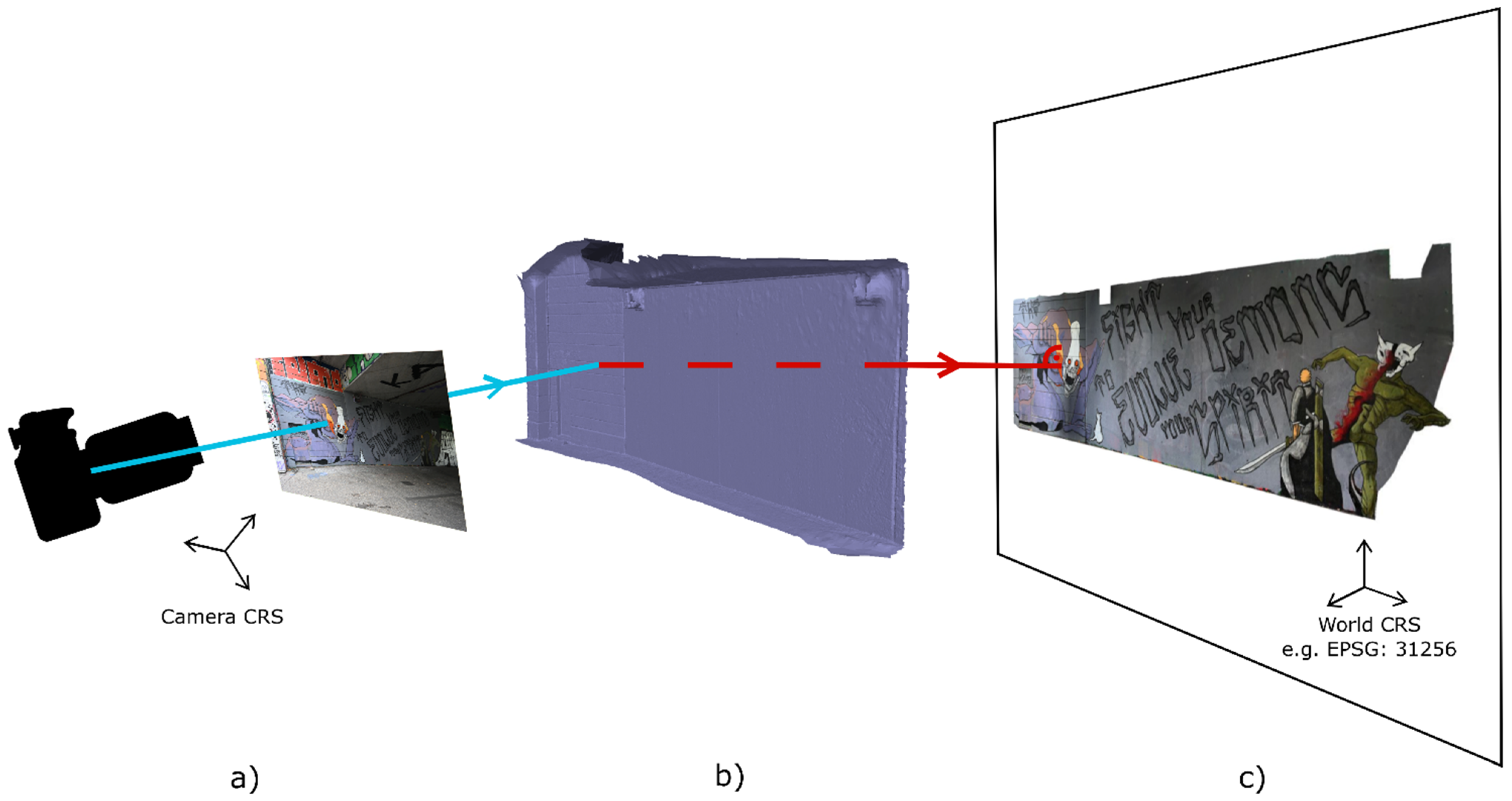
As outlined, photographs are an essential means to document graffiti. However, all photos suffer from various distortions, mainly caused by the camera’s central perspective projection (i.e., perspective distortion) and the relief of the depicted object (i.e., topographic distortion). Perspective distortions occur when the object is not a single plane parallel to the focal plane of the camera. This makes objects that are closer to the camera appear larger than objects that are farther away, and vice versa. Topographic distortions appear when the photographed object is not flat but features elements such as extruding or intruding doorframes or pillars. These surface undulations cause varying distances between the camera and the object, resulting in topographical displacements of these object elements and, thus, a misleading depiction of the overall object. Furthermore, photographs suffer from lens distortions mainly caused by unavoidable imperfections of the camera’s mechanical lens system realisation. Although usually small compared to the above-mentioned distortion types, they can and should also be accounted for, as they are visible in the images. An orthophoto removes all three types of distortions by transforming the photograph from its original central projection on the image sensor into an orthogonal projection in a selected object plane [25]. To achieve this orthorectification of digital photographs, three types of auxiliary data are necessary (Figure 1):
- (a).
- The cameras’ interior and exterior orientation parameters. The exterior orientation describes the camera’s absolute position and rotation at the moment of image acquisition. The interior orientation describes the camera’s internal geometry, including lens distortion parameters;
- (b).
- A digital, hole-free, continuous 3D model of the surface the graffito was created on (e.g., wall, bridge pillar or staircase);
- (c).
- A projection plane onto which the texture information from the photo(s) is orthogonally projected via previously intersecting the 3D surface model.
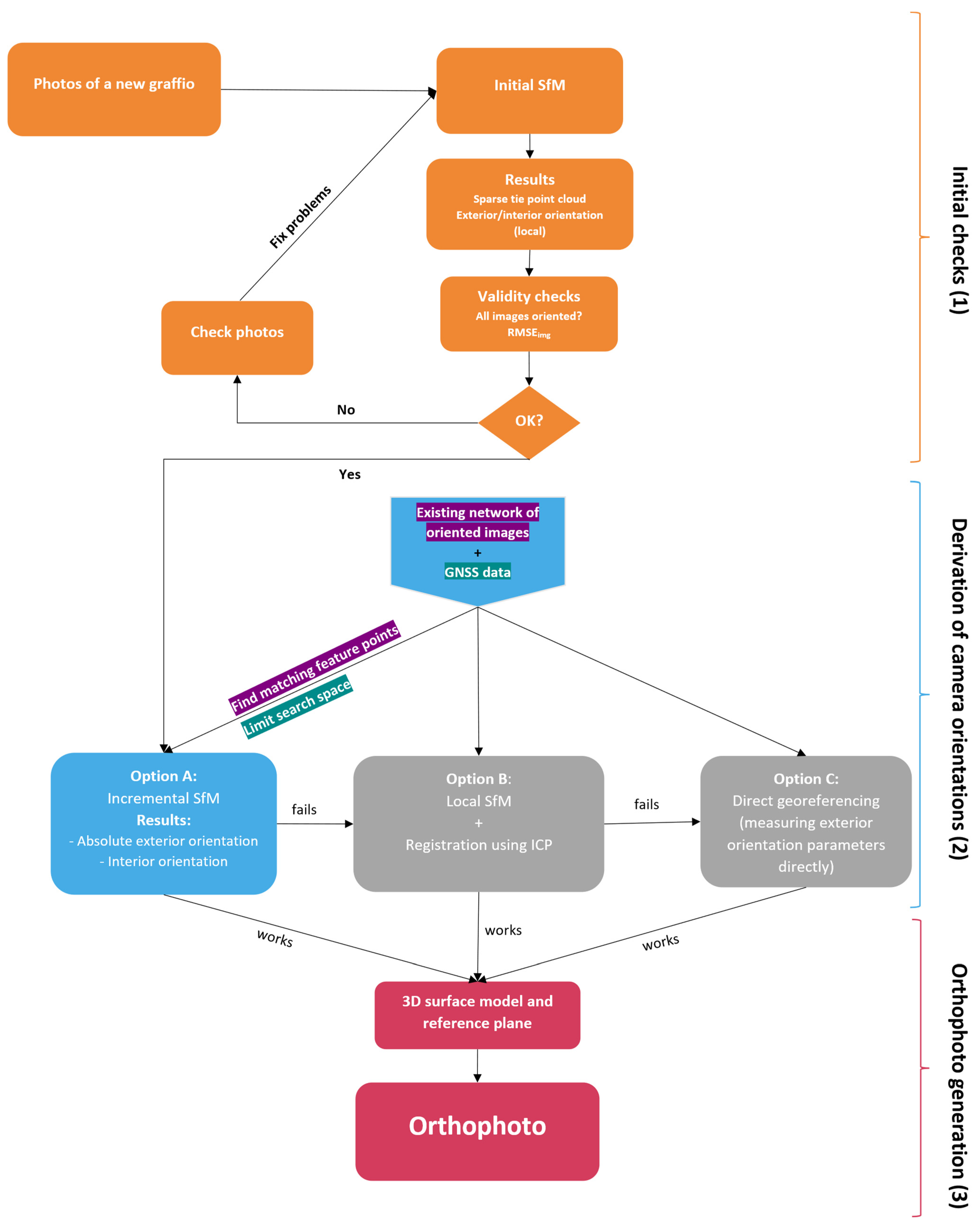
This paper details the conceptualisation, implementation and evaluation of our bespoke software tool AUTOGRAF, which enables the retrieval of these data from new graffiti photographs and an existing network of previously acquired images for which the interior and exterior orientation parameters were determined beforehand (see Section 2.1.1). Considering the pace at which new graffiti appear along the Donaukanal, a central requirement for AUTOGRAF is to keep manual intervention to a minimum. To achieve this, INDIGO’s photogrammetric pipeline (Figure 2) foresees three main processing steps which do not require human input:
- (1)
- Initial quality and consistency checks of the graffito images;
- (2)
- Estimation of the camera’s interior and exterior orientation;
- (3)
- Derivation of a digital 3D model of the graffiti-covered surface, computation of the (ortho-)projection plane (also referred to as reference plane) and creation of the final orthophoto.
The initial checks (1) aim to indicate whether the input is likely to provide reliable results or if parts of the input should be removed from the orthorectification process to increase reliability and decrease processing times. In the next step (2) the cameras’ interior and (absolute) exterior orientations are estimated. These parameters are retrieved using an incremental Structure from Motion (SfM) approach [26] and require the availability of an existing network of images with known absolute exterior orientation parameters: INDIGO’s so-called total coverage photo network. Lastly, (3), the newly oriented cameras are used to derive the 3D continuous surface model of the scene. The projection plane is approximated using the sparse point cloud, an intermediate result of (2). The pixel’s RGB values are (orthogonally) projected onto this projection plane.
The following sections detail the intermediate processing steps and show how AUTOGRAF was designed, implemented and tested on real-world examples.
2.1.1. Total Coverage Network
INDIGO’s current orthorectification approach necessitates an existing image network covering the whole research area and allowing the incremental orientation and addition of new photos into this network. This incremental SfM approach is detailed in Section 2.1.4. Here, an overview of the acquisition, processing and quality of INDIGO’s total coverage network is given (for more details, please consult [5]).
In autumn 2021, a so-called total coverage photography campaign was executed. During six days (30 September–1 October 2022 and 26 October–29 October 2022), almost 27 k photographs were acquired from INDIGO’s entire research zone using two camera/lens setups:
- Camera 1: Nikon D750 (24.2 MP)/Lens 1: Nikon AF-S NIKKOR 85 mm f/1.8 G @ f/5.6 (4609 photos)
- Camera 2: Nikon Z 7II (45.4 MP)/Lens 2: Nikon NIKKOR Z 20 mm f/1.8 S @ f/5.6 (22,097 photos)
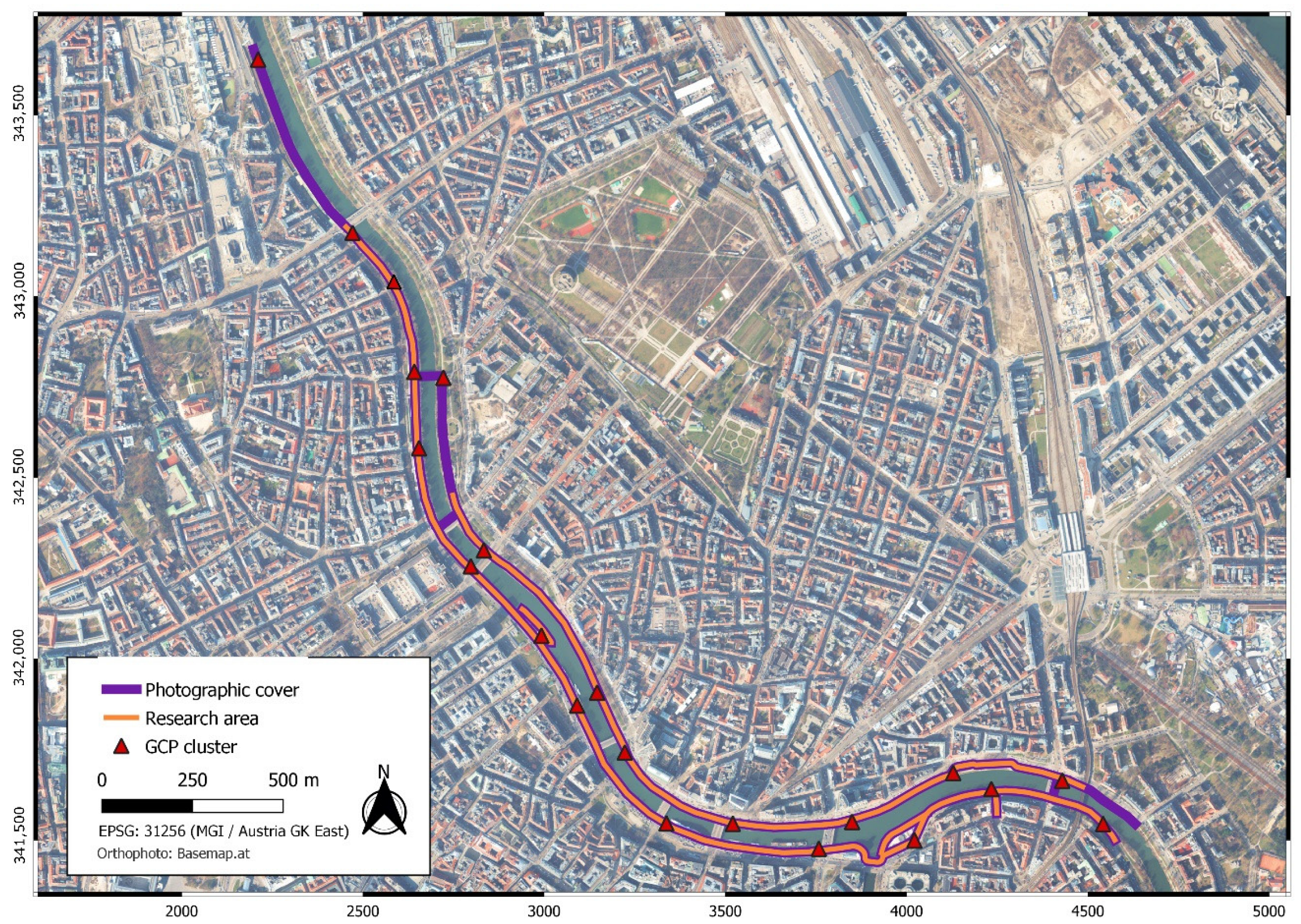
The acquired images cover ca. 14 km of surfaces along the Donaukanal (Figure 3), of which some parts are not within INDIGO’s research area. This extended coverage was performed because the exact extent of the monitored graffiti area was not clear at the moment of acquisition. Furthermore, photos were taken on and from bridges to connect both sides of the channel, which helps to mitigate drift effects in the image network.
As it was foreseen to orient the acquired images with an SfM approach, the photographer followed specific rules, such as photographing with a high image overlap and strictly avoiding gaps in the image network (i.e., areas with no overlapping images). Zooming and refocusing were avoided during the six acquisition days to retain the inner orientation parameters. This was ensured by fixing the focusing ring with tape. Furthermore, the images were taken with varying camera tilts (i.e., combining images captured perpendicular and oblique to the scene) to mitigate systematic errors in the derived camera orientations [27].
The acquired images were oriented in Agisoft’s Metashape Professional (version: 1.7.5) [28]. Only four out of the ca. 27 k photos could not be oriented successfully, although the graffiti-scape and infrastructure along and around the Donaukanal changed significantly during the one-month acquisition period (see [5] for more details).
To express the SfM results in real-world coordinates and to mitigate drift effects that inevitably accumulate at such large and elongated image networks, so-called ‘Graffiti-scape Control Points’ (GCPs) were incorporated into the network as constraints. Those GCPs were measured during a terrestrial surveying campaign utilising a Leica Viva 16 total station at equally distributed clusters along the Donaukanal (Figure 3). Overall, more than 500 GCPs, expressed in the MGI/Austria GK East coordinate reference system (EPSG:31256), were incorporated to constrain and georeference the final network of images. The remaining GCP residuals (RMSExyz = 1.8 cm) indicate that the camera locations were retrieved with an accuracy in the magnitude of a few centimetres. This large total coverage network serves three purposes in INDIGO:
- (1)
- It documents the graffiti status quo, thus establishing a starting point for monitoring and recording new graffiti;
- (2)
- It facilitates the generation of a digital, continuous 3D surface model of the whole research area in the form of a triangle-based polymesh. Since INDGO aims to create an online platform that offers visitors virtual walks along the Donaukanal, this surface model is called the 3D geometric backbone;
- (3)
- It establishes a dense photo network that can be used for incremental SfM.
2.1.2. Photo Acquisition and Data Management
The overarching aim of this study was the development of a workflow that allows a seamless and continuous throughput of graffiti photos to derive graffiti orthophotos from them. Besides photogrammetric solutions, this requires a strict and standardised image acquisition procedure and data management.
Starting in November 2021, INDIGO project members went to the Donaukanal to photograph new graffiti at least once per week (the so-called follow-up photography tours). Monitoring new graffiti is non-trivial given the large research area and the almost non-stop graffiti activity. INDIGO mainly monitors new graffiti via Instagram posts of graffiti creators that operate along the Donaukanal. In addition, INDIGO promotes the use of its own hashtag #indigodonaukanal. When a new creation surfaces, it gets indicated on a base map inside the ArcGIS Field Maps app from ESRI. This app runs on INDIGO’s tablets which support 4G LTE (fourth generation Long Term Evolution), so data can be stored and retrieved from the cloud 24/7. Whenever there is a follow-up tour, the photographer takes the tablet along to guide her/his tour.
Every new graffito is symbolised by a dark pink dot, which disappears when the photographer decides that it was properly documented. If the documentation conditions were suboptimal (for example, the graffito was partly sunlit, or blocked by a container), the dot’s status can be changed to “needs another go”, represented by an orange dot colour. When a new graffito is spotted during the follow-up photography, it gets documented as well. To ensure that the last method does not solely rely on visual memory, the ArcGIS Field Maps app also stores overview photos for all sections of the research area. When a new graffito gets photographed, the overview photo in the app gets ideally updated as well, so there is always a visual depiction of the latest graffiti status quo. Although this workflow has its merits, it also comes with many shortcomings. One of them is that many of the smaller graffiti (like tags or stickers) go unnoticed. To that end, the INDIGO photographers cover certain zones in their entirety once per month. Because this approach is also far from ideal (much can happen in one month and focusing on specific sections leads to bias in the records), an automatic change detection method based on repeat photography with GoPro HERO 10 Black cameras is in development.
When a new graffito is identified, the image acquisition for this graffito has to be performed in a way that allows the identification of common feature points (i.e., tie points) between the image set of the new graffito and the previous photos at that location that exists in INDIGO’s total coverage network. In many cases, the graffito scene and its environment have changed significantly between these two photography events. Thus, not only is the new graffito photographed but also its surroundings, enabling the establishment of tie points between the new and old images, even when the direct vicinity of the graffito has been altered.
In addition, the photographer must follow some rules that consider the subsequent SfM procedure, similar to the rules for the total coverage acquisition. This includes a large overlap between the acquired photos, which are collected with the optical axis perpendicular as well as inclined to the scene. The images perpendicular to the graffito are especially important for deriving the orthophoto because these images provide a homogenous spatial resolution (i.e., image scale) on the object (as opposed to the tilted ones). Furthermore, the camera should be regularly rotated at a 90° interval to generate portrait- and landscape-rotated photographs. Finally, during the image acquisition of one new graffito, the lens’ focal length (20 mm) and focusing distance are fixed to not alter the camera calibration parameters within one graffito block.
Before this entire image network of a graffito is captured, one photo of an X-Rite (now Calibrite) ColorChecker Passport Photo 2 is obtained as well as a spectrometer measurement of the incident illumination. Whereas the latter is important for the colourimetric processing of the images, the former serves as a backup to the spectrometer measurements. It also has an important function in the management of the photographs. Since these ColorChecker images can be automatically detected, they allow splitting an entire selection of graffiti images into individual, graffito-specific folders with a unique identifier.
Once these preparatory steps are completed, AUTOGRAF can be started by passing the folder paths to the program. AUTOGRAF is implemented as a Python add-on to Agisoft’s commercial photogrammetric software Metashape. The code, which can be freely downloaded from GitHub (https://github.com/GraffitiProjectINDIGO/AUTOGRAF, accessed on 29 September 2022), is distributed under the GNU General Public License v3.0.
2.1.3. Initial SfM and Quality Checks
Once the images are passed to AUTOGRAF, an initial checking procedure starts. These checks increase the reliability of the results and speed up the computation by detecting images which should be ignored in the further processing chain. Specifically, these checks are designed to flag photographs which are either of bad quality (e.g., blurry) or erroneously assigned to a certain graffito image folder and thus do not match the other images in the stack. They might also deliver inaccurate results for the estimation of the camera orientation parameters.
At the beginning of these checks, an initial local SfM is applied. This local SfM results in each image’s interior and relative exterior orientation parameters. Images for which these parameters cannot be retrieved do not share a sufficient number of common feature points with the other images in the folder and are thus likely of too low quality or show a different graffito scene and were incorrectly assigned. These images are ignored during the remaining processing pipeline, reducing the computation times.
All images that Metashape successfully orients undergo an additional quality check, during which the so-called Reprojection Error (RE) for each reconstructed 3D tie point is computed. RE is defined as the image distance between the measured location of a tie point in the image (Pmeasured) and the 2D projection of its reconstructed 3D tie point (Pprojected). It is expressed in pixels and computed for each derived tie point in every image. To get a per image representation of the RE, the root mean square error (RMSE) of all REs for the examined image are computed (RMSEimg):
The RMSEimg is thus a quantitive measure indicating the quality of a bundle block adjustment result for a specific image. This information is used to detect images for which the computed orientation parameters are not derived accurately. It would be possible to remove all images which exceed a certain RMSEimg threshold, increasing the accuracy of the subsequent workflow. However, removing images involves the danger of failing to compute a hole-free orthophoto for a specific graffito. Thus, no images are removed based on their RMSEimg. Instead, the RMSEimg is stored for each image and can be used to manually finetune the results if needed or for analysing the achieved accuracy.
2.1.4. Incremental SfM Approach
An important step towards the derivation of the orthophoto is the computation of the camera orientations. This is solved by applying a so-called incremental SfM routine during which the new graffiti images that passed the initial quality checks are incrementally oriented and self-calibrated (i.e., solving for the interior orientation) by adding them to the existing image network of the whole Donaukanal [5]. This approach relies on tie points that can be established between the existing and new photos, again highlighting the importance of a considerate image acquisition which depicts enough of the invariant surrounding.
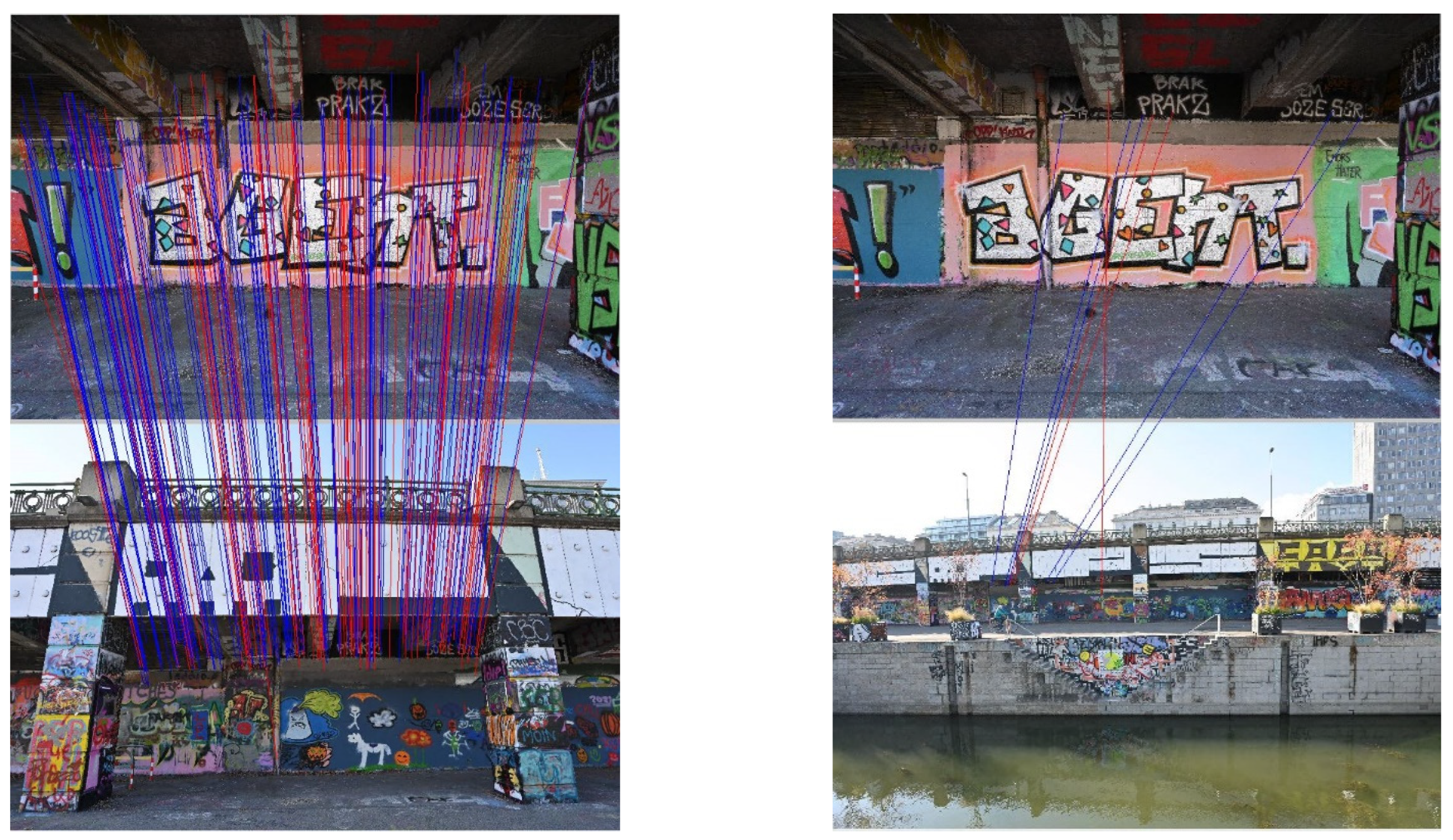
Figure 4 indicates the feasibility of this approach: tie points could be established between images taken on 27 October 2021 and 17 December 2021, although most parts of the graffiti were overpainted during these 52 days. Some valid matches were even found for an image taken on an island almost in the middle of the Donaukanal (Figure 4).
To accelerate the incremental SfM computation, Metashape preselects overlapping photo pairs from seriously downsampled images before it conducts the image matching using a user-set pixel count. Although this “generic preselection” [29] speeds up the processing significantly, an additional limitation of the search space is advantageous considering the enormous amount of image data that need to be processed. This is achieved by utilising position data to filter photos which are irrelevant for the currently processed graffito image stack. An external GNSS receiver gathers these position data. Currently, the Solmeta GMAX geotagger is mounted on the Nikon Z7 II cameras to estimate the camera’s location during image exposure. The GMAX is a dual satellite positioning system utilising GPS and BeiDou satellites. It writes the camera station’s WGS84 coordinates (EPSG:4326) as image metadata in the form of standardised Exif (Exchangeable image file format) tags. AUTOGRAF transforms these WGS84 coordinates into the CRS of the whole image network (EPSG:31256). These initial estimations for the camera locations are used to define a radius beyond which photos are ignored for the incremental SfM. As the estimated positions tend to be unreliable beneath bridges and because the GMAX geotagger does not provide directly accessible positional accuracy estimates, the search radius was chosen sufficiently large to allow the orientation of images acquired beneath bridges. Right now, a 30 m search radius is set. Smaller radii sometimes resulted in photos not being oriented due to a lack of overlapping imagery. INDIGO is currently working on a camera-mounted Real-Time Kinematic (RTK) GNSS receiver. Besides more accurate coordinates, this solution will also provide accuracy estimates allowing to set a dynamic radius for the image selection.
2.1.5. Generation of the 3D Model and Computation of a Custom Projection Plane
When the camera orientations for each graffito photo set are derived, the 3D model of the graffito scene and the projection plane can be computed. The 3D model is generated by a depth-map-based multi-view stereo matching [30], which results either in a dense point cloud or directly in a triangle-based polymesh, both digitally representing the surface. If one opts for the point cloud option, Metashape can also interpolate (i.e., mesh) this dense collection of points into a polymesh, the advantage being that one can first filter and classify the dense point cloud before meshing. Tools for filtering the facets of the polymesh are also present, albeit more basic. INDIGO’s AUTOGRAF exploits the integrated “isolated component filter”, which removes parts of the 3D meshed surface model not connected to the main part. The main part is defined as the mesh component containing most vertices, which in practically all cases corresponds to the graffito-covered surface where the photographic coverage peaks. In that way, isolated structures such as branches or street lamps occluding the graffito in the final orthophoto are removed.
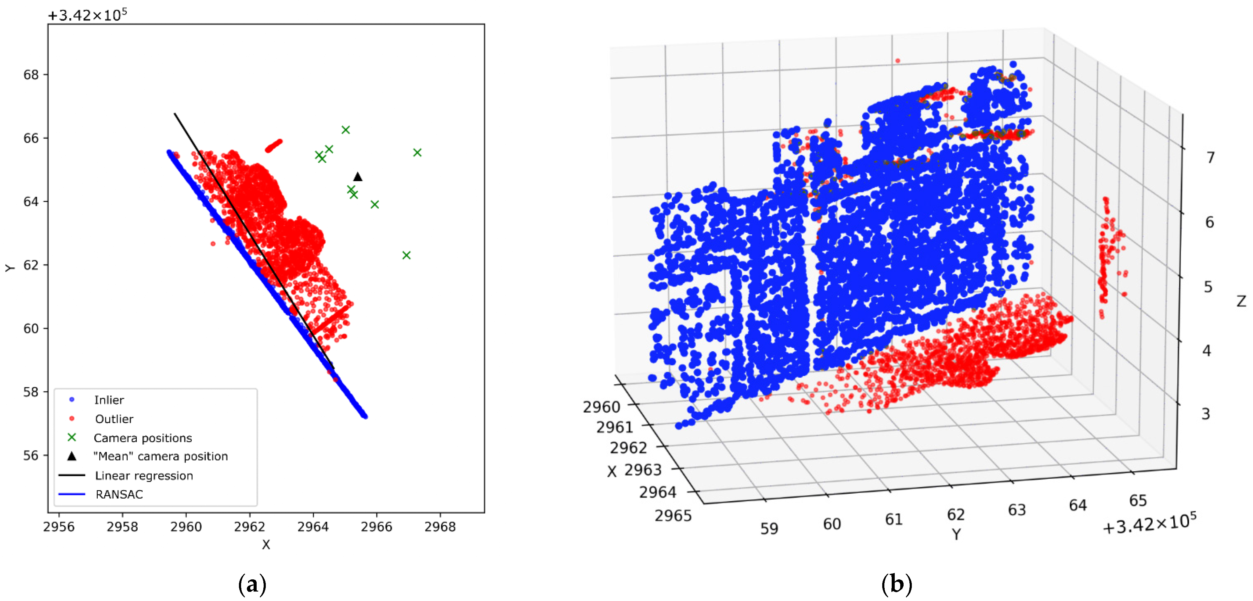
However, the derivation of the projection plane necessitates a bespoke solution as the graffiti-painted walls are arbitrarily oriented in space and generally not ideal planes. They are sometimes curved and feature ex- or intruding elements such as pillars or doorframes. Thus, a reference plane, which is perpendicular to the orthogonal viewing direction, can only be approximated to the graffito surface (Figure 1). This is achieved by fitting an individual plane for every graffito based on its previously derived tie point cloud. The idea behind this is that most tie points are located on the graffito-covered wall, which allows deriving one major plane (the projection plane) from the derived tie point cloud via plane adjustment. Before the plane is adjusted, tie point outliers are removed from the point cloud using the RANdom SAmple Consensus (RANSAC) method.
RANSAC is a robust outlier detection method first introduced by Fischler and Bolles in 1981 [31]. It repeatedly and randomly subsamples the input data (e.g., the cloud of 3D tie points in this case) and uses these n subsamples to derive the parameters of a mathematical model (e.g., parameters of a plane equation). Every subsample only contains the minimum sampling necessary for unambiguously determining the model parameters. Each set of model parameters is then tested against the data not used for the parameter computation. Data that fit the estimated model well, according to a certain threshold t (e.g., t = 10 cm), are considered the consensus set (i.e., the data inliers). The set of model parameters that result in the largest consensus set is the final result of RANSAC, and the resulting consensus set can be used to split the data into in- and outliers (Figure 5). A user sets the number of subsamples (n) and the uncertainty threshold (t) above which data points are considered outliers. For this application, n and t were set to 1000 and 10 cm, respectively.
After the inlier points of the plane are detected, they are used to derive the plane parameters by least-squares minimisation of the point’s orthogonal distances to the plane, which can be solved by computing the eigenvectors of the matrix of centralised moments. The computation of these eigenvectors yields the plane parameters in the form of two normalised direction vectors parallel to the plane (, ) and one perpendicular () to the plane. AUTOGRAF automatically derives those three vectors and passes them to Metashape in the form of a matrix M:
where the subscripts in etc., denote the individual (x-, y-, z-) components of the direction vectors.
2.1.6. Orthophoto Creation and Boundary Selection
With the known camera orientations, the 3D mesh of the graffito surface and the projection plane, the orthophoto is generated in Metashape. Metashape also supports orthophoto mosaicking. This technique allows the blending of orthophotos by stitching them along so-called seamlines to create one complete and continuous orthophoto, also referred to as orthophotomosaic. The great advantage of this orthophoto blending is that an orthophoto of the whole graffito can be derived even when there is no single image covering the complete graffito, thus enabling the depiction of extensive surfaces. Furthermore, it allows for analysing a graffito in much higher spatial resolutions as many close-range images can be stitched together into one orthophoto.
As the current approach relies on photos depicting large parts of a graffito’s surroundings, the graffito of interest often covers only a portion of the derived orthophoto. A graffito outline is defined manually to remove irrelevant parts, which is, together with selecting and assigning the images to the corresponding graffiti, the only manual intervention needed during the whole orthophoto generation process. Currently, the boundary selection is performed on one overview image—acquired directly after the ColorChecker photo—covering most or, ideally, all parts of the graffito of interest. The 2D image coordinates of the graffito’s outline are picked in image space. By intersecting the image ray that goes through the camera’s projection centre and the picked image coordinates with the 3D model, the 3D world coordinates (EPSG:31256) are derived (also called monoplotting). If the 3D surface model is not available for a graffito boundary point, the image ray is instead intersected with the RANSAC-derived projection plane of the scene. The calculated 3D world coordinates are stored as a polygon in a vector file and serve as a realisation of the georeferencing. Selecting the graffiti boundaries is necessary to avoid that the final orthophoto contains parts of the graffito-scene which appear highly distorted, are incorrectly textured or contain holes due to an insufficient image overlap. Such parts usually do not add value to the graffiti orthophotos but consume significant disk volume. Therefore, they are omitted. However, it is to be noted that these boundary selections introduce a certain subjectivity, as a graffito boundary is often fuzzy and difficult to identify. Furthermore, the boundary selection does not contradict the importance of placing the graffito in its native context, which is achieved in a later step when the derived georeferencing information enables positioning the graffito (as an orthophoto or a texture patch for the 3D mesh) in a virtual 3D environment, therefore also relating to neighboring graffiti. The implementation of this environment is still being researched in the context of INDIGO and not within this paper’s scope.
Finally, the orthophoto is exported with three raster cell sizes: 1 cm and 1 mm and its native Ground Sampling Distance or GSD (usually between 0.5 and 1 mm), which is primarily determined by the camera distance to the graffito during image acquisition. The georeferencing information containing the transformation parameters is separately stored and allows assigning 3D world coordinates to every pixel of the 2D orthophoto.
2.2. Orthorectification Experiment
2.2.1. Experimental Setup
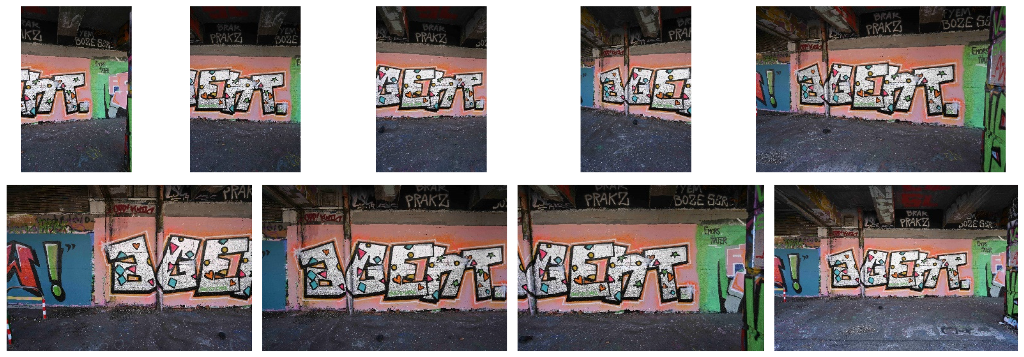
To see how AUTOGRAF would behave in a real-world scenario, 100 graffiti were randomly selected from all graffiti documented between November and December 2021. Those images were separated into individual folders, each containing all photos acquired for one graffito. To store the 14-bit of colour data acquired by the digital camera, INDIGO’s final workflow will rely on colourimetrically processed RAW photos that are saved as 16-bit lossless compressed TIFF files. However, this processing pipeline was not finished when running these tests, which explains why this test was run with minimally compressed JPEG files, in-camera generated from the RAW photos. An example of one image set can be seen in Figure 6. The total number of images used in the experiment was 826, with a total file size of 27.0 GB. On average, a graffito folder contains 8 (min/max: 3/63) photos from different positions and viewing angles. The wide range in the number of photos per graffito is due to a graffito folder with 63 images. This graffito is located very close to the water and had thus to be photographed in 63 small snippets to be entirely covered (Figure 8b). The folder with only three photos is considered a side-effect of starting a documentation project where everybody needs to gradually learn how to acquire a good image network.
2.2.2. Experiment Evaluation
The experiment mainly aimed at answering two questions: (A) are the results of the expected quality, and (B) does AUTOGRAF allow sufficiently fast processing of large amounts of graffiti images, necessary for the constant monitoring of the graffiti-scape along the Donaukanal? The latter (B) is relatively straightforward to answer by measuring the time needed to produce an average orthophoto and comparing this duration with the number of graffiti that are expected to be processed in a certain time period. However, evaluating the quality of the orthophotos (A) is more difficult due to the unavoidable subjectivity of the assessment. Notwithstanding, a classification scheme was introduced that allows the categorisation of each orthophoto into four classes (0, 1a, 1b, 2; Table 1). To make the experiment evaluation replicable and transparent, we uploaded the resulting orthophotos (along with the code) to the following GitHub repository: https://github.com/GraffitiProjectINDIGO/AUTOGRAF (accessed on 29 September 2022).
To separate AUTOGRAF-related problems from problems that are mainly input data-related and thus neither solvable by improving AUTOGRAF nor by human intervention during the orthorectification process, the distinction between 1a and 1b was made. This helps to distinguish actual shortcomings of the developed methodology (classified as 1b) from general challenges that occur during image acquisition (classified as 1a), such as parts of the graffiti that are not covered by the photographs or poor image geometry (e.g., all images taken from the same or very similar positions). In many cases, the problem might be solvable by both rephotographing or manual intervention during orthorectification. Those cases are classified as 1b (AUTOGRAF-related) as this experiment aimed to compare AUTOGRAF’s performance against the performance of a hypothetical manual operator. Furthermore, rephotographing is usually more time-consuming and often not possible as the graffito might be covered already. The georeferencing accuracy of the resulting orthophotos was assessed by comparing the derived boundary polygons with an infrastructural vector map provided by the city of Vienna.
3. Results
3.1. Initial Local SfM and Incremental SfM
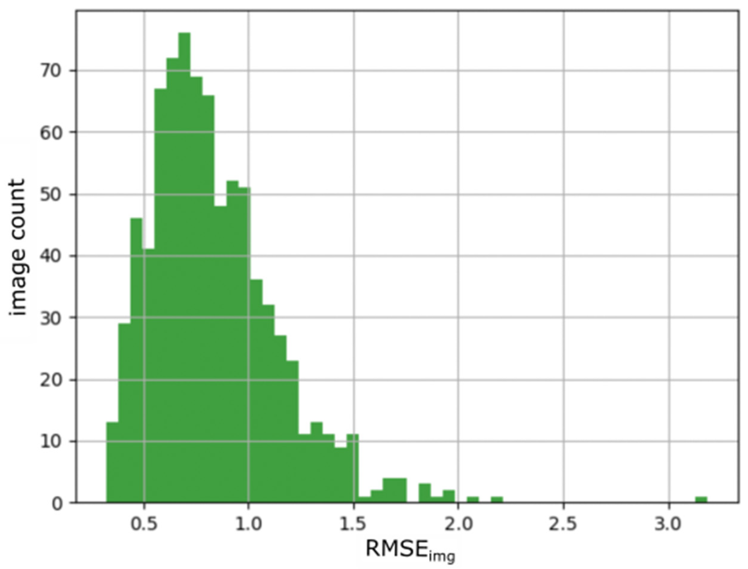
During the initial SfM procedure, all images were oriented locally and self-calibrated in their respective graffito subblock. For 823 out of 826 images, the local SfM procedure successfully ended, indicating both high performance of the feature point extraction plus subsequent bundle block adjustment as well as thorough data acquisition and management. The mean RMSEimg for the remaining 823 images is 0.83 ± 0.31 pixels (Figure 7).
Concerning the derivation of absolute exterior and interior orientation parameters, the incremental SfM approach was successful for 752 out of the 823 images (91%). The 752 oriented images correspond to 97 graffiti for which the complete image set (i.e., all images assigned to the graffito) was successfully oriented and one graffito image set for which only one image could be oriented. The 71 photos which could not be added to the existing total coverage camera network belong to three graffiti (Figure 8). The graffito (Figure 8b), which was covered with 63 images, is among the failures. Only one of its 63 images was successfully oriented, explaining the diverging success rate between the number of oriented images and oriented graffiti blocks (91% oriented images vs. 97% successfully oriented graffiti blocks). The mean RMSEimg for the 752 incrementally oriented images is 1.65 ± 0.44 pixels.
Inspection of the graffiti blocks that could not be oriented (Figure 8) shows that they hardly depict the surrounding environment, such as other graffiti or neighbouring infrastructure, making it impossible to find tie points between these images and those of the existing total coverage photographs. This likely could have been resolved in all three cases by rephotographing the scene. However, it is to be noted that in some cases (Figure 8a,b), the narrow operating space significantly complicates proper image acquisition. Certain imperfections in image acquisition will thus remain unavoidable or can only be mitigated with additional efforts such as the use of a very-wide angle lens (e.g., 10 mm) or crossing the Donaukanal to photograph the graffito with a telephoto lens (e.g., 105 mm) to depict larger portions of the scene. Overall, the achieved success rate (97%) of the incremental SfM is highly satisfactory.
3.2. Derivation of the 3D Surface Model and the Projection Planes
The results from the incremental SfM routine for every graffito subblock (i.e., the exterior and interior camera orientations and tie points) are used to derive scene-specific 3D surface meshes and projection planes for every graffito scene. For the 3D meshing, the implementations provided by Metashape are used. The quality of the resulting 3D models is highly dependent on the number of input images. For some graffiti, only three to five images were acquired, which suffices in most cases to derive a 3D representation of the graffiti-covered surface but in some cases leads to small artefacts in the retrieved mesh. For the tested graffiti, however, these artefacts hardly occurred on the parts of the mesh where the graffito of interest is located but mainly on the edges of the model, towards which the image coverage decreases. Overall, these imperfections did not notably influence the orthorectification results.
Concerning the projection plane derivation, no notable problems occurred. A visual examination of the classified point clouds confirms the robustness of the applied RANSAC method. The derived projection planes approximate the graffito-covered surfaces well.
3.3. Quantity and Quality of the Derived Orthophotos
The orthophotos were classified based on the classification scheme introduced in Table 1. This classification (Table 2) shows that 95% of the tested graffiti were orthorectified without major flaws (class 1a, 1b or 2). For 80% of the graffiti, orthophotos without or with only marginal flaws were generated (class 2). 15% of the Orthophotos exhibited minor problems such as minor occlusions, distortions, blurriness or underexposure (class 1a and 1b). Most minor flaws (10 out of 15) were related to the automated editing of the 3D model (class 1b). In some cases, parts of the model that occlude the graffito were not removed and thus caused occlusions in the final orthophoto. The example for 1b in Table 2 depicts such a case: a pile of broken wooden planks located in front of the graffito causes part of the graffito to be occluded. For this and for other graffiti, an improved image acquisition would most likely solve the issue, but this would be more time-consuming than manual editing of the 3D model and is likely not possible anymore due to the destruction of the graffito. Thus, these flaws were still considered AUTOGRAF-related. The deficits of the remaining 5% of orthophotos with minor flaws (class 1a) are primarily associated with inadequate or insufficient input data, which can only be resolved by rephotographing the graffito and rerunning the orthorectification pipeline. The reasons for the partial failure in these cases were bad illumination conditions at the time of image acquisition (causing shadows or very dark areas), too few photographs or unfavourable image acquisition geometry. The latter two caused some graffiti to be warped or blurry. The 1a orthophoto included in Table 2 depicts a graffito which was photographed from five almost identical positions causing a poor measurement geometry which leads to blurry parts in the orthophoto and a (GSD) of only 2.3 mm. The average GSD of all derived orthophotos is 0.9 mm, indicating that, on average, spatial details of 2.0 mm should be well visible. It needs to be stressed again that the classification is subjective as it is based on human interpretation.
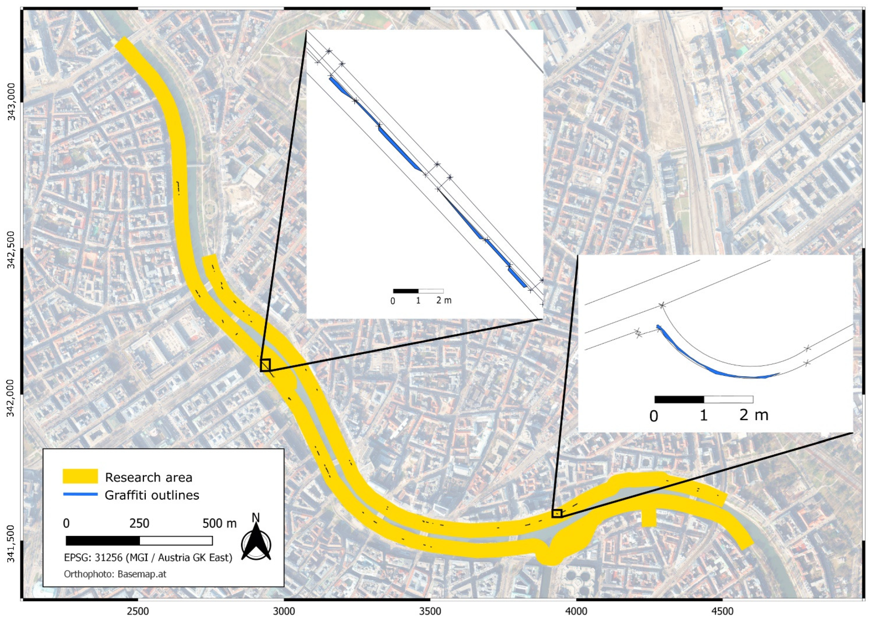
Figure 9 shows the overall accuracy of the graffiti’s absolute georeferencing by overlaying the obtained results with the so-called multi-purpose map (German: Mehrzweckkarte), an official and freely available map created by the City of Vienna (https://data.wien.gv.at, accessed on 29 September 2022). This map is derived from terrestrial surveying campaigns and depicts significant features along the Donaukanal, e.g., walls, bridge pillars, and staircases. The two detailed maps in Figure 9 show deviations from 0 cm up to a maximum of 22 cm between Vienna’s multi-purpose map and the derived graffiti outlines. The bigger part of these deviations originates likely from the generalisation of Vienna’s multi-purpose map. This map exhibits a comparatively low sampling of terrestrial measurements, and most points in the multi-purpose map correspond to points on the ground, while the graffiti are often located several metres above the ground. A smaller portion of the deviations might also be associated with residual drift effects of the existing camera network and georeferencing errors. Even though our results might still contain errors in the order of some cm, there is an overall excellent agreement with the reference data.
3.4. Feasibility of the Workflow
Besides the quality of the results and the large-scale applicability of the approach, computational effort plays an essential role in the assessment of the developed orthorectification pipeline. Thus, a strong emphasis is laid on the processing efficiency of the program both during development and testing. This experiment was conducted on two different computer setups, also to examine the influence of different hardware components on the computation times. Apart from the PC’s hardware components, the experimental setup and results were identical. The PC specifications can be found in Table 3.
In total, it took 22 h 50 min (Setup A) and 10 h 33 min (Setup B) to derive the 97 graffiti orthophotos from the 826 graffiti images (Table 4). The manual preparatory tasks took approximately 1 h 20 min and involved the splitting of all photos into individual folders (50 min; the automated splitting based on the ColorChecker target was not implemented yet) and the graffiti boundary selections of the overview images (20 min) in the image space. An average graffito required thus 42 s of manual intervention. This manual preparation was only done once and used for both experiment runs.
Concerning the pure processing times (without manual interventions), an average graffito image set was processed in 13 min (Setup A) and in 5 min 38 s (Setup B), highlighting the large dependency on the utilised hardware components. The most time-intensive computation step for both setups was the final creation of the orthophoto. This step includes demanding computational tasks such as creating the 3D surface model.
Extrapolation of these results shows that the current workflow in combination with PC setup B allows the orthorectification of ca 6800 graffiti image sets, featuring some 56 k images, per month. Although this number might not be fully reachable in the actual operational use of the software, it will still allow the sufficiently fast processing of the awaited amounts of graffito photographs. As a comparison, the number of images acquired by the INDIGO team between January 2022 and July 2022 was, on average, circa 4000 per month, with a maximum of 6315 photos in May.
4. Discussion and Outlook
This paper introduced a novel methodology to automatically derive georeferenced and distortion-free orthophotomaps from graffiti photos acquired along Vienna’s Donaukanal. AUTOGRAF was applied to a test dataset of 826 images corresponding to 100 graffiti. It managed to satisfactorily orthorectify and georeference 95% of the tested graffiti photographs, highlighting its reliability. The exact georeferencing accuracy is difficult to determine due to the generalisation of the (2D-)reference data, but typically in the order of a few cm in planimetry and thus satisfactory. The average processing time of less than 6 min per graffito shows that AUTOGRAF will be able to keep up with the expected hundreds of newly documented graffiti each month.
Although the quality of the derived graffiti orthophotos is, on average, very good, the experimental results also indicate potential pitfalls of the methodology, such as a high dependency on application-specific image acquisition. The acquired photographs must follow various SfM-specific acquisition rules and need to depict large parts of the surrounding environment. For three graffiti, the images lacked sufficient overlap with invariant parts of the graffito’s neighbouring environment. However, fully preventing this from happening is difficult due to space constraints in some scenes, while the current photographing procedure already requires substantial time, physical and concentration efforts from the photographer. That said, photographing procedures and hardware are continuously revisited to maximally avoid such situations.
An alternative to the currently implemented incremental SfM method would be the direct georeferencing of photographs. This would involve equipping the camera with an RTK GNSS receiver and an Inertial Measurement Unit (IMU) to obtain the exterior camera orientation parameters directly. Experience with low- and high-end IMUs connected to digital photo cameras was already gathered in previous archaeological photographing campaigns [32,33]. If INDIGO can also add a low-cost RTK GNSS setup on top of the camera, it would allow bypassing the relatively computation-intensive tie point extraction and image-matching procedures of the incremental SfM. Furthermore, only one photograph of a graffito could suffice to derive an orthophoto in most situations, thereby significantly reducing the time-consuming photo acquisition and processing. More images would, however, be needed if the geometry at the scene changed drastically compared to the time of the total photographic coverage (e.g., due to construction works). Since a multitude of images is required to obtain reliable interior orientation parameters, INDIGO should then also evaluate if these parameters can be fixed without compromising orthophoto accuracy. Furthermore, several detailed photographs would still be necessary for extensive graffiti, as an overview image would otherwise exceed INDIGO’s envisioned photo GSD of 1 mm. However, the biggest drawback of this method, besides the costs for hardware acquisition, is the expected lower georeferencing accuracy. Even high-end hardware would likely not be able to compete with the SfM-derived results and would even fail when the GNSS signal is obstructed (e.g., beneath bridges). However, as explained before, the combination of a good IMU with an RTK-enabled GNSS setup could always constrain the image search space for the incremental SfM procedure more reliably.
Another potential alternative to the incremental SfM approach could locate the locally derived tie point cloud in the higher-order reference frame via an Iterative Closest Point (ICP) registration approach [34]. This method likely delivers results with similar accuracies as the current incremental SfM approach and could serve as a backup solution if images of a new graffito cannot be tied to the existing image network. By utilising additional information obtained from RTK GNSS/IMU sensors as described above, an ICP-based approach may also achieve similar processing times.
Another challenge that INDIGO aims to tackle in the future is occlusions caused by pillars, vegetation or other structures located in front of the graffito, and that cannot always be completely removed with the mesh filtering currently implemented. While the isolated mesh component filtering solves the problem of occlusions for most graffiti scenes, sometimes the obstructing elements are connected to the main part of the model and thus are not removed automatically. A more reliable filtering method could also use the RANSAC-derived plane information and filter vertices of the 3D model which exceed a certain distance to the plane. Implementing this distance-based mesh filtering might solve the problem of remaining occlusions in the orthophotos for some cases and further improve the results. However, more tests and research need to be done on this matter, which is why this feature is not yet included in AUTOGRAF.
Lastly, INDIGO’s total coverage network and resulting 3D surface mesh (i.e., the geometric backbone) is a central but costly prerequisite as it requires diligent and extensive data acquisition, management and processing. However, it only needs to be established once, and due to INDIGO’s incremental SfM approach, large parts of the image network are regularly updated as photographs of new graffiti are added soon after they appear. Only for more extensive structural changes such as the construction of buildings or repair of bridges, and for regions which are not very frequently photographed due to lower activity of graffiti creators, a more extensive or even complete update of the geometric backbone might be necessary in the future. Another issue that could occur when more and more images are added to the image network is the accumulation of ‘net tensions’ in the entire camera network. They occur because the orientation of the image network is not homogenous and kept fixed. Thus, existing errors in the network may propagate into the incrementally added images and result in increased errors. Mitigating these ‘net tensions’ can be achieved by regularly rerunning a full bundle block adjustment on the incrementally updated camera network, but this is again a topic that will be explored in more depth later.
As outlined, there are still possibilities to optimise the current workflow. However, the results of the conducted experiment suggest that with the present implementation, AUTOGRAF can derive high-quality orthophotos from several thousand graffiti photos each month. This suffices to keep track of the high pace at which graffiti are created and photographed along the Donaukanal. The proposed framework thus provides a solid basis for processing the awaited terabytes of image data. Of course, the efficient acquisition and managing of the input and output images, (semi-)automatically keeping track of all the changes along the vivid graffiti-scape and disseminating the results to the general public are challenges that still require diligent and innovative research.
Nevertheless, with AUTOGRAF, an essential step towards the automated high-quality digital preservation of graffiti has been made. Lastly, it should be mentioned that the developed workflow is not restricted to use within the INDIGO project but might also serve a wide variety of (cultural heritage) applications at different locations. Although AUTOGRAF is currently restricted to the orthorectification of imagery from planar or nearly planar surfaces (e.g., slightly curved walls), it can also be applied to more complex surfaces for which the georeferenced 3D mesh can still be of interest. We hope that making the Python source code publicly and freely available encourages others to profit from our research.
Author Contributions
Conceptualization, B.W., G.J.V. and N.P.; Data curation, B.W. and G.J.V.; Formal analysis, B.W.; Funding acquisition, G.J.V. and N.P.; Methodology, B.W., G.J.V. and N.P.; Project administration, G.J.V. and N.P.; Resources, G.J.V., S.W. and N.P.; Software, B.W. and M.W.; Supervision, G.J.V. and N.P.; Validation, B.W.; Visualization, B.W.; Writing—original draft, B.W.; Writing—review and editing, G.J.V., C.R., J.S., J.O.-S. and N.P. All authors have read and agreed to the published version of the manuscript.
Funding
INDIGO is funded by the Heritage Science Austria programme of the Austrian Academy of Sciences (ÖAW).
Institutional Review Board Statement
Not applicable.
Informed Consent Statement
Not applicable.
Data Availability Statement
The AUTOGRAF source code, a manual on how to use AUTOGRAF and the classified orthophotos from the conducted experiment can be downloaded from INDIGO’s GitHub repository: https://github.com/GraffitiProjectINDIGO/AUTOGRAF (accessed on 29 September 2022). AUTOGRAF is written in Python and is built as an add-on to Agisoft’s Metashape Professional, a commercial photogrammetry software. AUTOGRAF is distributed under the GNU General Public License v3.0.
Conflicts of Interest
The authors declare no conflict of interest.
References
- Baird, J.A.; Taylor, C. Ancient Graffiti in Context: Introduction. In Ancient Graffiti in Context; Routledge: Oxfordshire, UK, 2010; Volume 133, pp. 17–35. [Google Scholar]
- Masilamani, R. Documenting Illegal Art: Collaborative Software, Online Environments and New York City’s 1970s and 1980s Graffiti Art Movement. Art Doc. J. Art Libr. Soc. North Am. 2008, 27, 4–14. [Google Scholar] [CrossRef]
- Ross, J.I.; Bengtsen, P.; Lennon, J.F.; Phillips, S.; Wilson, J.Z. In search of academic legitimacy: The current state of scholarship on graffiti and street art. Soc. Sci. J. 2017, 54, 411–419. [Google Scholar] [CrossRef]
- De la Iglesia, M. Towards the Scholarly Documentation of Street Art. Str. Art Urban Creat. J. 2015, 1, 40–49. [Google Scholar]
- Verhoeven, G.; Wild, B.; Schlegel, J.; Wieser, M.; Pfeifer, N.; Wogrin, S.; Eysn, L.; Carloni, M.; Koschiček-Krombholz, B.; Molada Tebar, A.; et al. Project INDIGO–Document, disseminate & analyse a graffiti-scape. Int. Arch. Photogram. Remote Sens. 2022, 46, 513–520. [Google Scholar]
- Ringhofer, A.; Wogrin, S. Die Kunst der Straße–Graffiti in Wien. Wiener 2018, 428, 46–53. [Google Scholar]
- Kraus, K. Photogrammetry—Geometry from Images and Laser Scans; Walter de Gruyter: Berlin, Germany, 2007. [Google Scholar]
- Novak, D. Methodology for the Measurement of Graffiti Art Works: Focus on the Piece. World Appl. Sci. J. 2014, 32, 40–46. [Google Scholar]
- Bengtsen, P. The Street Art World; Almendros de Granada Press: Lund, Sweden, 2014. [Google Scholar]
- Bengtsen, P. Decontextualisation of Street Art; Cambridge University Press: Cambridge, UK, 2019; Volume 9, pp. 45–58. [Google Scholar]
- Mavromati, D.; Petsa, E.; Karras, G. Theoretical and practical aspects of archaeological orthoimaging. Int. Arch. Photogram. Remote Sens. 2002, 34, 413–418. [Google Scholar]
- Chiabrando, F.; Donadio, E.; Rinaudo, F. SfM for orthophoto generation: A winning approach for cultural heritage knowledge. In Proceedings of the 25th International CIPA Symposium, Taipei, Taiwan, 31 August–4 September 2015; pp. 91–98. [Google Scholar]
- Agnello, F.; Lo Brutto, M.; Lo Meo, G. DSM and Digital Orthophotos in Cultural Heritage Documentation. CIPA XX Torino Italy 2005, 1, 49–54. [Google Scholar]
- Dorffner, L.; Kraus, K.; Tschannerl, J.; Altan, O.; Külür, S.; Toz, G. Hagia Sophia-Photogrammetric record of a world cultural heritage. Int. Arch. Photogram. Remote Sens. 2000, 33, 172–179. [Google Scholar]
- Kurashige, H.; Kato, J.; Nishimura, S. The Colored Comparison of the Wall Sculpture with 3D Laser Scanner and Orthophoto. In Proceedings of the ISPRS Working Group V/4 Workshop, 3D-ARCH 2005, Venice, Italy, 22–24 August 2005. [Google Scholar]
- Verhoeven, G.; Sevara, C.; Karel, W.; Ressl, C.; Doneus, M.; Briese, C. Undistorting the past: New techniques for orthorectification of archaeological aerial frame imagery. In Good Practice in Archaeological Diagnostics: Non-Invasive Survey of Complex Archaeological Sites; Corsi, C., Slapšak, B., Vermeulen, F., Eds.; Natural Science in Archaeology; Springer: Cham, Switzerland, 2013; pp. 31–67. ISBN 978-3-319-01784-6. [Google Scholar]
- Palomar-Vazquez, J.; Baselga, S.; Viñals-Blasco, M.-J.; García-Sales, C.; Sancho-Espinós, I. Application of a combination of digital image processing and 3D visualization of graffiti in heritage conservation. J. Archaeol. Sci. Rep. 2017, 12, 32–42. [Google Scholar] [CrossRef] [Green Version]
- Ruiz López, J.F.; Hoyer, C.T.; Rebentisch, A.; Roesch, A.M.; Herkert, K.; Huber, N.; Floss, H. Tool mark analyses for the identification of palaeolithic art and modern graffiti. The case of Grottes d’Agneux in Rully (Saône-et-Loire, France). Digit. Appl. Archaeol. Cult. Herit. 2019, 14, e00107. [Google Scholar] [CrossRef]
- Sou, L. Carlisle Castle, Cumbria A Geospatial Survey of Historic Carvings and Graffiti; Historic England Research Reports 53-2016; Fort Cumberland: Historic, UK, 2016; 47p. [Google Scholar] [CrossRef]
- Valente, R.; Barazzetti, L. Methods for Ancient Wall Graffiti Documentation: Overview and Applications. J. Archaeol. Sci. Rep. 2020, 34, 102616. [Google Scholar] [CrossRef]
- Markiewicz, J.S.; Podlasiak, P.; Zawieska, D. Attempts to automate the process of generation of orthoimages of objects of cultural heritage. Int. Arch. Photogramm. Remote Sens. Spat. Inf. Sci. 2015, 40, 393–400. [Google Scholar] [CrossRef] [Green Version]
- Markiewicz, J.S.; Podlasiak, P.; Zawieska, D. A new approach to the generation of orthoimages of cultural heritage objects—Integrating TLS and image data. Remote Sens. 2015, 7, 16963–16985. [Google Scholar] [CrossRef] [Green Version]
- Georgopoulos, A.; Tsakiri, M.; Ioannidis, C.; Kakli, A. Large scale orthophotography using DTM from terrestrial laser scanning. In Proceedings of the International Archives of the Photogrammetry, Remote Sensing Spatial Information Science, Istanbul, Turkey, 12–23 July 2004; Volume 35, pp. 467–472. [Google Scholar]
- Georgopoulos, A.; Natsis, S. A simpler method for large scale digital orthophoto production. Int. Arch. Photogramm. Remote Sens. Spat. Inf. Sci. 2008, 37, 266. [Google Scholar]
- Deng, F.; Kang, J.; Li, P.; Wan, F. Automatic true orthophoto generation based on three-dimensional building model using multiview urban aerial images. J. Appl. Remote Sens. 2015, 9, 095087. [Google Scholar] [CrossRef]
- Ullman, S. The interpretation of structure from motion. Proc. R. Soc. Lond. B 1979, 203, 405–426. [Google Scholar] [PubMed] [Green Version]
- James, M.R.; Robson, S. Mitigating systematic error in topographic models derived from UAV and ground-based image networks: Mitigating systematic error in topographic models. Earth Surf. Process. Landf. 2014, 39, 1413–1420. [Google Scholar] [CrossRef] [Green Version]
- Agisoft PhotoScan Professional (Version 1.7.5) (Software). 2022. Available online: http://www.agisoft.com/downloads/installer/ (accessed on 29 September 2022).
- Agisoft Metashape Version 1.8.3 Agisoft Metashape User Manual.Agisoft Metashape. 2022. Available online: https://www.agisoft.com/pdf/metashape-pro_1_8_en.pdf (accessed on 22 August 2022).
- Seitz, S.; Curless, B.; Diebel, J.; Scharstein, D.; Szeliski, R. A Comparison and Evaluation of Multi-View Stereo Reconstruction Algorithms. In Proceedings of the 2006 IEEE Computer Society Conference on Computer Vision and Pattern, Washington, DC, USA, 17–22 June 2006; pp. 519–528. [Google Scholar]
- Fischler, M.A.; Bolles, R.C. Random sample consensus: A paradigm for model fitting with applications to image analysis and automated cartography. Commun. ACM 1981, 24, 381–395. [Google Scholar] [CrossRef]
- Wieser, M.; Verhoeven, G.J.J.; Briese, C.; Doneus, M.; Karel, W.; Pfeifer, N. Cost-effective geocoding with exterior orientation for airborne and terrestrial archaeological photography: Possibilities and limitations. Int. J. Herit. Digit. Era. 2014, 3, 97–121. [Google Scholar] [CrossRef] [Green Version]
- Doneus, M.; Wieser, M.; Verhoeven, G.; Karel, W.; Fera, M.; Pfeifer, N. Automated archiving of archaeological aerial images. Remote Sens. 2016, 8, 209. [Google Scholar] [CrossRef] [Green Version]
- Chen, Y.; Medioni, G. Object modeling by registration of multiple range images. Image Vision Comput. 1992, 14, 145–155. [Google Scholar] [CrossRef]
Figure 1.
Overview of the orthophoto generation process with the three required data sources: (a) the camera’s exterior and interior orientation parameters; (b) the hole-free 3D surface model of the scene; (c) the ortho-projection plane (including the projected orthophoto). CRS refers to Coordinate Reference System.

Figure 2.
INDIGO’s photogrammetric workflow chart with the three main processing steps indicated on the right side of the chart. Grey boxes (i.e., Option B and C for the derivation of the camera orientations) are alternatives to the incremental SfM approach and might be implemented in the future. However, they only serve as potential fallback solutions. A discussion on their applicability can be found in Section 4.

Figure 3.
Overview of Vienna’s Donaukanal with INDIGO’s research zone, the total photographic coverage and the location of the Graffiti-scape Control Point (GCPs) clusters.
Figure 3.
Overview of Vienna’s Donaukanal with INDIGO’s research zone, the total photographic coverage and the location of the Graffiti-scape Control Point (GCPs) clusters.

Figure 4.
Example of valid tie points (blue lines) established between one image of a new graffito (Upper; 17 December 2021) and two images covering the same site but 52 days earlier and with significant differences in texture. The two lower photos were acquired during the full photographic coverage on 27 October 2021.

Figure 5.
An example of a classified tie point cloud derived from the images depicted in Figure 6. (a) depicts the top view, including the projected camera positions and the derived RANSAC result. The result from an ordinary least square fitting (linear regression) before RANSAC classification is also shown for comparison. (b) shows a 3D representation of the classified tie point cloud.

Figure 6.
Example collection of nine images for one graffito. The last image (lower right corner) was used for selecting the graffito’s outline as it covers the whole graffito. Although overview images are now acquired at the beginning of an image sequence, they were acquired at the end of the first project months.

Figure 7.
Histogram of RMSEimg for the 823 images, which were oriented locally in their respective graffito block. The RMSEimg was obtained using Equation (1).
Figure 7.
Histogram of RMSEimg for the 823 images, which were oriented locally in their respective graffito block. The RMSEimg was obtained using Equation (1).

Figure 8.
Overview images of the three graffiti for which the incremental SfM approach failed. The graffiti depicted in (a,b) are located very close to the channel. The graffito in (c) was covered with only three images with little coverage of the surrounding environment.
Figure 8.
Overview images of the three graffiti for which the incremental SfM approach failed. The graffiti depicted in (a,b) are located very close to the channel. The graffito in (c) was covered with only three images with little coverage of the surrounding environment.

Figure 9.
Overview map showing the orthophoto of the Donaukanal area and the outlines of all orthorectified graffiti projected in top view. The two detailed maps depict snippets of Vienna’s multi-purpose map (Mehrzweckkarte), an infrastructural vector map provided by the city of Vienna (https://data.wien.gv.at, accessed on 29 September 2022). The multi-purpose map is overlayed with a detailed depiction of the derived outlines of five orthorectified graffiti.


Table 1.
Classification scheme for the quality assessment of the generated graffiti orthophotos.
| Class | Short Explanation | Long Explanation |
|---|---|---|
| 0 | No orthophoto/Orthophoto with significant flaws | A graffito for which no orthophoto could be generated or the orthophoto’s quality is so poor that it cannot be used for a detailed analysis. |
| 1a | Orthophoto with minor flaws (input data-related) | An orthophoto is generated, and the quality is sufficient for an overall inspection. However, smaller parts of the graffito are cut off, occluded, distorted, underexposed or blurry. The reason is input data-related and cannot be fully resolved by manual intervention during the orthophoto generation process. |
| 1b | Orthophoto with minor flaws (AUTOGRAF-related) | Same as 1a, but the flaws are AUTOGRAF-related. The problem can thus be (largely or entirely) solved by 3D model editing, manual selection of the input images or other manual interventions. |
| 2 | Orthophoto with no or marginal flaws | The orthophoto does not exhibit any or only marginal flaws, which do not disturb the graffito analysis. Manual intervention would not improve the result. |
Table 2.
Classification result of the orthophoto experiment.
| Class | % | Examples |
|---|---|---|
| 0 | 5 (3/2) |  |
| 1a | 5 |  |
| 1b | 10 |  |
| 2 | 80 |  |
Table 3.
Hardware specification of the two used PC setups, A and B.
| Setup | Specifications |
|---|---|
| A | CPU: 2 × AMD EPYC 7302, 3.0 GHz, 16 core processor GPU: NVIDIA GeForce GTX 1650, 4 GB DDR5 VRAM, 896 CUDA cores HDD: Seagate Exos E 7E8 8TB, 6000 MB/s (read/write) RAM: 512 GB DDR4, 2667 MHz |
| B | CPU: Intel Core i9-12900KF, 3.2 GHz, 16 core processor GPU: NVIDIA GeForce RTX 3060, 12 GB DDR6 VRAM, 3584 CUDA cores HDD: Seagate FireCuda 530 2TB M.2 SSD, 7300 MB/s read, 6900 MB/s write RAM: 64 GB DDR4, 2200 MHz |
Table 4.
Processing times for the orthorectification experiments (100 graffiti and 826 images) Apart from the used processing hardware (Setup A/Setup B), the experiments were identical.
Table 4.
Processing times for the orthorectification experiments (100 graffiti and 826 images) Apart from the used processing hardware (Setup A/Setup B), the experiments were identical.
| Setup A | Setup B | |||
|---|---|---|---|---|
| Task | Duration [h:m] | ⌀ per Graffito [m:s] | Duration [h:m] | ⌀ per Graffito [m:s] |
| Initial SfM | 1:29 | 0:53 | 0:23 | 0:14 |
| Initial quality checks | 0:01 | 0:01 | 0:01 | 0:01 |
| Incremental SfM | 5:41 | 3:25 | 1:28 | 0:53 |
| Data preparation | 1:54 | 1:08 | 0:42 | 0:25 |
| Orthophoto creation | 12:35 | 7:33 | 6:49 | 4:05 |
| Time w/o manual intervention | 21:40 | 13:00 | 9:23 | 5:38 |
| Manual preparatory tasks | 1:10 | 0:42 | 1:10 | 0:42 |
| Total | 22:50 | 13:42 | 10:33 | 6:20 |
Publisher’s Note: MDPI stays neutral with regard to jurisdictional claims in published maps and institutional affiliations. |
© 2022 by the authors. Licensee MDPI, Basel, Switzerland. This article is an open access article distributed under the terms and conditions of the Creative Commons Attribution (CC BY) license (https://creativecommons.org/licenses/by/4.0/).
Share and Cite
MDPI and ACS Style
Wild, B.; Verhoeven, G.J.; Wieser, M.; Ressl, C.; Schlegel, J.; Wogrin, S.; Otepka-Schremmer, J.; Pfeifer, N. AUTOGRAF—AUTomated Orthorectification of GRAFfiti Photos. Heritage 2022, 5, 2987-3009. https://doi.org/10.3390/heritage5040155
AMA Style
Wild B, Verhoeven GJ, Wieser M, Ressl C, Schlegel J, Wogrin S, Otepka-Schremmer J, Pfeifer N. AUTOGRAF—AUTomated Orthorectification of GRAFfiti Photos. Heritage. 2022; 5(4):2987-3009. https://doi.org/10.3390/heritage5040155
Chicago/Turabian StyleWild, Benjamin, Geert J. Verhoeven, Martin Wieser, Camillo Ressl, Jona Schlegel, Stefan Wogrin, Johannes Otepka-Schremmer, and Norbert Pfeifer. 2022. "AUTOGRAF—AUTomated Orthorectification of GRAFfiti Photos" Heritage 5, no. 4: 2987-3009. https://doi.org/10.3390/heritage5040155