
Open-Source Flexible Material Tensile Testing Apparatus


1
Department of Mechanical and Materials Engineering, Western University, 1151 Richmond St. N., London, ON N6A 3K7, Canada
2
Department of Electrical & Computer Engineering, Western University, 1151 Richmond St. N., London, ON N6A 3K7, Canada
3
Ivey School of Business, Western University, 1151 Richmond St. N., London, ON N6A 3K7, Canada
*
Author to whom correspondence should be addressed.
Hardware 2024, 2(1), 33-49; https://doi.org/10.3390/hardware2010002
Submission received: 17 November 2023
/
Revised: 30 January 2024
/
Accepted: 1 February 2024
/
Published: 5 February 2024
Abstract
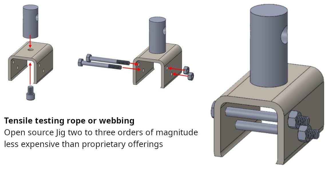
:Alternative food sources are essential in both low-resource settings and during emergencies like abrupt sunlight reduction scenarios. Seaweed presents a promising option but requires investigation into the viability of unconventionally sourced ropes for harvesting. In this regard, a low-cost reliable method to test the tensile strength of rope is needed to validate alternative materials for use in harvesting seaweed. Commercial rope testing jigs alone range in price from several thousand to tens of thousands of dollars, so there is interest in developing a lower-cost alternative. Addressing these needs, this article reports on an open-source design for tensile strength rope testing hardware. The hardware design focuses on using readily available parts that can be both sourced from a hardware store and manufactured with simple tools to provide the greatest geographic accessibility. The jig design, which can be fabricated for CAD 20, is two to three orders of magnitude less expensive than commercially available solutions. The jig was built and tested using a case study example investigating denim materials (of 1 5/8”, 3 1/4”, 4 7/8”, 6 1/2”, and 8 1/8” widths) as a potential alternative rope material for seaweed farming. Denim demonstrated strengths of up to 1.65 kN for the widest sample, and the jig demonstrated sufficient strength and stiffness for operations at forces below 4 kN. The results are discussed and areas for future improvements are outlined to adapt the device to other circumstances and increase the strength of materials that can be tested.
1. Introduction
To continue to provide food for the global population in abrupt sunlight reduction scenarios (ASRSs) such as nuclear wars [1,2], asteroid/comet impacts [3,4], and large volcanic eruptions [5,6], alternative food systems have been proposed [7,8]. This area of research, now known as resilient foods, has increased rapidly [9,10] with many systems focusing on ASRSs [11,12]. A combination of resilient foods could avoid mass starvation [7,8], but many are at the early stages of development and the ramp rates necessary are challenging during a disaster. A promising candidate resilient food that is appropriate for a low-technology setting and could be ramped up quickly [13] is algae [14] and seaweed [15,16]. Seaweed is an established human food [17]; the Food and Agriculture Organization of the United Nations has been encouraging seaweed production for many years and the seaweed industry has been growing [18]. Seaweed does not compete with land or freshwater and does not use pesticides [19]. Seaweed can maintain good yields in low-tech settings [15,16], and it may be resistant to high UV radiation levels, which is expected from ASRSs [20,21,22]. Remarkably, seaweed can meet all human protein needs [23] and globally 48 million km2 are suitable for seaweed production [24].
To enable low-cost geographically distributed low-tech seaweed harvesting, the primary input is rope [25,26]. In an ASRS, conventional commercial seaweed ropes [27] would not be in ready supply at the scale necessary to sufficiently ramp up seaweed production and thus alternatives would need to be sourced from local materials. Rope for this application must have sufficient tensile strength to support the algae growing on it and withstand sometimes severe external sea conditions [28]. The tensile strength of rope material has been under investigation for a long time [29]. Conventionally, tensile strength rope testing consists of a mechanical tester, which is commonly used worldwide, and a specialty jig for holding the rope [30]. Unfortunately, these jigs are not widely available, are often machine-specific or require a custom adapter and are expensive. Instron and ADMET are example suppliers for performance jigs and universal testing machines, and they produce grips for each niche sample shape, material, and strength. In terms of testing rope, cord, or yarn, Instron offers a variety of grips such as the Pneumatic Action Tire Cord Grips (10 kN, 5 mm diameter max) [31], Pneumatic Action Tire Cord and Yarn Grips (5 kN, 2 mm diameter max) [32], Wire Snubbing Grips (2.2 kN, 0.125 mm diameter max) [33], and the Webbing Capstan Grips (50 kN, 50.8 mm width max, 4.75 mm thickness max) [34]. These grips are highly specialized in terms of the sample shape and material they can test, with the majority being restricted to thin wire or rope and only the Webbing Capstan Grips capable of supporting strap testing. These grips are available with steep lead times and cost between CAD 3240 and 24,600 before considering the necessity of either a new tensile testing machine or an adapter. Thus, a low-cost reliable method to test the tensile strength of rope is needed.
To fill this research gap, this article reports on an open-source design of a tensile strength rope testing hardware. The novel hardware design focuses on using readily available parts that can be sourced from a hardware store or steel supplier and minimum machining to provide for the greatest geographic accessibility. The designs are fabricated and tested using a case study example that investigates denim material as a potential alternative rope material for seaweed farming during an ASRS when supplies are limited or to provide lower-cost sources of rope. The results are presented and discussed and areas for future improvements are outlined.
2. Design
Conducting tensile tests on fibrous materials including braided rope is associated with a series of challenges that are reflected in the design of this open-source jig. The primary design concern for any tensile rope tester is finding a method of securing the rope that eliminates any slip that might occur between the grips and individual fibers of the rope and webbing. To accurately represent elongation as the ability of a fiber to absorb energy, the jig must provide a way to engage all fibers simultaneously while avoiding local stress concentrations. Although there are many possible geometries that can be applied to test the tensile strength of rope, the design used in this study does not use a split drum, but instead secures the sample to a point offset from the axis of loading, before winding the rope between two drums on the axis of loading as outlined in ASTM D6775 [35]. This offers the advantage of distributing the load more evenly along the fibers of the rope and ensures the region of rope subjected solely to tension is not influenced by the fixturing method. Furthermore, by introducing the force in both a vertical (direction of tensile force) and horizontal (across the drums) component, the jig for the tensile tester can isolate the greatest amount of tensile force along the center of the material being tested.
The fixturing clamps and the drums of commercial rope testers are substituted for two ¼” shoulder bolts spanning a steel C-channel cut from welded square steel tube. The square tube is then bolted to a threaded round bar that provides the interface for mounting to a TTS Series Tensile Tester [36]. The first bolt acts as drum for a rope or webbed specimen to be wrapped around and the load distributed. The second bolt offers a fixturing location via a knot for rope, or a stitched loop for a webbed material. The complete jig consists of two mirrored halves and requires only six bolts, four ¼” standard nuts (optional), two 3” lengths of square tubing, and two 2 3/8” lengths of round bar. The materials necessary to manufacture both mirrored halves of this design were purchased for a total of CAD 19.81 before tax. This is the material cost, which does not include labor costs associated with machining and assembly, which will vary widely depending on location.
3. Build Instructions
3.1. Manufacturing
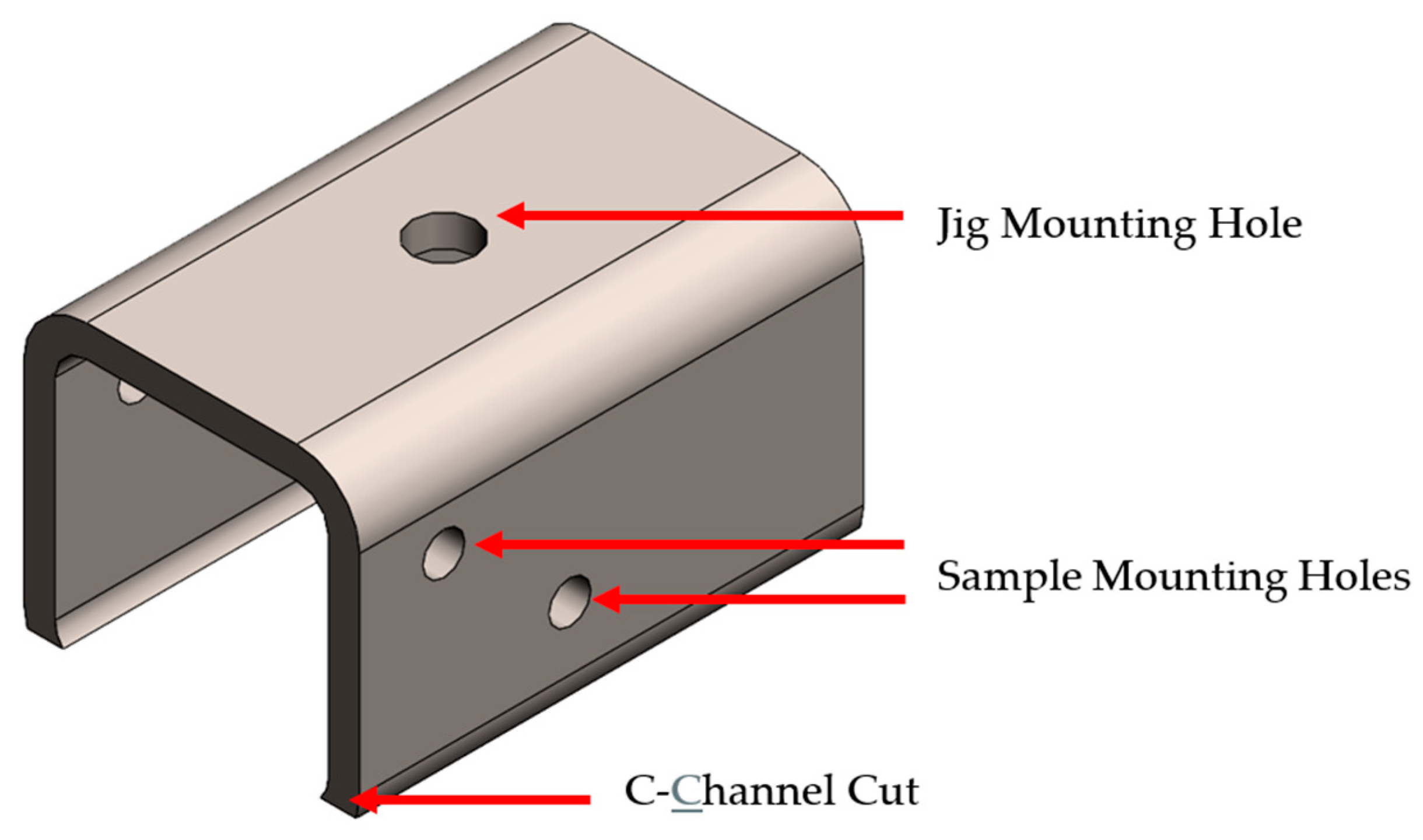
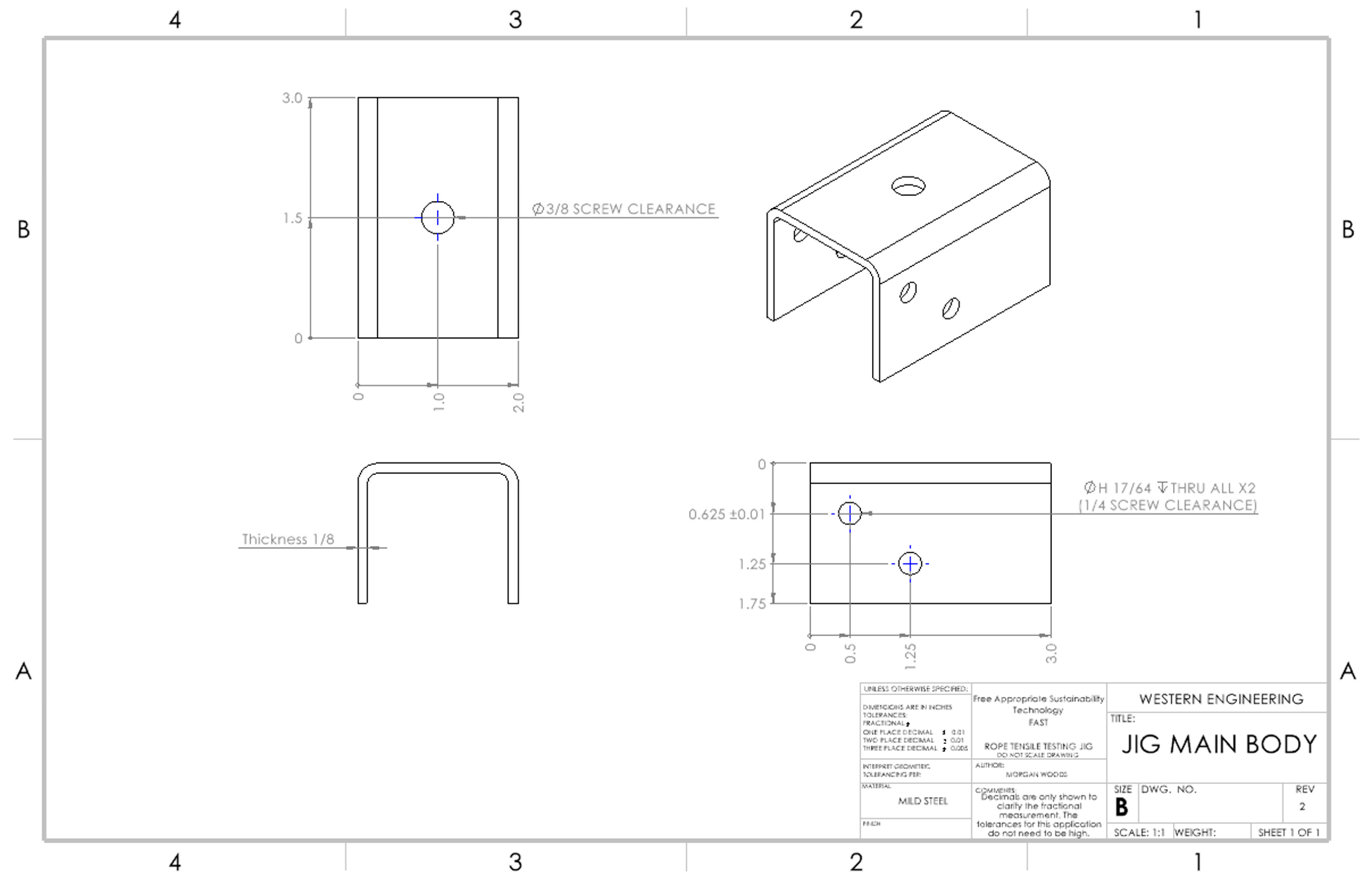
A total of four components must be machined to produce both mirrored halves of the jig. This involves a series of simple machining operations that must be used to produce the main jig body (Figure 1) followed by the jig mount (Figure 2). Detailed drawings for each part are shown in Appendix A. As can be seen in Figure 2, the jig mounting hole is in the middle of the top of the C channel. The lowest sample mounting hole is positioned on both sides of the C channel such that the material being tested is directly in line with the jig mounting hole. Thus, the force from the jig mount is directly transmitted to the material without distortion. The second sample mounting hole is positioned to one side of the C channel, as can be seen in Figure 2.
The main jig body was sourced from 2” square steel tubing and ordered as two pre-cut 3” lengths. A scribe was used to locate a point at the center of one of the flat faces in preparation for drilling the jig mounting hole. A hammer and steel punch were then used to indent the previously scribed point to assist in piloting the drill bit during machining and limit tool slip. The tube was next secured within a drill press and the 3/8” clearance jig mounting hole drilled. The two sample mounting holes were located, marked, and similarly punched on one of the adjacent faces relative to this first operation and adhering to the hole layout in Appendix A. The component was returned to the drill press and the fixture adjusted to ensure there was sufficient clearance to allow the drill bit to pass through both sides of the tubing to complete the through-all sample mounting holes. An H 17/64” drill bit was used to complete both holes. Once all holes were complete, a horizontal band saw was used to cut the remaining face opposite the 3/8” mounting hole off. The resulting part was approximately 1 ¾” in height, though this dimension is not critical. This operation is used to simply convert the square tubing into a C-channel (note that a C-channel can also be purchased, but due to material availability and tooling rigidity during drilling, a tube was used). It was critical to complete all drilling operations in advance of this final cut to prevent any bending or misalignment that could have occurred while drilling if the holes had not been supported on both sides. Once complete, a file and belt sander were used to deburr and break all sharp edges.
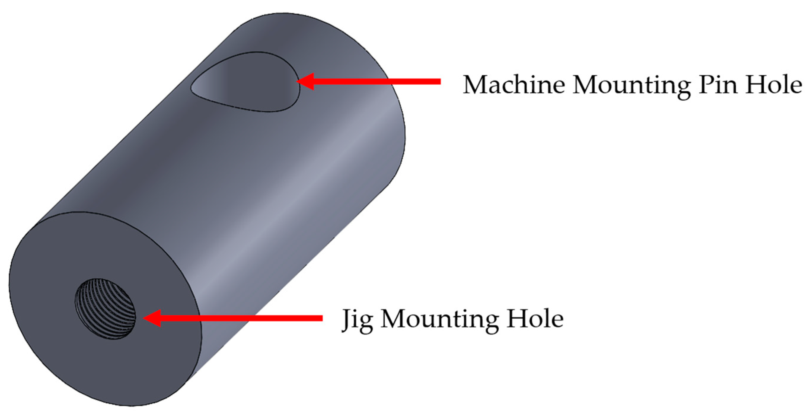
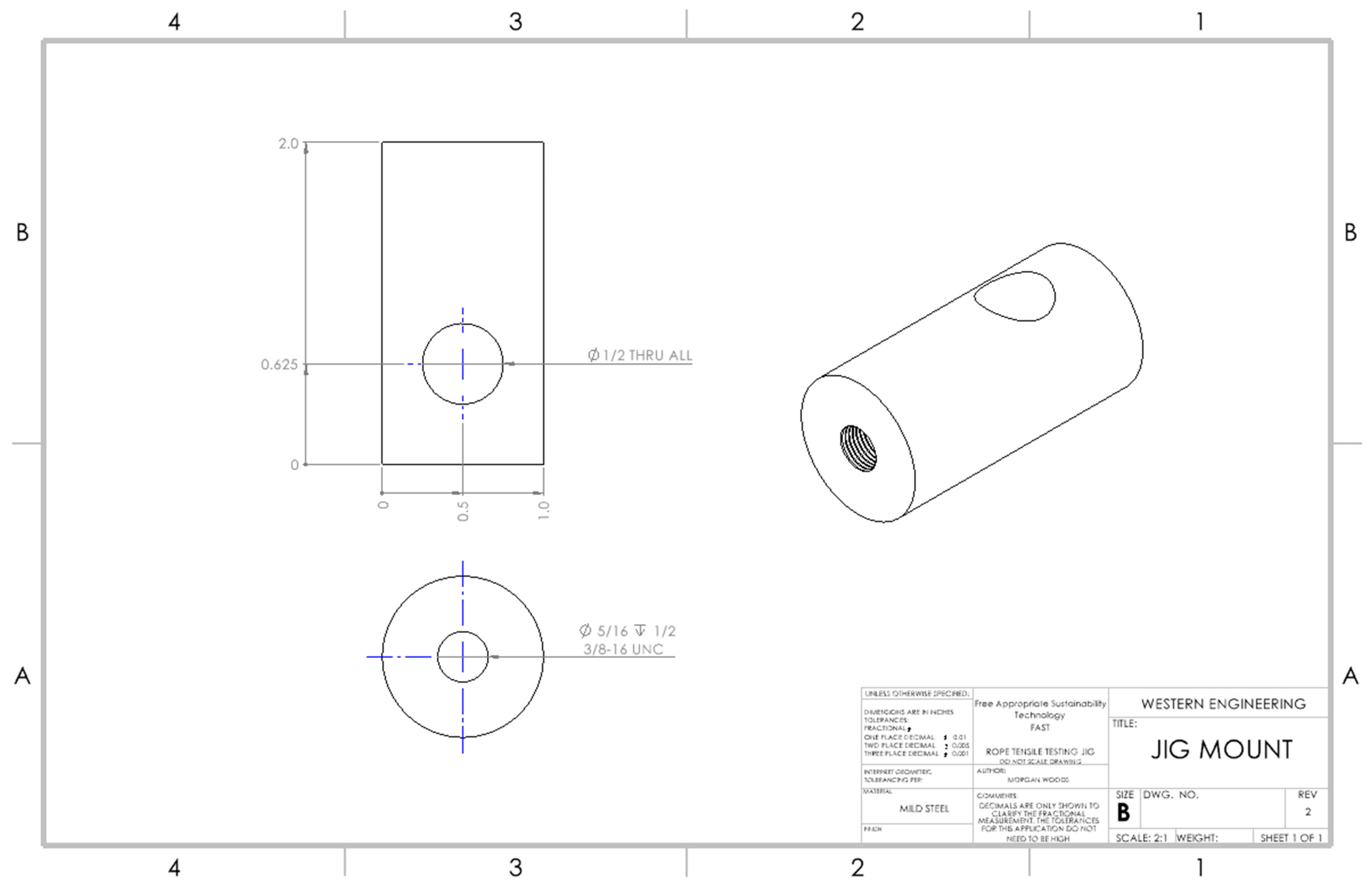
The jig mount was purchased to length from 1” mild steel round bar. The 2” length stock was fixtured in a CNC using a 3-point diameter jig with the length biased along the X direction. An edge finder was used to locate two tangent points on opposite sides of the circumference to datum the centerline along Y, and one point on the flat end of the bar to datum the X direction. A ½” end mill was used to machine away a shallow section of the circumference to provide a flat surface for locating and drilling the machine mounting pin hole. The end mill was then replaced with a 1/2” drill bit and the through-all hole machined at 5/8” from the bar end to the hole center. This operation could have also been completed using an angle grinder to prime the flat surface, and a handheld drill or drill press used to complete the hole at the expense of reduced accuracy. The round bar was then relocated to a lathe to drill the blind hole on the flat end of the bar for the jig mounting hole. A 5/16” drill bit was used to complete this pilot hole as is required to match the subsequent 3/8”-16 coarse tap. This operation could have alternatively been performed using a drill press, though a lathe is recommended for ease of alignment. Once the jig mounting hole had been piloted, the part was removed from the lathe and a 3/8”-16 hand tap used to thread the hole. Should a lathe or tap set have been inaccessible, a welder can be used to achieve this connection without a tap between the main jig body and jig mount.
3.2. Assembly
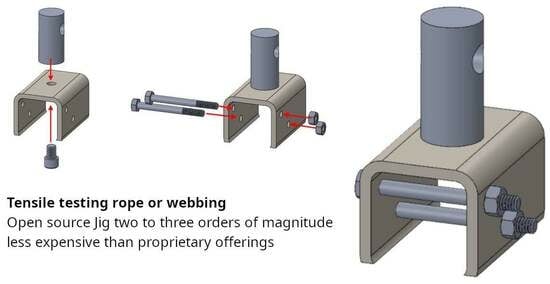
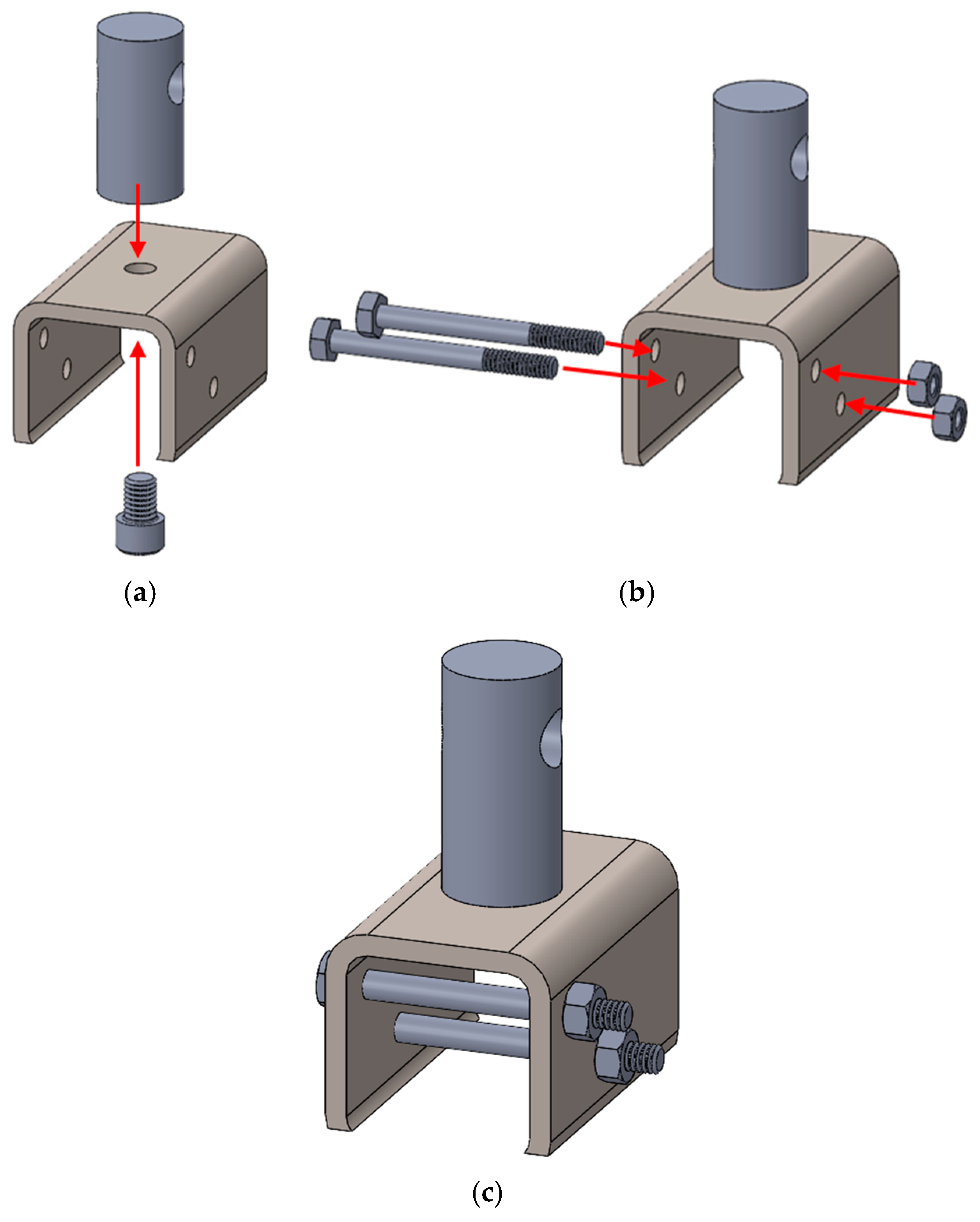
To assemble one half of the open-source rope tensile testing jig, align the jig mount and main jig body along the jig mounting hole. Thread a 3/8”-24 × 1/2”-long socket head cap screw through the main jig body and into the jig mount, as shown in Figure 3a. Ensure the axis of the machine mounting pin hole on the side of the jig mount is parallel to the sample mounting holes once tight. The use of a threaded hole on the jig mount to assemble the jig ensures a repeatable connection point with the tensile testing machine that can be applied to an array of other applications. The main jig body can be replaced by other open-source jigs designed to target other applications requiring different fixturing features.
A shoulder bolt was fed through each of the sample mounting holes and secured with a nut. These bolts undergo repeated removal and reassembly while interacting with the sample materials.
3.3. Open-Source Design License
To ensure that the design can be used as widely as possible, the design has been released under an open hardware license (CERN OHL-S v2) and the documentation has been released under GNU GPL v3.
4. Operating Instructions
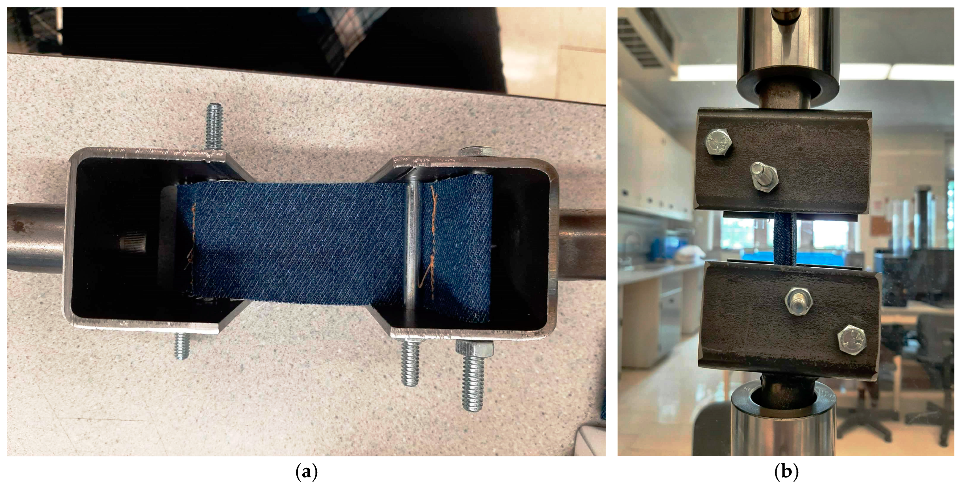
A TTS Series Tensile Tester with a loading capacity of 25 kN was used to conduct the tensile tests on all samples. To begin each test, the sample was first loaded onto the open-source rope tensile testing jig outside of the machine. To do this, a stitched loop of the sample (denim tested here) or clove hitch knot (for any type of rope) was tied to the sample mounting bolt closest to the jig mount. The sample was then laid over the second sample mounting bolt before being fed to the mirrored jig. This procedure was repeated for the second half of the jig, as shown in Figure 4. It is important to note the position of the sample mounting bolts from each jig half relative to their complement on the opposite side. To ensure an equal loading case on both sides of the sample, the sample mounting bolts are mirrored diagonally across the sample and the center bolts contact opposite sides of the material.
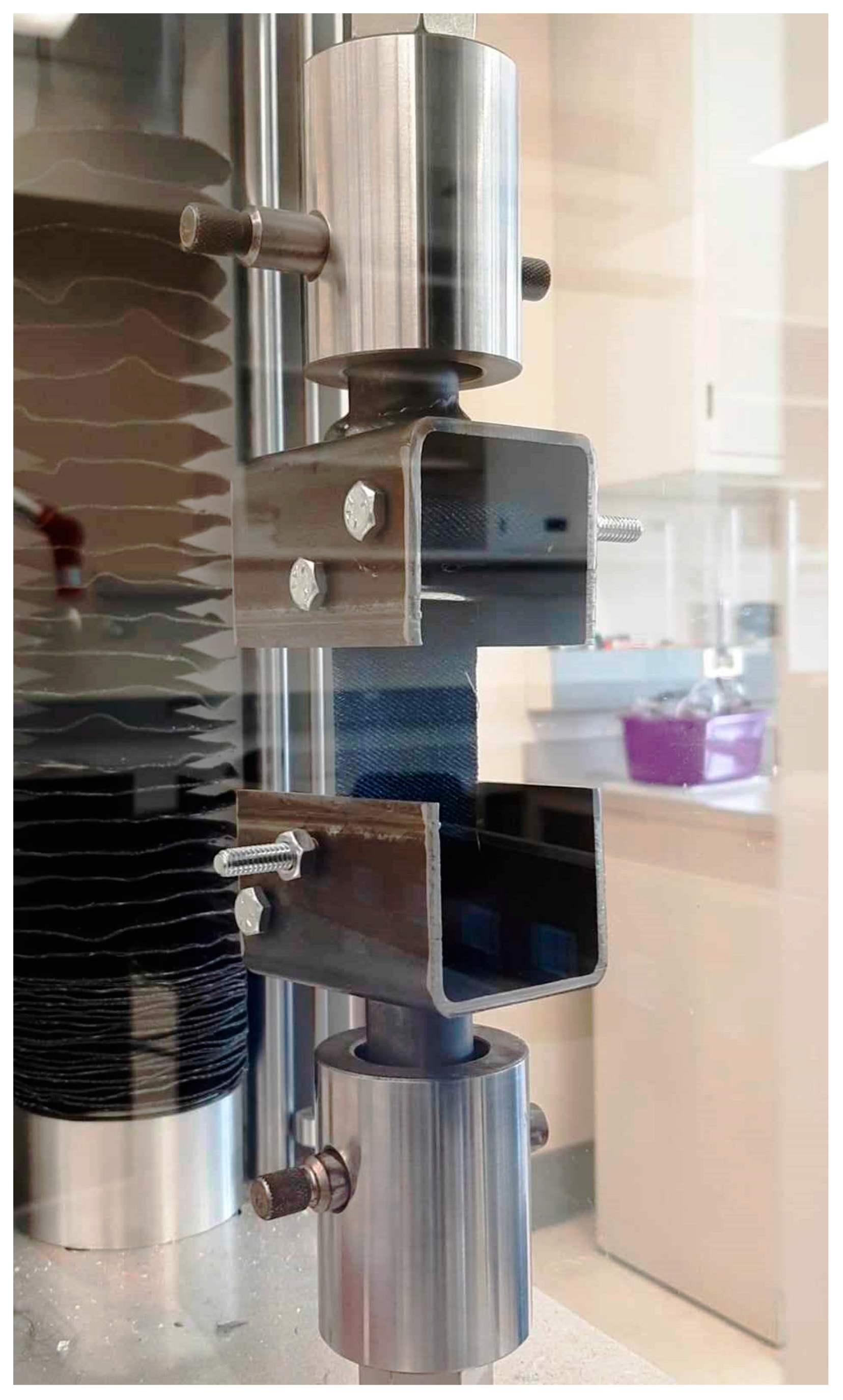
Once the sample was loaded, the safety doors on the machine were opened and the machine mounting pin removed from the upper and lower chuck. One half of the open-source rope tensile tester was inserted into the upper chuck and the pin fed back through the chuck and jig. Once secured, the doors were closed, the machine safeties reset, and the moveable work head manually jogged down until the lower jig mount was in position in the lower chuck. The doors were opened and the machine pin fed through the lower chuck and jig. A loaded sample is shown in Figure 5.
Once the sample was loaded, the machine doors closed, and all machine safeties reset, a tensile test could be performed. On the user interface, the machine pull rate was set to 0.5 mm/s and the x-axis sampling boundary modified to accommodate a conservative 100 mm to avoid losing data. Each test was initialized by first manually jogging the machine up to eliminate any excess slack in the sample, before zeroing the transducer reading at this starting position and beginning the test.
Once a tensile test was complete, all data were saved, exported, and edited to adjust the starting point of the elongation recorded to match the lowest recorded force reading. To achieve this, the elongation corresponding to this first positive force reading was subtracted from all subsequent elongations to manually ensure a zero start.
5. Validation
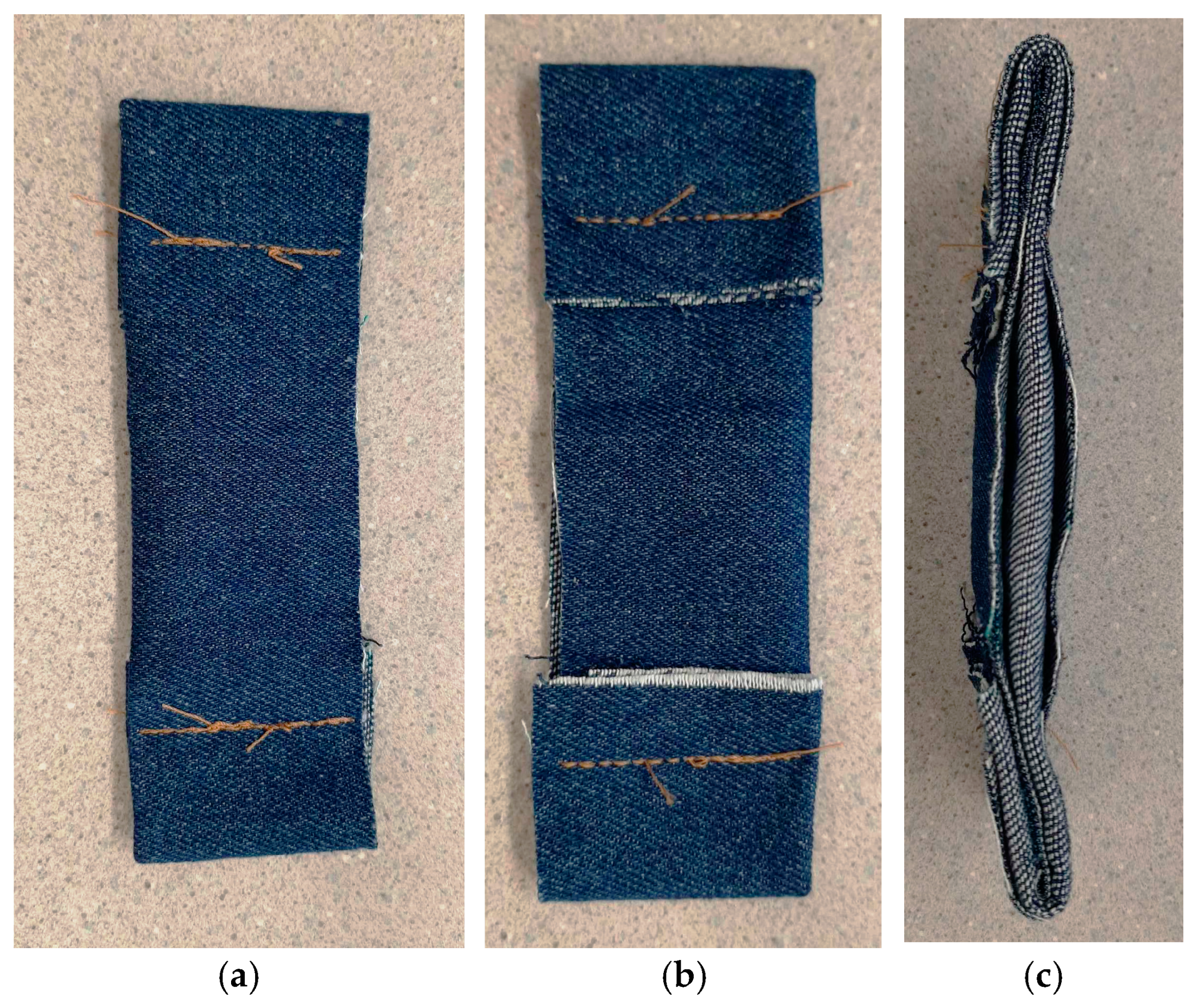
To evaluate the performance of the new hardware, tensile tests were performed on denim to determine if it is a viable alternative roping material for applications in seaweed production in an ASRS and demonstrate that the hardware can be used effectively for both rope and webbing. Due to the fibrous nature of denim as a woven fabric, it presented an additional obstacle to testing. The clove hitch knot used for testing conventional rope materials could not be used to secure the denim material as it would introduce unwanted stress in the fabric and result in an uneven distribution of loading along the fibers. As a result, the material was cut to a standard control width (1 5/8”) that matched the maximum width of material that could be fit along the mounting bolt within the tubing without introducing any folds or wrinkles. While these specimens would normally be clamped, this jig specifically intends for the material to be sewn or knotted to the fixture point to better reflect how the material will be used (i.e., scrap lengths sewn or tied together) as well as reducing the complexity of the jig by eliminating the moving parts of a clamp. Segments of material were cut in 8” lengths before being looped back at each end and stitched to yield samples with end-to-end 5” lengths. The sample lengths were chosen based on halving the ASTM D6775 standard due to substantial stretching of fibers. These loops were secured using Gütterman No. 0.5 professional jean thread suitable for securing medium- to heavy-weight denim to reduce the likelihood of their failure prior to the denim. Care was also taken to ensure the stitches were sealed at the ends by reversing over the start and finish of each seam. The resulting samples can be seen in Figure 6.
To increase the width of the denim used, the sample widths were incrementally increased by the standard control width between tests to yield samples with 1 5/8”, 3 1/4”, 4 7/8”, 6 1/2”, and 8 1/8” widths. The cut-off sample width of 8 1/8” was chosen based on an approximation of the average pant leg width that could be easily acquired during an emergency. With each standard width added, an additional fold was required. An accordion style of folding was adopted to maximize the fibers engaged and ensure a consistent spanning width. Once folded, the material was folded over and stitched down to create the mounting loop. The result of this folding can be seen in Figure 6c.
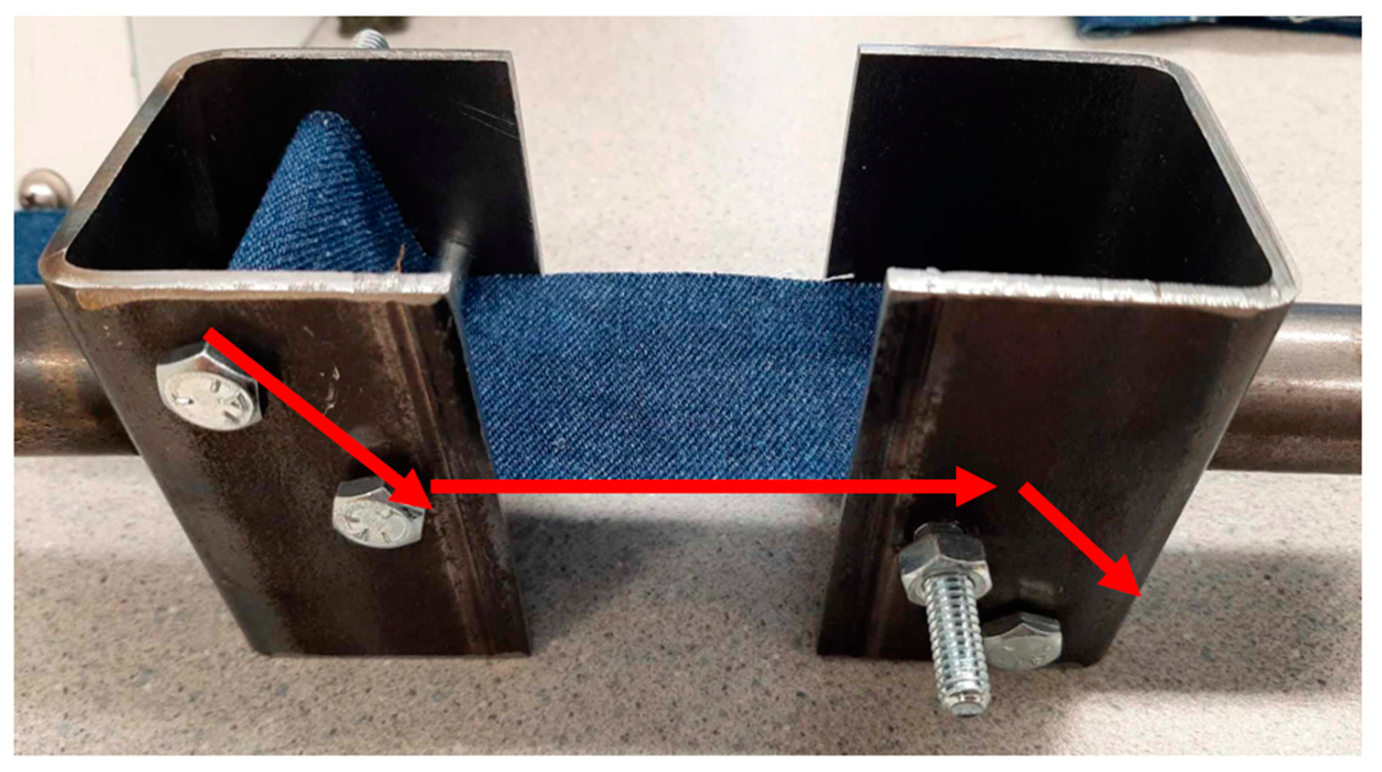
To load each sample, the bolt on the main jig body closest to the jig mount must be removed and passed through the stitched loop on the sample. The sample must then be fed between the backing of the main jig body and the second bolt to allow the loading to be distributed across the fabric in contact with the guide bolt. When connecting the sample to the other half of the jig, the bolt pattern must be diagonally mirrored, as shown in Figure 7, in accordance with ASTM D6775 to engage both sides of the webbed specimen. The sample must be connected diagonally across the jigs so that each guide bolt is contacting a different side of the material.
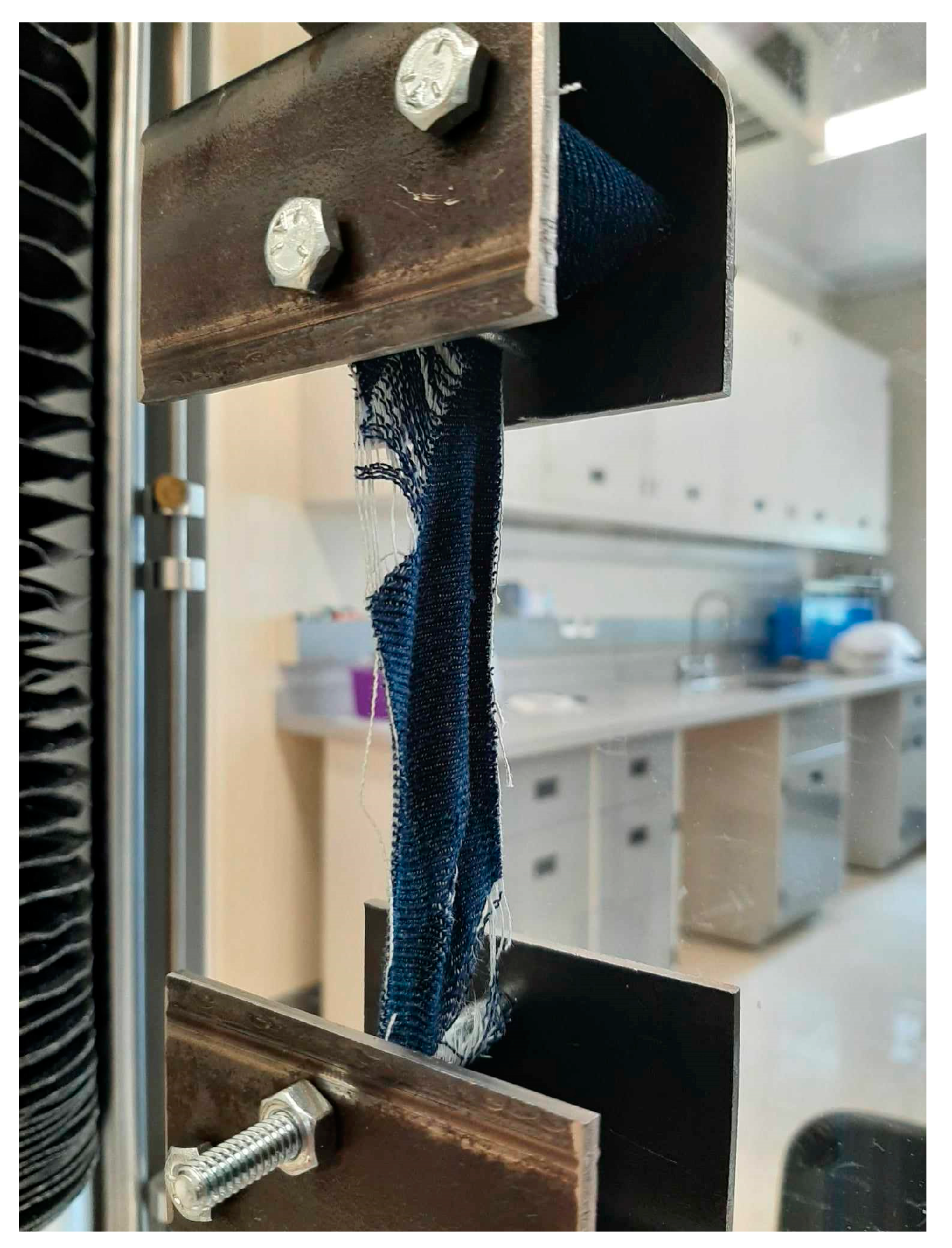
Once secured, the jigs can be mounted within the tensile testing machine and secured with the mounting pin through the hole in the jig mount. The tensile tests were conducted at a rate reduced from ASTM D6775 to accommodate the fixturing method and reduce the likelihood of abrupt tearing at the stitches. A pull rate of 0.5 mm/s was used until failure was detected by the machine or a significant drop in the applied force was observed. The sample appearance upon failure is shown in Figure 8.
5.1. Results
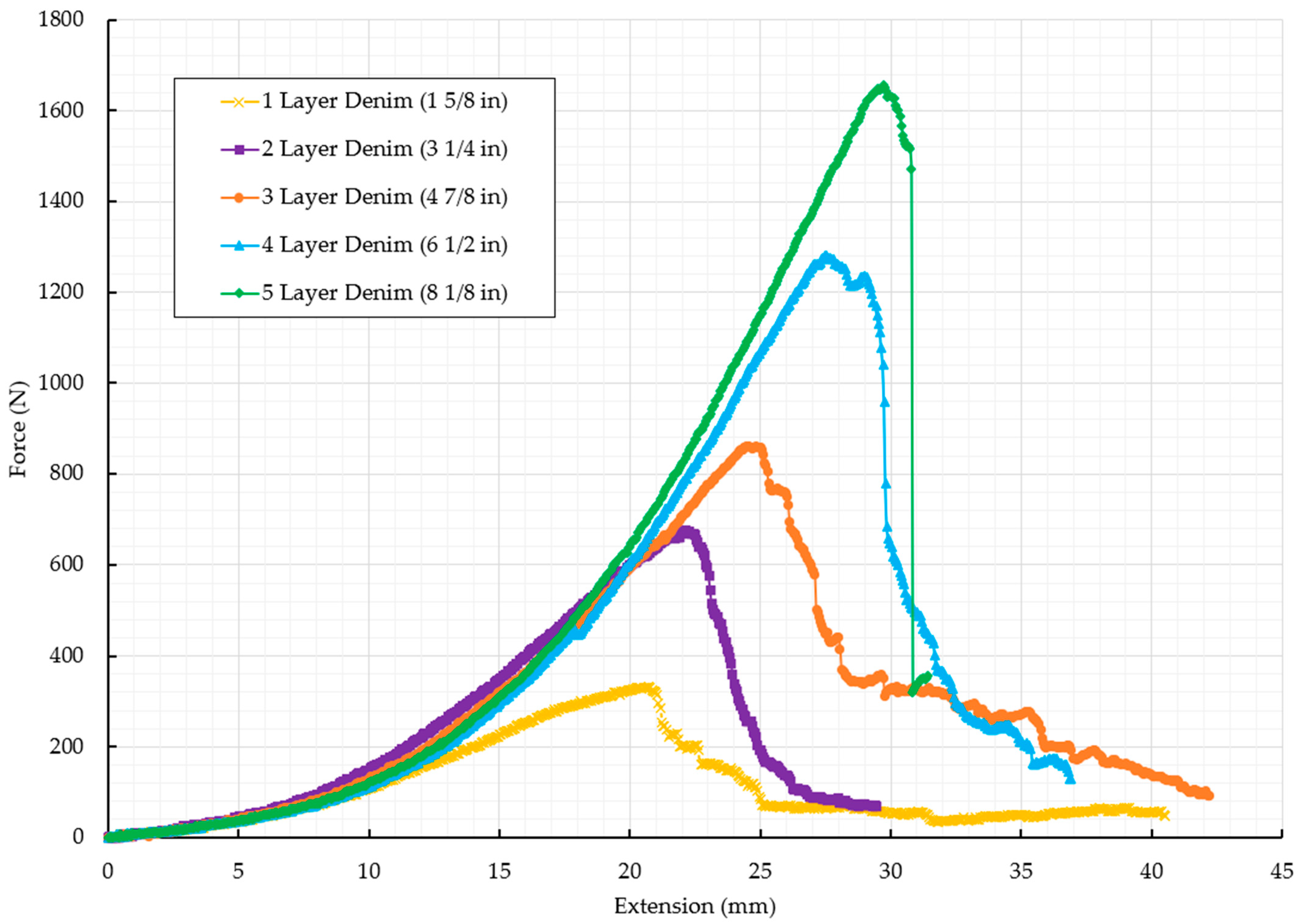
The denim samples yielded a visible trend of increasing tensile strength and stiffness proportional to the thickness of the material used. For each sample tested, the overall strength increased by an increment approximately consistent with the tensile strength for one standard control width of denim. The force vs. elongation of the samples is summarized in Figure 9.
Rigid specimens were expected to produce double the force at the same elongation, and it is presumed that the samples would fail at the same elongation. In this case, similar forces are observed with the same elongation at the beginning because the samples are flattening out the accordion running around the bolts. Then, as the multi-layer samples require a lot of flattening, they fail at a greater elongation. It is important to note that all samples excluding the 8 1/2” width failed along the center between the guide bolts and did not demonstrate substantial deformation at the location of stitching. This supports the use of stitched loops in place of clove hitch knots at no expense to overall strength. The exception, with the 8 ½” sample, was the failure of the thread along the stitched loop at the maximum loading case and not the denim. This would suggest the material has additional loading capabilities not demonstrated in this final test, highlighting the need for additional testing in future work. The maximum tensile loading cases are summarized in Table 3.
5.2. Assessment of Jig Performance
Conducting tensile test studies on rope and belt samples is traditionally an expensive and challenging investigation. The jig used in this study provided an effective, accessible, and inexpensive alternative to those put forward in the limited existing methods. The performance quality of the jig design was demonstrated by the consistency of the denim results both in the failure mode observed and the consistent trend in ultimate tensile strength. Each test yielded a failure point within the gauge length of the sample and far from the guide bolts. This failure location supports both the sewn loop mounting method chosen and the use of guide bolts to distribute the tensile force more evenly across the complete sample width and spread of fibers. Furthermore, repeated tensile tests on the same thickness of denim demonstrated consistent ultimate tensile strength results, and a visible trend of increasing stiffness and strength associated with additional sample width (and number of fibers) of the denim samples is observed. The ability to capture these results in both a predictable and consistent manner supports the performance of the jig designed. Therefore, using denim as the testing material allowed the jig to demonstrate sufficient strength and stiffness for operating at forces of at least 1.65 kN. In routine testing using a similar stitched loop mounting method on webbing and belt materials with industrial thread, the jig also demonstrated a loading accuracy of up to 4 kN, at which point the stitching was once again the critical point of failure.
In terms of user experience, the samples were easy to load into the jig using the sewn loop mounting method, and the jig was likewise easy to load into the tensile testing machine. The complete operation required only the removal and replacement of one bolt on both the upper and lower jig, and one pin on the upper and lower mounting connection within the tensile testing machine. The complete procedure of loading both the sample and jig took under a minute, in which most of the time is associated with manually jogging the tensile testing machine.
Furthermore, the simplicity of this design ensures the jig can easily interface with any machine through the simple replacement or tailoring of the jig mount. This eliminates the need to purchase additional equipment or adapters. The use of readily accessible steel stock, mounting hardware, and simple machining operations ensures the jig can be reproduced virtually anywhere and by any skill set. This component selection also played a substantial role in cost, allowing the pair of upper and lower jig halves to cost 0.1% of the nearest industry alternative (Instron Capstan Webbing Grips at CAD 20,500) with virtually no lead time. These more expensive commercial jigs often rely on winding the sample around a drum and clamping or tying the ends to secure it. While effective, this requires a more involved and expensive system design. To combat this and reduce the overall cost, the sewn loop mounting method for belts and webbing was used at the expense of introducing the thread strength as the new limitation on jig strength. For these tests, the upholstery thread used caused the failure point to transition from the gauge length of the sample to the stitching above 1500 N, as seen in the 8 1/8” sample. This feature acted as the primary drawback for this jig design and associates the limit on belts and webbing that can be tested with the strength of the stitch. Alternatively, ropes that can be secured using a clove hitch knot around the off-axis mounting bolt allow the jig to be tested in substantially higher loading cases.
5.3. Assessment of Denim Performance
The hardware was evaluated to determine if denim could be used in place of nylon rope for seaweed cultivation. The results indicate that commercial denim could be tailored to offer the necessary material properties if it were rolled or folded as observed in these trials. To feasibly achieve the appropriate rope length, multiple pairs of pants could be sourced from any variety of retailers, both used and new, separated into their front and rear panels, and either tied or sewn together. This improved rope could be further reinforced by not only accordion folding or rolling each swath of fabric but also by adding additional reinforcing stitches and surging or burning the edges to combat fraying. The values found in Table 3 can be compared to tables of standard nylon rope strengths [37]. Safety factors would need to be selected for this application after some experimental testing of denim in the field. For example, the Engineering Toolbox uses 12, so a ¼ inch (6 mm) nylon rope has a minimum breaking strength of 6.61 kN but a safe load of 551 N [37]. Thus, with this safety factor, only the thickest denim material tested would be usable for the replacement of ¼ inch nylon ropes for small-scale seaweed production. In more extreme circumstances [16], where the safety factor might need to be omitted, any denim except the thinnest tested (Table 3) would be adequate. It is clear that, for this particular application, future work will need to be performed under real-world testing conditions to determine an appropriate safety factor. While this study was based on incremental modification of the appropriate ASTM standards to better reflect the application in terms of the fixturing method, there is substantial opportunity to extend this study. While standards demand dry materials, a more appropriate testing apparatus would utilize saturated materials to better reflect a seaweed-cultivating environment.
5.4. Future Work
ASTM Standard D6775 outlines an optimal jig design for testing the breaking strength and elongation of textile webbing, tape, and braided materials. This standard calls for a split-drum-type upper and lower clamp to achieve uniform loading across the material. Each half of the clamp involves a drum split into two adjustable halves, which the operator can clamp the specimen between before winding the material around the outside of the drum and toward the other set of jaws. To ensure all fibers are engaged evenly, the upper clamp is loaded to face the back of the tensile tester while the lower clamp is loaded to face the front. This mirrored “diagonal” positioning allows the winding direction to reverse between the upper and lower clamps, allowing both halves to engage and contact opposite sides of the specimen. The standard also specifies sample characteristics falling within a maximum width of 3.5 in (90 mm), a gauge length of 250 mm ±10 mm (10 in ±0.5 in), and a failure strength below 89,000 N. For apparatus preparation, the specimen must be free of folds parallel to the direction of loading subjected to a pull rate of 1.25 mm/s. The design adopted in this paper was developed by tailoring ASTM standard D6775 and taking inspiration from alternative commercial products and studies such as the braided rope tensile testing jig explored but not commercialized by the Instron Applications engineering lab [30], as well as the discontinued ASTM standard D4268 wrap grips [38].
The primary advantage of this novel hardware is its low cost, which is two to three orders of magnitude below those of commercial offerings. The hardware designed and manufactured here was adequate for testing the denim material target but would need to be scaled up to match the capacities of commercial jigs. This demonstrates the additional advantage of being able to easily manufacture a jig with the appropriate strength for the application of interest. This hardware presents such simplicity in design that it ensures users can easily replicate and modify it to suit their specific application. By only increasing or decreasing the wall thickness of the tubing and shoulder bolt diameters (drums), the testing jig can easily be scaled up or down, respectively, for applications with a known intended loading. This allows the user to only invest as much as they need in metal supply instead of spending in excess on a jig that has capabilities vastly exceeding their actual requirements. It is also noteworthy that the more the hardware is scaled up and the larger the drum bolt used, the more even the distribution of load will be across the material and the lower the likelihood of encountering any potentially high-stress concentrations.
One of the challenges of testing flexible multi-strip materials as demonstrated here is that they could not be inexpensively clamped without introducing a risk of slipping, inconsistently loading the fibers, or reducing the accuracy so they were stitched together instead. The novel hardware developed here has been shown to be adequate for testing stitched flexible materials that can withstand forces below 1.65 kN with denim-grade thread and below 4 kN with higher-strength industrial thread. This is, however, a relatively low value for marine ropes of larger diameters. Additional readily available materials and fabrics such as canvas, burlap, corduroy, or even scrapped seat belts could be tested to expand or rule out alternative options for seaweed cultivation. To test stronger and thicker materials, the open hardware design developed here can be scaled up. As the hardware is scaled, the capacity for scaling tests will eventually be limited by the tensile testing machine itself. These improvements can be tested in future work on rated ropes or straps to confirm the accuracy of the device.
Finally, it should be noted that the development of inexpensive open-source jigs emphasizes the need for an easily replicable and validated high-strength open-source universal mechanical tester. The open-source jig tested here could be adapted to work with several open-source universal mechanical testers, such as (i) a small tester developed by the YouTuber Curious Scientist with geared stepper twin screws but no rating for strength [39]; (ii) CNC Kitchen’s wood device, which follows a similar approach and can reach a 2.5 kN coupling limit, at which point it begins to slip [40]; (iii) the TestrBot, which uses a linear design, but can only reach 0.9 kN [41]; (iv) CrazyBlackStone version 2, which used the same approach as the TestrBot and was tested up to 1 kN [42]; and (v) a Hoffmann Tactical design, which uses a direct stepper and linear slide to reach 2 kN because of the motor limit [43]. However, these maker-type machines do not offer the high strength capabilities of commercial machines and, in some cases, lack both documentation and validation. In the peer-reviewed literature, there is (i) the Freeloader, which can reach 5 kN [44] and has documentation [45]; (ii) a University of Toronto system, which needs to be fully characterized [46]; (iii) the Jönköping University thesis system, which is able to reach 10 kN [47], and (iv) a Materiom UTM on GitHub, which remains under development [48]. However, none of these systems have obtained widespread use because they do not adhere to the best practices for general design of free and open-source hardware for scientific equipment [49], which demands the systems be easy to build. They are all over-complicated and rely on high-cost materials or significant machining, which is not available at accessible prices in many parts of the world. A system is needed that can use off-the-shelf parts with minimal machining such as the hardware fabricated and tested in this study. As much as possible, these systems should rely on digital fabrication to take advantage of the open-source RepRap principles [50,51,52].
6. Conclusions
Continued food-sourcing challenges faced in low-resource settings and the potential of ASRSs encourage investigation and validation of alternative foods and associated harvesting methods. Seaweed and the existing methods of growth and harvesting it via nylon rope present a viable solution to these food shortage scenarios. However, to ensure seaweed harvesting is accessible and inexpensive, alternative ropes using commonplace materials to substitute the nylon standard are required. In suggesting alternative ropes, the strength of each material must be validated using a universal testing machine and associated jig, which presents a substantial financial barrier. To overcome that barrier, in this study, an open-source tensile testing jig was designed and manufactured to inexpensively test any variety of belts, webbing, and rope. The jig was validated using denim material as the primary case study, which proved strong enough to replace some low gauges of nylon rope with tensile strengths below 1.65 kN depending on the safety factors tolerated for a given application. The jig design, which can be fabricated for CAD 20, represents a more than two to three orders of magnitude reduction in cost relative to commercially available jigs. The jig demonstrated sufficient strength and stiffness for operating at forces below 4 kN. Future improvement works should be aimed at adapting the device to higher-strength materials, testing a wider variety of potential nylon rope substitutes, and coupling it to an open-source universal testing machine.
Author Contributions
Conceptualization, J.M.P.; methodology, M.C.W. and N.N.; validation, M.C.W. and N.N.; formal analysis, M.C.W. and N.N.; investigation, M.C.W. and N.N.; resources, J.M.P.; data curation, M.C.W. and J.M.P.; writing—original draft preparation, M.C.W., N.N. and J.M.P.; writing—review and editing, M.C.W., N.N. and J.M.P.; visualization, M.C.W. and N.N.; supervision, J.M.P.; project administration, J.M.P.; funding acquisition, J.M.P. All authors have read and agreed to the published version of the manuscript.
Funding
Funding for this work was provided by the Future Fund and the Thompson Endowment.
Institutional Review Board Statement
Not applicable.
Informed Consent Statement
Not applicable.
Data Availability Statement
Data are available at https://osf.io/268ma (accessed on 1 January 2024).
Acknowledgments
The authors would like to thank David Denkenberger for helpful discussions, Mesfin Gebreyes for providing access to his tensile testing equipment and expertise, and Duane Jacques for providing material and machine shop support during fabrication.
Conflicts of Interest
The authors declare no conflicts of interest.
Appendix A
Figure A1.
Drawing of main jig body for open-source rope tensile testing jig.

Figure A2.
Drawing of jig mount for open-source rope tensile testing jig.

References
- Toon, O.B.; Robock, A.; Turco, R.P. Environmental Consequences of Nuclear War. Phys. Today 2008, 61, 37–42. [Google Scholar] [CrossRef]
- Coupe, J.; Bardeen, C.G.; Robock, A.; Toon, O.B. Nuclear Winter Responses to Nuclear War Between the United States and Russia in the Whole Atmosphere Community Climate Model Version 4 and the Goddard Institute for Space Studies ModelE. J. Geophys. Res. Atmos. 2019, 124, 8522–8543. [Google Scholar] [CrossRef]
- Chapman, C.R.; Morrison, D. Impacts on the Earth by Asteroids and Comets: Assessing the Hazard. Nature 1994, 367, 33–40. [Google Scholar] [CrossRef]
- Tabor, C.R.; Bardeen, C.G.; Otto-Bliesner, B.L.; Garcia, R.R.; Toon, O.B. Causes and Climatic Consequences of the Impact Winter at the Cretaceous-Paleogene Boundary. Geophys. Res. Lett. 2020, 47, e60121. [Google Scholar] [CrossRef]
- Rampino, M.R. Supereruptions as a Threat to Civilizations on Earth-like Planets. Icarus 2002, 156, 562–569. [Google Scholar] [CrossRef]
- Rougier, J.; Sparks, R.S.J.; Cashman, K.V.; Brown, S.K. The Global Magnitude–Frequency Relationship for Large Explosive Volcanic Eruptions. Earth Planet. Sci. Lett. 2018, 482, 621–629. [Google Scholar] [CrossRef]
- Denkenberger, D.; Pearce, J.M. Feeding Everyone No Matter What: Managing Food Security after Global Catastrophe; Academic Press: London, UK, 2015. [Google Scholar]
- Denkenberger, D.C.; Pearce, J.M. Feeding Everyone: Solving the Food Crisis in Event of Global Catastrophes That Kill Crops or Obscure the Sun. Futures 2015, 72, 57–68. [Google Scholar] [CrossRef]
- Tzachor, A.; Richards, C.E.; Holt, L. Future Foods for Risk-Resilient Diets. Nat. Food 2021, 2, 326–329. [Google Scholar] [CrossRef]
- Winstead, D.J.; Jacobson, M.G. Food Resilience in a Dark Catastrophe: A New Way of Looking at Tropical Wild Edible Plants. Ambio 2022, 51, 1949–1962. [Google Scholar] [CrossRef] [PubMed]
- Denkenberger, D.C.; Cole, D.D.; Abdelkhaliq, M.; Griswold, M.; Hundley, A.B.; Pearce, J.M. Feeding Everyone If the Sun Is Obscured and Industry Is Disabled. Int. J. Disaster Risk Reduct. 2017, 21, 284–290. [Google Scholar] [CrossRef]
- Denkenberger, D.; Pearce, J.; Taylor, A.R.; Black, R. Food without Sun: Price and Life-Saving Potential. Foresight 2018, 21, 118–129. [Google Scholar] [CrossRef]
- Bjerregaard, R.; Valderrama, D.; Radulovich, R.; Diana, J.; Capron, M.; Mckinnie, C.A.; Cedric, M.; Hopkins, K.; Yarish, C.; Goudey, C.; et al. Seaweed Aquaculture for Food Security, Income Generation and Environmental Health in Tropical Developing Countries. Available online: https://documents.worldbank.org/en/publication/documents-reports/documentdetail/947831469090666344/Seaweed-aquaculture-for-food-security-income-generation-and-environmental-health-in-Tropical-Developing-Countries (accessed on 1 September 2023).
- John, R.P.; Anisha, G.S.; Nampoothiri, K.M.; Pandey, A. Micro and Macroalgal Biomass: A Renewable Source for Bioethanol. Bioresour. Technol. 2011, 102, 186–193. [Google Scholar] [CrossRef] [PubMed]
- Jehn, F.U.; Dingal, F.J.; Mill, A.; Harrison, C.S.; Ilin, E.; Roleda, M.Y.; James, S.C.; Denkenberger, D.C. Seaweed as a Resilient Food Solution after a Nuclear War. Earth’s Future 2023, 12, e2023EF003710. [Google Scholar] [CrossRef]
- Mill, A.; Harrison, C.S.; James, S.; Shah, S.; Fist, T.; Alvarado, K.A.; Taylor, A.R. Preventing Global Famine in Case of Sun-Blocking Scenarios: Seaweed as an Alternative Food Source. In Proceedings of the 2019 Effective Altruism Global, London, UK, 18–20 October 2019. [Google Scholar]
- Mouritsen, O.G.; Dawczynski, C.; Duelund, L.; Jahreis, G.; Vetter, W.; Schröder, M. On the Human Consumption of the Red Seaweed Dulse (Palmaria Palmata (L.) Weber & Mohr). J. Appl. Phycol. 2013, 25, 1777–1791. [Google Scholar] [CrossRef]
- Priyadarshini, A.; Priyadarshini, A.; Rajauria, G. Economic Status of Seaweed: Production, Consumption, Commercial Applications, Hazards, and Legislations. In Recent Advances in Micro and Macroalgal Processing; John Wiley & Sons, Ltd.: Hoboken, NJ, USA, 2021; pp. 604–616. ISBN 978-1-119-54265-0. [Google Scholar]
- Fedoroff, N.V.; Battisti, D.S.; Beachy, R.N.; Cooper, P.J.M.; Fischhoff, D.A.; Hodges, C.N.; Knauf, V.C.; Lobell, D.; Mazur, B.J.; Molden, D.; et al. Radically Rethinking Agriculture for the 21st Century. Science 2010, 327, 833–834. [Google Scholar] [CrossRef]
- Mills, M.J.; Toon, O.B.; Turco, R.P.; Kinnison, D.E.; Garcia, R.R. Massive Global Ozone Loss Predicted Following Regional Nuclear Conflict. Proc. Natl. Acad. Sci. USA 2008, 105, 5307–5312. [Google Scholar] [CrossRef]
- Xu, L.; Wei, K.; Wu, X.; Smyshlyaev, S.P.; Chen, W.; Galin, V.Y. The Effect of Super Volcanic Eruptions on Ozone Depletion in a Chemistry-Climate Model. Adv. Atmos. Sci. 2019, 36, 823–836. [Google Scholar] [CrossRef]
- Bardeen, C.G.; Kinnison, D.E.; Toon, O.B.; Mills, M.J.; Vitt, F.; Xia, L.; Jägermeyr, J.; Lovenduski, N.S.; Scherrer, K.J.N.; Clyne, M.; et al. Extreme Ozone Loss Following Nuclear War Results in Enhanced Surface Ultraviolet Radiation. J. Geophys. Res. Atmos. 2021, 126, e2021JD035079. [Google Scholar] [CrossRef]
- Greene, C.H.; Scott-Buechler, C.M.; Hausner, A.L.P.; Johnson, Z.I.; Lei, X.G.; Huntley, M.E. Transforming the Future of Marine Aquaculture: A Circular Economy Approach. Oceanography 2022, 35, 26–34. [Google Scholar] [CrossRef]
- Froehlich, H.E.; Afflerbach, J.C.; Frazier, M.; Halpern, B.S. Blue Growth Potential to Mitigate Climate Change through Seaweed Offsetting. Curr. Biol. 2019, 29, 3087–3093.e3. [Google Scholar] [CrossRef]
- Handbook on Eucheuma Seaweed. Available online: https://www.fao.org/3/AC287E/AC287E03.htm (accessed on 1 September 2023).
- Mohamed, G. Current Trends and Prospects of Seaweed Farming in India. Available online: http://eprints.cmfri.org.in/10671/ (accessed on 1 September 2023).
- Source HDPE Seaweed Farming Nets Rope on, m. Alibaba.Com. Available online: https://m.alibaba.com/product/62537750517/HDPE-seaweed-farming-nets-rope.html (accessed on 1 September 2023).
- Deng, P. What Kind of Rope Is Used for Cultivating Seaweed? Available online: https://www.linkedin.com/pulse/what-kind-rope-used-cultivating-seaweed-%E5%B0%8F%E6%B6%9B-%E5%8D%A2 (accessed on 1 September 2023).
- Flory, J.F. International and National Standards for Large Synthetic-Fiber Ropes; OnePetro: Richardson, TX, USA, 1987. [Google Scholar]
- Goldfarb, L. Braided Rope Tensile Testing. Available online: https://www.instron.com/en/resources/blog/2020/october/braided-rope-tensile-testing (accessed on 11 May 2023).
- Pneumatic Action Tire Cord Grips. 10 kN. Available online: https://www.instron.com/en/products/testing-accessories/grips/wire-cable/2714-107 (accessed on 11 November 2023).
- Pneumatic Cord and Yarn Tensile Grips. Available online: https://www.instron.com/en/products/testing-accessories/grips/pneumatic-cord-and-yarn-tensile-grips (accessed on 11 November 2023).
- SG-1 Wire Snubbing Grips. Available online: https://www.instron.com/en/products/testing-accessories/grips/wire-cable/w-5074m (accessed on 11 November 2023).
- Webbing Capstan Tensile Grips. Available online: https://www.instron.com/en/products/testing-accessories/grips/webbing-capstan-tensile-grips (accessed on 11 November 2023).
- D6775 Standard Test Method for Breaking Strength and Elongation of Textile Webbing, Tape and Braided Material. Available online: https://www.astm.org/d6775-13r17.html (accessed on 4 February 2024).
- Adelaide. In Adelaide Testing Machines Inc Model FC-100 Low Cycle Fatigue Testing Software Operating Manual; Etobicoke: Adelaide, ON, Canada, 2016.
- Nylon Ropes-Strengths. Available online: https://www.engineeringtoolbox.com/nylon-rope-strength-d_1513.html (accessed on 11 November 2023).
- ASTM D4268-Rope Tensile Strength. Available online: https://www.universalgripco.com/astm-d4268 (accessed on 29 January 2024).
- Tensile Tester Project-YouTube. Available online: https://www.youtube.com/playlist?list=PLaeIi4Gbl1T9_tOk-mwGmbdWcfcrAMq4m (accessed on 11 November 2023).
- Fully OPEN SOURCE Universal Test Machine! 2019. Available online: https://www.youtube.com/watch?v=uvn-J8CbtzM (accessed on 11 November 2023).
- MechEngineerMike TestrBot: The $300 Universal Test Machine. Available online: https://www.instructables.com/TestrBot-The-300-Universal-Test-Machine/ (accessed on 11 November 2023).
- CrazyBlackStone Universal Tensile Testing Machine Version Two. Available online: https://www.instructables.com/Universal-Tensile-Testing-Machine-VERSION-TWO/ (accessed on 11 November 2023).
- Hoffman Tactical. A Quick Look at the New Tensile Test Machine. 2021. Available online: https://www.youtube.com/watch?v=FBKQatM8QNE (accessed on 11 November 2023).
- Amend, J.R.; Lipson, H. FreeLoader: An Open Source Universal Testing Machine for High-Throughput Experimentation; American Society of Mechanical Engineers Digital Collection; American Society of Mechanical Engineers: New York, NY, USA, 2012; pp. 685–693. [Google Scholar]
- FreeLoader. Available online: https://www.creativemachineslab.com/freeloader.html (accessed on 11 November 2023).
- Liu, X.C.; Pajovic, S.; Kei, C.Y.L.; Delaviz, Y.; Ramsay, S.D. Use of a Low-Cost, Open-Source Universal Mechanical Testing Machine in an Introductory Materials Science Course. 22 June 2020. Available online: https://peer.asee.org/use-of-a-low-cost-open-source-universal-mechanical-testing-machine-in-an-introductory-materials-science-course (accessed on 11 November 2023).
- Jose Mathew, S.; Francis, V. Development, Validation and Implementation of Universal Testing Machine. 2020. Available online: https://www.diva-portal.org/smash/get/diva2:1472019/FULLTEXT01.pdf (accessed on 11 November 2023).
- Materiom-Universal Testing Machine. Available online: https://github.com/materiom/UTM/wiki (accessed on 11 November 2023).
- Oberloier, S.; Pearce, J.M. General Design Procedure for Free and Open-Source Hardware for Scientific Equipment. Designs 2018, 2, 2. [Google Scholar] [CrossRef]
- Jones, R.; Haufe, P.; Sells, E.; Iravani, P.; Olliver, V.; Palmer, C.; Bowyer, A. RepRap—The Replicating Rapid Prototyper. Robotica 2011, 29, 177–191. [Google Scholar] [CrossRef]
- Sells, E.; Bailard, S.; Smith, Z.; Bowyer, A.; Olliver, V. RepRap: The Replicating Rapid Prototyper: Maximizing Customizability by Breeding the Means of Production. In Handbook of Research in Mass Customization and Personalization; World Scientific Publishing Company: Singapore, 2009; pp. 568–580. ISBN 978-981-4280-25-9. [Google Scholar]
- Bowyer, A. 3D Printing and Humanity’s First Imperfect Replicator. 3D Print. Addit. Manuf. 2014, 1, 4–5. [Google Scholar] [CrossRef]
Figure 1.
Main body for open-source rope tensile testing jig. Machined features labeled as referenced below.
Figure 1.
Main body for open-source rope tensile testing jig. Machined features labeled as referenced below.

Figure 2.
Jig mount for open-source rope tensile testing jig. Machined features labeled as referenced below.
Figure 2.
Jig mount for open-source rope tensile testing jig. Machined features labeled as referenced below.

Figure 3.
Assembly guide for open-source rope tensile testing jig. (a) Connecting the main jig body to the jig mount using a 3/8”-24 × 1/2” long socket head cap screw. (b) Feeding in the shoulder bolts used for loading the samples and securing both with a nut. (c) Completed assembly.
Figure 3.
Assembly guide for open-source rope tensile testing jig. (a) Connecting the main jig body to the jig mount using a 3/8”-24 × 1/2” long socket head cap screw. (b) Feeding in the shoulder bolts used for loading the samples and securing both with a nut. (c) Completed assembly.

Figure 4.
Loading orientation of rope in the open-source rope testing jig. All rope must be wound in a descending diagonal path along the shoulder bolts as shown.
Figure 4.
Loading orientation of rope in the open-source rope testing jig. All rope must be wound in a descending diagonal path along the shoulder bolts as shown.

Figure 5.
Denim sample mounted in the open-source rope tensile testing jig.

Figure 6.
Denim sample layout and fabrication. (a) Clean side of sample. (b) Reverse side of sample demonstrating stitched loop. (c) Side profile of sample showing accordion folding of sample control width to achieve wider samples for testing.
Figure 6.
Denim sample layout and fabrication. (a) Clean side of sample. (b) Reverse side of sample demonstrating stitched loop. (c) Side profile of sample showing accordion folding of sample control width to achieve wider samples for testing.

Figure 7.
Loading orientation of denim samples. (a) Side view of how to loop the stitched end of the sample through the mounting bolt and weave the sample around the guiding bolt. (b) Jig assembly mounted within the testing unit demonstrating the diagonally mirrored orientation of the mounting bolts.

Figure 8.
Failure mode of denim sample for single control width. Notice how the material tears along the fiber direction and the failure is initiated from the cut fibers at the edge of the material.
Figure 8.
Failure mode of denim sample for single control width. Notice how the material tears along the fiber direction and the failure is initiated from the cut fibers at the edge of the material.

Figure 9.
Force vs. extension for various thicknesses of denim.


Table 1.
Bill of materials (BOM) for mirrored jig assemblies.
| Component | Unit Cost (CAD) | Quantity | Cost (CAD) | Supplier | Material/Description |
|---|---|---|---|---|---|
| Main body | 5.61 | 2 | 11.22 | Metal Supermarkets (London, ON, Canada) | 2” mild square steel tubing, 1/8” thick, 3” length |
| Jig mount | 3.28 | 2 | 6.56 | Metal Supermarkets (London, ON, Canada) | 1” hot-rolled mild steel round bar, 2” length |
| Jig bolt | 0.36 | 2 | 0.72 | Fastenal (Winona, MN, USA) (SKU: 23301) | Black-oxide alloy steel socket head screw, 3/8”-16 thread size, 1/2” long |
| Sample mounting bolt | 0.28 * | 4 | 1.12 | McMaster-Carr (Elmhurst, IL, USA) (91247A553) | Grade 5 steel hex head shoulder screw, 1/4” shoulder diameter, 2” shoulder length, ¾” thread length, 1/4”-20 thread |
| Sample mounting nut | 0.0476 | 4 | 0.19 | Fastenal (Winona, MN, USA) (SKU: 1137260) | 1/4”-20 zinc finish grade 5 finished hex nut |
Note: * The shoulder bolts are available in a package of 50 from McMaster Carr for CAD 13.94; the price and quantity included in the BOM above accounts for only the bolts used.
Table 2.
Required and alternative tooling for manufacturing tensile testing jig.
| Required Tooling | Alternative Low Cost | Optional |
|---|---|---|
| Horizontal band saw | Hack saw, angle grinder, reciprocating saw | Purchase material precut to length to reduce cutting operations to 1 |
| Steel punch and hammer | Omit for reduced accuracy and ease | |
| Metal scribe | Marker, welder’s pencil, wax pencil | |
| Belt sander | Metal file | |
| 5/16” drill bit and coarse thread hand tap | Metal inert gas (MIG) welder (depending on accessible tooling) | |
| Drill press | Drill | Computer numeric control (CNC) and lathe for improved locating and accuracy on round bar |
| ¼” and ½” drill bits | ||
| Measuring tape | ||
| Digital caliper | Ruler, measuring tape |
Table 3.
Summary of material thicknesses and associated strengths in tension for denim.
| Material Thickness (in) | Number of Sample Widths | Number of Folds | Maximum Loading (N) |
|---|---|---|---|
| 1 5/8 | 1 | 0 | 332 |
| 3 1/4 | 2 | 1 | 700 |
| 4 7/8 | 3 | 2 | 862 |
| 6 1/2 | 4 | 3 | 1282 |
| 8 1/8 | 5 | 4 | 1654 |
Disclaimer/Publisher’s Note: The statements, opinions and data contained in all publications are solely those of the individual author(s) and contributor(s) and not of MDPI and/or the editor(s). MDPI and/or the editor(s) disclaim responsibility for any injury to people or property resulting from any ideas, methods, instructions or products referred to in the content. |
© 2024 by the authors. Licensee MDPI, Basel, Switzerland. This article is an open access article distributed under the terms and conditions of the Creative Commons Attribution (CC BY) license (https://creativecommons.org/licenses/by/4.0/).
Share and Cite
MDPI and ACS Style
Woods, M.C.; Nauta, N.; Pearce, J.M. Open-Source Flexible Material Tensile Testing Apparatus. Hardware 2024, 2, 33-49. https://doi.org/10.3390/hardware2010002
AMA Style
Woods MC, Nauta N, Pearce JM. Open-Source Flexible Material Tensile Testing Apparatus. Hardware. 2024; 2(1):33-49. https://doi.org/10.3390/hardware2010002
Chicago/Turabian StyleWoods, Morgan C., Nathan Nauta, and Joshua M. Pearce. 2024. "Open-Source Flexible Material Tensile Testing Apparatus" Hardware 2, no. 1: 33-49. https://doi.org/10.3390/hardware2010002