Article

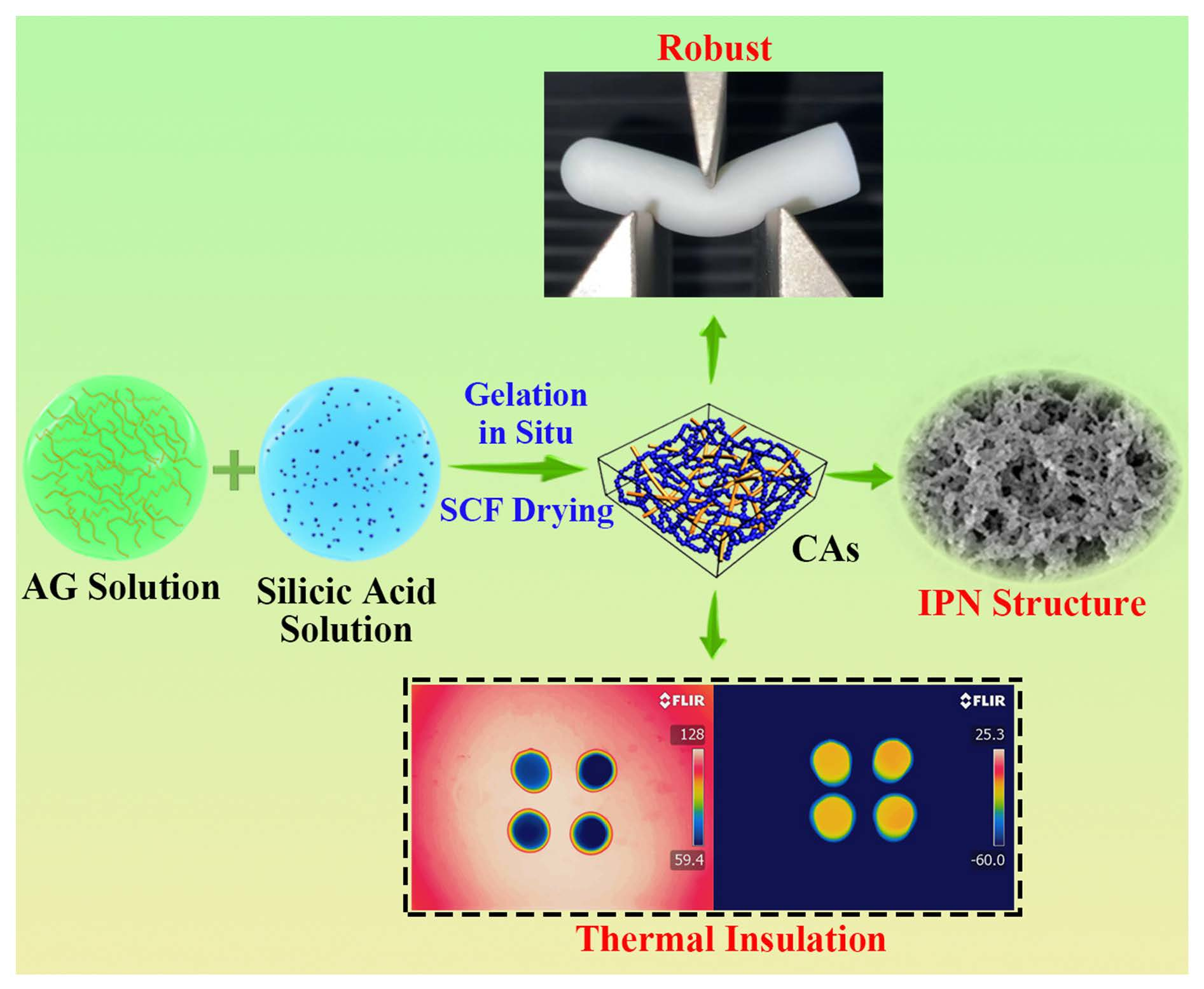
Robust Silica–Agarose Composite Aerogels with Interpenetrating Network Structure by In Situ Sol–Gel Process

1
School of Chemistry and Chemical Engineering, Inner Mongolia University of Science & Technology, Baotou 014010, China
2
Inner Mongolia Key Laboratory of Coal Chemical Engineering & Comprehensive Utilization, Inner Mongolia University of Science & Technology, Baotou 014010, China
3
Aerogel Functional Nanomaterials Laboratory, Inner Mongolia University of Science & Technology, Baotou 014010, China
*
Authors to whom correspondence should be addressed.
Gels 2022, 8(5), 303; https://doi.org/10.3390/gels8050303
Submission received: 28 March 2022 / Revised: 10 May 2022 / Accepted: 10 May 2022 / Published: 16 May 2022

Abstract

:
Aerogels are three-dimensional nanoporous materials with outstanding properties, especially great thermal insulation. Nevertheless, their extremely high brittleness restricts their practical application. Recently, although the mechanical properties of silica aerogels have been improved by regulating the precursor or introducing a polymer reinforcer, these preparation processes are usually tedious and time-consuming. The purpose of this study was to simplify the preparation process of these composite aerogels. A silicic acid solution treated with cation exchange resin was mixed with agarose (AG) to gel in situ, and then composite aerogels (CAs) with an interpenetrating network (IPN) structure were obtained by aging and supercritical CO2 fluid (SCF) drying. Compared to previous works, the presented CAs preparation process is briefer and more environmentally friendly. Moreover, the CAs exhibit a high specific surface area (420.5 m2/g), low thermal conductivity (28.9 mW m−1 K−1), excellent thermal insulation properties, and thermal stability. These results show that these CAs can be better used in thermal insulation.

Graphical Abstract

1. Introduction

Aerogel is an ultraporous three-dimensional nanomaterial obtained by a special drying method of wet gel so that the liquid phase between the gel skeleton is replaced by the gas phase, and the gel skeleton remains intact [1]. Moreover, aerogels have a low density (~0.003–0.5 g/cm3), a high specific surface area (500–1200 m2/g), high porosity (80%~99.8%), and low thermal conductivity (~15 mW m−1 K−1), which have good application prospects in many fields such as separation, thermal insulation, energy storage, batteries, and aerospace [2]. However, traditional inorganic oxide (e.g., silica (SiO2), alumina (Al2O3), and zirconia (ZrO2)) aerogels have inherently high brittleness due to their pearl-necklace-like network, which limits their widespread applications [3,4]. Therefore, researchers constantly exploit a more appropriate approach to prepare silica aerogel materials with excellent mechanical properties, which is critical to meet the demand of their future practical applications [5,6,7].
To date, researchers around the world have mainly utilized precursor regulation [8] and external doping [9] to enhance the mechanical capacity of silica aerogel materials. Initially, the number of nanoparticles and their connection points in the aerogel skeleton were increased by promoting the amount of precursor, and then the strength of the aerogel was improved in a limited range [8]. Following this, Rao et al. [10] prepared flexible aerogels by supercritical drying after gelation of trialkoxysilane reagent RSiX3 (R is alkyl, aromatic or vinyl; X is an alkoxy group) [11,12,13]. The inert group R on the precursor inhibits the formation of rigid Si–O–Si bonds in the gel skeleton and decreases their number, so that the gel skeleton can adapt to certain deformations and show good flexibility. Moreover, researchers have used alkoxy silicon with an alkyl chain as a precursor to gel alone or with other alkoxysilane precursors to endow aerogels more flexibility [14]. Similarly, Gao et al. [15] and Guoqing Zu’s team [16,17,18] used similar flexible chain as precursors to prepare SiO2 aerogels materials, which greatly reduced the brittleness of the gel skeleton and allowed to obtain aerogel materials with a uniform microstructure and super flexibility. However, these expensive precursors increase the production cost of aerogels. To reduce the costs of preparation, researchers had synthesized silica composite aerogels using cheap precursors. Waterglass (sodium silicate) may be a viable and inexpensive alternative to alkoxide precursors. Therefore, sodium silicate produced from biomass ash, such as corn stalk ash [19], rice hull ash [20], groundnut hull ash [21], and fly ash [22], is potential candidate due to its low cost and facile production.
There are also some researchers who have enhanced the mechanical properties of silica aerogels by implementing various reinforcers to toughen their structure [23,24]. In early studies, the easiest way of improving the strength of silica aerogel was to use the fiber reinforcement process. Various reinforced fibrous materials in dispersed or felt materials made of fibers, such as ceramic fiber [25], polymer fiber [26], carbon fiber [27,28], glass cotton mat [29], and polyethylene terephthalate (PET) nonwoven mat [30], have been used as structural reinforcements [31]. However, these composite aerogels may have an uneven distribution of reinforcing fibers during the gelation process, or the relatively macroscopic structural reinforcements in size are incompatible with the nanoscale gel skeleton of silica. Recently, improving the mechanical properties of silica aerogels by polymer coating on the silica gel skeleton or depositing silica nanoparticles on the fibrous polymer matrix has attracted more attention [32]. On the one hand, the silica sols were prepared by the sol–gel method to prepare the silica wet gel, and immersed in the polymer monomer (e.g., methyl methacrylate [33], styrene [34], isocyanate [35], and epoxy [36]), which induced polymerization on the surface of the silica gel skeleton to form an isomorphic coating structure (composite aerogel I obtained from route A in Figure 1). The isomorphic covering method can effectively strengthen the aerogel skeleton, especially the joining of secondary nanoparticles. However, this has also brought about some shortcomings or new problems; for instance, the high cost of preparation and the formation of polymers on the surface of the gel skeleton will fill the voids between primary nanoparticles. This phenomenon shows that the specific surface area of aerogels is significantly reduced, which also limits their application in some fields. On the other hand, the polymer solution has been gelled to obtain polymer wet gels, and the polymer wet gels have been impregnated with silica sols to make the silica sol gelation form an interpenetrating network (IPN) structure (composite aerogel II route B in Figure 1) [37,38,39]. Although the mechanical properties of silica have been improved by constructing flexible polymer substrates via the above two methods, the diffusion of polymer monomers into the silica gel skeleton or the diffusion of silica sols into the polymer matrix are both time-consuming [40] and their preparation conditions are harsh (e.g., gelation at a low temperature to inhibit the gelation of sols before they diffuse into the polymer matrix [41]).
This study aimed to directly mix a polymer solution (i.e., AG solution) with a silicic acid solution in situ to construct composite aerogels II with an IPN structure, as shown in route C in Figure 1 and Figure S1. In the preparation process of CAs, AG first gelled to construct a nanofiber network, and then a SiO2 gel skeleton was formed in the AG nanofibers network in situ to form an IPN structure. Compared to other works [40,42], the construction of a composite aerogel gel skeleton did not require diffusion of one monomer into another, which extremely simplified the preparation process. Moreover, the CAs benefited from the fact that the gelation process of the natural polymer AG without any chemical cross-linking agents and AG nanofibers in the IPN structure of the CAs were more loosely distributed. Then, the CAs were prepared using inorganic Na2O·3SiO2 instead of organic TEOS as the silica source and compounded with AG in situ. This preparation process not only cut down the cost but also made the compound process more environmentally friendly. More importantly, the presented CAs displayed excellent mechanical properties, thermal insulation, and thermal stability, thus promoting the application of aerogels in thermal insulation.

2. Results and Discussion

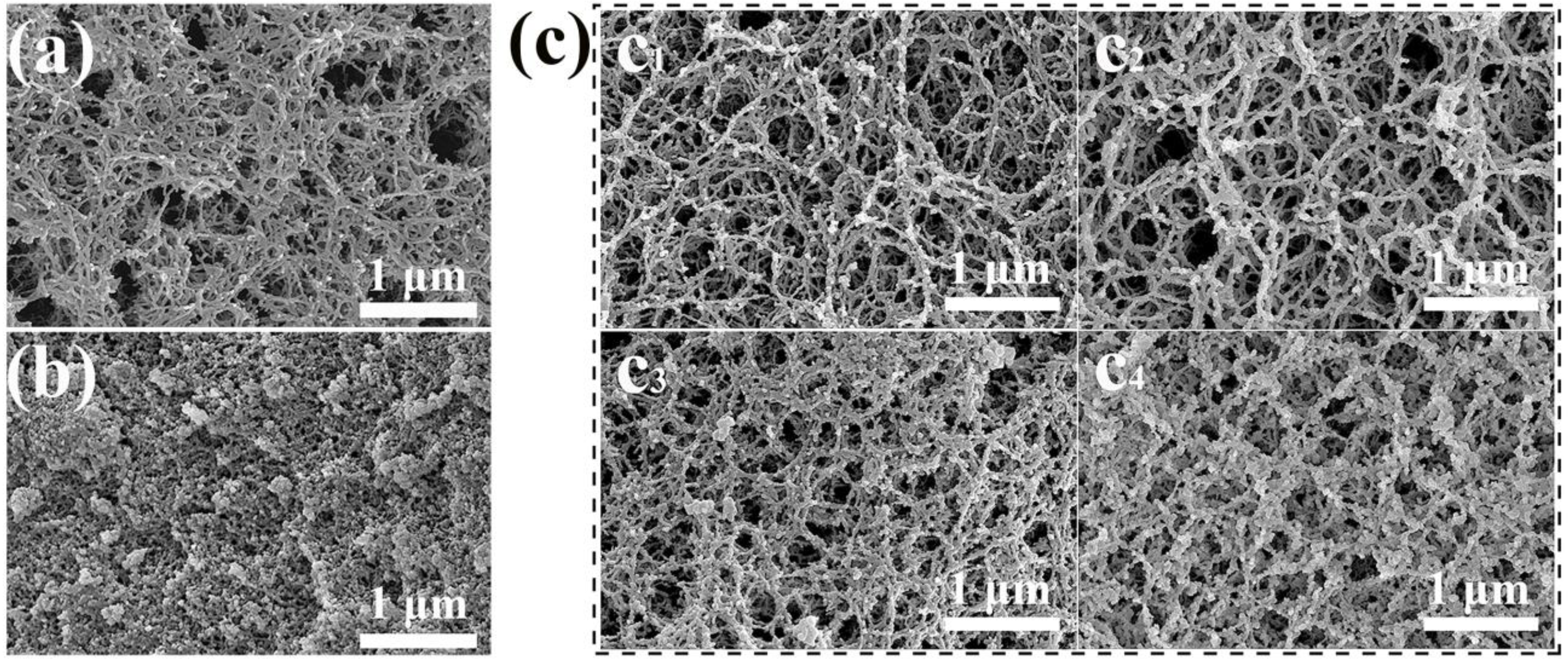
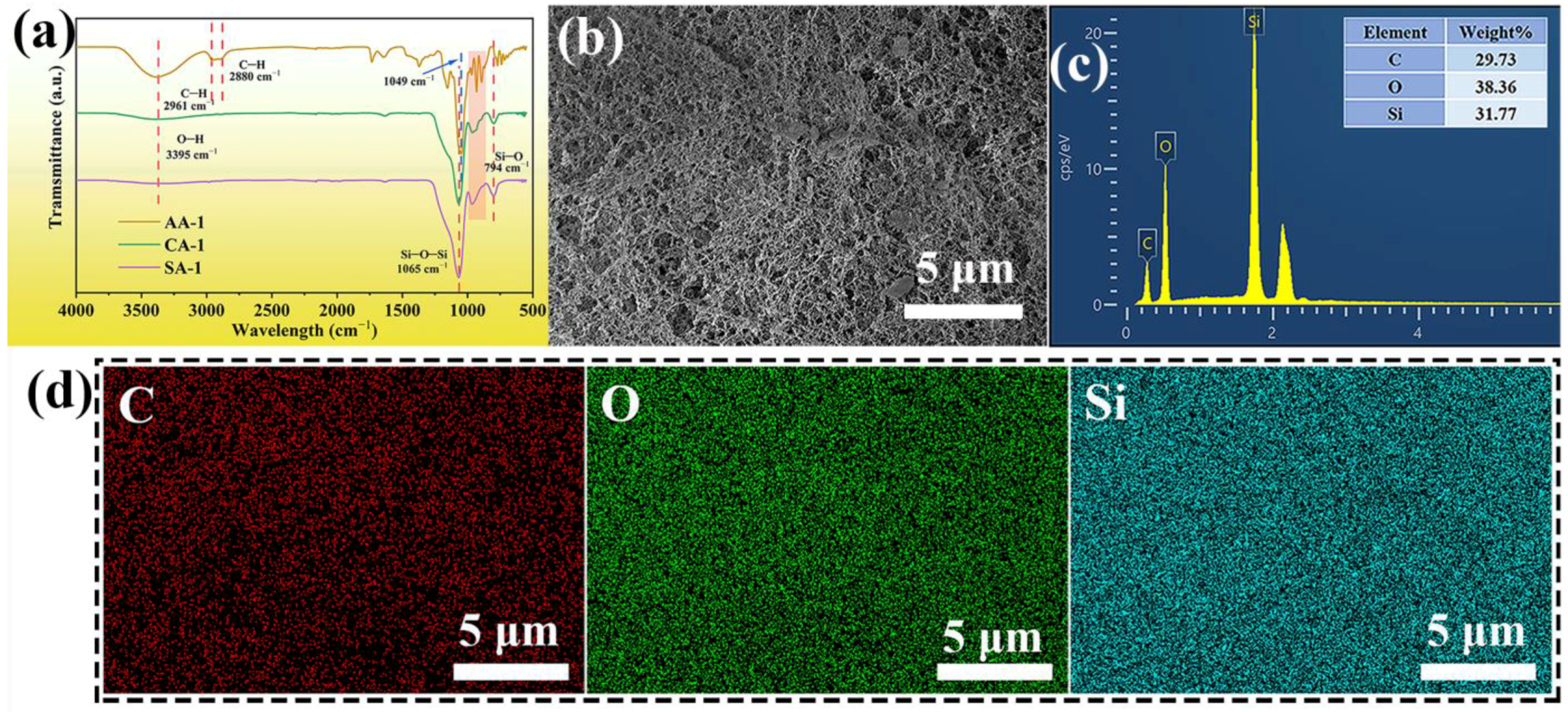
2.1. Microstructures Characterization

The microstructures of agarose aerogel (AA-2), silica aerogel (SA-4), and CAs were revealed by scanning electron microscopy (SEM) images (Figure 2). The 3D network structure of AA-2 consists of disordered and dispersed nanoscale AG nanofibers (Figure 2a). The branching points were firmly fixed, and a 3D network structure was formed by hydrogen bonding or electrostatic attraction between the helical AG molecules and the flexible chains [43,44]. An SEM image of the SA-4 is given in Figure 2b. It can be seen that micrometer-sized SiO2 agglomerations with a typical aerogel structure were produced for pure SAs. However, during the gelation process of the CAs, AG first formed a gel skeleton due to the low-temperature self-coagulation of AG, and SiO2 gelled in the gel skeleton of AG to form an IPN network structure. SEM images of the CAs showed that the IPN structure was formed by a flexible AG and a rigid SiO2 gel skeleton (Figure 2c). CA-1 was mainly composed of AG nanofiber aggregates when the content of SiO2 in the composite solution was low, with a handful of SiO2 nanoparticles attached to the gel skeleton of AG by hydrogen bonding (Figure 2c1). For larger contents of SiO2, as in CA-2 and CA-3, a SiO2 gel skeleton was gradually formed in the AG nanofiber network (Figure 2c2,c3). This phenomenon indicates that a nanoscale IPN structure was constructed. When the content of SiO2 in the CAs was improved further, the SiO2 gel skeleton became denser, as shown in CA-4 (Figure 2c4). Compared to other composite aerogels enhanced with short fibers in a dispersed [26] or cellulose nanofiber network [45], the AG nanofibers were more evenly distributed in the CA network. Moreover, the IPN structure of the CAs made full use of these strong link points to prevent them separating from each other to maintain the macroscopic integrity of the sample.
Attenuated total reflection Fourier transform infrared (ATR-FTIR) spectra of the samples are presented in Figure 3a. In the ATR-FTIR spectrum of AAs, the characteristic peaks at 3395 cm−1 and 1049 cm−1 indicate the O–H stretching vibration and glycoside stretching bond, respectively [44,46]. The peaks appeared at 2961 and 2880 cm−1 could be corresponded to symmetric and the asymmetric vibrations of C–H groups, respectively [47]. There were emerging peaks for CAs at around 1065, 961, and 794 cm−1, attributed to Si–O–Si stretching vibration, Si–OH bending vibration, and Si–O stretching vibration [48], which was not found in the ATR-FTIR spectra of the AAs. Similarly, these characteristic peaks also appeared in the SAs. This phenomenon shows that the CAs had Si–O–Si bonds that formed a gel skeleton of silica, and Si–O bonds were formed by the reaction between SiO2 and the AG surface. Moreover, ATR-FTIR spectrum of CA-1 and SA-1 was almost similar. This phenomenon could be because of SiO2 nanoparticles were tightly attached to the surface of the AG nanofibers during the formation of the SiO2 gel skeleton, which made the weak absorption peak of AAs difficult to observe in the ATR-FTIR spectrum of the CAs. Moreover, strong peak at 1049 cm−1 (glycoside stretching bond) for AA-1 and characteristic peak at 1065 cm−1 (Si–O–Si) for CA-1 were almost overlapping in the ATR-FTIR spectra. Thus, it is impossible to distinguish in the CAs. However, in the 930~960 cm−1 (in the red box of Figure 3), the CAs have the common characteristic peak of both AAs and SAs, which indicates that the CAs are composite of AG and SiO2. Therefore, the peak of O–H at 3395 cm−1 of the CAs was weaker than that of the AAs. This further indicates that silica was successfully formed in the AG skeleton and combined with AG in CAs. In conclusion, ATR-FTIR spectra analysis proved that CAs had successfully been prepared.
According to the microstructure of CA-2 (Figure 3b), energy-dispersive X-ray spectra (EDS) were captured to investigate the weight concentration and element distribution of CA-2 (Figure 3c,d). AA-1 showed carbon and oxygen peaks without silicon peaks (Figure S2), while SA-1 displayed silicon and oxygen peaks (Figure S3). However, there were not only carbon and oxygen peaks but also silicon peaks in the EDS of CA-2 (Figure 3c). These appearances further indicate that successful combination of SiO2 and AG. From the EDS mapping images (Figure 3d), it can be seen that the distribution of Si in CA-2 was relatively even, which also illustrates that the gel skeleton of silica was relatively uniformly distributed in the CAs.

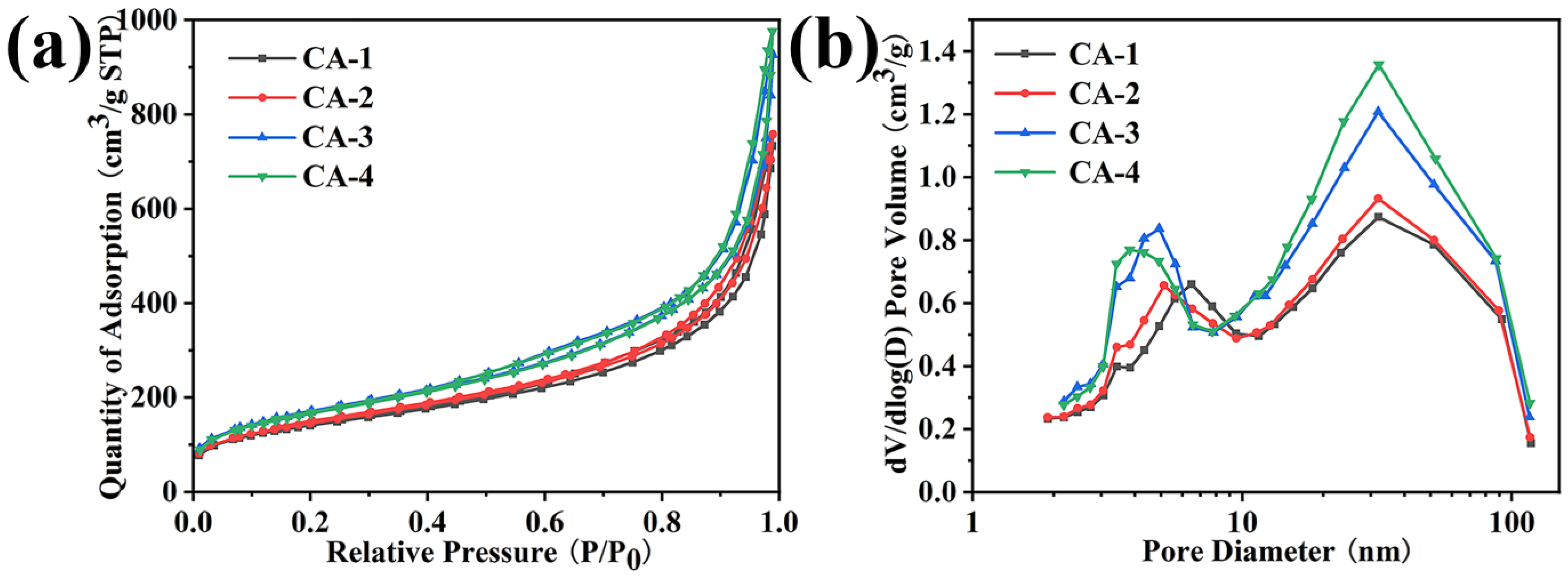
2.2. Nitrogen Adsorption–Desorption Test

The N2 adsorption–desorption curves, Barrett–Joyner–Halenda (BJH) pore size distributions, specific surface areas, and average pore sizes of the CAs, AAs, and SAs are shown in Figure 4 and Figure S4 and Table 1. In the N2 adsorption–desorption isotherm, the CAs, AAs, and SAs showed a type IV isotherm of the hysteresis loop [49,50], indicating the formation of mesoporous structure (Figure 4a and Figure S4a,c). The hysteresis loops of the CAs became more obvious as the SiO2 concentration increased. With the decrease in the concentration of AG, the N2 adsorption of the AAs decreased, while the SAs increased with the increase in the SiO2 content. This phenomenon also proves that the N2 adsorption of the CAs gradually increased with the increase in the SiO2 content. Remarkably, the most probable distribution of the pore size of the CAs was mainly around 30 nm, and the diameter of a small amount of the pores was between 3 and 7 nm in the BJH pore size distributions (Figure 4b), which also occurred in the SAs (Figure S4d). Although the BJH pore size distributions showed that the CAs had a mesoporous structure to a certain extent, the total mesoscale pore volume of the CAs was relatively higher than that of the AAs (Table 1 and Figure S4b) and lower than that of the SAs (Figure S4d). The pore volume of the CAs was slight increase with the increase in SiO2 content (Table 1). These results could be due to some of the SiO2 nanoparticles tightly adhering to the AG nanofibers to restrain the formation of a mesoporous structure, which was in agreement with the SEM analysis. Moreover, with the increase in SiO2 concentration, the density of the CAs increased to a certain extent and the porosity slightly decreased owing to the formation of SiO2 gel skeleton. The specific surface areas of the CAs gradually increased from 272.4 to 420.5 m2/g with an increase in the SiO2 content according to the results of a BET test (Table 1). Compared to the other silica-based aerogels, the CAs showed lower density and larger specific surface area (Table 2). On the one hand, when the concentration of SiO2 was low, the specific surface area of the CAs was a little higher than that of the natural AAs due to many SiO2 aggregates without interconnection and was attached in the AG nanofibers network to increase the AG surface roughness (Table 1). On the other hand, a greater and rougher SiO2 gel skeleton formed in the AG nanofiber network as the concentration of SiO2 increased further, which made the specific surface areas of the CAs gradually increased. The average desorption pore size (10.5–11.8 nm) of the CAs is presented in Table 1, showing almost the same trend as the specific surface area, while the average desorption pore size showed a smaller range of variation than the specific surface area because of it only reflecting the pore size of the mesoporous range according to the BET analysis. Therefore, the content of SiO2 has an important impact on the gel skeleton of AG–SiO2 composite aerogels.

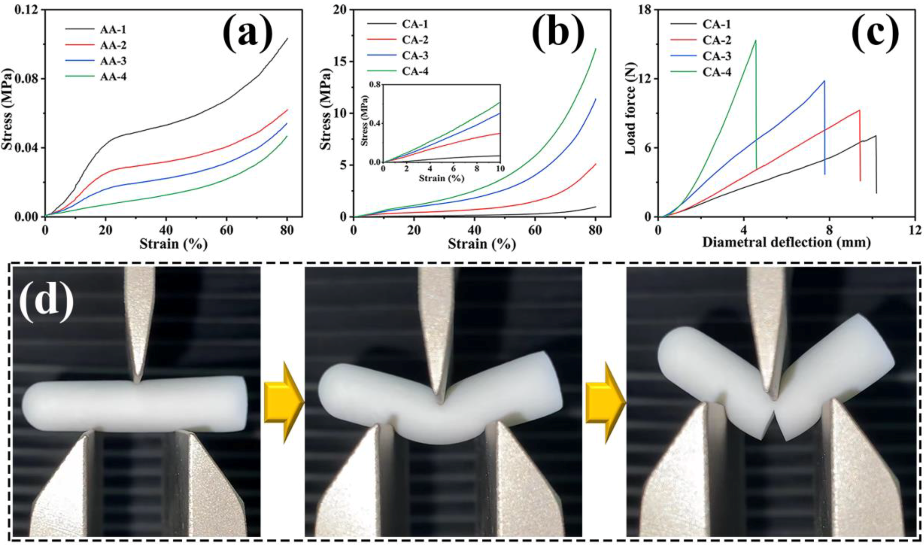
2.3. Mechanical Properties

Sufficient mechanical strength plays a significant role in the application of thermal insulation materials. The mechanical properties of the prepared CAs were studied by a compressive test and a three-point bending test. Amusingly, brittle SAs combined with extremely soft AAs could produce CAs with an amazing pliability and compressive property. The mechanical properties of the AAs prepared with different concentrations of AG are presented in Figure 5a. The AAs could withstand compressive stress over 80%. When the strain was less than 20%, the compressive stress of the AAs with a low concentration increased at a slow rate, while those AAs with a higher concentration increased more rapidly. This explains that the gel skeleton of the AAs with a higher concentration gradually became more compact, which was equivalent to reducing the space of deformation. It is worth noting that the AAs did not have an obviously brittle point at higher stress. This was mainly because the gel skeleton of the AAs, with flexibility itself, can easily be deformed without breaking when it was impacted by external force. In significant contrast to the brittleness of traditional SAs, the CAs were compressed to more than 80% strains without cracks, demonstrating remarkable flexibility and nonbrittleness (Figure 5b). All of the stress–strain curves of the CAs displayed three stages, including a linear elastic district at low strain values (below 10%), a plastic district with a relatively gently growth curve at middling strain values (from 10% to 60% strain), and the final densification stage with a rapidly rose stress at high strain values (over 60% strain) [56,57]. The compression modulus of the CAs gradually increased at a low SiO2 content, and then dramatically increased to 6.23 MPa for CA-4 (Table 1). It is worth mentioning that the compression modulus of the CAs is higher than that of some silica-based aerogels, such as silica/polyimide (SiO2/PI) nanocomposite aerogel (1.9 MPa), silica nanotube aerogels (0.3~1.9 MPa), and hydrophobic silica-based aerogel (0.2 MPa) (Table 2). This further confirmed the excellent mechanical properties of the CAs prepared by compounding AG and silica. In particular, the dramatic increase in compressive stress with a high concentration was caused by the formation of more rigid gel skeletons of SiO2 in the AG nanofibers network to resist the impact of external forces more effectively. Therefore, by using this synthesized in situ method, CAs with the IPN structure can be obtained by relying on the SiO2 concentration. Furthermore, the CAs were able to withstand a large diametral deformation (i.e., approximately 4–10 mm) without breaking and the breaking force was in the range of around 6–10 N, as proved in the three-point bending tests with a fixture span of 15 mm (Figure 5c). During this process, a crack of CA-1 appeared just after 10 mm diametral deformation as shown in Figure 5d. This indicates that the CAs had good flexibility. When the concentration of SiO2 gradually increased, the diametral deformation gradually decreased. This may be because the free movement of the AG nanofiber was restricted when more and denser rigid gel skeletons were formed in AG nanofibers network, which resulted in the compression of the free deformation space of AG nanofiber network [41].

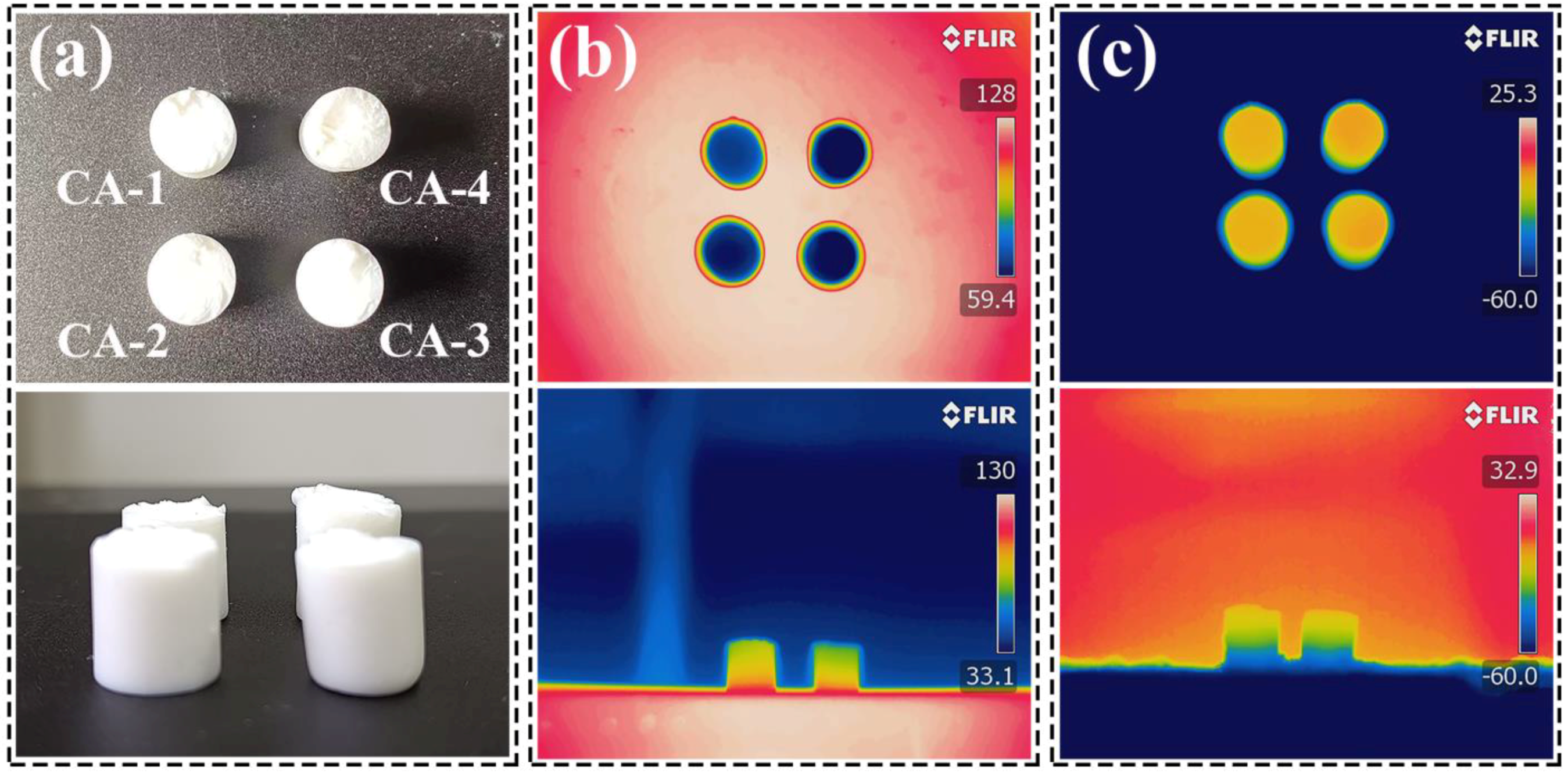
2.4. Thermal Insulation Performance

The CAs displayed low thermal conductivity, which was almost similar to native SAs [58] (Table 1). It is slightly superior to those of traditional insulating materials such as polymer foam (20~50 mW m−1 K−1) and mineral wool (35~80 mW m−1 K−1) [18] and is competitive to those of the similar silica-based aerogels [9,23,55,56,57,58] at a room temperature (Table 2). For the four kinds of CAs with different SiO2 content explored in this work, the thermal conductivity of those CAs increased to some extent with the increased of SiO2 content. This could be understood as the gel skeleton of the CAs being mainly composed of a large number of AG nanofibers with a loose microstructure, so that CA-1 showed relatively lower thermal conductivity. When the concentration of SiO2 further increased (CA-3 and CA-4), more and denser gel skeletons of SiO2 were formed in the AG nanofibers, leading to a density increase and a decrease in porosity. This could increase the heat transfer caused by contact between the solids, resulting in slightly increasing the thermal conductivity. However, the thermal conductivity of the CAs was still low because of their mesoporous structure. Therefore, the concentration of SiO2 is critical to prepare CAs in terms of their thermal insulation properties.
To further prove the thermal insulating performances, the surface temperature difference of the CAs during the heating and cooling processes was recorded using an infrared thermal camera as shown in Figure 6 and Figure S5. Optical photos of the CAs of the main and side views are shown in Figure 6a and Figure S5a. The temperature difference change of the CAs at different heat source temperatures (60, 90, 110, and 130 °C) in the same view is shown in Figure 6b and Figure S5b, which show that the temperature difference gradually increased as the hot plate gradually increased, and the temperature difference could reach 68 °C when the temperature was close to 130 °C. Although the thermal conductivity of CA-1 was relatively low at room temperature, the infrared photo of CA-1 did not show a good thermal insulation effect compared to the other CAs at a high temperature. This may be because the high porosity of CA-1, but the lack of mesoporous content that can more effectively inhibit the diffusion of air molecules, resulting in poor thermal insulation after heating. With the increase in the solid concentration, the gradual formation of more SiO2 gel frameworks in the AG nanofiber network could inhibit the heat transfer more effectively. In the meantime, the temperature difference of the CAs was approximately 40–50 °C at a low temperature (–60 °C) as shown in Figure 6c and Figure S5c. This illustrates that the CAs had excellent thermal insulation properties, whether in a high- or low-temperature environment.

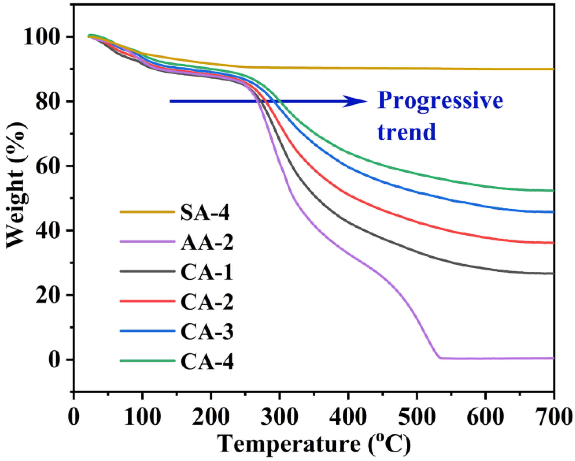
2.5. Thermal Stability

Outstanding thermal stability of materials is crucial for their thermal insulation application, so the thermal stability of the materials was determined by thermogravimetric analysis (TGA), as shown in Figure 7. First, SA-4, AA-2, and the CAs lost approximately 10% of their weight at 30–250 °C. This may be because of the adsorption of water molecules on the sample gel skeleton surface [7,58]. However, the weight loss of SA-4 at 250–700 °C was eventually maintained at 10%. Moreover, the temperature of decomposition of AG in the CAs gradually shifted from approximately 250 °C to approximately 260 °C (Figure 7) as the SiO2 concentration increased. When the weight gradually decreased to 80% of the initial weight, as shown by the dark blue arrow in Figure 7, the temperature corresponding to the CAs gradually increased from 260 °C to approximately 300 °C as the SiO2 content increased. Therefore, SiO2 was able to restrain decomposition of the AG gel skeleton, which improved the thermal stability of the CAs. Furthermore, AA-2 completely degraded at approximately 510 °C and lost almost 100% of its weight. Nevertheless, the CAs completely degraded at approximately 650 °C and lost approximately 25%–50% of their weight. This illustrates that more and denser SiO2 gel skeletons formed in the AG nanofibers network as the concentration of SiO2 increased, which is beneficial for improving the thermal stability of CAs.

3. Conclusions

In this work, robust composite aerogels were prepared by an AG solution mixed with a silicate solution in situ to gradually form an IPN structure. In the gelation process of the CAs, the flexible AG firstly gelled to construct a nanofiber network due to AG’s self-gelling feature, and then a rigid SiO2 gel skeleton was formed in the loose AG nanofibers network to form an IPN structure. Compared to other polymer toughening technologies that can effectively improve aerogels, the time-consuming diffusion of a reaction substance into other wet gels was not involved here, which made the preparation process simpler and more efficient. Furthermore, cheaper water glass (Na2O·3SiO2) was used to instead of traditional TEOS as a silicon source, which greatly reduced the costs and was environmentally friendly. In addition, the CAs displayed a low density (0.079 g/cm3), high porosity (96.0%), high specific surface area (as high as 420.5 m2/g), and excellent mechanical properties. Especially, the CAs also exhibited good thermal insulation properties and thermal stability, which is important for its application in the field of thermal insulation. This work offers a novel and facile design of composite aerogels, which also provides new ideas for the preparation of high-performance composite aerogels.

4. Materials and Methods

4.1. Materials

First, 732 cation exchange resin and sodium silicate (Na2O·3SiO2) were purchased from Macklin Biochemical Co., Ltd. (Shanghai, China). Agarose (AG) was bought from Beijing Wobisen Technology Co., Ltd. (Beijing, China). Sulfuric acid (H2SO4), sodium hydroxide (NaOH), ammonium hydroxide (NH3·H2O) and ethanol were obtained from Beijing Chemical Reagent Co., Ltd. (Beijing, China). All chemicals were of analytical grade and were used as received without further purification.

4.2. Preprocessing of 732 Cation Exchange Resin

First, the strong acid styrene 732 cation exchange resins was washed with hot water at 70–80 °C to remove impurities and make the effluent colorless. Next, the cation exchange resin in the exchange column was soaked in 1 mol/L of H2SO4 (2 times the amount of resin) for 2 h, rinsed with 1 mol/L of H2SO4 (4 times the amount of resin), and washed to neutral with deionized water.

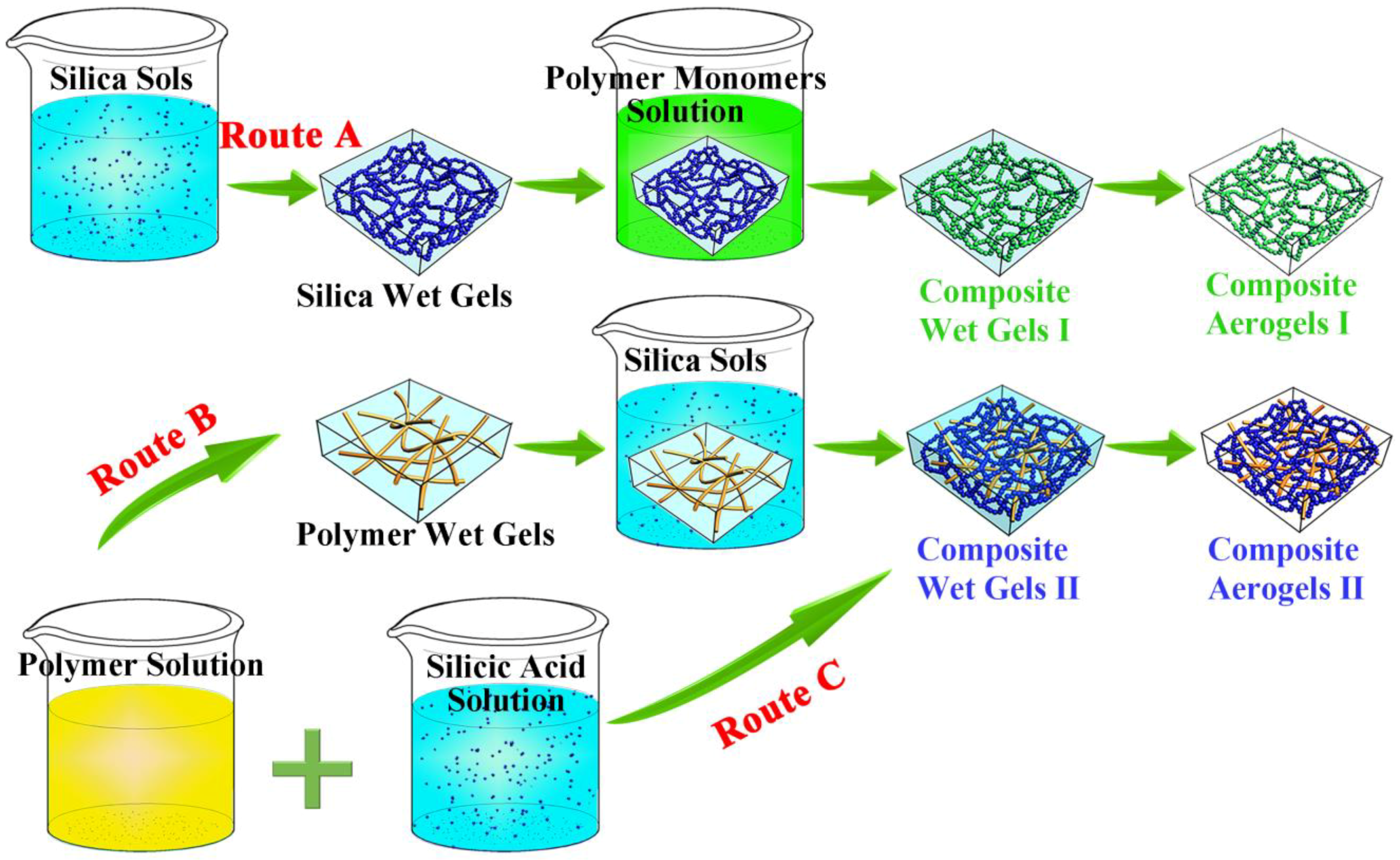
4.3. Preparation of AG–SiO2 Composite Aerogels

First, the sodium silicate solutions were poured into the excess cation exchange resin to remove Na+ in the exchange column to obtain silicic acid solutions (pH = 2~3). The silicic acid solution (SiO2 in solution, 10% w/w) and AG solution (3% w/w) were stirred to mix at 80 °C with different volume ratios of AG to silicic acid solution (1:1, 1:2, 1:3, and 1:4), and their pH was adjusted to 5~6 by 0.1 mol/L of NH3·H2O (less than 0.2 μL). Then, the mixed sols were poured into Petri dishes (90 mm) or centrifuge tubes (5 mL) to form AG–SiO2 composite gels. Those composite gels in the Petri dishes with a diameter of 90 mm were cut into 15 mm × 15 mm × 20 mm cubes by blade. The composite gels were aged in a mixture of ethanol and water at 50 °C for 1.5 h to harden the silica gel skeleton and completely replace the liquid in the composite wet gels with ethanol. The composite wet gels were dried by supercritical CO2 fluid at a flow rate of 5–15 L/h at 11 MPa and 40 °C for 2.5 h to obtain AG–SiO2 composite aerogels, labeled as CA-1, CA-2, CA-3, and CA-4 according to volume ratio of AG and silicate mixture solution (1:1, 1:2, 1:3, or 1:4).

4.4. Preparation of AAs

The preparation process of the AAs was similar to that of the CAs, with only the silicic acid solutions being replaced by deionized water. In the first place, different concentrations of the AG solutions were prepared by mixing the AG solution (3% w/w) with deionized water in a microwave at different volume ratios (1:1, 1:2, 1:3, and 1:4). Then, the AG solutions were poured into a Petri dish with a diameter of 90 mm and cooled naturally at room temperature to prepare AG gel. Next, the AG hydrogels were cut into 15 mm × 15 mm × 20 mm cubes by a blade. Finally, the AG hydrogels were replaced by anhydrous ethanol solvents and dried by SCF to obtain AAs, labeled as AA-1, AA-2, AA-3, and AA-4 according to the concentrate of AG (1.5%, 1.0%, 0.75%, or 0.6%), as shown in Figure S6.

4.5. Preparation of SAs

The preparation process of the SAs was similar to that of the CAs, with only the AG solutions being replaced by deionized water. First, different concentrations of silicic the acid solution was prepared by mixing silicic acid solution (10% w/w) with deionized water at different volume ratios (1:1, 1:2, 1:3, and 1:4). Then, the silicic acid solutions were adjusted to pH = 5~6 by 0.1 mol/L of NH3·H2O (less than 0.2 μL) and poured into centrifuge tubes to achieve gelation. Next, the SiO2 gels were aged in a mixture of ethanol and water at 50 °C for 1.5 h to harden the silica gel skeleton. Finally, SAs were obtained by the ethanol solution replacement method and SCF drying, labeled as SA-1, SA-2, SA-3, and SA-4 according to the concentrate of SiO2 (5%, 6.7%, 7.5%, or 8%), as shown in Figure S7.

4.6. Characterization

The micromorphology, functional groups (FTIR), pore size distributions, density, porosity, and the specific surface areas of the CAs were determined. The mechanical properties, thermal insulation properties and thermal stability were also evaluated. The detailed characterization methods are provided in the Supplementary Materials. The abbreviations in the work are shown in Table 3.

Supplementary Materials

The following are available online at https://www.mdpi.com/article/10.3390/gels8050303/s1: Figure S1. Flowchart illustrating the overall processes used in this work; Figure S2. SEM images (a), weight concentration from EDS (b) and EDS elemental mapping images (c) for C and O elements of the AA-1; Figure S3. SEM images (a), weight concentration from EDS (b) and EDS elemental mapping images (c) for O and Si elements of the SA-1; Figure S4. (a) N2 adsorption-desorption isotherms and (b) BJH pore-size distribution of AAs. (c) N2 adsorption-desorption isotherms and (d) BJH pore-size distribution of SAs; Figure S5. (a) Optical photo at main and side views, respectively, of the CAs. FLIR images of the CAs (b) on the heating base plate at different temperatures (60, 90, 110, and 130 °C) and (c) on aluminum plate of dry ice (–60 °C) at main and side views, respectively.; Figure S6. Image of the AAs; Figure S7. Image of the SAs.

Author Contributions

Writing—original draft, investigation, and writing—review and editing, X.Y.; data curation, X.Y. and P.J.; conceptualization, project administration, validation, funding acquisition, and writing—review and editing, R.F. and H.S.; methodology, R.X., Y.L. and C.J.; validation, Q.S.; data curation, C.M.; visualization, H.Y.; supervision, and conceptualization, J.G.; project administration, Y.W. All authors have read and agreed to the published version of the manuscript.

Funding

This research was funded by the Innovation Fund of Inner Mongolia University of Science & Technology (2018QDL-B01), the Natural Science Foundation of Inner Mongolia (2019BS05022, 2019LH02004), the Science and Technology Plan Project of Inner Mongolia Autonomous Region (2020GG0152), the National Natural Science Foundation of China (52164013), and the Scientific Research Projects of Colleges and Universities of Inner Mongolia (NJZZ20087).

Institutional Review Board Statement

Not applicable.

Informed Consent Statement

Not applicable.

Data Availability Statement

The data presented in this study are available on request from the corresponding author.

Acknowledgments

The authors extend their thanks for the financial support from the Human Resources and Social Security Department of Inner Mongolia.

Conflicts of Interest

The authors declare no conflict of interest.

References

  1. Sai, H.; Fu, R.; Xiang, J.; Guan, Y.; Zhang, F. Fabrication of elastic silica-bacterial cellulose composite aerogels with nanoscale interpenetrating network by ultrafast evaporative drying. Compos. Sci. Technol. 2018, 155, 72–80. [Google Scholar] [CrossRef]
  2. Sai, H.; Xing, L.; Xiang, J.; Cui, L.; Jiao, J.; Zhao, C.; Li, Z.; Li, F.; Zhang, T. Flexible aerogels with interpenetrating network structure of bacterial cellulose–silica composite from sodium silicate precursor via freeze drying process. RSC Adv. 2014, 4, 30453–30461. [Google Scholar] [CrossRef]
  3. Sai, H.; Fu, R.; Xing, L.; Xiang, J.; Li, Z.; Li, F.; Zhang, T. Surface modification of bacterial cellulose aerogels’ web-like skeleton for oil/water separation. ACS Appl. Mater. Interfaces 2015, 7, 7373–7381. [Google Scholar] [CrossRef] [PubMed]
  4. Gu, J.; Ji, C.; Fu, R.; Yang, X.; Wan, Z.; Wen, L.; Song, Q.; Liu, Y.; Wang, Y.; Sai, H. Robust SiO2–Al2O3/Agarose Composite Aerogel Beads with Outstanding Thermal Insulation Based on Coal Gangue. Gels 2022, 8, 165. [Google Scholar] [CrossRef] [PubMed]
  5. Sun, H.; Bi, H.; Lin, X.; Cai, L.; Xu, M. Lightweight, Anisotropic, Compressible, and Thermally-Insulating Wood Aerogels with Aligned Cellulose Fibers. Polymers 2020, 12, 165. [Google Scholar] [CrossRef] [PubMed] [Green Version]
  6. Shang, L.; Lyu, Y.; Han, W. Microstructure and Thermal Insulation Property of Silica Composite Aerogel. Materials 2019, 12, 993. [Google Scholar] [CrossRef] [Green Version]
  7. Li, C.; Chen, Z.; Dong, W.; Lin, L.; Zhu, X.; Liu, Q.; Zhang, Y.; Zhai, N.; Zhou, Z.; Wang, Y.; et al. A review of silicon-based aerogel thermal insulation materials: Performance optimization through composition and microstructure. J. Non-Cryst. Solids 2021, 553, 120517–120534. [Google Scholar] [CrossRef]
  8. Karamikamkar, S.; Naguib, H.E.; Park, C.B. Advances in precursor system for silica-based aerogel production toward improved mechanical properties, customized morphology, and multifunctionality: A review. Adv. Colloid Interface Sci. 2020, 276, 102101–102129. [Google Scholar] [CrossRef]
  9. Zhang, R.; An, Z.; Zhao, Y.; Zhang, L.; Zhou, P. Nanofibers reinforced silica aerogel composites having flexibility and ultra-low thermal conductivity. Int. J. Appl. Ceram. Technol. 2020, 17, 1531–1539. [Google Scholar] [CrossRef]
  10. Nadargi, D.Y.; Latthe, S.S.; Hirashima, H.; Rao, A.V. Studies on rheological properties of methyltriethoxysilane (MTES) based flexible superhydrophobic silica aerogels. Microporous Mesoporous Mater. 2009, 117, 617–626. [Google Scholar] [CrossRef]
  11. Cai, L.; Shan, G.R. Elastic silica aerogel using methyltrimethoxysilane precusor via ambient pressure drying. J. Porous Mater. 2015, 22, 1455–1463. [Google Scholar] [CrossRef]
  12. Zhong, L.; Chen, X.H.; Song, H.H.; Guo, K.; Hu, Z.J. Highly flexible silica aerogels derived from methyltriethoxysilane and polydimethylsiloxane. New J. Chem. 2015, 39, 7832–7838. [Google Scholar] [CrossRef]
  13. Wang, L.; Feng, J.; Jiang, Y.; Li, L.; Feng, J. Elastic methyltrimethoxysilane based silica aerogels reinforced with polyvinylmethyldimethoxysilane. RSC Adv. 2019, 9, 10948–10957. [Google Scholar] [CrossRef] [PubMed] [Green Version]
  14. Guo, H.Q.; Nguyen, B.N.; McCorkle, L.S.; Shonkwiler, B.; Meador, M.A.B. Elastic low density aerogels derived from bis 3-(triethoxysilyl)propyl disulfide, tetramethylorthosilicate and vinyltrimethoxysilane via a two-step process. J. Mater. Chem. 2009, 19, 9054–9062. [Google Scholar] [CrossRef]
  15. Yun, S.; Luo, H.J.; Gao, Y.F. Low-density, hydrophobic, highly flexible ambientpressure-dried monolithic bridged silsesquioxane aerogels. J. Mater. Chem. A 2015, 3, 3390–3398. [Google Scholar] [CrossRef]
  16. Zu, G.Q.; Kanamori, K.; Maeno, A.; Kaji, H.; Nakanishi, K. Superflexible Multifunctional Polyvinylpolydimethylsiloxane-Based Aerogels as Efficient Absorbents, Thermal Superinsulators, and Strain Sensors. Angew. Chem. Int. Ed. 2018, 57, 9722–9727. [Google Scholar] [CrossRef] [Green Version]
  17. Zu, G.Q.; Shimizu, T.; Kanamori, K.; Zhu, Y.; Maeno, A.; Kaji, H.; Shen, J.; Nakanishi, K. Transparent, Superflexible Doubly Cross-Linked Polyvinylpolymethylsiloxane Aerogel Superinsulators via Ambient Pressure Drying. Acs Nano 2018, 12, 521–532. [Google Scholar] [CrossRef]
  18. Zu, G.Q.; Kanamori, K.; Shimizu, T.; Zhu, Y.; Maeno, A.; Kaji, H.; Nakanishi, K.; Shen, J. Versatile Double-Cross-Linking Approach to Transparent, Machinable, Supercompressible, Highly Bendable Aerogel Thermal Superinsulators. Chem. Mater. 2018, 30, 2759–2770. [Google Scholar] [CrossRef] [Green Version]
  19. Kamaraj, M.; Kamble, S.; Sonia, S. Facile Synthesis of Silica Composites with Oil Sorption Efficiency from a Vital Agricultural Waste of Corn Stalk Cultivated in Bishoftu, Ethiopia. Adsorpt. Sci. Technol. 2021, 2021, 7205135. [Google Scholar] [CrossRef]
  20. Steven, S.; Restiawaty, E.; Pasymi, P.; Bindar, Y. An appropriate acid leaching sequence in rice husk ash extraction to enhance the produced green silica quality for sustainable industrial silica gel purpose. J. Taiwan Inst. Chem. E 2021, 122, 51–57. [Google Scholar] [CrossRef]
  21. Kaya, G.G.; Deveci, H. Modified silica xerogel derived from groundnut hull ash by alkyl-ammonium salt for epoxy nanocomposites: Synergistic effects on thermal stability and flame retardancy. Thermochim. Acta 2020, 689, 178637–178647. [Google Scholar] [CrossRef]
  22. Shen, M.; Jiang, X.; Zhang, M.; Guo, M. Synthesis of SiO2–Al2O3 composite aerogel from fly ash: A low-cost and facile approach. J. Sol-Gel Sci. Technol. 2020, 93, 281–290. [Google Scholar] [CrossRef]
  23. Du, A.; Wang, H.Q.; Zhou, B.; Zhang, C.; Wu, X.L.; Ge, Y.T.; Niu, T.T.; Ji, X.J.; Zhang, T.; Zhang, Z.H.; et al. Multifunctional Silica Nanotube Aerogels Inspired by Polar Bear Hair for Light Management and Thermal Insulation. Chem. Mater. 2018, 30, 6849–6857. [Google Scholar] [CrossRef]
  24. Song, Q.; Miao, C.; Sai, H.; Gu, J.; Wang, M.; Jiang, P.; Wang, Y.; Fu, R.; Wang, Y. Silica-Bacterial Cellulose Composite Aerogel Fibers with Excellent Mechanical Properties from Sodium Silicate Precursor. Gels 2021, 8, 17. [Google Scholar] [CrossRef] [PubMed]
  25. An, L.; Wang, J.; Petit, D.; Armstrong, J.N.; Hanson, K.; Hamilton, J.; Souza, M.; Zhao, D.; Li, C.; Liu, Y. An all-ceramic, anisotropic, and flexible aerogel insulation material. Nano Lett. 2020, 20, 3828–3835. [Google Scholar] [CrossRef] [PubMed]
  26. Markevicius, G.; Ladj, R.; Niemeyer, P.; Budtova, T.; Rigacci, A. Ambient-dried thermal superinsulating monolithic Silica-based aerogels with short cellulosic fibers. J. Mater. Sci. 2016, 52, 2210–2221. [Google Scholar] [CrossRef]
  27. Slosarczyk, A. Carbon Fiber-Silica Aerogel Composite with Enhanced Structural and Mechanical Properties Based on Water Glass and Ambient Pressure Drying. Nanomaterials 2021, 11, 258. [Google Scholar] [CrossRef]
  28. Hung, W.-C.; Horng, R.S.; Shia, R.-E. Investigation of thermal insulation performance of glass/carbon fiber-reinforced silica aerogel composites. J. Sol-Gel Sci. Technol. 2021, 97, 414–421. [Google Scholar] [CrossRef]
  29. Mazrouei-Sebdani, Z.; Begum, H.; Schoenwald, S.; Horoshenkov, K.V.; Malfait, W.J. A review on silica aerogel-based materials for acoustic applications. J. Non-Cryst. Solids 2021, 562, 120770–120786. [Google Scholar] [CrossRef]
  30. Rasyid, M.A.; Salim, M.; Akil, H.; Karger-Kocsis, J.; Ishak, Z.M. Non-woven flax fibre reinforced acrylic based polyester composites: The effect of sodium silicate on mechanical, flammability and acoustic properties. Express Polym. Lett. 2019, 13, 553–564. [Google Scholar] [CrossRef]
  31. Lin, J.; Li, G.; Liu, W.; Qiu, R.; Wei, H.; Zong, K.; Cai, X. A review of recent progress on the silica aerogel monoliths: Synthesis, reinforcement, and applications. J. Mater. Sci. 2021, 56, 10812–10833. [Google Scholar] [CrossRef]
  32. Randall, J.P.; Meador, M.A.B.; Jana, S.C. Tailoring Mechanical Properties of Aerogels for Aerospace Applications. ACS Appl. Mater. Interfaces 2011, 3, 613–626. [Google Scholar] [CrossRef] [PubMed]
  33. Boday, D.J.; Keng, P.Y.; Muriithi, B.; Pyun, J.; Loy, D.A. Mechanically reinforced silica aerogel nanocomposites via surface initiated atom transfer radical polymerizations. J. Mater. Chem. 2010, 20, 6863–6865. [Google Scholar] [CrossRef]
  34. Nguyen, B.N.; Meador, M.A.; Tousley, M.E.; Shonkwiler, B.; McCorkle, L.; Scheiman, D.A.; Palczer, A. Tailoring elastic properties of silica aerogels cross-linked with polystyrene. ACS Appl. Mater. Interfaces 2009, 1, 621–630. [Google Scholar] [CrossRef] [PubMed]
  35. Zhang, G.; Dass, A.; Rawashdeh, A.-M.M.; Thomas, J.; Counsil, J.A.; Sotiriou-Leventis, C.; Fabrizio, E.F.; Ilhan, F.; Vassilaras, P.; Scheiman, D.A.; et al. Isocyanate-crosslinked silica aerogel monoliths: Preparation and characterization. J. Non-Cryst. Solids 2004, 350, 152–164. [Google Scholar] [CrossRef]
  36. Meador, M.A.B.; Weber, A.S.; Hindi, A.; Naumenko, M.; McCorkle, L.; Quade, D.; Vivod, S.L.; Gould, G.L.; White, S.; Deshpande, K. Structure-Property Relationships in Porous 3D Nanostructures: Epoxy-Cross-Linked Silica Aerogels Produced Using Ethanol as the Solvent. ACS Appl. Mater. Interfaces 2009, 1, 894–906. [Google Scholar] [CrossRef]
  37. Sai, H.; Wang, M.; Miao, C.; Song, Q.; Wang, Y.; Fu, R.; Wang, Y.; Ma, L.; Hao, Y. Robust Silica-Bacterial Cellulose Composite Aerogel Fibers for Thermal Insulation Textile. Gels 2021, 7, 145. [Google Scholar] [CrossRef] [PubMed]
  38. Sai, H.; Xing, L.; Xiang, J.; Cui, L.; Jiao, J.; Zhao, C.; Li, Z.; Li, F. Flexible aerogels based on an interpenetrating network of bacterial cellulose and silica by a non-supercritical drying process. J. Mater. Chem. A 2013, 1, 7963–7970. [Google Scholar] [CrossRef]
  39. Cai, J.; Liu, S.L.; Feng, J.; Kimura, S.; Wada, M.; Kuga, S.; Zhang, L.N. Cellulose-Silica Nanocomposite Aerogels by In Situ Formation of Silica in Cellulose Gel. Angew. Chem. Int. Ed. 2012, 51, 2076–2079. [Google Scholar] [CrossRef]
  40. Zhao, S.Y.; Zhang, Z.; Sebe, G.; Wu, R.; Virtudazo, R.V.R.; Tingaut, P.; Koebel, M.M. Multiscale Assembly of Superinsulating Silica Aerogels within Silylated Nanocellulosic Scaffolds: Improved Mechanical Properties Promoted by Nanoscale Chemical Compatibilization. Adv. Funct. Mater. 2015, 25, 2326–2334. [Google Scholar] [CrossRef]
  41. Sai, H.; Zhang, J.; Jin, Z.; Fu, R.; Wang, M.; Wang, Y.; Wang, Y.; Ma, L. Robust Silica-Cellulose Composite Aerogels with a Nanoscale Interpenetrating Network Structure Prepared Using a Streamlined Process. Polymers 2020, 12, 807. [Google Scholar] [CrossRef] [PubMed] [Green Version]
  42. Yoda, S.; Takeshita, S.; Ono, T.; Tada, R.; Ota, H. Development of a New Silica Aerogel-Polypropylene Foam Composite as a Highly Flexible Thermal Insulation Material. Front. Mater. 2021, 8, 674846–674854. [Google Scholar] [CrossRef]
  43. Zarrintaj, P.; Manouchehri, S.; Ahmadi, Z.; Saeb, M.R.; Urbanska, A.M.; Kaplan, D.L.; Mozafari, M. Agarose-based biomaterials for tissue engineering. Carbohydr. Polym. 2018, 187, 66–84. [Google Scholar] [CrossRef]
  44. Zarrintaj, P.; Bakhshandeh, B.; Rezaeian, I.; Heshmatian, B.; Ganjali, M.R. A Novel Electroactive Agarose-Aniline Pentamer Platform as a Potential Candidate for Neural Tissue Engineering. Sci. Rep. 2017, 7, 17187–17198. [Google Scholar] [CrossRef] [Green Version]
  45. Fu, J.J.; Wang, S.Q.; He, C.X.; Lu, Z.X.; Huang, J.D.; Chen, Z.L. Facilitated fabrication of high strength silica aerogels using cellulose nanofibrils as scaffold. Carbohydr. Polym. 2016, 147, 89–96. [Google Scholar] [CrossRef] [PubMed]
  46. Wang, J.; Zhang, W.; Zhang, C. Versatile fabrication of anisotropic and superhydrophobic aerogels for highly selective oil absorption. Carbon 2019, 155, 16–24. [Google Scholar] [CrossRef]
  47. Sivashankari, P.R.; Prabaharan, M. Three-dimensional porous scaffolds based on agarose/chitosan/graphene oxide composite for tissue engineering. Int. J. Biol. Macromol. 2020, 146, 222–231. [Google Scholar] [CrossRef]
  48. Gurav, J.L.; Rao, A.V.; Nadargi, D.Y.; Park, H.-H. Ambient pressure dried TEOS-based Silica aerogels: Good absorbents of organic liquids. J. Mater. Sci. 2010, 45, 503–510. [Google Scholar] [CrossRef]
  49. Thommes, M. Physical adsorption characterization of nanoporous materials. Chem. Ing. Tech. 2010, 82, 1059–1073. [Google Scholar] [CrossRef]
  50. Gao, R.; Xiao, S.; Gan, W.; Liu, Q.; Amer, H.; Rosenau, T.; Li, J.; Lu, Y. Mussel adhesive-inspired design of superhydrophobic nanofibrillated cellulose aerogels for oil/water separation. ACS Sustain. Chem. Eng. 2018, 6, 9047–9055. [Google Scholar] [CrossRef]
  51. Zhang, X.; Ni, X.; Li, C.; You, B.; Sun, G. Co-gel strategy for preparing hierarchically porous silica/polyimide nanocomposite aerogel with thermal insulation and flame retardancy. J. Mater. Chem. A 2020, 8, 9701–9712. [Google Scholar] [CrossRef]
  52. Luo, Y.; Jiang, Y.; Feng, J.; Feng, J. Synthesis of white cement bonded porous fumed silica-based composite for thermal insulation with low thermal conductivity via a facile cast-in-place approach. Constr. Build. Mater. 2019, 206, 620–629. [Google Scholar] [CrossRef]
  53. Du, H.; Wang, S.; Xing, Y.; Li, X.; Pan, M.; Qi, W.; Ma, C. The dual effect of zirconia fiber on the insulation and mechanical performance of the fumed silica-based thermal insulation material. Ceram. Int. 2022, 48, 6657–6662. [Google Scholar] [CrossRef]
  54. Zhao, Z.; Cui, Y.; Kong, Y.; Ren, J.; Jiang, X.; Yan, W.; Li, M.; Tang, J.; Liu, X.; Shen, X. Thermal and Mechanical Performances of the Superflexible, Hydrophobic, Silica-Based Aerogel for Thermal Insulation at Ultralow Temperature. ACS Appl. Mater. Interfaces 2021, 13, 21286–21298. [Google Scholar] [CrossRef]
  55. Wernery, J.; Mancebo, F.; Malfait, W.J.; O’Connor, M.; Jelle, B.P. The economics of thermal superinsulation in buildings. Energy Build. 2021, 253, 111506–111523. [Google Scholar] [CrossRef]
  56. Ye, S.; Wang, B.; Shi, Y.; Wang, B.; Zhang, Y.; Feng, Y.; Han, W.; Liu, C.; Shen, C. Superhydrophobic and superelastic thermoplastic polyurethane/multiwalled carbon nanotubes porous monolith for durable oil/water separation. Compos. Commun. 2020, 21, 100378–100385. [Google Scholar] [CrossRef]
  57. Yi, L.; Yang, J.; Fang, X.; Xia, Y.; Zhao, L.; Wu, H.; Guo, S. Facile fabrication of wood-inspired aerogel from chitosan for efficient removal of oil from Water. J. Hazard Mater. 2020, 385, 121507–121516. [Google Scholar] [CrossRef]
  58. Guzel Kaya, G.; Deveci, H. Synergistic effects of silica aerogels/xerogels on properties of polymer composites: A review. J. Ind. Eng. Chem. 2020, 89, 13–27. [Google Scholar] [CrossRef]
Figure 1. Schematic of the preparation process for composite aerogels via three different routes.
Gels 08 00303 g001
Figure 2. SEM images of AA-2 (a) SA-4, (b) and CAs (c) (CA-1 (c1), CA-2 (c2), CA-3 (c3), and CA-4 (c4), respectively).
Gels 08 00303 g002
Figure 3. (a) ATR-FTIR spectra of AA-1, CA-1, and SA-1. SEM images, (b) weight concentration from EDS, (c) and EDS elemental mapping images (d) for the C, O, and Si elements of CA-2.
Gels 08 00303 g003
Figure 4. (a) N2 adsorption–desorption isotherms and (b) BJH pore size distributions of the CAs samples.
Gels 08 00303 g004
Figure 5. Compressive stress–strain curves of (a) AAs and (b) CAs (inset of magnification of the part within 10% strain). (c) Force–diametral deflection curves of the three-point bending tests on CAs. (d) Photographs of a three-point bending test for CA-1.
Gels 08 00303 g005
Figure 6. (a) Optical photo of the main and side views, respectively, of the CAs. FLIR images of the CAs (b) on the heating base plate at 130 °C and (c) on an aluminum plate of dry ice (–60 °C) for the main and side views, respectively.
Gels 08 00303 g006
Figure 7. The TGA curve of SA-4, AA-2, and the CAs.
Gels 08 00303 g007
Table 1. Physical properties of composite aerogels (CAs), agarose aerogels (AAs), and silica aerogels (SAs).
SampleBulk Density
(g/cm3)
Porosity a (%)SBET
(m2/g)
Average Pore Size b
(nm)
Pore Volume c
(cm3/g)
Compression
Modulus
(MPa)
Thermal
Conductivity
(mW m−1 K−1)
CA-10.07996.0272.410.50.780.6828.9
CA-20.10794.8304.810.40.862.9030.5
CA-30.12394.0375.311.11.215.0532.3
CA-40.12893.8420.511.81.326.2334.6
AA-10.02998.4269.113.60.880.2132.2
AA-20.02198.8239.014.10.760.1330.4
AA-30.01998.9227.814.20.650.0828.7
AA-40.01899.0219.914.30.600.0426.3
SA-10.06297.0742.313.82.55de
SA-20.08995.8754.814.82.61de
SA-30.10794.9767.014.93.06de
SA-40.11694.5839.016.73.25de
a The porosity includes both mesopores and all void space. b Mean pore diameter determined using a nitrogen desorption branch and BJH. c Pore volume is the single point pore volume with p/p0 = 0.985 during BET test. d, e: The related parameters could not be measured or calculated because SAs are extremely fragile.
Table 2. Comparison of the properties of the CAs and other silica-based aerogel materials.
MaterialsDensity
(g/cm3)
SBET
(m2/g)
Pore Volume
(cm3/g)
Compression
Modulus
(MPa)
Thermal
Conductivity
(mW m−1 K−1)
Ref.
AG–SiO2 composite aerogel0.079~0.128272.4~420.50.73~1.090.68~6.2328.9~34.6This work
polyurethane foamnot reportednot reportednot reportednot reported20~50[18]
mineral woolnot reportednot reportednot reportednot reported35~80[18]
SiO2/PI nanocomposite aerogelnot reportednot reportednot reported1.931.1~41.6[51]
SiO2–SSNF aerogel0.085~0.093not reportednot reported30~7025~29[9]
silica nanotube aerogels0.025327~4270.99~1.150.3~1.930.2~32.6[23]
fumed silica insulation0.5~1.2not reportednot reported0.1533[52]
ZrO2 fiber/GF and fumed SiO2/Al2O30.733~0.761not reported0.04~0.050.02~0.1850~77[53]
hydrophobic silica-based aerogel0.047~0.07728.4~337.00.059~0.2670.224[54]
silica aerogels blanket/ board0.08~0.2600~800not reportednot reported≥15[55]
Table 3. Abbreviations and full names of the work.
AbbreviationsFull NamesAbbreviationsFull Names
AGagaroseBJHBarrett–Joyner–Halenda
SiO2silicaTGAthermogravimetric analysis
CAscomposite aerogelsSEMscanning electron microscopy
AAsagarose aerogelsATR-FTIRattenuated total reflection
fourier transform infrared
SAssilica aerogelsEDSenergy-dispersive X-ray spectra
SSNFSiO2/SnO2 nanofibersSCFsupercritical CO2 fluid
GFglass fiberTEOStetraethyl orthosilicate
PIpolyimideIPNInterpenetrating network
BETBrunner−Emmet−TellerPETpolyethylene terephthalate
Publisher’s Note: MDPI stays neutral with regard to jurisdictional claims in published maps and institutional affiliations.

