


Multi-Machine Power System Transient Stability Enhancement Utilizing a Fractional Order-Based Nonlinear Stabilizer

Department of Electrical and Computer Engineering, Aarhus University, 8200 Aarhus, Denmark
*
Author to whom correspondence should be addressed.
Fractal Fract. 2023, 7(11), 808; https://doi.org/10.3390/fractalfract7110808
Submission received: 1 October 2023
/
Revised: 27 October 2023
/
Accepted: 31 October 2023
/
Published: 7 November 2023
(This article belongs to the Special Issue Modeling, Optimization, and Control of Fractional-Order Neural Networks and Nonlinear Systems)
Abstract
:Given the intricate nature of contemporary energy systems, addressing the control and stability analysis of these systems necessitates the consideration of highly large-scale models. Transient stability analysis stands as a crucial challenge in enhancing energy system efficiency. Power System Stabilizers (PSSs), integrated within excitation control for synchronous generators, offer a cost-effective means to bolster power systems’ stability and reliability. In this study, we propose an enhanced nonlinear control strategy based on synergetic control theory for PSSs. This strategy aims to mitigate electromechanical oscillations and rectify the limitations associated with linear approximations within large-scale energy systems that incorporate thyristor-controlled series capacitors (TCSCs). To dynamically adjust the coefficients of the nonlinear controller, we employ the Fractional Order Fish Migration Optimization (FOFMO) algorithm, rooted in fractional calculus (FC) theory. The FOFMO algorithm adapts by updating position and velocity within fractional-order structures. To assess the effectiveness of the improved controller, comprehensive numerical simulations are conducted. Initially, we examine its performance in a single machine connected to the infinite bus (SMIB) power system under various fault conditions. Subsequently, we extend the application of the proposed nonlinear stabilizer to a two-area, four-machine power system. Our numerical results reveal highly promising advancements in both control accuracy and the dynamic characteristics of controlled power systems.
1. Introduction
Electrical energy has attracted significant attention with the growing population and technological advancements in societies [1,2]. Therefore, the use of electrical energy is a good indicator of the level of development in any given nation [3]. Since the mid-20th century, small-signal stability problems have been reported in power systems. These problems are usually caused by inefficient damping of electromechanical oscillations over a long period [4]. Different oscillations arise in synchronous generator rotors in power systems due to low-amplitude and low-frequency electromechanical oscillations. Insufficient damping of these oscillations can lead to failing system synchronism or separating one part of the power system from other parts [5,6].
Nowadays, most synchronous generators contain Automatic Voltage Regulators (AVRs) instead of constant excitation. The fundamental purpose of AVR is to control the terminal voltage and support it to reach the reference values and keep a dependable operation during steady-state situations [7]. The amount of power transferred, and the power angle or the synchronous generator’s voltage deviates from the references in cases like electrical faults, disconnection of a large load, opening a transmission line, or sudden load activation. When the power system faces this type of disturbance, the AVR operation can increase the frequency and amplitude of the power system oscillations. There are various strategies to remove low-frequency electromechanical oscillations and the negative behavior of AVR, such as dynamic braking, high-speed fault clearing, controlling transmission lines reactance, and Power System Stabilizers (PSS) [8,9]. Nevertheless, their application requires it to be attentively considered. PSSs are usually employed for damping synchronous generator disturbances by developing supplementary control signals for the excitation system of synchronous generators [10].
In the literature, many different PSSs, or conventional PSSs, have been suggested. Traditionally, fixed PSSs were utilized because of their simplicity of design and deployment. However, the power system is subjected to a broad range of operating situations and reveals an expansive variety of characteristics, necessitating a more complex design to achieve desirable outcomes [11]. Classical controllers [12], adaptive regulators [13,14], intelligent power system stabilizers [11,15], robust controllers [16,17], and some limited studies into nonlinear controllers [18,19,20] are all examples of PSSs that have been presented. Most of these controllers rely on linear approximations of the nonlinear system, making them linear based. The power system is a complicated nonlinear system, and power system stabilizers, designed based on the linearization of the nonlinear system, cannot ensure the system’s stability [21]. This linearization is established on the critical assumption that the system operation area is so close to the operation points that the linear approximation error remains with a nonlinear model in an acceptable range. However, if the system is subject to a major disturbance, the performance of these stabilizers is under discussion [8,22]. Consequently, it is necessary to modify nonlinear controllers that are resilient and robust to substantial deviations in light of the various operation conditions [5,23].
Recently, the concept of synergetic control has been effectively used in the development of control schemes for synchronous generators [24,25] and power electronics components [26,27]. This is due to the synergetic control approach having the benefits of order reduction and is like the sliding mode technique but without the detriment of chattering. The synergetic algorithm creates a new dynamical system by mapping the original set of differential equations in such a way that there exists a unique attractive point in the state space, which is located near the actual system’s solution, and the rate at which the system dynamics approaches this point can be modulated [28]. By developing optimal controllers for dynamical systems, ref. [29,30] presents a variety of approaches, all of which aim to coordinate the controllers with the expectation. Using the controllers, it has designed, the synergetic control strategy looks for a region of attraction for the new dynamical system [31]. The synergetic theory is based on the idea of generating a region of attraction, or many attractors. In addition, the nonlinear differential equations’ roots serve as the initial conditions for the creation of the attractors. In other words, this expedites the convergence of the suggested methods. To investigate the damping performance of a multi-machine system, ref. [22] proposes a decentralized synergetic regulator that uses reinforcement learning to adjust the parameters of the controller continuously. Using a type-2 fuzzy logic structure, ref. [25,32] create an adaptive synergetic PSS to approximatively model the system’s unknown characteristics. Due to the application of PSS to damp power oscillation and improve transient stability, the PSS cannot furnish enough damping for system oscillation; so, in this condition, coordination between flexible AC transmission system (FACTS) devices and PSS is performed for optimal performance with lowest oscillations.
FACTS devices can improve power systems’ performance flexibility, controllability, and stability [33]. The thyristor-controlled series capacitor (TCSC), as one type of FACTS device, can improve the unrestricted transfer capability of AC power transmission lines by adequately adjusting the impedance of the power transmission line. TCSCs are installed on long transmission lines of power systems [15,34]. Utilizing TCSC comprises decreasing asymmetrical parts, managing power current, providing voltage regulation, reducing network outage, damping power oscillations, limiting current short-circuit errors, and enhancing transient stability. When two or more stability improvement strategies are employed in the power system, power system stability improvement may be restricted for each method. Therefore, in this paper, it is assumed that there is a TCSC with a practical and well-tuned controller. The proposed PSS should be capable of improving electromechanical oscillations in the presence of this FACTS device [15,35]. However, the lack of a comprehensive parameter in the control procedure limits the use of all nonlinear-based control techniques in practical applications. Therefore, these types of controllers require significant offline fine-tuning and simulation [36].
Fish Migration Optimization (FMO) [37,38], introduced in 2010, is a Swarm intelligence algorithm. It recreated the dynamics of fish life, including development, migration, and predatory behavior. The FMO is distinct from other meta-heuristic algorithms in that it uses optimization formulas developed by biologists [38]. However, the FMO does not have a stellar optimization impact for low-dimensional sophisticated applications. To optimize low-dimensional complicated operations, a fractional-order speed update can utilize particles to adjust step dimension and comprehend from the previous speed to produce more precise outcomes than an integer order speed upgrade, which is vulnerable to skipping the ideal explanation.
Fractional Calculus (FC) [39] extends the idea of mathematics beyond its traditional bounds. FC primarily consists of fractional derivatives and fractional integrals. The ordering of integrals and derivatives in traditional calculus are integers, while in FC they might be fractions. FC, in contrast to conventional calculus, provides a realistic description of the evolutionary processes of many different substances and their inherited features. In the period since the introduction of FC, the associated theory has found widespread application. The FC-based Bat Algorithm was demonstrated in [40]. A new Fractional-order Evolutionary PSO was introduced in [41] as part of the meta-heuristic algorithm. The fractional Order Cuckoo Search Algorithm, described in [42], is tailored to the needs of banking and finance systems. An improved fractional chaotic whale optimization algorithm (WOA) has been developed for the identification of stand-alone wind power system parameters [43].
According to the mentioned explanations, the design of a nonlinear controller based on the synergetic control strategy aids in enhancing the voltage regulation and transient stability of the energy system, which is crucial in a multi-machine power system. Consequently, the authors are motivated to utilize an improved nonlinear control strategy with the help of synergetic control theory for PSS to mitigate the electromechanical oscillations and overcome the issues related to voltage regulation and transient stability of large-scale energy systems equipped with a thyristor-controlled series capacitor (TCSC). Moreover, the fractional order fish migration optimization (FOFMO) algorithm is adopted according to the fractional calculus (FC) rules to adaptively adjust the coefficients of the nonlinear controller by updating position and velocity in fractional-order forms. Hence, the main contributions of this paper can be succinctly outlined as follows:
- ✓
- This paper introduces a novel control scheme founded on the synergetic control approach, tailored specifically for power systems equipped with FACTS devices. This control strategy is meticulously designed to enhance voltage regulation and transient stability within these systems.
- ✓
- This research marks the introduction of FC principles, with a particular emphasis on fractional-order control, into the domain of power system control. This integration endows the controller with the capability to dynamically adjust its coefficients, thereby reinforcing its resilience and adaptability in response to varying operational conditions.
- ✓
- This work presents a distinctive nature-inspired optimization framework known as FOFMO. This framework is employed to optimize the control parameters of the proposed nonlinear stabilizer, resulting in a substantial enhancement of the overall performance of the control scheme.
- ✓
- This research includes a rigorous and comprehensive numerical analysis, which examines the proposed control scheme in both single-machine and multi-machine power systems.
This work is structured as follows: In Section 2, the general strategy for designing controllers based on the synergetic control technique is explained, and the general technique for obtaining the parameters of classical power system stabilizers based on the FOFMO algorithm is introduced. In Section 3, a single machine connected to an infinite bus (SMIB) system with TCSC is examined, and the system dynamic model is presented. The designing procedure of a nonlinear controller based on synergetic control principles is proposed in Section 4 for an energy system equipped with TCSC. Section 5 reports the results of numerical analysis in the SMIB power system and the multi-machine power systems (two areas four machine system) to evaluate the suggested scheme. Eventually, this paper is concluded in Section 6.
2. Designing the Proposed Controllers
2.1. Ensemble Approach for Synergetic Control
In developing a synergetic controller, the designer must first define values that guarantee system stability when system dynamics move on them and then create the system such that it moves on these values. A non-linear energy system in the state-space form is represented as follows:
where x is the state variables’ vector, t denotes the time, and w is the input vector. The macro-variable is considered as follows:
where (x) is a time-varying function of the system variables. The control purpose for the controller is furnished by restricting the system to operate in (x) = 0. The evolutionary dynamics of the systems’ variable vector (x) is:
where µ is a constant control parameter that demonstrates the convergence rate of the control system in values satisfying Equation (2). Utilizing differentiation rules, the following chain of equations is acquired:
2.2. Fractional-Order Fish Migration Optimization Algorithm
FOFMO is an algorithm that combines the FMO algorithm with the FD idea. Two factors differentiate the FMO algorithm from the FOFMO algorithm. FOFMO uses the fractional-order velocity updating approach. In addition, the FOFMO’s new offspring position is determined utilizing the global optimum particle position. In accordance with the FMO algorithm described in [44], the FMO velocity is adjusted as follows:
where describe the initial velocity. As a part of the fish migration process, some fish return to their place of birth to reproduce. If fish discover a new potential location, the coordinate will be upgraded as:
where and represent the maximum and minimum coefficients of all fish dimensions. Consequently, the fitness value of the new velocity set will be made as follows:
Although the FMO algorithm holds a substantial advantage when looking for a globally optimal solution, it has a limited capacity for utilization because it requires a long time to investigate. Therefore, to boost the capability of the mentioned structure, the FC is utilized to upgrade the velocity. Theoretically, if the time intervals are taken to be 1, we have [44]:
where and denote the fish’s movement distance and swimming speed, respectively. represents the speed exponent and indicates the fish’s metabolic rate. is the scaling constant. Note that, based on the literature, and are considered as 2.23, 36.2, and 2.23 [45].
As a subfield of mathematical investigation, the FC offers numerous benefits such as (i) the FC model can better fit the experimental works than the nonlinear model due to its succinct expression. (ii) The FC also benefits from memorability. (iii) It accurately portrays the mathematical certainty of historical progression. There is a different definition for FDs. In the Grünwald–Letnikov definition, the discrete-time condition can be achieved as follows:
where represents the order of fractional derivatives. Also, and are the time increment and truncation order, respectively. Note that denotes the Gamma function. By comparing the numerator and denominator, it is clear that the denominator is considerably larger for the fundamental fraction in Equation (8). The algorithm will stall because the speed of the fish will decrease with each iteration. So, the idea of FD (Grünwald–Letnikov) is presented to prevent the algorithm from converging with the local optimal solution. We can rewrite Equation (9) for the first-order derivative of Grünwald–Letnikov FD () as [46]:
In the same way, for we have:
By substituting (10) and (11) in (9) and assuming and , the following equation can be obtained:
In the FOFMO algorithm, the position matrix can be described as , where is the dimension and the fish population size is ρ. Note that the particle position for particle j is represented as .
The historical particle position utilized to estimate fractional-order velocity is explained as , where Consequently, by assuming is the velocity of dimension , the updated particle velocity can be calculated as follows:
where , , , , and [44,45]. Furthermore, when the new generation of graylings reaches a certain age, the parents return to their breeding areas. So, the best place for the graylings to have their offspring is somewhere they have a better chance of staying alive. The offspring should be located relatively near the best particle. Hence, Equation (6) can be restructured as follows:
where is the global best particle.
3. Power System Model
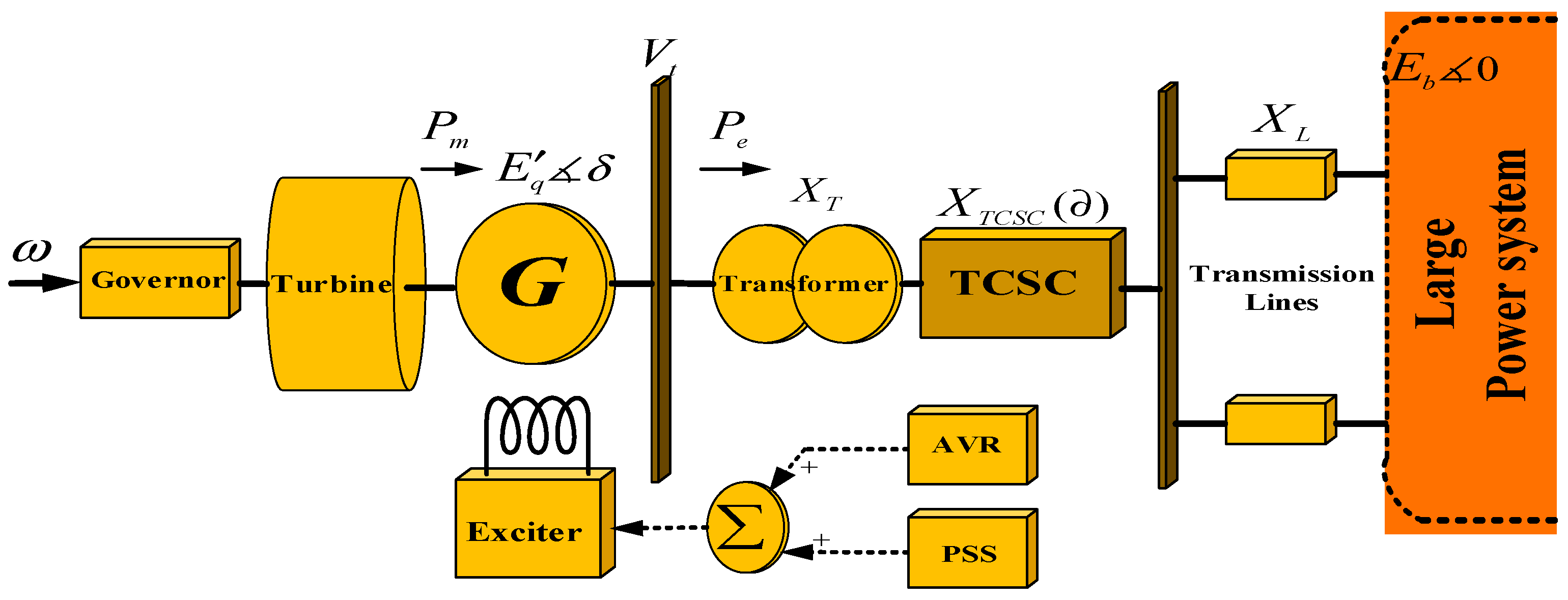
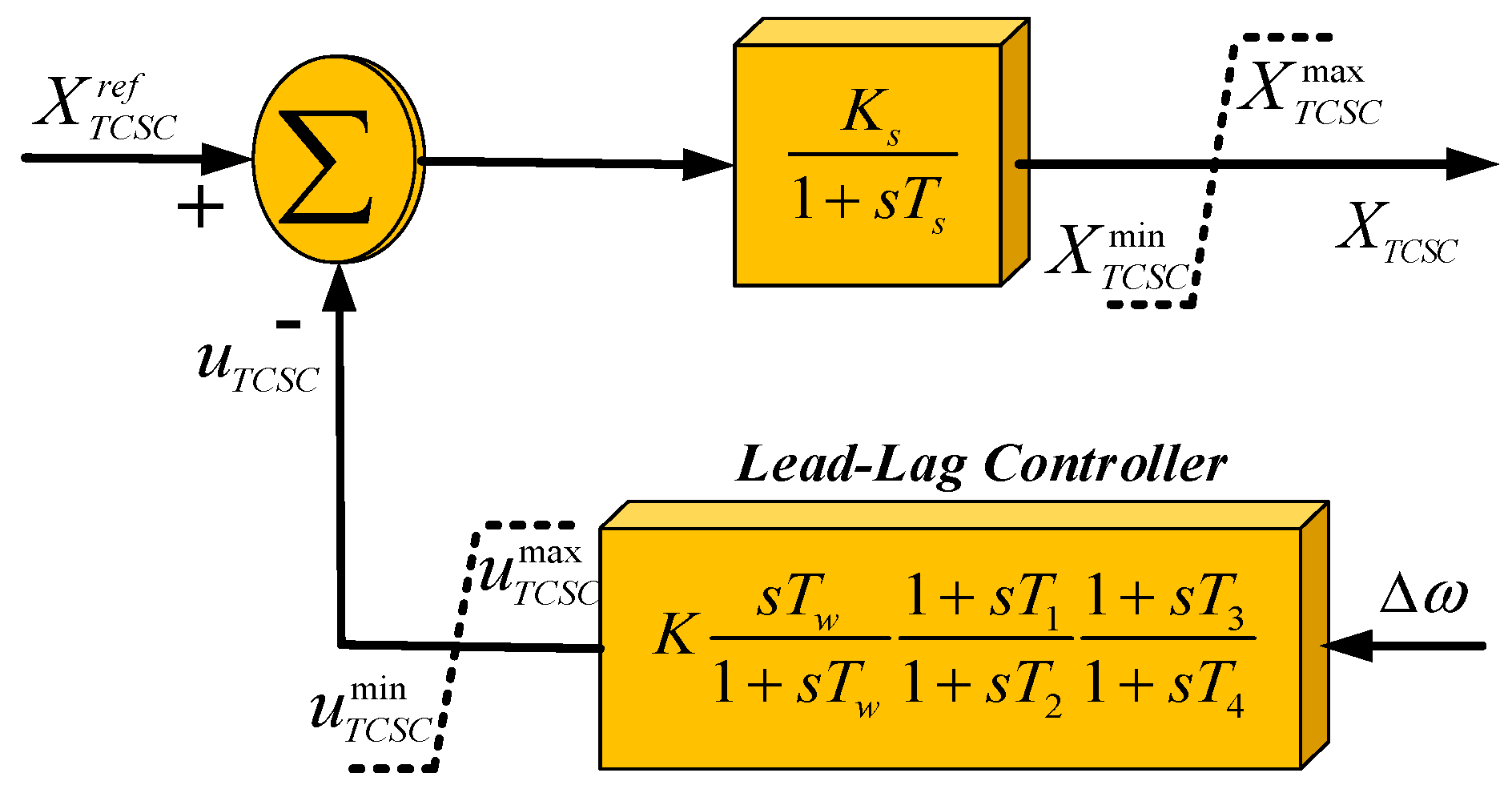
In this work, as depicted in Figure 1, a SMIB energy system furnished with a TCSC is employed. This power system is composed of a synchronous generator whose power is provided by a governor and a turbine and is excited using an external excitation system. The block diagram of a TCSC is presented in Figure 2.
The non-linear equations of the mentioned energy system equipped with a TCSC for the ith generator are as follows:
where ω is rotor angular speed of the synchronous generator (pu), δ is rotor angle of the synchronous generator (radians); Efd is the electro motive force (EMF) in the winding of excitation (pu); Eb is voltage of the infinite bus (pu); E’q is transient electro-motive force (EMF) in the quadratic axis of the generator (pu); f is power system synchronous frequency (Hz); T’d0 is direct axis open circuit transient time constant (s); H is inertial constant (s); KA is gain of the AVR (pu); TA is the AVR time constant (s); Ke is gain of the exciter (pu); Pm is the generator shaft mechanical power input (pu); Pe is active electrical power delivered by the generator (pu); uPSS is output signal of the PSS (pu); X’d is direct-axis component of the transient reactance of the generator (pu) and Xd is direct-axis components of the generator synchronous reactance (pu); Xq is quadrature-axis components of the generator synchronous reactance (pu); XTCSC is reactance of the TCSC (pu) and UTCSC is output signal of TCSC (pu); XL is reactance of the parallel transmission lines (pu); and XT is reactance of the transformer (pu).
4. Designing the Proposed Nonlinear PSS in a Power System with TCSC
In this part, the design procedure of a nonlinear PSS based on a synergetic control approach is proposed for a power system equipped with TCSC. To ameliorate the power system voltage regulation and transient stability, the output power (Pe) and the deviation of rotor velocity are considered as the inputs of PSS. Therefore, the macro-variable is defined as:
where Pref and ωref are reference values of the output power (Pe) and the angular velocity, and ξ1i is a constant coefficient, respectively. As these reference values form the control objectives, the selection of them can significantly impact the effectiveness of the control strategy. It is assumed that the control goals are carefully selected based on a thorough understanding of the power system’s requirements, objectives, and dynamic response. In designing a nonlinear controller according to the synergetic control approach, the objective is to force system falls in = 0 values [15,47]. By substituting Equation (26) in Equation (3), we have:
After simplification Equation (27) can be structured as follows:
Using chain differentiation rules and Equation (19), we have:
By substituting Equation (29) in Equation (28):
Consequently, the output of PSS and the input of the generator excitation system can be represented by substituting Equations (17) and (20) in Equation (30), as follows:
Due to Equation (31), UPSS forces state variables to hold in Equation (26). Based on this, the path approaches = 0 values with the constant coefficient of ξ1i, remains at = 0 afterward, and then the state trajectory is shown with Equation (27). These equations hold a linear relationship between the two system variables of Pe and ω. Therefore, it is causing a one-order reduction in the power system model which facilitates system stability.
While the proposed nonlinear synergetic stabilizer offers the advantage of order reduction and fewer control parameters, the sensitivity of control performance to these parameters remains challenging. Therefore, precise tuning of these parameters in the proposed control strategy is essential. Considering non-optimized control parameters can prove challenging in complex power systems due to the existence of system uncertainties and noise. Variations in load, generation, and disturbances within the power system can significantly affect stabilizer performance, and sensor inaccuracies further compound the issue. To address these challenges, an optimization framework is employed, utilizing the FOFMO algorithm, guided by FC principles. This algorithm adjusts the coefficients of the proposed nonlinear stabilizer by updating their position and velocity in fractional-order forms, enhancing the controller’s resilience and overall performance.
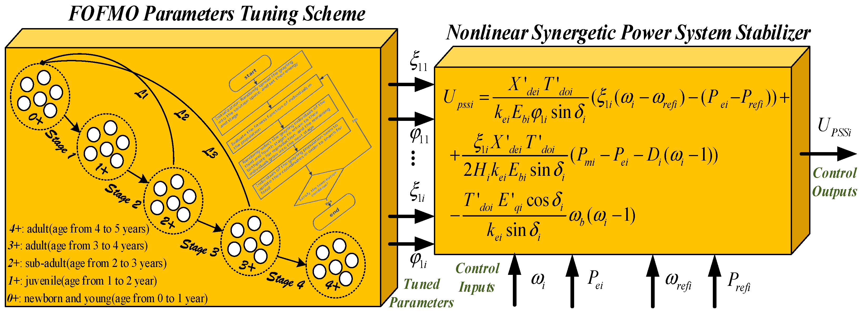
As illustrated in Equation (30), the appropriate selection of parameters ξ1i and φ1i (design parameters) plays a fundamental role in the performance and efficacy of the proposed control scheme. Therefore, as described in Section 2, the FOFMO algorithm has been used to optimally adjust the design parameters. To define a proper objective function, the integral of time absolute error (ITAE) is considered as a constrained optimization.
Objective function:
Decision variables:
Subject to:
The suggested control strategy is summarized in Figure 3.
Assuming that is minimum energy, indicates the fecundity restriction at each stage, describes the energy of the jth particle, and is the growth condition. The pseudo-code for the FOFMO procedure is illustrated in Algorithm 1.
| Algorithm 1: The pseudo-code of the FOFMO parameter tuning scheme. |
| I: set the population size and dimension () II: set the searching space S, iter = 1 III: set the position matrix , and historical position matrix IV: set energy of particles V: set number of iteration (numofiter) VI: set grows condition VII: calculate fitness function values VIII: while (iter < numofiter) do IX: for j = 1: do X: for κ = 1: do XI: calculate energy ()& fractional-order positions () XII: update the historical positions (Equation (13)) XIV: end for XVI: compute the fitness value of new positions () XV: if then XVII: , and = XVIII: increase energy by XIX: end if XX: consuming energy by XXI: if then XXII: , the grayling died. XXIII: end if XXIV: if then XXV: XXIV: else if then XXV: if then XXVI: create and immigrate offspring (Equation (14)), and set XXVII: else XXVIII: set XXIX: end if XXX: else if then XXXI: create and immigrate offspring (Equation (14)), and set XXXII: end if XXXIII: end for XXXIV: iter = iter + 1 XXXV: end while |
The presented FOFMO algorithm offers several advantages over other optimization algorithms. Firstly, FOFMO combines the benefits of swarm intelligence with fractional calculus, providing a unique approach to optimizing the parameters of the suggested nonlinear stabilizer. The use of fractional-order velocity updates in FOFMO enhances its exploitation capabilities, allowing it to find better solutions in a shorter time. Additionally, the adoption of Grünwald–Letnikov fractional derivatives provides more accurate modeling of system dynamics, which is especially beneficial for complex systems such as multi-machine power systems. Moreover, FOFMO leverages historical information to adjust particle positions and velocities, aiding in escaping local optima and achieving global optimization.
5. Simulation Results
In this section, to prove the efficacy of the suggested approach, numerical analysis is performed on a single machine connected to an infinitive bus power system and a two-area four-machine power system. The numerical evaluations are accomplished by MATLAB/Simulink software (Version R2022a).
Case I: Single-Machine Connected to Infinitive Bus Power System
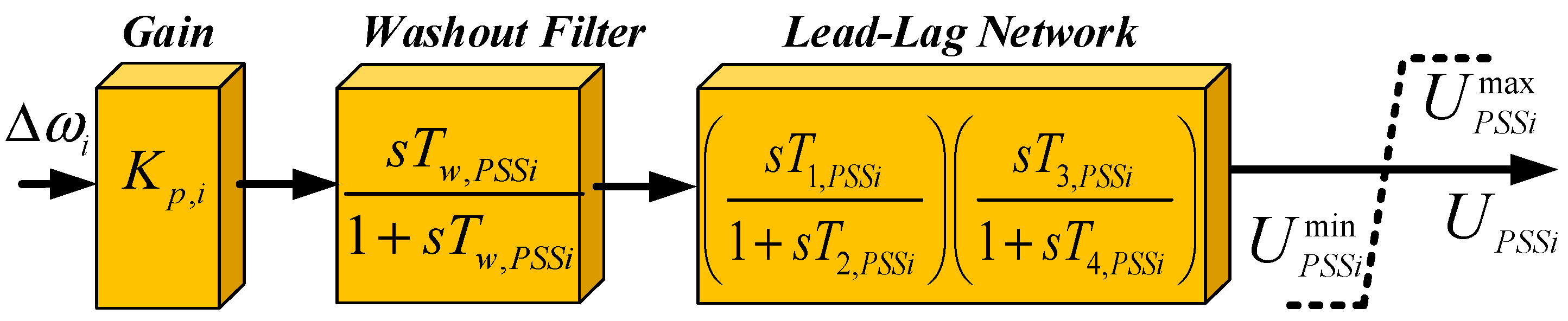
In this part, to analyze the SMIB power system under various disturbances, two faults of a step change in generator mechanical input power, and a three-phase short-circuit are applied to the system, and simulation results are obtained. To confirm the effectiveness of the proposed nonlinear fractional-order fish migration optimization-based PSS (NFOFMOPSS), simulation outcomes of NFOFMOPSS are analogized with these of the conventional PSS (CPSS), nonlinear synergetic-based PSS (NSPSS), and nonlinear particle swarm optimization-based PSS (NPSOPSS). A SMIB energy system equipped with a TCSC, which is illustrated in Figure 1, is employed for this numerical study. The parameters utilized in this case study are selected to be T’d0 = 6.55 s, H = 3.12 s, X’d = 0.314 pu, XT = 0.07 pu, Xq = 0.77 pu, Xd = 1.014 pu, f = 50 Hz, Xl = 0.325 pu, D = 2, while the initial conditions are chosen to be Pm0 = 1 pu, Vt0 = 1.05 pu, δ0 = 37.16°, ω0 = 1, E’q = 1.158 pu. The standard block diagram of the CPSS, containing the washout filter and the lead-lag compensation network, is represented in Figure 4, and their parameters are Kp = 10.5, Tw,PSS = 10 s, T1,PSS = 0.4 s, T2,PSS = 0.11 s, T3,PSS = 0.4 s, and T4,PSS = 0.11 s [15,29]. In addition, the characteristics of the excitation system can be described as Ke = 1, KA = 100, and TA = 0.01 s.
In this case study, the characteristics of NSPSS are selected to be ξ1 = 0.1, φ1 = 0.1 s, while the optimized control parameters of NPSOPSS and NFOFMOPSS are ξ1 = 0.0912, φ1 = 0.1175 s, and ξ1 = 0.0843, φ1 = 0.1219 s, respectively. The parameters of TCSC can be summarized as Ks = 1, Ts = 0.1 s, K = 80, Tw = 5 s, T1 = 0.5 s, T2 = 0.18 s, T3 = 0.5 s, and T4 = 0.18s. Note that the outputs of the excitation system and TCSC controller are restricted to ±6 pu and ±4 pu, respectively. In addition, in this case study, the upper and lower boundaries for the optimization framework’s constraints are ,, ,
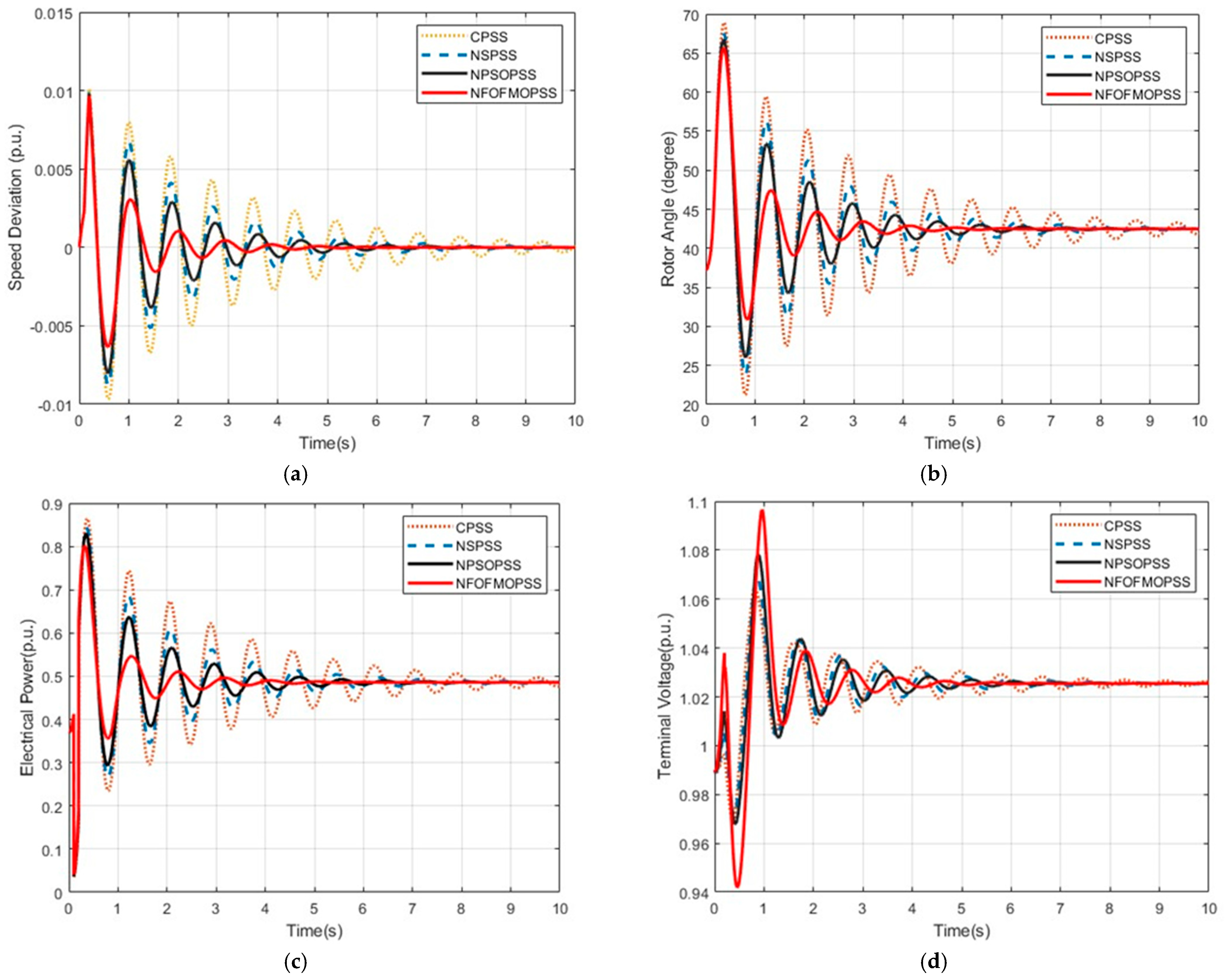
In the first scenario, to investigate the performance of suggested NFOFMOPSS in the large disturbances, a three-phase short-circuit fault has happened to the SMIB power system (on the infinite bus) at t = 0 s, and then one of the parallel transmission lines is switched off. When the disturbance is removed, at t = 0.1 s, the disconnected transmission line will be reconnected. The responses of the system to this disturbance are summarized in Figure 5. It can be discovered from the results that when the fault happened, the electrical power output dropped to near zero, and the terminal voltage increased to roughly 1.037 pu. Also, when the fault was removed, the system encountered a significant disturbance with the CPSS, whereas the oscillation was suppressed by the NFOFMOPSS. In addition, the oscillation was significantly diminished and dampened considerably more quickly with the proposed NFOFMOPSS in comparison with NSPSS and NPSOPSS.
The power angle eventually reached 42.5° after one of the transmission lines was switched off, and the terminal voltage was boosted. According to the simulation results, the suggested NFOFMOPSS is significantly more powerful in dampening oscillations than other mentioned solutions.
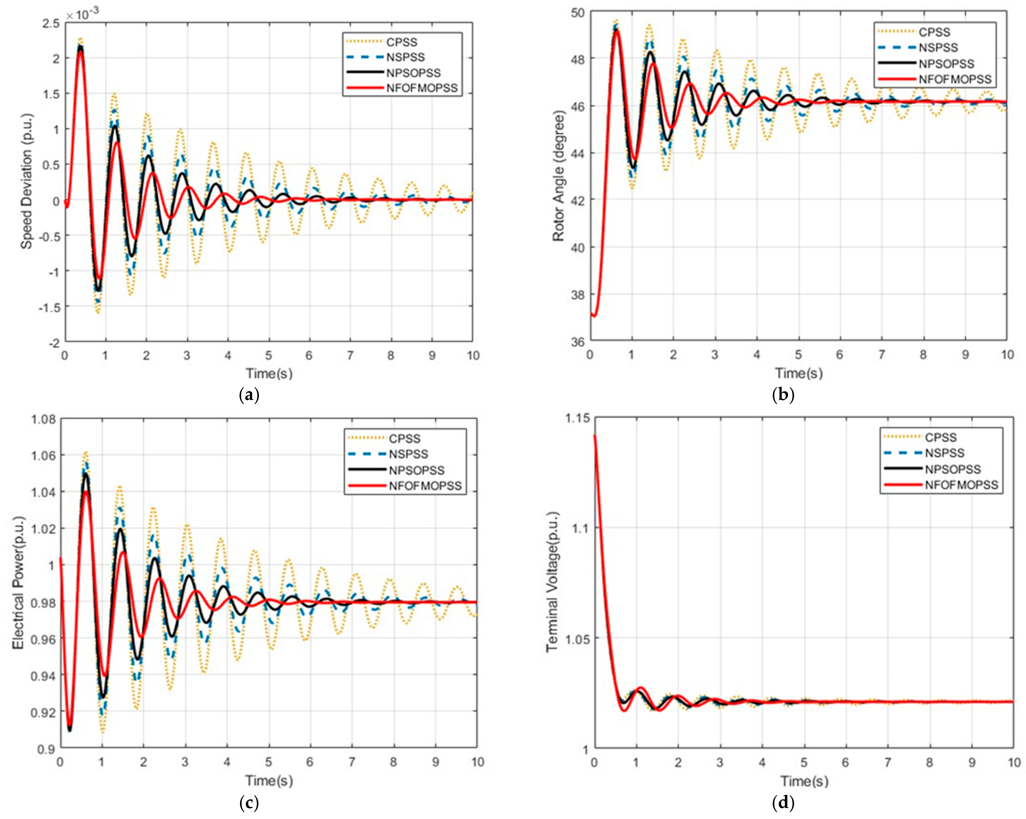
In the second scenario, the energy system responses to a 10% step change of the output mechanical power as a small disturbance are analyzed. This fault happened at t = 0 s, and simulation outcomes are depicted in Figure 6. The outcomes verify that the suggested NFOFMOPSS can furnish better control efficiency than the CPSS, NSPSS, and NPSOPSS in terms of voltage regulation, and damping rotational speed, output active power, and the rotor angle. Note that the voltage overshot was not lessened by the suggested NFOFMOPSS, as can be shown in Figure 6d. This is so that the PSS specifically dampens the fluctuation of the synchronous generator rotor angle while the AVR can keep the terminal voltage stable.
These simulation outcomes confirm that the advanced NFOFMOPSS not only can enhance the transient stability accuracy with a short rate of tracking references but also can damp the oscillations more effectively in comparison with other mentioned PSSs under large as well as small disturbances.
Case II: Two-Area Four-Machine Power System
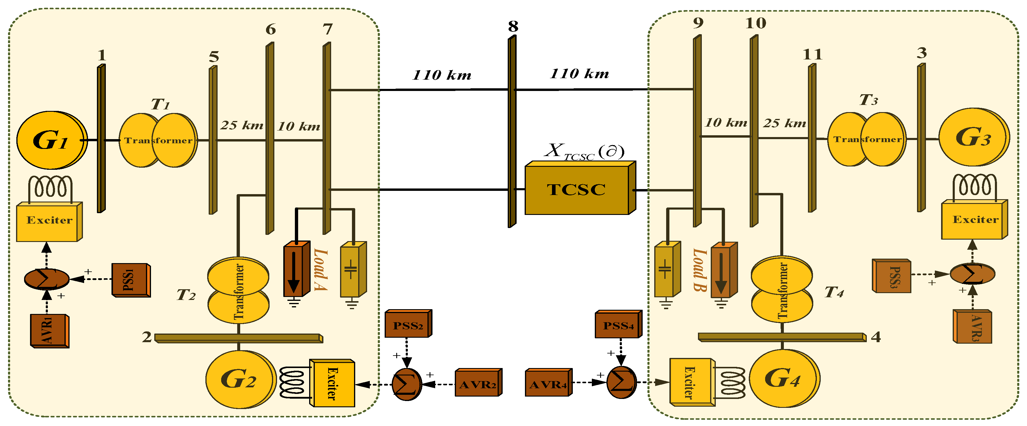
The single-line diagram of the two-area four-machine power system with TCSC where each area is equipped with two 900 MW and 20 KV generators is presented in Figure 7. Each generator is connected to the 230 KV transmission line via a transformer, and the transferred power from Area 1 to Area 2 equals 400 MV. These two areas are connected via two 220 km transmission lines, and each generator is equipped with an excitation system. In this multi-machine power system, a TCSC is placed on one of the 110 KM transmission lines between Buses 8 and 9. All power loads are considered by the regular impedance structure. Further information and detailed parameters of this two-area four-machine test system can be found in [5,29].
In this case, the parameters of CPSS for all generators are chosen to be Kpi = 20, Tw,PSSi = 10 s, T1,PSSi = 0.05 s, T2,PSSi = 0.02 s, T3,PSSi = 3 s, and T4,PSSi = 5.40 s [15,48]. The NSPSS established on each generator has identical parameters as ξ1i = 200, φ1i = 0.02 s. In addition, the optimized parameters of NPSOPSS and NFOFMOPSS are outlined in Table 1. In addition, in this case study, the upper and lower boundaries for the optimization framework’s constraints are ,, ,
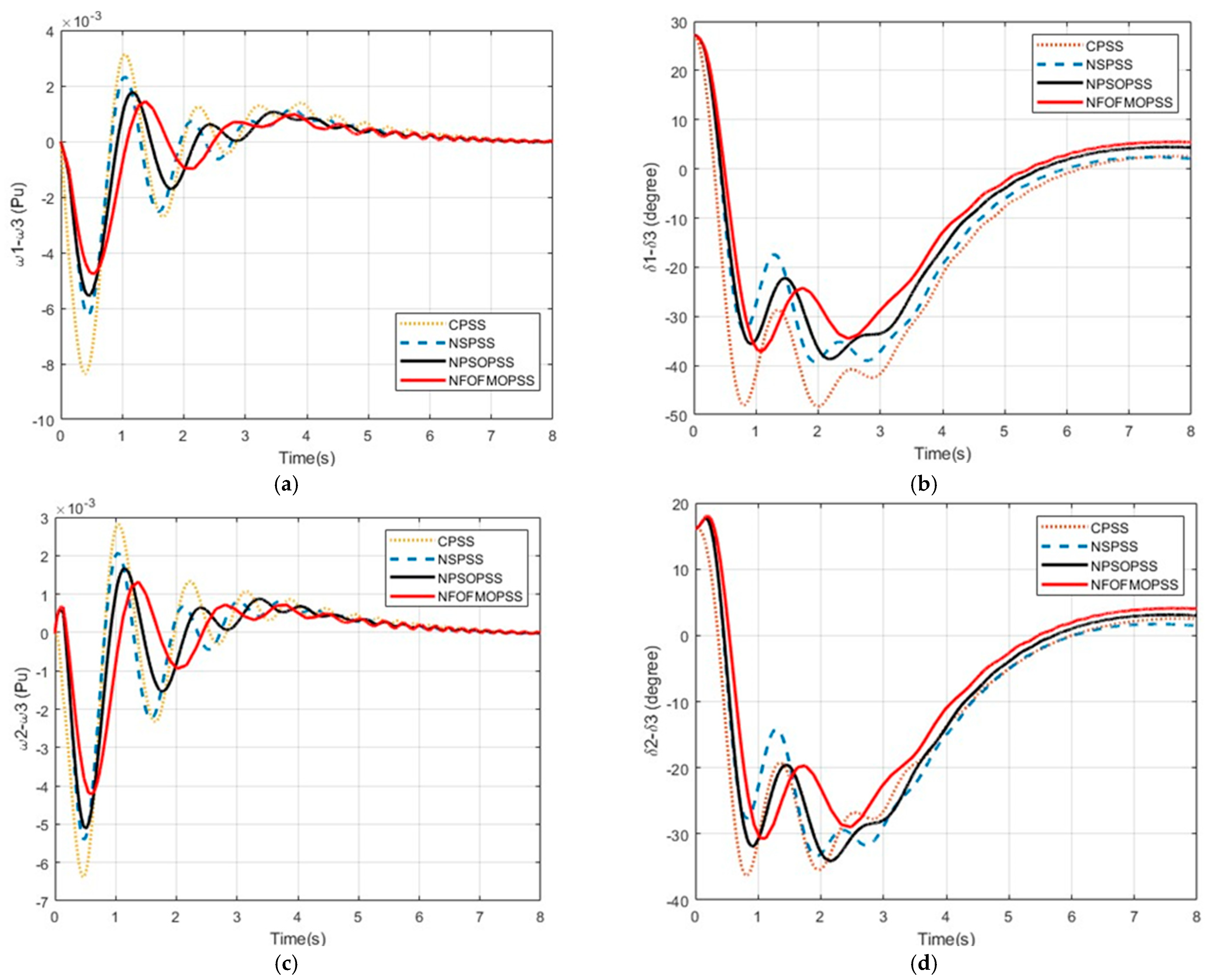
The multi-machine power system responses to a three-phase short-circuit fault occurring on one of the two 110 km lines between Buses 7 and 8 at t = 0 s are shown in Figure 8 (this fault remains in the system for 0.15 s and is then cleared). The simulation results demonstrate the superior and more effective performance of the system equipped with the presented NFOFMOPSS in terms of transient stability and damping oscillations compared with other cases (CPSS, NSPSS, and NPSOPSS). Figure 8 illustrates the relative rotor angle response between the first and third-generation units, the relative rotor speed response between the second and third synchronous generators, and the difference between the rotor angle responses of these generators. It can be seen that the results demonstrate significant improvements achieved by both the NPSOPSS and NFOFMOPSS in terms of system damping and settling time when compared to the NPSOPSS and the conventional PSS. Furthermore, it is evident that the NFOFMOPSS outperforms the NPSOPSS, confirming the effectiveness of the FOFMO parameter adaptation scheme. Specifically, the NFOFMOPSS excels in enabling the generator rotor angle and rotor speed to reach a new equilibrium state more rapidly while effectively damping oscillations, surpassing the performance of other controllers.
It can be concluded from the simulation outcomes that the proposed nonlinear controller equipped with the fractional-order fish migration tuning parameters scheme is effective in improving power system stability and terminal voltage regulation in the multi-machine case study.
6. Conclusions
This paper suggested a nonlinear fractional-order fish migration algorithm-based power system stabilizer for multi-machine energy systems equipped with FACTs devices. By directly adopting a nonlinear structure of the complicated energy system for control analysis, the presented solution addresses the issues with linear controllers. The synergetic control theory utilized in designing the suggested nonlinear controller offers asymptotic stability regarding the necessary operating modes, robustness to variations of power system components and their input variables, and immutability to load variations. Since the class of disturbance has an impact on the implementation of the controller by setting control parameters, it is impossible to concurrently maintain an acceptable damping effect, transient stability, and terminal voltage regulation in a large-scale energy system. Therefore, considering the influence of nonlinear controller characteristics on control performance, a parameter tuning scheme based on a fish migration algorithm and fractional calculus concepts is employed. Numerical studies are furnished on a single machine connected to an infinite-bus power system and a two-area four-machine power system, respectively. Numerical outcomes confirm that the suggested NFOFMOPSS performs better in terms of transient stability, damping oscillation, and terminal voltage regulation under a variety of operating conditions and disturbances than conventional PSS, synergetic PSS, and the NPSOPSS (which adjust parameters with PSO algorithms). Further, the suggested NFOFMOPSS can also be efficiently executed in a real energy system because it exclusively uses local input measurements and just simple controller settings must be established.
Author Contributions
Methodology, A.F. and B.A.; Software, A.F.; Validation, A.F. and B.A.; Writing—original draft, A.F.; Writing—review & editing, B.A.; Supervision, B.A. All authors have read and agreed to the published version of the manuscript.
Funding
This research received no external funding.
Data Availability Statement
Data are contained within the article.
Conflicts of Interest
The authors declare no conflict of interest.
References
- Sioshansi, R.; Denholm, P.; Arteaga, J.; Awara, S.; Bhattacharjee, S.; Botterud, A.; Cole, W.; Cortés, A.; Queiroz, A.d.; DeCarolis, J.; et al. Energy-Storage Modeling: State-of-the-Art and Future Research Directions. IEEE Trans. Power Syst. 2022, 37, 860–875. [Google Scholar] [CrossRef]
- Fathollahi, A.; Gheisarnejad, M.; Boudjadar, J.; Homayounzadeh, M.; Khooban, M.H. Optimal Design of Wireless Charging Electric Buses-Based Machine Learning: A Case Study of Nguyen-Dupuis Network. IEEE Trans. Veh. Technol. 2023, 72, 8449–8458. [Google Scholar] [CrossRef]
- Fathollahi, A.; Gheisarnejad, M.; Andresen, B.; Farsizadeh, H.; Khooban, M.H. Robust Artificial Intelligence Controller for Stabilization of Full-Bridge Converters Feeding Constant Power Loads. IEEE Trans. Circuits Syst. II Express Briefs 2023, 70, 3504–3508. [Google Scholar] [CrossRef]
- Rezaei, M.A.; Fathollahi, A.; Rezaei, S.; Hu, J.; Gheisarnejad, M.; Teimouri, A.R.; Rituraj, R.; Mosavi, A.H.; Khooban, M.H. Adaptation of a Real-Time Deep Learning Approach With an Analog Fault Detection Technique for Reliability Forecasting of Capacitor Banks Used in Mobile Vehicles. IEEE Access 2022, 10, 132271–132287. [Google Scholar] [CrossRef]
- Wang, Y.; Wang, L.; Jiang, Q. Sustained Oscillation Analysis of VSC Considering High-Order Oscillation Components. IEEE Trans. Power Syst. 2022, 37, 2471–2474. [Google Scholar] [CrossRef]
- Yildirim, B.; Razmi, P.; Fathollahi, A.; Gheisarnejad, M.; Khooban, M.H. Neuromorphic deep learning frequency regulation in stand-alone microgrids. Appl. Soft Comput. 2023, 144, 110418. [Google Scholar] [CrossRef]
- Øyvang, T.; Nøland, J.K.; Sharma, R.; Hegglid, G.J.; Lie, B. Enhanced Power Capability of Generator Units for Increased Operational Security Using NMPC. IEEE Trans. Power Syst. 2020, 35, 1562–1571. [Google Scholar] [CrossRef]
- Li, C.; Yang, Y.; Li, Y.; Cao, Y.; Murashov, I.; Xu, J.; Aleshina, A.; Blaabjerg, F. Generalized Stabilizer-Oriented Design for GFVSG Integrated Into Weak-Stiffness Power Networks. IEEE Trans. Power Syst. 2022, 37, 4958–4961. [Google Scholar] [CrossRef]
- Shahgholian, G.; Fattollahi, A. Improving power system stability using transfer function: A comparative analysis. Eng. Technol. Appl. Sci. Res. 2017, 7, 1946–1952. [Google Scholar] [CrossRef]
- Jankee, P.; Oyedokun, D.T.; Chisepo, H.K. Dynamic response of power systems with real GICs: Impact on generator excitation control. IEEE Trans. Power Deliv. 2022, 37, 4911–4922. [Google Scholar] [CrossRef]
- Sabo, A.; Wahab, N.I.A.; Othman, M.L.; Jaffar, M.Z.A.B.M.; Acikgoz, H.; Nafisi, H.; Shahinzadeh, H. Artificial Intelligence-Based Power System Stabilizers for Frequency Stability Enhancement in Multi-Machine Power Systems. IEEE Access 2021, 9, 166095–166116. [Google Scholar] [CrossRef]
- Boukarim, G.E.; Shaopeng, W.; Chow, J.H.; Taranto, G.N.; Martins, N. A comparison of classical, robust, and decentralized control designs for multiple power system stabilizers. IEEE Trans. Power Syst. 2000, 15, 1287–1292. [Google Scholar] [CrossRef]
- Saleem, B.; Badar, R.; Manzoor, A.; Judge, M.A.; Boudjadar, J.; Islam, S.U. Fully Adaptive Recurrent Neuro-Fuzzy Control for Power System Stability Enhancement in Multi Machine System. IEEE Access 2022, 10, 36464–36476. [Google Scholar] [CrossRef]
- Lala, J.A.O.; Gallardo, C.F. Adaptive Tuning of Power System Stabilizer Using a Damping Control Strategy Considering Stochastic Time Delay. IEEE Access 2020, 8, 124254–124264. [Google Scholar] [CrossRef]
- Fathollahi, A.; Kargar, A.; Yaser Derakhshandeh, S. Enhancement of power system transient stability and voltage regulation performance with decentralized synergetic TCSC controller. Int. J. Electr. Power Energy Syst. 2022, 135, 107533. [Google Scholar] [CrossRef]
- Sreedivya, K.M.; Aruna Jeyanthy, P.; Devaraj, D. Improved Design of Interval Type-2 Fuzzy based Wide Area Power System Stabilizer for Inter-area Oscillation Damping. Microprocess. Microsyst. 2021, 83, 103957. [Google Scholar] [CrossRef]
- Fattollahi, A.; Dehghani, M.; Yousefi, M.R. Analysis and Simulation Dynamic Behavior of Power System Equipped with PSS and Excitation System Stabilizer. Signal Process. Renew. Energy 2022, 6, 99–111. [Google Scholar]
- Guo, K.; Qi, Y.; Yu, J.; Frey, D.; Tang, Y. A Converter-Based Power System Stabilizer for Stability Enhancement of Droop-Controlled Islanded Microgrids. IEEE Trans. Smart Grid 2021, 12, 4616–4626. [Google Scholar] [CrossRef]
- Shahgholian, G.; Mardani, E.; Fattollahi, A. Impact of PSS and STATCOM devices to the dynamic performance of a multi-machine power system. Eng. Technol. Appl. Sci. Res. 2017, 7, 2113–2117. [Google Scholar] [CrossRef]
- Rahmatian, M.; Seyedtabaii, S. Multi-machine optimal power system stabilizers design based on system stability and nonlinearity indices using Hyper-Spherical Search method. Int. J. Electr. Power Energy Syst. 2019, 105, 729–740. [Google Scholar] [CrossRef]
- Zhang, Z.; Zhao, X.; Fu, L.; Edrah, M. Stability and Dynamic Analysis of the PMSG-Based WECS With Torsional Oscillation and Power Oscillation Damping Capabilities. IEEE Trans. Sustain. Energy 2022, 13, 2196–2210. [Google Scholar] [CrossRef]
- Oshnoei, S.; Aghamohammadi, M.R.; Oshnoei, S.; Sahoo, S.; Fathollahi, A.; Khooban, M.H. A novel virtual inertia control strategy for frequency regulation of islanded microgrid using two-layer multiple model predictive control. Appl. Energy 2023, 343, 121233. [Google Scholar] [CrossRef]
- Mosayebi, M.; Fathollahi, A.; Gheisarnejad, M.; Farsizadeh, H.; Khooban, M.H. Smart emergency EV-to-EV portable battery charger. Inventions 2022, 7, 45. [Google Scholar] [CrossRef]
- Bouchama, Z.; Essounbouli, N.; Harmas, M.N.; Hamzaoui, A.; Saoudi, K. Reaching phase free adaptive fuzzy synergetic power system stabilizer. Int. J. Electr. Power Energy Syst. 2016, 77, 43–49. [Google Scholar] [CrossRef]
- Wang, J.; Liu, L.; Liu, C.; Liu, J. Fixed-Time Synergetic Control for a Seven-Dimensional Chaotic Power System Model. Int. J. Bifurc. Chaos 2019, 29, 1950130. [Google Scholar] [CrossRef]
- Anderson, J.A.; Haider, M.; Bortis, D.; Kolar, J.W.; Kasper, M.; Deboy, G. New Synergetic Control of a 20 kW Isolated VIENNA Rectifier Front-End EV Battery Charger. In Proceedings of the 2019 20th Workshop on Control and Modeling for Power Electronics (COMPEL), Toronto, ON, Canada, 17–20 June 2019; pp. 1–8. [Google Scholar]
- Djennoune, S.; Bettayeb, M. Optimal synergetic control for fractional-order systems. Automatica 2013, 49, 2243–2249. [Google Scholar] [CrossRef]
- Mokhliss, H.; El-Amiri, A.; Rais, K. Estimation of five parameters of photovoltaic modules using a synergetic control theory approach. J. Comput. Electron. 2019, 18, 241–250. [Google Scholar] [CrossRef]
- Zhao, P.; Yao, W.; Wen, J.; Jiang, L.; Wang, S.; Cheng, S. Improved synergetic excitation control for transient stability enhancement and voltage regulation of power systems. Int. J. Electr. Power Energy Syst. 2015, 68, 44–51. [Google Scholar] [CrossRef]
- Kolesnikov, A.A. Introduction of Synergetic Control. In Proceedings of the 2014 American Control Conference, Portland, OR, USA, 4–6 June 2014; pp. 3013–3016. [Google Scholar]
- Bezuglov, A.; Kolesnikov, A.; Kondratiev, I.; Juan, V. Synergetic Control Theory Approach for Solving Systems of Nonlinear Equations. In Proceedings of the WMSCI 2005-The 9th World Multi-Conference on Systemics, Cybernetics and Informatics, Proceedings, Orlando, FL, USA, 10–13 July 2005; pp. 121–126. [Google Scholar]
- Lu, Q.; Sun, Y.; Mei, S. Nonlinear Control Systems and Power System Dynamics; Springer Science & Business Media: Berlin/Heidelberg, Germany, 2001; Volume 10. [Google Scholar]
- Chatterjee, K.; Samanta, S.; Chaudhuri, N.R. Insights Into Dissipating Energy-Based Source/Sink Characterization of TCSC and STATCOM for Low-Frequency Oscillations. IEEE Trans. Power Deliv. 2022, 38, 1426–1439. [Google Scholar] [CrossRef]
- Das, S.; Panigrahi, B.K.; Jaiswal, P.K. Qualitative Assessment of Power Swing for Enhancing Security of Distance Relay in a TCSC-Compensated Line. IEEE Trans. Power Deliv. 2021, 36, 223–234. [Google Scholar] [CrossRef]
- Prakash, A.; Kumar, K.; Parida, S.K. A Modal Transformation Approach to Design Reduced Order Functional Observer-Based WADC for Low-Frequency Oscillations. IEEE Trans. Power Syst. 2022, 38, 3593–3604. [Google Scholar] [CrossRef]
- Abrazeh, S.; Mohseni, S.R.; Zeitouni, M.J.; Parvaresh, A.; Fathollahi, A.; Gheisarnejad, M.; Khooban, M.H. Virtual Hardware-in-the-Loop FMU Co-Simulation Based Digital Twins for Heating, Ventilation, and Air-Conditioning (HVAC) Systems. IEEE Trans. Emerg. Top. Comput. Intell. 2023, 7, 65–75. [Google Scholar] [CrossRef]
- Chai, Q.-W.; Chu, S.-C.; Pan, J.-S.; Zheng, W.-M. Applying Adaptive and Self Assessment Fish Migration Optimization on Localization of Wireless Sensor Network on 3-D Te rrain. J. Inf. Hiding Multim. Signal Process. 2020, 11, 90–102. [Google Scholar]
- Pan, J.-S.; Tsai, P.-W.; Liao, Y.-B. Fish Migration Optimization Based on the Fishy Biology. In Proceedings of the 2010 Fourth International Conference on Genetic and Evolutionary Computing, Shenzhen, China, 13–15 December 2010; pp. 783–786. [Google Scholar]
- Povstenko, Y. Thermoelasticity that uses fractional heat conduction equation. J. Math. Sci. 2009, 162, 296–305. [Google Scholar] [CrossRef]
- Boudjemaa, R.; Oliva, D.; Ouaar, F. Fractional Lévy flight bat algorithm for global optimisation. Int. J. Bio Inspired Comput. 2020, 15, 100–112. [Google Scholar] [CrossRef]
- Couceiro, M.S.; Rocha, R.P.; Ferreira, N.; Machado, J. Introducing the fractional-order Darwinian PSO. Signal Image Video Process. 2012, 6, 343–350. [Google Scholar] [CrossRef]
- Yousri, D.; Mirjalili, S. Fractional-order cuckoo search algorithm for parameter identification of the fractional-order chaotic, chaotic with noise and hyper-chaotic financial systems. Eng. Appl. Artif. Intell. 2020, 92, 103662. [Google Scholar] [CrossRef]
- Mousavi, Y.; Alfi, A.; Kucukdemiral, I.B. Enhanced fractional chaotic whale optimization algorithm for parameter identification of isolated wind-diesel power systems. IEEE Access 2020, 8, 140862–140875. [Google Scholar] [CrossRef]
- Pan, J.-S.; Hu, P.; Chu, S.-C. Binary fish migration optimization for solving unit commitment. Energy 2021, 226, 120329. [Google Scholar] [CrossRef]
- Guo, B.; Zhuang, Z.; Pan, J.S.; Chu, S.C. Optimal Design and Simulation for PID Controller Using Fractional-Order Fish Migration Optimization Algorithm. IEEE Access 2021, 9, 8808–8819. [Google Scholar] [CrossRef]
- Chiranjeevi, T.; Biswas, R.K. Computational Method Based on Reflection Operator for Solving a Class of Fractional Optimal Control Problem. Procedia Comput. Sci. 2020, 171, 2030–2039. [Google Scholar] [CrossRef]
- Antivachis, M.; Anderson, J.A.; Bortis, D.; Kolar, J.W. Analysis of a synergetically controlled two-stage three-phase DC/AC buck-boost converter. CPSS Trans. Power Electron. Appl. 2020, 5, 34–53. [Google Scholar] [CrossRef]
- Das, T.K.; Venayagamoorthy, G.K.; Aliyu, U.O. Bio-inspired algorithms for the design of multiple optimal power system stabilizers: SPPSO and BFA. IEEE Trans. Ind. Appl. 2008, 44, 1445–1457. [Google Scholar] [CrossRef]
Figure 1.
SMIB power system with a TCSC.

Figure 2.
Block diagram of TCSC control scheme.

Figure 3.
The summarized control strategy.

Figure 4.
Block diagram of conventional PSS.

Figure 5.
SMIB power system responses to a three-phase short-circuit fault on the infinite bus. (a) Speed de-viation response (three-phase short-circuit fault), (b) Rotor angle response (three-phase short-circuit fault), (c) active electrical power response (three-phase short-circuit fault), (d) terminal voltage response (three-phase short-circuit fault).

Figure 6.
SMIB power system responses to a 10% step change of mechanical power output. (a) Speed devia-tion response (10% step change of mechanical power), (b) rotor angle response (10% step change of mechanical power), (c) active electrical power response (10% step change of mechanical power), (d) terminal voltage response (10% step change of mechanical power).

Figure 7.
Single line diagram of the two-area four-machine power system with TCSC.

Figure 8.
Multi-machine power system response to a three-phase short-circuit fault. (a) Relative rotor speed response ω13. (b) Relative rotor angle response δ13. (c) Relative rotor speed response ω23. (d) Relative rotor angle response δ23.
Figure 8.
Multi-machine power system response to a three-phase short-circuit fault. (a) Relative rotor speed response ω13. (b) Relative rotor angle response δ13. (c) Relative rotor speed response ω23. (d) Relative rotor angle response δ23.


Table 1.
The system parameters utilized in Case II.
| Parameters | G1 | G2 | G3 | G4 |
|---|---|---|---|---|
| NPSOPSS | ξ11 = 207.1 | ξ11 = 182.2 | ξ11 = 214.8 | ξ11 = 238.4 |
| φ11 = 0.021 s | φ11 = 0.020 s | φ11 = 0.0191 s | φ11 = 0.020 s | |
| NFOFMOPSS | ξ11 = 273.2 | ξ11 = 238.8 | ξ11 = 227.6 | ξ11 = 237.1 |
| φ11 = 0.011 s | φ11 = 0.012 s | φ11 = 0.015 s | φ11 = 0.012 s |
Disclaimer/Publisher’s Note: The statements, opinions and data contained in all publications are solely those of the individual author(s) and contributor(s) and not of MDPI and/or the editor(s). MDPI and/or the editor(s) disclaim responsibility for any injury to people or property resulting from any ideas, methods, instructions or products referred to in the content. |
© 2023 by the authors. Licensee MDPI, Basel, Switzerland. This article is an open access article distributed under the terms and conditions of the Creative Commons Attribution (CC BY) license (https://creativecommons.org/licenses/by/4.0/).
Share and Cite
MDPI and ACS Style
Fathollahi, A.; Andresen, B. Multi-Machine Power System Transient Stability Enhancement Utilizing a Fractional Order-Based Nonlinear Stabilizer. Fractal Fract. 2023, 7, 808. https://doi.org/10.3390/fractalfract7110808
AMA Style
Fathollahi A, Andresen B. Multi-Machine Power System Transient Stability Enhancement Utilizing a Fractional Order-Based Nonlinear Stabilizer. Fractal and Fractional. 2023; 7(11):808. https://doi.org/10.3390/fractalfract7110808
Chicago/Turabian StyleFathollahi, Arman, and Björn Andresen. 2023. "Multi-Machine Power System Transient Stability Enhancement Utilizing a Fractional Order-Based Nonlinear Stabilizer" Fractal and Fractional 7, no. 11: 808. https://doi.org/10.3390/fractalfract7110808