
Design and Implementation of a Digital Twin System for Log Rotary Cutting Optimization

1
School of Technology, Beijing Forestry University, Beijing 100083, China
2
Key Lab of State Forestry Administration for Forestry Equipment and Automation, Beijing 100083, China
*
Author to whom correspondence should be addressed.
Future Internet 2024, 16(1), 7; https://doi.org/10.3390/fi16010007
Submission received: 6 December 2023
/
Revised: 21 December 2023
/
Accepted: 22 December 2023
/
Published: 25 December 2023
(This article belongs to the Special Issue Digital Twins in Intelligent Manufacturing)
Abstract
:To address the low level of intelligence and low utilization of logs in current rotary cutting equipment, this paper proposes a digital twin-based system for optimizing the rotary cutting of logs using a five-dimensional model of digital twins. The system features a log perception platform to capture three-dimensional point cloud data, outlining the logs’ contours. Utilizing the Delaunay3D algorithm, this model performs a three-dimensional reconstruction of the log point cloud, constructing a precise digital twin. Feature information is extracted from the point cloud using the least squares method. Processing parameters, determined through the kinematic model, are verified in rotary cutting simulations via Bool operations. The system’s efficacy has been substantiated through experimental validation, demonstrating its capability to output specific processing schemes for irregular logs and to verify these through simulation. This approach notably improves log recovery rates, decreasing volume error from 12.8% to 2.7% and recovery rate error from 23.5% to 5.7% The results validate the efficacy of the proposed digital twin system in optimizing the rotary cutting process, demonstrating its capability not only to enhance the utilization rate of log resources but also to improve the economic efficiency of the factory, thereby facilitating industrial development.
1. Introduction
In the context of Industry 4.0’s evolution, the sustained and deep integration of information technology into traditional manufacturing sectors has ushered the wood processing industry into the “Intelligent Era”. At the historical intersection of a new round of technological revolution, industrial transformation, and China’s accelerated high-quality development, and in the face of the new requirements of the “dual-carbon” strategy, digital twin technology has become an important means for further intelligent upgrading of China’s wood processing industry [1].
Digital twins [2] are digital representations of real-world entities or systems, composed of physical objects and their virtual entities, twin data, and application services. Digital twins diverge from mere modeling and simulation, encompassing these methodologies as components of a more comprehensive technological ecosystem. Similar terminologies, however, denote distinct concepts, such as ‘digital models’, ‘digital shadows’, ‘digital twins’, and ‘digital predictions’. A ‘digital model’ lacks real-time linkage with physical entities, akin to simulations and mathematical models; a ‘digital shadow’ plays a crucial role in real-time monitoring, where changes in the state of a physical entity instantaneously alter the state of its digital counterpart, constituting unidirectional real-time data communication from a physical to a digital space; a ‘digital twin’ involves bidirectional real-time data communication between physical and digital realms and utilizes methodologies such as big data and machine learning in cyberspace for further analysis and prediction; and a ‘digital twin prediction’ represents a digital replica of a physical entity, functioning through bidirectional real-time data communication in cyberspace [3]. Digital twins can be used to design and optimize products and processes more quickly and accurately, improve production efficiency, and reduce costs and risks. They have been widely used in various industries, including the manufacturing [4], automotive [5], medical [6], smart city [7], smart building [8], and other industries. Scholars have gradually attempted to apply digital twin technology to the wood processing industry. For example, Jean Werya proposed a simulation-based decision-making framework in 2017 to ensure order profitability, analyze required raw materials and equipment, and determine when to produce based on factory order volumes [9]. Morin proposed using six characteristics of logs to train multiple machine learning models and applied them to MILP models to optimize log allocation for sawmills in 2020 [10]. Chen Zhijie et al. established a digital twin model of the wood side plate production process using VSM and FlexSim simulation models in 2022, effectively improving the production process and using computer vision methods to complete wood quality and thickness detection [11]. As discussed previously, the focus of most research papers is on issues related to wood processing scheduling and finished product inspection. However, the real challenge in the wood processing industry lies in the high heterogeneity of raw materials (logs) characterized by varying shapes and qualities of different logs [12]. This necessitates the adoption of distinct processing approaches for different logs to maximize resource utilization. Therefore, this paper applies digital twin technology in the wood processing workflow to achieve the aforementioned functionalities.
The log rotary cutting process includes log centering, log debarking, and veneer peeling. The log is centered to find the optimal clamping point, and the outer waste material is removed by the log debarker. Finally, it is processed into veneers in the veneer peeling machine. The log debarker adopts a card-axis processing method, and the veneer peeling adopts a card-free axis processing method. The centering result is one of the important processes in the production process for card-axis processing. In China’s rotary-cutting production line, log centering is mainly achieved through mechanical centering and halo centering. Neither centering method is suitable for logs with irregular shapes. Compared with digital centering technology, the log recovery rate is reduced by 10~15%, and the card-free processing method is a time-varying nonlinear system. Currently, most equipment adopts open-loop control, which cannot guarantee the quality of veneers. Therefore, to address the low level of intelligence and low utilization of logs in China’s rotary cutting production line, this paper establishes a digital twin system for log rotary cutting optimization based on a five-dimensional model of the digital twin, which can autonomously analyze log feature data and derive targeted processing schemes [13]. The system not only includes a digital log-centering machine as the physical entity for the complete acquisition of the log’s outer contour but also encompasses virtual entities of other equipment involved in the rotary-cutting process. Through the service system, the system can analyze the optimal centering position of the log based on log feature data and perform real-time calculations for the processing parameters of the log debarker, as well as the veneer peeling machine. These calculations are then verified through simulation using virtual entities. This approach effectively confirms the optimal method for log rotary cutting, improves log utilization and enhances the automation level of the log rotary cutting production line.
2. Materials and Methods
2.1. Five-Dimensional Model
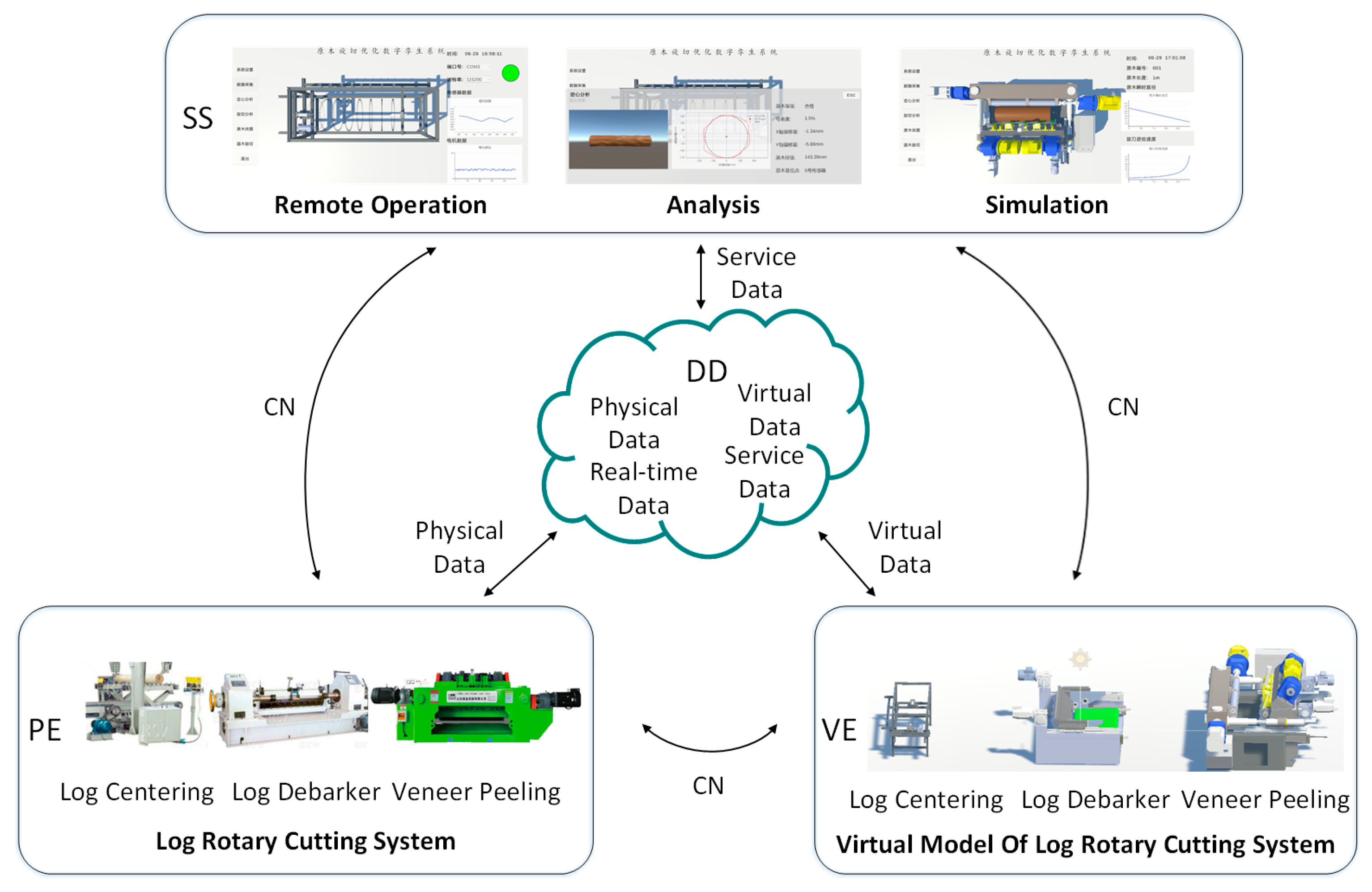
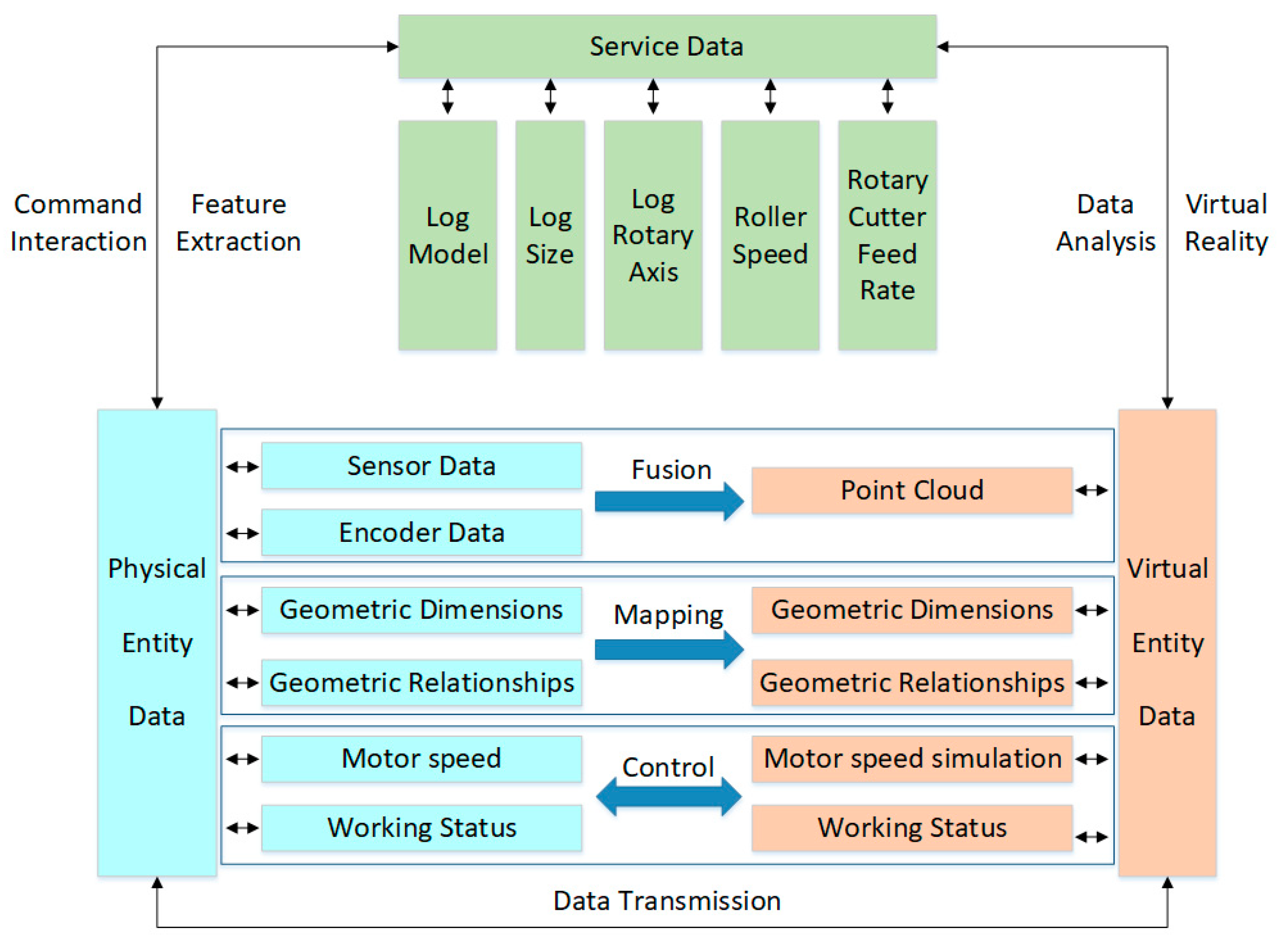
The process of rotary cutting of logs includes operations such as log centering, log debarking, and veneer peeling. The procedure involves locating the optimal clamping point through the log-centering process, removing outer waste materials through the log debarker, and ultimately processing them into veneers using the veneer peeling machine. The equipment involved in each step of the log rotary cutting process includes the log centering machine, log debarker, and veneer peeling machine. In response to the low level of intelligence and poor log utilization in log rotary cutting equipment, this paper proposes a digital twin system for log rotary cutting based on the five-dimensional model of digital twins (MDT) [14], as shown in (1). The system design is illustrated in Figure 1, consisting of five components: the physical entity (PE) of the log rotary cutting system, the virtual entity (VE) of the log rotary cutting system, the digital twin data (DD) generated by the integration of the physical entity and services, the service system (SS) that supports cutting analysis and simulation, and the connection of data (CN) and information between the components. The digital twin data includes the physical data of the log rotary cutting system during actual operation, data collected by sensors, virtual data generated by the log rotary cutting system model during simulation, and service data generated by the service system.
This paper aims to establish a digital twin system for log peeling optimization. By obtaining log point cloud information, it can independently confirm the optimal log peeling plan and conduct simulation verification of the log peeling plan in the twin space.
2.1.1. Materials
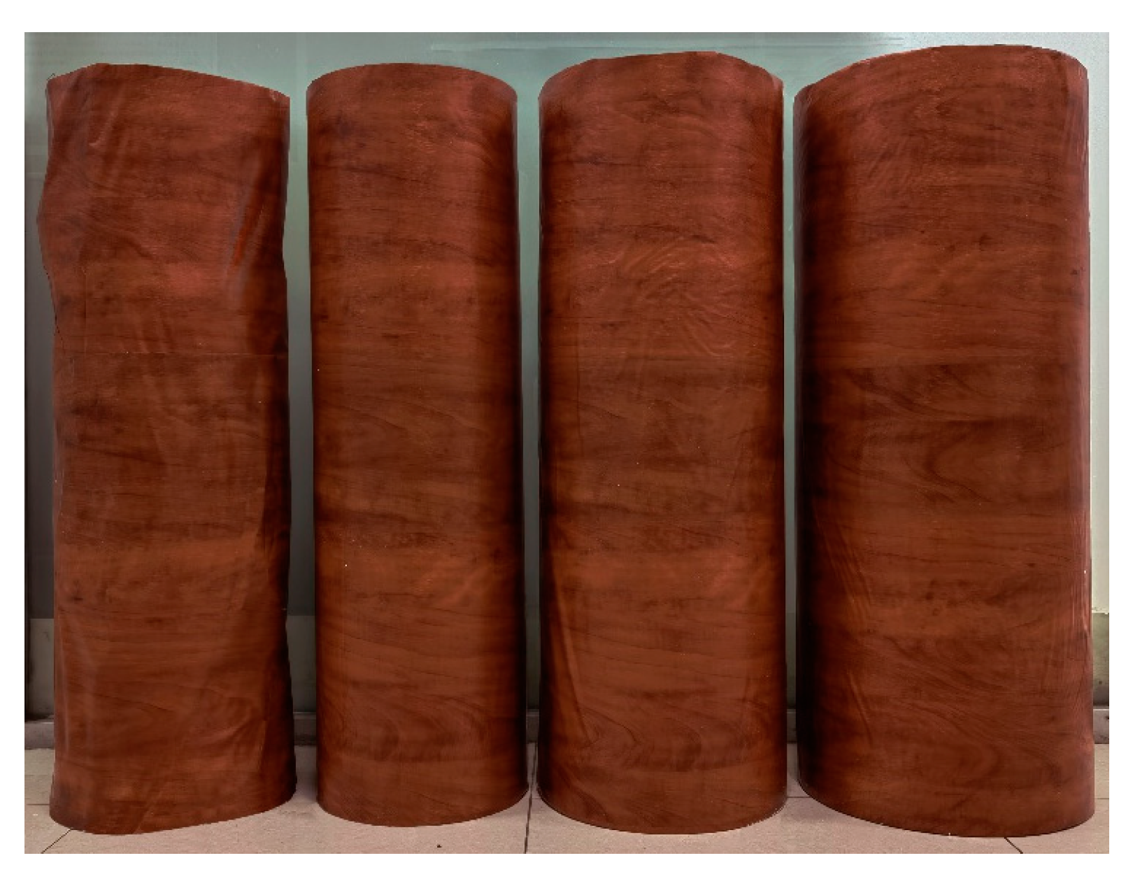
Due to the inconvenience of experimenting with real tree logs, this article designs models using SolidWorks software according to the processing size range of logs using a certain company’s equipment and uses CNC lathe machining for experimental materials, including standard cylindrical logs of 150 mm, 175 mm, 200 mm, and an irregular log. Among them, to ensure the simulation of the irregular shape of real logs, the irregular logs are created in SolidWorks software by scanning and patterning eight random closed shapes. The materials are shown in Figure 2.
2.1.2. Physical Entity of the Log Cutting System
The physical entity refers to the actual log rotary-cutting line in the physical workshop, including equipment such as the log centering machine, log debarker, and veneer peeling machine. Additionally, the physical entity of the log rotary cutting system includes various sensors that support the collection and transmission of information such as the log point cloud data, motor speed, and status information. The log rotary cutting system is capable of uploading data and information, as well as executing instructions. It provides support for real-time interconnection and iterative interaction between physical and virtual entities.
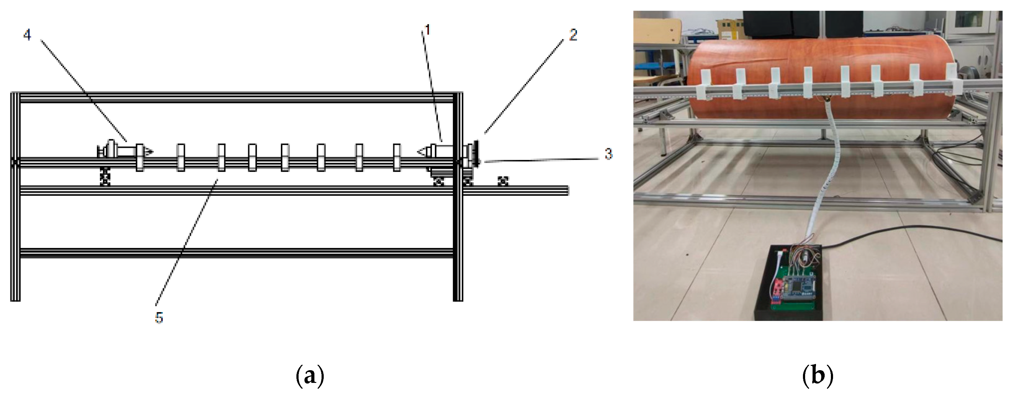
In this study, the physical entity specifically refers to the log-centering machine experimental platform (Figure 3). The platform consists of a head-and-tail card shaft mechanism for log clamping, with a motor driving the rotation through a synchronous belt pulley. Control is implemented using a hierarchical mode with an upper computer and a lower computer. The lower computer, an embedded terminal, communicates with a laser ranging sensor via a UART serial port to collect depth information concerning the log segments. It also communicates with a motor servo driver via a CAN bus to control the motor speed and obtain rotation angles. The embedded terminal and upper computer communicate through RS485 serial communication. Sensor data, identification numbers, and log rotation angles are sent from the embedded terminal to the upper computer for processing, enabling virtual communication between the physical entity and the virtual model.
2.1.3. Virtual Entity of the Log Rotary Cutting System
The virtual entity is based on the production factors and characteristics of the actual log rotary-cutting line and is capable of accurately reflecting the high-fidelity model of the physical log rotary-cutting system. It encompasses a three-dimensional visualization model that reflects the geometric parameters of the entire production line, a physical model that describes the physical properties of the production line, a behavioral model that characterizes the response and process features of the log rotary cutting system, and a rule model that embodies the operational rules and constraints of the system. By integrating the three-dimensional visualization model, physical model, behavioral model, and rule model, the virtual model of the log rotary cutting system comprehensively represents its actual operating state, providing a true mapping of its physical entity.
Based on the contents of the rotary cutting production of logs, the virtual entity of the rotary cutting system can be specifically refined into the following aspects:
In (2), D represents the virtual entity of the rotary cutting system, D1 represents the equipment virtual entity, D2 represents the product virtual entity, and D3 represents the virtual entity of the environment [15].
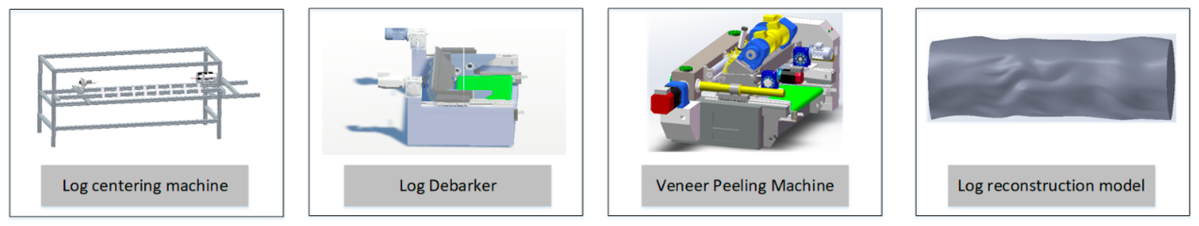
Regarding the core equipment resources involved in the rotary cutting production line of logs, including the log centering machine, log debarker, and veneer peeling machine, modeling tools such as 3Dmax and Solidworks are used to create geometric models based on the actual equipment (Figure 4). The geometric model is imported into Unity3D and physical properties are added, achieving good spatiotemporal consistency with physical entities. At the same time, the virtual entity needs to complete its production behavior through control commands and program driving, which requires the definition of relevant virtual services [16]. Therefore, the behavior criteria of the equipment virtual entity are defined as follows:
In (3), D1 represents the equipment virtual entity and S1 represents the equipment behavior model. The digital space should establish a corresponding twin model for the functional components of actual equipment to achieve synchronized mapping in behavior. V1 represents the driving service, and the organic connection and operation of the behavior model require support from various driving services. In Unity3D, C# programming language and control protocols are used to control them. In addition, the implementation of device functions, signal processing, model behavior, and constraints on operating rules can all be achieved through driving services.
For logs, different geometric forms correspond to different processing stages. Different stages drive the evolution of product geometric states based on their process data. Therefore, the product digital twin model is positioned as follows:
In (4), S2 represents the three-dimensional state model of the product and V2 represents the evolution driving service.
The digital twin model of the rotary cutting system production environment is:
In (5), C represents the environmental rule constraint model, S3 represents the environmental state model, and V3 represents the environmental detection service. The physical layer obtains environmental data through sensors, which is then parsed in the service layer and displayed quantitatively. Combined with data, algorithm models and other technologies are used to study the system, achieving intelligent decision-making and optimization of the digital twin production line operation process.
2.1.4. Digital Twin Data
As a bridge for information transmission, twin data establishes the connection between the physical entity of the log rotary cutting system, the virtual model, and the service system [17]. The fused data, formed by integrating physical data and virtual data, can provide support for cutting optimization, cutting simulation, remote operation and maintenance, and other services. The digital twin data comprises virtual entity data, physical entity data, and service-generated data during system operation, continuously undergoing real-time optimization and updates with changes in the digital twin system’s operational state. It consists of static and dynamic data. Static data includes the device dimensions, material information, and assembly relationships of the physical and virtual entities, representing the physical attributes and original design data. Dynamic data consists of data from the physical entity, including real-time motion data monitored by sensors, as well as simulation data from the virtual entity, such as simulated loads and rule constraints. Additionally, it includes operational data derived from the models of both the physical and virtual entities, such as the analysis data of log characteristics and processing parameters. The data composition is illustrated in Figure 5.
2.1.5. Service System
The service system refers to the functional services that encapsulate various models and algorithms required during the application of digital twins. This layer supports the internal functions of digital twins through tool components, middleware, and module engines in a service-oriented manner. In this paper, we design a service system to address the problem of high heterogeneity in wood. The system integrates the following tasks: interacting with the physical layer to obtain data frames containing sensor data, sensor IDs, and rotation angles; processing the data frames into 3D point cloud data by triangulation based on the sensor IDs; solving the coordinates of the center of the maximum inscribed cylinder by using the least squares method [18], as presented in Algorithm 1; reconstructing the 3D model of the point cloud data using the Delunary3d algorithm [19]; confirming the processing parameters based on the size of the maximum inscribed cylinder through kinematic analysis, including the card shaft motor speed and rotating cutter feed rate; and finally verifying the processing parameters by simulating the cutting process using a 3D Boolean operation [20] on the reconstructed model and outputting the estimated yield.
| Algorithm 1 Finding the largest inscribed cylinder of a log |
| Input: : The abscissa of log point cloud data; : The ordinate of point cloud data; : The number of log point cloud data; Output: : The abscissa of the center of the log’s largest inscribed cylinder; : The ordinate of the center of the log’s largest inscribed cylinder; : The radius of the center of the log’s largest inscribed cylinder; 1: function GetInsCylinerLog 2: for each do 3: 4: define the unknown model as a function 5: end for 6: for each do 7:; ▹ build error function 8: end for 9: for each do 10: 11: solve for the unknown 12: end for 13: return 14: end function |
The processing procedure of the rotary cutting system for logs involves finding the clamping point of the log after it is centered, removing the outer waste using the log debarker, and finally machining it into a veneer with a veneer peeling machine. Therefore, two types of processing equipment are involved. Due to the different processing modes of the log debarker and the veneer peeling machine, kinematic analysis is separately conducted.
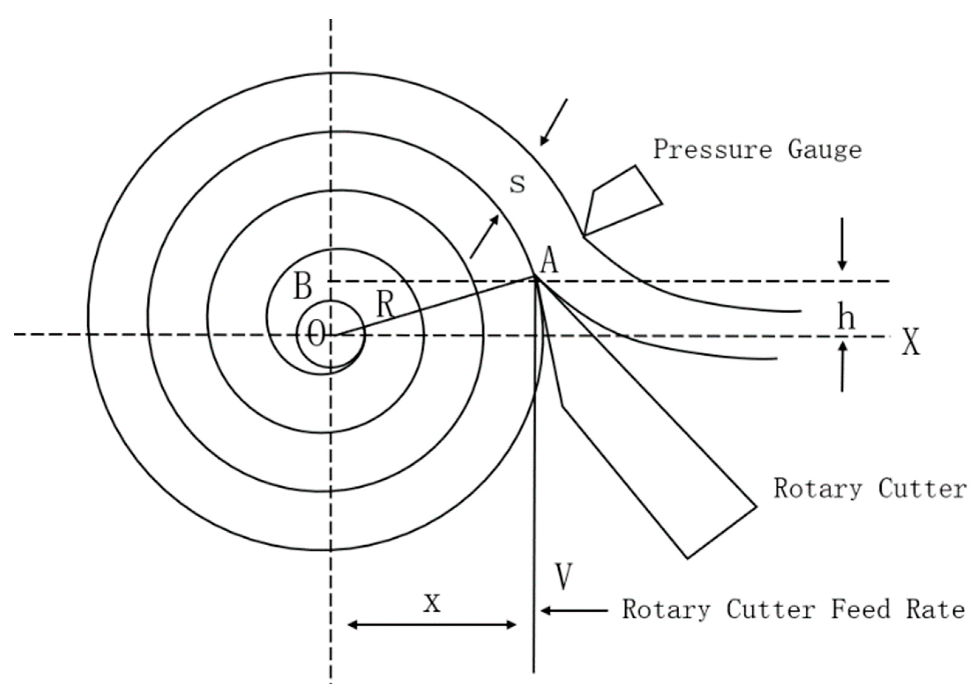
The log debarker machine uses a cardan shaft processing mode, with two cardan shafts clamping the log to maintain a certain speed, and the rotating cutter moves linearly towards the log. In the rotary cutting process, the motion trajectory of a point on the cutting edge of the rotary cutter on the cross-section of the log can be called the rotary cutting curve. A coordinate system is established with the center of the log as the origin. During rotary cutting, the rotary cutter edge moves from point A to point B, with the distance between the rotary cutter blade and the horizontal plane of the cardan shaft axis being h, the veneer thickness being s, the instantaneous radius of the log being R, and the feeding speed of the rotary cutter edge being V (Figure 6).
As the rotary cutter blade moves toward the xo direction, we have:
Assuming the log speed is n, the angular speed of the log is:
Thus, the time, t, can be expressed in terms of the rotation angle of the log:
The parameter x can be represented in terms of R and h using the Pythagorean theorem. Since the rotary cutting curve is an Archimedean spiral, the instantaneous radius of the log can be expressed as:
Where α is the Archimedean spiral’s level distance:
By substituting the above formula into (6) and simplifying, we obtain:
Therefore, when processing with the log debarker, the feeding speed of the rotary cutter is related to the preset veneer thickness and the speed of the cardan shaft. The feeding speed of the rotary cutter can be determined by the preset veneer thickness and the initial motor speed.
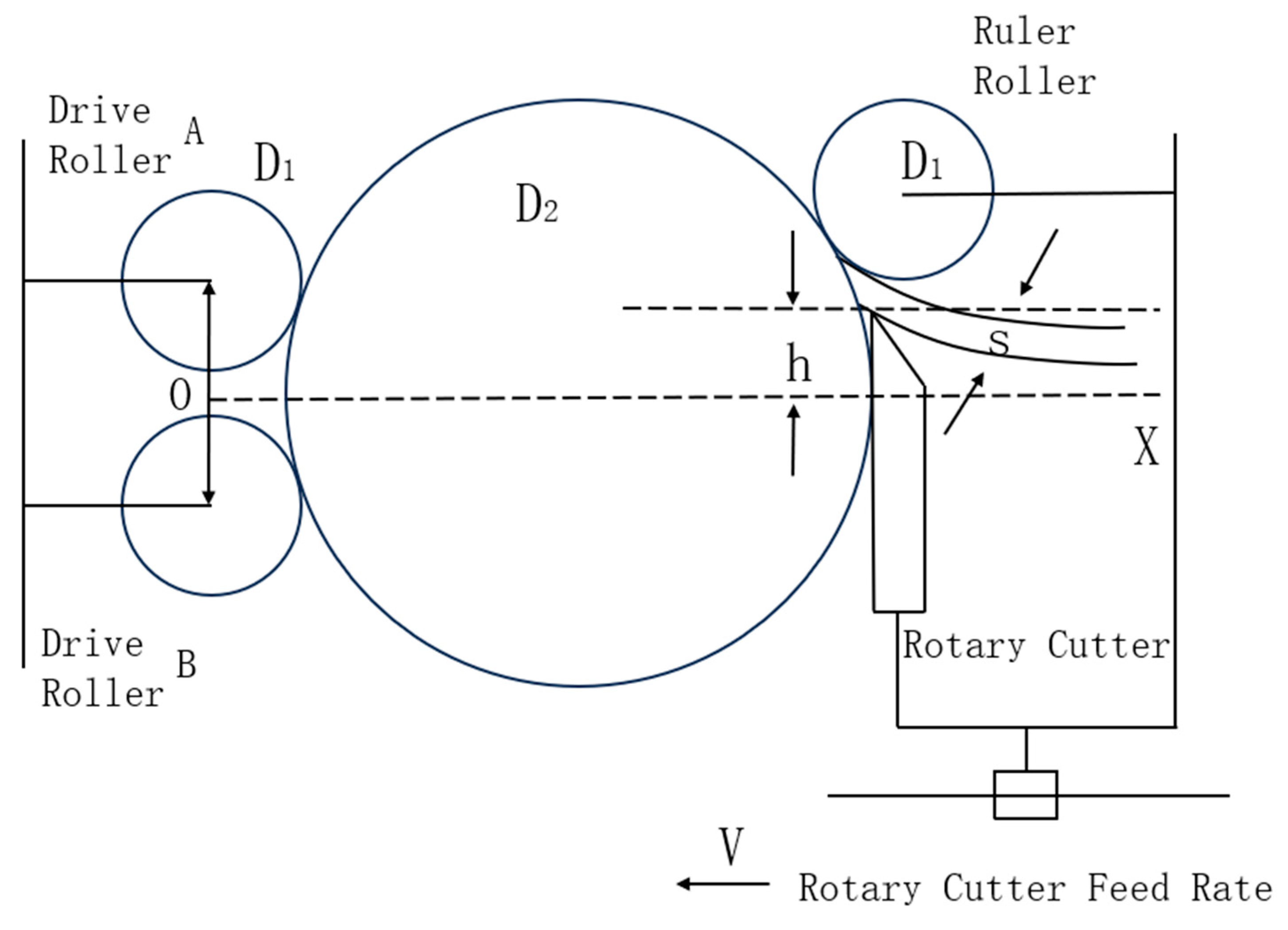
On the other hand, the rotary cutting machine uses a cardan-free processing model. The machine uses a squeezing friction roller (presser roller) that both applies pressure and feeds the log and two main friction rollers (drive rollers) with surface patterns that press against the log and drive it through friction. A rotary blade contacts the log below the presser roller to generate a cutting force and begin the rotary cutting production, as shown in Figure 7.
Establish a coordinate system with the center of the connecting line of the two drive rollers as the origin. Assuming the distance between the two drive rollers is L, the distance between the rotary cutter and the horizontal line is h, the diameter of the three rollers is D1, the instantaneous diameter of the log is D2, the veneer thickness is S, the rotational speed of the drive roller is n, and the rotational speed of the log is N, then the horizontal coordinate of the rotary cutter edge during the log rotary cutting process can be expressed as:
Taking the derivative of both sides with respect to time, t, on both sides, we have:
As the drive roller drives the log to rotate and the rotary cutter to perform rotary cutting, we have:
By definition, the derivative of position with respect to time is velocity; by substituting the above formula into (12) and expanding, we obtain:
Therefore, in the cardan-free processing mode, the feeding speed of the rotary cutter edge is affected by the instantaneous diameter of the log, the rotational speed of the cardan shaft, and other fixed parameters. Therefore, the feeding initial speed of the rotary cutter can be obtained by presetting various parameters, and the feeding speed of the rotary cutter is updated in real-time based on the instantaneous diameter of the log in each frame to achieve closed-loop calculation and control of the feeding speed of the rotary cutter.
In Unity3D, the rotation speed of the log’s virtual entity and the movement mode of the processing equipment’s virtual entity are controlled based on the above kinematic model, and the 3D Boolean operation method is used to perform the rotation cutting simulation.
2.1.6. The Connection of Each Part
The connection is achieved through various interfaces or protocols, enabling the interconnection and communication between the physical entity of the log rotary cutting system, the virtual model of the log rotary cutting system, twin data, and services. It allows real-time updates and iterative interactions among the components, thereby forming a dynamic, closely integrated, and organic whole of the log rotary-cutting digital twin.
3. Results
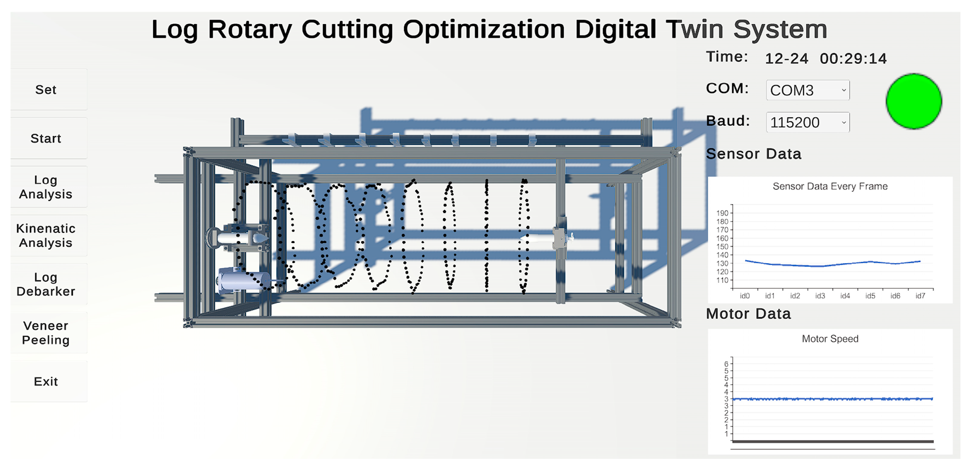
This article uses Unity3D software as a 3D visualization system platform which interacts with physical layer devices in real-time through data interfaces. It uses particle effects to render physical layer point cloud data and dynamically visualize the collection process. The XCharts plugin is used to visualize physical layer data as dynamic charts. The platform is integrated with the digitally twinned visualization system for optimizing log rotary cutting, providing service layer 3D reconstruction and rotary cutting simulation functions.
The main interface of the visualization platform has multiple functions, including data collection, centering and cutting analysis, and rotary cutting simulation, all of which are driven by UI buttons. The data collection module controls the log-centering machine to collect data and displays the 3D point cloud effect in real-time on the platform. The right side of the interface shows the working status information of the log-centering machine, including the communication status, sensor data, and motor speed, as shown in Figure 8.
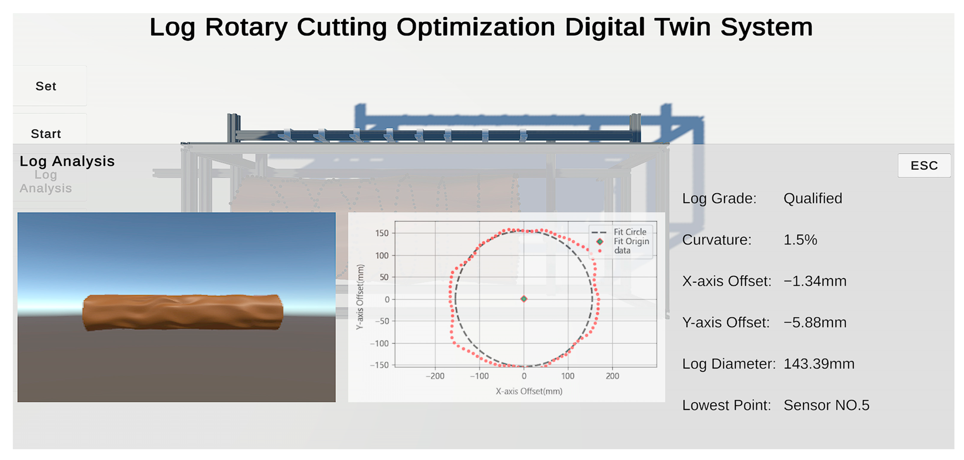
The log centering analysis module focuses on reconstructing the three-dimensional point cloud information of the log and solving for the maximum inscribed cylinder. The information panel on the right side of the interface displays the detected log feature information, including the log grading based on curvature, the centroid offset, and the lowest point position of the log. If the log is deemed unacceptable based on the grading, it can be sawed at the lowest point position. The log curvature is calculated by dividing the arch height by the length, as per the national standard, as shown in Figure 9.
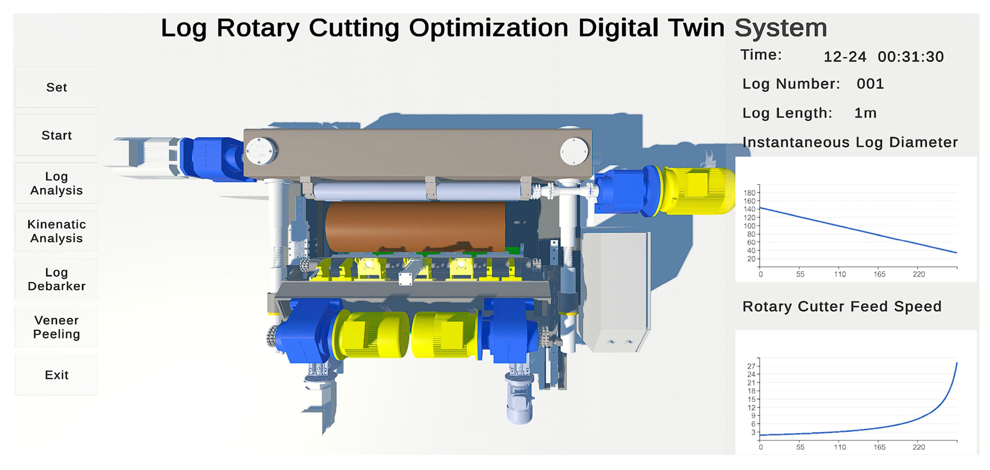
The rotary cutting analysis module is used to confirm the machining parameters, including the motor speed and the feed rate of the rotary blade, based on a kinematic model established using the innermost circumscribed cylinder of the log and the preset thickness of the veneer. The module employs the three-dimensional model of the log and the preset equipment model to simulate and verify the machining parameters obtained in the simulation module, as shown in Figure 10.
4. Discussion
In this study, the point cloud information of logs with radii of 150 mm, 175 mm, and 200 mm was collected using the physical layer experimental platform. The system was validated and calibrated using standard log data. Taking the example of a standard log with a radius of 150 mm, the point cloud data was processed using the centering analysis module in the service system to solve for the maximum inscribed cylinder. The resulting fitting error for the dimensions was 0.12 mm, and the calculated error for the centroid position was 0.03 mm and −0.07 mm. Considering the negligible error in practical experiments, the system meets the requirements for standard logs.
To verify the accuracy, 50 sets of experimental data were collected from logs with radii of 150 mm, 175 mm, and 200 mm, respectively, after modeling and fitting with the least squares method, shown in Table 1.
By following the same procedure and collecting data with different starting angles for irregularly shaped logs, we obtained point cloud data for irregularly shaped logs. The point cloud data was then triangulated to reconstruct the surface mesh. It can be observed that the surface of the model exhibits distinct depressions and protrusions, and the trend of surface undulation is highly similar to the Solidworks model, indicating a high degree of resemblance. The point cloud information and surface reconstruction results for irregularly shaped logs are shown in Figure 9.
The point cloud data can be analyzed, and a maximum inscribed cylinder can be solved through the centroid analysis module in the service system. The effect is shown in Figure 9.
According to industry conventions, manual measurements of the centroid are conducted using selected cross-sections of irregular-shaped logs. From Table 2, it can be observed that when comparing the measurements with the Solidworks model as the reference, the system’s volume calculation error decreased from 12.8% in manual measurements to 2.7%, and the yield calculation error decreased from 23.5% in manual measurements to 5.7%.
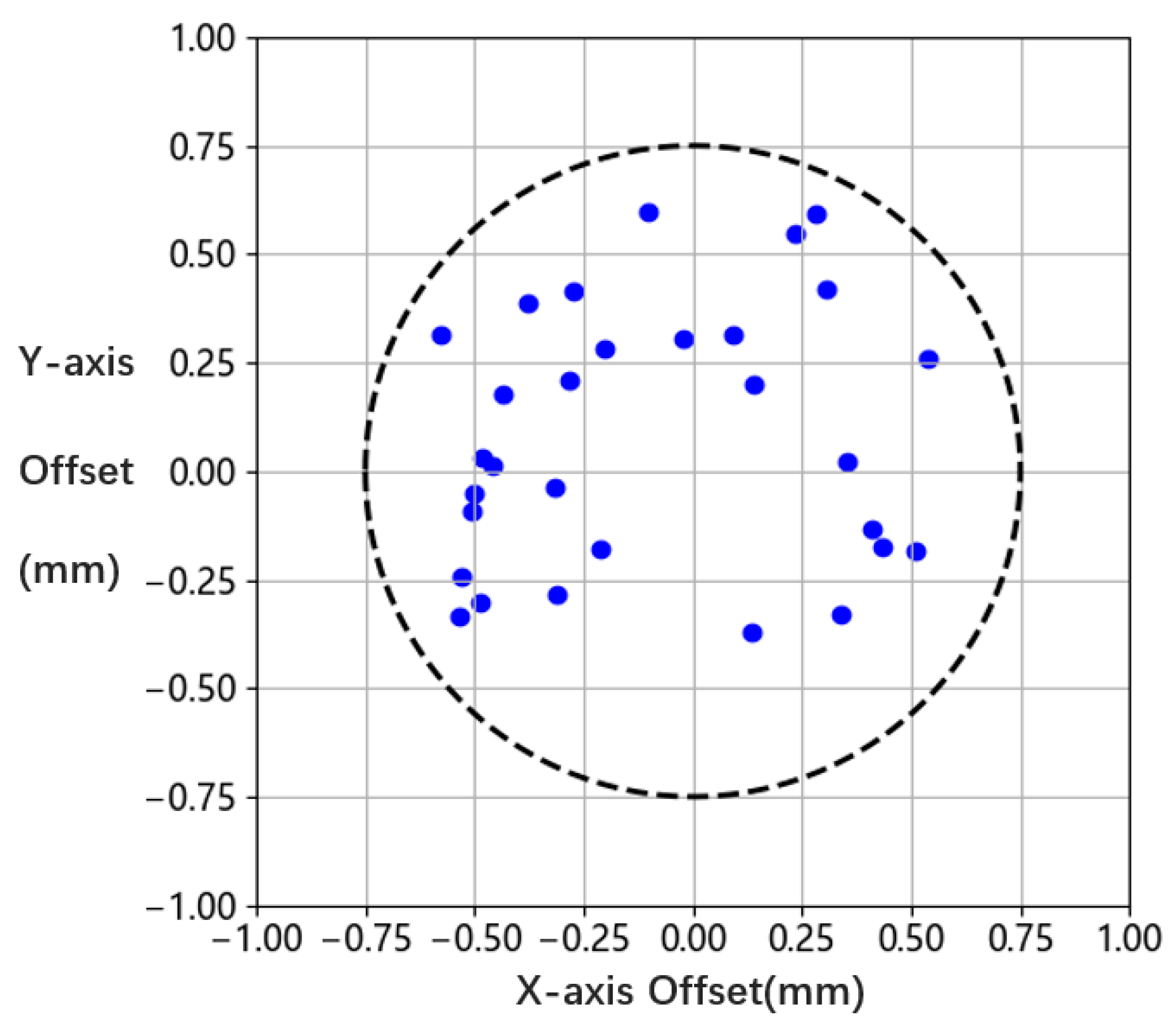
To validate the stability of the equipment, a repeatability experiment was conducted on the collection of irregular-shaped logs for 30 repetitions. After data processing and reconstruction, the fitted centroid data exhibited an error distribution within a circle centered at (0, 0) with a radius of 0.75 mm, as shown in Figure 11. This result demonstrates the stability of the collection equipment and algorithm.
5. Conclusions
This paper addresses the issues of low intelligence levels and poor log utilization in log peeling equipment. To overcome these challenges, a digital twin-based optimization system for log peeling is proposed and constructed. An optimization method for log peeling is introduced and experimentally validated. The system enables the autonomous capture of point cloud information from logs, analysis of peeling strategies, and simulation-based research on processing parameters. This enhances the digitization level of log-centering equipment and provides scientific guidance for subsequent log-peeling processes, thereby maximizing the utilization of timber resources and improving the intelligence level of log-peeling equipment. Furthermore, the developed system serves not only as a testing platform for various local optimization algorithms in log-peeling production lines but also addresses the high development and testing costs associated with individual equipment. Additionally, the system utilizes the extensive data collected during the log peeling process to analyze equipment allocation and scheduling issues in the production line. In conclusion, this system enables more rational, efficient, and environmentally friendly production planning, thereby promoting quality improvements, cost reductions, and efficiency enhancements in enterprises. It facilitates the transformation and upgrading of enterprises towards digitization, intelligence, and greening, contributing to the achievement of carbon neutrality goals in our country.
Author Contributions
L.Y. and J.W. were the advisors. Y.Z. designed the scheme. Y.Z. and X.S. carried out the implementation. Y.Z. wrote the manuscript. L.Y., J.W. and Y.Z. revised the final version of the text. All authors have read and agreed to the published version of the manuscript.
Funding
This work was supported by National Forestry and Grassland Administration: GLM [2021] and Beijing Forestry University Excellent Experimenter Item: BJFUSY20220707.
Data Availability Statement
The data presented in this study are available on request from the corresponding author. The data are not publicly available due to the project not being concluded yet.
Acknowledgments
The authors would like to thank the School of Technology Beijing Forestry University for support.
Conflicts of Interest
The authors declare no conflict of interest.
References
- Zhang, X.; Zhang, Q.; Li, G.; Hu, J. Exploring the application of digital twin in the field of micro turbine engine core components. Energy Sci. Eng. 2023, 11, 2929–2943. [Google Scholar] [CrossRef]
- Grieves, M.; Vickers, J. Digital Twin: Mitigating Unpredictable, Undesirable Emergent Behavior in Complex Systems. In Transdisciplinary Perspectives on Complex Systems; Kahlen, J., Flumerfelt, S., Alves, A., Eds.; Springer: Cham, Switzerland, 2017. [Google Scholar] [CrossRef]
- Shohin, A.; Xu, X.; Ray, Y.; Lu, Y. Digital Twin as a Service (DTaaS) in Industry 4.0: An Architecture Reference Model. Adv. Eng. Inform. 2021, 47, 101225. [Google Scholar] [CrossRef]
- Lu, Q.; Yang, R.; Zhong, M.; Wang, Y. An Improved Fault Diagnosis Method of Rotating MachineryUsing Sensitive Features and RLS-BP Neural Network. IEEE Trans. Instrum. Meas. 2020, 69, 1585–1593. [Google Scholar] [CrossRef]
- Panwar, N.G.; Singh, S.; Garg, A.; Gupta, A.K.; Gao, L. Recent Advancements in Battery Management System for Li-Ion Batteries of Electric Vehicles: Future Role of Digital Twin, Cyber-Physical Systems, Battery Swapping Technology, and Nondestructive Testing. Energy Technol. 2021, 9, 2000984. [Google Scholar] [CrossRef]
- Voigt, I.; Inojosa, H.; Dillenseger, A.; Haase, R.; Akgün, K.; Ziemssen, T. Digital Twins for Multiple Sclerosis. Front. Immunol. 2021, 12, 669811. [Google Scholar] [CrossRef] [PubMed]
- Shahat, E.; Hyun, C.T.; Yeom, C. City Digital Twin Potentials: A Review and Research Agenda. Sustainability 2021, 13, 3386. [Google Scholar] [CrossRef]
- Coupry, C.; Noblecourt, S.; Richard, P.; Baudry, D.; Bigaud, D. BIM-Based Digital Twin and XR Devices to Improve Maintenance Procedures in Smart Buildings: A Literature Review. Appl. Sci. 2021, 11, 6810. [Google Scholar] [CrossRef]
- Wery, J.; Gaudreault, J.; Thomas, A.; Marier, P. Simulation-optimisation based framework for Sales and Operations Planning taking into account new products opportunities in a co-production context. Comput. Ind. 2018, 94, 41–51. [Google Scholar] [CrossRef]
- Morin, M.; Gaudreault, J.; Brotherton, E.; Paradis, F.; Rolland, A.; Wery, J.; Laviolette, F. Machine learning-based models of sawmills for better wood allocation planning. Int. J. Prod. Econ. 2020, 222, 107508. [Google Scholar] [CrossRef]
- Chen, Z.; He, Z.; Chao, B.; Guo, H. Visual Detection Application of Lightweight Convolution and Deep Residual Networks in Wood Production. Wirel. Commun. Mob. Comput. 2022, 2022, 9465433. [Google Scholar] [CrossRef]
- Chabanet, S.; Bril El-Haouzi, H.; Morin, M.; Gaudreault, J.; Thomas, P. Toward digital twins for sawmill production planning and control: Benefits, opportunities, and challenges. Int. J. Prod. Res. 2023, 61, 2190–2213. [Google Scholar] [CrossRef]
- Wang, G.; Bing, Z.; Hou, Z.; Guan, Y.; Qi, X.; Liu, M. Workshop Management and Control System Based on Digital Twin. In Proceedings of the 2022 8th International Conference on Control, Automation and Robotics (ICCAR), Xiamen, China, 8–10 April 2022; Volume 2022, pp. 16–21. [Google Scholar] [CrossRef]
- Tao, F.; Zhang, M. Digital Twin Shop-Floor: A New Shop-Floor Paradigm Towards Smart Manufacturing. IEEE Access 2017, 5, 20418–20427. [Google Scholar] [CrossRef]
- Zhuang, C.; Liu, J.; Xiong, H. Digital twin-based smart production management and control framework for the complex product assembly shop-floor. Int. J. Adv. Manuf. Technol. 2018, 96, 1149–1163. [Google Scholar] [CrossRef]
- Wang, Y.; Martinsen, K.; Yu, T.; Kesheng, W. Advanced Manufacturing and Automation X; Springer: Singapore, 2021. [Google Scholar]
- Deng, Y.; Xing, C.; Cai, L. Building Image Feature Extraction Using Data Mining Technology. Comput. Intell. Neurosci. 2022, 2022, 8006437. [Google Scholar] [CrossRef]
- Bruno, L.; Sylvain, P.; Nicolas, R.; Jérome, M. Least squares conformal maps for automatic texture atlas generation. ACM Trans. Graph. 2002, 21, 362–371. [Google Scholar] [CrossRef]
- Weatherill, N.P.; Hassan, O. Efficient three-dimensional Delaunay triangulation with automatic point creation and imposed boundary constraints. Int. J. Numer. Methods Eng. 1994, 37, 2005–2039. [Google Scholar] [CrossRef]
- Falkowski, B.J.; Schafer, I.; Chang, C.-H. Effective computer algorithm for thecalculation of disjoint cube representation of Boolean functions. Midwest Symp. Oncircuits Syst. 1993, 2, 1308–1311. [Google Scholar]
Figure 1.
The five-dimensional model of the digital twin system for optimizing log peeling.

Figure 2.
Experimental materials for CNC lathe machining.

Figure 3.
(a) Composition of the experimental platform; (b) The experimental platform. (1: front card shaft; 2: synchronous belt pulley; 3: DC motor; 4: rear card shaft; 5: sensor).
Figure 3.
(a) Composition of the experimental platform; (b) The experimental platform. (1: front card shaft; 2: synchronous belt pulley; 3: DC motor; 4: rear card shaft; 5: sensor).

Figure 4.
Virtual entity of the log rotary cutting system.

Figure 5.
Data composition of the digital twin system for optimizing log rotary cutting.

Figure 6.
Rotary cutting curve.

Figure 7.
Cardless processing principle.

Figure 8.
Data collection interface.

Figure 9.
Log centering analysis interface.

Figure 10.
Log rotary cutting simulation interface.

Figure 11.
Distribution of experimental results.


Table 1.
Standard log centering results.
| Log Size | 150 mm | 175 mm | 200 mm |
|---|---|---|---|
| X-axis offset range (mm) | −0.39~0.63 | −0.23~0.95 | −0.21~0.88 |
| Y-axis offset range (mm) | −0.05~0.82 | −0.31~0.78 | −0.11~0.50 |
| Radius minimum (mm) | 148.73 | 172.55 | 198.36 |
| Radius maximum (mm) | 151.52 | 177.34 | 201.68 |
Table 2.
Comparison of experimental results.
| Data Sources | Solidworks Model | System Measurement Results | Manual Measurement Results |
|---|---|---|---|
| Volume | 0.0842 m3 | 0.0865 m3 | 0.0950 m3 |
| Volume error | - | 2.7% | 12.8% |
| Maximum inscribed circle radius | 150 mm | 154.23 mm | 166.27 mm |
| Yield error | - | 5.7% | 23.5% |
Disclaimer/Publisher’s Note: The statements, opinions and data contained in all publications are solely those of the individual author(s) and contributor(s) and not of MDPI and/or the editor(s). MDPI and/or the editor(s) disclaim responsibility for any injury to people or property resulting from any ideas, methods, instructions or products referred to in the content. |
© 2023 by the authors. Licensee MDPI, Basel, Switzerland. This article is an open access article distributed under the terms and conditions of the Creative Commons Attribution (CC BY) license (https://creativecommons.org/licenses/by/4.0/).
Share and Cite
MDPI and ACS Style
Zhao, Y.; Yan, L.; Wu, J.; Song, X. Design and Implementation of a Digital Twin System for Log Rotary Cutting Optimization. Future Internet 2024, 16, 7. https://doi.org/10.3390/fi16010007
AMA Style
Zhao Y, Yan L, Wu J, Song X. Design and Implementation of a Digital Twin System for Log Rotary Cutting Optimization. Future Internet. 2024; 16(1):7. https://doi.org/10.3390/fi16010007
Chicago/Turabian StyleZhao, Yadi, Lei Yan, Jian Wu, and Ximing Song. 2024. "Design and Implementation of a Digital Twin System for Log Rotary Cutting Optimization" Future Internet 16, no. 1: 7. https://doi.org/10.3390/fi16010007
Note that from the first issue of 2016, this journal uses article numbers instead of page numbers. See further details here.