
Two-Layer Reversible Data Hiding for VQ-Compressed Images Based on De-Clustering and Indicator-Free Search-Order Coding


1
Department of Information Engineering and Computer Science, Feng Chia University, Taichung 40724, Taiwan
2
Department of Electronic Engineering, National Quemoy University, Kinmen 89250, Taiwan
*
Author to whom correspondence should be addressed.
Future Internet 2021, 13(8), 215; https://doi.org/10.3390/fi13080215
Submission received: 2 August 2021
/
Revised: 18 August 2021
/
Accepted: 18 August 2021
/
Published: 20 August 2021
(This article belongs to the Section Cybersecurity)
Abstract
:During transmission of digital images, secret messages can be embedded using data hiding techniques. Such techniques can transfer private secrets without drawing the attention of eavesdroppers. To reduce the amount of transmitted data, image compression methods are widely applied. Hiding secret data in compressed images is a hot issue recently. In this paper, we apply the de-clustering concept and the indicator-free search-order coding (IFSOC) technique to hide information into vector quantization (VQ) compressed images. Experimental results show that the proposed two-layer reversible data hiding scheme for IFSOC-encoded VQ index table can hide a large amount of secret data among state-of-the-art methods with a relatively lower bit rate and high security.
1. Introduction
In the era of fifth generation (5G) mobile networks, information security draws much more attention than ever and various data hiding schemes and secure communication techniques have been proposed [1,2,3,4]. The data hiding technique embeds secret messages into a carrier, such as an audio, a video, or a digital image. Upon receiving the marked carrier, the receiver extracts the secret data and recovers the carrier. Among the existing data hiding methods, not all of them can losslessly recover the carrier. A method that can perfectly recover a carrier is classified as a reversible data hiding (RDH) method [5,6,7,8]; otherwise, it is irreversible [9,10,11,12].
The most popular carrier is digital images. Since there are various compression formats for digital images, including lossy compression [13,14,15] and lossless compression [16,17], an efficient data hiding techniques should be designed according to the features of the target format. In this research, we focus on the data embedding of VQ compressed images.
Before VQ compression, a codebook should be established first. The LBG (Lindo-Buzo-Gray) algorithm [18] is a commonly applied technique to train a codebook. The compression process starts with partitioning the given image into disjoint blocks. Then, each block is encoded by finding its best fitting codeword in the codebook and represent the block with the index of the found codeword. As a result, the given image is encoded into an index table, which is also called the VQ compressed code.
Some methods have been proposed to further compress the VQ code [16,19]. In 1992, Kim proposed side-match vector quantization (SMVQ) [19]. Only the first row and the first column of the index table are recorded. In the decompression phase, blocks of the first row and the first column are decompressed first. Then, the remaining image blocks are predicted by side-matching with the codewords in the codebook. The compress ratio is very high. However, the quality of the decompressed image is poor.
In 2004, Chang et al. proposed a reversible scheme [20] to embed secret data in SOC-encoded VQ indices. The indicator bit of each SOC-encoded index is directly replaced by a secret bit. When a flip of indicator bit is encountered, its following format of index code should be exchanged correspondingly. The embedding rate is satisfactory; however, exchange of index format severely expands the code length.
After that, improved versions [21,22,23] were proposed. In the original version of SOC data hiding, to switch an uncompressible code into a camouflaged compressed code, a reserved code is applied followed by the original index. Which makes a great expansion of file size and reduces the ability of SOC compression. In 2011, Rahmani et al. proposed an improved version [21], which leaves the uncompressible index unembedded and thus releases the reserved code. In 2016, Qin and Hu proposed a data hiding scheme [23] based on the improved search-order coded (ISOC) VQ indices. The compression ability and the embedding capacity can be further improved. These studies make different trade-offs between embedding rate and file expansion based on the same scheme of indicator bit replacement. In recent years, RDH for VQ index table based on different kinds of compression methods for VQ have been proposed [24,25,26,27].
Another series of RDH for VQ index table is to apply the de-clustering concept, which is proposed by Chang et al. at 2006 [28]. With the help of SMVQ, indices of VQ can switch between a dissimilar pair to embed a secret bit without expanding the code length. Later, different kinds of clustering techniques [29,30] have been proposed to improve the hiding capacity of the de-clustering approach.
In this paper, we incorporate the de-clustering technique with an SOC-based method to improve data hiding capacity and information security. A two-layer RDH scheme for VQ index table is proposed. The de-clustering concept is applied to embed the first layer of secret data. Then, an indicator-free SOC is applied to compress the de-clustered index table. During compression, the second layer of secret data is embedded to camouflage a regular VQ index table. Experimental results demonstrate that the proposed scheme can hide a satisfactory amount of secret data with high security as expected.
The rest of this paper is organized as follows. VQ compression and SOC encoding techniques are introduced in Section 2. The proposed two-layer RDH scheme is presented in Section 3. Experimental results and comparisons with related works are provided in Section 4. Finally, conclusions are made in Section 5.
2. Related Work
The subject of our embedding scheme is SOC-encoded VQ index table. To know its features, we first introduce the VQ image compression and its corresponding SOC method.
2.1. VQ Image Compression
Vector quantization (VQ) is a simple and efficient image compression technique. It has a high compression ratio with an adjustable bit rate and fidelity. Therefore, it is very commonly applied in real applications.
Before compression, a codebook should be established. Firstly, three to five typical images are selected. Ideally, both smooth and complex images are included. Then, each image is divided into mutually exclusive blocks of size . Each of the blocks is treated as a one-dimensional vector with tuples. According to the desired codebook size n, 256 for example, the overall blocks are clustered into n groups. Finally, the mean vector of each vector group is recorded as a codeword. The collection of n codewords forms a codebook.
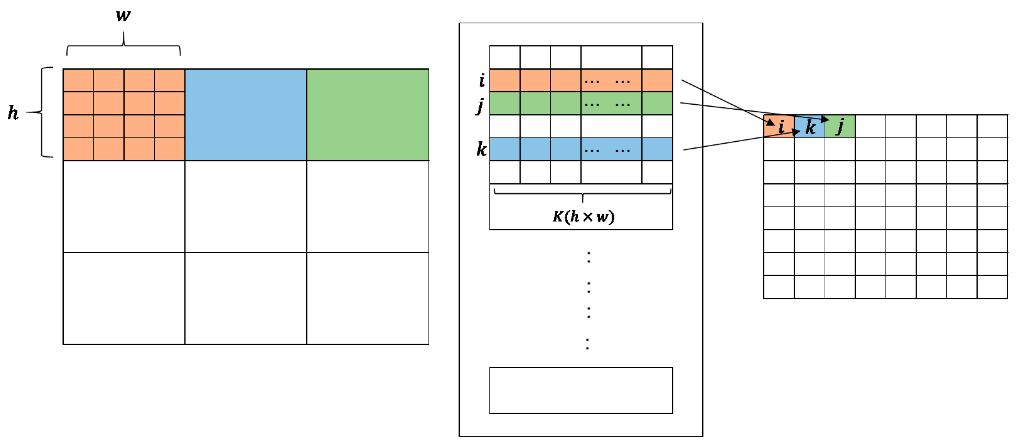
The compression process is illustrated in Figure 1. The image to be compressed is divided into blocks of size in the same way as the codebook training process. Then, each block is rearranged into a vector and compared with the codewords in the codebook. The serial number of the closest codeword is recorded into the index table. As a result, the given image is compressed into an index table.
A typical setting of parameters is to compress image blocks sized with a codebook of length 256. Under such circumstance, the compression ratio is 16:1. To get a better fidelity of approximation, codebooks with length 512 or 1024 are also applicable. Of course, the compression ratio is reduced at the same time.
2.2. Search-Order Coding (SOC)
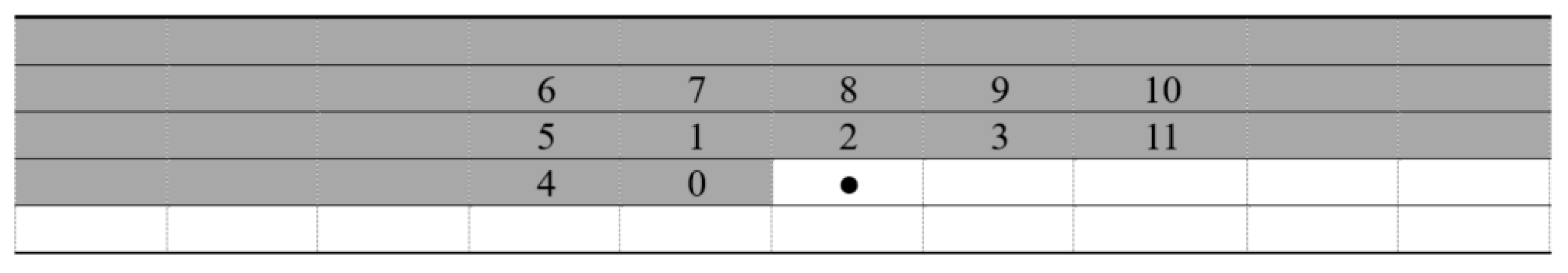
In 1996, [17] utilized the high similarity between index values within a local region to further compress the VQ index table. The process is illustrated in Figure 2. Assuming that the black-dotted element is the current pixel under processing. Since the indices are recorded in the raster scan order, the indices in the gray area are available to be referred. The order of searching is as labeled in Figure 3. When a matched index is found within a predefined search range, the current index is encoded with the serial number of the matched index. The serial number of indices is assigned along the searching path with repeated index values skipped to improve the coding capacity.
To distinguish between SOC representable and non-representable indices, an additional indicator bit is prefixed to an SOC serial number or an original index. The existing RDH schemes for SOC-encoded VQ indices focus on replacing the indicator bit with a secret bit and modifying its following code to fit the data type indicated. In cases where the indicator bit mismatches with the secret bit, the succeeding code may be significantly lengthened.
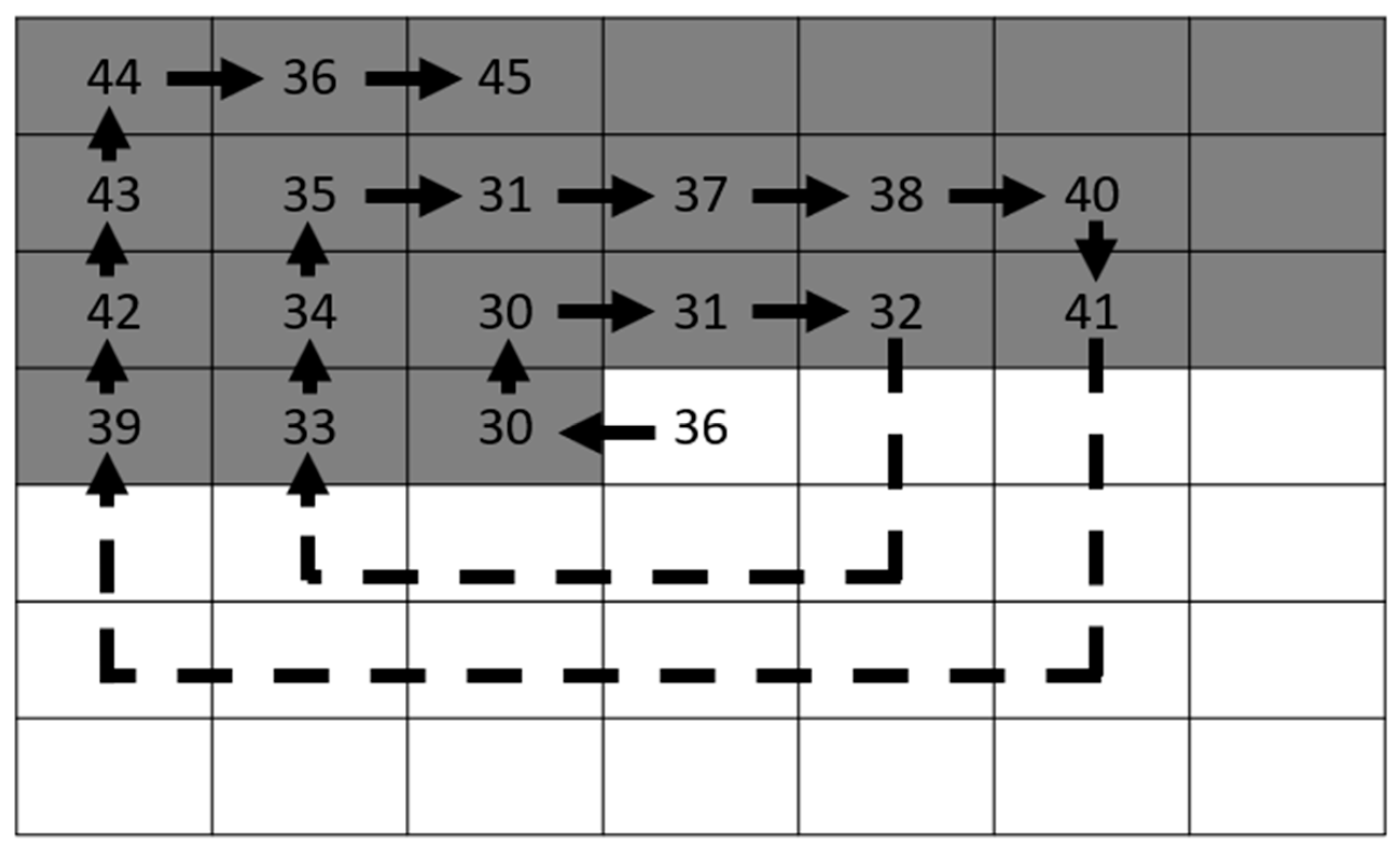
An example of SOC is illustrated in Figure 3, where the index 36 at the center is under processing and the gray portion is the referable indices that have been compressed earlier. Suppose we apply four bits to represent the serial number of indices along the search path and an indicator bit valued 1 to indicate a compressible index. The first encountered index 30 is labeled as 0000. The next index is also 30. According to the rule of labeling, repeated indices are left unlabeled. Then, the process is proceeded step by step and labels the indices 31, 32, 33, 34, 35, (31), 37, 38, 40, 41, 39, 42, 43, 44, and 36 as 0001 to 1110. The parenthesized 31 is also a repetition index and therefore skipped. As a result, the current index 36 is compressed into five bits 11,110, where the first bit 1 is the indicator bit.
3. Proposed Scheme
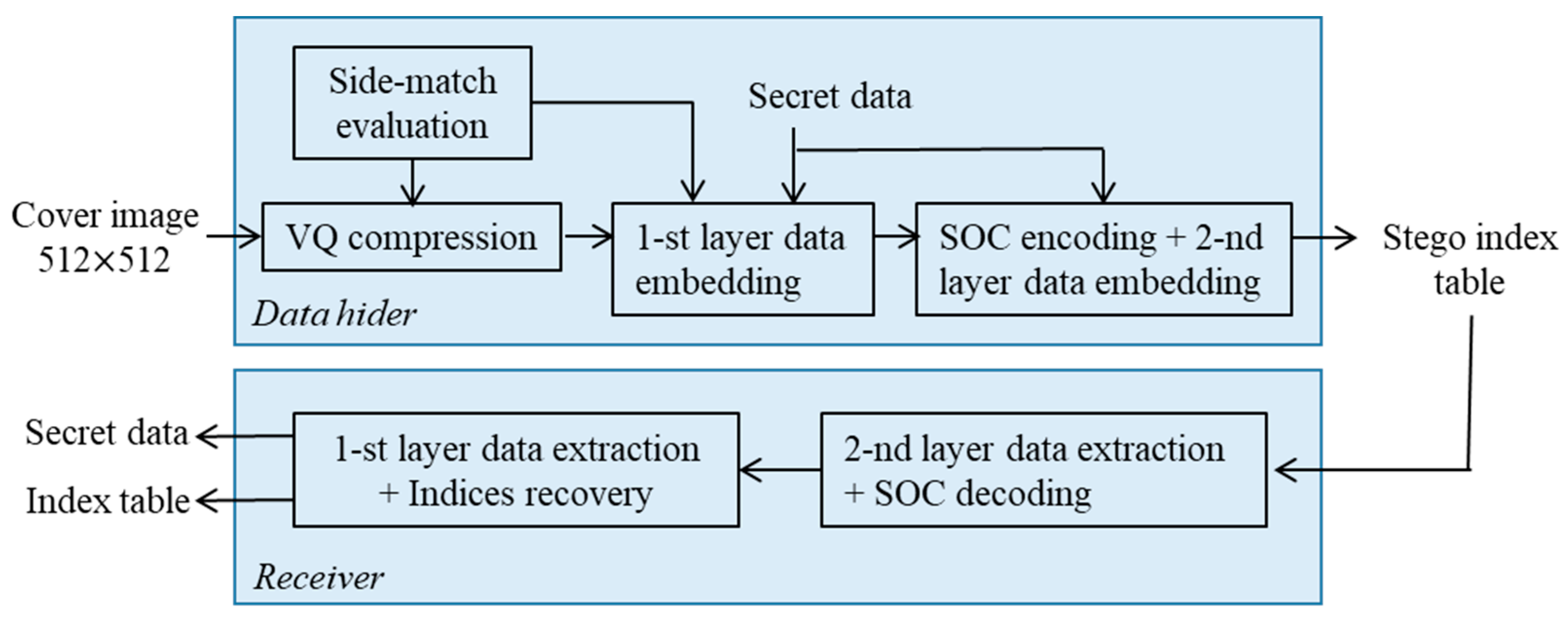
The proposed data hiding scheme for VQ index table is based on the concept of de-clustering and the indicator-free SOC. The proposed RDH scheme includes two layers. In the first layer of data embedding, the de-clustering concept is leveraged with the help of side-match evaluation. The second layer of data embedding is executed during an indicator-free SOC compression of the VQ indices. By appending secret bits to a SOC compressed VQ index to camouflage a regular VQ index. The complete flowchart is shown in Figure 4, where the processing procedures for data hider and receiver are both illustrated. In the following subsections, the side-match evaluation, the first layer of data embedding, the indicator-free SOC compression with the second layer of data embedding, the data extraction, and the index table recovery are described in detail.
3.1. The Side-Match Evaluation
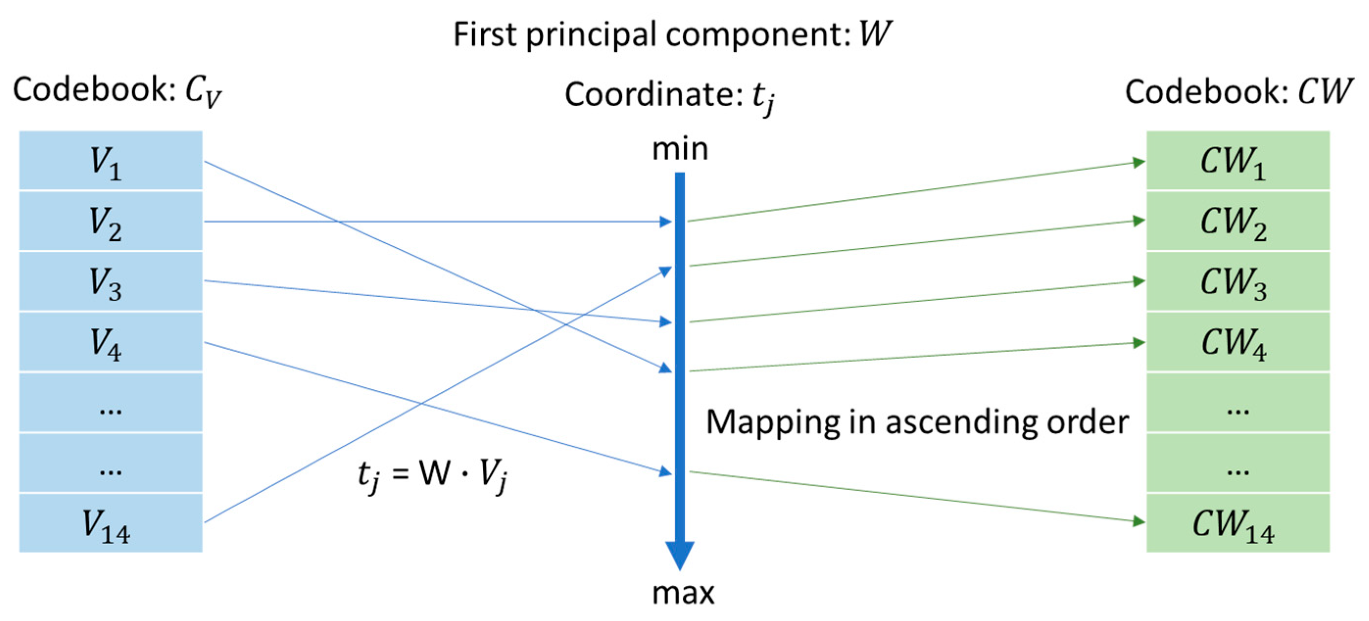
For convenience, we apply a small codebook of length 16 in all illustrative examples, although typical lengths are 256, 512, or 1024 in most real applications. In addition, the head and rear codewords, i.e., CW0 and CW15, are reserved as explained. The reserved codewords are determined after codebook training. After obtaining the codebook, the principal component analysis (PCA) is used to determine the projection values of the fourteen codewords along the first component as shown in Figure 5. The codebook is denoted by , where represents a codeword of 16 pixel-values in the codebook of size 14. The first principal component W of the codewords in the codebook is defined by
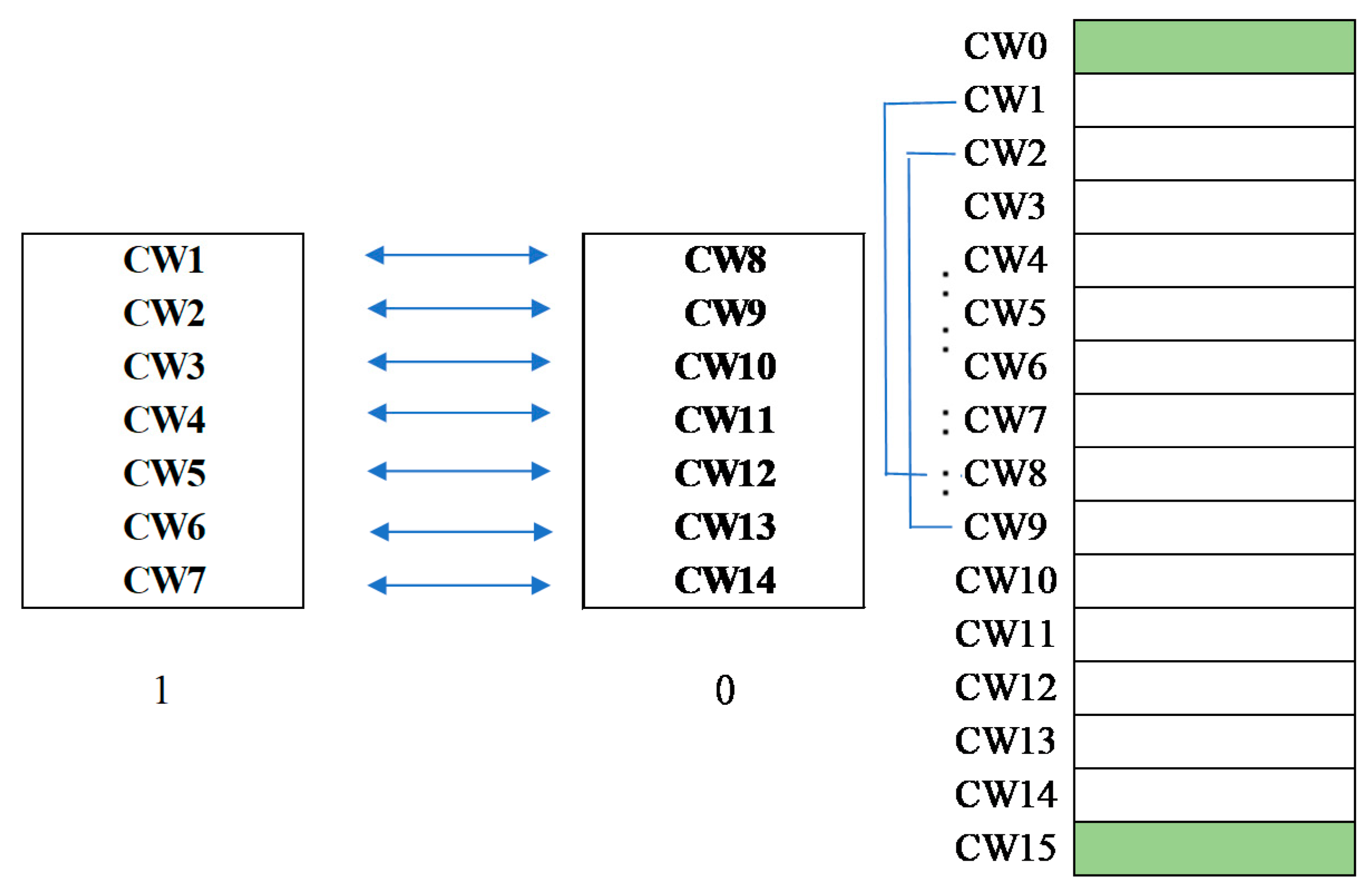
The projections of codewords to this component constitute a data set with maximum variance. Then, the codewords are sorted according to the ascending order of projection value. If the codebook shown in Figure 6 is a PCA-sorted one, we further divide the codewords into two clusters. The upper half is cluster 1, while the lower half is cluster 0. Besides, a one-to-one mapping in their corresponding order within the clusters is defined as illustrated in the figure.
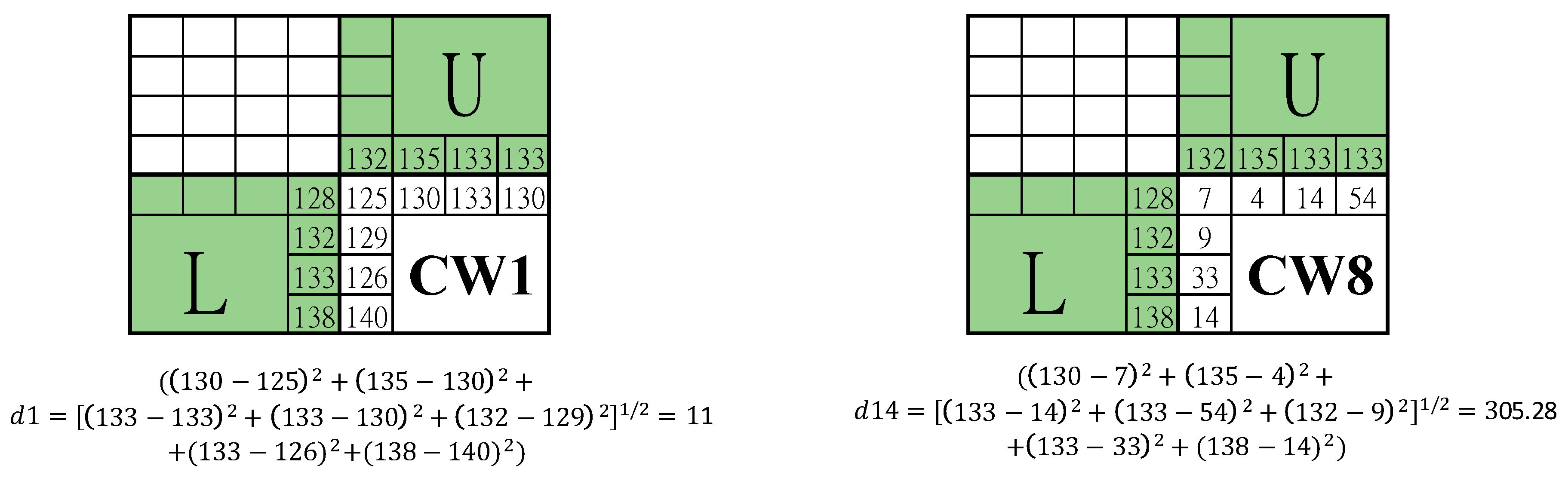
Next, the side-match evaluation is defined as illustrated in Figure 7. For a block in the VQ image, for example ‘CW1’, the pixel values along the border with upper and left blocks are collected to form two vectors, one is constituted by inside pixels and the other is constituted by the outside pixels. For the illustrated case, and . Compute the distance between the two vectors by . The corner pixel is compared with the average value of its top and left neighbors. By replacing the codeword with its counterpart ‘CW8’ according to the one-to-one mapping, another distance can be obtained. Normally, is much smaller than , since the neighboring image blocks are usually like each other. Based on this property, a switching between counterparts can be easily detected and therefore can be exploited to embed secret data.
3.2. The First Layer of Data Embedding Process
The first layer of data embedding in the proposed scheme is based on the side-match evaluation. Since the mapping codeword pair defined between two clusters are dissimilar enough, de-clustering by switching between a mapping codeword pair leads to an abnormal side-match value. The embedding rules are quite simple. The cluster labels ‘1’ and ‘0’ are exploited to indicate the embedded binary bit. When the label of current processing index is matched with the binary bit to be embedded, it is kept unchanged; when they are not matched, the index is switched to its counter codeword according to the predefined mapping. In this way, the secret data can be embedded without lengthening the index code. To execute the side-match evaluation, the indices in the first row and the first column of the index table are treated as the seed indices and kept unchanged. The first layer of data embedding is applied to the residual indices.
Note that the formal (real) VQ image blocks are not always ‘normal’ under side-match evaluation. In such abnormal circumstance, the reserved codewords, i.e., the head and rear codewords, take over. When ‘0’ is to be embedded, the head codeword is inserted; when ‘1’ is to be embedded, the rear codeword is inserted. The insertion of a reserved codeword indicates two things: (1) the secret bit is as it represents for, and (2) the current image block is abnormal, and its index is pushed behind. Knowing the information of an abnormal situation, the actual index of the current image block still can be embedded with a secret bit according to the same rule. Thus, an abnormal image block leads to a double code length; however the embedded data is also doubled. In addition, the binary secret data is stream encrypted before embedding. The algorithm for the proposed secret data embedding scheme is summarized as Algorithm 1.
| Algorithm 1 The first-layer of data embedding for VQ index table. |
| Input: cover image , specialized codebook , codeword mapping function , secret data . Output: 1-st stego index table . 1: Divide the cover image into mutually exclusive blocks sized . 2: Compress the cover image into index table according to codebook . 3: Encrypt the secret data by a stream cipher. 4: For each residual index , 5: Find the cluster label 6: If , 7: Retrieve a secret bit from . 8: If , record to ; else, record to . End 9: Else 10: Retrieve a secret bit from . 11: If , record to ; else record to . End 12: Retrieve a secret bit from . 13: If , record to ; else, record to . End 14: End 15: End |
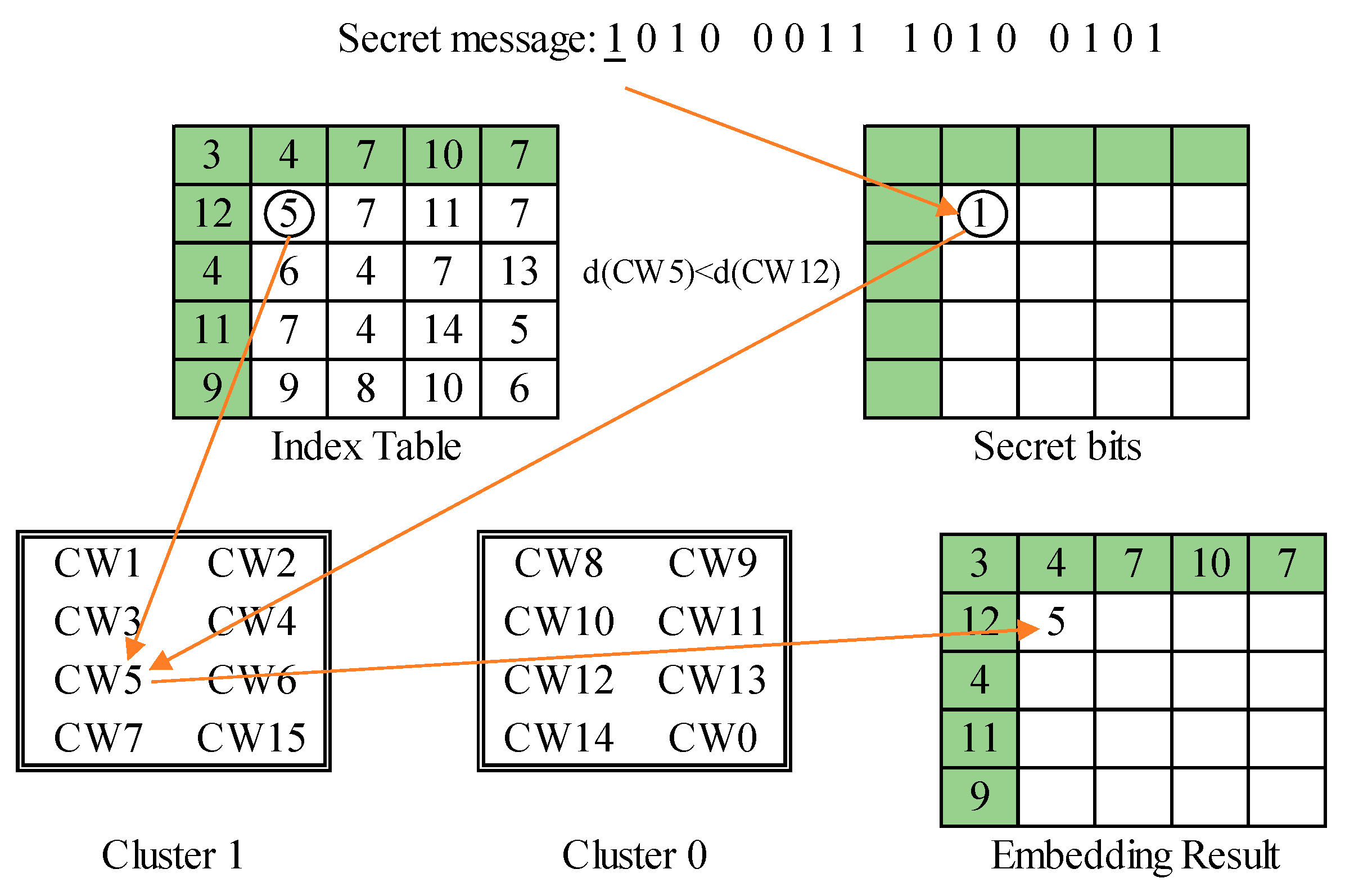
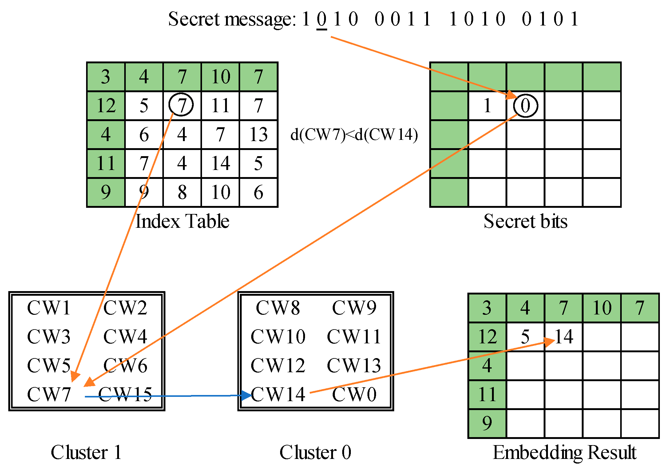
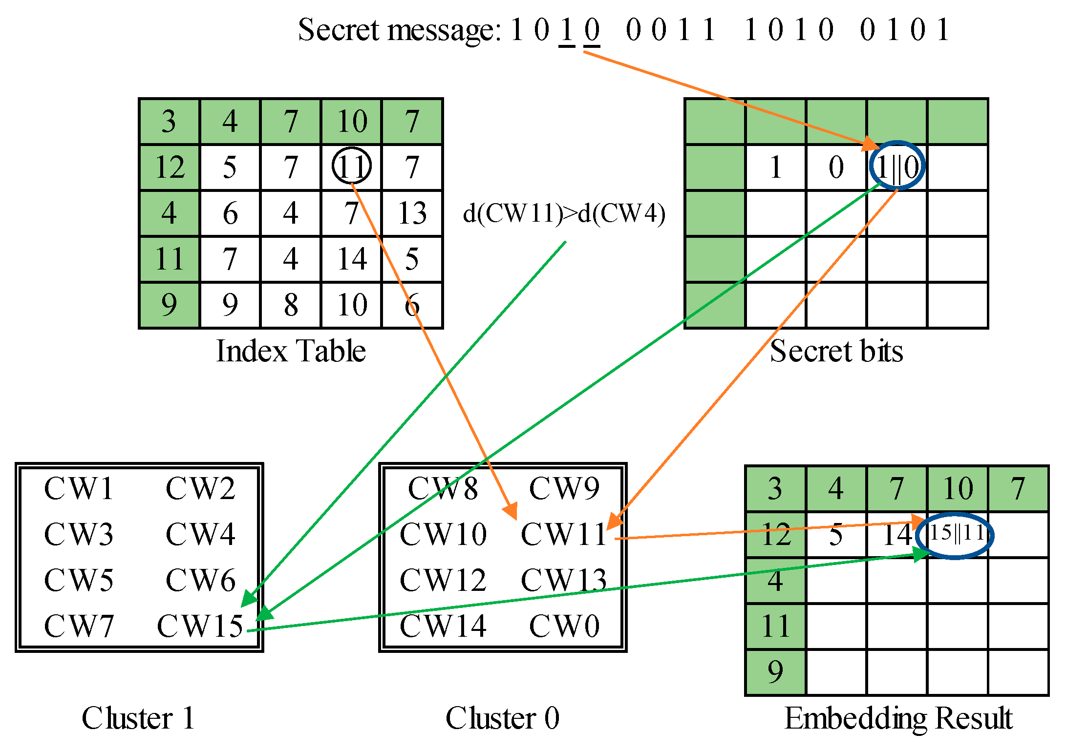
We use three typical examples to demonstrate the embedding process of the proposed data hiding scheme. The first example is shown in Figure 8. The index value is ‘CW5’ and the secret bit to be embedded is ‘1’. Since and the cluster label matches with the secret bit, i.e., , the secret bit is embedded without any modification. The second example is shown in Figure 9. The index value is ‘CW7’ and the secret bit to be embedded is ‘0’. Again, this is a normal image block according to the side-match evaluation. Since the cluster label mismatches the secret bit, i.e.,, the secret bit is embedded by recording its counterpart ‘CW14’ obtained through the pre-defined mapping between clusters. The third example is shown in Figure 10. In this case, the side-match evaluation, , indicates the occurrence of an abnormal block. Since the secret bit to be embedded is ‘1’, the rear codeword ‘CW15’ is recorded. In addition, the next secret bit ‘0’ is embedded by recording the matched current index ‘CW11’.
3.3. The SOC Compression and the Second Layer of Data Embedding Processes
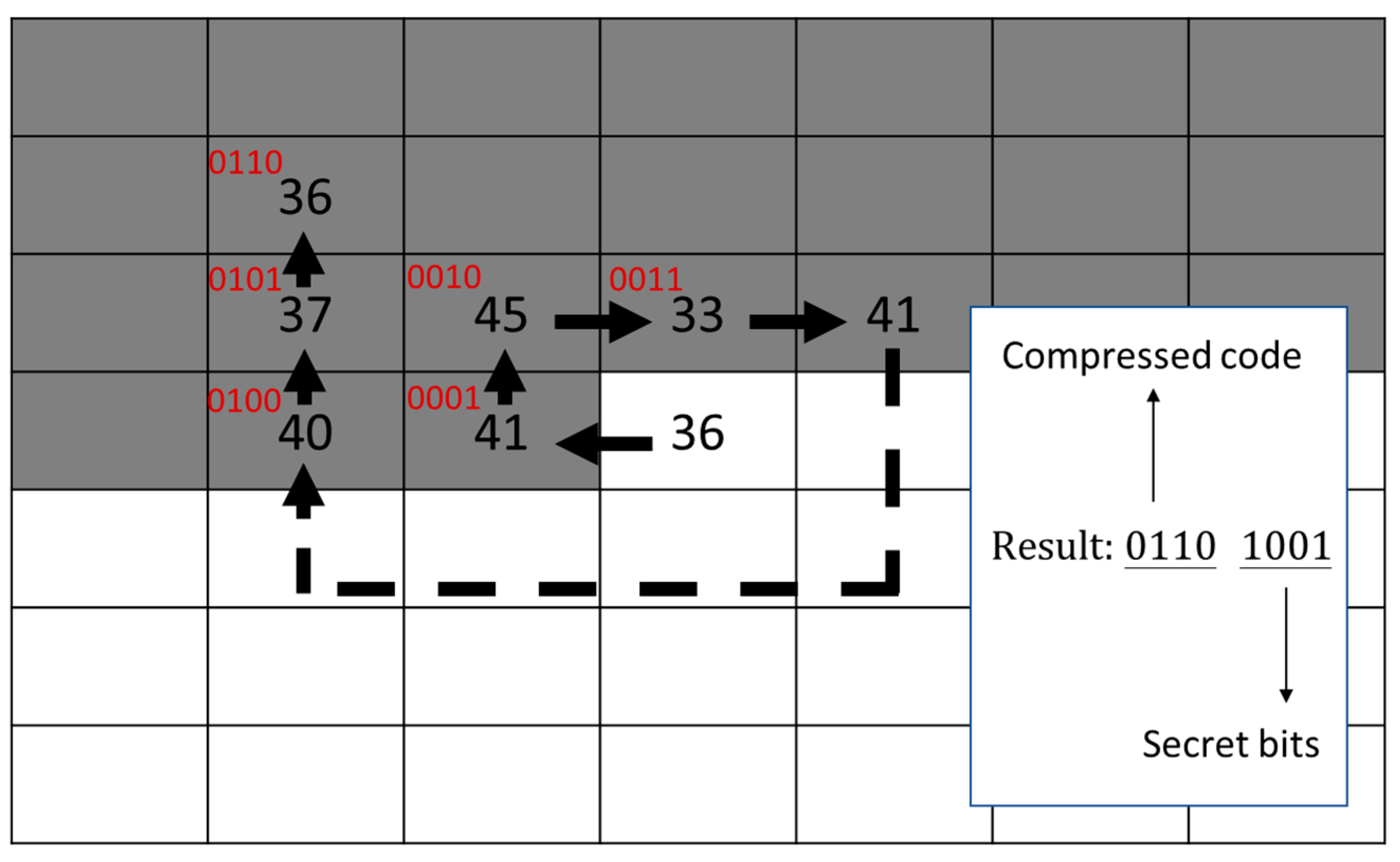
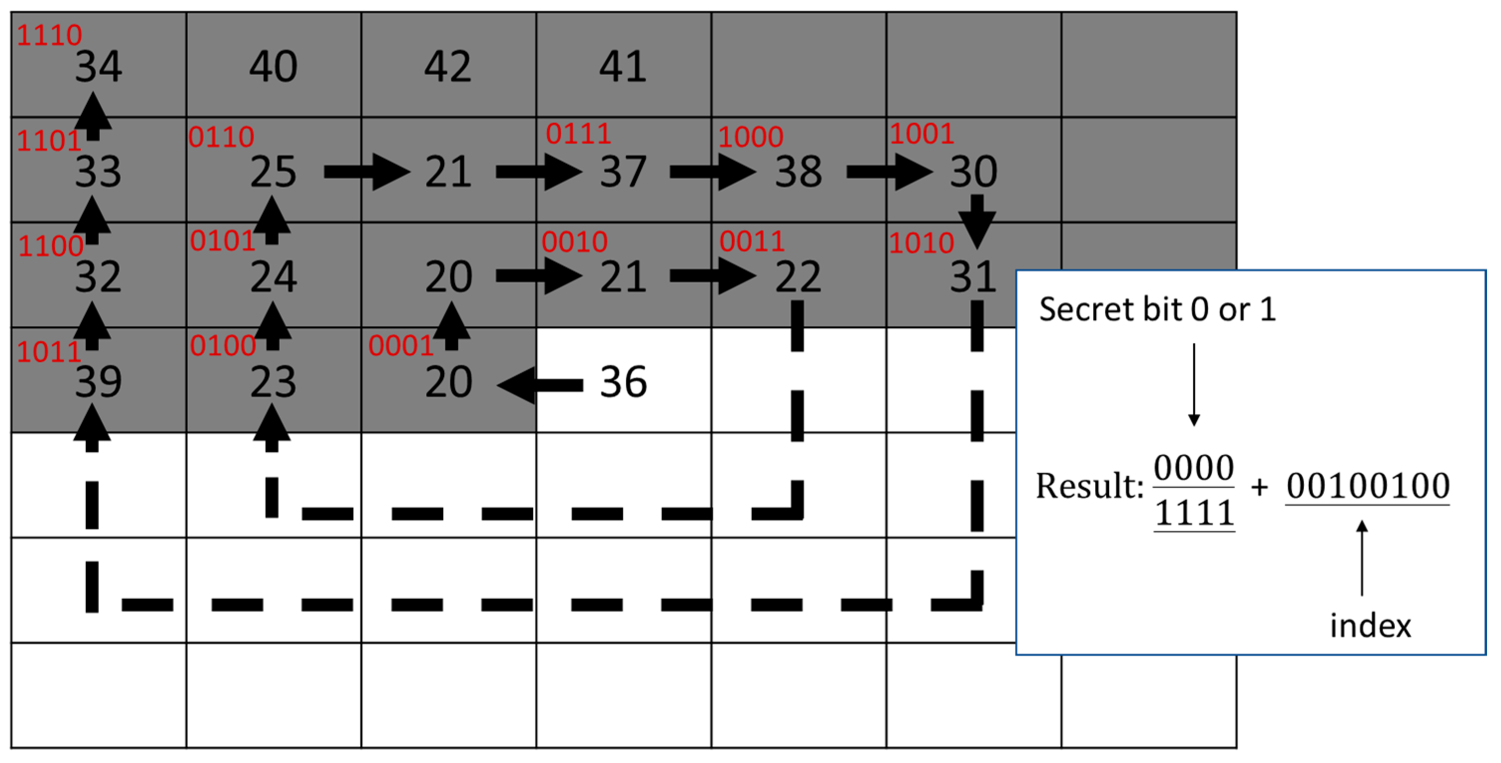
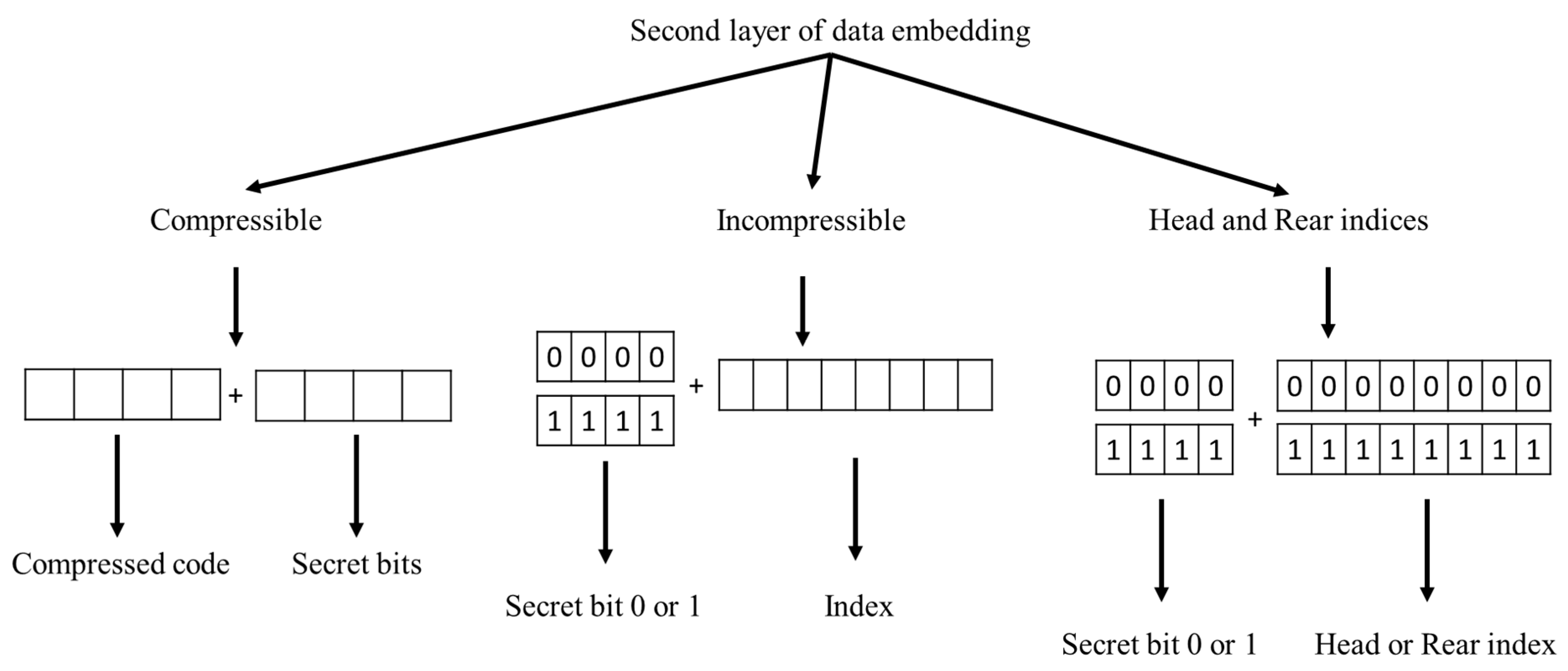
After the first layer embedding of secret data, the stego index table is sent to the indicator-free SOC compression process. To improve the efficiency of SOC, the indicator-elimination technique proposed by Chang et al. [31] is adopted. Two examples are applied to illustrate the SOC with an indicator-free method. The code length is set to four bits. However, the head and rear codes ‘0000’ and ‘1111’ are reserved for special usage. For a compressible index as shown in Figure 11, the coding is the same as the method introduced in Section 2.2, except that the label is started with ‘0001’ instead of ‘0000’. Besides, four secret bits are appended to camouflage a regular VQ index. For an incompressible index as shown in Figure 12, no matched index can be found in the predefined range of ‘0001’ to ‘1110’. One secret bit is embedded by putting a reserved code, ‘0000’ for ‘0’ and ‘1111’ for ‘1’. Then, the actual index is appended behind. To avoid confusing in the decoding process, the head and the rear indices in the first layer of embedding are treated as incompressible indices. The overall scheme of the proposed SOC and second layer of data embedding is illustrated in Figure 13, where the code length of VQ compression is assumed to be eight bits. The algorithm for SOC compression and the second layer of data embedding is given as Algorithm 2. Note that the tracing path of the indices near boundary of the index table may encounter the out-of-boundary problem. For such a case, the tracing is stopped and it treats the index under processing as incompressible. For instance, the indices in the first column are always incompressible according to this rule, since the first index to be checked is missing.
| Algorithm 2 SOC and the second-layer of data embedding for stego VQ index table. |
| Input: 1-st stego index table , secret data . Output: 2-nd (final) stego index table . 1: Stream cypher the secret data . 2: For each index , 3: If is SOC compressible, 4: Record by a label of 4 bits. 5: Retrieve 4 bits from and append to the label. 6: Record the 8 bits to . 7: Else ( is SOC incompressible or head or rear index of VQ) 8: Retrieve a secret bit from . 9: If , and record + to ; 10: Else (), and record + to . End 11: End 12: End |
3.4. Secret Data Extraction and Index Table Recovery Processes
The secret data extraction rules can be designed based on the embedding rules. At the receiver end, the extraction of the second layer secret data and the SOC decoding is executed first. Then, the indices are processed sequentially to determine the embedded second layer data and the original index value. The cluster label of the marked index is retrieved as the secret bit. The side-match values of the marked index and its counterpart are evaluated and compared to determine the original index value. When a reserved index is encountered, the head index represents ‘0’, while the rear index represents ‘1’. In addition, its succeeding index should be recovered with abnormal solution after extracting the secret bit. The algorithm for secret data extraction and index table recovery is summarized as Algorithm 3.
| Algorithm 3 Secret data extraction and index table recovery for de-clustering scheme. |
| Input: stego index table , specialized codebook , codeword mapping Output: function . cover index table , secret data . 1: Phase 1: Execute SOC decoding and extract the 2-nd layer of secret data. 2: While is not empty, 3: Retrieve 4 bits from . 4: If , 5: Decode into by SOC and clip 4 bits of secret data from . 6: Else 7: Extract 1 bit of secret data (0 for ‘0000’ and 1 for ‘1111’). 8: Clip an index code from . 9: End 10: Record to and secret bits to . End 11: Phase 2: Recover VQ index table and extract the 1-st layer of secret data. 12: For each index , 13: IF , 14: Find its cluster label and counterpart . 15: Extract secret bit and record to . 16: If , record to ; else record to . End 17: Else 18: If , record ‘0’ to ; else , record ‘1’ to . End 19: Find its cluster label and counterpart . 20: Extract secret bit and record to . 21: If , record to ; else record to . End 22: End 23: End Stream cypher to decode. |
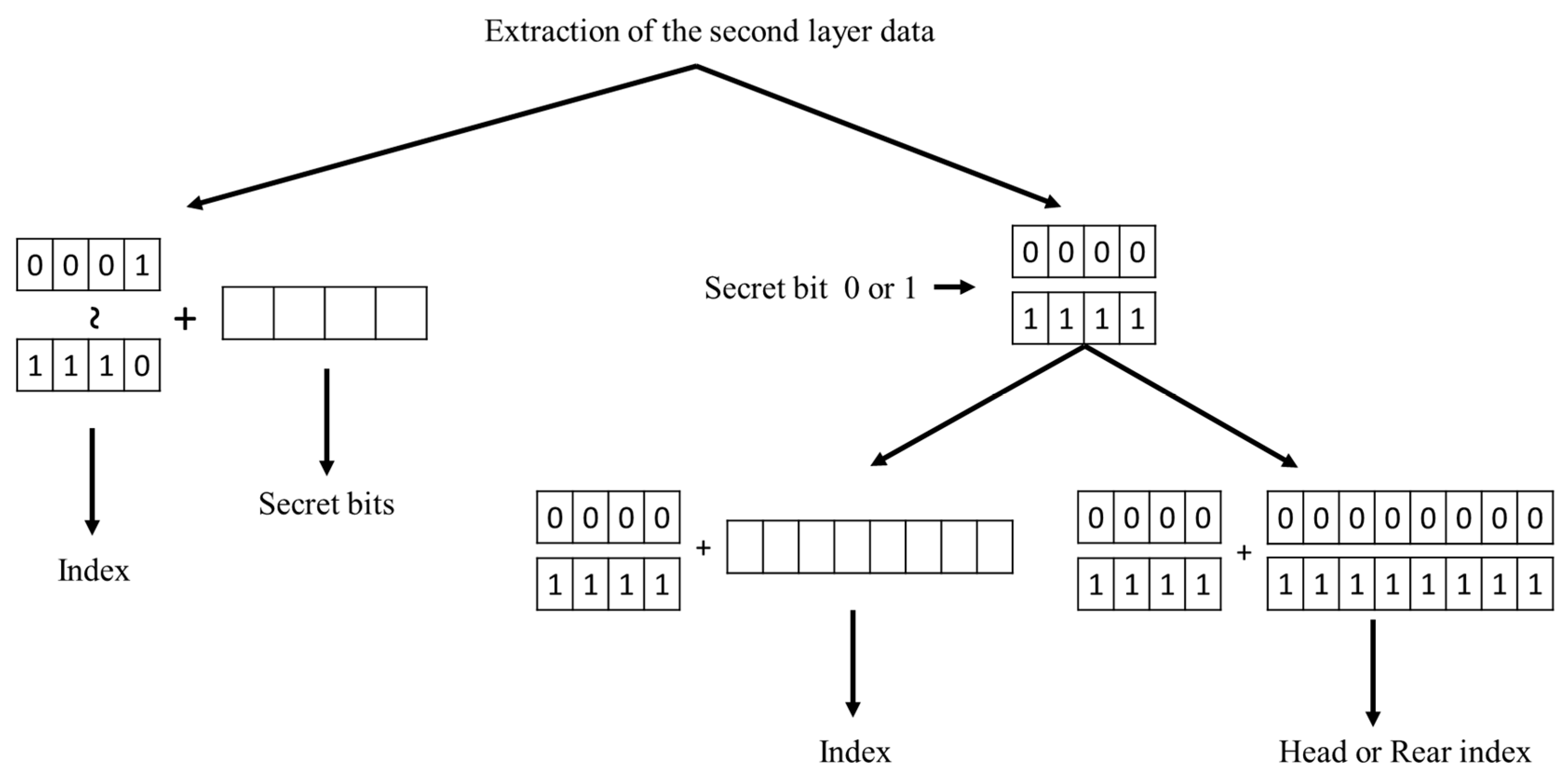
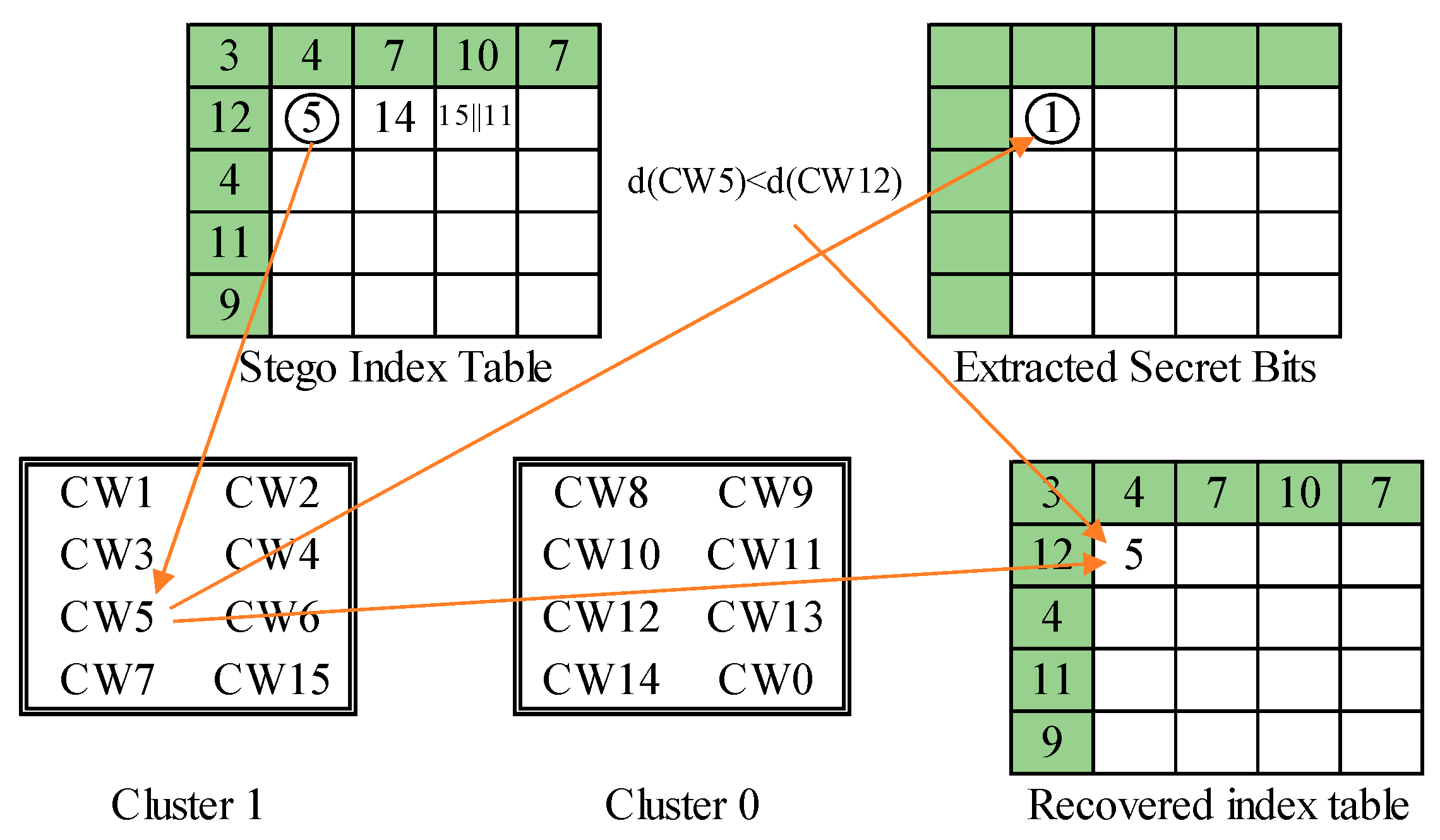
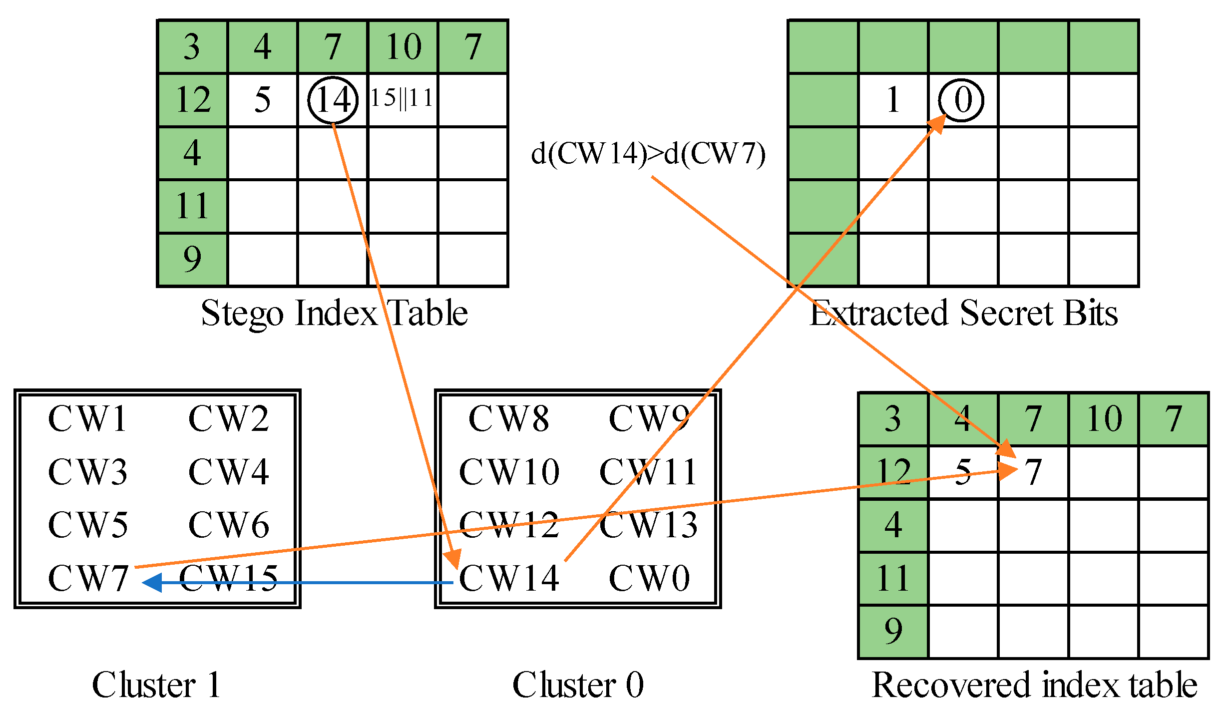
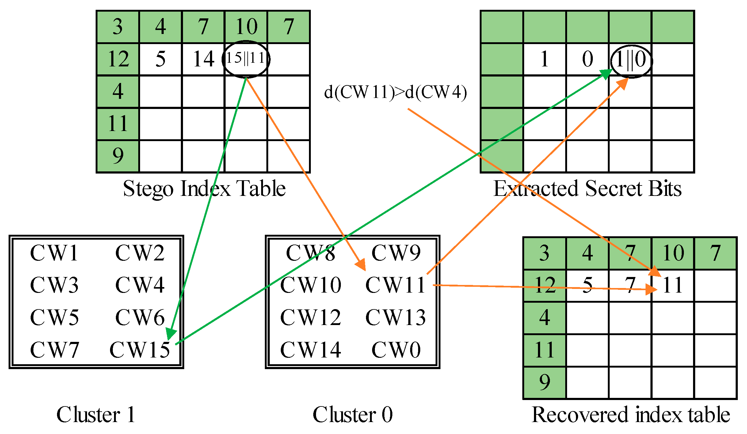
The overall scheme of phase 1 process is illustrated in Figure 14. The three examples presented in the embedding process of the first layer are applied to demonstrate the secret data extraction and index table recovery in the second phase. The first example is shown in Figure 15. We get the marked index ‘CW5’. The embedded secret bit is determined by . Then, its counterpart ‘CW12’ is retrieved, and their side-match values are compared. Since , ‘CW5’ is recorded to the recovered index table. The second example is shown in Figure 16. The marked index is ‘CW14’, whose cluster label 0 is retrieved as the secret bit. The side-match values of ‘CW14’ and its counterpart ‘CW7’ are calculated and compared. Since ‘CW7’ best matches the current environment, it is recorded to the recovered index table. The final example is shown in Figure 17. A rear index ‘CW15’ is encountered. It means a secret bit ‘1’ is embedded and the current block is abnormal. Its succeeding index ‘CW11’ is then retrieved. The cluster label 0 of ‘CW11’ is retrieved as the second secret bit. At last, the side-match values of ‘CW11’ and ‘CW4’ are compared. The mismatched index ‘CW11’ is recorded since the current block is indicated as an abnormal one.
4. Experimental Results
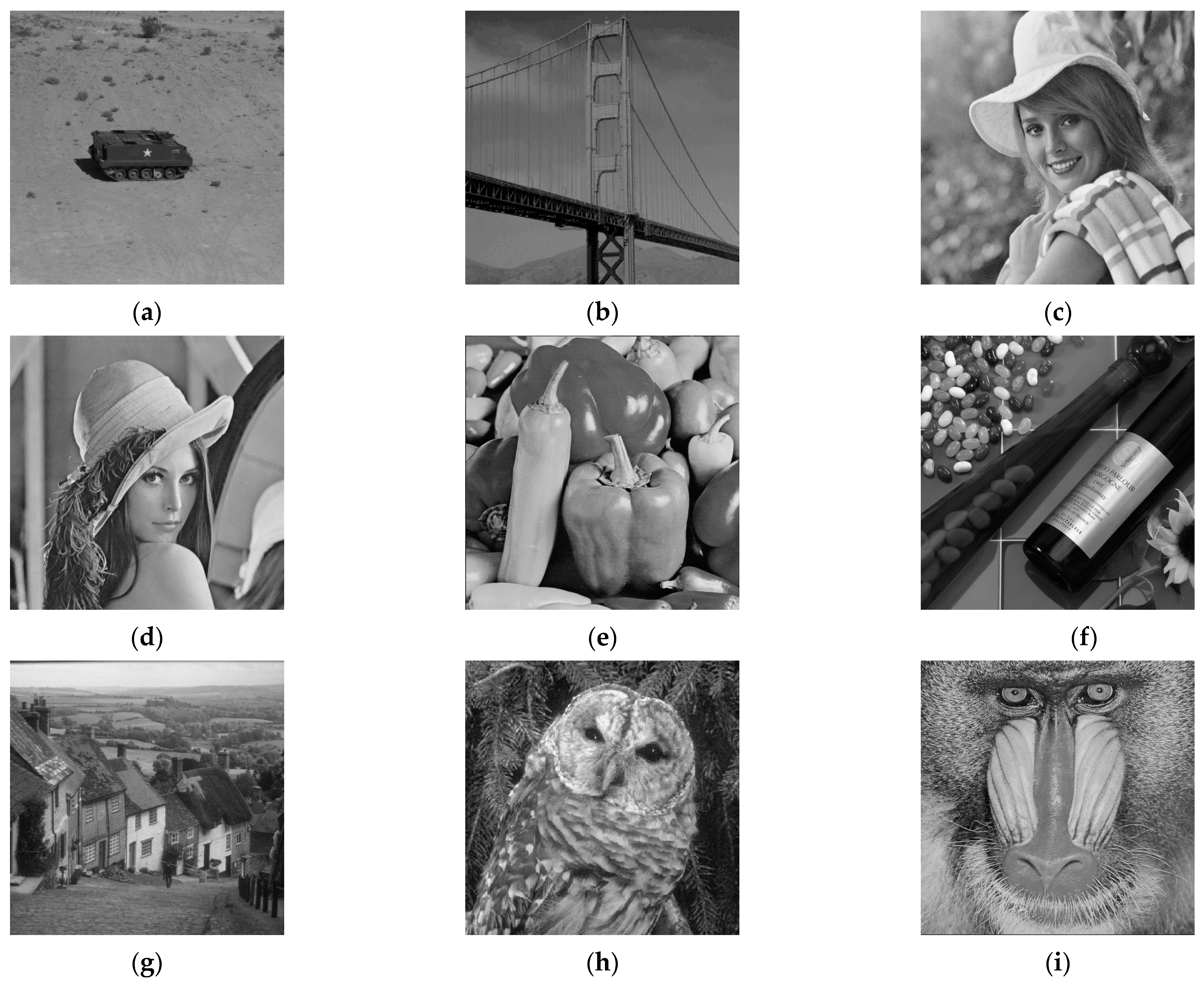
In our experiment, nine standard gray level images including (a) Tank, (b) Bridge, (c) Elaine, (d) Lena, (e) Peppers, (f) Wine, (g) Goldhill, (h) Bird, and (i) Baboon, as shown in Figure 18, are applied, each of them is sized as . VQ compression is executed with a codebook of length 256, and all images are divided into blocks of size . Images of different features, smooth or complex, are included. The platform for implementation are Intel Core i5-9400F CPU at 2.90 GHz and an 8 GB RAM personal computer with Windows 10 Professional operating system. The output of three processing steps for data hider are investigated, which are the visual quality of VQ images, the effectiveness of side-match evaluation, and the compression performance of SOC technique.
4.1. Visual Quality of VQ Images
VQ compression is a widely applied image compression technique. The major difference in our application is that although the length of codebook is a typical size of 256, only 254 codewords are available during the training process. The remaining two codewords, the head and the rear ones, are dummies and reserved for special usage. Based on this formulation, the quality of VQ approximation is evaluated. We adopt the peak-signal-to-noise-ratio (PSNR) as the performance metric, which is defined by
and the mean-square-error (MSE) is defined by
The notations and represent the original image and the VQ-decompressed image, respectively. The PSNR values of the VQ images produced with our specialized codebook are listed in Table 1. The image quality is very close to the conventional VQ compression with a codebook of length .
4.2. Effectiveness of Side-Match Evaluation
The performance of the proposed scheme is highly dependent on the side-match evaluation. To know the effectiveness of side-match evaluation for different images, the number of abnormal blocks detected in all test images are listed in Table 2. In our experiment, each test image is divided into blocks in total. In the worst case of ‘Baboon’ image, only 2.3% of total image blocks are detected to be abnormal. In the best case of ‘Bridge’ image, only one block is abnormal. These results ensure good performance of the proposed reversible data hiding scheme.
4.3. Performance of SOC Encoding
After switching the index value between clusters during embedding, the marked index table is sent to SOC encoding. Since the switching for embedding intends to disrupt the continuity between adjacent blocks for reversibility, such operation reduces the applicability of SOC encoding. In our experiment, the assigned length of search order code is four bits. Based on this parameter setting, the number of SOC compressible and uncompressible blocks for the test images are listed in Table 3. The compressible percentage ranges from 25.5% for Baboon to 88.3% for Bridge and is highly dependent on the feature of cover image. An index in a smooth image is more likely to find the same value in its neighbors and be compressed by SOC. On the other hand, an index in a complex image is frequently uncompressible. The total file size in bytes and image bit rate in bits per pixel are also listed in the table. The resulting file size is larger for an image with more uncompressible blocks. The embedding capacity in bits for different layers of the proposed scheme are listed in Table 4.
4.4. Comparison with Related Works
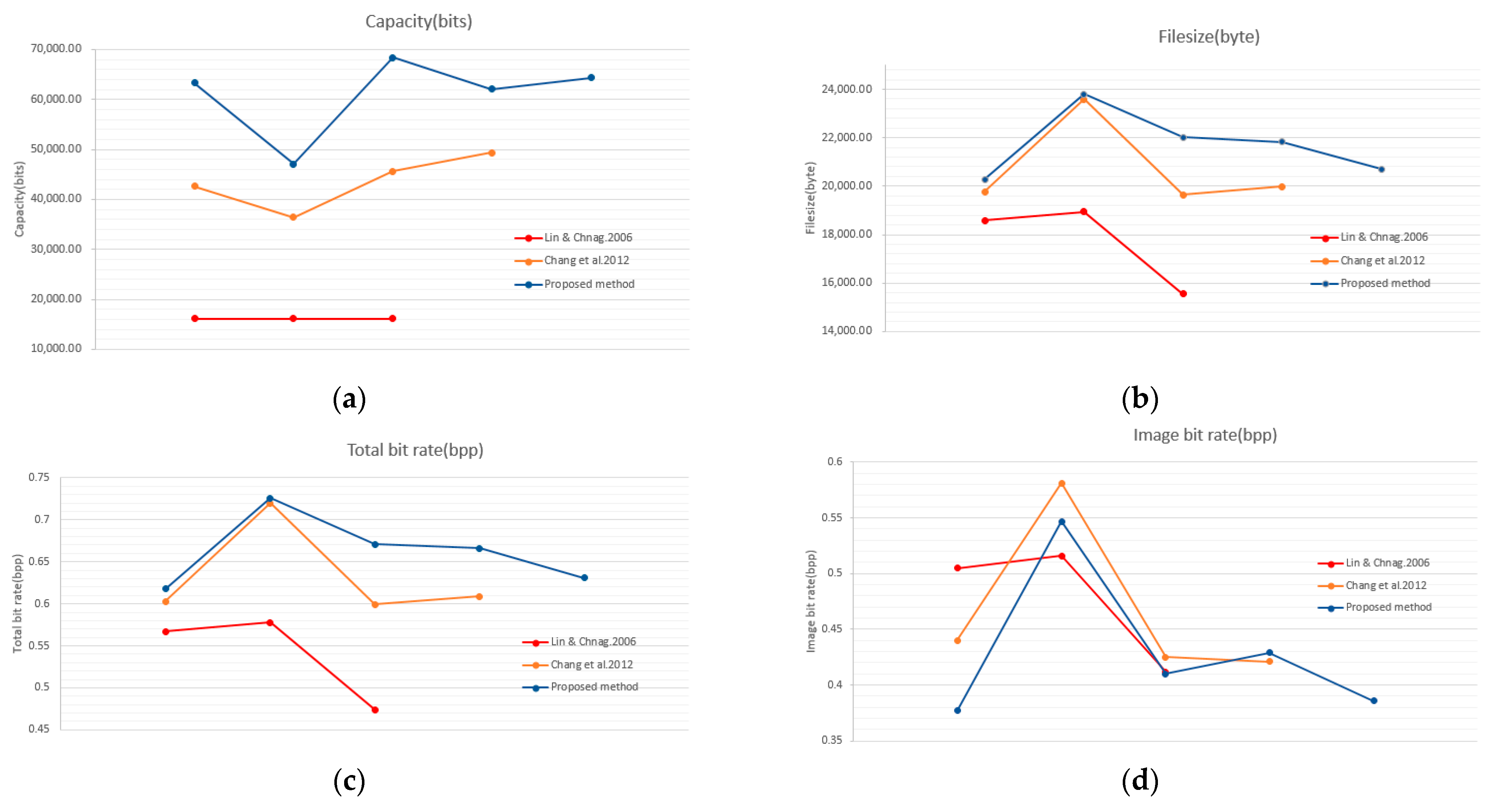
Since the proposed two-layer RDH scheme for VQ index table is a hybrid method of de-clustering and SOC-based schemes, our experimental results are compared with the two series of schemes. The first series are the de-clustering approaches. Table 5 compares the embedding capacity (EC) and file size of the proposed scheme with the schemes proposed in [28,30]. Although the series of schemes are all based on the VQ index table, the file size of marked index table are different. Usually, a larger file size is required to embed more secret data. To make a fair comparison, the EC and file size are converted to the total bitrate (total BR) and data bitrate (data BR) as listed in Table 6.
Since the secret data is usually assumed to be completely random, which is supposed to be uncompressible. Therefore, image bitrate (image BR), that represents compression efficiency of a scheme, can be estimated by subtracting the data bitrate from the total bitrate of a marked VQ index table. These performance evaluations are plotted in Figure 19. As shown in the figure, the proposed scheme can embed a large amount of data with a comparable file size. More specifically, in addition to the first layer of de-clustering embedding, SOC compression in the second embedding phase efficiently vacates a large room for hiding data. Figure 19b shows that the proposed scheme successfully camouflages an uncompressed VQ index table.
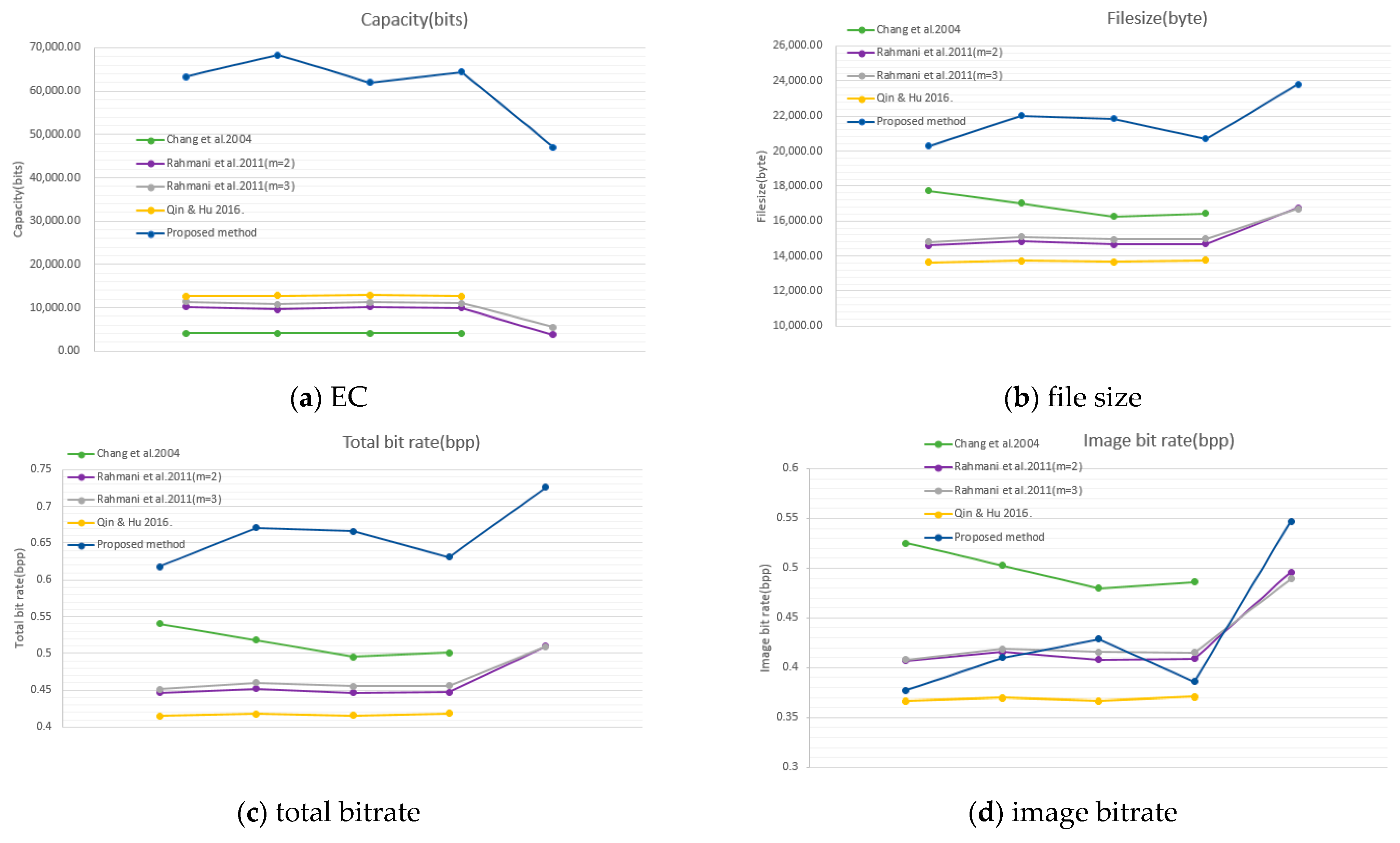
The second series to be compared are the SOC-based approaches, including [20,21,23]. EC and file size are listed in Table 7. Again, the total BR, data BR, and image BR are compared and listed in Table 8. Table values are plotted in Figure 20 for convenience of observation. As shown in the figure, the proposed scheme provides a large amount of EC, since the vacated room by compression is exploited to embed secret data. However, Figure 20d shows that the compression efficiency is comparable with related works. In addition, the IFSOC applied in our scheme is free from indicator. The series of SOC-based schemes directly hide secret data into indicators, which are exposed to eavesdroppers. So, the proposed indicator free RDH scheme is more secure than the related works.
5. Conclusions
A two-layer RDH scheme for VQ index table based on de-clustering and IFSOC is proposed. After data embedding by de-clustering, IFSOC is applied to compress the marked index table and embed the second layer of data at the same time. The total embedding capacity is satisfactory. In addition, the compression after de-clustering embedding increases the security of the first layer data, while the indicator free SOC secures the second layer data.
Experimental results show that the proposed RDH scheme outperforms state-of-the-art schemes under the overall evaluation of embedding capacity and image bit rate. Hybrid RDH scheme is a promising approach. By compressing VQ index followed by appending secret bits can successfully camouflage the original VQ index and create a high embedding capacity.
Author Contributions
Conceptualization, C.-C.C.; Methodology, C.-C.C.; Software, J.-F.C. and W.-J.K.; Validation, J.-H.H. and C.-C.C.; Formal analysis, J.-H.H.; Investigation, J.-H.H.; Resources, C.-C.C.; Data curation, J.-F.C. and W.-J.K.; Writing—original draft preparation, J.-H.H.; Writing—review and editing, C.-C.C.; Visualization, J.-H.H.; Supervision, C.-C.C.; Project administration, C.-C.C.; Funding acquisition, J.-H.H. All authors have read and agreed to the published version of the manuscript.
Funding
This research was funded by the Ministry of Science and Technology of Taiwan, grant number MOST 110-2221-E-507-003.
Institutional Review Board Statement
Not applicable.
Informed Consent Statement
Not applicable.
Data Availability Statement
The authors confirm that the data supporting the findings of this study are available within the article.
Conflicts of Interest
The authors declare no conflicts of interest.
References
- Chang, C.C.; Liu, Y.; Nguyen, T.S. A Novel Turtle Shell Based Scheme for Data Hiding. In Proceedings of the 2014 International Conference on Intelligent Information Hiding and Multimedia Signal Processing, Kita Kyushu, Japan, 27–29 August 2014; pp. 89–93. [Google Scholar] [CrossRef]
- Chang, C.C.; Li, C.T. Algebraic secret sharing using privacy homomorphisms for IoT-based healthcare systems. Math. Biosci. Eng. 2019, 16, 3367–3381. [Google Scholar] [CrossRef]
- Chi, H.; Chang, C.-C.; Liu, Y. An SMVQ compressed data hiding scheme based on multiple linear regression prediction. Connect. Sci. 2021, 33, 495–514. [Google Scholar] [CrossRef]
- Xiao, T.; Han, D.; He, J.; Li, K.-C.; de Mello, R.F. Multi-Keyword ranked search based on mapping set matching in cloud ciphertext storage system. Connect. Sci. 2021, 33, 95–112. [Google Scholar] [CrossRef]
- Chang, C.-C.; Li, C.-T.; Shi, Y.-Q. Privacy-Aware Reversible Watermarking in Cloud Computing Environments. IEEE Access 2018, 6, 70720–70733. [Google Scholar] [CrossRef]
- Chang, C.-C.; Li, C.-T.; Chen, K. Privacy-Preserving Reversible Information Hiding Based on Arithmetic of Quadratic Residues. IEEE Access 2019, 7, 54117–54132. [Google Scholar] [CrossRef]
- Xu, S.; Chang, C.-C.; Liu, Y. A high-capacity reversible data hiding scheme for encrypted images employing vector quantization prediction. Multimed. Tools Appl. 2021, 80, 20307–20325. [Google Scholar] [CrossRef]
- Carpentieri, B.; Castiglione, A.; De Santis, A.; Palmieri, F.; Pizzolante, R. One-pass lossless data hiding and compression of remote sensing data. Futur. Gener. Comput. Syst. 2019, 90, 222–239. [Google Scholar] [CrossRef]
- Mielikainen, J. LSB matching revisited. IEEE Signal. Process. Lett. 2006, 13, 285–287. [Google Scholar] [CrossRef]
- Chang, C.C.; Chou, Y.C.; Kieu, T.D. An Information Hiding Scheme Using Sudoku. In Proceedings of the Third International Conference on Innova-tive Computing, Information and Control, Dalian, China, 18–20 June 2008; pp. 17–22. [Google Scholar] [CrossRef]
- Chang, C.-C.; Horng, J.-H.; Shih, C.-S.; Wang, X. VQ-oriented data hiding based on adjustable error compensation strategy. Connect. Sci. 2021, 1–19. [Google Scholar] [CrossRef]
- Xie, X.-Z.; Chang, C.-C.; Horng, J.-H. An EMD-based data hiding scheme for JPEG images. Connect. Sci. 2021, 33, 515–531. [Google Scholar] [CrossRef]
- Gray, R. Vector quantization. IEEE Assp. Mag. 1984, 1, 4–29. [Google Scholar] [CrossRef]
- Wallace, G. The JPEG still picture compression standard. IEEE Trans. Consum. Electron. 1992, 38, XVIII–XXXIV. [Google Scholar] [CrossRef]
- Xu, S.; Chang, C.-C.; Liu, Y. A novel image compression technology based on vector quantisation and linear regression prediction. Connect. Sci. 2021, 33, 219–236. [Google Scholar] [CrossRef]
- Chang, C.C.; Sung, C.H.; Chen, T.S. A locally adaptive scheme for image index compression. In Proceedings of the 1997 Conference on Computer Vision, Graphics, and Image Processing, Taichung, Taiwan, August 1997; pp. 93–99. [Google Scholar]
- Hsieh, C.-H.; Tsai, J.-C. Lossless compression of VQ index with search-order coding. IEEE Trans. Image Process. 1996, 5, 1579–1582. [Google Scholar] [CrossRef]
- Linde, Y.; Buzo, A.; Gray, R. An Algorithm for Vector Quantizer Design. IEEE Trans. Commun. 1980, 28, 84–95. [Google Scholar] [CrossRef] [Green Version]
- Kim, T. Side match and overlap match vector quantizers for images. IEEE Trans. Image Process. 1992, 1, 170–185. [Google Scholar] [CrossRef]
- Chang, C.-C.; Chen, G.-M.; Lin, M.-H. Information hiding based on search-order coding for VQ indices. Pattern Recognit. Lett. 2004, 25, 1253–1261. [Google Scholar] [CrossRef]
- Rahmani, P.; Dastghaibyfard, G.; Rahmani, E. A reversible data embedding scheme based on search order coding for VQ index tables. In Proceedings of the 8th International ISC Conference on Information Security and Cryptology, Mashhad, Iran, 14–15 September 2011; pp. 79–82. [Google Scholar]
- Hu, Y.C.; Shu, Y.Y.; Chen, Y.S.; Su, B.H. Reversible data hiding method based on the coding of VQ index table. In Proceedings of the E-learning and Information Technology Symposium, Tainan, Taiwan, 25 March 2015. [Google Scholar]
- Qin, C.; Hu, Y.-C. Reversible data hiding in VQ index table with lossless coding and adaptive switching mechanism. Signal. Process. 2016, 129, 48–55. [Google Scholar] [CrossRef]
- Lee, J.-D.; Chiou, Y.-H.; Guo, J.-M. Lossless data hiding for VQ indices based on neighboring correlation. Inf. Sci. 2013, 221, 419–438. [Google Scholar] [CrossRef]
- Lee, J.-D.; Chiou, Y.-H.; Guo, J.-M. Information Hiding Based on Block Match Coding for Vector Quantization-Compressed Images. IEEE Syst. J. 2014, 8, 737–748. [Google Scholar] [CrossRef]
- Lin, C.-C.; Liu, X.-L.; Yuan, S.-M. Reversible data hiding for VQ-compressed images based on search-order coding and state-codebook mapping. Inf. Sci. 2015, 293, 314–326. [Google Scholar] [CrossRef]
- Rahmani, P.; Dastghaibyfard, G. An efficient histogram-based index mapping mechanism for reversible data hiding in VQ-compressed images. Inf. Sci. 2018, 435, 224–239. [Google Scholar] [CrossRef]
- Lin, C.Y.; Chang, C.C. Hiding data in VQ-compressed images using dissimilar pairs. J. Comput. 2006, 17, 3–10. [Google Scholar]
- Chang, C.-C.; Hsieh, Y.-P.; Lin, C.-Y. Lossless Data Embedding with High Embedding Capacity Based on Declustering for VQ-Compressed Codes. IEEE Trans. Inf. Forensics Secur. 2007, 2, 341–349. [Google Scholar] [CrossRef]
- Chang, C.-C.; Lin, C.-Y.; Hsieh, Y.-P. Data hiding for vector quantization images using mixed-base notation and dissimilar patterns without loss of fidelity. Inf. Sci. 2012, 201, 70–79. [Google Scholar] [CrossRef]
- Chang, C.-C.; Chou, Y.-C.; Hsieh, Y.-P. Search-order coding method with indicator-elimination property. J. Syst. Softw. 2009, 82, 516–525. [Google Scholar] [CrossRef]
Figure 1.
An illustration of VQ image compression, where is the block size; is the codeword length of the codebook; , , and are the indices of the leading blocks.
Figure 1.
An illustration of VQ image compression, where is the block size; is the codeword length of the codebook; , , and are the indices of the leading blocks.

Figure 2.
Illustration of the search order.

Figure 3.
An example of SOC.

Figure 4.
The flowchart of the proposed scheme.

Figure 5.
Illustration of the codebook sorting.

Figure 6.
An illustration of codewords clustering.

Figure 7.
Illustration of the side-match evaluation.

Figure 8.
Embedding example 1: matched case.

Figure 9.
Embedding example 2: mismatched case.

Figure 10.
Embedding example 3: abnormal block.

Figure 11.
Embedding example 1: compressible index.

Figure 12.
Embedding example 2: incompressible index.

Figure 13.
The second layer of data embedding.

Figure 14.
The extraction of the second layer secret data.

Figure 15.
Extraction example 1: matched case.

Figure 16.
Extraction example 2: mismatched case.

Figure 17.
Extraction example 3: abnormal block.

Figure 18.
Nine standard grayscale test images applied in our experiment. Tank (a), Bridge (b), Elaine (c), Lena (d), Peppers (e), Wine (f), Goldhill (g), Bird (h), Baboon (i).
Figure 18.
Nine standard grayscale test images applied in our experiment. Tank (a), Bridge (b), Elaine (c), Lena (d), Peppers (e), Wine (f), Goldhill (g), Bird (h), Baboon (i).

Figure 19.
Comparisons with de-clustering RDH schemes. EC (a), file size (b), total bitrate (c), image bitrate (d).
Figure 19.
Comparisons with de-clustering RDH schemes. EC (a), file size (b), total bitrate (c), image bitrate (d).

Figure 20.
Comparisons with SOC-based RDH schemes. EC (a), file size (b), total bitrate (c), image bitrate (d).
Figure 20.
Comparisons with SOC-based RDH schemes. EC (a), file size (b), total bitrate (c), image bitrate (d).


Table 1.
PSNR values of the VQ images produced with our codebook.
| Images | PSNR (dB) | Images | PSNR (dB) | Images | PSNR (dB) |
|---|---|---|---|---|---|
| Tank | 31.75 | Lena | 30.66 | Goldhill | 29.89 |
| Bridge | 31.86 | Peppers | 30.49 | Bird | 26.45 |
| Elaine | 30.69 | Wine | 30.16 | Baboon | 25.59 |
Table 2.
Number of abnormal blocks detected by side-match evaluation.
| Images | Abnormal Blocks | Images | Abnormal Blocks | Images | Abnormal Blocks |
|---|---|---|---|---|---|
| Tank | 7 | Lena | 147 | Goldhill | 91 |
| Bridge | 1 | Peppers | 128 | Bird | 180 |
| Elaine | 85 | Wine | 142 | Baboon | 373 |
Table 3.
Number of SOC compressible and uncompressible blocks.
| Images | Compressible | Uncompressible | File Size | Bit Rate |
|---|---|---|---|---|
| Tank | 13,016 | 3368 | 18,113 | 0.55 |
| Bridge | 14,472 | 1912 | 17,361 | 0.52 |
| Elaine | 8638 | 7746 | 20,761 | 0.63 |
| Lena | 9889 | 6495 | 20,279 | 0.61 |
| Peppers | 9562 | 6822 | 22,013 | 0.67 |
| Wine | 11,240 | 5144 | 19,709 | 0.60 |
| Goldhill | 8294 | 8090 | 20,775 | 0.63 |
| Bird | 6295 | 10,089 | 22,177 | 0.46 |
| Baboon | 4179 | 12,205 | 23,809 | 0.67 |
Table 4.
Embedding capacity for different layers of the proposed scheme (bits).
| Images | Layer 1 | Layer 2 | Total |
|---|---|---|---|
| Tank | 16,414 | 55,462 | 71,876 |
| Bridge | 16,398 | 59,814 | 76,212 |
| Elaine | 16,720 | 42,814 | 59,534 |
| Lena | 16,816 | 46,483 | 63,299 |
| Peppers | 16,863 | 51,549 | 68,412 |
| Wine | 16,886 | 50,606 | 67,492 |
| Goldhill | 16,615 | 41,497 | 58,112 |
| Bird | 16,883 | 35,768 | 52,651 |
| Baboon | 17,266 | 29,803 | 47,069 |
Table 5.
Comparisons of EC and file size with de-clustering schemes.
| Image | [28] | [30] | Proposed Scheme | |
|---|---|---|---|---|
| Airplane | EC (bits) | — | 49,394 | 62,066 |
| File size (bytes) | — | 19,982 | 21,838 | |
| Baboon | EC (bits) | 16,129 | 36,436 | 47,069 |
| File size (bytes) | 18,947 | 23,594 | 23,809 | |
| Boat | EC (bits) | — | — | 64,361 |
| File size (bytes) | — | — | 20,696 | |
| Lena | EC (bits) | 16,129 | 42,630 | 63,299 |
| File size (bytes) | 18,588 | 19,761 | 20,279 | |
| Peppers | EC (bits) | 16,129 | 45,623 | 68,412 |
| File size (bytes) | 15,548 | 19,644 | 22,013 |
Table 6.
Total bitrate, data bitrate, and image bitrate of de-clustering schemes.
| Image | [28] | [30] | Proposed Method | |
|---|---|---|---|---|
| Airplane | Total BR | — | 0.609 | 0.666 |
| Data BR | — | 0.188 | 0.236 | |
| Image BR | — | 0.421 | 0.429 | |
| Baboon | Total BR | 0.578 | 0.720 | 0.726 |
| Data BR | 0.061 | 0.138 | 0.179 | |
| Image BR | 0.516 | 0.581 | 0.547 | |
| Boat | Total BR | — | — | 0.631 |
| Data BR | — | — | 0.245 | |
| Image BR | — | — | 0.386 | |
| Lena | Total BR | 0.567 | 0.603 | 0.618 |
| Data BR | 0.061 | 0.162 | 0.241 | |
| Image BR | 0.505 | 0.440 | 0.377 | |
| Peppers | Total BR | 0.474 | 0.599 | 0.671 |
| Data BR | 0.061 | 0.174 | 0.260 | |
| Image BR | 0.412 | 0.425 | 0.410 |
Table 7.
Comparisons of EC and file size with SOC-based schemes.
| Image | [20] | [21] (m = 2) | [21] (m = 3) | [23] | Proposed Method | |
|---|---|---|---|---|---|---|
| Airplane | EC (bits) | 4096 | 10,208 | 11,348 | 12,933 | 62,066 |
| File size | 16,252 | 14,647 | 14,942 | 13,664 | 21,838 | |
| Baboon | EC (bits) | — | 3774 | 5482 | — | 47,069 |
| File size | — | 16,744 | 16,711 | — | 23,809 | |
| Boat | EC (bits) | 4096 | 10,007 | 10,993 | 12,671 | 64,361 |
| File size | 16,449 | 14,680 | 14,974 | 13,762 | 20,696 | |
| Lena | EC (bits) | 4096 | 10,183 | 11,390 | 12,770 | 63,299 |
| File size | 17,727 | 14,614 | 14,811 | 13,631 | 20,279 | |
| Peppers | EC (bits) | 4096 | 9586 | 10,787 | 12,803 | 68,412 |
| File size | 17,006 | 14,843 | 15,106 | 13,729 | 22,013 |
Table 8.
Total bitrate, data bitrate, and image bitrate of SOC-based schemes.
| Image | [20] | [21] (m = 2) | [21] (m = 3) | [23] | Proposed Method | |
|---|---|---|---|---|---|---|
| Airplane | Total BR | 0.495 | 0.446 | 0.455 | 0.416 | 0.666 |
| Data BR | 0.015 | 0.038 | 0.043 | 0.049 | 0.236 | |
| Image BR | 0.480 | 0.408 | 0.416 | 0.367 | 0.429 | |
| Baboon | Total BR | — | 0.510 | 0.509 | — | 0.726 |
| Data BR | — | 0.014 | 0.020 | — | 0.179 | |
| Image BR | — | 0.496 | 0.489 | — | 0.547 | |
| Boat | Total BR | 0.501 | 0.447 | 0.456 | 0.419 | 0.631 |
| Data BR | 0.015 | 0.038 | 0.041 | 0.048 | 0.245 | |
| Image BR | 0.486 | 0.409 | 0.415 | 0.371 | 0.386 | |
| Lena | Total BR | 0.540 | 0.446 | 0.451 | 0.415 | 0.618 |
| Data BR | 0.015 | 0.038 | 0.043 | 0.048 | 0.241 | |
| Image BR | 0.525 | 0.407 | 0.408 | 0.367 | 0.377 | |
| Peppers | Total BR | 0.518 | 0.452 | 0.460 | 0.418 | 0.671 |
| Data BR | 0.015 | 0.036 | 0.041 | 0.048 | 0.260 | |
| Image BR | 0.503 | 0.416 | 0.419 | 0.370 | 0.410 |
Publisher’s Note: MDPI stays neutral with regard to jurisdictional claims in published maps and institutional affiliations. |
© 2021 by the authors. Licensee MDPI, Basel, Switzerland. This article is an open access article distributed under the terms and conditions of the Creative Commons Attribution (CC BY) license (https://creativecommons.org/licenses/by/4.0/).
Share and Cite
MDPI and ACS Style
Chang, C.-C.; Chang, J.-F.; Kao, W.-J.; Horng, J.-H. Two-Layer Reversible Data Hiding for VQ-Compressed Images Based on De-Clustering and Indicator-Free Search-Order Coding. Future Internet 2021, 13, 215. https://doi.org/10.3390/fi13080215
AMA Style
Chang C-C, Chang J-F, Kao W-J, Horng J-H. Two-Layer Reversible Data Hiding for VQ-Compressed Images Based on De-Clustering and Indicator-Free Search-Order Coding. Future Internet. 2021; 13(8):215. https://doi.org/10.3390/fi13080215
Chicago/Turabian StyleChang, Chin-Chen, Jui-Feng Chang, Wei-Jiun Kao, and Ji-Hwei Horng. 2021. "Two-Layer Reversible Data Hiding for VQ-Compressed Images Based on De-Clustering and Indicator-Free Search-Order Coding" Future Internet 13, no. 8: 215. https://doi.org/10.3390/fi13080215
Note that from the first issue of 2016, this journal uses article numbers instead of page numbers. See further details here.