
A Method for Evaluating Coalbed Methane Reservoir Productivity Considering Drilling Fluid Damage

1
CNOOC Research Institute Ltd., CNOOC Building, Yard 6, Taiyanggong South Street, Chaoyang District, Beijing 100028, China
2
College of Geosciences and Surveying Engineering, China University of Mining & Technology, No. 11, Xueyuan Road, Haidian District, Beijing 100083, China
3
College of Mining Engineering, Taiyuan University of Technology, No. 79 Yingze Xi Street, Wanbolin District, Taiyuan 030002, China
4
School of Earth Resources, China University of Geosciences Wuhan, 388 Lumo Road, Wuhan 430074, China
*
Author to whom correspondence should be addressed.
Energies 2024, 17(7), 1686; https://doi.org/10.3390/en17071686
Submission received: 28 February 2024
/
Revised: 21 March 2024
/
Accepted: 28 March 2024
/
Published: 1 April 2024
(This article belongs to the Special Issue Advances in the Development of Unconventional Oil and Gas Resources)
Abstract
:In the process of coalbed methane development, drilling fluid and fracturing fluid cannot achieve absolute compatibility with formation. The incompatibility between the working fluid and reservoir will lead to the intrusion of working fluid into the reservoir and cause reservoir pollution. This is a very common phenomenon. There is a large amount of pulverized coal in the coal seam, and the intrusion of working liquid will be combined with the pulverized coal to form cement to block the seepage space in the reservoir. Since pressure relief and fracturing fluid backflow will be performed at the first time after fracturing, the intrusion range of the working fluid is small, generally reaching 10 m to 50 m. Compared with a conventional gas reservoir or shale gas reservoir, the working fluid loss during CBM development will seriously affect the subsequent production project and even make the gas well lose production capacity. On the other hand, in order to avoid this phenomenon, measures such as acidification or volumetric fracturing are sometimes used to improve the seepage environment near the well and near the fracture. The purpose of this study is to quantitatively evaluate the impacts of working fluid filtration and reservoir reconstruction on production. In this study, a single well productivity evaluation model and sensitivity analysis method considering drilling fluid filtration loss, fracturing fluid filtration loss, reservoir reconstruction and other processes is proposed. The formation mechanism of fluid loss during drilling and fracturing is described, and the productivity evaluation model considering fluid loss is combined with the Langmuir isothermal adsorption equation, steady-state diffusion law, Darcy’s seepage law and Duhamel convolution formation. Combined with the distribution of actual gas reservoir flow characteristics, the sensitivity of single well productivity to gas reservoir porosity, gas reservoir permeability, coal seam adsorption coefficient, working fluid filtration loss and reservoir reconstruction measures are analyzed. Through the analysis and fitting of the actual production data on site, the relationship curve can better fit the field production data, and the evaluation results are in line with the drilling and fracturing conditions at that time and the subsequent production conditions, with small errors. The obtained method is suitable for predicting the productivity of fractured vertical wells in different working conditions and provides a basis for the development and productivity prediction of CBM reservoirs in China and in international cooperation.
1. Introduction
Coalbed methane is considered to be one of the most dangerous sources in coal mining [1]. Scott believes that coalbed methane mainly exists in the microscopic pores of a coal matrix in the form of adsorbed gas under the formation conditions of a certain burial depth. In the process of coalbed methane mining, permeability decrease caused by increasing effective stress and a decreasing crack scale and permeability increase caused by coal matrix contraction and crack scale enlargement occur simultaneously [2]. At present, the development of coalbed methane in China is mainly concentrated in the shallow strata, and the burial depth is about 700–1500 m. The depth range of 700 m to 1500 m also results in a lower pressure than normal gas reservoirs. In the process of CBM development, the working fluid easily invades the formation. In the development of coalbed methane, special attention should be paid to the damage caused to the reservoir by the working fluid. Reservoir damage can greatly affect gas well productivity.
In the process of coalbed methane drilling and hydraulic fracturing, working fluid will enter the formation through the well wall, resulting in a filtration effect, which results in reservoir damage in the discharge area. The filtration effect will reduce the permeability near the well, requiring a greater production pressure differential to reach the bottom hole, which will significantly reduce the flow of gas to the bottom hole for the lower pressure coalbed methane reservoir. Based on a large number of experimental studies on filtration, Harrington qualitatively proposed an empirical formula for calculating the total amount of filtration loss from the fracturing fluid to the filtration surface during fracturing [3]. Cinco-Ley and Samaniego studied the damage caused by fluid loss to pressure and production in a vertically fractured well with limited conductivity and proposed a skin factor to quantify the damage caused by this fluid loss [4]. Jiao Guoying proposed using the thickness and permeability of the filtration zone to calculate the pseudo-skin coefficient of fracture surface damage [5]. In view of the limitations of hydraulic fracturing, such as the fast settling rate of the proppant near the wellbore, large filtration loss and reservoir damage, large water consumption and environmental pollution, foam fracturing has been used since the 1970s due to its strong sand carrying capacity, small filtration loss, small formation damage and good flowback effect. It has gradually been widely used in low-permeability, low-pressure and water-sensitive unconventional oil and gas reservoirs [6]. Yin Hongjun proposed conducting a productivity analysis when the wall damage of every point in the crack is the same. The analysis shows that the higher the skin factor, the lower the initial production of the fractured well. With the increase in the production time, the influence of the skin effect gradually disappeared [7]. Len and Barr believe that drilling fluid should not only keep the hole wall stable, but also minimize the damage to coal reservoirs in the process of low-porosity and low-pressure CBM drilling [8,9]. Zhao Jinzhou used the numerical simulation method to simulate fracture productivity under variable wall damage. However, this method is complicated in modeling and calculation [10]. Gao Shusheng proposed a coupling model of gas diffusion and seepage in the SRV region of adsorbent natural gas reservoirs and presented a numerical solution to the matrix–fracture network coupling mathematical model. This method has been applied in the Changning-Weiyuan A well area, and it is clear that increasing the volume fracturing scale and increasing the fracture network density in the SRV area are important means for the efficient development of shale gas reservoirs [11]. In order to explore stimulation and reconstruction technology suitable for the geological conditions of deep coal seams, Anqi took the Shenfu Block of the Ordos Basin as the geological background, took the large-scale volume fracturing of deep coal seams as the engineering practice, introduced the integrated post-compression evaluation method of geology, engineering and intelligence and adopted the dual intelligent fitting and correction of fracturing and productivity. The reservoir reconstruction volume (SRV) and gas discharge volume (DRV) are described in detail, and the final recoverable reserves in EUR under different fracturing scales and well types are predicted [12]. In order to solve the problem of the traditional three-dimensional static model being unable to predict the change in ground stress in the production process of strongly heterogeneous reservoirs, Liu Yingjun took the coalbed methane reservoir in the southeast of the Qinshui Basin as an example and focused on the evolution of four-dimensional ground stress under the conditions of coalbed methane mining. A subprogram for dynamic mapping between a finite difference flow rectangular orthogonal grid and a finite element geomechanical three-dimensional tetrahedral grid of a coalbed methane reservoir was created. By combining the heterogeneity of a coal rock reservoir and a geological model of a coalbed methane reservoir, a four-dimensional geostress multi-physical field precision model of a coalbed methane reservoir was established based on the integration of geological engineering [13]. Due to the fact that only the stress sensitivity effect is considered while the matrix pore shrinkage effect is ignored in CBM well productivity prediction, the productivity evaluation error is large. Based on the analysis of the non-Darcy effect and the coal matrix shrinkage effect, Li Futang (2022) established a CBM productivity prediction model considering pore compression and the matrix shrinkage effect [14]. Thamas believes that the reservoir can be protected by effectively sealing the formation with solid-free drilling fluid to control the fluid loss [15]. By using 45 nitrogen foam fracturing wells in the Lu ‘an mining area as the object, Li Hengle analyzed the type of fracturing construction curve and its influence on productivity, discussed the relationship between the amount of fracturing fluid and productivity at each stage and compared and evaluated the difference in productivity between nitrogen foam and hydraulic fracturing wells [16]. In order to discover the law of the influence of a geological structure on the gas production effect of coalbed methane wells, Zhang Xiaodong used the Changzhi Block in the Qinshui Basin as the research object, introduced the coal seam thickness differentiation coefficient to characterize the structural complexity, applied the analytic hierarchy process to evaluate the structural complexity coefficient of the block and divided the structural units according to this. By combining the results of the fuzzy mathematical analysis of the influence of geological conditions with the reservoir physical properties and gas bearing properties on the coalbed methane well productivity of each structural unit, the AHP-fuzzy mathematical evaluation method of coalbed methane well productivity was established [17]. Ren Jianhua believes that permeability is one of the important factors affecting the production of coalbed methane wells. In the actual production process, the permeability of the coal seam changes dynamically under the influence of ground stress and matrix shrinkage. Therefore, based on the geological characteristics of the south Yanchuan coalbed methane field in the southeastern margin of the Ordos Basin, the production characteristics of well Y5 are analyzed from both theoretical and numerical simulation aspects, and a numerical simulation model is established based on the geological parameters of well Y5 so as to analyze the variation law of coalbed methane reservoir porosity and permeability [18]. Because the coal seam is soft in texture and there is a lot of coal powder in the coal seam, a mud cake is formed by mixing the coal seam with drilling fluid, thus reducing the permeability of the reservoir near the well. Drilling fluid damage is common in coalbed methane reservoirs, but there is no analytical solution productivity evaluation model that can characterize the damage of coal reservoirs using drilling fluid.
In the process of coalbed methane drilling, due to the serious water sensitivity of the coal seam itself, the drilling fluid cements with the coal seam to form a thick filter cake. This phenomenon will greatly reduce the near-wellbore permeability and affect the production of CBM wells. In order to reveal the mechanism of cement slurry damage to this type of coal reservoir, Sun Hansen analyzed the physical and chemical properties of coal rock and potential damage modes and directly analyzed the development of cracks and pore structures and the intrusion and blockage of cement slurry in cracks and pores before and after pollution in a coal core by means of CT scanning, electron microscopy and other technical means. Then, the relationship between the volume proportion of cement slurry and crack in the coal core was calculated, and the quantitative evaluation method of coal reservoir damaged by cement slurry was established [19]. Zheng Lihui used six methods in the laboratory, including the constant pressure method, constant flow method, cutting pulse attenuation method, plunger pulse attenuation method, pressure oscillation method and nuclear magnetic resonance method, to randomly select three groups of parallel samples of No. 15 coal in the Qinshui Basin and determine its permeability before and after drilling fluid and fracturing fluid damage. The average permeability, absolute reservoir damage and relative reservoir damage data before and after reservoir damage were calculated, and then the above data were processed and analyzed by the simple ranking method, first-order subtractive equal-order statistical algorithm and test principle analysis method. The stability of absolute reservoir damage and relative reservoir damage ranking was screened by suitable test methods [20]. Tian Shouzhen, aiming to solve the common problem of the incomplete relief of reservoir damage in the process of coalbed methane drilling and production, put forward the idea of using a radial well combined with pulsating hydraulic fracturing technology, which is conducive to plugging removal and stimulation [21]. In order to determine the damage mechanism of cement slurry on a coal reservoir during cementing, Ji Changjiang conducted an in-depth analysis and research on the damage mechanism of cement slurry intrusion into a reservoir by combining a theoretical analysis and experimental testing. At the same time, through the actual production analysis, the research results were verified [22]. Based on the analysis of the lithology characteristics of a coalbed methane reservoir and the characteristics of coal seam water, Wang Weiying determined the linear expansion rate of the main medium layer sample of Zhengzhuang No. 3 in the Qinshui Basin in distilled water, coal seam water and 1%KC1 brine through an indoor static experiment. The water sensitivity of the medium was also determined. The results show that the expansion degree of coal and rock when in contact with water is directly affected by the clay minerals in coal, and the expansion of pulverized coal mainly occurs within one hour after the contact with water. After the surface water prepared by drilling fluid enters the coal seam, it will cause the expansion of coal and rock, reduce the permeability of the coal reservoir and cause damage to the coal reservoir [23]. According to the characteristics of low porosity and low pressure in China’s coalbed methane reservoir, Cai Jihua put forward the technical idea of combining the temporary plugging technology of nanomaterials with circulating micro-foam drilling fluid. The ability of nanomaterial-stabilized micro-foam drilling fluid to reduce coalbed methane reservoir damage was determined by evaluating the stability of foam drilling fluid, testing the performance parameter and observing the microscopic morphology of drilling fluid, testing the swelling of coal and rock and evaluating the rolling recovery of coal and rock gas permeability [24]. By focusing on the problems of traditional cementing cement in coalbed methane wells, including its high density, large pressure difference in the cementing process, large influence radius and high salinity of filtrate composition, which continue to cause damage to the reservoir, Wang Daokuan compared the water loss, filtrate performance and thickening time of low-density cementing cement slurry used in drilling in the Bohai Sea with those of conventional cementing slurry. By analyzing the filtrate composition, electrical conductivity and permeability recovery rate and calculating the pollution radius, the ability of low-density cementing slurry, which is used in drilling in the Bohai Sea, to reduce coalbed methane reservoir damage was evaluated [25]. Zheng Lihui studied the sealing and protection effect of choripoid drilling fluid on the coal seam. Inner Mongolia coal was grinded into coal dust with different mesh for simulation large, medium and small porous media. Static filling and plugging testing was done by the coal dust, the backpressure was 0.5 MPa. KCL water drilling fluid pressurized 0.5 MPa all losses, fuzzy-based drilling fluid pressurized 5 MPa no losses. Using Mongolian coal drilling plunger to do plugging experiment, KCL water drilling fluid leakage rate increases with increasing pressure, fuzzy-based drilling fluid pressurized to 6 MPa without loss. Chorionic drilling fluid can plug the coal seam and effectively reduce damage to the coal seam [26]. Wang Weiying (2010) aimed to study the low permeability of China’s CBM reservoirs and found that slight scaling is highly likely to lead to a significant reduction in permeability. While analyzing the characteristics of coalbed methane reservoirs, he conducted an in-depth study of the damage caused by scale formation to coalbed methane reservoirs. Based on the analysis of the characteristics of coalbed methane reservoirs, he used the saturation index method to predict the scaling trend of the coalbed methane reservoir in Zhengzhuang, Qinshui, Shanxi Province when drilling fluid invaded the reservoir. Then, he measured the scaling amount of drilling fluid and formation water under different mixing ratios and different pH values through indoor static experiments. The degree of damage caused by drilling fluid intrusion resulting in scale formation to the reservoir is further confirmed [27]. Tao Tao analyzed the damage mechanism of fracturing fluid to the coal seam and the damage degree of the coal matrix caused by liquid adsorption, summarized the properties of clean fracturing fluid and active water fracturing fluid and proposed improvement measures for the problems existing in these two fracturing fluids [28]. Chen Jiangfeng believes that the coal seam is a kind of unconventional reservoir, which is very vulnerable to damage caused by drilling fluid intrusion and drilling pressure change during the drilling process, thus reducing the permeability of the coal seam and affecting the desorption, diffusion and migration of coalbed gas. In order to reduce such damage, air, atomized air or formation water should be used for balanced drilling as much as possible [29]. Wei Yingchun (2018) adopted No. 11 coal of the Taiyuan Formation in the Hancheng mining area to comprehensively optimize coal powder dispersants in coalbed methane washing fluid [30].
The hydraulic injection process in a multi-branch radial well uses a radial hole of high conductivity to carry out moderate pulsating hydraulic fracturing transformation to impact and break the coal seam to the maximum extent in a certain area near the main shaft, forming a large range of pressure relief and reflection enhancement area combined with a high conductivity channel and fracture network. On the other hand, in the fracturing process of CBM reservoirs, the permeability of the near-well zone will be improved, the permeability will increase and the production of CBM wells will increase. Most coalbed methane belongs to adsorbed gas, and there is a process of drainage and production in the development of coalbed methane. The desorption and diffusion of adsorbed gas must be considered in the process of the efficient development of coalbed methane. The pollution of working fluid in the near-well area will have a great impact on the later production. The difference between internal and external permeability will also affect the later drainage work. It is necessary to establish a productivity evaluation model that considers the difference between working fluid filtration and internal and external permeability.
2. Physical Model and Related Assumptions
Compared with rock strata, coal seams have strong heterogeneity, low mechanical strength and poor mechanical stability. After the coal seam is drilled, the stress around the borehole will be redistributed, causing formation fracture around the borehole and causing the wall to collapse or creep. Because the original fissure of the coal seam is relatively developed, the fissure around the wellbore increases greatly after the reservoir is drilled. Therefore, the reservoir damage is accompanied by the whole process of coalbed gas well drilling and cementing. The damage in the drilling process mainly includes the damage of the coal rock reservoir caused by the incompatibility of foreign fluid and the reservoir, the migration of solid particles in drilling fluid and the blockage of fractures, resulting in the decrease in the coal reservoir’s permeability. Therefore, we need to establish an analytical solution model of the difference between near-wellbore permeability and reservoir permeability to characterize this feature of coal reservoirs. Before building the model, the following assumptions need to be made:
- The fracture of a fractured vertical well in the center of the circular boundary is an infinite conductivity fracture (Figure 1).
- The gas reservoir is a constant temperature gas reservoir.
- The permeability in the inner and outer areas of the gas reservoir is inconsistent, and the vertical permeability is 0 (Figure 1).
- The inner boundary is the fixed production or constant pressure production, and the circular outer boundary is the closed boundary or constant pressure boundary.
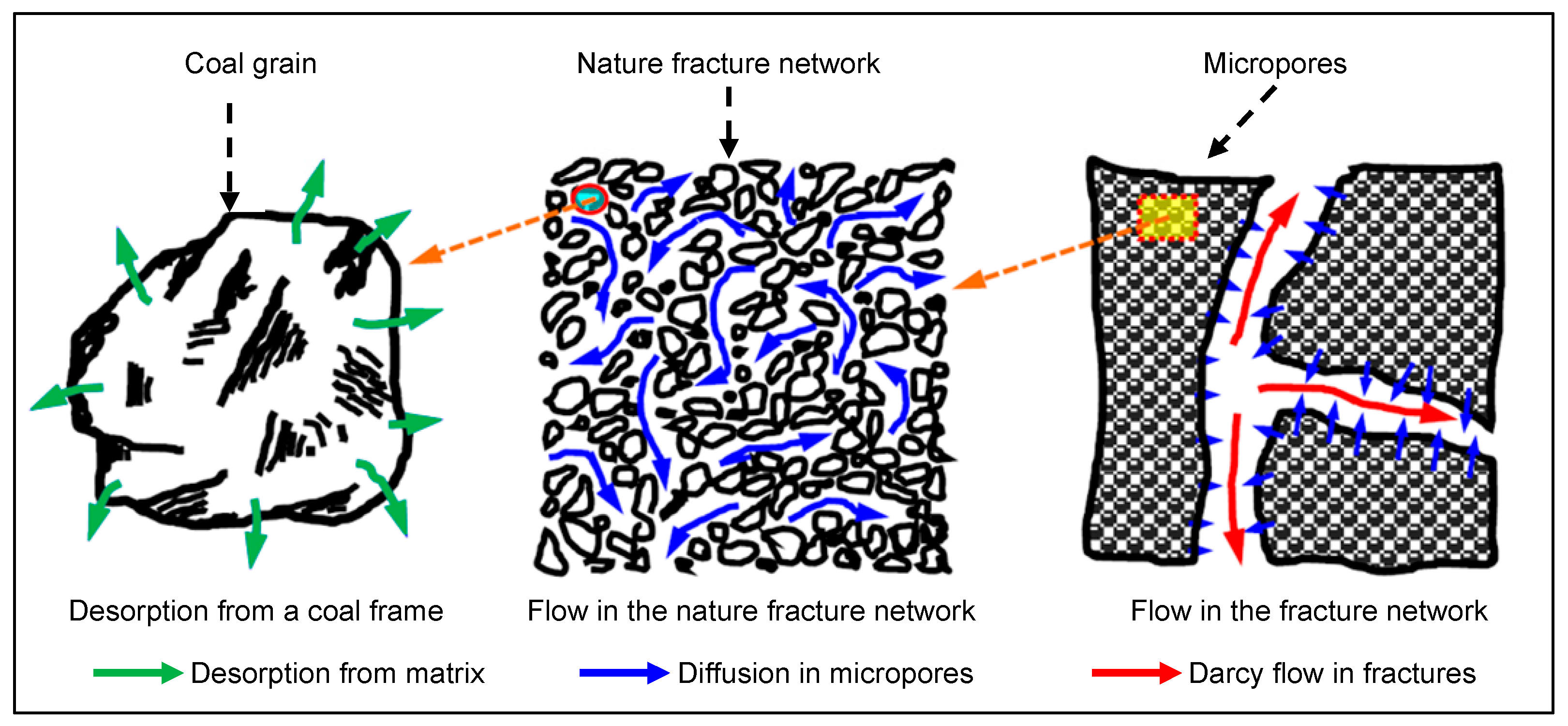
- Gas diffusion and flow occur in the matrix and cracks, respectively, and steady-state diffusion occurs (Figure 2).
- The flow in the natural fracture system is called Darcy seepage (Figure 2).
3. Mathematical Model
The adsorption and desorption processes of coal reservoirs are characterized by the Langmuir isothermal adsorption equation [31]. The equation of the material balance between the inner region and the outer region is as follows:
The infinite boundary condition is calculated as follows:
The closed boundary is as follows:
The constant pressure boundary is as follows:
When the production condition is fixed, the internal boundary condition is
The conditions for the junction between the inner zone and the outer zone are as follows:
The initial conditions are as follows:
By combining the inner and outer boundary conditions, the solution of gas pseudo-pressure under different boundary conditions can be obtained as follows (Ai-Hussainy defined pseudo-pressure in 1966 [32]):
The different parameter meanings in Equation (3) are as follows:
When the outer boundary is an infinite boundary,
When the outer boundary is a constant pressure boundary or a closed boundary,
When the outer boundary is a closed boundary,
When the outer boundary is a constant pressure boundary,
According to the Duhamel convolution principle [33], the analytical solution considering skin and the well reservoir coefficient in Laplace space is as follows:
4. Historical Fitting Analysis
In the process of solving Equation (4), Duhamel convolution and Laplace changes are involved. Duhamel convolution transforms the variable yield and variable flow pressure production into a constant yield and constant flow pressure production. The Laplace change can eliminate the time variable and reduce the equation variable. These two approaches create massive computing requirements. In the previous formula derivation, in order to improve the calculation speed, it is necessary to transform the physical problems into mathematical problems. The calculation process is dimensionless, and the internal boundary condition is the production at a fixed rate or a fixed bottom-hole flow pressure. In the actual production process, the bottom hole flow pressure and output are often changed. At this time, the process of variable flow and pressure can be realized through Duhamel convolution, and then the theoretical model can be transformed into the actual production model (Figure 3 and Figure 4). With the help of the table lookup method, dimensionless variables can quickly be quantified, which greatly reduces the calculation intensity and makes the calculation of the model reach the intensity of the software application. The principle of variational pressure production is similar to that of variational pressure production. The only difference is that in variational pressure production, since the output is unknown, it is necessary to assume an output to calculate the average pressure, and the final output needs to be calculated iteratively (Figure 4).
5. Verifying the Accuracy of the Calculation Results
In order to verify the accuracy of the results, the results were compared with those in the classical literature of Anbarci [34,35]. The Anbarci model is used for a homogeneous gas reservoir without considering the reservoir pollution. In order to make a comparison with the model of Anbarci, the model in this paper needs to be degraded. In this model, the permeability ratio of the inner zone to the outer zone is 1, the reservoir coefficient of the wellbore is zero and the skin factor of the wellbore is zero; thus, it can be degraded to the Anbarci model. The calculation parameters are shown in Table 1. For the convenience of comparison, they are converted into British units in Anbarci’s article.
As can be seen from Figure 5, compared with the analytical solution in Anbarci’s paper, the analytical solution calculated in this paper has a better fitting effect with the numerical simulation solution, and the analytical solution of Anbarci is smaller than the numerical solution. This shows that the analytical solution method in this paper can better characterize the gas flow process in the reservoir, and the characterization accuracy is better. At the same time, compared with the numerical simulation method, the analytical solution method in this paper is more convenient.
6. Gas Field Application
It can be seen from the feedback of field production that the main cause of reservoir damage in the near-well area is the poor compatibility of the current drilling fluid and fracturing fluid with the reservoir, resulting in a large number of drilling fluid and fracturing fluid invading the reservoir, which results in the reservoir being polluted and the permeability being reduced. Therefore, reservoir pollution is not only caused by the reservoir itself, but it is also caused by both the reservoir and the project. The single-well data of the example comes from fractured vertical well A in the Panhe coalbed methane field in the Qinshui Basin. The Panhe Block is located in the southeast of the Qinshui Basin. It is a west-dipping monoclinal structure on the whole, and only two faults are developed in the northeast. The fold axis is nearly north–south in the plane, and the basic characteristics of the fold include a broad and slow shape, basic symmetry in the two wings and a small inclination angle. The main coal measure strata are the Shanxi Formation of the Lower Permian and the Taiyuan Formation of the Upper Carboniferous. The Shanxi Formation is a delta sedimentary system, and the stratigraphic lithology mainly includes grey and dark grey sandstone, mudstone and coal seam. The Taiyuan Formation is a coastal barrier sedimentary system. The lithology mainly includes grey sandstone, grey mudstone, limestone and coal seam. In the process of drilling and fracturing, due to weather and engineering reasons, the drilling progress was seriously affected, the drilling time was interrupted six times and the total downtime reached 58 days. This gave the drilling fluid enough time to form filter cake through filtration and contaminate the near-wellbore area. Later, the well was hydraulically fractured to form an SRV zone. Therefore, in the historical fitting process of the well A model, it is necessary to comprehensively consider the reservoir pollution near the well and the SRV region formed by late fracturing so as to accurately characterize the flow process of the reservoir fluids in the production process of well A. The geological parameters and gas reservoir parameters of well A are shown in Table 2.
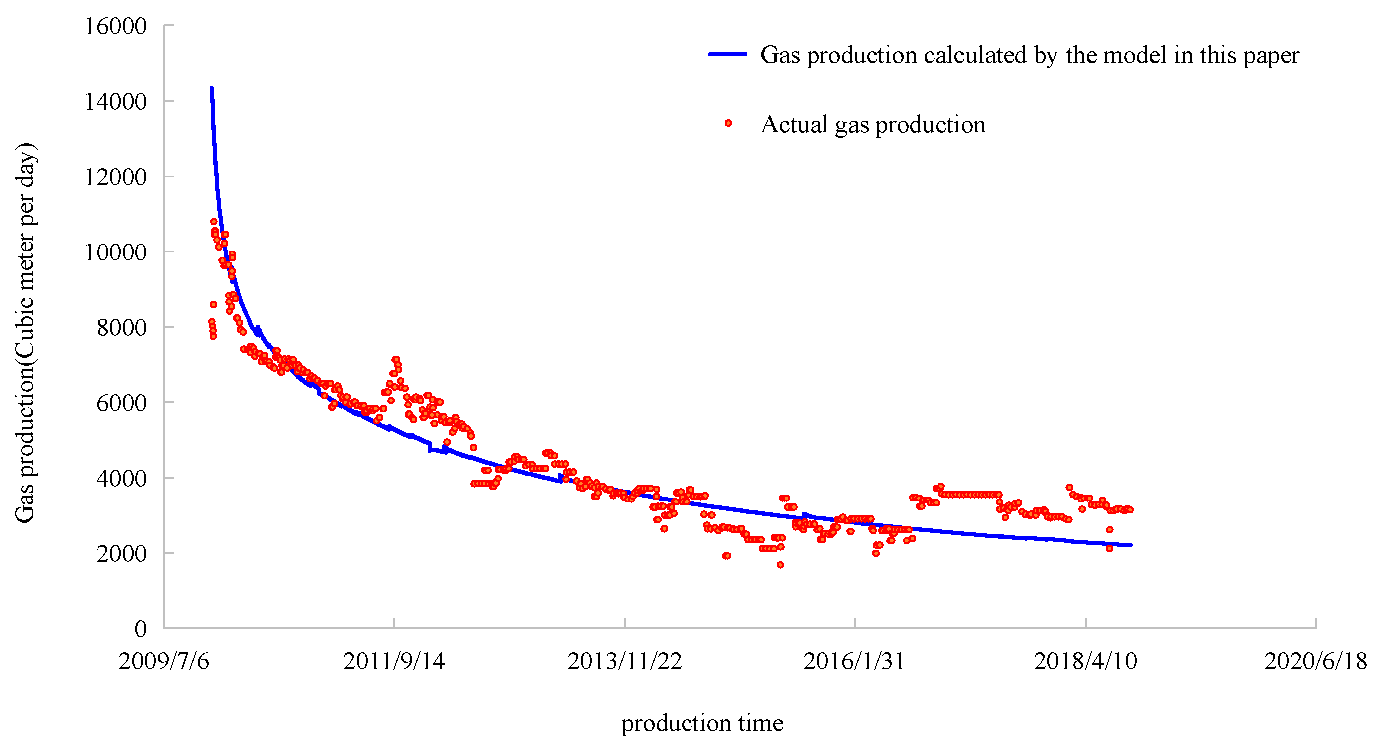
The historical fitting of the model shows a good fitting effect under the consideration of pollution near the well (Figure 6 and Figure 7). The fitting error of the single-well production is 13.42% (the fitting error is 28.9% when pollution and the SRV region are not considered), and the fitting error of the single-well cumulative gas production is 3.3% (the fitting error is 3.3% when pollution and the SRV region are not considered). The fitting error is 17.3%. The simulation results show that the permeability of the inner zone of well A is smaller than that of the outer zone. When hydraulic fracture is considered in the model, the pollution of working fluid to the reservoir is greater than the permeability increase effect formed by hydraulic fracturing in the later stage. At the same time, the main function of hydraulic fracturing is to form a flow channel with high permeability, but it cannot increase the permeability of all areas around the wellbore. Through the application of the advanced model, compared with the conventional model, the error is greatly reduced, and the yield error and cumulative production error are within the allowable error range of the project, indicating that the model has important evaluation significance for some specific CBM reservoirs and plays a guiding role in development (Table 3).
7. Result Analysis
In the process of CBM development, the productivity evaluation of a single well involves the whole production process. A single-well productivity evaluation is also an important element in block development planning and design. The productivity of coalbed methane is affected by many factors in the process of production. The typical influencing factors in this model are the original permeability of a gas reservoir, the original porosity of a gas reservoir, the ratio of inner and outer permeability, skin factor, Langmuir volume and Langmuir pressure. According to the statistics of gas reservoir parameters of most fractured vertical wells in the Panhe Block, the value range of each parameter in the sensitivity analysis is determined (Table 4). The sensitivity of the influence of each parameter on the productivity of a single well is studied by using the ten-year cumulative production as the representation index of the productivity of a gas well.
Through the simulation of the analytical solution model, the cumulative gas production under different parameters can be obtained. The cumulative gas production can be used as the basis to evaluate the productivity of a single well. Since the value range of each parameter can include the parameter variation range of the entire block, the production variation in this interval can reflect the sensitivity of the production capacity of a single well in the block to each parameter.
The most important factor affecting the cumulative production of a single well is the permeability ratio between the external and external zones, which corresponds to the pollution caused by fracturing. In the process of increasing the permeability ratio from 0.25 to 1, the gas production year increased from 3 million square meters to 7 million square meters, demonstrating a growth rate of 133%. The second is the permeability of the whole gas reservoir. In third place is the pollution caused by the wall skin factor, which is less polluting than the ratio of internal and external permeability and the permeability of the entire gas reservoir. This is because the reservoir has a relatively small influence area, and the current skin factor of 3.2 is not enough to become the bottleneck of gas production. However, compared with the Langmuir volume and Langmuir volume pressure, its influence is larger. This is because the wall is the only way for gas to enter the wellbore, and its flow environment can have a bottleneck effect on production. Changes in porosity have almost no effect on gas production because the pressure in CBM reservoirs is small and the flow environment is poor, in which case the reserves have little effect on production (Figure 8 and Figure 9).
8. Conclusions
- Compared with the classical analytical solution, the green function is more accurate in solving the fracture model and has a better fitting effect with the numerical solution. The accuracy of the result calculated by the green function is 97%, while the accuracy of the result calculated by the classical analytical solution is 89%. Please refer to the section titled Verifying the Accuracy of the Calculation Results in this article for the demonstration process.
- In the process of coalbed methane mining, the improper use of fracturing fluid and pollution caused by filtration loss in the drilling process will have a great impact on the productivity of a single well in a later stage. The pollution of working fluid in the reservoir is greater than the permeability increase effect caused by hydraulic fracturing in the later stage. The main function of hydraulic fracturing is to form a flow channel with high permeability, but it cannot increase the permeability of all areas around the wellbore. In the process of increasing the permeability ratio from 0.25 to 1, the gas production year increased from 3 million square meters to 7 million square meters, demonstrating a growth rate of 133%. Please refer to the Result Analysis Section of this article for the demonstration process.
- During the evaluation of coal bed methane productivity, the pollution caused by working fluid filtration loss and the permeability increase effect of late fracturing need to be considered. Considering the permeability difference between internal and external regions and the skin effect will greatly improve the fitting degree of the predicted value and the actual value in the productivity prediction, making the productivity prediction more accurate. As seen in the fitting data of the actual wells, the fitting error of daily gas production was reduced from 28.9% to 17.3%, and the error of cumulative gas production was reduced from 17.3% to 3.3% when considering drilling fluid pollution. The demonstration process is shown in the section titled Gas Field Application in this paper.
Author Contributions
Conceptualization, C.L. and L.S.; Methodology, C.L. and L.S.; Validation, C.L. and J.Z.; Formal analysis, Y.L., Y.M. and L.W.; Writing – original draft, C.L.; Supervision, L.S. and Z.Z.; Project administration, Z.Z. and J.Z. All authors have read and agreed to the published version of the manuscript.
Funding
This research was funded by China National Offshore Oil Corporation Limited, grant number [FCG-003] And The APC was funded by Cnooc Research Institute Limited Company.
Data Availability Statement
The original contributions presented in the study are included in the article, further inquiries can be directed to the corresponding author.
Conflicts of Interest
Authors Chen Li, Lichun Sun, Zhigang Zhao and Jian Zhang were employed by the company Research Institute Ltd. The remaining authors declare that the research was conducted in the absence of any commercial or financial relationships that could be construed as a potential conflict of interest.
Abbreviations
| Symbols in Article | |
| radial radius of gas reservoir, m | |
| pressure, MPa | |
| gas viscosity, mpa·s | |
| gas deviation factor, dimensionless | |
| porosity, decimal | |
| compressibility, MPa−1 | |
| permeability, D | |
| time variable, h | |
| reference length, L, which is equal to half of the fracture length, m | |
| pseudo-pressure, MPa2/cp | |
| temperature, K | |
| Bessel function of order 0 | |
| ratio of permeability between SRV region and outer region | |
| s | image variable of Laplace transformation |
| dimensionless wellbore storage coefficient | |
| skin factor | |
| Langmuir pressure, MPa | |
| Langmuir volume, m3/m3 | |
| gas flow rate, m3/d | |
| compressibility, MPa−1 | |
| R | external radius of matrix, m |
| D | diffusion coefficient, m3/s |
| fracture half length, m | |
| Subscripts and Superscripts | |
| D | dimensionless property |
| e | boundary property |
| g | gas property |
| L | factor of Langmuir equation |
| i | initial condition |
| sc | standard condition |
| f | fracture property |
| 1 | inner region property |
| 2 | outer region property |
| ~ | image function of Laplace transform |
| Intermediate Variables | |
| Dimensionless Variables | |
References
- Seidle, J. Principle of Coalbed Gas Reservoir Engineering; Shi, X., Ed.; Petroleum Industry Press: Beijing, China, 2016. [Google Scholar]
- Scott, A.R.; Kaiser, W.R. Hydrogeologic factor affecting dynamic open-hole cavity complections in the San Juan basin. In Proceedings of the 1995 Coalbed Methane Symposium, Tuscaloosa, AL, USA, 14–20 May 1995. [Google Scholar]
- Harrington, L.J.; Whitsitt, N.F.; Hannah, R.R. Prediction of the Location and Movement of Fluid Interfaces in a Fracture. In Proceedings of the Southwestern Petroleum Short Course, Lubbock, TX, USA, 20–23 April 1973; pp. 26–27. [Google Scholar]
- Cinco-Ley, H.; Samaniego, V.F. Transient Pressure Analysis: Finite Conductivity Fracture Versus Damaged Fracture Case. In Proceedings of the 58th Annual Fall Technical Conference and Exhibition of the Petroleum Engineers of AIME, San Antonio, TX, USA, 5–7 October 1981; Volume 10179. [Google Scholar]
- Jiao, G.; Zhao, L.; Liu, P.; Pei, P.; Lin, Y. An Analytical Model for Predicting Prudctivity of Frac and Packed Completion. Offshore Oil 2005, 25, 38–40. [Google Scholar]
- Yekeen, N.; Padmanabhan, E.; Idris, A.K. A review of recent advance in foma-based fracturing fluid application in unconventional reservoirs. J. Ind. Eng. Chem. 2018, 66, 45–71. [Google Scholar] [CrossRef]
- Ying, H.; Liu, Y.; Fu, C. Productivity analysis for fractured well in low permeability reservoir. Spec. Oil Gas Reserv. 2005, 12, 55–56. [Google Scholar]
- Len, V.; Brent, K.; Thanos, A. State of the art in coalbed methane drilling fluids. SPE Drill. Complet. 2008, 23, 250–257. [Google Scholar]
- Barr, K. A guideline to optimization drilling fluids for coalbed methane reservoirs. In Proceedings of the SPE Rocky Mountain Petroleum Technology Conference/Low-Permeability Reservoirs Symposium, Denver, CO, USA, 14–16 April 2009; Volume SPE 123175-MS. [Google Scholar]
- Zhao, J.; Guo, J. Dynamic prediction of hydraulic fracturing effects. Oil Drill. Prod. Technol. 1995, 17, 55–61. [Google Scholar]
- Gao, S.; Liu, H.; Ye, L.; Hu, Z.; Chang, J. A coupling model for gas diffusion and seepage in SRV section of shale gas reservoirs. Nat. Gas Ind. 2017, 37, 97–104. [Google Scholar] [CrossRef]
- An, Q.; Yang, F.; Yang, R.; Huang, Z.; Li, G.; Gong, L.; Yu, W. Practice and Understanding of Deep Coalbed Methane Massive Hydraulic Fracturing in Shenfu Block, Ordos Basin. J. China Coal Soc. 2024, 1, 1–18. [Google Scholar]
- Liu, Y.; Zhu, H.; Tang, H.; Sun, H.; Zhang, B.; Chen, Z. Four-dimensional in-situ stress model of CBM reservoirs based on geology-engineering integration. Nat. Gas Ind. 2022, 42, 82–92. [Google Scholar]
- Li, F.; Huang, W.; Chen, H.; Zhong, X. Coalbed methane well productivity prediction model considering pore compressibility and coal matrix shrinkage effect and influencing factors analysis of well productivity. Pet. Geol. Oilfield Dev. Daqing 2023, 42, 168–174. [Google Scholar]
- Thamas, G.; Neithan, D.; Richard, J. Effect of drilling fluids on coal permeability: Impact on horizontal wellbore stability. Int. J. Coal Geol. 2009, 78, 177–191. [Google Scholar]
- Li, H.; Cao, Y.; Zhou, D.; Cai, X.; Liu, T.; Feng, P.; Shi, B.; Tian, L. Fracturing parameters analysis and productivity evaluation of vertical coalbed methane wells with nitrogen foam. Coal Geol. Explor. 2020, 48, 65–74. [Google Scholar]
- Zhang, X.; Zhang, S.; Sun, Q.; Yang, Y.; Yang, Y. Evaluating the influence of geological structure to CBM productivity based on AHP and fuzzy mathematics. J. China Coal Soc. 2017, 42, 2385–2392. [Google Scholar]
- Reng, J. Effect of dynamic permeability variation on production of coalbed methane wells. Nat. Gas Ind. 2018, 38, 62–64. [Google Scholar]
- Sun, H.; Wang, C. Damage mechanism of cement slurry to CBM reservoirs with developed fractures and cleats: A case study from eastern Yunnan and western Guizhou in China. Nat. Gas Ind. 2018, 38, 82–87. [Google Scholar] [CrossRef]
- Zheng, L.; Li, X.; Su, G.; Zhao, W.; Gong, X.; Tao, X. Applicability of working fluid damage assessment methods for coalbed methane reservoirs. Nat. Gas Ind. 2018, 38, 28–39. [Google Scholar]
- Tian, S.; Huang, Z.; Li, G.; Lu, P.; Zhang, H.; Wang, T. Laboratory experiments on blockage removing and stimulation of CBM reservoirs by composite pulsating fracturing of radial horizontal wells. Nat. Gas Ind. 2018, 38, 88–94. [Google Scholar] [CrossRef]
- Ji, C.; Hao, C.; Xin, K.; Yu, Z.; Chang, H.; Yang, C. Study on cementing damage mechanism for reservoir of CBM well. Coal Eng. 2017, 49, 116–119. [Google Scholar]
- Wang, W.; Xiao, N.; Huang, L.; Zou, L.; Tian, Z.; Yang, H. Damage in coal reservoir caused by coal swelling after drilling fluid invasion. Drill. Fluid Complet. Fluid 2010, 27, 20–22. [Google Scholar]
- Cai, J.; Yuan, Y.; Wang, J.; Li, X.; Cao, W. Experimental research on decreasing coalbed methane formation damage using micro-foam mud stabilized by nanoparticles. J. China Coal Soc. 2013, 38, 1640–1645. [Google Scholar]
- Wang, D.; Shi, Y.; Wu, X.; Wu, C. Experimental research on decreasing coalbed methane formation damage by using low density cement slurry. Coal Geol. Explor. 2015, 43, 105–109. [Google Scholar]
- Zheng, L.; Meng, S.; Cao, Y.; Li, Z. Laboratory studies on control coalbed methane formation damage by fuzzy-ball based drilling fluids. J. China Coal Soc. 2010, 35, 439–442. [Google Scholar]
- Wang, W.; Tao, S.; Huang, L.; Zou, L.; Tian, Z.; Yang, H. Experimental research on the scaling damage in coalbed methane reservoir caused by drilling fluid. Oil Drill. Prod. Technol. 2010, 32, 35–38. [Google Scholar]
- Tao, T.; Lin, X.; Fang, X.; Cao, C.; Zhang, T. Fracturing Damage Mechanism and Fracturing Fluid with Low Damage of Coalbed Methane Well. J. Chongqing Univ. Sci. Technol. (Nat. Sci. Ed.) 2011, 13, 21–23. [Google Scholar]
- Chen, J. Reservoir damage-problems that should be paid attention to in CBM drilling. Coal Technol. 1998, 2, 18–19. [Google Scholar]
- Wei, Y.; Li, C.; Cao, D.; Cui, B.; Xiang, X. Effect of pulverized coal dispersant on coal in the CBM well-washing technology. J. China Coal Soc. 2018, 43, 1951–1958. [Google Scholar]
- Langmuir, I. The constitution and fundamental properties of solids and liquids. J. Am. Chem. Soc. 1916, 38, 2221–2295. [Google Scholar] [CrossRef]
- AI-Hussainy, R.; Ramey, H.J.; Crawford, P.B. The flow of real gas through porous media. J. Pet. Technol. 1966, 18, 625–636. [Google Scholar]
- Everdingen, V.; Hust, A.F. The Application of the Laplace Transformation to Flow Problems in Reservoirs. J. Pet. Technol. 1949, 1, 305–324. [Google Scholar] [CrossRef]
- Anbarci, K.; Ertekin, T. A comprehensive study of pressure transient analysis with sorption phenomena for single-phase gas flow in coal seams. In Proceedings of the SPE Annual Technical Conference and Exhibition, New Orleans, LA, USA, 23–26 September 1990; Volume SPE-20568-MS. [Google Scholar]
- Anbarci, K.; Ertekin, T. Pressure transient behavior of fractured wells in coalbed reservoirs. In Proceedings of the Annual Technical Conference and Exhibition, Washington, DC, USA, 4–7 October 1992; Volume SPE-24703-MS. [Google Scholar]
Figure 1.
Working fluid contamination and SRV zone models.

Figure 2.
Desorption diffusion and Darcy flow in physical models.

Figure 3.
The Duhamel convolution is used to obtain the pressure value.

Figure 4.
The Duhamel convolution is used to obtain the production rate.

Figure 5.
The analytical solution in this paper is compared with Anbarci’s analytical solution and the corresponding numerical simulation solution.
Figure 5.
The analytical solution in this paper is compared with Anbarci’s analytical solution and the corresponding numerical simulation solution.

Figure 6.
Gas production fitting of well A.

Figure 7.
Cumulative gas production fitting of well A.

Figure 8.
Cumulative gas production per well in ten years under influence of different parameters.

Figure 9.
The difference in cumulative gas production in ten years under the influence of different parameters.
Figure 9.
The difference in cumulative gas production in ten years under the influence of different parameters.


Table 1.
Basic parameters of verification model.
| τ/h | μ/cp | T/R | qsc/MMscf·d−1 | pic/psi | φ |
|---|---|---|---|---|---|
| 328,990 | 0.01082 | 530 | 0.2 | 447.7 | 0.01 |
| rw/ft | c/psia−1 | z | VL/scf·ft−3 | k/md | h/ft |
| 0.5 | 0.002234 | 0.94 | 18.6 | 26 | 6 |
Table 2.
Basic data of well A.
| Pic/MPa | s | k/md | ρg/g·m−3 | re/m | Cf/e−6kp−1 |
|---|---|---|---|---|---|
| 3.1 | 0.4 | 0.88 | 1.47 | 400 | 5 |
| h/m | M12 | φ | VL/cm3·g−1 | Lf/m | PL/Mpa |
| 4.5 | 6 | 0.02 | 60 | 90 | 1.4 |
Table 3.
Fitting error between gas production and cumulative gas production in well A.
| Inner Permeability (mD) | Outer Permeability (mD) | Ratio of Outer to Inner Permeability | Simulation | Daily Gas Volume Fitting Error | Cumulative Gas Production Fitting Error |
|---|---|---|---|---|---|
| 0.88 | 0.88 | M12 = 1 | A * | 28.9% | 17.3% |
| 1.76 | 0.88 | M12 = 0.5 | B * | 23.5% | 13.1% |
| 0.44 | 0.88 | M12 = 2 | 21.5% | 11.6% | |
| 0.15 | 0.88 | M12 = 6 | 17.3% | 3.3% | |
| 0.09 | 0.88 | M12 = 10 | 20.7% | 12.3% |
A * indicates that near-wellbore permeability changes are not considered; B * indicates that near-wellbore permeability changes are considered.
Table 4.
Distribution of sensitivity parameters in Panhe Block (3# coal).
| Parameters | Basic | Max | Min | Step Size |
|---|---|---|---|---|
| k (mD) | 0.6 | 1 | 0.2 | 0.2 |
| φ (%) | 2 | 3 | 1 | 0.5 |
| M12 | 1/3 | 1 | 1/5 | |
| SK | 0 | 3.2 | 0 | 0.8 |
| VL (m3/ton) | 60 | 70 | 50 | 5 |
| PL (Mpa) | 1.3 | 1.5 | 1.1 | 0.1 |
Disclaimer/Publisher’s Note: The statements, opinions and data contained in all publications are solely those of the individual author(s) and contributor(s) and not of MDPI and/or the editor(s). MDPI and/or the editor(s) disclaim responsibility for any injury to people or property resulting from any ideas, methods, instructions or products referred to in the content. |
© 2024 by the authors. Licensee MDPI, Basel, Switzerland. This article is an open access article distributed under the terms and conditions of the Creative Commons Attribution (CC BY) license (https://creativecommons.org/licenses/by/4.0/).
Share and Cite
MDPI and ACS Style
Li, C.; Sun, L.; Zhao, Z.; Zhang, J.; Li, Y.; Meng, Y.; Wang, L. A Method for Evaluating Coalbed Methane Reservoir Productivity Considering Drilling Fluid Damage. Energies 2024, 17, 1686. https://doi.org/10.3390/en17071686
AMA Style
Li C, Sun L, Zhao Z, Zhang J, Li Y, Meng Y, Wang L. A Method for Evaluating Coalbed Methane Reservoir Productivity Considering Drilling Fluid Damage. Energies. 2024; 17(7):1686. https://doi.org/10.3390/en17071686
Chicago/Turabian StyleLi, Chen, Lichun Sun, Zhigang Zhao, Jian Zhang, Yong Li, Yanjun Meng, and Lei Wang. 2024. "A Method for Evaluating Coalbed Methane Reservoir Productivity Considering Drilling Fluid Damage" Energies 17, no. 7: 1686. https://doi.org/10.3390/en17071686
Note that from the first issue of 2016, this journal uses article numbers instead of page numbers. See further details here.