Article

Numerical Study on the Characteristics and Control Method of Coal Leakage between Supports in Integrated Mining of Extremely Loose and Soft Coal Seams

School of Mines, China University of Mining and Technology, Xuzhou 221000, China
*
Author to whom correspondence should be addressed.
Energies 2024, 17(5), 1013; https://doi.org/10.3390/en17051013
Submission received: 30 January 2024 / Revised: 12 February 2024 / Accepted: 19 February 2024 / Published: 21 February 2024

Abstract

:
Extremely loose and soft coal seams, with a Platts coefficient of less than 0.3, are easy to break in the process of integrated mechanized roof coal mining and are prone to spilling and piling up between the hydraulic supports, which is a safety hazard for the movement of equipment. The coal particles must be cleaned up manually, resulting in reduced resource recovery rates and lower mining face efficiency. To effectively mitigate and control the problem of coal spillage accumulation amidst hydraulic supports, this study utilizes discrete element numerical simulation to examine the characteristics of block size distribution and the spilling process during the crushing of highly loose and soft top coal. By taking into account various parameters associated with shelf spacing, this research identifies key factors for controlling arching and self-stopping phenomena in top coal particles. The study findings suggest that the uppermost coal layer undergoes significant fragmentation during the integrated mining process of loosely packed and soft coal seams, resulting in a higher probability of coal leakage issues observed near the rack’s coal wall side and at the end of the roof control area. The key factors contributing to the self-arresting of spilled coal particles include inherent characteristics of the coal body, particle diameter, and stand spacing. In this specific mine under investigation, an arch formation naturally occurs to prevent further leakage when the distance between stands is less than eight times the diameter of particles, and after process correction, the average time saving for a single shift of manual floating coal cleaning at the working face is about 2 h, and the proportion of time saving is more than 50~75%.

1. Introduction

The longwall top coal caving mining technology (LTCC) has demonstrated its high efficacy as a mining method, offering robust support for addressing the challenges of coal extraction in complex conditions characterized by significant variations in thickness, one-time full-height extraction, intricate roof slab structures, and horizontally segmented sharply inclined coal seams [1,2,3,4]. In comparison to other methods, such as large-height mining and stratified mining, LTCC presents numerous advantages, including low investment requirements, rapid production rates, cost-effectiveness, energy efficiency, minimal emissions, and exceptional adaptability [5,6,7,8]. Consequently, it has emerged as an innovative mining technology within the global coal industry.
The integrated mechanized roof coal mining technology system has garnered significant attention from researchers and has undergone continuous refinement [9,10]. Specifically, the integrated mechanized roof coal mining technology for special geological conditions has demonstrated unparalleled superiority in terms of productivity and efficiency [11]. Successive breakthroughs have been achieved in comprehensive mechanized roof coal mining technology for complex mining conditions such as “Soft roof seams, soft main mining coal seams, and soft coal seam basement seams” coal seams [12,13,14], thick coal seams with hard roofs [15], and high gas mines, enabling better adaptation to the respective mines’ geological conditions.
The discrete element numerical simulation method was introduced in the research process of integrated mining at the beginning of this century. In comparison to other methods, such as large-height mining and stratified mining, LTCC presents numerous advantages, including low investment requirements, rapid production rates, cost-effectiveness, energy efficiency, minimal emissions, and exceptional adaptability. Consequently, it has become a crucial approach for comprehensive release mining research.
Among these studies, Wang Jiachen et al. systematically investigated the release law of top coal in comprehensive release mining using a self-developed similar simulation experimental bench and discrete element simulation software, thereby establishing the BBR research system [16]. Zhang Ningbo et al. employed discrete element simulation software to analyze how different thicknesses of top coal influence both the characteristics of coal gangue flow fields and top coal discharge laws [8,17]. Their findings indicated that the loss in top coal gradually accumulates with each cycle of coal discharge, while also revealing that velocity fields and contact force fields within the flow pattern exhibit a half-arch shape centered around the opening for coal discharge. Du Longfei et al. conducted discrete element simulations and theoretical analyses on multi-port coal release technology [18,19], which led them to summarize an annular release process for top coals based on morphological characteristic stages; they also provided a functional relationship equation between the development width and number of ports used for releasing coals.
The term “extremely loose and soft coal seam” refers to a specific classification of coal seams with a Platts firmness coefficient of less than 0.3 [20,21], which are extensively distributed in the western part of Henan Province and the northern part of Anhui Province in China. When employing integrated mechanized roof coal mining technology to extract these extremely loose and soft coal seams, they tend to easily fracture, leading to significant spillage within the hydraulic support gaps at the working face. This poses safety hazards such as conveyor upward movement and hydraulic support tilting, necessitating substantial manpower and material resources for cleaning up the floating coal. Consequently, it severely impacts normal construction efficiency at the mining face while also reducing resource recovery rates.
The studies on the relationship between top coal and hydraulic support in the roof control area are relatively focused on the process of top coal releasing at the back of the support: Krzysztof Skrzypkowski et al. used the bearing capacity index “g” to evaluate the cooperation between the top of the support and the rock body to determine whether the conditions for maintaining excavation are stable [22]; Zeng Qingliang et al., based on the dynamic coupling numerical model of hydraulic support and top coal, determined the main influencing factors of hydraulic support working resistance, including fracture location, force and gangue distribution [23]. The problem of coal leakage between hydraulic supports has been raised in the research of comprehensive mining of extremely soft coal seam. However, due to the small size of the crushed coal, the number of analyzing units involved in the simulation of coal leakage between hydraulic supports in extremely soft coal beds becomes huge and the structure is very complicated. The coal leakage problem itself is small in engineering scale and small in technical application scope, so this kind of problem has not been emphasized.
Although previous research on integrated mining of loose coal seams has raised this issue [21,24], there is a lack of targeted investigation into inter-shelf coal leakage problems along with inadequate applicability provided by reference technologies.
The present study aims to investigate and discuss the issue of coal leakage between hydraulic supports through discrete element numerical simulation while considering the geological conditions of extremely loose and soft coal seams in Chaochuan Coal Mine, Henan Province. Specifically, this research focuses on analyzing the generation and distribution characteristics of fissures and lumps. It also aims to understand the governing law for spillage flow during the crushing process of top coal under extremely loose and soft conditions. Furthermore, it seeks to identify key influencing factors for controlling spillage to provide a theoretical basis and engineering program that can be referenced when addressing related challenges.

2. Numerical Modeling of Coal Leakage between Hydraulic Supports

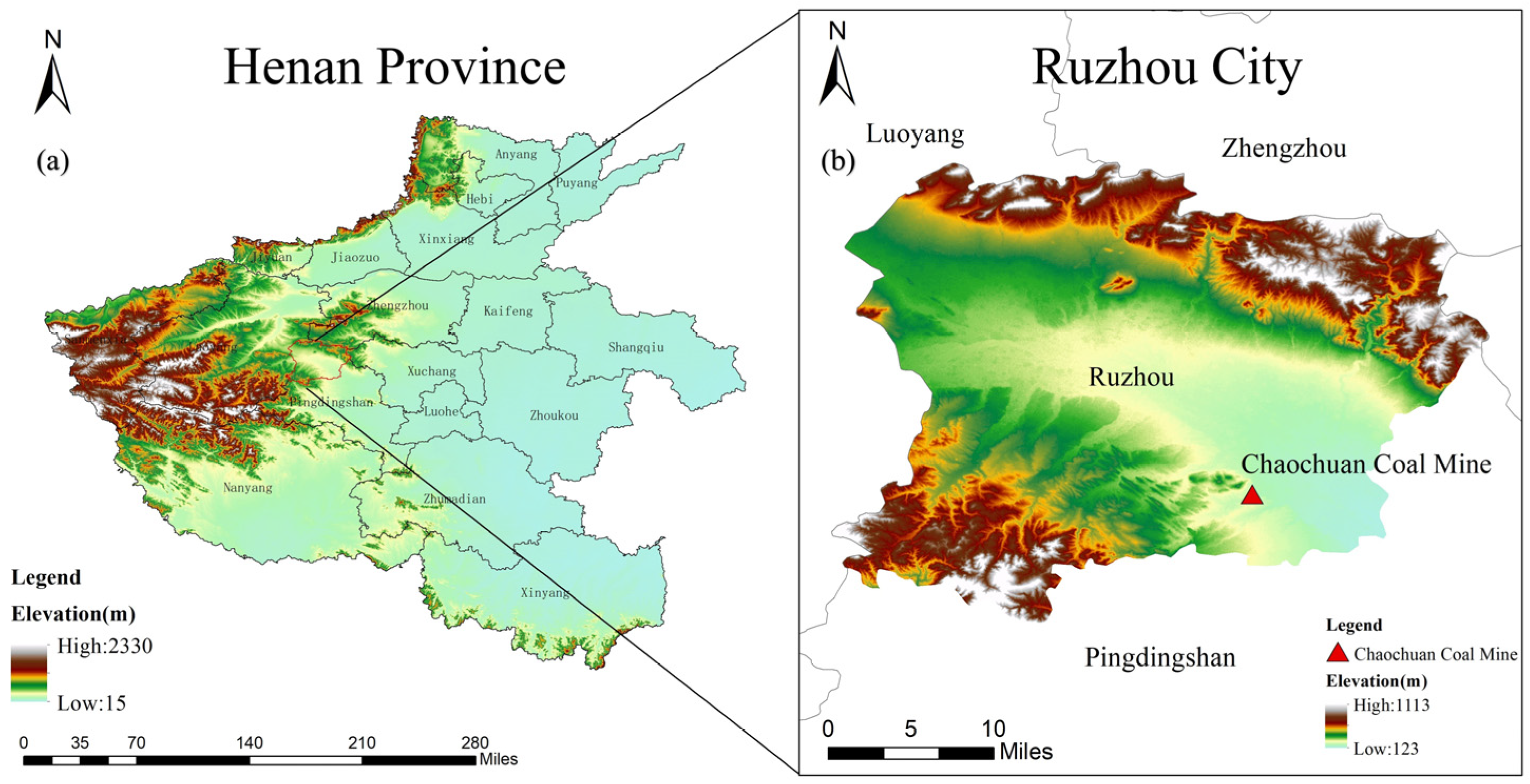
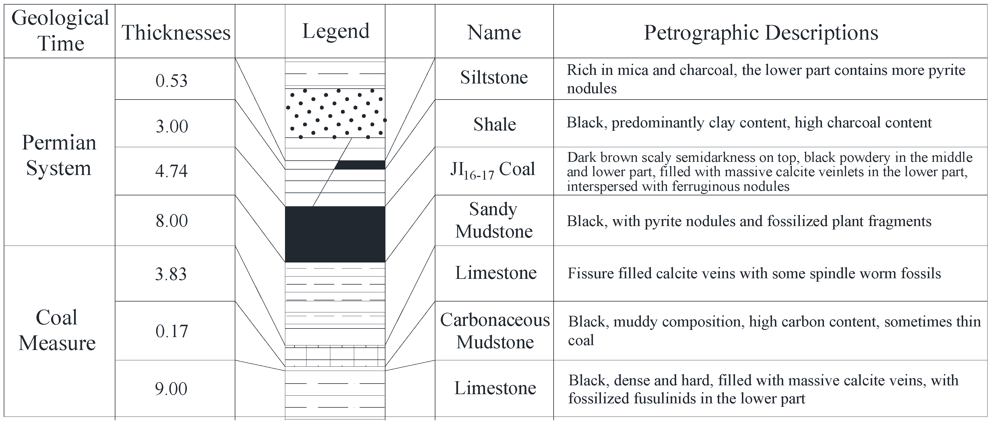
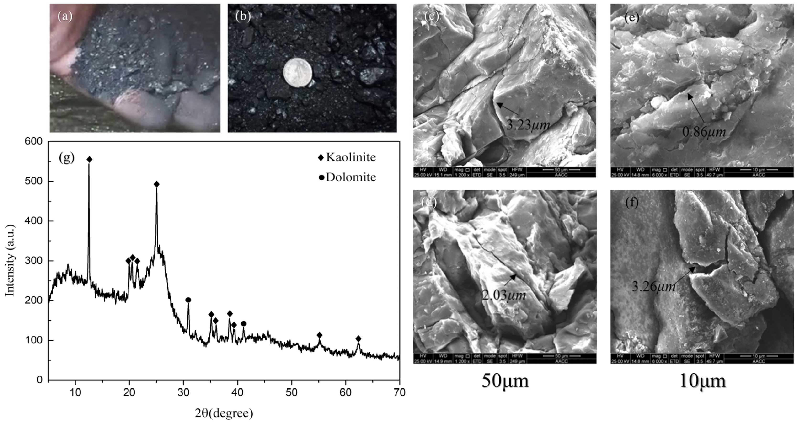
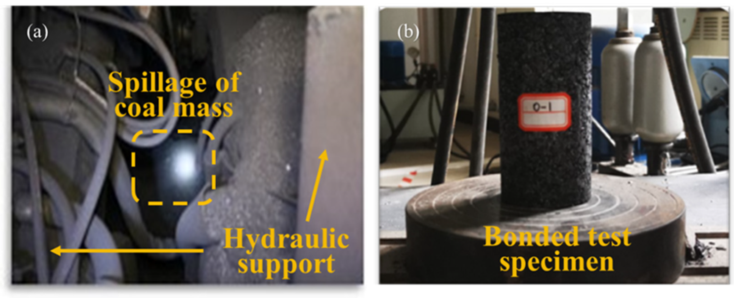
2.1. Geological Conditions of Study Mines

Chaochuan Mine is located in Xiaotun Town, Ruzhou City, Henan Province [Figure 1], and consists of three pairs of mines, namely, the first, second, and third wells. The mine area is 16.3407 km2, with underground mining as the standard mining form, elevation of +144 m to −580 m, and a production scale of 810,000 t/a.
Chaochuan Mine is a low-gas mine and has no impact tendency. The comprehensive geology is shown in the figure below Figure 2.
The study coal samples were collected from the JI 16-17-21180 working face. The JI 16-17-21180 working face adopts the longwall backward integrated mechanical roof coal mining method, and integrated mechanical roof coal mining process, and adopts all the straddle-fall methods to deal with the mining airspace. During the mining process, there are a lot of dust particles in the air at the working face, a large number of coal particles leaking between the hydraulic supports, and a large number of coal particles leaking out of the back of the hydraulic supports to the outside of the scraper conveyor. The accumulation of the particles caused the scraper conveyor to be elevated when moving, and the hydraulic support also had difficulties in moving the frame. At present, the working face uses manual cleaning to dispose of the spilled coal particles, which is inefficient and takes up 1/2 of the time of a single operation cycle.
The coal seam thickness of the “JI 16-17” coal bed in Chaochuan mine ranges from 0 m to 12.3 m, with an average thickness of 4.3 m. This particular coal bed exhibits significant variability in its thickness and possesses remarkably loose characteristics. For the operation at working face 21180, the synthesized placing process utilizes ZFY6800/18/35 cover-type roof coal placing hydraulic support, which is specifically designed for this purpose. It should be noted that the coal bed thickness varies between 3.2 m and 4.5 m in this specific area.
The direct top is dominated by sandy mudstone with an average thickness of 4.5 m, and the basic top is medium–coarse-grained sandstone with a thickness of about 7 m. The direct bottom is sandy mudstone with a thickness of about 5.6 m, and the basic bottom is chert with a thickness of about 4.9 m.
The coal block sample obtained from the working face was examined using an electron microscope. It can be seen that there are a large number of longitudinal and transverse fissures on the surface of the coal body, and the fissure scale is small. Figure 3c,d show the fissure characteristics of the top coal particles under 1000 magnification; the fissure size is 2–3 μm. The presence of nanoscale cracks (860 nm) on the surface of the coal body can be seen in Figure 3e after increasing the magnification and changing the shooting angle, which is enough to see that the integrity of the coal body is extremely poor, and it is extremely broken in the process of mining.
This observation suggests that significant crushing occurred during the mining process. X-ray diffraction analysis of the samples demonstrated that carbon constituted 91.8% of the composition, clay minerals accounted for 7.5%, and alkaline calcium carbonate comprised 0.7%. Among these clay minerals, kaolin represented 70.3%, while dolomite made up 29.7% [Figure 3g].
There are a large number of clay minerals in the coal body, which are mainly composed of kaolin and alkali calcium carbonate, both of which are silica-aluminate, with lamellar crystal shapes, and the layers are connected by hydrogen bonding or van der Waals’ forces between -Si-O-Al-O. In the absence of water (dry), the distance between the layers is very small (about 1 micron), while in the presence of water, a large amount of water can be adsorbed between the layers to form “hydrated clay”, which has flocculating properties compared to dry clay. Clay minerals account for a large proportion of the total amount of coal samples, so the injection of water helps to agglomerate the loose coal body and reduce the coal body sliding and spilling [25].

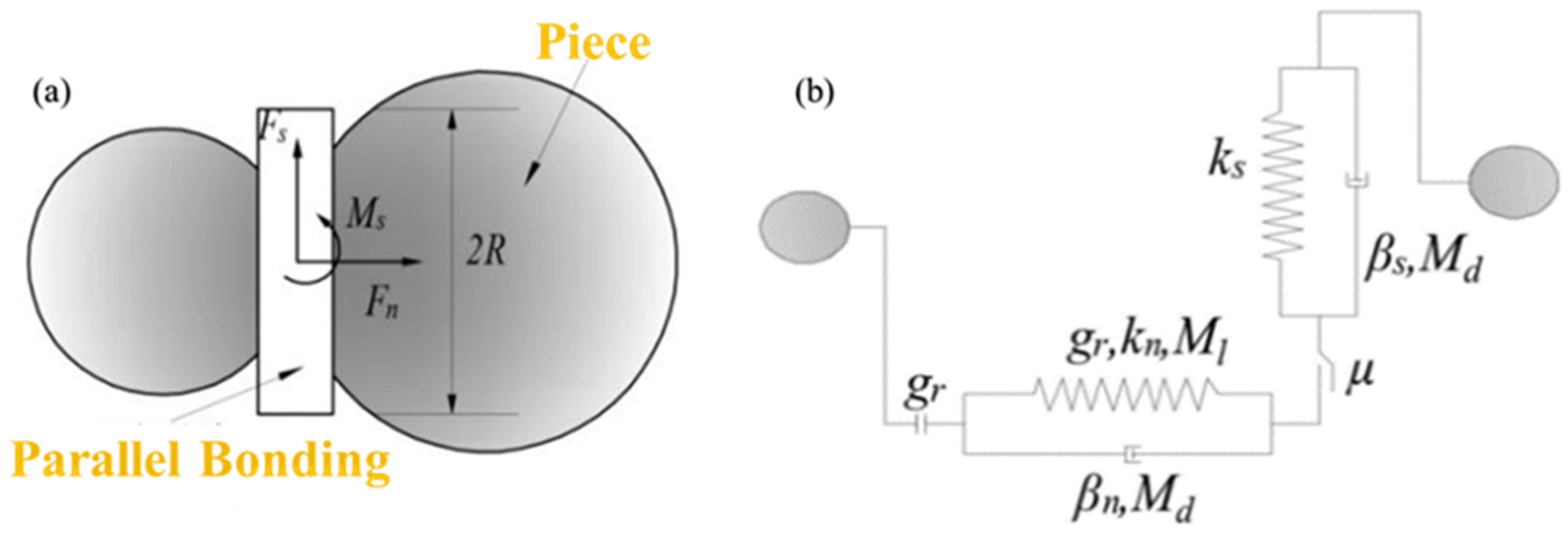
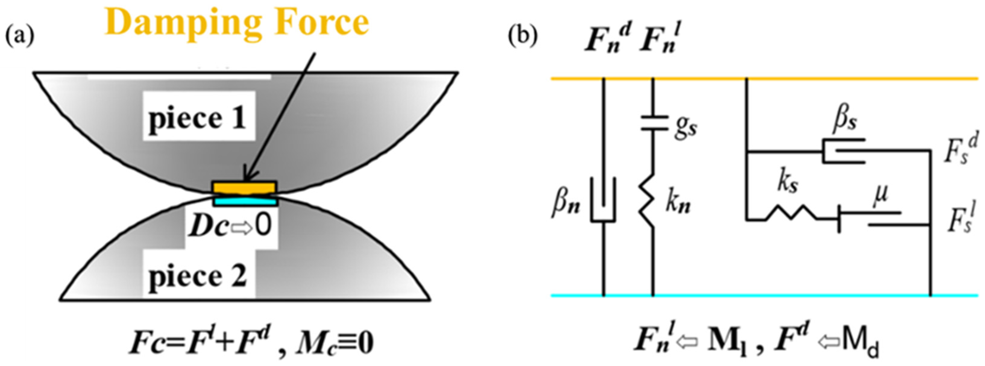
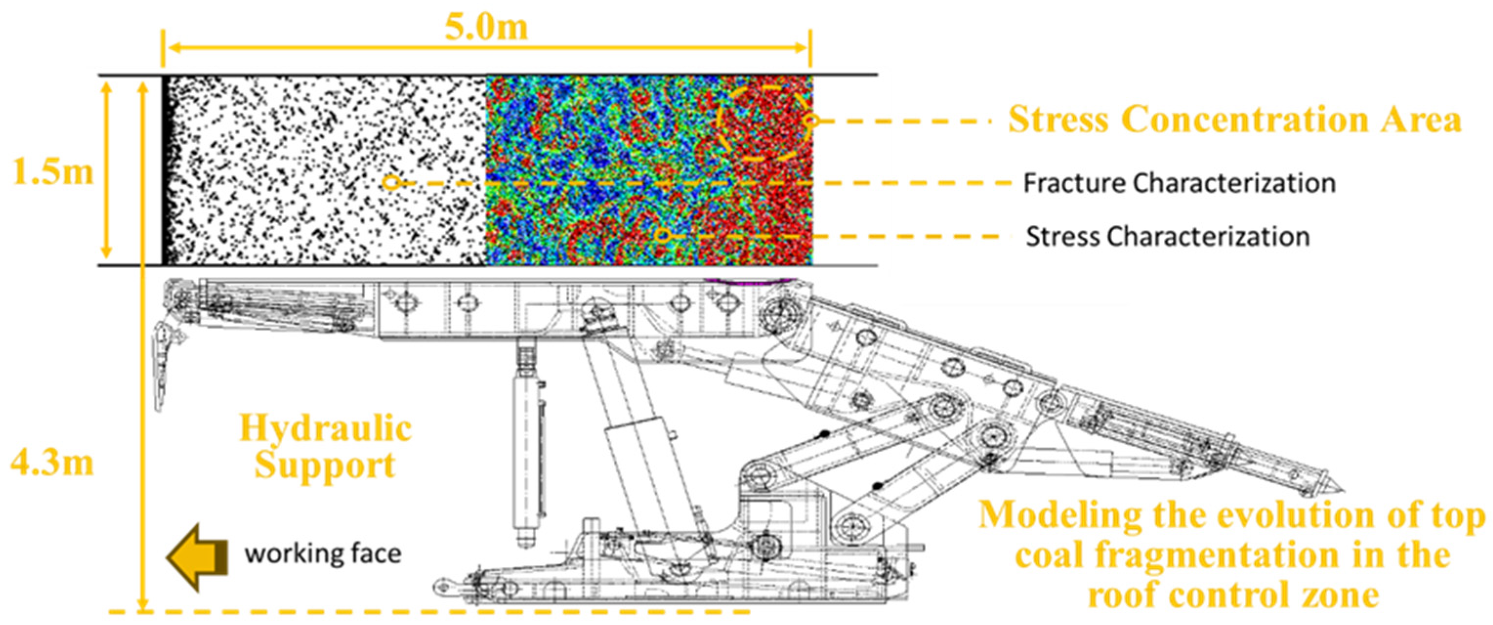
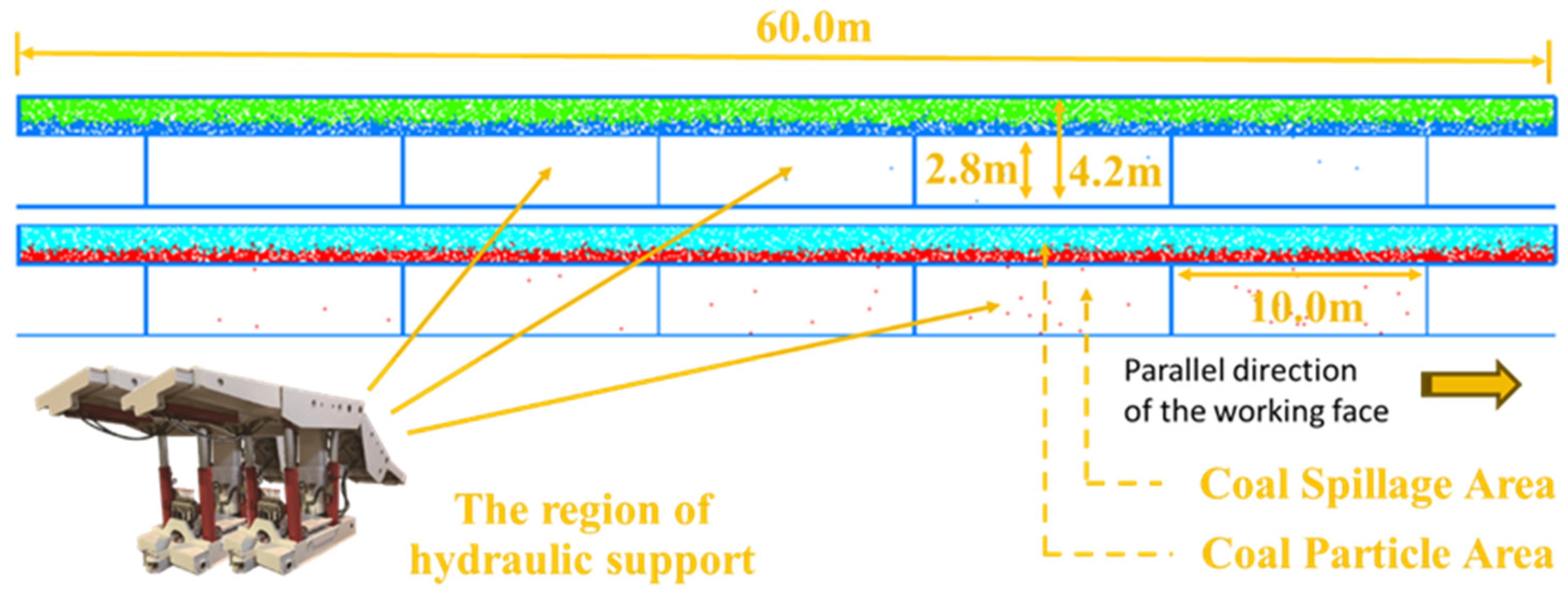
2.2. Development of Numerical Models

This study is based on two models, namely the evolutionary model of top coal crushing in the roof control area and the model of coal particle spillage between hydraulic supports. The evolutionary model of top coal crushing in the roof control area is utilized to investigate the patterns of top coal fragmentation in this specific region, identify vulnerable points for coal leakage, and provide guidance for preventing and controlling particle leakage. Meanwhile, the model examines how key factors such as support gap width, size of coal and rock particles, and friction articulation ability influence leakage, while identifying factors that contribute to arch formation between shelves and self-supporting behavior during coal leakage.
The model is established using the discrete element numerical simulation software PFC in conjunction with the research findings of He Xin et al. [15,26].
The parallel bonding model is one of the bonding models built into the software, the core implementation of which is to generate a bonding material of a certain size between neighboring particles. When the bonding material is broken, the broken surface of the particles will become a linear stiffness model. In this model, the particles can be similar to springs with constant normal and tangential stiffness, uniformly distributed in a rectangular cross-section on the contact plane centered at the point of contact. These springs act in parallel with the springs of the linear assembly to produce a parallel bond, and then contact occurs where the bond breaks if the maximum stress exceeds the bond strength. It is possible to model the contact forces F ¯ p and moment M ¯ p expressed as:
F ¯ p = F n n ¯ p + F s t ¯ p
M ¯ p = M n n ¯ p + M s t ¯ p
In models made using the parallel bonding ontological relationship, a large number of particles are usually bonded to form constructs of multiple shapes, while the mechanical properties of the constructs are described using the holistic approach. The fact that the constructs are composed of multiple particles also allows the constructs to be modeled with tensile, shear, and torsional mechanical characteristics. When the stress on the construct exceeds its corresponding bond strength, the bond relationship between particles will be broken, the bond relationship at the corresponding particle contact will be degraded to a linear relationship, and the construct as a whole becomes multiple smaller constructs that continue to move, as shown in Figure 4.
In contrast, a linear model is usually a collection of numerous bulk particles, as shown in [Figure 5], and such models are generally used to explore the simulation of leakage effects of multiple particles. The contact force of the model mainly consists of a linear part, which includes linear and frictional forces, and a damping part, which mainly provides a viscous blocking effect. The contact force Fc of the model can be expressed as:
F c = F l + F d
M c ¯ 0
which includes the linear contact force, damping force, and torque, which the linear model cannot generate. Only regular and tangential forces exist between particles.
In the linear model, the particles will only be in point contact and can only transfer friction to each other. In the parallel bonding model, there is a bond between the particles that can transfer force and moment; bonding bond destruction still exists, similar to the linear model of the point contact state; this feature is usually utilized in the simulation of the characteristics of the collapse of the stratum. The linear stiffness model is often used to simulate the flow of fluids, and the gangue’s coal gangue interface characteristics and mixing characteristics have advantages. The linear stiffness model is often advantageous in simulating the fluid flow and discharge law.
The crushing evolution process model adopts a parallel bonding ontological relationship, while the inter-shelf coal leakage model adopts a linear stiffness ontological relationship due to difficulties in sampling and fully characterizing the original coal rock body. A physical experimental calibration approach is employed for parameter selection of the numerical model. Therefore, equivalent bonded samples from spilled inter-shelf coal bodies are utilized for parameter extraction [Figure 6].
The dimensions of alternative models are determined based on both the length of the hydraulic support within the working face and the extent of the roof control area.
The working resistance of ZFY6800/18/35 cover type roof coal discharge hydraulic support used in the working face is 6800 KN, the minimum height is 1800 mm, and the maximum height is 3500 mm. When the top coal is soft, all the given deformation of the old top is absorbed by the plastic deformation of the top coal, and the direct top will be deformed off the layer under the action of gravity. Therefore, the given deformation pressure acting on the support is small or even zero; at this time, the load of the hydraulic support is mainly the weight of the top coal and the direct top. The model also provides gravity size support for the top coal in the roof control area, because the crushing speed of the extremely soft coal seam is faster, so the influence of the higher level and impact load on the crushing of the top coal in the roof control area is simplified, and the pressure of the upper roof is controlled by the way of locating the shifting speed. Model parameters are defined as follows:
The fine-scale parameters are presented in Table 1, while the model calculations terminate when the residual strength drops below 70% of its peak value.
Figure 7 illustrates that our top-coal-crushing evolution model has a length of 5 m and a height of 1.5 m. It is connected to a rigid wall adjacent to the coal wall on its left side while remaining open on its right side until the release of top coal.
The coal leakage model between the shelves consists of two layers [Figure 8], with a length of 60 m. Its design combines the actual coal seam thickness and hydraulic support height of the mine. The block section has a height of 1.5 m, while the release area has a height of 2.8 m. To simulate different wall gaps between hydraulic supports, various widths are employed to represent spilled particles with diameters ranging from 1 to 10 times that of coal bodies [27]. These gaps are evenly spaced approximately every 10 m, and partitions are implemented to facilitate convenient data collection on spilled particles.
The control model uses a time step of 1 × 10⁻⁵ s to ensure precise calculations. To improve computational efficiency and facilitate the investigation of the relationship between coal particle size and hydraulic bracket spacing, the hydraulic bracket space leakage model employs particles with similar diameters. To speed up modeling, the spilled block is divided into two layers, with larger diameter and porosity particles placed on top. Additional parameters can be found in Table 2.

3. Numerical Simulation Results and Analysis

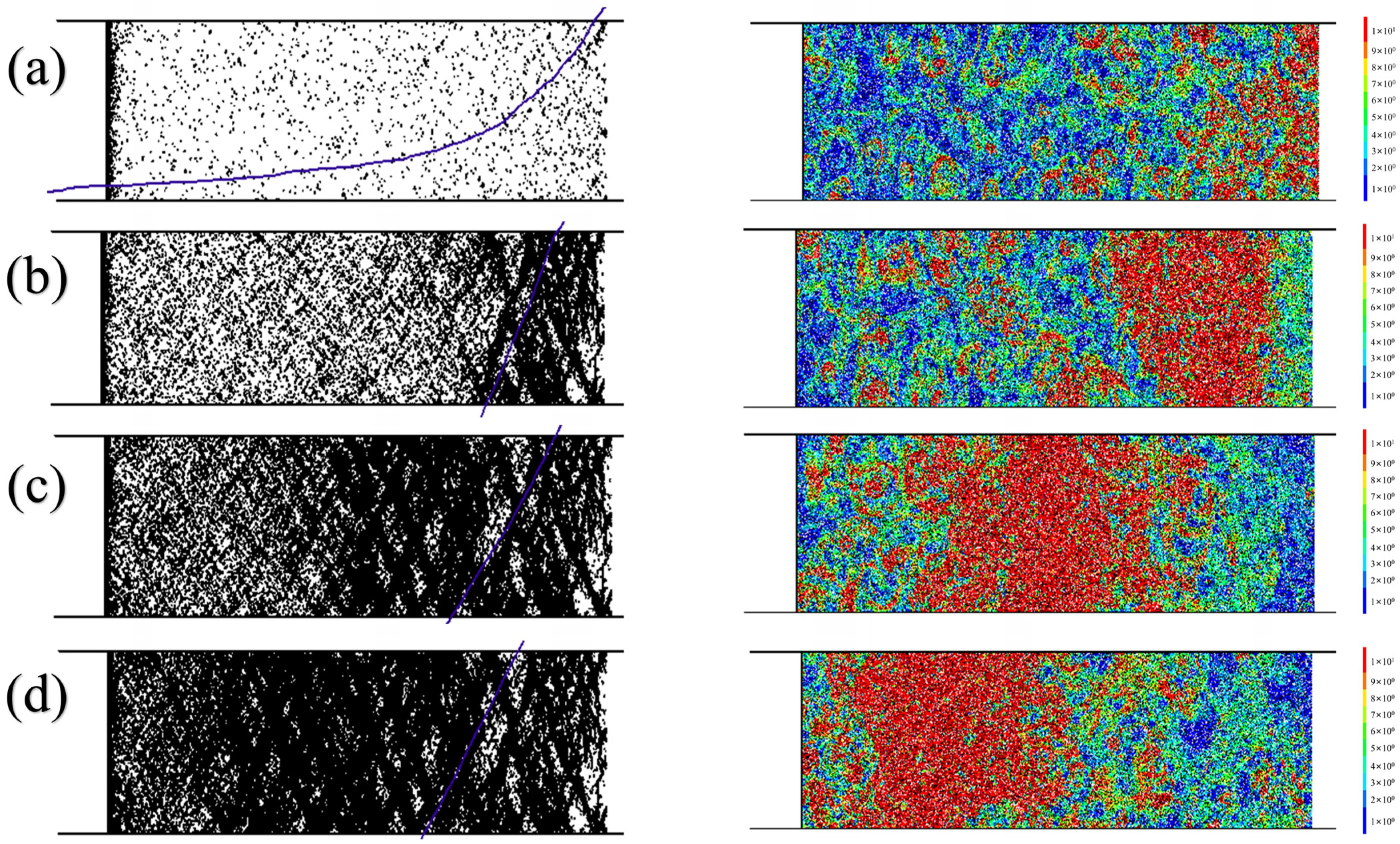
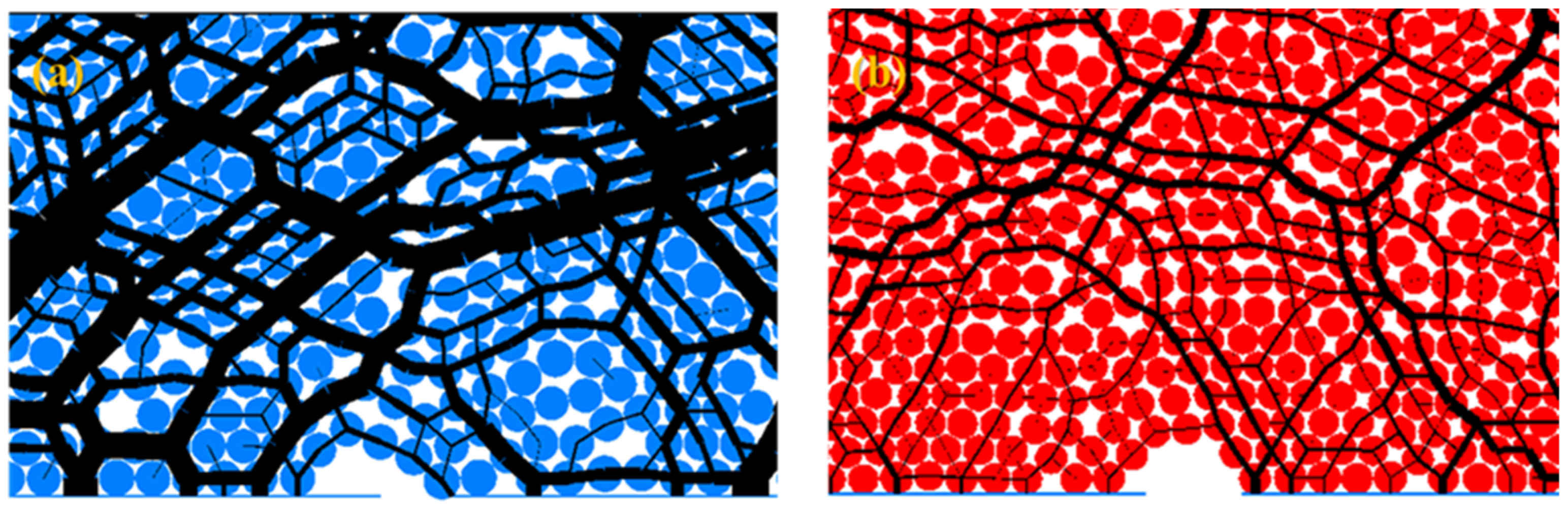
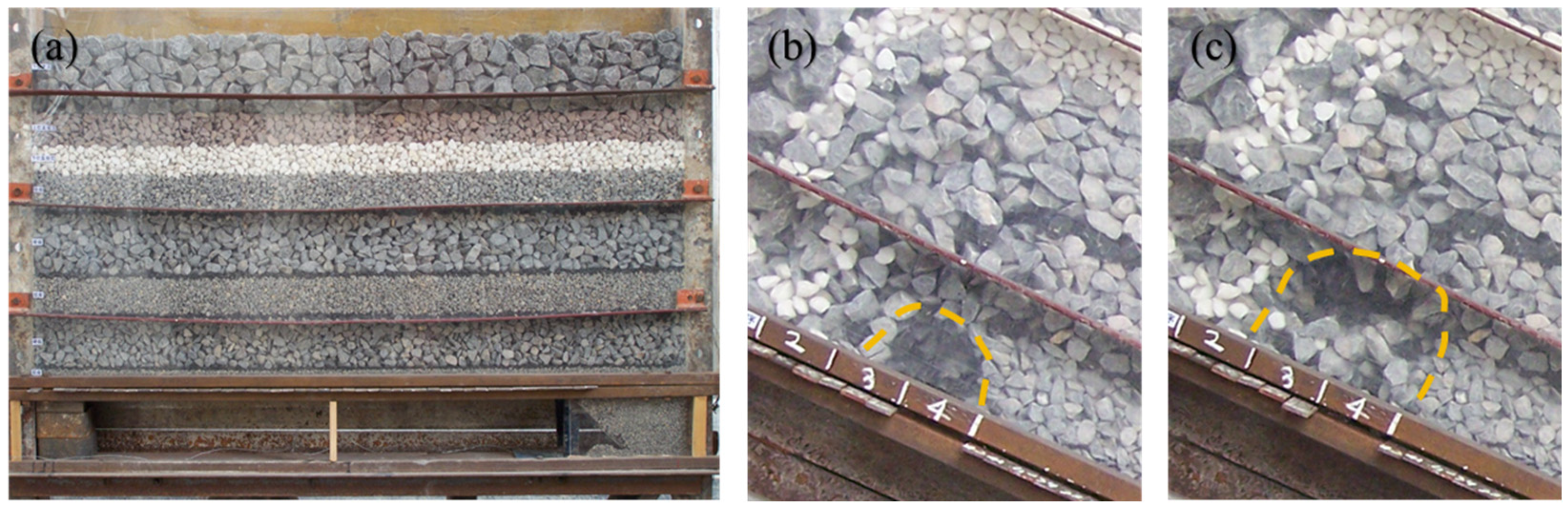
3.1. Top Coal Crushing Characteristics

The simulation process of the crushing evolution model was divided into four distinct time intervals based on their average duration. During each time interval, the number of generated fissures (DFN) and the stress distribution were quantified to reconstruct the dynamic progression of crushing.
The left side of the Figure 9 depicts a fissure in the top coal, represented by a black line segment, with the broken top coal mass enclosed within it. On the right side, different colors are employed to distinguish varying magnitudes of contact force between particles and restore stress distribution within the simulated coal body.
As can be seen from the Figure 9, according to the time course, the crushing of the top coal first concentrates on the end of the working face and the rear of the roof control area, and the generation of fissures at the end of the working face is suspended after the complete separation of the top coal from the rigid wall. The cracks in the rear part of the roof control area expand and extend to the left side, and the speed of crack generation is faster than that at the beginning. The stress concentration shows the process of transferring from the back of the roof control area to the working face direction, and it can be seen from the figure that the stress concentration area gradually expands with the change in time, and the effect of stress concentration is weakened due to the complete crushing of the top coal at the back of the roof control area after the stress area is transferred to the left side.
By observing its evolutionary process, it can be noted that crack development undergoes distinct stages of initiation, propagation, and transfer from right to left. This phenomenon is attributed to support provided by a rigid wall on the left side, resulting in predominantly compressive and shear damage on the more stressed right side of the coal body. The direction of crack penetration aligns at an angle equal to 45 + φ / 2 (where φ represents the internal friction angle). As crushing progresses continuously, significant fragmentation occurs in the right coal body, leading to a gradual reduction in bearing capacity and subsequent stress transfer towards deeper regions on its left side. Stress transfer is ahead of schedule compared to the crushing process.
The purple line in the figure represents the statistical data on fissure generation in the model [Figure 10]. It can be observed from the statistics that this process involves two distinct stages. Initially, small fissures primarily occur within the fractured region between the top coal and coal wall while maintaining the predominantly elastic behavior of the coal body. As bearing strength increases, extensive rupture of the coal body initiates from its right side and progresses towards leftward movement. Simultaneously, stress concentration shifts to preceding areas of broken coal accumulation, resulting in a linear growth pattern for fissure development.
After relocating the contact force concentration area towards the coal wall (left side), the entire model reaches its peak stress state. Subsequently, there is a gradual decrease in bearing capacity with continued loading. By time point 4 of the simulation, the residual strength of the coal body amounts to approximately 70% of its peak strength. The crushing behavior observed in the upper coal primarily exhibits characteristics such as intactness near the wall and fragmentation further away from it, while complete crushing occurs at the back.
Combined with the setup conditions of the model, the pressure of the hydraulic support roof beam on the top coal rock body is basically equal to the pressure brought by the top coal of the upper roof control area and the sinking of the roof plate, and in the expansion process of the cracks, we can see that the strength of the top coal of the roof control area decreases after reaching the maximum bearing capacity, and the expansion and generation of cracks at this time are still in a state of linear growth.
The simulation restored the crushing state of top coal before releasing it down. The crushed particles flowed toward the back of the hydraulic support and gradually moved to the coal release opening to be recovered.

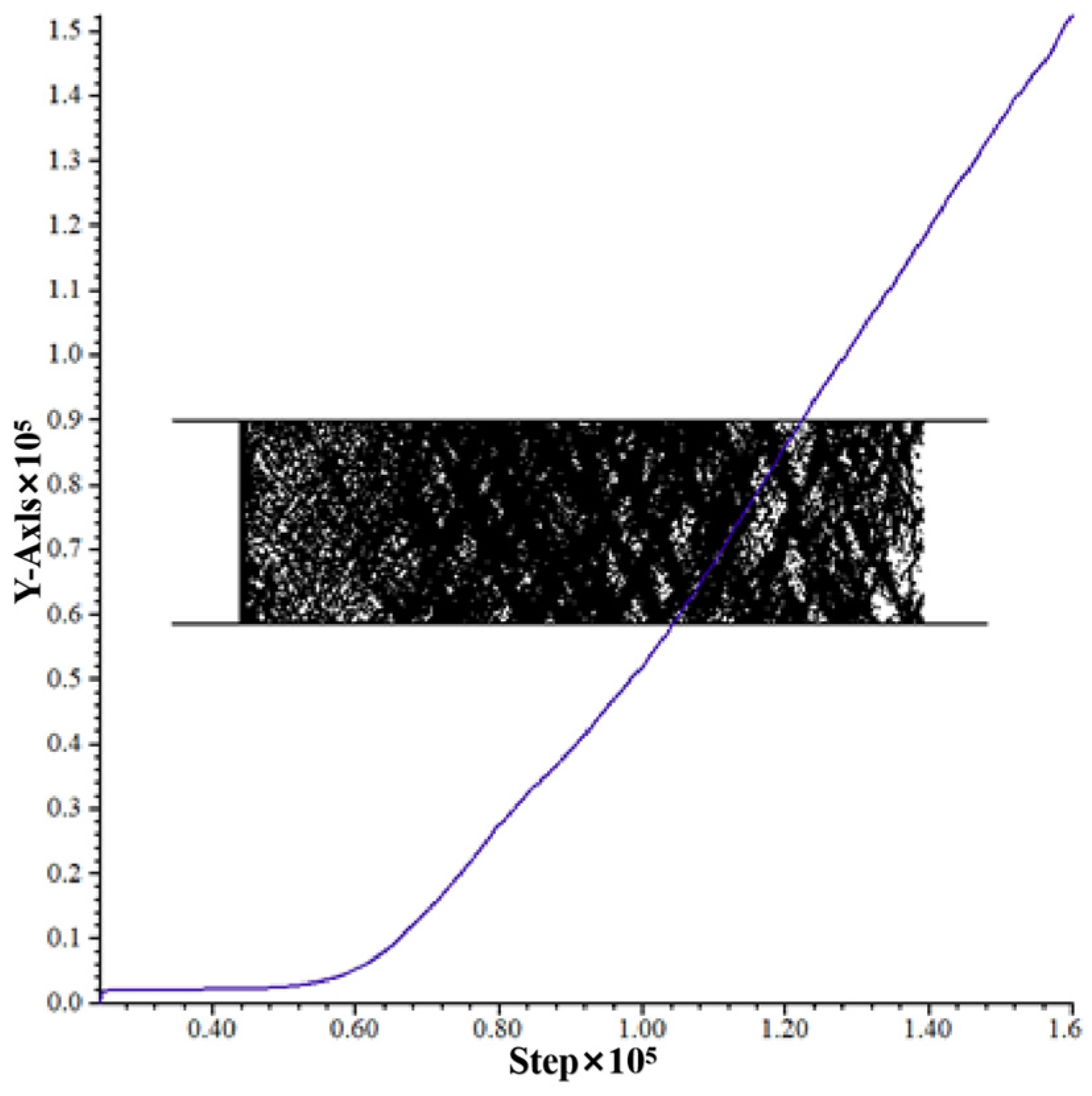
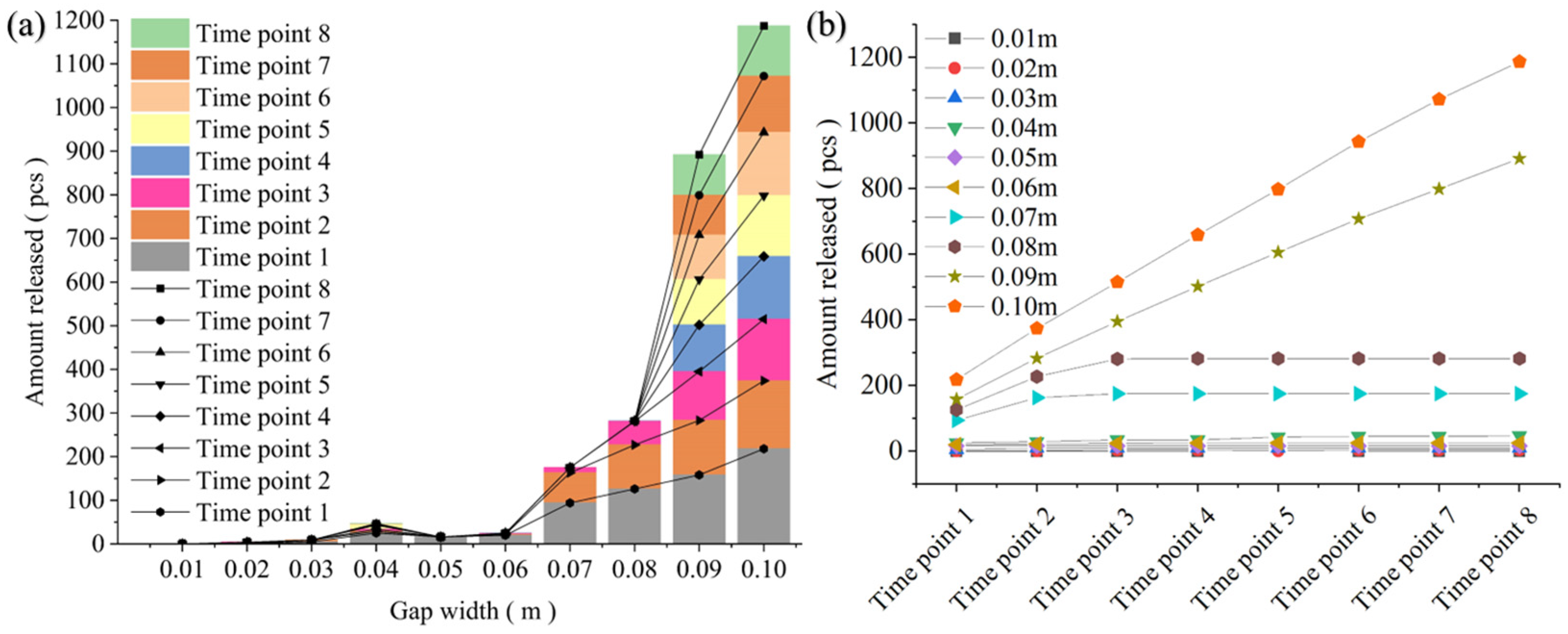
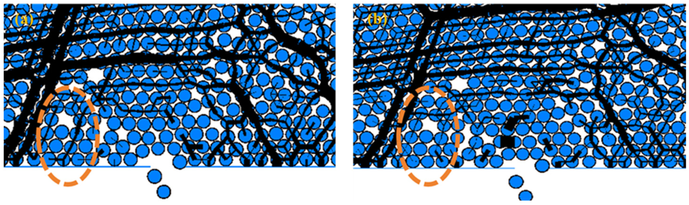
3.2. Characteristics of Coal Leakage between Hydraulic Supports

The simulation of the working face environment reveals that the critical area for top coal crushing is located at the end of the coal wall in the roof control zone and behind the support. During the initial stage of coal body crushing, an elastic phase characterized by gradual deformation occurs, allowing for the timely implementation of measures to prevent leakage. The crushing process as a whole is shifted from the back of the support to the coal wall section, providing a reference for the leakage prevention and stopping process.
The investigation of the spillage process after top coal crushing in the crushing section is conducted by transforming it into the normal direction of the working face based on simulation results. Model II’s simulation process is statistically arranged to explore eight time points with a 0.5 s interval, and the total number of particles released within each time point range is recorded [Figure 11].
When the distance between the stands ranges from one to eight times the diameter of coal particles, an initial increase in the quantity of released coal particles from each gap is observed, followed by a gradual decrease until it eventually ceases. When the distance between the racks exceeds eight times the diameter of coal particles, not only does the initial release amount of coal particles surpass that of subsequent periods, but also, this release amount remains relatively constant during these subsequent periods. Within our simulated time range, at inter-shelf gap lengths of one to six times the particle diameter, the overall discharge is approximately the same for each gap. However, for intermittent gap lengths equal to or greater than seven to eight times the particle diameter, both types exhibited significantly higher discharge amounts compared to those in previous gaps. For gap lengths larger than eight times the diameter of coal particles, there was a rapid increase in discharge, which exceeded twice that observed in previous gaps. This trend continues to amplify as inter-shelf gaps become larger.
The arching mechanism of the top coal release process, as inferred from previous laboratory coal release tests and an arching mechanical model, suggests that a smooth release of the top coal can be achieved when the gravitational component in the flow direction exceeds the combined cohesion and friction forces between the coals to be released [28,29].
The automatic cessation of particle spillage occurs when the gap between shelves is relatively small compared to the size of coal particles. This is because in the model of coal particles spilling in the gap between hydraulic supports when the top coal particles form an arch connecting the top wall of the frame through friction and mutual articulation, they cannot continue to move without the influence of external forces, and at this time, the top coal particles are said to be in a state of “becoming an arch” [Figure 12].
The black line segments represent the chain of inter-particle contact forces, specifically indicating the contact force between adjacent particles in a particle system under the influence of gravity or external loading. The thickness of these line segments indicates their respective magnitudes.
The arch depicted in the left image consists of coal leakage and particles, with its left end connected to the top of a support structure. The bottom of the arch is displaced towards the right by the pressure exerted by the top coal on its left side, resulting in friction with the upper top coal.
The type of arch in the figure on the right is called “high-level arching”, where the leakage opening does not become part of the arch formed, and both ends of the arch are connected to the top of the support, and the whole arch is subjected to the pressure of the upper bulk pointing in the direction of the leakage opening and the friction between the top coal particles within itself.
The amount of coal released during the spillage process also varies due to dynamic transient arching, which occurs when coal particles are in motion [Figure 13].
The left figure shows a noticeable high-arched ring above the opening where coal leaks out. However, this arch gets disrupted when top coal particles are unevenly pushed out on the left side over a shorter period, and it forms the shape shown in the right figure. This set of images illustrates the process of dynamic transient arch formation and destruction during flow and leakage spillage of top coal particles. When these dynamic transient arches are formed at a higher frequency within a specific time frame, the amount of coal spilled is lower. This frequency variation also leads to a large difference in the amount of coal particles spilled in different time frames. It is important to note that since this phenomenon does not repeat itself consistently, it does not have a continuous impact on the discharge rate.
The issue of self-arresting coal leakage between hydraulic supports is simplified to the problem of particle arching in infinitely long gaps, and it is analyzed through the lens of granular mechanics [30].
Set in a coal body arching above the seam, take the unit abca in the vertical planes ab and ac and the surfaces aa and bc described by the principal stress traces, which are unit lengths in the direction perpendicular to the graphic plane (see Figure 14).
Let a combined stress σ act on the planes ab and ac of the separating body and decompose σ into a shear stress τb. The gravitational force G of the separating body is taken as:
G = a Δ h ρ g
In the formula:
Δ h —Unit height
The equilibrium equation is:
G = 2 Δ h τ b
Solution:
a = 2 τ b ρ g
Taking the shear stress τb as the limit value indicated by point b in the figure, the shear stress in the limit state can be derived:
τ b = τ 0 ( 1 + sin φ )
The solution is obtained by bringing in:
a = 2 τ 0 ( 1 + sin φ ) ρ g
The formula demonstrates that the issue of inter-shelf coal leakage can be effectively addressed through modifications to the physical properties of the coal body or by controlling the width between shelves. By substituting specific parameters for the physical properties of the coal body (ρ = 1400 kg/m3, g = 9.8 m/s2, φ = 39.5°, and τ0 = 65.7 n), a value of a = 15.66 mm is obtained. This indicates that inter-shelf leakage can be effectively controlled when the width between shelves is less than eight times the particle diameter or adjustments are made to the top coal properties.
The results of the model analysis can be integrated into the working face environment to modify the characteristics of top coal particles through techniques such as water injection. Simultaneously, measures like installing nets and arranging side guards for hydraulic brackets can be implemented to reduce gap spacing, thereby effectively controlling coal leakage between hydraulic brackets.

4. Discussion

The simulations conducted in this study require a comprehensive discussion that encompasses the following key areas.
The top coal in the roof control area often undergoes disruptive effects from previous mining activities before extraction, making it impractical to apply a fragmentation model assuming an intact coal rock body as the initial state in this study. This potential for fragmentation is further magnified in extremely soft coal seams. However, simplifying the pre-mining breakage condition of the top coal is an essential approach for conducting synthesis studies [26], otherwise the complex analytical requirements will place excessive demands on computer arithmetic at this stage, making simulation data difficult to obtain. Given its considerable softness and weakness, coupled with a significantly smaller length compared to the mining zone, solid can be used to weaken the mechanical parameters of the top coal in place of the breakage of the top coal by mining disturbances. For example, Huo Yuming and Song Xuanmin used the discrete element method to analyze the fragmentation and lumpiness of the rock body and also adopted the same simplified idea [24,31].
Jin Zhongming et al. combined the field measurement data of integrated mining to derive the distribution of the top coal force in the roof control area [Figure 15] [32,33]. Combined with the figure, the stiffness difference between the top coal and the coal wall may be smaller than the stiffness difference simulated in this study, so the simulation results may have exaggerated the fracture between the front end of the support and the coal wall.
In the process of actual coal rock structure body movement, the shape of coal body particles is often irregular, which makes it easier for articulated arching behavior to occur between coal blocks. This suggests that the measured leakage of coal between shelves in real-world scenarios should be comparatively lower than under simulated conditions. Based on the physical model of bulk particle flow, Zhang Yidong and Liu Changyou et al. have simulated the movement of a coal rock body at the back of the corresponding hydraulic support [28,34,35]. This experiment truly reflects the existence of these inaccuracies.
The size of the model frame used in the experiment is 130 cm long and 12 cm wide, and the width of the simulated bracket is 6 cm. The data of the simulated hydraulic bracket are shown in Table 3, and the parameters of the experimental bulk material are shown in Table 4.
In Figure 16b, the simulated particles form a lower-positioned arch at the coal release opening, and the particles are articulated. The right side of the arch is connected to the coal release opening. The arch formed by the particles in Figure 16c is at a higher position above the coal release opening, and the arch is not connected to the coal release opening, but it also stops the flow and release of top coal at the coal release opening.
Further, we substitute the morphology parameters of the broken top coal block simulated under the parallel bonding intrinsic condition into the inter-shelf coal particle spilling model. We simulate and investigate the conditions of arching and spontaneous stopping of inter-shelf coal spillage and the change rule of block particle flow under complex particle size and morphology conditions. This method has been used in the study of bulk media flow at the coal discharge port in the early stage and has achieved certain research results [36].

5. Conclusions

1. The PFC2D software was used to establish a discrete element numerical model of top coal crushing in the upper control area, thus simulating the process of top coal fragmentation in that region. Subsequently, an analysis was conducted on the comminution behavior of the top coal, including observing and documenting fissure generation as well as changes in bulkiness. It was concluded that the primary mechanism for crushing soft coal seams involves sequential stages such as fissure initiation, propagation, secondary development, and penetration. Areas such as the junction of the top coal and coal wall and the tail of the support were identified as the main crushing areas of top coal.
2. The discrete element numerical model of top coal spillage under different hydraulic support spacing conditions was established, and the mutual control relationship between hydraulic bracket spacing and particle lumpiness was analyzed and concluded: when the rack spacing is less than or equal to eight times the diameter of lumpiness, the coal particles between the hydraulic support racks can naturally form an arch and stop the spillage.
3. After analyzing the issue of coal leakage in Chaochuan Mine, in the studied working face of JI 16-17-21180, the average time saving for a single shift of manual floating coal cleaning in the working face after the process modification (including roof netting, increasing side guards of hydraulic support, water injection in long and short holes, etc.) is about 2 h, and the proportion of time saving is more than 50~75%. The control method has been popularized in the adjacent working faces of JI 16-17-22010 and JI 16-17-22030.
The results of the study provide a research proposal for the coal leakage problem between hydraulic supports when using integrated mining in extremely soft and thick coal seams, and provide a solution reference for the coal leakage problem between hydraulic supports. However, there are some limitations in this study; while the problem focuses on the gap between the top beams of the hydraulic supports, this study ignores other real spillage situations such as the spillage of coal particles at the tail beams of the hydraulic supports and at the coal discharge ports, so in a subsequent study, the coal particle exits from each place of the hydraulic supports of the integrated mining can be studied as a whole, or the spillage of coal particles from the top of the rear of the supports can be studied specifically.

Author Contributions

Conceptualization, P.Y. and X.W.; methodology, S.Z.; software, P.Y. and S.Z.; validation, P.Y. and S.Z.; formal analysis, S.Z. and X.W.; investigation, S.Z.; resources, X.W.; data curation, S.Z.; writing—original draft preparation, S.Z.; writing—review and editing, P.Y.; funding acquisition, X.W. All authors have read and agreed to the published version of the manuscript.

Funding

This research was funded by the National Natural Science Foundation of China, grant number 52374146.

Data Availability Statement

Data are contained within the article.

Conflicts of Interest

The authors declare no conflicts of interest.

References

  1. Wu, F.F.; Zhang, S.R.; Yue, X.; Liu, C.; Liu, Q.; Zhang, J.; Lv, B.; Gao, Z. Study on mechanism and improvement technology of Top coal loss in horizontal sublevel fully mechanized caving mining. Energy Explor. Exploit. 2022, 40, 1394–1408. [Google Scholar] [CrossRef]
  2. Yang, L.; Wang, J.C.; Yang, S.L.; Li, L.H.; Wu, S.W. Improving the top coal recovery ratio in longwall top coal caving mining using drawing balance analysis. Int. J. Min. Reclam. Environ. 2023, 37, 319–337. [Google Scholar] [CrossRef]
  3. Song, X.H.; Zhu, D.F.; Wang, Z.L.; Huo, Y.M.; Liu, Y.Y.; Liu, G.F.; Cao, J.J.; Li, H.C. Forty years of integrated mining in China’s coal mines: Progress in theory and technical equipment research. Coal Sci. Technol. 2021, 49, 1–29. [Google Scholar]
  4. Wang, J.C. 40 years and prospects of integrated mining in China. J. China Coal Soc. 2023, 48, 83–99. [Google Scholar] [CrossRef]
  5. Wang, J. Research on the Coal Rock Release Pattern and Coal Release Process Parameters of Large-Height Generalized Mining of Thick Coal Seams. Master’s Thesis, China University of Mining and Technology, Xuzhou, China, 2008. [Google Scholar]
  6. Wei, J.P. Research on the Fracturing Pattern and Arching Mechanism of Top Coal in the Integrated Face. Doctoral Dissertation, Taiyuan University of Technology, Taiyuan, China, 2004. [Google Scholar]
  7. Xue, B.; Zhang, Y.; Li, J.; Wang, Y. A review of coal gangue identification research-application to China’s top coal release process. Environ. Sci. Pollut. Res. 2023, 30, 14091–14103. [Google Scholar] [CrossRef] [PubMed]
  8. Zhang, N.B.; Liu, C.Y.; Chen, B.B.; Zhu, C.Q.; Zhou, J.F. The flow pattern of coal gangue release and determination of parameters of coal release process in thick coal seam under extremely close coal seam. J. Min. Saf. Eng. 2021, 38, 911–918. [Google Scholar]
  9. Wang, J.C.; Fu, Q. Theory and application of bulk medium flow for top coal release in low-level integrated mining. J. China Coal Soc. 2002, 1, 337–341. [Google Scholar]
  10. Wang, J.C.; Li, Z.G.; Chen, Y.J.; Zheng, H.F. Experimental study on the theory of bulk media flow in top coal release of integrated mining. J. China Coal Soc. 2004, 3, 260–263. [Google Scholar]
  11. Zhang, J.W. Simulation Study on Three-Dimensional Release Law of Bulk Top Coal in Integrated Mining. Doctoral Dissertation, China University of Mining and Technology (Beijing), Beijing, China, 2017. [Google Scholar]
  12. He, G.R.; Wang, N.; Zhang, J. Key technology and management of circular arc section of large inclination angle “three soft” extra thick coal seam working face. Coal Sci. Technol. 2023, 1, 1–12. [Google Scholar]
  13. Wang, L.; Wang, M.Y.; Yan, H.B.; Yan, W.T.; Chen, J.J. Research on the mode and mechanism of overburden subsidence in “three soft” coal seams. Coal Technol. 2023, 42, 28–31. [Google Scholar]
  14. Wang, X.F.; Wang, Y.; Zhang, D.S. Research on strengthening support technology for key parts of large inclination angle “three soft” coal seam roadway. J. Min. Saf. Eng. 2017, 34, 208–213. [Google Scholar]
  15. He, X. Research on the Breakage and Release Pattern of Thick Hard Top Coal and Cracking to Promote Release in Shenshubian Coal Mine. Master’s Thesis, China University of Mining and Technology, Xuzhou, China, 2020. [Google Scholar]
  16. Wang, J.C.; Zhang, J.W. BBR study on top coal release pattern of integrated mining. J. China Coal Soc. 2015, 40, 487–493. [Google Scholar]
  17. Zhang, N.B.; Liu, C.Y.; Chen, Y. Numerical simulation study of gangue flow field law in unstable thick coal seam roof coal mining. Coal Technol. 2014, 33, 1–4. [Google Scholar]
  18. Du, L.F. Research on Coal Releasing Process of Group Coal Releasing in Integrated Mining of Extra-Thick Coal Seam in Tashan Coal Mine. Master’s Thesis, Research Institute of Coal Science, Beijing, China, 2020. [Google Scholar]
  19. Du, L.F.; Xie, X.Z.; Zhao, T.L. Analysis of spatial and temporal field coupling of coal top coal at the beginning of multiple coal discharge port comprehensive mining. Coal Sci. Technol. 2019, 47, 56–62. [Google Scholar]
  20. Wang, X.F.; Chen, X.Y.; Wang, J.Y.; Chang, Z.C.; Qin, D.D. Creep damage mechanism and control of perimeter rock in deep soft rock tunnel in Pingdingshan mine. J. Min. Saf. Eng. 2023, 40, 1139–1150. [Google Scholar]
  21. Wang, X.F.; Jia, J.F.; Yang, Z.B.; Zhao, W.L.; Wang, J.Y.; Yang, P.J.; Yang, Q. Determination of the strength of high-foam filler at the top of ultra-high roadway in very soft and thick coal seams. J. Min. Rock Control. Eng. 2023, 5, 77–87. [Google Scholar]
  22. Skrzypkowski, K.; Korzeniowski, W.; Nguyen Duc, T. Choice of Powered Roof Support FAZOS-15/31-POz for Vang Danh Hard Coal Mine. Inżynieria Miner. 2022, 2, 2–13. [Google Scholar] [CrossRef]
  23. Zeng, Q.; Li, Z.; Wan, L.; Ma, D. Study on Roof Instability Effect and Bearing Characteristics of Hydraulic Support in Longwall Top Coal Caving. Appl. Sci. 2023, 13, 8102. [Google Scholar] [CrossRef]
  24. Huo, Y.M. Mechanism of Top Coal Crushing and Intelligent Coal Release Control in Integrated Mining of Thick Coal Seams. Doctoral Dissertation, Taiyuan University of Technology, Taiyuan, China, 2021. [Google Scholar]
  25. Mao, H.J.; Guo, Y.T.; Wang, G.J.; Yang, C.H. Evaluation of the effect of clay mineralogical composition on hydration. Geotechnics 2010, 31, 2723–2728. [Google Scholar]
  26. He, X.; Liu, C.Y.; Wu, F.F.; Peng, K.P.; Yang, J.X. Study on the influence of elevation angle on top coal release pattern in upward sloping generalized mining coal seams. Coal Sci. Technol. 2021, 49, 25–31. [Google Scholar]
  27. Han, Y.F.; Wang, Z.H.; Tang, Y.S. Characterization of zonal damage of top coal in integrated mining of thick coal seams. Coal Sci. Technol. 2022, 50, 99–107. [Google Scholar]
  28. Liu, C.Y.; Huang, B.X.; Wu, F.F.; Wan, Z.J.; Yang, P.J. Block size theory and application for breaking and venting top coal in generalized mining. J. Min. Saf. Eng. 2006, 1, 56–61. [Google Scholar]
  29. Liu, C.Y.; Zhang, N.B.; Guo, F.Q.; An, S.; Chen, B.B. Temporal pattern and identification method of coal-gangue-rock release flow in a thick coal seam. J. China Coal Soc. 2022, 47, 137–151. [Google Scholar]
  30. Huang, S.Y. Bulk Mechanics; Mechanical Industry Press: Beijing, China, 1993. [Google Scholar]
  31. Song, X.M. Correlation study on the distribution and blockiness of top coal fissures in top coal mining. J. China Coal Soc. 1998, 2, 40–44. [Google Scholar]
  32. Jin, Z.M.; Wei, J.P.; Jin, W.W. Characteristics of support pressure distribution in front of a roof coal mine. J. Taiyuan Univ. Technol. 2001, 3, 216–218. [Google Scholar]
  33. Jin, Z.M.; Kang, T.H.; Gong, P.L.; Song, X.M. Correlation between fractal fracture and top coal emplacement in coal bodies. J. Rock Mech. Eng. 1996, 2, 48–54. [Google Scholar]
  34. Jin, Z.M.; Zhang, H.X.; Song, X.G.; Kang, T.H. Study on the deformation and motion law of top coal in general-purpose mining field. Mine Press. Roof Manag. 1992, 1, 26–31. [Google Scholar]
  35. Song, X.H.; Qian, M.G.; Jin, Z.M. Study on the distribution law of top coal lumpiness in roof coal mining. J. China Coal Soc. 1999, 1, 39–43. [Google Scholar]
  36. Xu, Y.X.; Wang, G.F.; Li, M.Z.; He, M.; Zhang, J.H.; Zhou, C.T.; Han, H.J. Numerical simulation study of integrated mining of extra-thick hard coal seams based on bonded particle model. J. China Coal Soc. 2019, 44, 3317–3328. [Google Scholar]
Figure 1. Mines were selected for the study. (a) Topographic and geographic division map of Henan Province, China; (b) Topographic map of Ruzhou City and county and city adjacencies, location of the Chaochuan Mine.
Energies 17 01013 g001
Figure 2. Comprehensive geologic column map of Chaochuan Mine.
Energies 17 01013 g002
Figure 3. Coal samples and their fine structure. (a) The sample of crushed particles obtained in the field; (b) crushed particle; (c) coal particles at 1000 magnification; (d) coal particles at 1000 magnification; (e) coal particles at 1600 magnification; (f) coal particles at 1600 magnification; (g) clay minerals calibrated in XRD tests.
Energies 17 01013 g003
Figure 4. Schematic diagram of the principle of parallel bonding modeling. (a) Particle–parallel bonding bond relationship; (b) intrinsic relationship.
Energies 17 01013 g004
Figure 5. Diagram of the linear bond model. (a) Particle to linear stiffness bond relationship; (b) intrinsic relationship.
Energies 17 01013 g005
Figure 6. Calibration of analog parameters. (a) Sampling locations; (b) mechanical testing experiments on samples.
Energies 17 01013 g006
Figure 7. Controlled top distance top-coal-crushing model.
Energies 17 01013 g007
Figure 8. Model of coal leakage between racks.
Energies 17 01013 g008
Figure 9. Temporal characteristics of top coal crushing simulation. (ad) denote the development of top coal fracture and stress concentration at different time points, respectively.
Energies 17 01013 g009
Figure 10. Statistics on the number of fissures.
Energies 17 01013 g010
Figure 11. Coal leakage with different rack spacing. (a) Release at different hydraulic support rack spacing; (b) release at different time points.
Energies 17 01013 g011
Figure 12. The arching state between frames. (a) arching at the coal leakage opening; (b) arching at the high-level.
Energies 17 01013 g012
Figure 13. Dynamic transient arch formation and destruction. (a) Dynamic transient arch formation; (b) dynamic transient arch destruction.
Energies 17 01013 g013
Figure 14. Coal body arching between shelves.
Energies 17 01013 g014
Figure 15. Distribution of force on the top coal at the control top distance.
Energies 17 01013 g015
Figure 16. Arching phenomenon in bulk experiments. (a) Bulk model; (b) arching at the coal leakage opening; (c) arching at a high level.
Energies 17 01013 g016
Table 1. Micro-parameters of particles.
Density/(kg/m3)Normal to Tangential Stiffness Ratio/(kn/ks)Contact Modulus/GPaFriction Coefficient/fNormal Bond Strength/MPaTangential Bond Strength/MPa
14001.5500.51050
Table 2. Model particle mechanics parameter table.
Rock StratumThickness/mNormal Stiffness/GPaTangential Stiffness/GPaCapacity/N/m3Equivalent Diameter/mPorosityCoefficient of Friction
gangue14625000.05~0.060.20.55
top coal0.54414000.0095~0.01050.10.30
Table 3. Model bracket size comparison.
Width of Hydraulic SupportDeduce the Highest LevelMinimum Roof Control Distance
Porosity
Height of Coal Discharge OpeningCoal Miner Cut-off Depth
Actual/mModel/mActual/mModel/mActual/mModel/mActual/mModel/mActual/mModel/m
1.562.39.24.5918.361.14.40.62.4
Table 4. Experimental parameters of the crushed top coal rock body.
StratumActualModel
Thicknesses/mLump Size/mmThicknesses/cmLump Size/mm
top coallower part1.01253.105
upper section2.0437.56.2017.5
immediate rooflower part2.5187.54.997.5
upper section3.55006.7420
main rooflower part2.02504.5810
central section2.03005.212.5
upper section2.03755.215
overlying stratafull3.5100014.540
Disclaimer/Publisher’s Note: The statements, opinions and data contained in all publications are solely those of the individual author(s) and contributor(s) and not of MDPI and/or the editor(s). MDPI and/or the editor(s) disclaim responsibility for any injury to people or property resulting from any ideas, methods, instructions or products referred to in the content.

