
A Comprehensive Review of the Establishment of Safety Zones and Quantitative Risk Analysis during Ship-to-Ship LNG Bunkering


1
Department of Marine System Engineering, Korea Maritime and Ocean University, 727, Taejong-ro, Yeongdo-gu, Busan 49112, Republic of Korea
2
Gas Technology Team, Busan Mieum Headquarters, Korea Marine Equipment Research Institute, Busan 49111, Republic of Korea
3
Division of Coast Guard Studies, Korea Maritime and Ocean University, 727, Taejong-ro, Yeongdo-gu, Busan 49112, Republic of Korea
*
Authors to whom correspondence should be addressed.
Energies 2024, 17(2), 512; https://doi.org/10.3390/en17020512
Submission received: 19 December 2023
/
Revised: 17 January 2024
/
Accepted: 19 January 2024
/
Published: 20 January 2024
(This article belongs to the Section K: State-of-the-Art Energy Related Technologies)
Abstract
:This study comprehensively reviews the current academic literature concerning the safety and risk assessment associated with the utilization of liquefied natural gas (LNG) in ship-to-ship bunkering scenarios. Simultaneously, it explores the complex system of regulations, standards, and guidelines that oversee the thorough evaluation of risks linked to ship-to-ship LNG bunkering procedures. Special attention is given to the scrutiny of legal frameworks that encompass a range of safety considerations, such as storage facilities, transportation, bunkering processes, and the vessels involved in both bunkering and receiving. The research questions are formulated to provide a clear direction and objectives for this study’s journey. The main hazards and risks related to LNG bunkering are identified and analyzed. The legal framework for LNG bunkering risk assessment is analyzed, and opportunities for improvement in these legal documents are identified. The general methodology and procedure for the safety assessment of the LNG bunkering process are summarized and established. From an extensive compilation of scholarly articles, 210 high-quality research papers have been deliberately selected for thorough examination. The research gaps are identified and analyzed. Through this analysis, the highlighted studies and key points are mentioned and analyzed. The research gaps are also outlined to predict the future directions of research on establishing safety zones during LNG ship-to-ship bunkering. Recommendations are made to propose improvements to the legal documents and suggest further research on the establishment of safety zones during ship-to-ship LNG bunkering to relevant authorities.
1. Introduction
International shipping stands out as a highly effective means of transportation [1,2]. It encompasses more than 80% of total transportation volume, while concurrently being a significant and expanding contributor to the release of greenhouse gases (GHGs) [3,4]. The emissions from shipping activities reached 1076 million tons of CO2 in 2018 [5], contributing approximately 2.9% to the overall human-caused global emissions [6,7]. As a result, maritime transportation is actively seeking opportunities to significantly decrease its global GHG emissions arising from its shipping activities. The International Maritime Organization (IMO) has adopted goals to achieve a minimum 50% reduction in GHG emissions by the year 2050. Furthermore, the IMO aims to achieve a reduction of 40% in CO2 emissions per unit of transportation by 2030 and a 70% reduction by 2040 in comparison to the levels recorded in 2008 [8,9] and has set a target of net zero emissions by 2050 [10]. To improve the efficiency of energy utilization in ships and decrease CO2 emissions, the IMO has implemented MARPOL Annex VI [11]. Additionally, regulations such as SEEMP [12], EEDI [13], and EEOI [14] were also enacted on 1 January 2013, in accordance with the IMO’s directives [15]. Developing alternative fuels is crucial to fulfilling the requirements of maritime shipping [16]. Hydrogen presents itself as a carbon-neutral energy option possessing a significant mass energy density [17]. It has the potential to serve as fuel in a range of technologies, including internal combustion engines (ICEs), fuel cells [18], and gas turbines, aiming to achieve environmentally friendly emission objectives. Nonetheless, hydrogen possesses a limited volumetric density, which translates to the necessity for ample storage room and shorter ship transport durations when employed as maritime fuel [19]. This mainly results in disadvantages related to economic sustainability and the effectiveness of vessel management. Consequently, there arises a demand to discover a means of transporting hydrogen as fuel that can fulfill both emission reduction objectives and the operational necessities of vessels [20]. In line with this pattern, the utilization of LNG as a substitute for traditional maritime fuel has garnered growing interest from those involved in maritime activities.
LNG appears nearly odorless and colorless and is primarily composed of methane (typically more than 80% of its content) along with varying proportions of propane, ethane, butane, etc. The methane gas can transform into a liquid state at temperatures lower than −82 °C, and it is stored under approximately atmospheric pressure at a temperature of approximately −162 °C. Vessels intending to refuel with LNG according to the IGF Code are required to meet specific design and feature criteria, while their operators must fulfill distinct training and qualification prerequisites. For LNG-fueled ships, there are four available options for obtaining LNG bunkering through existing technology and equipment:
- (i)
- Ship-to-ship (STS) LNG bunkering;
- (ii)
- Truck-to-ship LNG bunkering;
- (iii)
- Terminal-to-ship LNG bunkering;
- (iv)
- Portable LNG tanks as fuel storage.
Each of these bunkering methods involves distinct regulations and equipment. Among them, the STS LNG bunkering approach offers greater flexibility and capacity for delivering larger quantities of LNG. STS LNG bunkering operations can be conducted either within port areas or in open waters, presenting several operational benefits. These operations can occur alongside facilities or at anchorages within port limits via fuel hoses. However, conducting LNG bunkering while ships are in motion is unconventional and should not be attempted without proper STS mooring and fendering systems in place. Every potential danger linked with STS transfer operations involving LNG includes risks like collisions, mooring mishaps, cargo transfer hose breakdowns, personnel fatigue and availability, simultaneous operations, and various other factors [21].
The discharge of LNG and other sub-zero temperature liquids, particularly those below −40 °C [22], can result in significant harm to materials like steel apart from cryogenic-grade steel [23]. Stainless steel will maintain its malleability, while carbon steel and low-alloy steel will turn fragile, leading to the potential for fractures when subjected to the extreme cold of liquefied natural gas [24]. In case of unexpected release, the chance of a gas cloud igniting without causing substantial overpressure exists [25]. To achieve this, the LNG needs to vaporize initially, leading to the creation of a potentially explosive atmosphere with a methane concentration falling between the lower flammable limit (LFL) and the upper flammable limit (UFL) [26]. These boundaries are set at 5% and 15% [27,28], respectively.
Owing to the absence of previous expertise in the comprehensive review and analysis of safety assessment during the ship-to-ship LNG bunkering process, a substantial endeavor is necessary to comprehend and establish safety protocols for LNG facilities and the process of bunkering at ports. According to the definition provided by the Society for Gas as a Marine Fuel [29], the International Organization for Standardization [30], and the Classification Society, the safety zone during the LNG bunkering process is described as a three-dimensional envelope wherein natural gas/LNG may be present due to a leak/incident. This zone poses a recognized potential to cause harm to life or damage to equipment/infrastructure in the event of a gas/LNG leak. It is important to note that this zone is temporary and exists only during bunkering. The primary objective of establishing a safety zone is to mitigate the likelihood of igniting spilled natural gas. The underlying philosophy is that, while the occurrence of an LNG release should always be avoided, the absence of ignition in a dispersing cloud eliminates the risk of fire. Preventing ignition serves as a crucial component of the second layer of defense. This is accomplished by restricting access to the defined safety zone, thereby ensuring that only essential personnel and activities are allowed within. Consequently, the number of individuals in the proximity of activities with potential exposure to fire hazards is minimized, contributing to overall risk reduction.
Regarding risk evaluation, two primary methods exist for defining the safety zone during the LNG bunkering process [31,32]: the deterministic and the risk-based method (see in Figure 1). The selection between these two approaches depends on the specific bunkering scenario being targeted [33,34]. Typically, for common scenarios like port-to-ship, STS, and truck-to-ship bunkering, a qualitative method will be utilized [35]. On the other hand, a quantitative approach (a risk-based approach) is more suitable for other situations [36]. Considering that the discussed LNG facilities frequently adopt a fundamental approach, an unintended LNG leak during bunkering can be treated as a single accidental leakage event. The scenario chosen represents the most severe or unique conditions of a leak occurring during bunkering, and from there, a rough estimation of the necessary safety distance around the facility is calculated, considering the range of flammable limits and dispersion characteristics. At present, the majority of safety zones associated with the bunkering process for ships powered by LNG are established utilizing those approaches. This is due to the fact that this framework typically conducts its bunkering procedures under standard scenarios, with limited room for additional activities during operations.
The establishment of the safety zone considers both the calculated risks and the acceptable risk threshold. When handling LNG-fueled ships simultaneously (SIMOPS), it becomes crucial to integrate extra considerations into the risk assessment. These factors encompass the proximity of other vessels or structures, prevailing weather conditions, and potential environmental consequences. These approaches ensure the identification and mitigation of all conceivable risks, thereby minimizing the likelihood of accidents and maintaining the safety of the facility and its surrounding environment. To summarize, the safety zone must consistently remain under control, and its dimensions will be contingent upon several factors, including:
- The design specifications of the LNG bunkering infrastructure and LNG-fueled ship;
- The configuration of the LNG transfer system in place;
- Parameters such as the flow rate, duration, and pressure associated with the potential leak source, as well as the concentration fraction of the lower flammable limit of fuel;
- The prevailing weather conditions and ambient temperature during the bunkering operation;
- The layout of the location where spills could potentially occur, etc.
However, there is currently no detailed international code or guideline precisely defining a safety zone during the bunkering process, and each regulation exhibits slight variations. Consequently, a comprehensive review and understanding of existing standards and guidelines are essential to identify any discrepancies and ensure coherence before their definitive application in both design and operational phases. Furthermore, a thorough and extensive review of current research and research gaps in risk assessment during the bunkering process is imperative. This paper serves as a shared platform for readers, encompassing designers and safety experts, facilitating easy access to and comparison of diverse regulations, scientific research, and recommendations. The goal is to establish a foundation for achieving a safe and efficient LNG bunkering process. This analysis is intended to respond to the following research questions:
- ①
- What are the primary risks connected with the use of LNG as a fuel?
- ②
- Do the current regulations and standards adequately encompass all facets of ship-to-ship LNG bunkering safety? Do safety regulations have any discrepancies or areas where they do not align?
- ③
- Are there any areas in scientific research and comprehension of LNG bunkering safety that remain unaddressed?
- ④
- What are the obstacles and recommendations for enhancing LNG bunkering safety?
The initial research question is addressed and explored in the literature review, spanning Section 1, Section 2 and Section 3 of this study. The second and third questions are addressed through a meticulous examination of relevant legislations, standards, guidelines, and scientific research publications pertaining to LNG bunkering. Challenges and recommendations are subsequently formulated based on the gathered insights.
2. Characteristics of LNG
2.1. General Information and Physical Properties of LNG
Natural gas is a fossil fuel, indicating its formation from organic matter that was deposited and buried in the Earth millions of years ago. LNG is a liquid mixture of various gases, primarily consisting of methane (CH4), and its mass concentration can range from 70 to 99% depending on the source of origin [37]. LNG possesses no odor, has no color, and is non-corrosive, non-flammable, and non-toxic [38]. Additionally, LNG typically contains other hydrocarbon components, including ethane (C2H6), propane (C3H8), and butane (C4H10), while minor quantities of gases like nitrogen (N2) may also be present. The reserves of natural gas are substantial, with the International Energy Agency (IEA) estimating that, based on current consumption rates as of January 2011, these reserves could last for more than 250 years. When natural gas undergoes liquefaction at around −162 , its volume is drastically reduced to approximately 1/600th in the gaseous state. In this liquefied state, LNG is stored in tanks, and the entry of heat causes the formation of boil-off gas (BOG). This BOG is either utilized by the engines or re-liquefied to keep the LNG tank pressure within acceptable ranges. A thorough understanding of the LNG saturation vapor curve and its impact on bunkering is essential for enhancing bunkering processes.
The basic properties of LNG are presented in Table 1.
LNG exhibits distinct characteristics in comparison to HFO, with approximately half the density and a calorific value approximately 20% higher [41]. When all factors are considered, a ship aiming to achieve the same range using LNG must bunker approximately 1.8 times more fuel [42].
In its liquid state, LNG is non-flammable, unlike methane vapors, which possess flammability. When the volumetric ratio of methane to air falls within the range of 5–15%, the mixture is considered flammable. Methane itself is colorless; however, when cold LNG vapor escapes into the atmosphere, its low temperature leads to the condensation of surrounding air, creating a distinctive white cloud on the sea’s surface.
The composition of LNG fuel plays a pivotal role in shaping the performance of the engines that use it [43]. Consequently, this has an impact on the speed and fuel consumption of the vessel during a voyage. LNG containing a higher methane concentration may exhibit a reduced calorific value compared to LNG with lower methane levels. This implies that more fuel is required to achieve an equivalent power output. It is crucial to consider these potential performance variations when establishing vessel performance guarantees in the charter party.
2.2. LNG Bunkering Considerations
Incorporating bunkering planning into the initial stages of a design project is crucial for achieving optimal efficiency. When the trading route is known and the prospective bunker supplier is identified during the design process, it is recommended to implement measures and contracts aligning the specifications of the LNG vessel with those of the supplier or bunker vessel during bunkering. This facilitates the standardization of bunkering procedures. Conversely, in cases where trading routes and suppliers are uncertain during the design phase, it may be beneficial to contemplate raising equipment limits on the vessel. This ensures effective management of any potential issues that may arise during bunkering.
Two crucial considerations revolve around the temperature and pressure control of bunkers:
- (i)
- The colder the LNG supplied by the bunker vessel, the more advantageous for the FGSS. This lower temperature offers greater flexibility in managing pressure control within the storage tanks. Conversely, if the LNG from the bunkering vessel is warmer, it may lead to increased boil-off and pressure issues, potentially resulting in higher fuel consumption to address these pressure-related challenges.
- (ii)
- Temperature-related issues are compounded by the necessity to evaluate the compatibility of the vapor return system in LNG gas carriers or bunker vessels during a compatibility study with the gas-fueled vessel. Ensuring alignment in the vapor balancing design between the supplier and the receiver is critical. This becomes especially crucial as bunkering tanks increase in size, prompting owners to consider the implications of the cool-down process of the bunker tank before full-rate loading and the management of the generated flash gas. Neglecting these factors could disrupt the bunkering operation’s duration, potentially affecting the anticipated operational profile.
Additionally, apart from vapor balancing design compatibility, challenges may arise concerning documenting custody transfers. In addition to quantifying the LNG supplied to the GFS, measuring vapor return becomes necessary. Credits for the return of gas vapor need to be considered in the overall pricing structure during custody transfer. Moreover, it is essential to factor in other considerations, including the location of the bunker station and the compatibility between the bunker vessel and the receiving system.
2.3. Accidents in LNG Bunkering
While the use of LNG-fueled ships has been in practice for nearly five decades, there have been some accidents either at sea or in ports. This also holds true for LNG carriers; some documented incidents but they did not lead to fires, explosions, or hull failures [44]. LNG leak incidents occurring in LNG facilities and tanks have demonstrated their significant environmental consequences.
On 1 April 2014 [45], an explosion stemming from a gas incident occurred at an LNG facility in Washington, United States. This explosion resulted in severe burns for one worker, as well as injuries to four additional individuals. Furthermore, the extensive fire compelled the evacuation of 400 residents living within a two-mile radius of the facility [46,47]. Given that ship-to-ship bunkering is normally in open areas, an LNG fuel leak incident occurring within one can rapidly result in an escalation of gas concentration. This situation poses a severe risk of fire or explosion, thereby posing significant threats to the safety and well-being of individuals. Table 2 provides a compilation of documented accidents and their ensuing consequences stemming from LNG leaks.
In addition to the environmental advantages, it is crucial to thoroughly assess the reliability and safety of LNG utilization. In the event of an accidental release of LNG, rapid evaporation and dispersion may occur, potentially endangering the surrounding area. This could lead to risks such as asphyxiation, cryogenic burns, structural damage, fires, and the potential for a vapor cloud explosion (VCE) arising from the presence of a natural gas cloud [48]. The presence of obstructions within processing equipment can significantly heighten the risk of a VCE. As combustible gas accumulates in substantial quantities, the gas cloud may inadvertently ignite, potentially leading to a catastrophic and devastating explosion [53]. In the event of an accident, a chain of events can lead to simultaneous or consecutive consequences, including a gas leak, fire, VCE, and BLEVE, collectively referred to as the “domino effect”. For instance, a jet fire capable of heating a pressurized liquid vessel to its boiling point can trigger a BLEVE, culminating in a catastrophic accident [54]. A singular explosion often serves as the catalyst for the domino effect, which can lead to the occurrence of gas leaks and fires in the vicinity of the initial explosion [55]. Blast, heat, or fragmentation has the potential to harm nearby systems, leading to equipment failures. Conducting explosion research within an LNG processing plant entails substantial expenses. Such experiments require a full-scale model and should be conducted at a safe distance from populated areas. An alternative approach is to employ CFD/simulation software for explosive analysis and research. The CFD methodology has made significant advancements in recent years, enabling the accurate prediction of complex VCE [56].
3. Risks Associated with LNG as a Marine Fuel
Natural gas, predominantly composed of CH4, is a non-hazardous flammable gas. The production of LNG involves cooling natural gas to a temperature lower than its boiling point, approximately −162 °C (−260 °F). The liquefaction process significantly reduces the gas’s volume by a factor of 600, enhancing efficiency for storage and transportation. LNG, being a cryogenic liquid, presents distinct risks to individuals and property in the event of a release from storage or transfer equipment compared to traditional fuel oil.
- (i)
- Primary risks involve severe injuries to individuals in close proximity who may come into contact with cryogenic liquids. LNG contact with the skin can cause effects similar to thermal burns, and exposure to sensitive areas like the eyes can result in tissue damage. Prolonged skin contact can lead to frostbite, and continued inhalation of very cold air may harm lung tissue.
- (ii)
- Steel structures exposed to cryogenic temperatures may undergo brittle fractures. The extreme coldness of LNG can render conventional shipbuilding steels brittle, potentially causing deck surface cracking or impacting other metal equipment.
- (iii)
- The creation of a flammable vapor cloud is a concern. For a fire or explosion to occur, the vapor cloud needs to fall within the flammable range, which, for methane, lies between 5% and 15% when mixed with air, and there could be an ignition. Various factors influence the potential consequences of an LNG release, including the surface of release, the quantity released, air and surface temperatures, wind speed and direction, atmospheric stability, proximity to nearby populations, and the location of ignition sources. Although ignited LNG vapors can generate substantial pressure in confined spaces like buildings or ships, there is no indication to support the claim that LNG undergoes explosion upon ignition in open and unconfined areas.
LNG presents distinct hazards, including volatility and cryogenic conditions, differing from those associated with traditional fuel oil. It is imperative for potential operators to have a clear understanding of the risks associated with LNG bunkering.
While each of the four bunkering operation methods is unique, several common initial events can lead to the release of LNG, posing risks to nearby individuals, equipment, and the environment. Figure 2 illustrates the four initial events that serve as risk factors in LNG bunkering operations and identifies typical causes for each of these events.
Effective mitigation of risks during LNG bunkering operations necessitates thorough risk assessment, adherence to safety procedures, crew training, equipment maintenance, and compliance with industry standards. Additionally, continuous monitoring and supervision are vital to ensuring the safe and efficient transfer of LNG.
In the event tree presented, the initial incident is the release of LNG, which can occur due to various factors, such as navigation failure, storage tank failure, or issues with compressors or pumps. This release can be categorized as either minor or significant. In the case of a minor release, it may result in no impact or have localized or widespread consequences. Localized consequences may lead to minor injuries, major injuries, or even fatalities, with similar outcomes for a widespread impact. Similarly, in the case of a large release, it can result in no impact or localized or widespread consequences, including scenarios such as vapor cloud dispersion, flash fires, explosions, or pool fires. The event tree functions as a tool for assessing potential outcomes of an LNG release and aids in developing strategies to prevent or minimize harm.
An observation reveals that around 71% of published papers on LNG risk analysis predominantly were reliant on traditional risk assessment methods, while about 29% of studies opted for dynamic risk assessment approaches. While conventional risk assessment effectively tackles the series of events contributing to accident scenarios, event tree analysis falls short of capturing the shared causes of failure and the interdependencies among safety barriers. Thus, it is crucial to undertake dynamic risk assessment (DRA) to enhance risk updates and allocate appropriate safety measures, considering the dynamic nature of the risks involved. A noticeable trend is emerging towards adopting more efficient integrated risk analysis tools that combine various techniques to assess the risk associated with complex and dynamic assets like LNG plants. This trend is steadily gaining momentum.
4. Regulations of LNG Bunkering
The approval of the IMO’s Initial Strategy for the reduction in GHG emissions from vessels, as expressed in Resolution MEPC.304(72) in April 2018, highlights the unwavering commitment of the IMO to uphold the principles outlined in the Paris Agreement. This strategy outlines a visionary, long-term approach to systematically eliminate greenhouse gas emissions stemming from global maritime transport over the course of this century. It has the potential to act as a proactive catalyst, inspiring member states to initiate decarbonization initiatives and enforce policies and procedures aimed at diminishing greenhouse gas emissions.
Essential guidance documents of considerable significance are accessible to support port authorities and diverse stakeholders involved in LNG bunkering at ports, offering valuable insights into optimal practices and safety recommendations for gas handling, transportation, and bunkering operations (See on Figure 3 and Table 3). These documents have been crafted by reputable organizations within the maritime industry [57]. Additionally, the subsequent regulatory provisions are collated due to their paramount impact on the LNG bunkering guidelines:
There is a degree of ambiguity regarding the commercial regulatory structure that oversees LNG infrastructure. Some stakeholders contend that regulations should extend to covering LNG outlets [60].
5. Safety Assessment of the Ship-to-Ship LNG Bunkering Process
Anticipation is widespread regarding LNG emerging as the primary alternative fuel in the future energy landscape. Its absence of SOx emissions and competitive pricing undeniably make it an attractive option for meeting the progressively stringent emissions regulations outlined by the IMO. The importance of establishing a robust bunkering infrastructure is evident, and doing so in a way that adheres to specific standards, proves economically viable, and gains public support underscores the paramount significance of safety evaluations for LNG bunkering. The general safety assessment of using LNG as a marine fuel is depicted in Figure 4.
LNG bunkering activity involves the transfer of LNG from a bunkering ship to a receiving ship. Like any bunkering procedure, safety is a top priority, and several aspects must be considered when evaluating the safety of the LNG bunkering process:
- (i)
- LNG storage and handling: Strict adherence to safety regulations is crucial for the storage and handling of LNG due to its hazardous nature. The use of storage containers specifically designed and certified for LNG is essential, and trained personnel equipped with suitable protective gear are responsible for proper handling and transfer.
- (ii)
- Bunkering procedures: Careful planning and execution of bunkering processes with trained personnel are critical. The crew of the receiving vessel must be briefed on the process and essential safety measures, and close monitoring of the process is necessary to ensure its safe execution.
- (iii)
- Ventilation: Adequate ventilation is a crucial aspect during bunkering to prevent the accumulation of LNG vapors. The bunkering area should have effective ventilation to swiftly disperse any leaks or spills.
- (iv)
- Emergency response: The well-developed emergency response plans should be readily available.
- (v)
- Regulatory compliance: The LNG bunkering process must align with applicable regulations and guidelines.
The conventional risk assessment method for establishing a vessel’s safety zone involves data gathering, scenario analysis, frequency assessment, outcome evaluation, and risk assessment. A comprehensive risk assessment for the LNG bunkering process includes hazard identification, consequence determination, risk evaluation, identification of control measures, implementation of controls, and regular monitoring and review. Considering all these aspects is imperative to guarantee the safety of the bunkering process. This procedure minimizes the risk of accidents and ensures the safe execution of the bunkering process. A flowchart summarizing the general risk assessment procedure for the LNG bunkering process is presented in Figure 5, below.
5.1. CFD and Theoretical Analysis
The LNG bunkering process can elicit heightened societal concerns due to the potential risks involved. Exposure to lethal LNG gas can result in severe consequences for humans, including blindness, lung injuries, and, in the worst cases, fatalities. Such exposure may also lead to painful effects on the eyes, nose, throat, and the respiratory system. Additionally, it is crucial to acknowledge the inherent flammability hazards associated with LNG. Despite LNG being explored as a potential maritime fuel, comprehensive information is still somewhat lacking, and limited research has been conducted to investigate the risks and safety implications of using LNG as a transportation fuel.
To prevent unforeseen damage arising from the leakage and release of LNG during the bunkering process, establishing a safety zone is imperative. This safety zone should strictly prohibit ignition sources and restrict access exclusively to authorized individuals and sanctioned activities. The release and dispersion of LNG adhere to the characteristics of heavy gas dispersion. The process of LNG leakage can be broadly divided into five primary stages. In the first stage, LNG escapes from the storage tank, pipes, hoses, or similar equipment. During this stage, LNG comes into contact with the surrounding air. As LNG is in a low-temperature state and denser than air, it accumulates as a cold pool on the ground or water surface. In this state, the release of LNG is significantly influenced by leak characteristics, including leak rate, leak hole size, and leak direction, as well as the conditions of the LNG inside the pipeline or tank, including temperature and pressure. Subsequently, in the second phase, the LNG accumulated in the low-temperature pool or water surface initiates dispersion across a broader area [61,62]. The density and composition of LNG are greatly influenced by the area of the pool. Thirdly, as the ambient temperature is typically higher than the boiling point of LNG, the LNG starts evaporating due to the surrounding heat. In this stage, the influencing factors may include heat flux, the flammability of LNG, the cargo state of the vessel, and the ship structure as well. Consequently, a broad vapor cloud with lower temperatures is generated. Lastly, it undergoes a diffusion process driven by the wind. And thus, the vapor cloud is affected by wind direction and wind speed, as well as the temperature, pressure, and humidity of the surrounding environment.
Figure 6 provides a graphical depiction of the stages of LNG leakage and diffusion. It is essential to recognize that the state of the leaked LNG, the volume of the leak, and the extent of diffusion vary at each stage of the process. Moreover, considering that LNG necessitates time for escape, heat absorption, evaporation, and dispersion, the duration of the leakage and the time needed for CFD analysis are pivotal factors in establishing the safety management zone for LNG leaks.
According to typical studies on the modelling of LNG leakage and release [14,63,64,65,66,67,68], a common block diagram for computational analysis of LNG leakage is presented in Figure 7, below.
- (i)
- Accidental release scenario: Thorough information regarding the bunkering system of an LNG bunkering ship was provided. The ship’s geometry, incorporating both intact and damaged sections resulting from a collision, was accurately modeled. The CFD analysis considered various variables, including leak location, mass flow rate, leak size, reservoir pressure, and the duration of the leak. Environmental factors, such as wind speed and direction, along with ambient temperature, were also considered during the analysis. Additionally, the thermal characteristics of LNG and steel, encompassing parameters like density, thermal conductivity, and specific heat, were meticulously integrated into the CFD material settings, utilizing tools such as FLACS-CFD, OpenFOAM, Fluent or CFX, and others.
- (ii)
- CFD simulation: All LNG release scenarios underwent comprehensive simulation. To determine an optimal grid resolution and time intervals for the LNG release model, both a grid convergence test and an iteration convergence test needed to be diligently executed. The outcomes of the gas cloud volume analysis were subsequently used to examine gas accumulation and dispersion patterns. The identification of the critical zone, defined by the gas contour at the LNG flammability limits, was also part of the analysis. Lastly, the temperature profile within the LNG bunkering structure was calculated to predict potential damage to components due to cryogenic effects.
Based on the above analysis and discussions, an algorithm diagram for assessing safety during the LNG bunkering process using CFD/simulation software is presented in Figure 8.
As illustrated in Figure 8, there are six essential steps for utilizing CFD in modeling and analyzing the consequences of LNG leakage or accidents:
- -
- Case identification: This initial step involves specifying the leakage or release scenario to be addressed in the simulation and defining the simulation’s objectives.
- -
- Software selection: Depending on the specific analysis requirements and the nature of the case, an appropriate simulation tool is chosen. Options include EFFECTS (Gexcon) and Safeti (DNV), FLACS (Gexcon), Phast, KFX (DNV), ANSYS Fluent (Ansys), etc.
- -
- Software validation and verification: Ensure the selected simulation software is validated and that it undergoes a thorough verification process. The validation process is indispensable when dealing with simulation results. Both validation and verification play a crucial role in numerical analysis, serving to mitigate errors, uncertainties, and biases that might compromise the accuracy of simulation outcomes. Errors can stem from various sources, including incorrect data, inaccurate models, numerical approximations, coding mistakes, and hardware limitations.
- -
- Pre-processing: During this stage, boundary conditions are established, and grid validation is conducted to determine the optimal grid size for the simulation. The number of grids affects calculation accuracy, with more grids providing higher accuracy but at a higher computational cost. Therefore, grid selection should strike a balance between simulation time, computational cost, and accuracy.
- -
- Scenario setup and analysis: Various factors influencing LNG leakage and dispersion are incorporated to set up scenarios. The theories governing leakage and dispersion are applied to analyze and compare results.
- -
- Result validation: The simulation results are examined and compared with the relevant theoretical literature to validate their accuracy and reliability.
As for risk-based approach methods for LNG dispersion analysis [69,70,71,72,73], the following algorithm has been developed to outline the process of risk analysis using a risk-based approach (see Figure 9).
The procedure for establishing a safety zone in this study represents an enhanced iteration of the quantitative risk assessment method recommended by [74,75,76,77,78]. The methodology employed in this research comprises five key steps, aligning with the research’s purpose and scope:
- -
- Step 1 (legal document review and experience gathering): The research commences with an examination of regulations and guidelines issued by classification societies and regulatory authorities. Insights from these sources serve as foundational references for determining safety distances in various specific scenarios.
- -
- Step 2 (data collection): Field surveys are conducted at the bunkering area to gather and measure relevant parameters, including geometry, weather conditions, and other influencing factors. Wind speed and direction are measured at specified locations. Scenarios, derived from scenario analysis, undergo an estimation of their likelihood and assessment of potential consequences in subsequent steps.
- -
- Step 3 (scenarios and consequence analysis): Diverse bunkering scenarios are developed, considering factors such as vessel dimension, loading, environmental conditions, and bunkering conditions. The frequency of each scenario can be determined by multiplying the probabilities associated with each variable under given conditions.
- -
- Step 4 (risk assessment): The probability of each accidental scenario, with an emphasis on the initial gas dispersion behavior, is portrayed through frequency analysis. Furthermore, the results of the consequence analysis are expressed in relation to critical distances and the count of casualties within these vital zones.
- -
- Step 5 (simulation results and analysis): A comprehensive examination is conducted to determine the safety distance for LNG bunkering procedures. This phase aims to identify suitable safety measures based on the collected data and the evaluated risks.
The following summarizes some theoretical research on the safety assessment of the LNG bunkering process (see Table 4).
Furthermore, several quantitative analysis studies have been cited and discussed [89,90,91,92] as well. However, there are limitations in the consequence analysis of LNG leakage conducted using simulation software, as outlined below:
- -
- The CFD model utilized for simulating LNG leakage and dispersion in specific areas, such as the port area and open sea area, requires adjustments to dimensions of weather conditions, maritime traffic, equipment, and wave conditions to align with the simulation case. Additionally, the choice of turbulence model within the simulation software, such as k-ε, k-ω, or LES Smagorinsky, can introduce variability and impact the results.
- -
- Simulations conducted in congested areas may be influenced by the presence of weather conditions (wind, temperature, etc.), humidity, and barriers, altering dispersion characteristics.
Various factors related to LNG leakage, including leak rates, leak duration, and leak directions, are considered, all of which impact the critical distance of vapor cloud dispersion. It is noteworthy that prior theoretical research has not endeavored to define safe LNG bunkering zones, creating uncertainty regarding the appropriate safety levels for certain LNG-fueled ships currently under development or in planning stages.
5.2. Experimental Studies
Cai et al. [93] conducted experiments and simulations to investigate the characteristics of natural gas explosions, the behavior of natural gas volume fractions, flame propagation, temperature variations, and shock wave overpressure. Their objective was to establish the patterns governing indoor natural gas leaks and explosion risks. The findings revealed that the flame structure can be categorized into three zones: preheat, reaction, and product zones. The primary exothermic reaction during combustion is OH + CO ⇔ H + CO2. The overall pattern of natural gas volume fraction distribution indicates that higher positions correspond to greater volume fractions. Additionally, when the distance from the leak source is the same at different heights, the volume fraction is greater. Moreover, in various leak scenarios, the natural gas volume fraction is highest when the hose disconnects. The kitchen packaging’s wrapping structure plays a significant role in the dispersion of natural gas. However, an LNG vapor cloud in the open will deflagrate and the probability that it will detonate is extremely low and can for common leaks be ignored [94].
Zhang et al. [95] created a compact experimental setup within a wind tunnel to investigate the unique physical occurrences associated with underwater leakage of LNG and the dynamic characteristics of the rising plume. The experiment utilized a high-speed camera to capture the behavior of plume ascent during underwater release of cryogenic liquid. By employing image processing methodologies, the physical model was developed and confirmed for understanding the heat transfer of cryogenic liquid beneath the water’s surface. Furthermore, Zhang et al. assessed how variations in orifice size, shape, and release pressures affected the radius of the plume.
Zhang et al. [96] conducted a comprehensive investigation into LNG jet fires occurring in a horizontal orientation, utilizing ten full-scale open field tests. The researchers employed both infrared and video cameras to observe the flames. The collected data included an analysis of flame shapes, as well as measurements and documentation of peak temperatures and heat fluxes at different flow rates. In cases where the reservoir pressure was relatively low, a minor quantity of LNG was observed spraying through the fire, leading to LNG pooling on the ground. The study established a correlation for determining flame length based on the mass flow rate.
Moreover, several other experiments have been conducted to investigate LNG leakage and dispersion. These studies are summarized in the Table 5 below.
After reviewing the existing literature, it becomes evident that there is a notable absence of a comprehensive analysis and established criteria for assessing the vapor cloud dispersion of LNG during the LNG bunkering process. To address this gap, this study is driven by the need to reconstruct and analyze typical accidents related to dispersion and explosions that could potentially occur during bunkering operations. This effort not only informs the current research but also lays the groundwork for future studies focused on establishing safety zones within the LNG bunkering process. Additionally, the motivation for this study stems from recognizing the limitations in prior research and the need to address deficiencies in existing regulations and rules.
5.3. Safety Zone during the LNG Bunkering Process
In the context of LNG bunkering, the safety zone refers to a designated area surrounding the bunkering operation where entry is restricted and essential safety measures are actively enforced. The extent of the safety zone is established through a thorough risk assessment, considering variables such as the volume and properties of the bunkered LNG, the configuration of the bunkering procedure, and the potential outcomes of an unintended release.
Essentially, the safety zone should cover a sufficient area to protect individuals, assets, and the environment in the event of an LNG release. It should be distinctly labeled and communicated to all personnel participating in the bunkering process and those nearby. Depending on the particular situation, the safety zone might involve physical barriers or other measures to prevent unauthorized entry. It is crucial to emphasize that the safety zone is not a fixed concept and may require adjustments based on changing conditions or ongoing risk assessments.
In the context of LNG-fueled ships, the refueling process with LNG is a mandatory and unavoidable operation. However, given the hazardous nature of LNG, characterized by its toxicity and flammability, extreme caution is necessary to ensure the safety of LNG bunkering operations. Consequently, a comprehensive assessment of the associated risks is essential. As mentioned earlier, the existing regulations providing specific and quantified directives for establishing safety zones during the LNG bunkering process are insufficient and inadequate. Therefore, it is crucial to provide a step-by-step guide for risk assessment in LNG bunkering, with the primary goal of minimizing potential harm to individuals and equipment and reducing the risk of ignition sources.
The establishment of a safety zone during LNG bunkering requires a meticulous evaluation of the inherent risks in the process. Defining the boundaries of the safety zone should consider potential dangers such as the release of LNG gas or the threat of fire or explosion. To prevent unauthorized access, clear signage and physical barriers are essential. Equipping personnel with appropriate personal protective equipment (PPE) and providing thorough training in emergency response procedures are of paramount importance. Regular safety drills and exercises are recommended to ensure that all parties involved are proficient in emergency procedures. The implementation of these measures serves to establish a secure and safe zone for the LNG bunkering process.
Park et al. [103] conducted an examination of the dispersion characteristics of leaked gas during ship-to-ship LNG bunkering, aiming to offer insights into establishing appropriate safety zones for minimizing potential LNG bunkering-related hazards. To achieve this objective, they conducted parametric studies under various operational and environmental conditions, involving different aspects, such as the bunkering ship’s geometry, the gas leak rate, and wind direction and speed. The research employed CFD simulations to analyze particular scenarios, centering on an imaginary LNG bunkering vessel equipped with a 5100 m3 tank capacity. The simulations explored the refueling process for two prevalent categories of large seafaring vessels: an 18,000 TEU container ship and a 319,000 DWT very large crude oil carrier. The research findings emphasized that the gas leak rate and duration are the most influential parameters in determining the extent of safety zones. Moreover, it was noted that factors such as ship design, wind speed, and wind direction play crucial roles in influencing this assessment.
Existing studies have left a gap in providing clear guidelines and quantifiable methodologies for defining safe LNG bunkering zones. This results in uncertainty regarding the appropriate safety measures for LNG-powered vessels in development or at the planning stage. The establishment of safety zones for LNG bunkering requires consideration of specific factors and concerns:
- (i)
- The process of determining the extent of flammable gas dispersion and setting the boundary for the safety zone is influenced by the unique characteristics of the analyzed leak scenario, leading to variations in the safety zone size. The SGMF has put forth industry recommendations proposing the adoption of a leak size equivalent to 6% of the diameter of the transfer line for modeling purposes. Adhering to this guideline may facilitate a more general application of the deterministic approach to LNG leak scenarios.
- (ii)
- The development of a safety zone design, which considers the likelihood and repercussions of LNG leaks during bunkering, is shaped by the QRA methodology. This involves evaluating different leak scenarios and their frequencies and integrating their impacts into a unified safety zone design. This approach enables a more comprehensive and precise assessment of associated risks.
- (iii)
- The practicality of a hybrid method was demonstrated in formulating a safety zone strategy for LNG bunkering. The study uncovered that, regardless of various bunkering scenarios, the hybrid approach consistently generated a safety zone design that exhibited greater flexibility compared to the deterministic approach. This underscores the effectiveness of incorporating both deterministic and risk-based components in safety zone planning, creating a more flexible and resilient approach.
- (iv)
- Establishing a safety zone between LNG-fueled ships and bunkering vessels is a crucial step in enhancing the safety of ship-to-ship LNG bunkering. However, the industry lacks specific and detailed guidelines for safety zone establishment in particular cases.
- (v)
- This study explores the variables impacting the risks associated with LNG bunkering and aims to identify general trends and relationships among these variables. The research outcomes are expected to serve as a fundamental reference for acquiring valuable insights, especially in cases where established industry practices for defining safety zones in LNG bunkering are lacking. Nevertheless, for practical safety zone establishment, a probabilistic analysis should be conducted, covering a spectrum of plausible scenarios that encompass all potential events, considering significant changes in critical factors.
6. Challenges and Recommendations
LNG technology, while more advanced for commercial use than other hydrogen storage methods like complex metal hydrides, still encounters limitations as a potential hydrogen carrier due to various concerns. Despite extensive research on the safety of LNG carriers, challenges related to risk management and the establishment of safety zones during the bunkering process to prevent unexpected LNG releases persist.
To minimize the impact of accidental LNG releases during bunkering, strategies should be developed to reduce the leakage rate and duration. Careful planning of cargo loading during bunkering is essential since factors like the ship’s draft and environmental conditions can influence gas dispersion. When determining the safety zone for LNG bunkering, factors such as wind direction and speed should also be considered to mitigate risks related to leaked gas dispersion.
In summary, establishing a safety zone for LNG bunkering can present several challenges:
- (i)
- Lack of detailed industry guidelines: LNG bunkering is a relatively new technology, and, as a result, there are no well-defined industry regulations or standards regarding safety zones. This lack of clarity can lead to discrepancies in safety zone requirements.
- (ii)
- Management of hazardous materials: LNG is an extremely hazardous substance, demanding specific safety protocols and handling procedures. Prioritizing worker safety and environmental protection is paramount when establishing a safety zone for LNG bunkering.
- (iii)
- Technical limitations: Vessel size, shape, and bunkering infrastructure should be considered when determining a safety zone. Technical constraints related to bunkering equipment and vessel design must be addressed to establish an effective safety zone.
- (iv)
- Local regulations: Local regulations, including zoning laws, environmental requirements, and safety standards, can complicate the creation of a standardized safety zone for LNG bunkering. Inconsistencies in regulations across regions present a challenge.
- (v)
- Public perception: Due to the hazardous nature of LNG bunkering, concerns from the public about safety may arise. Addressing these concerns and ensuring transparency in safety measures are essential when establishing a safety zone.
To bolster safety in the LNG bunkering process, the following broad suggestions can be put into practice:
- Ensuring compliance with international and local regulations, guidelines, and standards concerning LNG safety during bunkering.
- Undertaking a thorough risk assessment through recognized methods like HAZID/HAZOP, FTA, FMEA, and ETA to recognize and address potential hazards.
- Creating a safety management zone that limits entry to personnel not engaged in bunkering.
- Development of a simple and effective procedure and calculation method for determining the safety distance during bunkering to prevent unexpected LNG releases.
- Comprehensive training for all individuals engaged in bunkering, encompassing LNG safety, emergency response procedures, and measures to mitigate risks.
- Adequate maintenance and examination of all equipment, pipelines, and storage tanks utilized in bunkering.
- Enactment of a proficient emergency response strategy, including protocols for detecting and addressing LNG leaks or spills, evacuating personnel, and minimizing environmental consequences.
- Use of appropriate sensors and monitoring systems to track LNG levels and conditions during bunkering.
- It is imperative to employ suitable PPE and safety attire, encompassing gas detectors, respirators, protective clothing, as well as eye and face protection, throughout the bunkering process.
Furthermore, it is crucial to emphasize that creating a safety zone during the LNG bunkering process plays a significant role in mitigating potential risks associated with LNG leaks. The specific procedures and calculation methods for establishing this safety zone must align with safety and economic considerations, given the substantial impact of a large safety area on transportation, activities, and the economy. Careful consideration of these aspects is essential.
7. Conclusions
In conclusion, the maritime sector is gearing up to adopt LNG as an alternative power source to meet decarbonization objectives. However, the use of LNG as a fuel introduces safety concerns distinct from traditional fuels, given its low-temperature storage, potential for surrounding air condensation, and flammability upon leakage. Due to the current lack of clarity regarding the consequences of gas dispersion and fire incidents, a thorough risk assessment is imperative. The inadequacy of existing LNG bunkering safety guidelines underscores the importance of conducting a meticulous risk analysis to mitigate dispersion, fire, and explosion hazards on ships.
The research review has introduced a systematic approach to determine the optimal size of a safety zone, with results confirming the substantial impact of factors such as LNG leakage volume, leak duration, and weather conditions, as expected. However, the research emphasizes the crucial influence of external factors, such as the direction of the leak, the configuration of the leak area, wind direction, ship structure, and cargo condition, in defining the safety zone. By addressing the limitations of the current approach, which tends to overlook or underestimate these variables, our proposal for establishing a more practical safety zone aims to enhance the safety of LNG bunkering operations.
The establishment of a safety zone and the precise determination of the distance between bunkering and receiving vessels are pivotal steps in enhancing LNG bunkering safety. This research article provides valuable insights through case studies that vividly illustrate the potential for flammable gas dispersion during various LNG bunkering methods. This information can be utilized by ship designers, owners, and regulatory bodies to create enhanced guidelines for safety zones aiming to mitigate the risks associated with accidental LNG leaks during bunkering processes.
The safety of the LNG bunkering process is influenced by various factors, as elucidated by the existing literature. These factors include:
- The establishment of a safety zone should consider a wide range of factors, including technical considerations, transportation, economic aspects, and human activities within the bunkering area.
- The dispersion of an LNG vapor cloud, influenced by density, leak characteristics, weather conditions, and the surrounding environment. A comprehensive analysis of these variables is imperative for a thorough understanding of LNG vapor cloud dispersion.
- When LNG leaks occur, they create a circular pool of liquid that dissipates heat into the surroundings and transforms into low-temperature steam. The area surrounding the storage tank becomes a critical focal point for early warning predictions, containing a high concentration of fuel and experiencing prolonged exposure.
- The characteristics of the leakage (size, flow rate, and direction) opening play a significant role in determining the heat transfer between LNG and the environment. Developing strategies that minimize both the rate and duration of leakage is vital to mitigate the impact of accidental LNG discharges.
Moreover, the duration of the dispersion of an LNG leak is affected by both the direction of the breach and the position of the leak on the ground. When establishing safety zones for bunkering, consideration of the fuel’s toxicity is essential. Our study offers practical recommendations for understanding worst-case scenarios, preventing leaks, and defining safety zones for LNG bunkering. These findings serve as a foundation for the development of comprehensive guidelines and regulations governing safety zones during ship-to-ship LNG bunkering.
The proposed measures aimed at assessing the safety of LNG bunkering have the potential to address current knowledge gaps and enhance the existing research framework, contributing to a safer and more efficient LNG bunkering process.
Author Contributions
Formal analysis, P.A.D.; Investigation, B.R.R.; Methodology, P.A.D.; Supervision, H.K. and J.J. Writing—original draft, P.A.D.; Writing—review and editing, H.K. All authors have read and agreed to the published version of the manuscript.
Funding
This research was supported by the Korea Institute of Marine Science & Technology Promotion (KIMST) funded by the Ministry of Oceans and Fisheries, Korea (20200520). This research was also supported by a Korea Evaluation Institute of Industrial Technology (KEIT) grant funded by the Korean Government (MOTIE) (RS-2023-00285272).
Conflicts of Interest
The authors declare no conflicts of interest.
Abbreviations
| ABS | American Bureau of Shipping |
| SEEMP | Ship energy efficiency management plan |
| EEDI | Energy efficiency design index |
| EEOI | Energy efficiency operational indicator |
| BLEVE | Boiling liquid expanding vapor explosion |
| CFD | Computational fluid dynamics |
| ETA | Event tree analysis |
| EMSA | European Maritime Safety Agency |
| EEDI | Energy Efficiency Design Index |
| LNG | Liquefied natural gas |
| FTA | Fault tree analysis |
| IEA | International Energy Agency |
| FMEA | Failure mode and effect analysis |
| GHG | Greenhouse gas emission |
| IMO | International Maritime Organization |
| ICE | Internal combustion engine |
| IGF Code | The International Code of Safety for Ships Using Gases or Other Low-Flashpoint Fuels |
| IGC Code | International standard for the safe carriage by sea in bulk of liquefied gases |
| IACS | International Association of Classification Society |
| KR | Korean Register |
| BOG | Boil-off gas |
| LPG | Liquefied petroleum gas |
| LR | Lloyd’s Register |
| MARPOL | The International Convention for the Prevention of Pollution from Ships |
| PFP | Power to fuel to power |
| RRQ | Review research question |
| SOLAS | International Convention for the Safety of Life at Sea |
| SIMOPS | Simultaneous operation |
| STS | Ship to ship |
| SGMF | Society for Gas as a Marine Fuel |
| SIGTTO | The Society of International Tanker and Terminal Owners |
| TTS | Terminal to ship |
| T-TS | Truck to ship |
| VCE | Vapor cloud explosion |
References
- Ni, P.; Wang, X.; Li, H. A review on regulations, current status, effects and reduction strategies of emissions for marine diesel engines. Fuel 2020, 279, 118477. [Google Scholar] [CrossRef]
- Sèbe, M.; Scemama, P.; Choquet, A.; Jung, J.L.; Chircop, A.; Marras-Aït Razouk, P.; Michel, S.; Stiger-Pouvreau, V.; Recuero-Virto, L. Maritime transportation: Let’s slow down a bit. Sci. Total Environ. 2022, 811, 152262. [Google Scholar] [CrossRef]
- Wang, H.; Daoutidis, P.; Zhang, Q. Ammonia-based green corridors for sustainable maritime transportation. Digit. Chem. Eng. 2023, 6, 100082. [Google Scholar] [CrossRef]
- Duong, P.A.; Ryu, B.R.; Song, M.K.; Van Nguyen, H.; Nam, D. Safety Assessment of the Ammonia Bunkering Process in the Maritime Sector: A Review. Energies 2023, 16, 4019. [Google Scholar] [CrossRef]
- Cheaitou, A.; Faury, O.; Etienne, L.; Fedi, L.; Rigot-Müller, P.; Stephenson, S. Impact of CO2 emission taxation and fuel types on Arctic shipping attractiveness. Transp. Res. Part D Transp. Environ. 2022, 112, 103491. [Google Scholar] [CrossRef]
- Yuan, J.; Ng, S.H.; Sou, W.S. Uncertainty quantification of CO2 emission reduction for maritime shipping. Energy Policy 2016, 88, 113–130. [Google Scholar] [CrossRef]
- Li, R.; Liu, Y.; Wang, Q. Emissions in maritime transport: A decomposition analysis from the perspective of production-based and consumption-based emissions. Mar. Policy 2022, 143, 105125. [Google Scholar] [CrossRef]
- Duong, P.A.; Ryu, B.; Jung, J.; Kang, H. Thermal Evaluation of a Novel Integrated System Based on Solid Oxide Fuel Cells and Combined Heat and Power Production Using Ammonia as Fuel. Appl. Sci. 2022, 12, 6287. [Google Scholar] [CrossRef]
- Duong, P.A.; Ryu, B.; Kim, C.; Lee, J.; Kang, H. Energy and Exergy Analysis of an Ammonia Fuel Cell Integrated System for Marine Vessels. Energies 2022, 15, 3331. [Google Scholar] [CrossRef]
- The International Maritime Organization. 2023 IMO Strategy on Reduction of Ghg Emissions from Ships; Resolut. MEPC.377(80); The IMO Marine Environment Protection Committee (MEPC): London, UK, 2023; Volume 377, pp. 31–41. [Google Scholar]
- The International Maritime Organization. Resolution MEPC.305(73), Amendments to MARPOL Annex VI; The IMO Marine Environment Protection Committee (MEPC): London, UK, 2018; Volume 1, pp. 1–15. [Google Scholar]
- IMO. Guidelines for the Development of a Ship Energy Efficiency Management Plan (SEEMP); Resolut. MEPC.377(80); The IMO Marine Environment Protection Committee (MEPC): London, UK, 2022; Volume 346, pp. 1–34. [Google Scholar]
- The International Maritime Organization. Guidelines On the Method of Calculation of the Attained Energy Efficiency Design Index (Eedi) for New Ships; Resolut. MEPC.308(73); MPEC 73/19; The IMO Marine Environment Protection Committee (MEPC): London, UK, 2018; pp. 1–36. [Google Scholar]
- The International Maritime Organization. Guidelines for Voluntary Use of the Ship Energy Efficiency Operational Indicator (EEOI); MEPC.1/Circ.684; Ref. T5/1.01; The IMO Marine Environment Protection Committee (MEPC): London, UK, 2009. [Google Scholar]
- Zincir, B. Environmental and economic evaluation of ammonia as a fuel for short-sea shipping: A case study. Int. J. Hydrogen Energy 2022, 47, 18148–18168. [Google Scholar] [CrossRef]
- Duong, P.A.; Ryu, B.; Jung, J.; Kang, H. Design, Modelling, and Thermodynamic Analysis of a Novel Marine Power System Based on Methanol Solid Oxide Fuel Cells, Integrated Proton Exchange Membrane Fuel Cells, and Combined Heat and Power Production. Sustain. Artif. 2022, 14, 12496. [Google Scholar] [CrossRef]
- Ye, M.; Sharp, P.; Brandon, N.; Kucernak, A. System-level comparison of ammonia, compressed and liquid hydrogen as fuels for polymer electrolyte fuel cell powered shipping. Int. J. Hydrog. Energy 2022, 47, 8565–8584. [Google Scholar] [CrossRef]
- Anh, P.; Rim, B.; Lee, H.; Kang, H. Thermodynamic analysis of integrated ammonia fuel cells system for maritime application. Energy Rep. 2023, 10, 1521–1537. [Google Scholar] [CrossRef]
- Ryu, B.R.; Duong, P.A.; Kang, H. Comparative analysis of the thermodynamic performances of solid oxide fuel cell–gas turbine integrated systems for marine vessels using ammonia and hydrogen as fuels. Int. J. Nav. Archit. Ocean Eng. 2023, 15, 100524. [Google Scholar] [CrossRef]
- Zhang, Y.H.P.; Mielenz, J.R. Renewable hydrogen carrier—carbohydrate: Constructing the carbon-neutral carbohydrate economy. Energies 2011, 4, 254–275. [Google Scholar] [CrossRef]
- Stavrou, D.I.; Ventikos, N.P. A novel approach in risk evaluation for ship-to-ship (STS) transfer of cargo using process failure mode and effects analysis (PFMEA). J. Risk Res. 2016, 19, 913–933. [Google Scholar] [CrossRef]
- Zhang, Y.; Zhu, J.; Peng, Y.; Song, C.; Li, Y. Experimental investigation of LNG release underwater and combustion behavior under crosswinds. Process Saf. Environ. Prot. 2020, 134, 239–246. [Google Scholar] [CrossRef]
- Cassano, K.; Pierro, A.; Perini, R.; Farinelli, P. LNG Release in Storage Area: Multiphase Modelling and CFD Simulation for Consequences Analysis in Risk Assessment. Chem. Eng. Trans. 2022, 91, 175–180. [Google Scholar] [CrossRef]
- Horvat, A. CFD methodology for simulation of LNG spills and rapid phase transition (RPT). Process Saf. Environ. Prot. 2018, 120, 358–369. [Google Scholar] [CrossRef]
- Pio, G.; Salzano, E. Flammability limits of methane (LNG) and hydrogen (LH2) at extreme conditions. Chem. Eng. Trans. 2019, 77, 601–606. [Google Scholar] [CrossRef]
- Juwari; Handogo, R.; Cahyono, T.; Safarudin, M.; Panca Anugraha, R.; Aulia, F.; Dwi Kurniaty, N.; Reza Habibi, M.; Nuur Kharisma, M. Simulation of Natural Gas Dispersion and Explosion in Vented Enclosure using 3D CFD FLACS Software. IOP Conf. Ser. Mater. Sci. Eng. 2020, 778, 012144. [Google Scholar] [CrossRef]
- Li, P.; Liu, Z.; Li, M.; Huang, P.; Zhao, Y.; Li, X.; Jiang, S. Experimental study on the flammability limits of natural gas/air mixtures at elevated pressures and temperatures. Fuel 2019, 256, 115950. [Google Scholar] [CrossRef]
- Luan, X.; Zhang, M.; Zhao, S.; Zhang, B. Numerical study on the effects of bund on liquid pool spreading and vapor dispersion after a catastrophic LNG tank failure. Process Saf. Environ. Prot. 2023, 176, 74–86. [Google Scholar] [CrossRef]
- Thomson, H.; Corbett, J.J.; Winebrake, J.J. Natural gas as a marine fuel. Energy Policy 2015, 87, 153–167. [Google Scholar] [CrossRef]
- ISO 20519:2017; International Standard Ships and Marine Technology—Liquefied Natural Gas Fuelled Vessels. International Organization for Standardization (ISO): Geneva, Switzerland, 2017.
- Halford, A.; Robinson, C.; Haynes, D. The safety assessment of LNG marine bunkering. Inst. Chem. Eng. Symp. Ser. 2019, 166, 1–14. [Google Scholar]
- Ung, Y.Y.; Ho, P.S.; Ho, J.D.; Hee, L.C. Improving liquefied natural gas bunkering in korea through the chinese and japanese experiences. Sustainability 2020, 12, 9585. [Google Scholar] [CrossRef]
- Guidelines, R.; Formal, F.O.R.; Assessment, S.; Usethe, F.O.R.; Process, I.M.O.R.; Maritime, T.; Committee, S.; Environment, M.; Committee, P.; Assessment, F.S.; et al. Revised Guidelines for Formal Safety Assessment (Fsa) for Use in the Imo Rule-Making Process; IMO: London, UK, 2018; Volume 44. [Google Scholar]
- Jeong, B.; Lee, B.S.; Zhou, P.; Ha, S.M. Evaluation of safety exclusion zone for LNG bunkering station on LNG-fuelled ships. J. Mar. Eng. Technol. 2017, 16, 121–144. [Google Scholar] [CrossRef]
- Park, S.I.; Kim, S.K.; Paik FREng, J.K. Safety-zone layout design for a floating LNG-Fueled power plant in bunkering process. Ocean Eng. 2020, 196, 106774. [Google Scholar] [CrossRef]
- Kong, X.; Jiao, W.; Xiang, W.; Wang, Q.; Cao, J.; Han, L. Quantitative Analysis of Leakage Consequences of LNG Ship-to-Ship Bunkering Based on CFD. Energies 2023, 16, 4631. [Google Scholar] [CrossRef]
- Butarbutar, R.; Saut Gurning, R.O. Semin LNG as marine fuel within Indonesia shipping sector, a literature review. IOP Conf. Ser. Earth Environ. Sci. 2022, 972, 012076. [Google Scholar] [CrossRef]
- Balcombe, P.; Staffell, I.; Kerdan, I.G.; Speirs, J.F.; Brandon, N.P.; Hawkes, A.D. How can LNG-fuelled ships meet decarbonisation targets? An environmental and economic analysis. Energy 2021, 227, 120462. [Google Scholar] [CrossRef]
- Etemad , H.; Choi, J.-H. Hazard identification (HAZID) of LNG dual-fueled ships operating between the Korean port of Busan and the Iranian port of Bandar Abbas. J. Korean Soc. Mar. Eng. 2017, 41, 473–488. [Google Scholar] [CrossRef]
- Ivings, M.J.; Jagger, S.F.; Lea, C.J.; Webber, D.M. Evaluating Vapor Dispersion Models for Safety Analysis of LNG Facilities (B). Health Saf. Lab. 2007, 44, 275. [Google Scholar]
- Yoo, B.Y. Economic assessment of liquefied natural gas (LNG) as a marine fuel for CO2 carriers compared to marine gas oil (MGO). Energy 2017, 121, 772–780. [Google Scholar] [CrossRef]
- Nerheim, A.R. Maritime LNG fuel systems for small vessels—A survey of patents. Transp. Res. Part D Transp. Environ. 2023, 119, 103766. [Google Scholar] [CrossRef]
- Heo, J.W.; Choi, Y.H.; Kim, S.H.; Lee, S.H.; Choi, H.Y.; Yu, D.I.; Lee, Y.W. Predicting heat transfer performance in a complex heat exchanger for LNG FGSS development. J. Adv. Mar. Eng. Technol. 2023, 47, 52–58. [Google Scholar] [CrossRef]
- Pitblado, R.M.; Woodward, J.L. Highlights of LNG risk technology. J. Loss Prev. Process Ind. 2011, 24, 827–836. [Google Scholar] [CrossRef]
- Xie, C.; Huang, L.; Deng, J.; Wang, R.; Hao, G. Hazard assessment and hazard mitigation of fuel leak inside a ship elevator for LNG-fueled vessel. Ocean Eng. 2022, 259, 111943. [Google Scholar] [CrossRef]
- Fu, S.; Yan, X.; Zhang, D.; Li, C.; Zio, E. Framework for the quantitative assessment of the risk of leakage from LNG-fueled vessels by an event tree-CFD. J. Loss Prev. Process Ind. 2016, 43, 42–52. [Google Scholar] [CrossRef]
- Khan, R.U.; Yin, J.; Mustafa, F.S.; Anning, N. Risk assessment for berthing of hazardous cargo vessels using Bayesian networks. Ocean Coast. Manag. 2021, 210, 105673. [Google Scholar] [CrossRef]
- United States Coast Guard; Department of Transportation’s Maritime Administration Final Environmental Impact Statement for the Port Delfin LNG Project Deepwater Port Application. Appendix R. Major LNG Incidents; Delfin LNG LLC.: Houston, TX, USA, 2016; Volume I. [Google Scholar]
- Pelto, P.J.; Baker, E.C.; Holter, C.M.; Powers, T.B. An Overview Study of LNG Release Prevention and Control Systems; Pacific Northwest National Lab.: Richland, WA, USA, 1982; pp. 6–16. [Google Scholar]
- Environmental Impact Statement. LNG Safety Properties and Hazards of LNG; PNG LNG Project; U.S. EPA: Washington, DC, USA, 2007; Volume 144, pp. 1–6.
- Campbell, J. The Political Economy of Natural Gas in Trinidad and Tobago; Caribbean Development Report; Economic Commission for Latin America and the Caribbean(ECLAC): Santiago, Chile, 2007; pp. 1–25. [Google Scholar]
- Liu, H.; Zhu, G.; Zhang, M.; Shen, J.; Zhang, X. Research on Optimization of LNG pressure control safety accessories based on fault tree analysis. IOP Conf. Ser. Earth Environ. Sci. 2019, 295, 032028. [Google Scholar] [CrossRef]
- Nubli, H.; Fajri, A.; Prabowo, A.R.; Khaeroman; Sohn, J.M. CFD implementation to mitigate the LNG leakage consequences: A review of explosion accident calculation on LNG-fueled ships. Procedia Struct. Integr. 2022, 41, 343–350. [Google Scholar] [CrossRef]
- Gómez-Mares, M.; Zárate, L.; Casal, J. Jet fires and the domino effect. Fire Saf. J. 2008, 43, 583–588. [Google Scholar] [CrossRef]
- Kadri, F.; Birregah, B.; Châtelet, E. The impact of natural disasters on critical infrastructures: A domino effect-based study. J. Homel. Secur. Emerg. Manag. 2014, 11, 217–241. [Google Scholar] [CrossRef]
- Nubli, H.; Sohn, J.M.; Jung, D. Consequence Analysis of Accidental LNG Release on the Collided Structure of 500 cbm LNG Bunkering Ship. J. Mar. Sci. Eng. 2022, 10, 1378. [Google Scholar] [CrossRef]
- American Bureau of Shipping. Bunkering of Liquefied Natural Gas-Fueled Marine Vessels in North America; ABS: Houston, TX, USA, 2014; pp. 1–114. [Google Scholar]
- Core, E.U.; Et, P. Common Guidelines for LNG Bunkering Operations at Spanish Ports Book I—Technical Guide. Lloyd’s Regist. 2021, ET1, 1–142. [Google Scholar]
- Korean Register. Rules and Guidances for the Classification of Ships Using Low-flashpoint Fuels; Korean Register of Shipping: Busan, Republic of Korea, 2022; Volume RB-14-E, pp. 1–125. [Google Scholar]
- Le Fevre, C. A Review of Demand Prospects for LNG as a Marine Transport Fuel; Oxford Institute for Energy Studies: Oxford, UK, 2018; ISBN 9781784671143. [Google Scholar]
- DNV. Ammonia Bunkering of Passenger Vessel-Concept Quantitative Risk Assessment-Green Coastal Shipping Programme; DNV: Bærum, Norway, 2021; Document no. 1-1IK8LH6-M-N-ADSS; pp. 1–114. [Google Scholar]
- Chen, H.; Deal, L. Considerations for Proponents When Conducting QRA for LNG Bunkering SIMOPS; American Petroleum Institute: Washington, DC, USA, 2016. [Google Scholar]
- Baalisampang, T.; Abbassi, R.; Garaniya, V.; Khan, F.; Dadashzadeh, M. Modelling an integrated impact of fire, explosion and combustion products during transitional events caused by an accidental release of LNG. Process Saf. Environ. Prot. 2019, 128, 259–272. [Google Scholar] [CrossRef]
- Parihar, A.; Vergara, C.; Clutter, J.K. Methodology for consequence analysis of LNG releases at deepwater port facilities. Saf. Sci. 2011, 49, 686–694. [Google Scholar] [CrossRef]
- Choi, B.C.; Park, K.H.; Doh, D.H. Impacts of initial temperature and cylindrical obstacles on the dispersing flammable limits of accidental methane releases in an LNG bunkering terminal. J. Hazard. Mater. 2018, 355, 104–110. [Google Scholar] [CrossRef]
- Xie, Q.; Lu, Q.; Yuan, Y.; Zhang, J.; Zhou, F. Numerical study on the horizontal stretching effect of ground on high-pressure vapor jets of LNG tank leakage. J. Loss Prev. Process Ind. 2021, 72, 104526. [Google Scholar] [CrossRef]
- Wu, J.; Cai, J.; Yuan, S.; Zhang, X.; Reniers, G. CFD and EnKF coupling estimation of LNG leakage and dispersion. Saf. Sci. 2021, 139, 105263. [Google Scholar] [CrossRef]
- Gerbec, M.; Vidmar, P.; Pio, G.; Salzano, E. A comparison of dispersion models for the LNG dispersion at port of Koper, Slovenia. Saf. Sci. 2021, 144, 105467. [Google Scholar] [CrossRef]
- Wu, J.; Bai, Y.; Zhao, H.; Hu, X.; Cozzani, V. A quantitative LNG risk assessment model based on integrated Bayesian-Catastrophe-EPE method. Saf. Sci. 2021, 137, 105184. [Google Scholar] [CrossRef]
- Lee, S. Quantitative risk assessment of fire & explosion for regasification process of an LNG-FSRU. Ocean Eng. 2020, 197, 106825. [Google Scholar] [CrossRef]
- Animah, I.; Shafiee, M. Application of risk analysis in the liquefied natural gas (LNG) sector: An overview. J. Loss Prev. Process Ind. 2020, 63, 103980. [Google Scholar] [CrossRef]
- Stefana, E.; Marciano, F.; Alberti, M. Qualitative risk assessment of a Dual Fuel (LNG-Diesel) system for heavy-duty trucks. J. Loss Prev. Process Ind. 2016, 39, 39–58. [Google Scholar] [CrossRef]
- Abdussamie, N.; Daboos, M.; Elferjani, I.; Shuhong, C.; Alaktiwi, A. Risk assessment of LNG and FLNG vessels during manoeuvring in open sea. J. Ocean Eng. Sci. 2018, 3, 56–66. [Google Scholar] [CrossRef]
- Iannaccone, T.; Landucci, G.; Scarponi, G.E.; Bonvicini, S.; Cozzani, V. Inherent safety assessment of alternative technologies for LNG ships bunkering. Ocean Eng. 2019, 185, 100–114. [Google Scholar] [CrossRef]
- Marroni, G.; Casson Moreno, V.; Ovidi, F.; Chiavistelli, T.; Landucci, G. A methodology for risk assessment of LNG carriers accessing vulnerable port areas. Ocean Eng. 2023, 273, 114019. [Google Scholar] [CrossRef]
- Aneziris, O.; Koromila, I.; Nivolianitou, Z. A systematic literature review on LNG safety at ports. Saf. Sci. 2020, 124, 104595. [Google Scholar] [CrossRef]
- Flage, R.; Askeland, T. Assumptions in quantitative risk assessments: When explicit and when tacit? Reliab. Eng. Syst. Saf. 2020, 197, 106799. [Google Scholar] [CrossRef]
- Chai, T.; Weng, J.; De-qi, X. Development of a quantitative risk assessment model for ship collisions in fairways. Saf. Sci. 2017, 91, 71–83. [Google Scholar] [CrossRef]
- Duong, P.A.; Ryu, B.R.; Jung, J.; Kang, H. Comparative analysis on vapor cloud dispersion between LNG/liquid NH3 leakage on the ship to ship bunkering for establishing safety zones. J. Loss Prev. Process Ind. 2023, 85, 105167. [Google Scholar] [CrossRef]
- Jeong, B.; Park, S.; Ha, S.; Lee, J. ung Safety evaluation on LNG bunkering: To enhance practical establishment of safety zone. Ocean Eng. 2020, 216, 107804. [Google Scholar] [CrossRef]
- Carboni, M.; Pio, G.; Mocellin, P.; Vianello, C.; Maschio, G.; Salzano, E. Accidental release in the bunkering of LNG: Phenomenological aspects and safety zone. Ocean Eng. 2022, 252, 111163. [Google Scholar] [CrossRef]
- Park, S.I.; Paik, J.K. A hybrid method for the safety zone design in truck-to-ship LNG bunkering. Ocean Eng. 2022, 243, 110200. [Google Scholar] [CrossRef]
- Sun, B.; Guo, K.; Pareek, V.K. Hazardous consequence dynamic simulation of LNG spill on water for ship-to-ship bunkering. Process Saf. Environ. Prot. 2017, 107, 402–413. [Google Scholar] [CrossRef]
- Zhu, D.Z. Example of simulating analysis on LNG leakage and dispersion. Procedia Eng. 2014, 71, 220–229. [Google Scholar] [CrossRef]
- Luo, T.; Yu, C.; Liu, R.; Li, M.; Zhang, J.; Qu, S. Numerical simulation of LNG release and dispersion using a multiphase CFD model. J. Loss Prev. Process Ind. 2018, 56, 316–327. [Google Scholar] [CrossRef]
- Jeong, B.; Suk Lee, B.; Zhou, P. Quantitative risk assessment of fuel preparation room having high-pressure fuel gas supply system for LNG fuelled ship. Ocean Eng. 2017, 137, 450–468. [Google Scholar] [CrossRef]
- Giannissi, S.G.; Venetsanos, A.G.; Markatos, N.; Bartzis, J.G. Numerical simulation of LNG dispersion under two-phase release conditions. J. Loss Prev. Process Ind. 2013, 26, 245–254. [Google Scholar] [CrossRef]
- Sultana, S.; Okoh, P.; Haugen, S.; Vinnem, J.E. Hazard analysis: Application of STPA to ship-to-ship transfer of LNG. J. Loss Prev. Process Ind. 2019, 60, 241–252. [Google Scholar] [CrossRef]
- Budiarta, K.G.W.; Handani, D.W.; Dinariyana, A.A.B. Quantitative Risk Assessment of LNG Terminal. IOP Conf. Ser. Earth Environ. Sci. 2020, 557, 012022. [Google Scholar] [CrossRef]
- Md Shafiqul, I.; Beom-il, K. Guidelines for Liquefied Natural Gas Dispersion Analysis Guidelines for Liquefied Natural Gas Dispersion Analysis; Document no. GL-0033-E; Korean Register: Busan, Korea, 2023; pp. 1–24. [Google Scholar]
- Weber, M. Some Safety Aspects on the Design of Sparger Systems for the. Process Saf. Prog. 2006, 25, 326–330. [Google Scholar] [CrossRef]
- Shao, H.; Duan, G. Risk quantitative calculation and ALOHA simulation on the leakage accident of natural gas power plant. Procedia Eng. 2012, 45, 352–359. [Google Scholar] [CrossRef]
- Cai, P.; Li, M.; Liu, Z.; Li, P.; Zhao, Y.; Zhou, Y. Experimental and Numerical Study of Natural Gas Leakage and Explosion Characteristics. ACS Omega 2022, 7, 25278–25290. [Google Scholar] [CrossRef]
- Zipf, R.K.; Gamezo, V.N.; Sapko, M.J.; Marchewka, W.P.; Mohamed, K.M.; Oran, E.S.; Kessler, D.A.; Weiss, E.S.; Addis, J.D.; Karnack, F.A.; et al. Methane-air detonation experiments at NIOSH Lake Lynn Laboratory. J. Loss Prev. Process Ind. 2013, 26, 295–301. [Google Scholar] [CrossRef]
- Zhang, Y.X.; Hu, J.; Zhu, J.L.; Li, Y.X. Experimental Investigation of Plume Diffusion Behavior of LNG Accident Release Underwater. J. Phys. Conf. Ser. 2022, 2186, 012024. [Google Scholar] [CrossRef]
- Zhang, Q.X.; Liang, D.; Wen, J. Experimental study of flashing LNG jet fires following horizontal releases. J. Loss Prev. Process Ind. 2019, 57, 245–253. [Google Scholar] [CrossRef]
- Zhang, Y.; Zhu, J.; Teng, L.; Song, C.; Li, Y. Experimental research of LNG accidental underwater release and combustion behavior. J. Loss Prev. Process Ind. 2020, 64, 104036. [Google Scholar] [CrossRef]
- Gopalaswami, N.; Kakosimos, K.; Zhang, B.; Liu, Y.; Mentzer, R.; Mannan, M.S. Experimental and numerical study of liquefied natural gas (LNG) pool spreading and vaporization on water. J. Hazard. Mater. 2017, 334, 244–255. [Google Scholar] [CrossRef] [PubMed]
- Cleaver, P.; Johnson, M.; Ho, B. A summary of some experimental data on LNG safety. J. Hazard. Mater. 2007, 140, 429–438. [Google Scholar] [CrossRef] [PubMed]
- Zhu, G.; Guo, X.; Yi, Y.; Tan, W.; Ji, C. Experiment and simulation research of evolution process for LNG leakage and diffusion. J. Loss Prev. Process Ind. 2020, 64, 104041. [Google Scholar] [CrossRef]
- Suardin, J.A.; Wang, Y.; Willson, M.; Mannan, M.S. Field experiments on high expansion (HEX) foam application for controlling LNG pool fire. J. Hazard. Mater. 2009, 165, 612–622. [Google Scholar] [CrossRef]
- Qi, R.; Raj, P.K.; Mannan, M.S. Underwater LNG release test findings: Experimental data and model results. J. Loss Prev. Process Ind. 2011, 24, 440–448. [Google Scholar] [CrossRef]
- Park, S.; Jeong, B.; Yoon, J.Y.; Paik, J.K. A study on factors affecting the safety zone in ship-to-ship LNG bunkering. Ships Offshore Struct. 2018, 13, 312–321. [Google Scholar] [CrossRef]
Figure 1.
Primary methods for evaluating the risks and safety of LNG bunkering.

Figure 2.
Event tree of LNG leakage and release.

Figure 3.
LNG bunkering methods.

Figure 4.
The safety assessment of the LNG bunkering process.

Figure 5.
Outline of establishing the safety zone during ship-to-ship LNG bunkering.

Figure 6.
LNG leakage process.

Figure 7.
Procedure of the CFD approach.

Figure 8.
A typical framework for the deterministic approach.

Figure 9.
A typical framework for quantitative risk assessment.


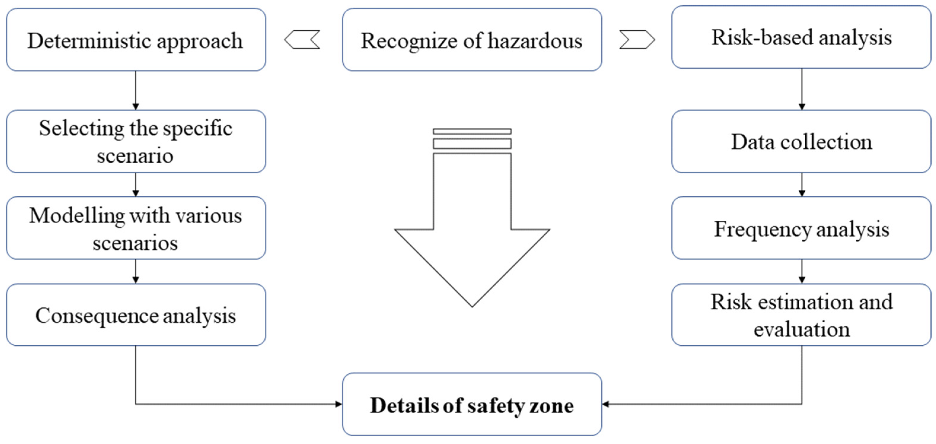
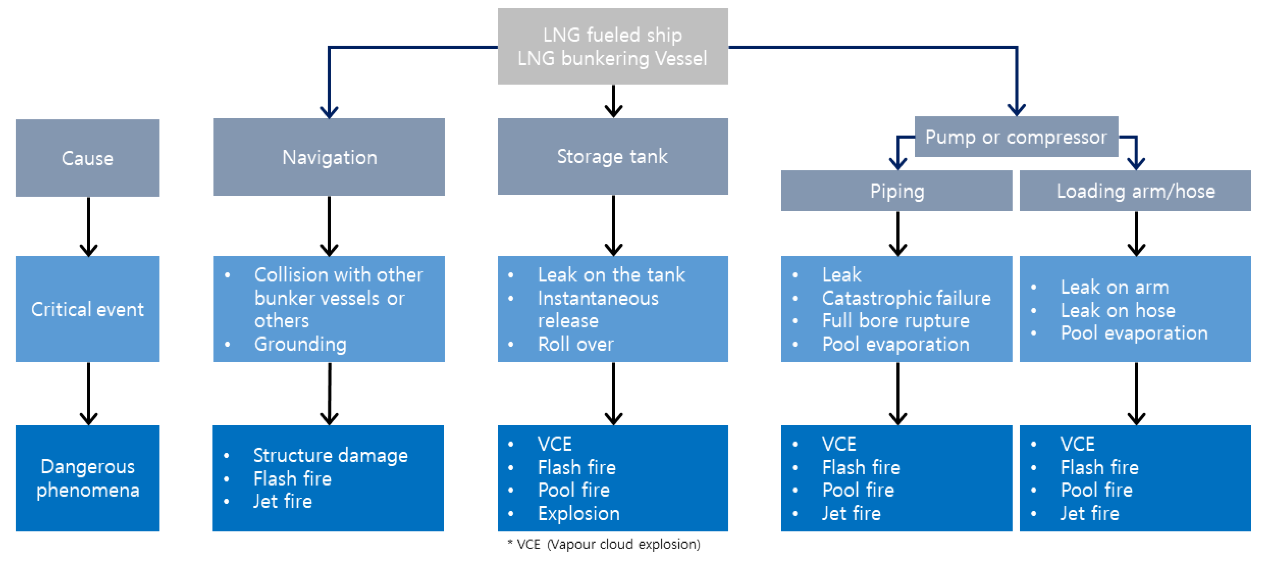
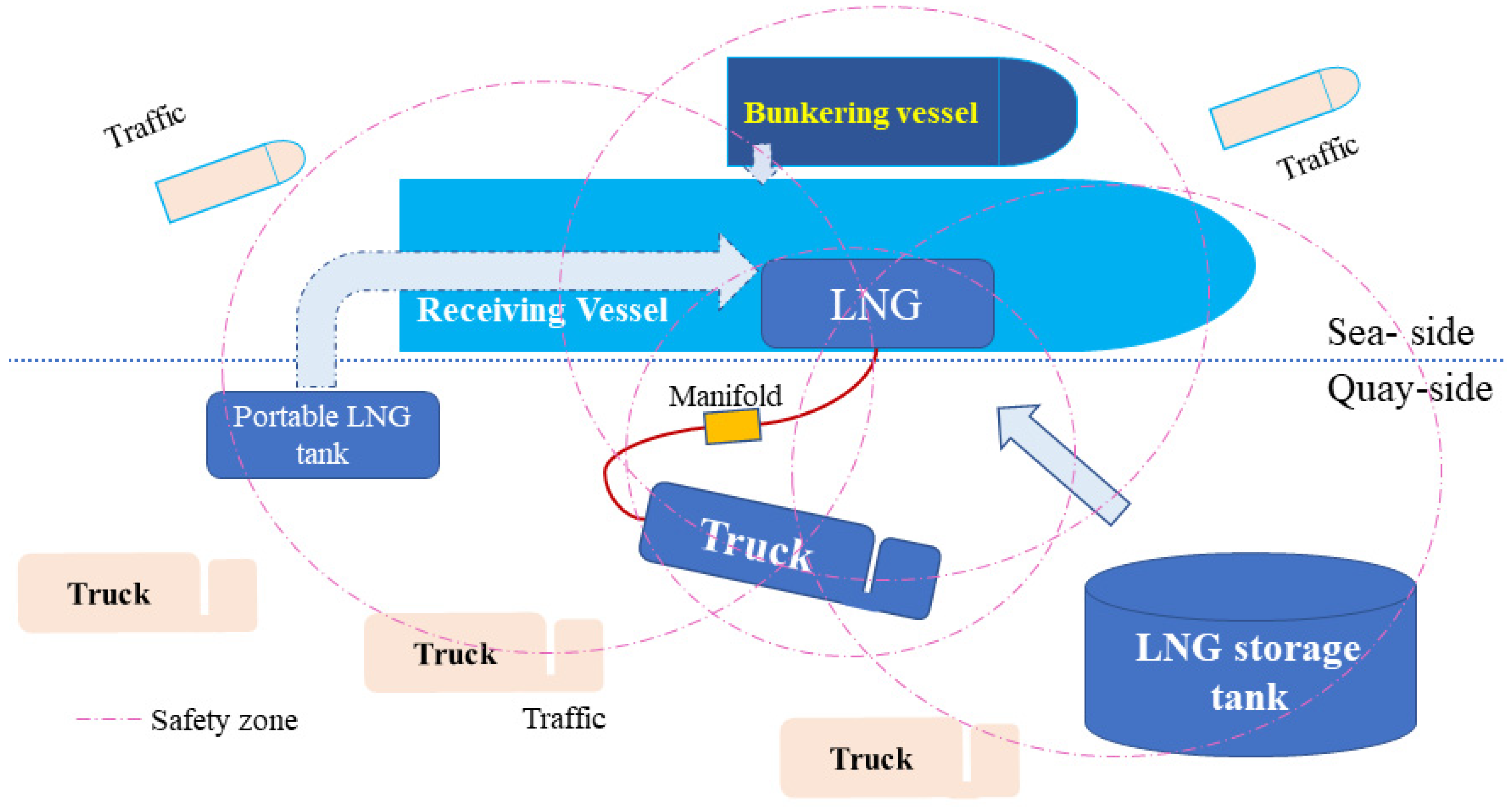
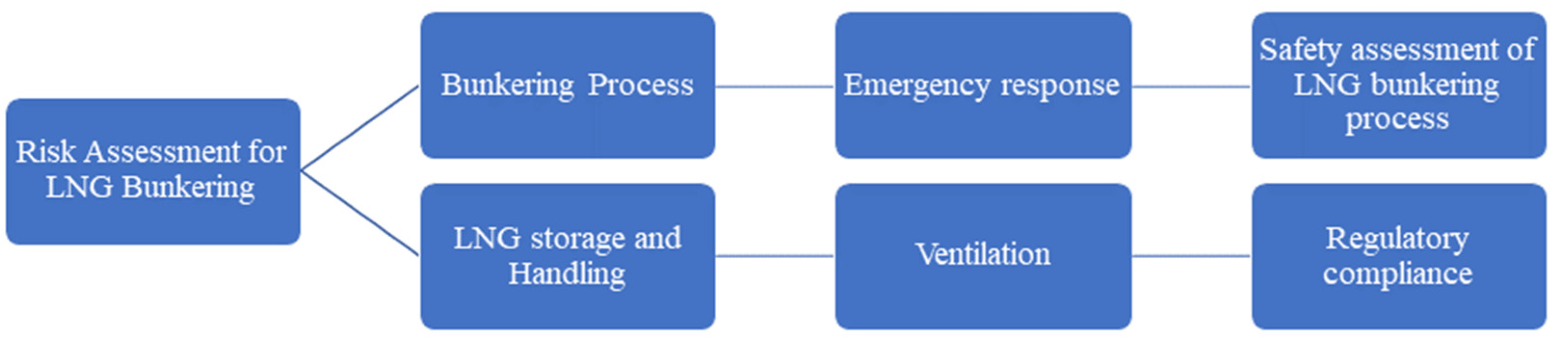
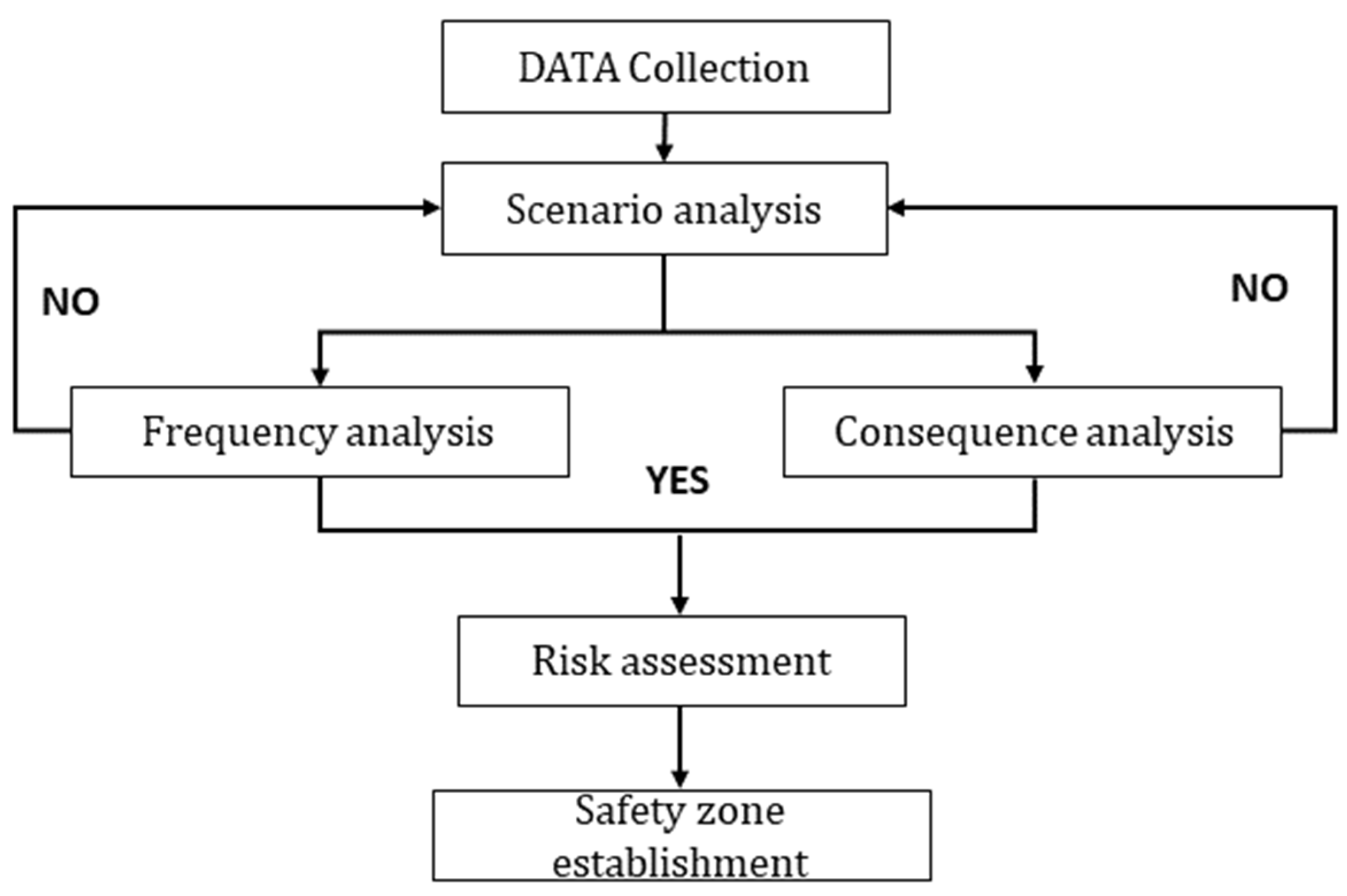
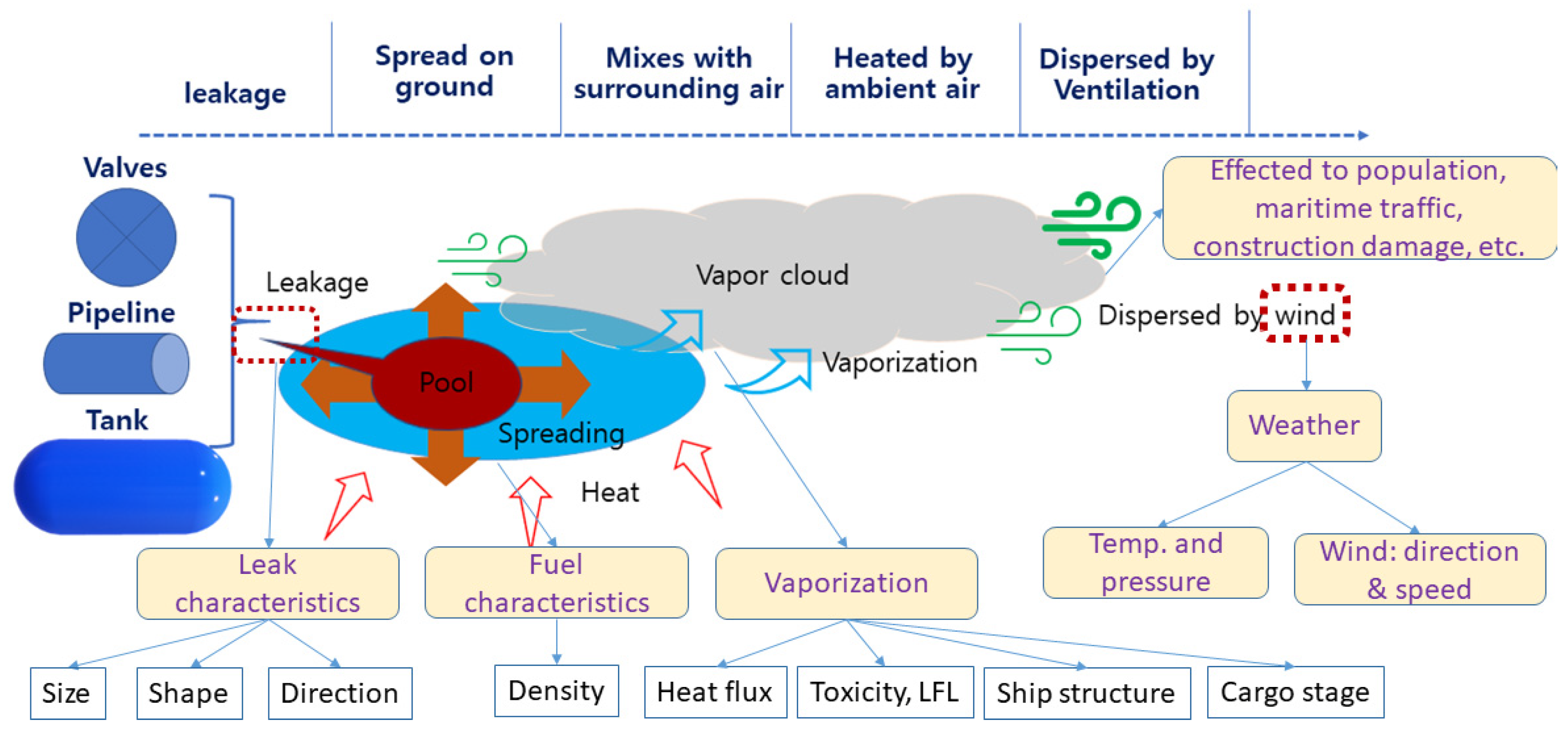
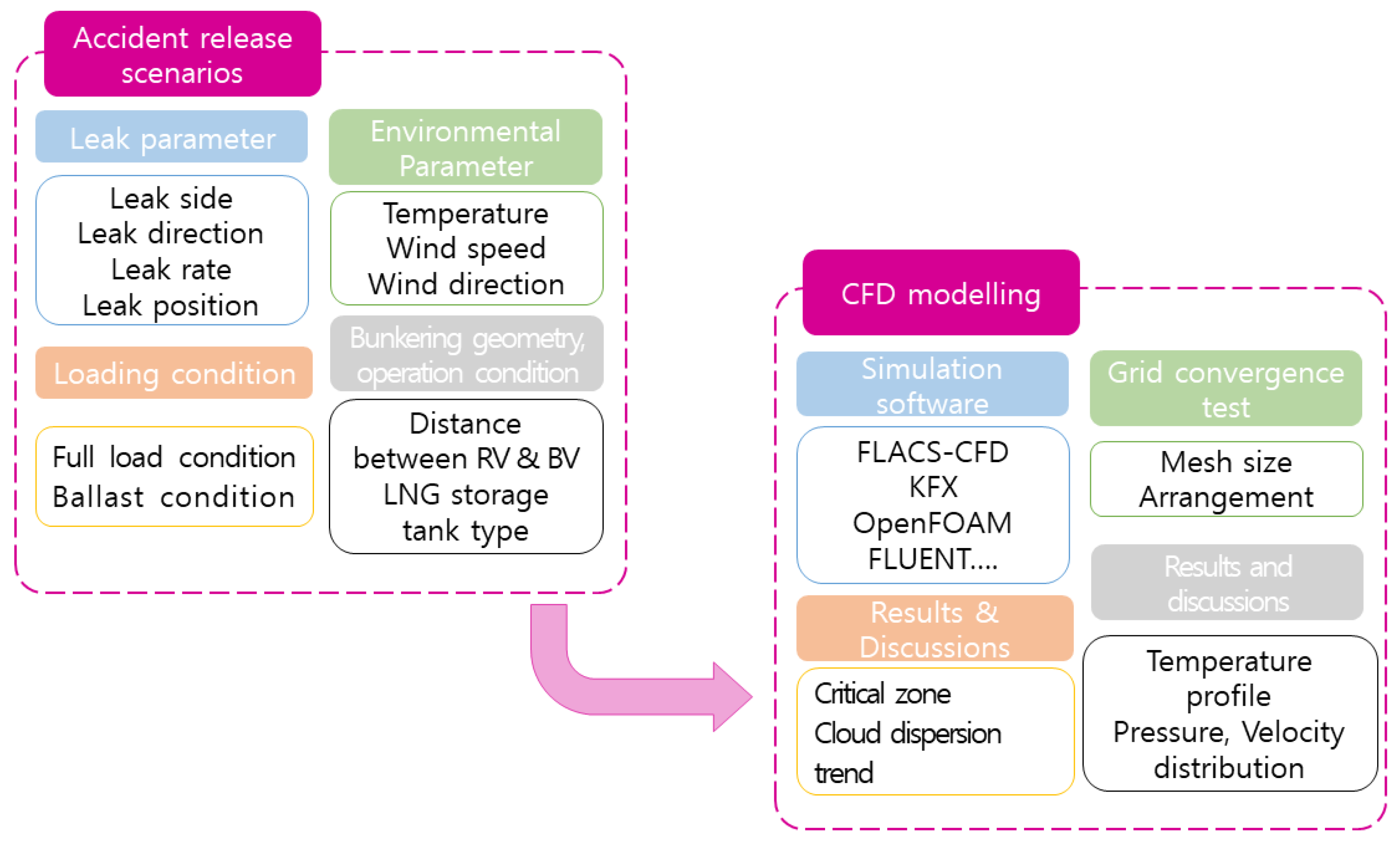
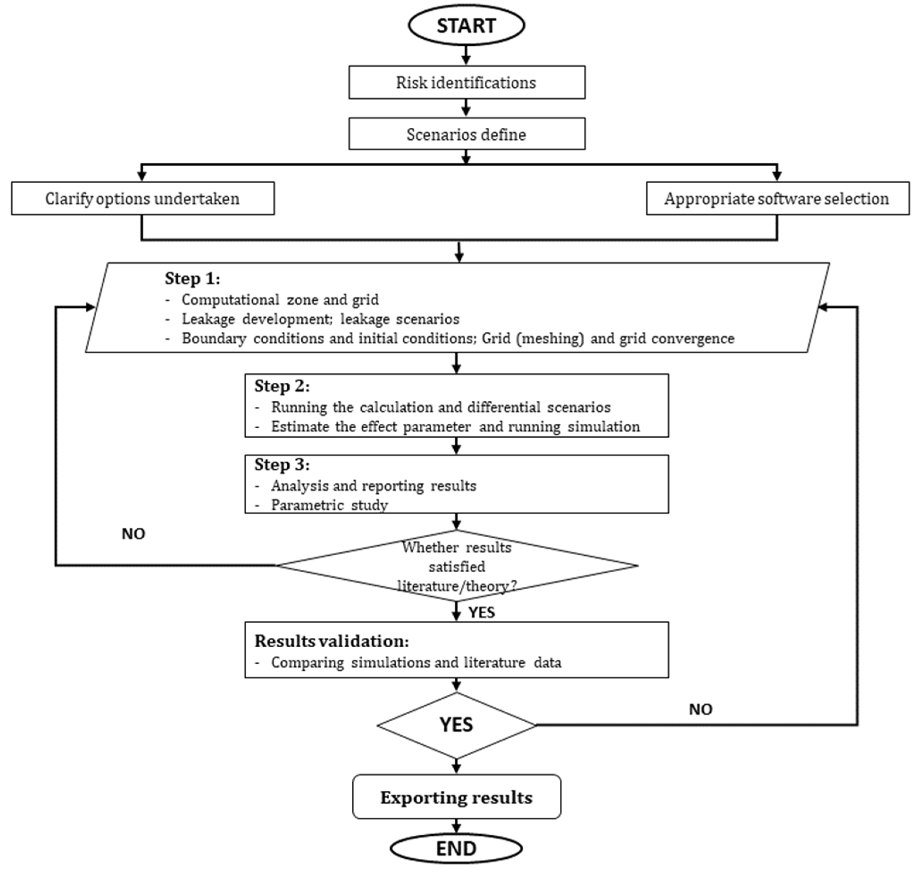
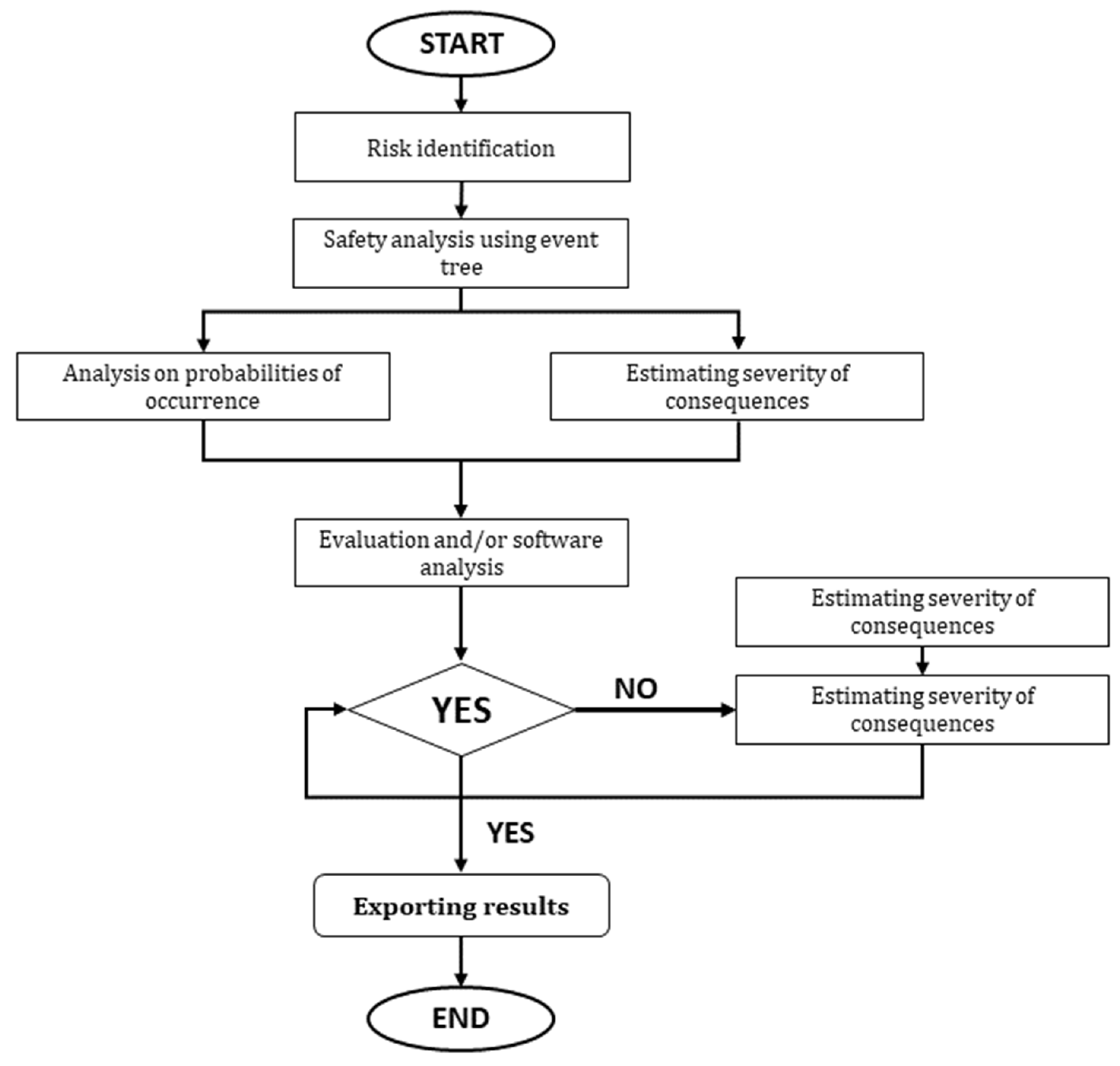
Table 1.
Basic properties of LNG.
| Properties | Unit | Value |
|---|---|---|
| Boiling point | °C | −162 (−259 F) |
| Flash point | °C | <−188 (−306 F) |
| Evaporation rate (n-butyl acetate = 1) | >1 | |
| Flammable limit [39,40] | volume % in air | 5–15 |
| Vapor pressure (at −110 F) | psia | 700 |
| Vapor density (at 14.7 psia and 60 F) | lb/ft3 | 0.0435–0.0481 |
| Liquid density (at −260 F (H2O = 8.33 lbs/gallon) at 60 F) | lbs/gallon | 3.5–4.0 |
| Relative density/specific gravity (at −260 F (H2O = 1)) | 0.43 | |
| Auto-ignition temperature: | °C | 537 (999 F) |
| Stored pressure | psia | atmospheric |
| Behavior if spilled | When it evaporates, it forms visible clouds, some of which might become flammable or explosive under specific circumstances if they are confined. | |
Table 2.
LNG incident records [48].
Table 2.
LNG incident records [48].
| Reference | Time | Place | Accident Description | Results |
|---|---|---|---|---|
| [49] | 1965 | Canvey Island, UK | While conducting an LNG transfer, an unfortunate mishap occurred, leading to the unintended release of LNG. This release subsequently ignited, resulting in severe injuries to an individual. | One reported injury involved a severe burn. |
| [50] | 1979 | Columbia Gas LNG Terminal Cove Point, Maryland | LNG seeped through the electrical penetration seal of the LNG pump, infiltrating the substation. A circuit breaker then triggered the ignition of the natural gas–air mixture, leading to a powerful explosion. | One fatality and one individual with severe injuries have been reported. |
| [51] | 2006 | Port Fortin, Trinidad, Caracas | Atlantic LNG has reported an incident at its Train 2 facility in Point Fortin, Trinidad. This unfortunate occurrence was triggered when a temporary eight-inch isolation plug succumbed to mounting pressure. The release of natural gas was successfully managed, and personnel were able to resume their duties. | A single injury has been reported. |
| [52] | 2007 | Shanghai, China | A physical explosion was caused in the testing of an LNG tank. | An explosion resulting from a tank pressure test claimed the life of 1 individual and left 16 others with injuries. |
| [48] | 2010 | Montoir de Bretagne Terminal, France | The incident transpired when liquid infiltrated the gas take-off line while the discharge operations were underway. As a consequence of this occurrence, damage extended to a portion of the ship’s manifold and its associated feed lines. | |
| [48] | 2011 | Yung An LNG Terminal, Taiwan | The vessel’s captain made the decision to temporarily halt the discharge process and relocate the ship away from the berth. Fortunately, the issues were subsequently resolved, allowing the vessel to return and successfully complete the discharge of its cargo. | No injuries have been recorded, but there was structural damage. |
| [48] | 2011 | Pyeongtaek LNG terminal, Korea | The vessel disengaged from the berth following the discovery of a minor LNG leak near the top of one of the emergency release couplers, shortly after the completion of a planned overhaul of the unloading arms. Subsequently, new seals and ball valves were installed on the unloading arms, allowing the resumption of the discharge process with the two remaining arms. | No injuries have been recorded, but there was structural damage. |
Table 3.
Regulatory framework for marine LNG bunkering.
| Organization | Content |
|---|---|
| IGC Code | The IGC Code is applicable to gas carriers built on or after 1 July 1986. Gas carriers constructed prior to this date are also obligated to adhere to the stipulations outlined in either the IGC code or the EGC Code, both of which have been promulgated by the IMO. These codes have the aim of setting up a universally accepted standard for the safe shipping of liquefied gases and specific other substances in bulk via maritime transport. It achieves this by specifying the design and construction criteria for ships involved in such transport and delineating the necessary equipment they must carry. This framework is aimed at minimizing risks to the vessels, their crews, and the environment, taking into consideration the characteristics of the transported products. |
| IGF Code | The primary objective of the IGF Code is to establish a universal standard for vessels, distinct from those governed by the IGC Code, that utilize gas, such as LNG, or low-flashpoint liquids as their propulsion fuels. This Code mandates specific directives related to the arrangement and installation of machinery, equipment, and systems on vessels utilizing gas or low-flashpoint liquids as fuel. These guidelines are tailored to the specific characteristics of these fuels. Recreational vessels (RVs) are obligated to adhere to the stipulations of the IGF Code, or, alternatively, conform to the requirements stipulated in the IGC Code if they fall within the category of gas carriers as defined by the IGC Code. |
| STCW | The International Convention on Standards of Training, Certification, and Watchkeeping (STCW) for seafarers, established in 1978, defines the minimal qualification standards for masters, officers, and watch personnel serving on seagoing merchant vessels and large yachts that fall under the jurisdiction of the IMO regulations. On the 11 June 2015, the IMO Resolution MSC.396(95) was enacted to amend the STCW 1978 Convention. This amendment introduced prerequisites for individuals working on ships subject to the IMO IGF Code, encompassing gas-fueled vessels. These requisites are applicable to ship personnel involved in all forms of LNG bunkering operations, including STS, TTS, and PTS bunkering operations. Within the STCW framework, Chapter V specifically addresses “Special training requirements for personnel on certain types of ships”, with gas-fueled ships falling into this category. STCW Regulation V/3 within Chapter V delineates the minimum training and qualification criteria for seafarers on ships governed by the IGF Code. Moreover, STCW Code Section A-V/3 of Chapter V outlines the details of Basic Training (as found in Table A-V/3-1) and Advanced Training (as outlined in Table A-V/3-2), including the specified standard of competencies required. |
| ISM Code | The purpose of this Code is to set forth a global standard governing the safe administration and functioning of ships while emphasizing pollution prevention. Ensuring the secure management and operation of ships is an integral facet, with particular emphasis on averting harm to the environment, with a primary focus on the marine ecosystem and property protection. The Code establishes safety management objectives for companies overseeing ship operations, with the primary goal of achieving the following:
|
| Rules from members of the IACS | The members of the IACS promulgate regulations and standards pertaining to the classification of vessels engaged in the transportation of liquefied gases in bulk, as well as vessels utilizing gases or low-flashpoint fuels. The IACS has formally integrated the stipulations outlined in the IGC Code and the IGF Code for the respective categories of ships. Consequently, RVs, liquefied gas bulk carriers (LBBs), and liquefied gas bulk vessels (LBVs) constructed in compliance with the IACS Rules will, in most cases, conform to the relevant requirements specified in the IGC and/or IGF Codes. |
| IACS Rec. 142 | In June 2016, the IACS unveiled its LNG Bunkering Guidelines, developed through a collaborative effort involving a working group comprised of experts selected from various member organizations within the IACS. These guidelines from the IACS play a crucial role in assembling LNG Bunker Management Plans, defining the roles and corresponding accountability and responsibility of key personnel, and offering recommendations regarding the bunkering process, simultaneous operations (SIMOPS), safety zones, and risk assessments. Additionally, the guidelines incorporate technical requirements for bunkering systems. It is worth highlighting that IACS Recommendation 142 (IACS Rec 142) is not merely referenced but is also seamlessly integrated into the SGMF LNG Bunkering Guidelines. This integration is facilitated by the substantial overlap between IACS members and SGMF members, with many actively participating in the working groups responsible for generating the SGMF’s publications. |
| EMSA | The European Maritime Safety Agency (EMSA) has produced an extensively detailed document titled “Guidance on LNG Bunkering for Port Authorities and Administrations”. This document provides a wealth of information on optimal control measures for LNG bunkering and small-scale LNG storage. It is particularly relevant for port authorities and administrations, given their responsibilities encompassing permitting, assessment, approval, certification, oversight, documentation, and emergency response coordination. The most recent edition of this guidance document, dated 31 January 2018, offers comprehensive instructions, with a primary emphasis on small-scale LNG bunkering. Widely recognized as an invaluable resource for all ports, the document includes a dedicated section on port infrastructure and addresses floating storage units (FSUs) as well. Esteemed within the maritime industry, this guidance document holds significance as one of the most comprehensive publications issued by a safety agency. It has gained recognition as a standard reference for all stakeholders involved in the LNG supply chain, frequently cross-referencing pertinent sections to provide additional value. |
| SGMF | The SGMF has published a series of pertinent documents, crafted in close collaboration with global maritime stakeholders within the gas supply chain. These publications incorporate the collective expertise of SGMF members, focusing particularly on operations involving gas, including natural gas and LNG. These publications encompass recommendations for best practices in several critical areas, including:
|
| IAPH | The International Association of Ports and Harbors (IAPH) positions itself as the “Global voice for the Ports of the world”, providing ports worldwide with a platform for global representation. Established on 7 November 1955, during a meeting in Los Angeles, the IAPH originated with approximately 100 delegates from 38 ports and maritime organizations across 14 countries. Over the past six decades, it has transformed into a global coalition of ports, now boasting around 180 member ports and approximately 140 port-related businesses situated in 90 countries. Together, these member ports oversee more than 60% of the world’s maritime trade and almost 80% of global container traffic. Functioning as a non-profit and non-governmental organization (NGO), the IAPH is headquartered in Tokyo, Japan, and holds the unique distinction of being the sole international body representing the voice of the global port industry. The IAPH has been granted Consultative Status as an NGO by five specialized agencies of the United Nations (UN) and one intergovernmental body. This consultative status empowers the IAPH to express the perspectives of port managers and directors at international forums and advocate for the collective interests of the global port industry. The core mission of the IAPH centers around promoting the worldwide interests of ports, fostering strong relationships among its members, and facilitating the exchange of best practices among its constituents. |
| Lloyd’s Register [58] | The purpose of this guideline is to provide port authorities with thorough and relevant information to convey a comprehensive understanding of the characteristics of LNG as a marine fuel product. This information includes details about associated equipment and delivery mechanisms, potential hazards, authorized zones, and strategies for risk mitigation. Furthermore, the guideline clarifies the roles and responsibilities of the various stakeholders involved in LNG supply operations and emphasizes the significance of training for personnel engaged in these operations. |
| Korean Register [59] | This set of guidelines pertains to the utilization of low-flashpoint fuels in maritime vessels. It also outlines the overarching safety prerequisites for employing these fuels on board ships. |
Table 4.
Research on risks assessment of LNG release.
| Author(s) | Approach | Method | Bunkering Focus | Main Contribution |
|---|---|---|---|---|
| Duong et al. [79] | Deterministic | FLACS-CFD | Ship to ship | Examines the properties of leak dispersion and ascertains the safety distance involved in ship-to-ship LNG bunkering. Key factors in this investigation include prevailing weather conditions, such as wind speed and direction, as well as the specific attributes of the leak, encompassing its rate and duration. |
| Jeong et al. [80] | Probabilistic | Frequency analysis | Ship to ship | The safety zone is calculated at 541.8 m for 1 × 10⁻⁶ year and 80.4 m for 1 × 10⁻⁵ year and 34.9 m for 1 × 10⁻⁴. |
| Carboni et al. [81] | Deterministic | Phast | Truck to ship | Various configurations typical of marine vessels, along with alternative operational scenarios, were subject to analysis using three-dimensional computational fluid dynamics models. These models incorporated sub-models tailored for cryogenic conditions. The resulting distribution of the cryogenic fuel was then utilized to assess the safety perimeter concerning the risk of a flash fire. Furthermore, the interplay of temperature distribution and wind speed was employed to identify the region that might be susceptible to frostbite. |
| Park et al. [82] | Hybrid (semi-quantitative) | Frequency analysis + Phast | Terminal to ship | The objective of the study is to formulate an enhanced and more pragmatic layout for the safety zone, specifically focusing on the evaluation of the probability and consequences of leaks associated with LNG bunkering. Drawing inspiration from the principles of offshore QRA methodologies, this approach considers various leak scenarios, each with its respective probabilities, and integrates these scenarios to create a comprehensive design for the safety zone. |
| Sun et al. [83] | Deterministic | Ansys Fluent 16.0 | Ship to ship | The study seeks to characterize various hazards, assess the extent of potential danger zones, and explore potential mitigation strategies employing computational fluid dynamics. In this context, a water curtain, commonly employed to avert material stress cracking in the event of LNG leakage, was duly examined as a suitable means to mitigate the radiation hazard. |
| Zhu et al. [84] | Deterministic | Dynamics model + simulation | Leakage accident of a 2500 m3 storage tank | Initially, a model for the inadvertent release and dispersion of LNG was developed, which involved an analysis of the fundamental principles governing such releases. Subsequently, a mathematical model was employed to simulate the calculations related to a leakage incident in a tank situated within an LNG storage and distribution facility. This was performed to foresee and assess the potential outcomes of a leakage accident. |
| Luo et al. [85] | Deterministic | Fluent 15.0 | Falcon-1 and Burro-8 test | The results suggest that the existence of the impoundment plays a crucial role in mitigating the dispersion of the vapor cloud, especially in the lateral direction and, to a slightly lesser extent, in the downwind direction. It is noteworthy that the vertical dispersion of the vapor cloud is influenced by the vortex created by the impoundment and billboard structures. |
| Jeong et al. [86] | Probabilistic | Frequency analysis | 300,000 DWT LNG fueled vessels | The examination encompassed the current guidelines and regulatory structures concerning safety procedures in fuel preparation facilities. The evaluation indicates a significantly increased risk of explosions in the high-pressure FGSS, with an estimated annual frequency reaching as high as 3.13 × 10⁻⁴. It is crucial to acknowledge that an explosion within the fuel preparation rooms could lead to stress levels surpassing permissible thresholds in structural components, particularly the bottom structure, unless adequate reinforcement measures are put in place. |
| Giannissi et al. [87] | Deterministic (quantitative risk assessment) | ADREA-HF code | Falcon Series experiments | In the scenario involving the two-phase jet, the model exhibits a more favorable overall correspondence with the experimental data, although it tends to underestimate the peak concentrations observed. Conversely, in the case of a constant area vapor pool, the model typically yields lower concentration estimations and overestimates the time it takes for the substances to reach a given location. |
| Sultana et al. [88] | Probabilistic | HAZOP and STPA | Ship-to-ship bunkering | A comparative assessment was conducted to examine the potential substitution of HAZOP analysis with STPA, utilizing a case study focused on the STS transfer process of LNG. The outcomes of this investigation indicate that STPA and HAZOP can function as complementary methodologies rather than direct replacements. It is essential to underscore that this conclusion is drawn solely from the results of a specific case study related to LNG STS transfers. To validate these findings, further scrutiny involving diverse process applications is imperative. |
Table 5.
Experimental study on LNG leakage.
| Author(s) | Category | Experimental Targets | Facility | Main Contribution |
|---|---|---|---|---|
| Zhang et al. [97] | Controlled experiment | The main objective of this study was to achieve a thorough comprehension of the dynamic patterns of underwater-released LNG jets and to scrutinize the correlated vapor dispersion and combustion traits at the water surface across various release scenarios. | A high-speed camera was employed to record the dynamic sequence of LNG being jet released through orifices of varying sizes and shapes, along with the formation of the rising plume structure. Additionally, a flow meter and pressure gauge were utilized to measure and document the leakage flow rate and pipeline pressure, respectively. | As the orifice size was enlarged, the LNG leakage flow rate increased, accompanied by a decrease in pipeline pressure. The underwater release of LNG through a jet was observed to undergo four distinct stages: the initial liquid jet phase, the formation of liquid droplets, the ascent and vaporization of these droplets, and the subsequent rise and heating of the vapor phase. When compared to a circular orifice with a similar area and Reynolds number (Re), the release of LNG through a rectangular orifice led to a broader plume angle. |
| Gopalaswami et al. [98] | Experiment and CFD modelling | An examination of the phenomenon pertaining to the spreading and vaporization of a pool | The experimental procedure was conducted within an L-shaped trench situated at BFTF. This trench comprised two sections, namely, leg 1 and leg 2, each measuring 8.2 m in length, 1.22 m in width, and 1.05 m in depth. | The interplay of wind exerted a discernible impact on both the processes of pool spreading and vaporization, primarily through the mechanisms of entrainment and convection. When the wind blows counter to the direction of the pool, it effectively retards the spreading phenomenon to a considerable degree. Additionally, the wind plays a role in modifying the vaporization process by introducing supplementary heat and desaturation, accomplished through the mechanism of entrainment. |
| Cleaver et al. [99] | Experiment | LNG release from pipework | LNG was released from a pipeline with a diameter of 75 mm and 70 bars of pressure. | The analysis was made with vapor cloud dispersion, LNG pool fires, and rapid phase transitions. |
| Zhu et al. [100] | Experiment and simulation | Experimented on 1.4 t LNG leakage and release | Pool scale at 5 × 3 × 1.2 (m) in an open environment | In the experimental analysis, the highest observed methane concentration reached 4.1%, while the simulation yielded a slightly higher maximum concentration of 4.6%. These findings demonstrate a favorable alignment with the deviation statistics, as they fall within the range recommended as standard. |
| Suardin et al. [101] | Experiment at Texas A&M University | Effectiveness of expansion foam to reduce pool fires of LNG and fire characteristics of LNG | 65 m2 of LNG pool fire and a wind speech of 2.2 m/s | The placement of foam generators near larger pits and considering the prevailing wind direction is crucial, especially when dealing with significant and highly radiant flames. These flames can pose a risk of damaging the foam generators, rendering them ineffective unless specifically designed and thoroughly tested to withstand such demanding conditions. An efficient approach could involve arranging a series of foam generators, aiming to minimize the distance foam needs to cover, reduce the time for foam to reach its target area, and accelerate the achievement of the desired foam depth. |
| Qi et al. [102] | Experiment | The phenomenon of LNG release under water In-air dispersion behavior of LNG | Pit dimensions of 10.06 × 6.4 × 1.22 (m), vertical jet release | The temperature recorded for the vapor rising from the water surface reached a minimum of −1 °C, signifying that the vapor released into the atmosphere exhibited buoyancy. In a broader context, the highest concentration of vapor observed at each monitoring point ascended to increasingly greater elevations as one moved in the downwind direction, signifying an upward movement of the vapor cloud. These observations, as corroborated by the visual records of the “white” cloud ascending nearly vertically in the air, align with the data collected by the instruments. It is important to note that no visible LNG pool was discernible on the water surface. |
| Cai et al. [93] | Experiment and numerical study | Examination of flame structure, the law of distribution of the leakage gas, and dispersion trends | The experiment field with size of 2 × 4 × 2.6 (m) in open area | The overall trend in the dispersion of the natural gas volume fraction reveals an increase in volume fraction with higher elevations. Moreover, locations at the same elevation experience a higher volume fraction when closer to the source of the leak. In particular, among different leak scenarios, the natural gas volume fraction reaches its peak when the leak originates from the hose. It is noteworthy that the arrangement of the kitchen packaging material significantly impacts the dispersion pattern of natural gas. |
Disclaimer/Publisher’s Note: The statements, opinions and data contained in all publications are solely those of the individual author(s) and contributor(s) and not of MDPI and/or the editor(s). MDPI and/or the editor(s) disclaim responsibility for any injury to people or property resulting from any ideas, methods, instructions or products referred to in the content. |
© 2024 by the authors. Licensee MDPI, Basel, Switzerland. This article is an open access article distributed under the terms and conditions of the Creative Commons Attribution (CC BY) license (https://creativecommons.org/licenses/by/4.0/).
Share and Cite
MDPI and ACS Style
Duong, P.A.; Ryu, B.R.; Jung, J.; Kang, H. A Comprehensive Review of the Establishment of Safety Zones and Quantitative Risk Analysis during Ship-to-Ship LNG Bunkering. Energies 2024, 17, 512. https://doi.org/10.3390/en17020512
AMA Style
Duong PA, Ryu BR, Jung J, Kang H. A Comprehensive Review of the Establishment of Safety Zones and Quantitative Risk Analysis during Ship-to-Ship LNG Bunkering. Energies. 2024; 17(2):512. https://doi.org/10.3390/en17020512
Chicago/Turabian StyleDuong, Phan Anh, Bo Rim Ryu, Jinwon Jung, and Hokeun Kang. 2024. "A Comprehensive Review of the Establishment of Safety Zones and Quantitative Risk Analysis during Ship-to-Ship LNG Bunkering" Energies 17, no. 2: 512. https://doi.org/10.3390/en17020512
Note that from the first issue of 2016, this journal uses article numbers instead of page numbers. See further details here.