
A Distributed Control Scheme for Cyber-Physical DC Microgrid Systems
by
 , , , and
Adeniyi K. Onaolapo
1,
Gulshan Sharma
1,
Pitshou N. Bokoro
1,
Anuoluwapo Aluko
2 and
Giovanni Pau
3,*
1
Department of Electrical Engineering Technology, The University of Johannesburg, Johannesburg P.O. Box 524, South Africa
2
Department of Electrical and Software Engineering, University of Calgary, Calgary, AB T2N 1N4, Canada
3
Faculty of Engineering and Architecture, Kore University of Enna, 94100 Enna, Italy
*
Author to whom correspondence should be addressed.
Energies 2023, 16(15), 5611; https://doi.org/10.3390/en16155611
Submission received: 5 July 2023
/
Revised: 18 July 2023
/
Accepted: 24 July 2023
/
Published: 25 July 2023
(This article belongs to the Section A1: Smart Grids and Microgrids)
Abstract
:An innovative distributed secondary control technique for balanced current sharing and voltage regulation for an off-grid DC microgrid setup is presented in this research. The droop control scheme is conventionally used for current sharing amongst distributed sources (DSs) in a microgrid. However, this method has two major drawbacks. Firstly, due to the line resistance of each DS, the output voltage is different for each DS, and the output current-sharing property deteriorates. Secondly, the droop action increases the DC bus voltage variation. To address these drawbacks, a fuzzy-based distributed secondary controller is proposed. The proposed controller in each DS simultaneously ensures balanced current sharing and sustains DC bus voltage at the reference value by using a communication network to interact with one another. The required circumstance to guarantee the proposed controller’s stability is provided. The stability analysis is beneficial to inform the choice of control parameters. The real-time simulation outputs demonstrate the proposed control scheme’s robustness in achieving the control objectives under varying operating conditions.
1. Introduction
Significant advancements in the field of communication, computing, and control have played a major part in the recent developments of cyber-physical systems (CPSs) in different industries such as energy, health, production, transportation, etc. The CPS integrates the cyber system to monitor and control a physical process in a safe, stable, and secure way using real-time communication and feedback control. The cyber system uses 3C technology (communication, computation, and control) with a feedback loop to the physical system [1,2,3]. Modern power systems in the direction of “smart grids” have harnessed the advancement in CPSs in the power systems industry. Sensors, actuators, controllers, and communication networks are features that ascertain the efficient, unfailing, and safe performance of energy systems. Thus, smart grids reflect the characteristics of a CPS [4,5].
In today’s smart grids, microgrids () are considered CPSs that use advanced 3C technologies to increase the renewable energy systems’ integration into the distribution network of the power system to improve the operational efficiency, performance, and resilience of the network. are small electricity generation entities that combine energy storage systems, distributed generators, and loads usually operated in the stand-alone or grid-connected mode [6,7,8,9,10,11,12]. They have AC, DC, or hybrid topology. While the AC has been extensively studied, the DC has gained appreciable interest in the last decade due to its advantages such as reduced complexity (fewer power electronics devices), uncomplicated control scheme (no frequency and reactive power control), and higher efficiency (reduced power conversion stages) [13,14,15,16]. Generally, use a hierarchical control form (primary—, secondary—, and tertiary) to ensure a continuous and safe operation. The DC , as a CPS, must execute numerous real-time control operations, including voltage control, balanced power sharing, proportional power distribution, energy management, and cost optimization [17,18,19,20].
In stand-alone DC , which is the focus of this work, where more than one distributed generator, storage systems, and loads are linked to the DC bus, the control system’s goal is to normalize the voltage of the DC bus and ensure proportional current sharing between the power sources. Several and control techniques have been posited to realize these objectives. The earliest control scheme uses the virtual resistance or droop control technique applied in the control loop of the power sources in the DC system. The ratio of the current sharing between the sources is determined by the magnitude of the droop resistance, which can be static or time-varying [21]. In [22], the circulating current between converters of the distributed generators as a result of the traditional droop control is used to build a modified droop control scheme to increase the effectiveness of the traditional droop control technique. In [23], voltage regulation is achieved locally using the DC bus signaling technique for independent and coordinated control of multiple storage systems without using a communication system in the DC . The coordinated control is implemented by allowing the state-of-charge limits of the battery systems in the setup. In [24], an improved droop control using a communication link to exchange output current and voltage information among the converters is proposed. However, this control strategy may necessitate a sophisticated communication setup between the network’s nodes to transmit the local voltage and current signals between the distributed generator controllers in the , increasing the communication infrastructure cost [15]. In [25], the decentralized composite controller is proposed by combining voltage and droop control methods to sustain the voltage of the DC bus at the specified value in the . While the major advantage of droop control is the absence of communication links between the converters, which reduces the complexity of the setup, it has the drawback of large DC bus voltage deviation when large values of droop resistance are selected, and the line impedance between the sources and load is high. That is, the droop control ensures the distributed generators’ current sharing but largely impacts the DC bus voltage. In [26], a multiport DC-DC converter was developed for DC microgrid implementation. The control scheme was proposed for renewable sources’ power control strategies, such as PV maximum power point tracking (MPPT). The configuration of the scheme has a key feature that allows for full control of DC link voltage irrespective of the PV resource available. A consensus-based controller with a DC microgrid’s cascaded multiport converter and the PV for a hybrid energy storage system (HESS) was presented in [27] using a hardware-in-loop (HIL) setup. The two stages of the cascaded multiport converter are made up of the supercapacitor and the batteries, respectively. For the long lifespan of HESS, the multiple batteries’ state-of-charge (SOC) imbalance is solved using the developed consensus-based controller, which equalizes the SOCs among multiple batteries. Plug-and-play operations are enabled in the consensus-based controller, accommodating different numbers of batteries. A probability-density-based load frequency controller was developed in [28]. The authors applied the concepts of deception attacks and random transmission delays of multiarea network circuits and the decentralized secure load frequency control. Two distributed delay terms were formed from the injected deceptive attack signal and the normal control signal transmitted over the network. Then, the distributed kernel, which is the delay probability density, was established from the ith load frequency control area. The controller design guaranteeing the system stability was then derived from kernel-based integral inequality with given performance. A fuzzy load frequency controller (LFC), which is sample memory-event-based, using transmission delays and measurement outliers, was proposed for wind power systems (WPSs) in [29]. Transmission delay was used to represent memory signal as a distributed delay term that varies with time, thereby building up a T–S fuzzy time-varying distributed delay system and modeling the LFC WPS. Criteria were then derived to solve the fuzzy control and the triggering matrix using the distributed delay-based integral inequality and the Lyapunov method. Low-power applications, such as multiple-input, multiple-output (MIMO) isolated converters, were developed for residential DC nanogrids in [30]. The structure enables flexible power flow control by minimizing the number of power conversion stages and operating as a power interface using a DC-DC multiwinding multidirectional flyback converter. A port uses phase-shift control or duty cycle control to absorb or supply energy due to its multidirectional features. The power flow among the ports is then managed by a predictive controller using the decoupling of the operating modes of the converter.
To concurrently achieve voltage regulation and current sharing in the DC , the control is introduced. The objective of the control technique of the DC is to sustain the voltage at the DC bus within specified limits while confirming the appropriate current sharing between distributed generators. The control uses a communication network to provide real-time control actions in the cyber-physical DC . The control can be distributed, decentralized, or centralized. In the central control of the DC , a voltage controller normalizes the bus voltage by producing an appropriate voltage reference and sending it to the distributed generators. The voltage reference offsets the voltage variation due to the droop in the local control of each distributed generator [31,32,33]. The shortcomings of the centralized secondary control in the DC are its vulnerability to single-point failure, lack of plug-and-play capability, and slow response to changing loads [34].
In addressing the problems that arise with centralized control, distributed control is developed. In the distributed control method, each distributed generator is equipped with a controller. It exploits characteristics of a typical CPS by using the peer-to-peer communication network to exchange information and control signals in real time to attain voltage regulation and current-sharing goals in the [35,36,37]. The distributed control technique posited in [38] adopts two proportional–integral controllers for independent proportional current sharing in the . The disadvantages of this method are the additional computational cost of the two controllers and the increased communication throughput. In [39], a distributed supervisory control is proposed to switch between two independent controllers used for the DC current sharing and voltage regulation, which depends on the value of voltage and current errors. The limitation of this method is the transience generated by the continuous operation of the switching circuit. In [40], a hierarchical control using the master–slave consensus algorithm is posited to mitigate the shortcomings of the control in the DC . The limitation of this method is the lack of plug-and-play ability if the master controller fails. In [41], a distributed control is recommended by combining the current sharing error and voltage as input to the controller in the control layer. The method adopts the pinning gain approach to allow only one controller within the system to have access to the voltage measurement since voltage regulation is a general goal. The limitation of this approach is the effect of latency when switching voltage control between the distributed controllers. In [42], the distributed control is proposed without the droop control in the loop. The recommended control depends on the average current and voltage consensus algorithm with communication delay in the control loop. With the absence of droop in the control loops of the distributed generators, the failure of any of the controllers will exacerbate the voltage and current-sharing deviation in the . In [43], a leader–follower consensus algorithm based on distributed linear multiagent consensus protocol is developed for the control layer of multiple battery energy storage units in DC to achieve balanced power-sharing and voltage control. The limitation of the posited leader–follower algorithm is the large deviation in the voltage of the DC bus when the leader fails.
In order to address the limitations mentioned above, a distributed control technique is proposed in this research that simultaneously regulates the DC bus voltage to the minimal value and ensures balanced current sharing in a stand-alone cyber-physical DC with multiple distributed generators. The distributed control method proposed here uses a peer-to-peer communication network to communicate with neighboring controllers to generate consensus reference signals similar to the centralized control. For practical implementations, the cyber-physical DC and the proposed distributed control strategy are developed in a real-time environment. This research’s contributions are outlined as follows:
- This article proposes a new distributed control technique for balanced voltage regulation and current sharing. The parameters of the proposed controller are adaptively determined using the fuzzy logic control scheme.
- The proposed distributed fuzzy logic control provides a nonlinear mapping between the voltage variation and current sharing error to determine the control reference to realize the control goals. A ramp control signal is presented to reduce the switching transients and ensure steady injection of the control signal.
- The stability assessment of the proposed control technique is conducted using the Lyapunov scheme to provide sufficient design conditions that assure the stability of the proposed controller. The proposed control technique is completely distributed; thus, it could be plugged and played.
The remaining part of this paper is arranged as follows: Section 2 introduces the cyber-physical DC system with the primary control architecture; Section 3 highlights the proposed distributed control and provides sufficient conditions to ascertain the stability of the posited control technique; the outcomes from the simulations of the proposed controller are enumerated in Section 4; and Section 5 expresses the conclusion.
2. Modeling of a Cyber-Physical DC μgrid System
In this section, the cyber-physical DC testbed for the proposed distributed control is developed. The communication system for the distributed control is formulated, and the electrical properties of the physical DC system are modeled with the addition of the individual local controllers to formulate the control goals.
2.1. Cyber System Modeling
The cyber (communication) scheme of the DC is modeled using the peer-to-peer communication (radial) topology. A strongly connected graph can characterize the signal flow between the distributed generators in the , , with the property = {}, where stands for the set of a node of active controllers and represents the set of edges that connect two or more controllers within the , as depicted in Figure 1. The adjacency matrix, , with elements represents information exchanged between nodes i and j. If node i has an active communication link with node j, then , else . Therefore, the information exchange in the DC can be defined by the graph Laplacian matrix where is the in-degree matrix designated as [44].
2.2. Power System Modeling of the DC
Assuming a DC with N distributed generators (), the voltage and current equations for a distributed generator denoted by DGi can be expressed as
where is DC bus voltage, is current of DGi and is the output voltage of DGi, is the line resistance between the DC bus and DGi, and is the jth load connected to the DC bus [21].
2.3. Primary Control in DC
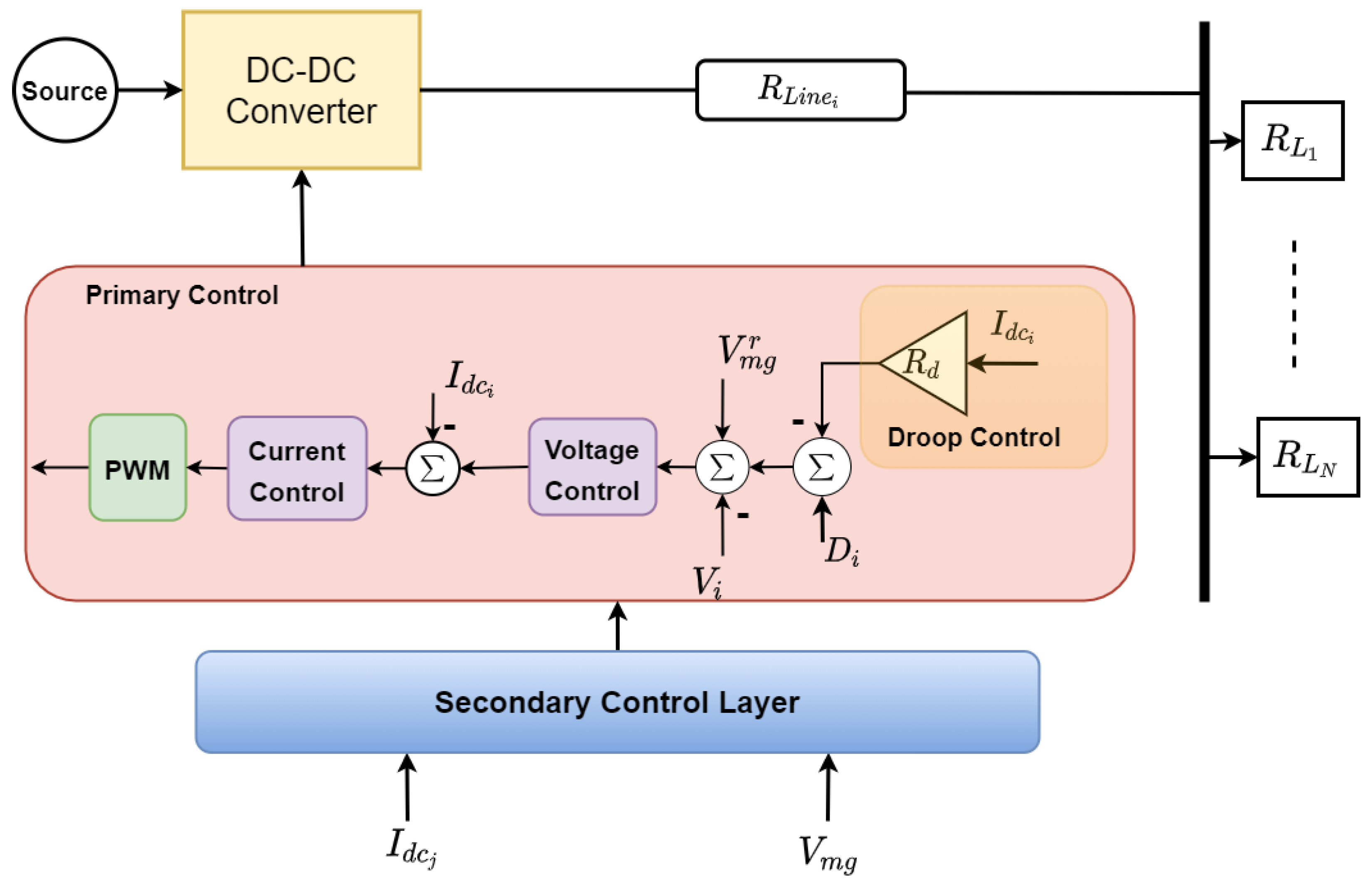
In the local control circuit of the DC-DC converter of DGi in the DC depicted in Figure 1, the current and voltage controllers ensure that the output voltage of the converter trails the reference voltage of the MG. For a DC with N parallel distributed generators linked to a common DC bus, the current sharing is realized by the droop control. The voltage equation of due to the droop control is given by:
where is the global voltage reference of the , is the virtual droop resistance of . From (1), the bus voltage is given by:
For N parallel distributed generators linked to a common bus, the current sharing between and can be deduced from (3) as
It can be inferred from (4) that the current-sharing property is dependent on the droop and line resistance of the individual distributed generator in the DC system. Many studies have simplified their analysis by neglecting the line resistance. However, in practical , the line resistance is not negligible. While the distributed generators’ output voltage should ideally be similar, the droop resistance and line resistance play an integral part in increasing the voltage in regard to the reference voltage of the DC . When a small voltage variation occurs, the circulating current proportionate to the voltage error begins to flow in the DC-DC converter. In this work, the line resistance is included in the problem formulation and assessment of the posited control strategy.
2.4. Problem Formulation and Control Objectives
By considering the conventional droop control described by (2), the droop resistance is typically chosen to be large to guarantee proportional current sharing between the distributed generators, which leads to a voltage deviation , which is expressed as:
Therefore, the foremost control goal is to ascertain DC bus voltage regulation or restoration in the , which can be formulated as:
or can be written alternatively as
Furthermore, to guarantee current sharing between the distributed generators in the DC , a condition described in (4) needs to be met. This is difficult to achieve without leading to significant voltage deviation, and vice versa. Thus, the second control objective to eliminate the current-sharing deviation while maintaining the DC bus voltage is given as:
where
where m is the ratio of the current sharing of the respective distributed generator. Therefore, to ensure voltage restoration and proportional current sharing simultaneously, it is required that the conditions described by (7) and (8) hold. To achieve this, the subsequent section introduces the distributed control scheme for the cyber-physical DC .
3. Proposed Controller Design
As aforementioned, the centralized control has the drawback of single-point failure that degrades the stability and resilience of the . In this research, the distributed control scheme shown in Figure 2 is proposed to return the DC bus voltage to its value of reference and ensure proportional current sharing between distributed generators. In this section, the design architecture of the distributed controller for the DC is presented.
3.1. Distributed Secondary Controller
By considering (3), the voltage of DGi in the DC to realize defined control goals described in (7) and (8) can be expressed as
where is the control input of DGi that can be defined as
where , , and are the distributed control parameters. Setting these parameters to ascertain the voltage regulation and current-sharing goals is complicated and time-wasting because of their effects on the response and stability of the stand-alone DC system [35]. From simple analysis, choosing a large value of leads to a quicker convergence of the DC bus voltage, while setting to a large value leads to a quicker convergence of the current-sharing property. Usually, is selected to be smaller than because the current sharing is a joint goal between the distributed generators. At the same time, voltage regulation is a global goal in the DC . To bypass the design difficulty of these parameters and make the distributed controller more adaptable and flexible for any DC system, the fuzzy logic technique is proposed to adaptively choose the parameter , because it is the scaling parameter between the global voltage regulation and consensus current-sharing objectives in the .
The fuzzy logic scheme is an expert system that uses measurements, long-term experiences, and human knowledge to convert complex and nonlinear control operations into simple fuzzy rules. The general architecture of the fuzzy logic can be divided into three major levels [45]:
- Fuzzification: This transforms physical quantities into fuzzy sets consistent with the predefined membership functions. Linguistic variables are used to represent the membership functions.
- Inference engine: This consists of a database of the membership functions containing its input and output. It also contains the learning basis, which is a set of fuzzy rules that have been mapped using linguistic variables. The fuzzy output of the inference engine is based on the “If-then” mapping of the input fuzzy sets.
- Defuzzification: This transforms the fuzzy outputs into physical quantities that the system of interest can interpret.
For the stability improvement of the control technique by preventing excessive transient overshoot and ensuring smooth activation of the proposed distributed fuzzy-based controller, the output of the controller is modulated with a ramp function that can be expressed as
where denotes the time the proposed distributed controller is stimulated, and s is the output of the ramp function that linearly goes from 0 to 1 within 1 s.
3.2. Analysis of the Stability of the Proposed Controller
The stability assessment of the proposed distributed controller is hereby presented. It should be noted that if the DC operates in stand-alone mode, all the distributed generators function in the voltage control mode. Therefore, the derivative of the DC bus voltage implicitly affects the derivative of the output current of the distributed generator. From (1) and (10), the output current’s derivative of DGi with the activation of the distributed controller is presented as:
where . Also, from (1), , the output current and voltage derivatives of DGi in reference to the distributed control input are attained from (13) as:
where . Denoting , , , , and , Equations (5) and (9) can be redefined as
where .
Proposition 1.
Symmetric matrix , with the following property, is assumed to be:
where , an identity matrix with proper dimension, and are maximum and minimum eigenvalues of and , which are positive values. The matrix can be solved from the Lyapunov equation
where matrix is positive and definite, and .
Proposition 2.
Assume a digraph , whose goal is to realize proportional current sharing. Given that, , where is the solution to to realize current sharing given that exists.
Theorem 1.
Proof.
Define a Lyapunov function
Taking the first derivative of (19),
From (11), (16)–(18), we can obtain
Therefore,
which is broken down as:
Provided that is positive from Proposition 1, the appropriate state for distributed controller to be asymptotically stable, i.e., , demands a positive value design for the factor of the posited controller. □
3.3. Overall Proposed Control Framework
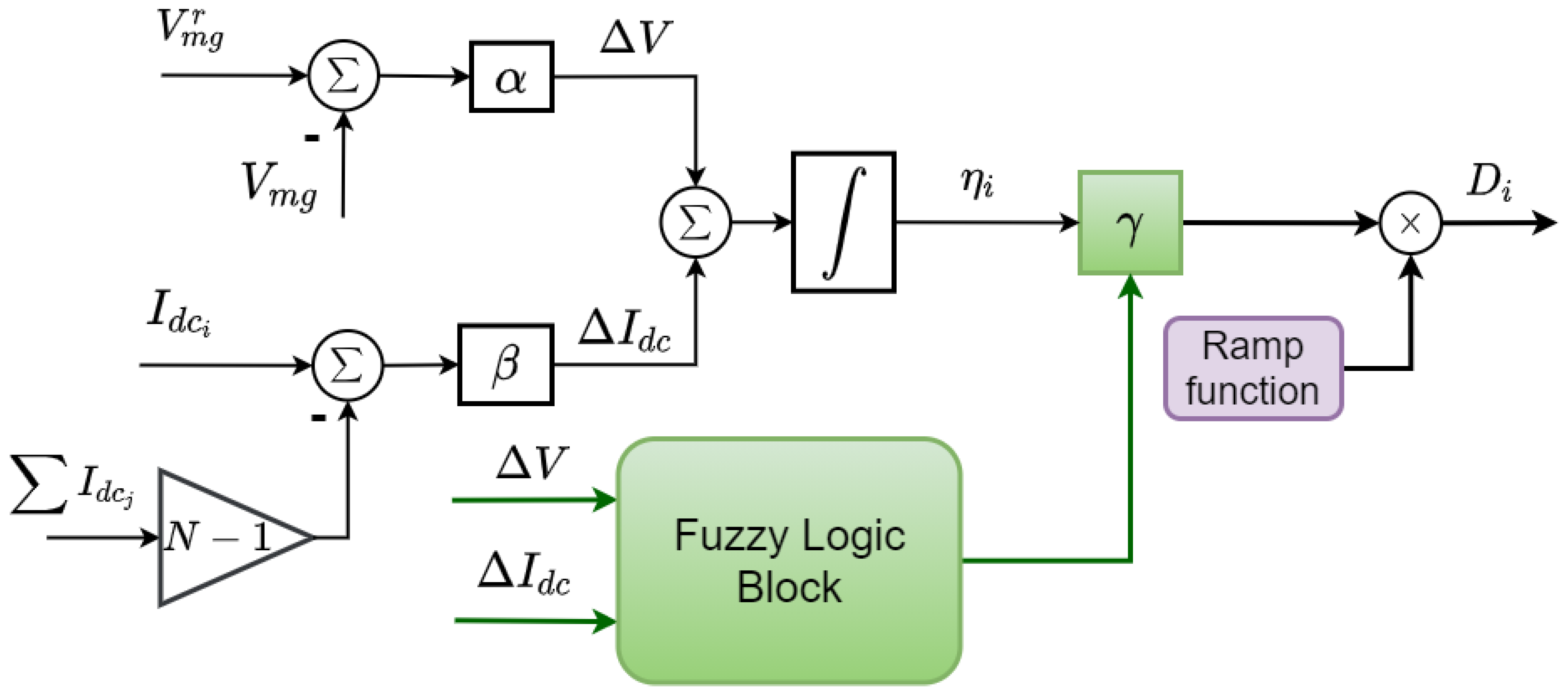
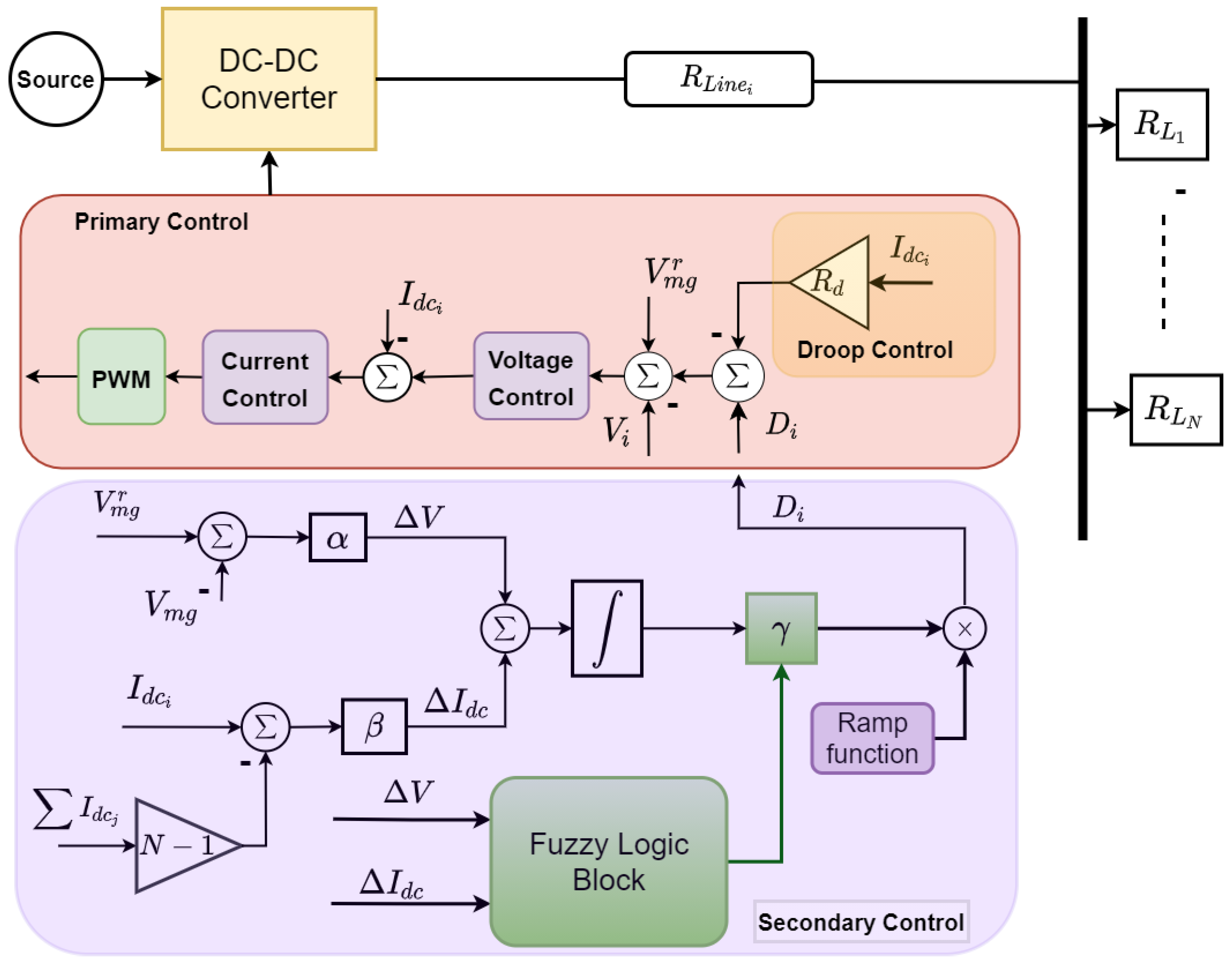
The overall control feature of the posited distributed fuzzy-based control for a DC setup is shown in Figure 3. The traditional droop technique is used by the primary control for current sharing among parallel converters. A variation in the output voltage of the converters is caused by the droop control. The control is implemented to make up for the voltage variation. The posited controller uses the fuzzy logic method to generate the control input/reference signal to the control to offset the voltage error and concurrently ascertain balanced current sharing among the converters. The voltage of the DC bus can also be affected by the line resistance and changes in load in the . In the proposed fuzzy-dependent controller, the fuzzy logic method inputs are the voltage variation () and current-sharing error (), while the fuzzy logic output is the factor of the controller. Therefore, the distributed controller for the ith converter can be expressed as
where is the fuzzy logic system. The fuzzy logic uses membership functions (MFs) over the universe of discourse to provide a nonlinear mapping between the input and output variables. In this work, five triangular MFs—positive big (PB), positive small (PS), negative small (NS), negative big (NB), and zero (Z)—are chosen as input parameters, and three triangular MFs—big (B), medium (M), and small (S)—are chosen as output parameters. The if-then rules for the inference engine are designed depending on the control goals and system behavior. Expressed in Table 1 are the rules for the fuzzy system. The defuzzification process is achieved using the center-of-gravity method [46]. To achieve the distributed control, each DS in the exchanges information with neighboring DSs using a sparse communication network. Although it is beyond the scope of this work, it is important to mention that the tertiary control layer also decides the current sharing property of the DSs in the depending on various operating states and the availability of the microsource.
4. Results and Discussion
This section evaluates the proposed fuzzy-based distributed control’s robustness. In the DC setup, four DSs and three constant power loads (i.e., DC loads—batteries and LED lights) are considered. Each DS has a DC/DC buck converter with the control loop. The control loop is developed for each DS to relate with other DSs via a communication network to realize distributed control. The system setup parameters are provided in Table 2. To test the robustness of the proposed controller, its capability in realizing the control goals is demonstrated; its potential to be plugged-and-played is examined; its behavior under communication time delay is assessed. The setup is built in the MATLAB/Simulink system, and all analyses/simulations are carried out in the real-time digital simulation machine known as Speedgoat. The Speedgoat simulator is a technology with modern ideas and features with a real-time network, using real-time testing developed for Simulink Real-Time toolboxes delivered by MathWorks. It finds applications in simulations requiring control algorithms, test systems with rapid control prototypes, and hardware-in-the-loop developed in the MATLAB/Simulink package.
4.1. Scenario A: Realization of Control Objectives
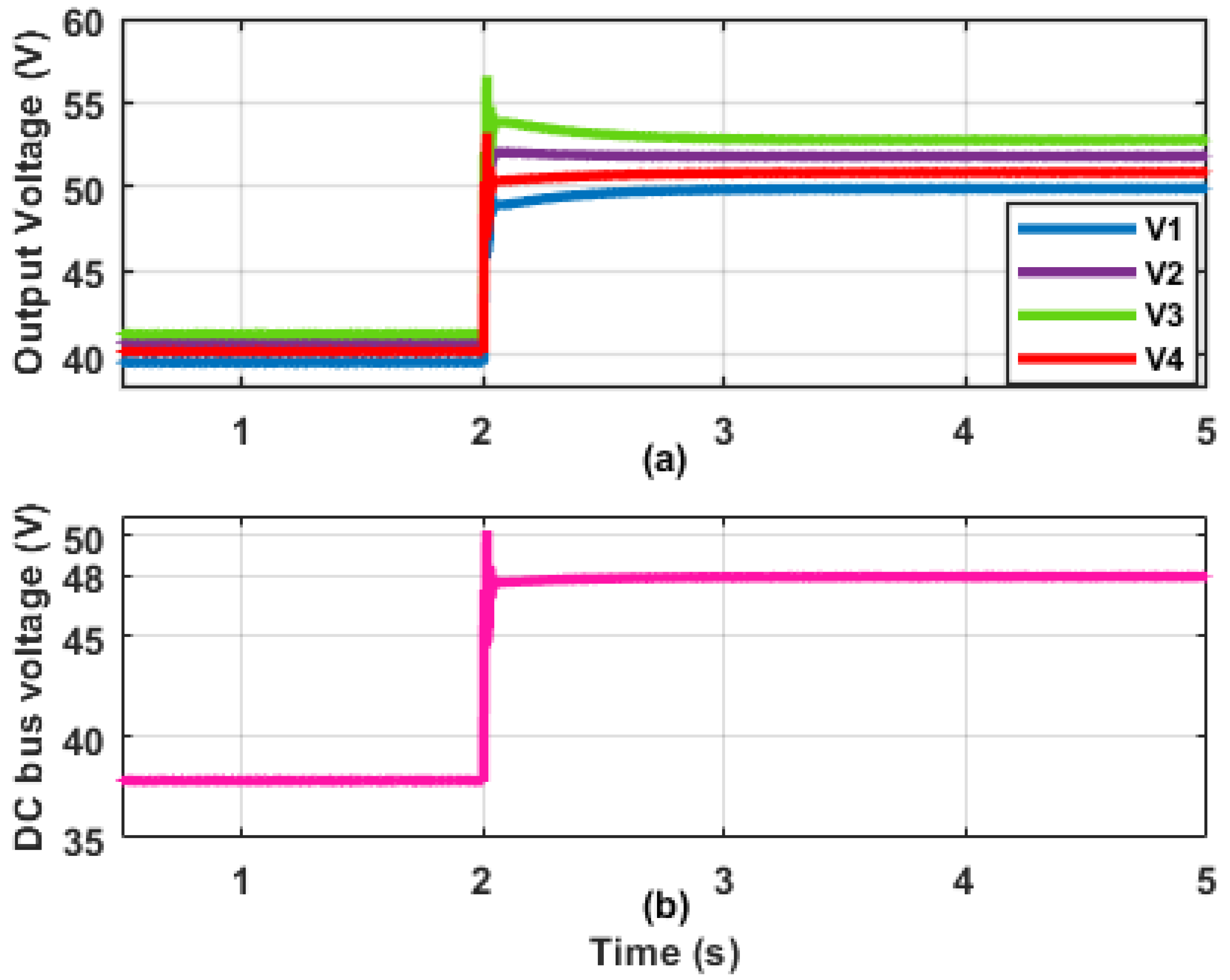
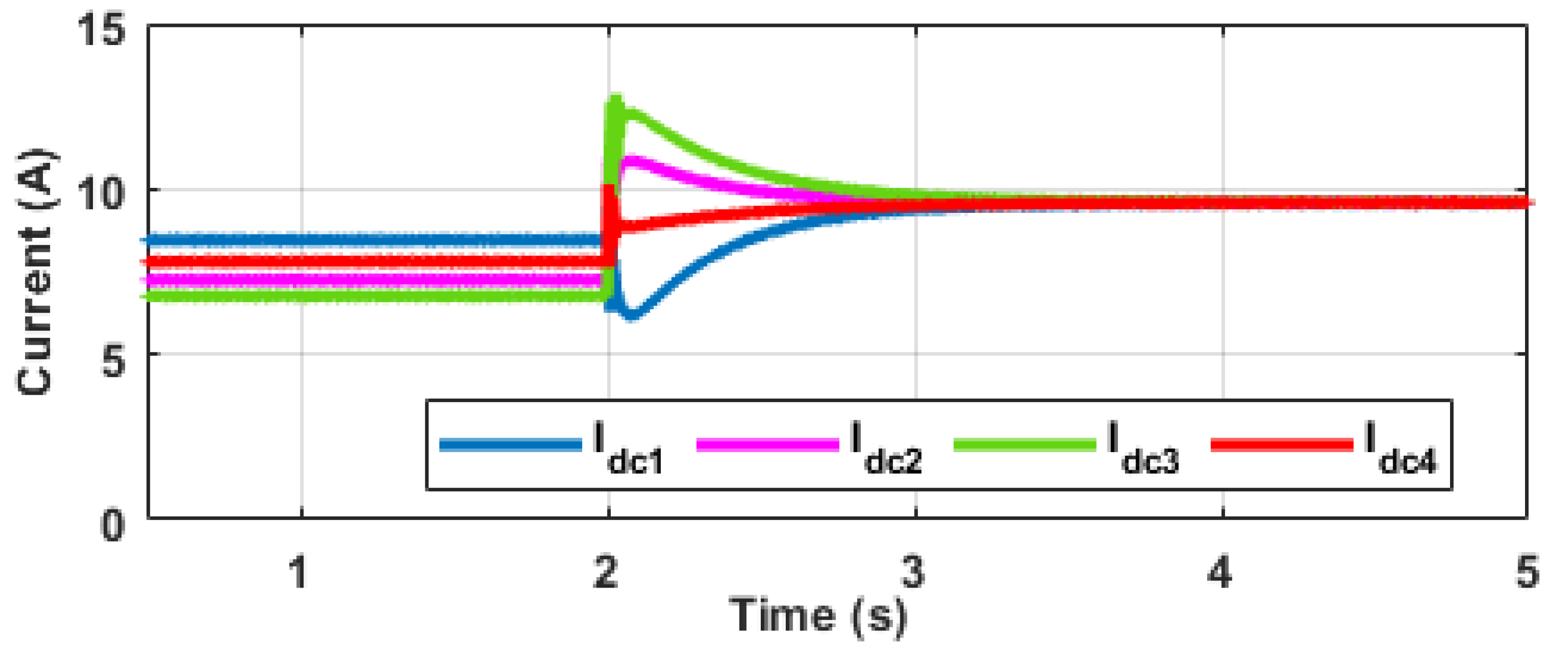
The efficacy of the posited controller to realize the control goals of balanced voltage regulation and current sharing is hereby examined. The results of the proposed distributed fuzzy-based control are comparatively evaluated with the traditional controller (S1), the supervisory controller (S2) proposed in [39], the distributed consensus controller (S3) proposed in [42], and the model predictive controller (S4) presented in [47]. The simulation is in two stages; in the first stage (0–2 s), only the /droop control in each DS is activated; in the second stage (2–5 s), the proposed distributed controller is enabled in each DS. Figure 4, Figure 5 and Figure 6 show the results of the simulation in this scenario. The plots in Figure 4a,b reveal the output voltage of each DS and the voltage of the DC bus, respectively. It can be observed in the first stage that the output voltages of the DSs are within 38–40 V, while the voltage of the DC bus is 38 V. This is a result of the variation initiated by the droop control as expressed in (2) and (3). When the controller is triggered at 2 s, the voltage of the DC bus rises and reaches the rated value s. Due to the non-negligible line resistance considered in this work, the output voltages of the DSs are observed to be higher than the DC bus voltage; this ensures that the DC bus voltage remains at 48V to satisfy (10). Similarly, the result for the current-sharing objective is shown in Figure 5. It is observed from the first stage that despite the same current-sharing ratio (), the output currents of the DSs are different. However, in the second stage, the current-sharing deviations are eliminated, and the output currents come together to a common value to satisfy (8) and (9).
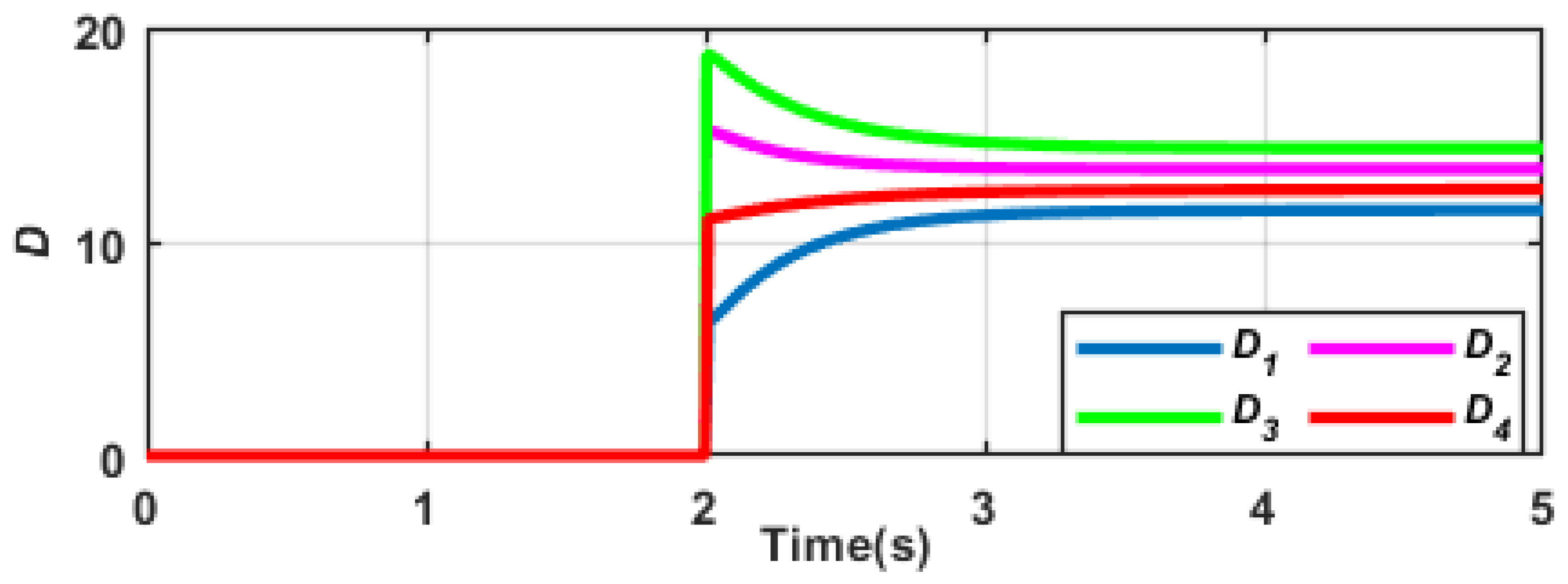
To elucidate the advantage of the proposed distributed controller, Table 3 shows the time taken for the distributed controllers S1 and S2 previously proposed in the literature to achieve the control objectives. The proposed fuzzy-based controller could be observed to provide the fastest convergence for voltage regulation and current-sharing goals amid the controllers. The output of the proposed distributed control that accomplishes the control objectives for each DS is shown in Figure 6.
4.2. Scenario B: Plug-and-Play Ability
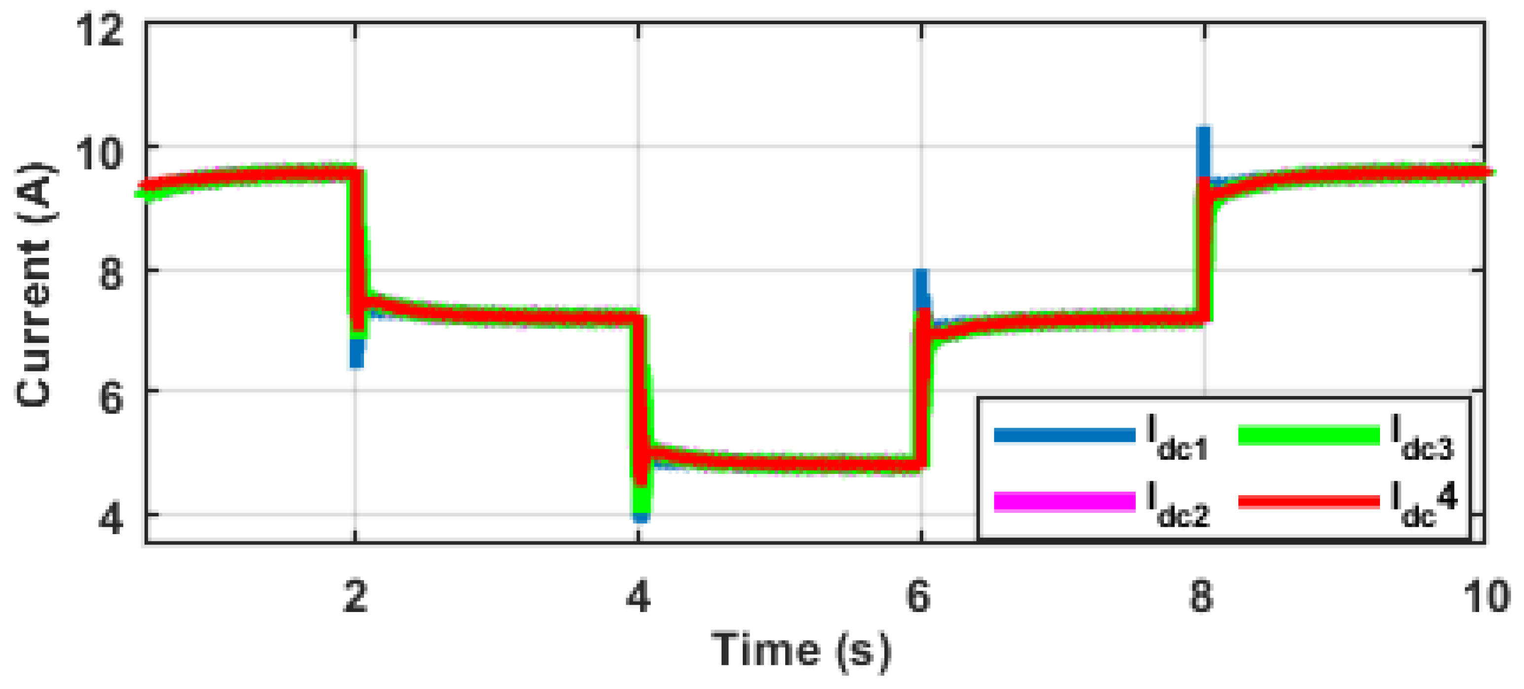
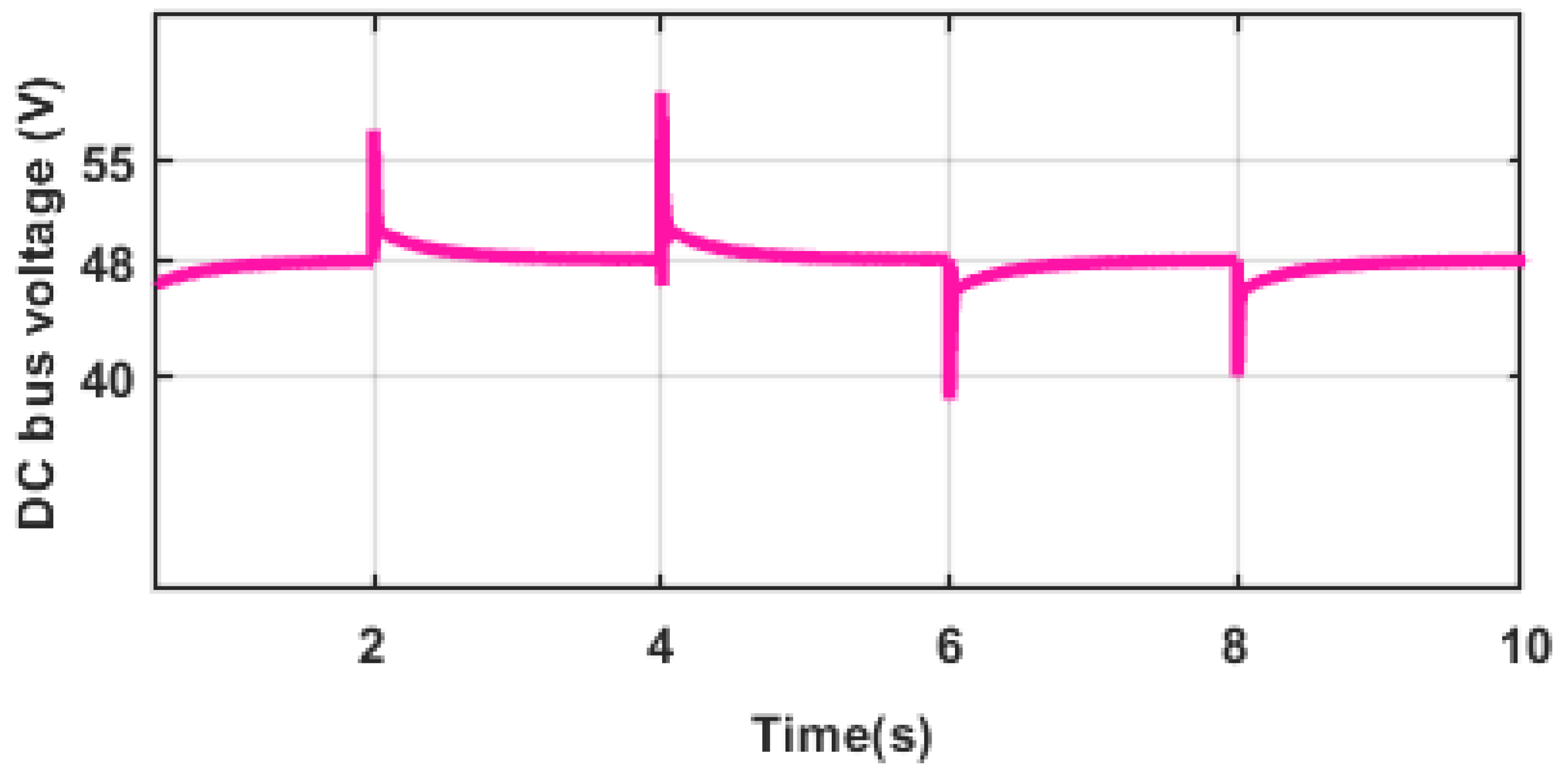
The strength of the proposed controller is hereby examined by considering the connection and disconnection of loads. Under this scenario, the distributed controller in each DS is expected to reach a new balanced current-sharing condition and sustain the voltage of the bus at the rated value when one or more loads are added to or removed from the system. To analyze this scenario, two loads ( and ) are disconnected at 2 s and 4 s, respectively, from the system and reconnected at 6 s and 8 s, respectively. Figure 7 and Figure 8 show the simulation results. Figure 7 shows a balanced current sharing of approximately 9.5 A amongst the DS before the disconnection of . At 2 s, there is a concurrent current drop by all DS to a new value of 7.2 A, with a further current drop to 5 A at 4 s when is disconnected. When the load is reconnected at 6 s and 8 s, the proposed controller ensures that each DS achieves equal current sharing. For the voltage restoration objective, Figure 8 shows that the voltage of the DC bus is sustained at the reference value of 48 V after the sudden transients inflicted by the connection and disconnection of the loads. The system was designed for a voltage deviation of between of the steady-state voltage with a settling time of approximately 500 ms postcontingency. Figure 8 shows a worst-case scenario where the voltage limits were violated during the switching of the loads; however, rapid action of the proposed controller offsets the deviation with a quick settling time to steady-state condition. These results reveal that the posited fuzzy-dependent distributed controller is capable of achieving equal voltage restoration and current-sharing goals under the plug-and-play property of the connected loads.
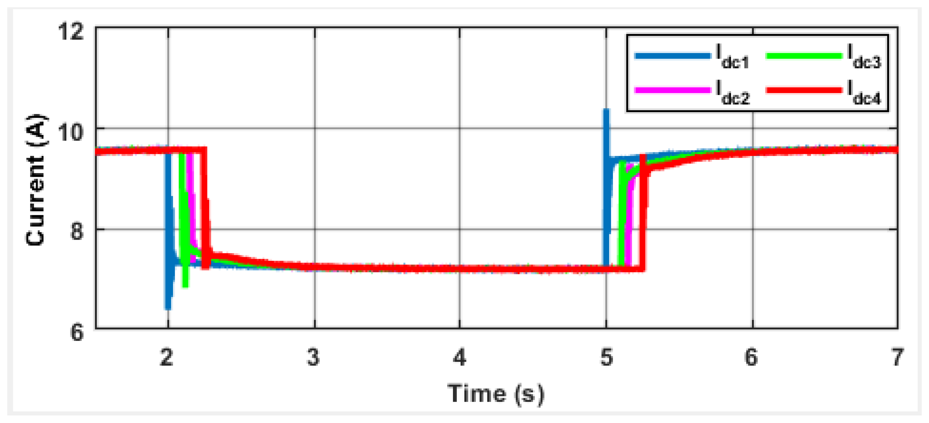
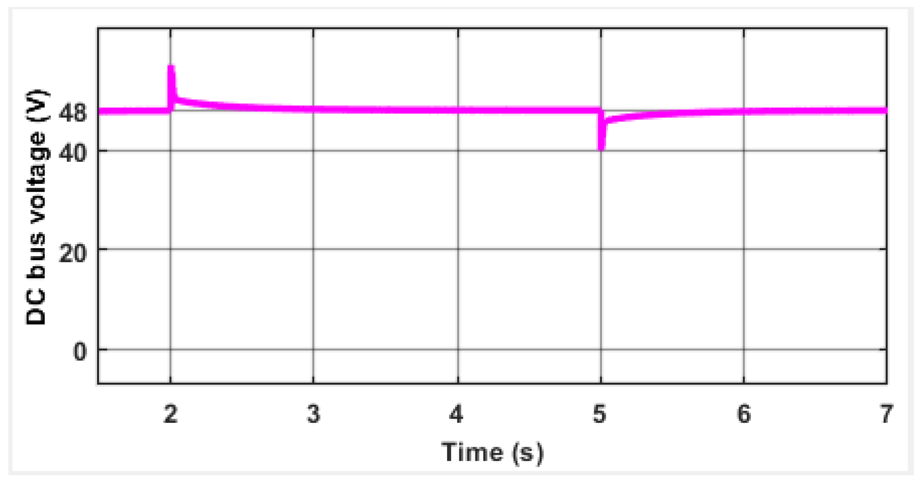
4.3. Scenario C: Robustness under Communication Time-Delay
As aforementioned, distributed controllers require communication links to interact with one another within the to achieve a consensus in the control goals. It is, therefore, important to study the effect of time delays in the communication networks on the effectiveness of the proposed distributed controller. In this scenario, we investigate the effect of time delay in the current-carrying communication link because current sharing is a consensus-based objective that demands communication. It is important to point out that the time delays considered in this scenario are intrinsic to communications channels and are not as large to mimic a time-delay attack scenario, which may significantly impact the system stability. The delays include 150 ms, 100 ms, and 250 ms in the links transporting the current signal from DS2, DS3, and DS4, respectively. To change the current-sharing property of the proposed controller and examine the effect of the time delays, is disconnected at 2 s and reconnected at 5 s. The results of the simulations are shown in Figure 9 and Figure 10. From the result in Figure 9, it is seen that the proposed distributed controller in each DS can reach consensus in the current-sharing objective within 1 s despite the associated time delays in the communication link of each DS. Since the voltage restoration goal is a global goal, it is observed from Figure 10 that the DC bus voltage is sustained at the reference value after each contingency. Analytical studies reveal that the large time delays in the communication links make the current signal highly oscillatory and may lead to instability in the system. This is because the current-sharing error is computed using the present output current of one DS and the delayed current from other DSs in the .
5. Conclusions
A fuzzy-dependent distributed control method for balanced current sharing and voltage regulation in AN off-grid DC is proposed in this research. The distributed generators are linked in parallel to a common DC bus to supply the connected loads. The fuzzy logic scheme uses the current-sharing error and voltage variations triggered by the droop control to generate an appropriate control coefficient to ascertain balanced voltage regulation and current sharing. The effect of line resistance on the converter’s output current is factored in while designing the proposed controller. The proposed control technique’s stability criteria are developed using the Lyapunov stability technique. The capability of the distributed controller’s effective performance in communication time delay and plugged-and-played mode compared to classical distributed controllers is demonstrated by the simulation results. In addition, extending the developed strategy to handle current-sharing and voltage regulation control problems in multiport converters in grid-connected DC should be investigated further in the future. Also, how to design the fuzzy-dependent distributed controller integrated with hybrid energy systems (HES) deserves further investigation.
Author Contributions
Conceptualization, A.K.O. and A.A.; Methodology, A.K.O. and A.A.; Software, A.K.O. and A.A.; Validation, G.S., P.N.B. and G.P.; Formal analysis, A.K.O. and A.A.; Investigation, P.N.B.; Resources, G.S., P.N.B. and G.P.; Data curation, A.K.O.; Writing—original draft, A.K.O. and A.O.A.; Supervision, G.S. and P.N.B.; Project administration, G.S.; Funding acquisition, G.P. All authors have read and agreed to the published version of the manuscript.
Funding
This research was funded by the University of Johannesburg Faculty—University Research Committee (Faculty–URC) funding, 2022–2023. The APC was partly funded by the Faculty of Engineering and Architecture, Kore University of Enna, 94100 Enna, Italy.
Institutional Review Board Statement
Not applicable.
Data Availability Statement
Not applicable.
Conflicts of Interest
The authors declare no conflict of interest.
Abbreviations
| Primary | |
| Secondary | |
| 3C | Communication, Computation, and Control |
| AC | Alternating Current |
| CPSs | Cyber-Physical Systems |
| DC | Direct Current |
| DSs | Distributed Sources |
| HES | Hybrid Energy Systems |
| HIL | Hardware-In-Loop |
| LFC | Load Frequency Controller |
| MIMO | Multiple-Input, Multiple-Output |
| MPPT | Maximum Power Point Tracking |
| SOC | State-of-charge |
| WPS | Wind Power Systems |
| Microgrids |
References
- Khalil, S.M.; Bahsi, H.; Ochieng’Dola, H.; Korõtko, T.; McLaughlin, K.; Kotkas, V. Threat Modeling of Cyber-Physical Systems—A Case Study of a Microgrid System. Comput. Secur. 2023, 124, 102950. [Google Scholar] [CrossRef]
- Aluko, A.O.; Carpanen, R.P.; Dorrell, D.G.; Ojo, E.E. Real-Time Cyber Attack Detection Scheme for Standalone Microgrids. IEEE Internet Things J. 2022, 9, 21481–21492. [Google Scholar] [CrossRef]
- Mthukuse, N.; Onaolapo, A.K.; Aluko, A.; Dorrell, D.G. Review of cyberattack implementation, detection, and mitigation methods in cyber-physical systems. Energies 2023, 16, 5206. [Google Scholar] [CrossRef]
- Guo, J.; Liu, W.; Syed, F.R.; Zhang, J. Reliability assessment of a cyber-physical microgrid system in island mode. CSEE J. Power Energy Syst. 2019, 5, 46–55. [Google Scholar] [CrossRef]
- Adefarati, T.; Bansal, R.C. Reliability and economic evaluation of a microgrid power system. Energy Procedia 2017, 142, 43–48. [Google Scholar] [CrossRef]
- Aluko, A.O.; Carpanen, R.P.; Dorrell, D.G.; Ojo, E.E. Real-Time Dynamic Disturbance Estimation of Stand-Alone Microgrids Based on Unknown Input Observer for Frequency Regulation. In Proceedings of the IEEE PES/IAS PowerAfrica, Nairobi, Kenya, 23–27 August 2021; pp. 1–5. [Google Scholar] [CrossRef]
- Shan, Y.; Hu, J.; Chan, K.W.; Islam, S. A Unified Model Predictive Voltage and Current Control for Microgrids with Distributed Fuzzy Cooperative Secondary Control. IEEE Trans. Ind. Inform. 2021, 17, 8024–8034. [Google Scholar] [CrossRef]
- Onaolapo, A.K.; Pillay Carpanen, R.; Dorrell, D.G.; Ojo, E.E. Reliability evaluation and financial viability of an electricity power micro-grid system with the incorporation of renewable energy sources and energy storage: A case study of KwaZulu-Natal, South Africa. IEEE Access 2021, 9, 159908–159924. [Google Scholar] [CrossRef]
- Adefarati, T.; Sharma, G.; Onaolapo, A.K.; Njepu, A.; Akindeji, K.T.; Oladejo, S.O.; Obikoya, G.D.; Adeyanju, I. Optimal design and techno-economic analysis of a grid-connected photovoltaic and battery hybrid energy system. Int. J. Eng. Res. Afr. (JERA) 2022, 60, 125–154. [Google Scholar] [CrossRef]
- Adefarati, T.; Obikoya, G.D.; Onaolapo, A.K.; Njepu, A. Design and analysis of a photovoltaic-battery-methanol-diesel power system. Int. Trans. Electr. Energy Syst. (ITEES) 2021, 31, e12800. [Google Scholar] [CrossRef]
- Adefarati, T.; Obikoya, G.D.; Sharma, G.; Onaolapo, A.K.; Akindeji, K.T. Design and Feasibility Analysis of Grid-Connected Hybrid Renewable Energy System: Perspective of Commercial Buildings. Energy Syst. 2023, 2023, 1–60. [Google Scholar] [CrossRef]
- Onaolapo, A.K.; Ojo, E.E. Effects of Upside Risk on Microgrids’ Reliability Considering the COVID-19 Pandemic. In Proceedings of the Southern African Universities Power Engineering Conference (SAUPEC), Johannesburg, South Africa, 24–26 January 2023; Volume 2023, pp. 1–6. [Google Scholar]
- Lin, P.; Zhang, C.; Zhang, X.; Iu, H.H.C.; Yang, Y.; Blaabjerg, F. Finite-time large signal stabilization for high power DC microgrids with exact offsetting of destabilizing effects. IEEE Trans. Ind. Electron. 2020, 68, 4014–4026. [Google Scholar] [CrossRef]
- Meng, L.; Shafiee, Q.; Trecate, G.F.; Karimi, H.; Fulwani, D.; Lu, X.; Guerrero, J.M. Review on control of DC microgrids and multiple microgrid clusters. IEEE J. Emerg. Sel. Top. Power Electron. 2017, 5, 928–948. [Google Scholar]
- Abhishek, A.; Ranjan, A.; Devassy, S.; Verma, B.K.; Ram, S.K.; Dhakar, A.K. Review of hierarchical control strategies for DC microgrid. IET Renew. Power Gener. 2020, 14, 1631–1640. [Google Scholar] [CrossRef]
- Bansal, R.C.; Bhatti, T.S. Small Signal Analysis of Isolated Hybrid Power Systems: Reactive Power and Frequency Control Analysis; Alpha Science International: Oxford, UK, 2008; pp. 1–240. [Google Scholar]
- Shrivastava, S.; Subudhi, B. Comprehensive review on hierarchical control of cyber-physical microgrid system. IET Gener. Transm. Distrib. 2020, 14, 6397–6416. [Google Scholar] [CrossRef]
- Liu, X.; Bansal, R.C. Integrating Multi-objective optimization with computational fluid dynamics to optimize boiler combustion process of a coal-fired power plant. Appl. Energy 2014, 114, 658–669. [Google Scholar] [CrossRef]
- Kumar, D.; Mathur, H.D.; Bhanot, S.; Bansal, R.C. Modeling and frequency control of community micro-grid under stochastic wind and solar sources. Int. J. Eng. Sci. Technol. (JESTECH) 2020, 23, 1084–1091. [Google Scholar] [CrossRef]
- Kumar, D.; Mathur, H.; Bhanot, S.; Bansal, R.C. Forecasting of solar and wind power using LSTM RNN for load frequency control in isolated microgrid. Int. J. Model. Simul. 2021, 41, 311–323. [Google Scholar] [CrossRef]
- Xing, L.; Guo, F.; Liu, X.; Wen, C.; Mishra, Y.; Tian, Y.C. Voltage Restoration and Adjustable Current Sharing for DC Microgrid with Time Delay via Distributed Secondary Control. IEEE Trans. Sustain. Energy 2020, 12, 1068–1077. [Google Scholar] [CrossRef]
- Anand, S.; Fernandes, B. Modified droop controller for paralleling of DC–DC converters in standalone DC system. IET Power Electron. 2012, 5, 782–789. [Google Scholar] [CrossRef]
- Wu, D.; Tang, F.; Dragicevic, T.; Guerrero, J.M.; Vasquez, J.C. Coordinated control based on bus-signaling and virtual inertia for islanded DC microgrids. IEEE Trans. Smart Grid 2015, 6, 2627–2638. [Google Scholar] [CrossRef] [Green Version]
- Lu, X.; Guerrero, J.M.; Sun, K.; Vasquez, J.C. An improved droop control method for DC microgrids based on low bandwidth communication with DC bus voltage restoration and enhanced current sharing accuracy. IEEE Trans. Power Electron. 2013, 29, 1800–1812. [Google Scholar] [CrossRef] [Green Version]
- Lin, P.; Zhang, C.; Wang, P.; Xiao, J. A decentralized composite controller for unified voltage control with global system large-signal stability in DC microgrids. IEEE Trans. Smart Grid 2018, 10, 5075–5091. [Google Scholar] [CrossRef]
- Saafan, A.A.; Khadkikar, V.; El Moursi, M.S.; Zeineldin, H.H. A New Multiport DC-DC Converter for DC Microgrid Applications. IEEE Trans. Ind. Appl. 2023, 59, 601–611. [Google Scholar] [CrossRef]
- Wang, B.; Wang, Y.; Xu, Y.; Zhang, X.; Gooi, H.B.; Ukil, A.; Tan, X. Consensus-based Control of Hybrid Energy Storage System with a Cascaded Multiport Converter in DC Microgrids. IEEE Trans. Sustain. Energy 2019, 11, 2356–2366. [Google Scholar] [CrossRef]
- Yan, S.; Gu, Z.; Park, J.H.; Xie, X.; Dou, C. Probability-Density-Dependent Load Frequency Control of Power Systems with Random Delays and Cyber-Attacks via Circuital Implementation. IEEE Trans. Smart Grids 2022, 13, 4837–4847. [Google Scholar] [CrossRef]
- Yan, S.; Gu, Z.; Park, J.H.; Xie, X. Sampled Memory-Event-Triggered Fuzzy Load Frequency Control for Wind Power Systems Subject to Outliers and Transmission Delays. IEEE Trans. Cybern. 2023, 50, 4043–4053. [Google Scholar] [CrossRef] [PubMed]
- de Oliveira, R.C.; Tofoli, F.L.; de Morais, A.S. Novel Isolated Multiple-Input, Multiple-Output Multidirectional Converter for Modern Low-Voltage DC Power Distribution Architectures. Sustainability 2023, 15, 4582. [Google Scholar] [CrossRef]
- Guerrero, J.M.; Vasquez, J.C.; Matas, J.; De Vicuña, L.G.; Castilla, M. Hierarchical control of droop-controlled AC and DC microgrids—A general approach toward standardization. IEEE Trans. Ind. Electron. 2010, 58, 158–172. [Google Scholar] [CrossRef]
- Bansal, R.C. Automatic Reactive Power Control of Autonomous Hybrid Power Systems. Ph.D. Thesis, Indian Institutes of Technology, Delhi, India, 2003. [Google Scholar]
- Mbungu, N.T.; Ismail, A.A.; AlShabi, M.A.; Bansal, R.C.; ElNady, A.M.; Hamid, A.K. Control and estimation techniques applied to smart microgrids: A review. Renew. Sustain. Energy Rev. 2023, 179, 1–21. [Google Scholar] [CrossRef]
- Trip, S.; Cucuzzella, M.; Cheng, X.; Scherpen, J. Distributed averaging control for voltage regulation and current sharing in DC microgrids. IEEE Control Syst. Lett. 2018, 3, 174–179. [Google Scholar] [CrossRef] [Green Version]
- Aluko, A.; Swanson, A.; Jarvis, L.; Dorrell, D. Modeling and Stability Analysis of Distributed Secondary Control Scheme for Stand-Alone DC Microgrid Applications. Energies 2022, 15, 5411. [Google Scholar] [CrossRef]
- Aluko, A.; Buraimoh, E.; Oni, O.E.; Davidson, I.E. Advanced Distributed Cooperative Secondary Control of Islanded DC Microgrids. Energies 2022, 15, 3988. [Google Scholar] [CrossRef]
- Krishna Metihalli, B.; Narayana Sabhahit, J. Disturbance Observer Based Distributed Consensus Control Strategy of Multi-Agent System with External Disturbance in a Standalone DC Microgrid. Asian J. Control 2021, 23, 920–936. [Google Scholar] [CrossRef]
- Liu, X.K.; He, H.; Wang, Y.W.; Xu, Q.; Guo, F. Distributed hybrid secondary control for a DC microgrid via discrete-time interaction. IEEE Trans. Energy Convers. 2018, 33, 1865–1875. [Google Scholar] [CrossRef]
- Liu, X.K.; Wang, Y.W.; Lin, P.; Wang, P. Distributed supervisory secondary control for a DC microgrid. IEEE Trans. Energy Convers. 2020, 35, 1736–1746. [Google Scholar] [CrossRef]
- Sahoo, S.; Mishra, S. A distributed finite-time secondary average voltage regulation and current sharing controller for DC microgrids. IEEE Trans. Smart Grid 2017, 10, 282–292. [Google Scholar] [CrossRef]
- Guo, F.; Xu, Q.; Wen, C.; Wang, L.; Wang, P. Distributed secondary control for power allocation and voltage restoration in islanded DC microgrids. IEEE Trans. Sustain. Energy 2018, 9, 1857–1869. [Google Scholar] [CrossRef]
- Dong, M.; Li, L.; Nie, Y.; Song, D.; Yang, J. Stability analysis of a novel distributed secondary control considering communication delay in DC microgrids. IEEE Trans. Smart Grid 2019, 10, 6690–6700. [Google Scholar] [CrossRef]
- Bhargavi, K.; Jayalakshmi, N. Leader–Follower-Based Distributed Secondary Voltage Control for a Stand-alone PV and Wind-Integrated DC Microgrid System with EVs. J. Control Autom. Electr. Syst. 2020, 31, 233–246. [Google Scholar] [CrossRef]
- Deng, C.; Wang, Y.; Wen, C.; Xu, Y.; Lin, P. Distributed resilient control for energy storage systems in cyber–physical microgrids. IEEE Trans. Ind. Inform. 2020, 17, 1331–1341. [Google Scholar] [CrossRef]
- Aluko, A.O.; Carpanen, R.P.; Dorrell, D.G.; Ojo, E.E. Robust State Estimation Method for Adaptive Load Frequency Control of Interconnected Power System in a Restructured Environment. IEEE Syst. J. 2021, 15, 5046–5056. [Google Scholar] [CrossRef]
- Aluko, A.O.; Musumpuka, R.; Dorrell, D.G. Cyberattack-Resilient Secondary Frequency Control Scheme for Stand-Alone Microgrids. IEEE Trans. Ind. Electron. 2023, 70, 1622–1634. [Google Scholar] [CrossRef]
- Chandrasekar, A.; Sengupta, S.; Hingane, S.; Gururaja, C.; Pandit, S. Comparative Analysis of Model Predictive Control (MPC) and Conventional Control in Supervisory Controller of a Retrofit HEV; SAE Technical Paper; SAE International: Warrendale, PA, USA, 2017; pp. 1–10. [Google Scholar] [CrossRef]
Figure 1.
Block diagram of DC with and control.

Figure 2.
The posited fuzzy-dependent distributed control method.

Figure 3.
Comprehensive block diagram of proposed distributed control scheme for a DC .

Figure 4.
(a) Output voltage of each DS (b) DC bus voltage of in Scenario A.

Figure 5.
Output current of each DS in the for Scenario A.

Figure 6.
Output of the posited distributed controller.

Figure 7.
Output current of each DS in the in Scenario B.

Figure 8.
DC bus voltage in Scenario B.

Figure 9.
Output current of each DS in the in Scenario C.

Figure 10.
DC bus voltage in Scenario C.


Table 1.
Table of fuzzy rules.
| NB | NS | Z | PS | PB | ||
| NB | B | B | M | M | M | |
| NS | B | B | S | M | M | |
| Z | B | S | S | S | B | |
| PS | M | M | S | B | B | |
| PB | M | M | M | B | B | |
Table 2.
System parameters.
| Description | Unit | Value |
|---|---|---|
| Rated Bus Voltage | 48 V | |
| Source Voltage | 100 V | |
| Sampling Frequency | 10 kHz | |
| Filter Inductance | 1 mH | |
| Filter Capacitance | 235 | |
| Line Resistance | 0.2 , 0.4 , 0.5 , 0.3 | |
| Load | 5 , 2.5 , 4 | |
| Control loop | ||
| Current Control | 0.05 | |
| 148 | ||
| Voltage Control | 0.248 | |
| 36 | ||
| Droop Resistance | 1 | |
| Control loop | ||
| Voltage Error Coefficient | 1.25 | |
| Current Error Coefficient | 7.5 | |
Table 3.
Comparison of the proposed controller with other controllers for Scenario A.
| Control Objective | S1 | S2 | S3 | S4 | Proposed |
|---|---|---|---|---|---|
| Voltage Regulation | 2 s | 1.72 s | 3 s | 1.3 s | ≤0.2 s |
| Current Sharing | 2.5 s | 2 s | 3.4 s | 1.5 s | 1 s |
| Implementation Complexity | simple | simple | simple | complex | complex |
| Robustness | low | moderate | moderate | high | very high |
Disclaimer/Publisher’s Note: The statements, opinions and data contained in all publications are solely those of the individual author(s) and contributor(s) and not of MDPI and/or the editor(s). MDPI and/or the editor(s) disclaim responsibility for any injury to people or property resulting from any ideas, methods, instructions or products referred to in the content. |
© 2023 by the authors. Licensee MDPI, Basel, Switzerland. This article is an open access article distributed under the terms and conditions of the Creative Commons Attribution (CC BY) license (https://creativecommons.org/licenses/by/4.0/).
Share and Cite
MDPI and ACS Style
Onaolapo, A.K.; Sharma, G.; Bokoro, P.N.; Aluko, A.; Pau, G. A Distributed Control Scheme for Cyber-Physical DC Microgrid Systems. Energies 2023, 16, 5611. https://doi.org/10.3390/en16155611
AMA Style
Onaolapo AK, Sharma G, Bokoro PN, Aluko A, Pau G. A Distributed Control Scheme for Cyber-Physical DC Microgrid Systems. Energies. 2023; 16(15):5611. https://doi.org/10.3390/en16155611
Chicago/Turabian StyleOnaolapo, Adeniyi K., Gulshan Sharma, Pitshou N. Bokoro, Anuoluwapo Aluko, and Giovanni Pau. 2023. "A Distributed Control Scheme for Cyber-Physical DC Microgrid Systems" Energies 16, no. 15: 5611. https://doi.org/10.3390/en16155611
Note that from the first issue of 2016, this journal uses article numbers instead of page numbers. See further details here.