Review

State-of-the-Art Grid Stability Improvement Techniques for Electric Vehicle Fast-Charging Stations for Future Outlooks

by
Kabir Momoh
1,
Shamsul Aizam Zulkifli
1,*,
Petr Korba
2,*,
Felix Rafael Segundo Sevilla
2,
Arif Nur Afandi
3 and
Alfredo Velazquez-Ibañez
2
1
Faculty of Electrical and Electronic Engineering FKEE, Universiti Tun Hussein Onn Malaysia, Batu Pahat 86400, Malaysia
2
School of Engineering, Zurich University of Applied Sciences, Technikumstrasse 9, 8401 Winterthur, Switzerland
3
Faculty of Engineering, Universitas Negeri Malang, JL. Semarang 5 Malang, Malang 65145, Indonesia
*
Authors to whom correspondence should be addressed.
Energies 2023, 16(9), 3956; https://doi.org/10.3390/en16093956
Submission received: 18 March 2023 / Revised: 20 April 2023 / Accepted: 2 May 2023 / Published: 8 May 2023

Abstract

:
The growing trend for electric vehicles (EVs) and fast-charging stations (FCSs) will cause the overloading of grids due to the high current injection from FCSs’ converters. The insensitive nature of the state of charge (SOC) of EV batteries during FCS operation often results in grid instability problems, such as voltage and frequency deviation at the point of common coupling (PCC). Therefore, many researchers have focused on two-stage converter control (TSCC) and single-stage converter (SSC) control for FCS stability enhancement, and suggested that SSC architectures are superior in performance, unlike the TSCC methods. However, only a few research works have focused on SSC techniques, despite the techniques’ ability to provide inertia and damping support through the virtual synchronous machine (VSM) strategy due to power decoupling and dynamic response problems. TSCC methods deploy current or voltage control for controlling EVs’ SOC battery charging through proportional-integral (PI), proportional-resonant (PR), deadbeat or proportional-integral-derivative (PID) controllers, but these are relegated by high current harmonics, frequency fluctuation and switching losses due to transient switching. This paper reviewed the linkage between the latest research contributions, issues associated with TSCC and SSC techniques, and the performance evaluation of the techniques, and subsequently identified the research gaps and proposed SSC control with SOC consideration for further research studies.

1. Introduction

The effects of global warming and abrupt climate change have been the primary concerns of environmental experts when combustion engines are being used [1,2]. The majority of studies have focused on the benefits of avoiding the further use of internal combustion engines, and now the trend of vehicle design is switching to electric vehicles (Evs) in order to reduce carbon emissions, safeguard against climate change and reduce global warming [3]. The transportation sector is the main source of contributions to recent worries about pollution and rising fuel consumption [4]. The use of Evs has been heavily encouraged over the past ten years, as suggested in [5]. Consequently, Evs’ growing popularity in the market has encouraged the development of other varieties of Evs, such as battery electric vehicles (BEVs) [6], hybrid vehicles (HVs) [7], fuel cell electric vehicles (FCEVs), and extended-range electric vehicles (ER-Evs) [8] for future exploration. Navigant Research has forecast a robust trend for global yearly EV adoption, as shown in Figure 1. It has identified a consistent increase in global EV integrations. In addition, the report in [9] projected that over 26.8 million BEVs will be sold globally between 2021 and 2030 [10]. However, this growing deployment of Evs will create a continuous rise in the charging load demand in electric grid networks [5]. This future deployment of Evs has positioned grid stability for EV fast-charging stations (FCSs) as the new focus for discussion [9,10] and research.
Therefore, in order to fulfill the demand for the considerable operation of Evs [10], EV FCS infrastructure to replace gas stations is urgently needed, especially in areas where long-distance trips are frequent or a common norm [10]. However, developing and implementing infrastructure such as FCS requires taking into account various technical standards and grid implications when Evs are connected to the grid for charging or discharging mode [10,11]. Furthermore, the connection of Evs to the grid will cause a sudden change in the characteristics of the power supply mode if not properly controlled or regulated [12]. The irregular changes brought about by EV batteries and the charging condition of the FCS will have a major effect on grid voltage and frequency at the point of common coupling (PCC) [13].
Moreover, the report in [12] showed that high reluctance power is often drawn from the grid during the fast-charging operation. Hence, EV penetration could possibly overstress the electric grid system when more loads are connected [12,14]. To solve these problems, the authors in [14] reported the use of the frequency and voltage regulation strategy as the major requirement for minimizing the upshoot in grid voltage due to the peak demand at the PCC, caused by high current harmonics emission by the FCSs [15]. The EV battery connection to the grid through an FCS is shown in Figure 2, where an AC-to-DC converter transforms the supplied AC input into a DC output, while a DC-to-DC converter ensures the transfer of power between the DC link and the EV battery to maintain the state of charge (SOC) [16]. This FCS possesses the capacity to provide 80% charge on the EV battery within a few minutes, with those rated 50 kW to above 350 kW [17] giving the best charging time and performance.
The FCSs are divided into three categories [18,19]. The first is level-one chargers, which have the capacity to offer between 50 Vdc and 500 Vdc with a maximum charging current of 125 A [19]. Level-two chargers are characterized by 410 Vdc with up to 300 A charging current [19,20]. Level-three chargers can accommodate over 800 Vdc with a corresponding charging current of 370 A, as shown in Figure 3 [20]. Recently, the authors in [20,21] reported an improvement in the rectification stage of the FCS by using the Swiss rectifier and the Vienna rectifier, respectively. These two approaches showed the reduction in harmonics in the line current (6.60%) when applied to a single-stage converter-based FCS. However, the drawbacks, as reported in [21], are the severely restricted reactive power generation and phase displacement angle between current and voltage waveforms. These drawbacks prevent the rectifier from functioning at the unity power factor, as observed by [22].
Consequently, apart from the transportation system network, this transition will have a direct impact on power grid supply stability at the PCC [19,22]. Thus, FCSs should be considered in the context of power grid stability. Grid stability is attained when the system responds to any transient change in frequency, current or voltage disturbances within the margin of the allowable standard operation of ±5% from the rated value [19]. On the other hand, the FCS control strategy often deploys controllers such as the proportional-integral (PI) converter [19,23] to ensure that the battery’s charging current is maintained at the rated value [22,23]. When this is achieved, the battery’s voltage is permitted to rise over the rated value [23]. Additionally, the inner-loop current control’s function is to control direct and quadrature grid currents (Id, Iq) to guarantee a ripple-free charging current, which enables active power and reactive power to be controlled [21,22,23]. In addition, the DC-link voltage is controlled by the outer voltage loop, which creates the reference current for the inner-loop current [24].
Most traditional controllers control converter switching by generating a control signal from the difference between the actual value and the target value [25]. This difference is expected to be zero or as small as possible to aid the efficiency of the EV battery charging process [24,25]. The output voltage is regulated by the current feedback loop in the FCS control loop in such a way that it responds to any variations or changes in the load profile of the FCS at the PCC [24]. Furthermore, the modulation aspect of the FCS achieves power delivery by generating a sequence of increasing or decreasing pulse widths [25]. As is known, there are various types of pulse-width modulation (PWM), such as phase displacement control (PDC) and space vector pulse-width modulation (SVPWM) [8,15]. These strategies offer the elimination of circuitry complexity issues and adaptability to voltage spikes and electromagnetic noise [26].
The authors in [27] demonstrated the possibility of faster charging speeds and times for higher-rated FCS of above 50 kW. However, when multiple FCSs with high power ratings are connected to the grid, attaining regulated frequency and voltage quality at the PCC will become difficult, as mentioned in [14,27]. This is because the load profile of the FCS will cause harmonics to line currents, as well as phase imbalances [28], and will change the line impedance with instantaneous applied voltage [22,28]. Therefore, when a higher-rated FCS is connected to the grid network for longer, the grid will start to see this FCS as a nonlinear source that absorbs power, which can jeopardize the stability and interrupt the efficiency of the entire network [29]. Figure 4 shows frequency fluctuation as a result of an increasing number of EV batteries in the FCS. Frequency fluctuation happens at the PCC because grid frequency deviates from its rated value due to the increased power exchange between the various EV batteries and the charging station, which also results in corresponding voltage sags at the PCC, as shown in Figure 5 [30]. Voltage sags occur when multiple Evs are applied at the FCS due to the EV load variation, causing a voltage reduction of 10% or more from its nominal value, which lasts between 0.5 cycles to one minute [31].
For a rectifier converter, any increase in the FCS load to the grid will cause a significant frequency disturbance to the power grid [30,31]. Therefore, this will require a higher initial grid stability reinforcement to ensure that the frequency setpoint is maintained. This is needed in order to avoid FCS power balancing requirement failure, harmonic disturbance, and grid instability [32]. The various options for minimizing the impact of grid instability require a critical investigation of existing grid stability strategies, as presented in this paper.
Several grid stability improvement techniques were proposed in [25,26,27,28,29,30,31,32,33]. These could be considered as either a two-stage converter control (TSCC) or single-stage converter (SSC) control, as shown in Figure 6 [33]. SSC control techniques provide more accuracy in grid stability improvement via the provision of inertial support through virtual synchronous machine (VSM) control of the rectifier converter. This approach enables the PI controller to be used for direct power control or a voltage control strategy [33,34]. Moreover, it also reduces the instantaneous errors within a specified hysteresis band for direct power control [33]. The voltage control strategy, as observed in [25], helps to regulate voltage with a wideband disturbance rejection capacity at the reference values of the converter’s input voltage at the rectification stage. However, the drawback, as reported in [34], is that this strategy is sensitive to grid voltage and frequency fluctuations at the PCC as the number of FCS loads increases.
TSCC techniques consist of two stages, and the first stage comprises the rectifier converter, which is the closest converter connected to the grid at the PCC. Grid stability is achieved by using current control at the rectification stage through traditional controllers, such as the proportional-resonant (PR), proportional-integral-derivative (PID) and deadbeat (DB) controllers, as classified in Figure 7. These controllers are utilized to allow precise current tracking to minimize the transient time and protect from overcurrent [35].
At the DC-DC converter stage, the transfer of power between the DC link and the EV battery is achieved for TSCC. Normally, this converter uses a voltage controller to regulate and generate an output DC voltage, which acts as a reference input to the voltage controller [25]. TSCC techniques are less effective, as reported in the literature [25,35]. This is because of the tendency for a reduced dynamic response towards the stability limit [36]. Additionally, a higher number of converter stages increases switching and power losses, which result in a more complex control architecture [37]. Examples of TSCC techniques include partial power control (PPC), mode-based control (MBC) and filter-based control (FBC). On the other hand, an example of SSC control is alternating-current-based control (ACBC) [8]. Before going deep into the discussion on the leading grid stability techniques and the causes of instabilities in the FCS control loop, it is pertinent to describe the structuring of this paper.
The various sections of this paper are outlined as follows: a concise discussion on two-stage converter control (TSCC) techniques for grid stability improvement is presented in Section 2, single-stage control (SSC) techniques for grid stability improvement are presented in Section 3, issues with TSCC techniques for rectifier control for stability are presented in Section 4, issues with SSC control techniques for rectifier control for stability are presented in Section 5, a concept of a virtual-synchronous-motor-based state-of-charge feedback control is presented in Section 6, future studies and development are discussed in Section 7, and the conclusion is presented in Section 8.

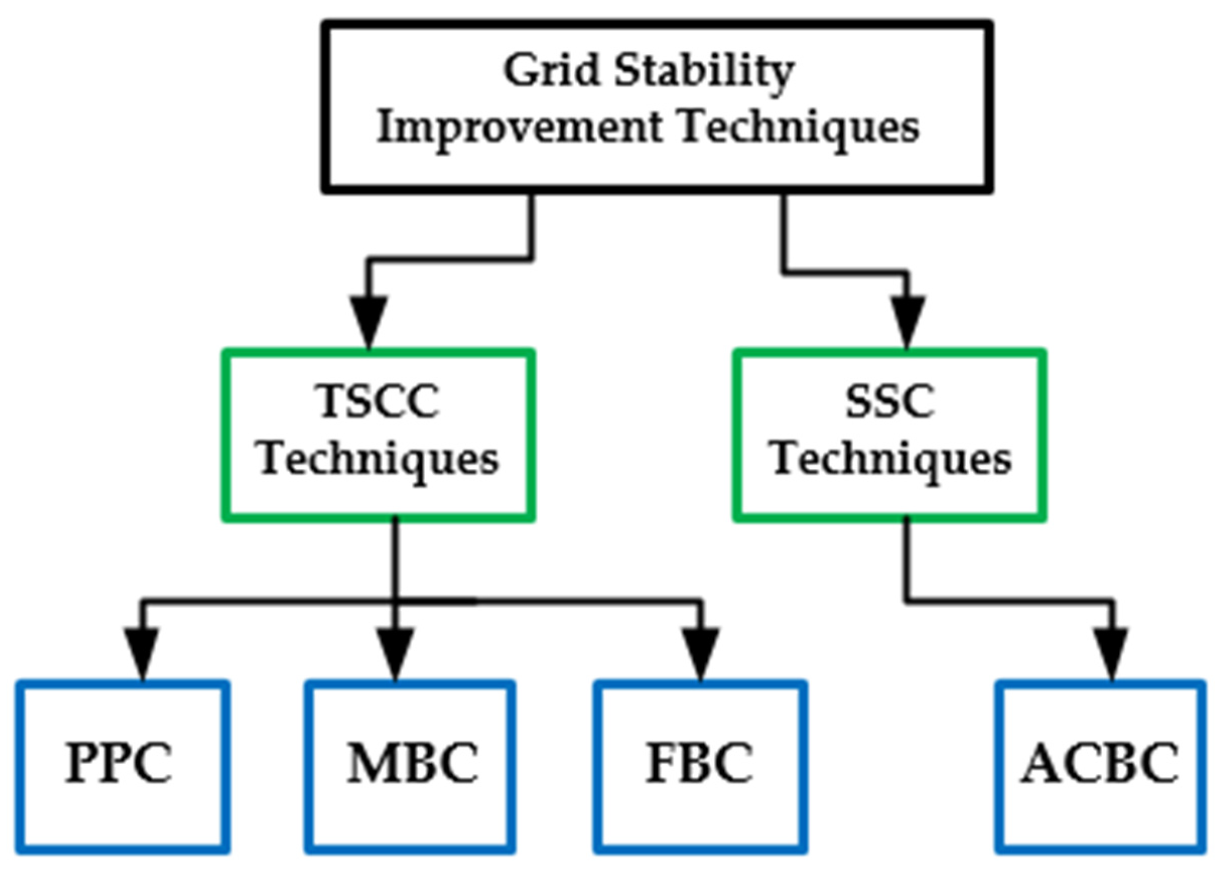
2. TSCC Grid Stability Improvement Techniques

As is known, the nearest converter to the grid at the PCC is the rectifier converter. This converter can be required for power delivery, voltage mitigation improvement, or frequency stability depending on the applied control strategy. The second converter is referred to as the DC-DC converter, which helps in amplifying and adjusting the DC voltage requirement of the EV FCS and the provision for galvanic isolation where necessary [38]. The TSCC strategy, as observed in the literature, is implemented at the rectifier stage of the FCS [39,40]. The TSCC strategy is characterized by different control techniques depending on the supply source at the rectification stage [40]. It utilizes either the current control, direct power control or voltage-oriented control approach [41]. For a three-phase source, it achieves direct-quadrature-zero (dq0) from the abc signal through the alpha-beta-zero (αβ0) Clarke transformation in a fixed reference frame, and through the αβ0-to-dq0 transformation in a rotating reference frame [41]. In a single-phase converter, dq0 can be directly converted into the αβ frame without any matrix transformation [42]. In this case, an imaginary variable is obtained by shifting the original voltage and current signal by 90°, where the original and imaginary signals now represent load current in αβ coordinates [43].
Notably, dq0 is referred to as the tensor that rotates the reference frame of a three-element vector [43]. On the other hand, αβ0 is the simplification of a three-phase system into a mathematical transformation for analysis purposes [42]. However, in mitigating grid instability, such as with switching transient, current harmonics and power losses, most control strategies, as mentioned in [32,40], have been acknowledged to have grid frequency fluctuation and voltage sag issues caused by an increased number of EV loads at the PCC [44]. Appreciable efforts for controlling the fundamental positive component of currents have been dedicated in [22,23]. To eliminate grid instability, some control improvement strategies are often deployed at the rectification stage in TSCC techniques. Therefore, the various control techniques applied for improving grid stability in rectifier converter control in TSCC will be discussed in the following subsections.

2.1. Partial Power Control (PPC) Technique

This technique is implemented in the rectification stage for voltage gain improvement and high efficiency [45], as shown in Figure 8a. The instantaneous power and voltage components are matched for a stable DC-link voltage and to synchronize grid current and voltage for the same phase and frequency alignment at the PCC [46]. Grid current (iabc) is deployed for current control implementation in the rotating direct-quadrature (dq) reference frame [46]. The DC-to-DC converter control is implemented using an isolated or non-isolated converter in this strategy, where the phase shift between the voltages, duty ratio (D) of the voltages, and the frequency of operation can be controlled using either a PI or DB controller for transient DC current reduction, as shown in Figure 8b [47]. The inner-loop current’s reference value (In) is generated by the first PI controller and is compared with the reference current (I*) in the inner-loop control, and this is fed to the second PI controller to generate the switching pulse to stabilize the DC output voltage [36]. The technique only processes a fraction of the total power requirement percentage of the EV load [45,46,47].
The implementation of partial power control using the PI controller in [36] and the DB controller in [23] for isolated converters showed a high surge current, which caused a slow response and poor efficiency in terms of reactive power control issues and complex control architecture. In contrast, the non-isolated power converter approach with the DB controller was adjudged to improve the overall voltage and frequency regulation at the PCC due to the absence of the isolation barrier, as well as improving the overall efficiency [47]. However, the problems of slow controller response and sensitivity to EV load changes, as expressed in [36,48], are major limitations of PI and DB controllers for PPC.

2.2. Mode-Based Control (MBC) Technique

This strategy is achieved in the rectification stage by using voltage-oriented control to apply a discontinuous control signal to maintain the dynamics of FCS control when variations happen to the EV load [49]. In order to keep the input power factor at unity, the inner loop uses MBC to regulate the direct and quadrature components of the line current in the rectification stage [50]. At the same time, the PI controller is used with the MCB strategy to regulate the DC-link voltage at the reference value in the DC-to-DC converter stage, as shown in Figure 9. This approach incorporates the input voltage feedback signal [49,50]. This feedback signal is used to provide a reasonable level of control effect whenever there are sudden changes in FCS operation [51]. It disallows the transient component of oscillation by preventing the slow response caused by changes in the load pattern at the PCC [52]. The MBC strategy is characterized by its ability to lower the transient characteristics and increase the system’s stability under nonlinear load circumstances [49,50]. However, the MCB strategy has been reported in [50,52] to show negative incremental impedance at a constant EV load, and this will compromise the FCS and grid stability at the PCC. In a related development, the observation in Figure 9 shows that  I d *  and  I q *  are the controller’s reference current values for the direct (d) and quadrature (q) components, respectively, with respect to the reference direct current ( V d c * ) values. In view of this drawback in MBC, filter-based control is often seen as a viable alternative and this will be discussed in Section 2.3.

2.3. Filter-Based Control (FCB) Technique

This control strategy is executed in the rectification stage via either hysteresis or voltage-oriented control, depending on the type of filter [35,53]. This concept was applied in [54] for a three-phase supply to improve the system’s resistance to harmonic grid voltage and unbalanced loads in the rectification stage. However, this strategy is sometimes unable to respond to practically opposite circumstances during voltage tracking [55]. To overcome this challenge, as shown in Figure 10a, the double second-order generalized integrator-frequency locked loop (DSOGI-FLL) algorithm was used to calculate the grid voltage based on the measurement of grid voltages (VGabc) [56]. Similarly, in the DC-to-DC stage, this control strategy managed the power exchange between the DC-link voltage and the EV battery by comparing the output load current (IBat) and the reference load current (IBat*) to give the switching control signal to the DC-to-DC converter, as shown in Figure 10b [53]. In the DC-to-DC stage, a filter may also be deployed to reduce the switching noise that returns to the power source, as well as the high-frequency noise that comes from the power supply [55]. The first positive sequence harmonics components of the grid voltage’s amplitude (|V1|) and angles (θa, θb, θc) are computed to guarantee the transformation of load currents for each converter phase individually [53,54,55].
The current component in this case ( i α x  and  i β x ) were transformed using θa, θb and θc. The components  i d x   a n d   i d q  are helpful to achieve the correct values of reference currents in the coordinate system of synchronous rotation. Converter currents ( i C a , i C b , i C c ) are measured by the current control loop [54], and the converter’s reference voltage values were VcaRef, VcbRef, and VccRef, respectively. The α current components of the phase ( i α a , i α b , i α c ) helped to realize the converter’s reference currents ( i C a R e f , i C b R e f , i C c R e f ) through the current control loop [55]. To achieve this goal, this approach is based on modifications to the direct-quadrature (dq) method for single-phase circuits. The conversion to synchronously rotating dq coordinates for each phase separately, as in Expression (1), serves as the starting point for reference current computations [56]:
i d i q = sin ω 1 t c o s ( ( ω 1 t ) cos ω 1 t s i n ( ω 1 t ) i α i β
where  i α  and  i β  are generated directly from the current of each phase, and the current is shifted by one-quarter of the fundamental time (T), as expressed in (2) [54,55,56]:
i α i β = i t i ( t T / 4 )
when the waveform  cos ω 1 t  is synchronized with the phase voltage, the dq current components constitute average terms and variables in time, which can be expressed as in Expression (3) [56]:
i d i q = ı d + ı ~ d ı q + ı ~ q
where  i d  and  i q  are dq current components in d and q, respectively, and the fundamental harmonics of active power and reactive power in the specified phase are caused by the average current component in the d-axis given at  ı d = i m ( 1 ) cos φ  and  ı q = i m ( 1 ) sin φ , where  φ  is phase-shift angle and  i m ( 1 )  is the first harmonic of maximum current [54]. To satisfy the specified conditions, the higher harmonics of the  i d  and  i q  current components that change with time must be filtered [57]. In the case of an active filter, the harmonic component is subtracted from the distorted grid current from the filtered fundamental component of current using the traditional hysteresis control approach [58]. The switching frequency is limited within a specific band to achieve the best response to the distorted grid current at the PCC [58]. However, there are some shortcomings of FBC, as reported in [56,57,58], and some of the most recent state-of-the-art achievements in the TSCC strategy are discussed in the next subsection.

2.4. Summary of the Most Recent State-of-the-Art Achievements in TSCC Strategy

Recent achievements in [59,60] showed the robustness of PPC’s ability to process a portion of the individual battery’s charging power. This strategy ensures a dependent relationship between the partial voltage (VP) processed and FCS output current by adjusting the closed-loop dynamic regulation [61,62] to aid the injection of the required current during FCS operation at the unitary power factor [63,64]. The recent contributions in [65,66] for MBC showed its superiority over other conventional techniques in terms of its ability to transform the source phases’ current or voltage directly, as opposed to the stationary frame’s current or voltage pattern in FCS [67,68]. This strategy provides control robustness and rejection of the matched voltage disturbance at the PCC during FCS operation, through the voltage feedback loop [69,70]. In the FBC development, the reports in [57,71] presented a new approach for harmonics reduction, circulating current reduction and reactive power regulation. This strategy incorporates the DSOGI-FLL algorithm to ensure voltage stability at the PCC during FCS operation [72,73]. Table 1 presents a comparison of the contributions for and drawbacks of TSCC techniques for FCS from the literature. Despite the recent reported contributions for the TSCC strategy in [23,59], SSC control techniques offer a more robust strategy, and this will be discussed in Section 3.

3. SSC Grid Stability Improvement Techniques

This control strategy is deployed in the single stage converter of the FCS [23,44]. This approach uses only a rectifier for the desired output voltage [57,74]. This strategy is used where control simplicity and component count reduction are desired [59,74]. It traditionally allows a mixture of either feedforward, feedback, direct power or current control strategy, which regulates the grid-side instantaneous current and voltage using a single rectifier [75]. The alternating-current-based control technique is discussed in the next subsection.

3.1. Alternating-Current-Based Control (ACBC) Technique

One of the examples of SSC control techniques is shown in Figure 11. This technique consists of a rectifying converter [74] that is implemented to mimic the virtual synchronous machine’s (VSM) behavior [76]. However, the report in [77] proposed an interleaved switching strategy for rectifier control using the PI controller for current control to ensure the reduction in the magnitude of the ripple current injection. This strategy achieved a harmonic distortion reduction in grid-side currents and had a ripple-free DC-side current without sacrificing the efficiency of the FCS [77,78]. Conversely, the report in [22] proposed the DC-side voltage integration with time filtering of the instantaneous value of current control for grid-side harmonic cancellation at the PCC. The report in [20] proposed an independent single control variable of the grid sinusoidal current waveforms for injected power and voltage regulation at the PCC. This was achieved by extracting the grid phase angle using the dq transformation of input voltages and the output DC voltage tracking control strategy [79].
In a related development, the authors in [78] presented a different control approach for DC-link voltage and ripple current cancellation for the rectifier DC output. This control strategy was able to maintain the soft switching of both AC-side and DC-side switches across the voltage grid cycle at the PCC for different load conditions [75,78]. However, a major drawback of a slow response was observed in [74,78] under increased EV loads, but this shortcoming was suggested to be due to the PI controller [74,75,76]. In the case of VSM, as shown in Figure 12, where it is deployed to mimic a VSM’s performance, it offers a controlled power factor and stabilized supply frequency irrespective of changes at the PCC [80]. This control strategy ensures frequency and power control by using the virtual amplitude compensator (VAC) [81]. This approach is often deployed with a PI controller to achieve a margin of stability in a weak grid scenario via the virtual shaft angle with frequency adaptation, and to update the filter coefficient of synchronous frequency for frequency regulation at the PCC [82].
The VSM control strategy can also be implemented through other approaches, such as the line impedance approach [83]. The line impedance approach helps to reshape the quadrature axis with positive resistance in the lower frequency band to ensure regulated frequency at the PCC [82,84]. However, it must be applied by feedforwarding both the direct and quadrature axes’ grid voltages with respect to the reference current [84]. Additionally, the tracking of zero steady-state errors and the damping of the torsion oscillation of the system must be achieved at a predetermined frequency [83,84]. In addition, the virtual flux control (VFC) strategy was used in [85] for direct power control and input voltage source estimation for a three-phase-based FCS to regulate line current harmonics, the DC-link voltage output, and the power factor through the control of the instantaneous active power and the reactive power at the input [85]. Additionally, the authors in [86] presented the virtual harmonic impedance (VHI) strategy to mitigate spikes in switching harmonics and voltage. This strategy implements a current controller in the rectification stage of the FCS to avoid power losses, while exhibiting the behavior of a real impedance, as shown in Figure 13 [87]. It creates an equal output impedance to resistance and inductance [88,89]. In this case, the virtual harmonic impedance, ( Z V s ), is the sum of virtual harmonic resistance and virtual inductance [89]:  E s  is the input and  i o ( s )  is the output current parameter, while  P s  is the transfer function and  Z V  is virtual harmonic impedance [87]. Despite the power factor improvement, direct power, and frequency control in this SSC strategy, it presents some very serious issues related to power losses and frequency fluctuation, as reported in [77,87], during multiple FCS operations at the PCC, and this call for further research. Some of the most recent achievements and contributions in SSC control techniques are summarized in the next subsection.

3.2. Summary of the Most Recent State-of-the-Art Achievements in SSC Strategy

The most recent approaches in the ACBC strategy were presented in [80,90]. This strategy allows for virtual amplitude compensation (VAC) at the rectification stage of the FSC [91,92]. In this case, the voltage amplitude was maintained within a standard of allowable margin by the VSM controller to fast-track power control of the EV battery charging process [93,94]. It ensured that reactive power flowed towards the grid in such a way that the amplitude of the reference current vector was adaptable to the FCS’ power rating regardless of the grid condition [80,95]. Similarly, [86,89] presented the concept of virtually varying the effective line impedance at the harmonic frequency in such a way that the influence of mismatched line impedance on nonlinear FCS load distribution was reduced [96,97]. This strategy avoids losses, while mimicking the behavior of real impedance [87,88]. Additionally, the latest approach in [98] proposed the implementation of the flux compensation strategy at the rectification stage of the FCS through direct power control [98,99]. This approach helps to regulate line current harmonics, power factor and DC-link voltage by controlling instantaneous active power and reactive power input [85,100]. This strategy also allows for the synchronization of the voltage of the FCS rectifier with the voltage condition at the PCC [101].
A comparison of the various contributions for and drawbacks of SSC control techniques from the literature is shown in Table 2. A detailed highlight of the issues with and various limitations of TSCC techniques for rectifier control for FCS stability is discussed in Section 4.

4. Issues with TSCC Techniques for Rectifier Control for FCS Stability

The issues with the TSCC strategy arise from the approaches of constant voltage charging and constant current charging [39,102]. Constant voltage charging allows the charger’s entire current to flow into the EV battery until the power supply meets the pre-set voltage value [102]. In contrast, the constant current charging approach adjusts the output voltage of the FCS with the EV battery to keep the current constant, to prevent an overcurrent charging condition [24]. The major drawbacks of using the PI controller are maximum deviation, a longer response time, and a longer oscillation period [39] whenever the EV load increases at the FCS. The PR controller is often deployed at the rectification stage of the FCS [103] in order to eliminate the steady-state error at the chosen resonant frequency with the generated infinite gain [39]. This controller only allows the filtering of low-order harmonics by choosing the right frequency at the rated value [104]. The only exception is when the PR controller is applied in the DC-to-AC stage in the bidirectional converter for the vehicle-to-grid (V2G) application of the FCS, because of its ability to handle the power factor angle and grid current control.
Despite this advantage of the PR controller’s ability to effectively reduce the current ripple at twice the line frequency [105], the reports in [105,106] showed that the stability of the PR controller depends on the resonant coefficient, the cut-off frequency and the proportional coefficient. Therefore, the various issues associated with TSCC techniques, such as the PPC technique, are discussed in the next subsections.

4.1. Issues with PPC Technique

A major defect reported for the PPC technique is the unbalanced series of power flow and voltage level control between the source and the EV load [107]. The static voltage gain has a direct impact on the PPC’s processed power ratio, as explained in [107]. Therefore, the PPC strategy may not be suitable when there is a significant step-up or step-down between the source voltage and the FCS [23]. In addition, the application of isolated converters for the PPC approach is constrained by reactive power control issues [46]. On the other hand, in the non-isolated PPC structure, the converter power injected fundamentally decreased as the voltage gain approached unitary, due to the absence of the isolation barrier, as discussed in [108]. There were reported issues of high switching losses, noise, durability issues and a decrease in efficiency as the load increased at the PCC, possibly due to the absence of galvanic isolation between the source and the FCS, which is a major requirement for the FCS application [36]. This is because it is difficult for the PPC to eliminate the effects of common-mode voltage differences created by ground loops [46]. This ground loop problem causes unwanted current to flow between the rectification stage and the DC-to-DC stage during FCS power exchange [108].
Additionally, the DB controller has been reported to exhibit an oscillating output when used for the PPC approach [108,109]. The issue of steady-state offset due to its strong sensitivity to model parameters and measurement noise is a major limitation, as stated in [109]. Therefore, issues of maximum deviation, narrow bandwidth and longer response times required to unwind the error signal in most conventional controllers are limitations worthy of mention, as observed in [108,110].
PPC parameter performances are presented in Table 3. The investigations conducted in [23,45,46,59,62,111] indicated converter-side control as the major strategy for the PPC architecture, as shown in Table 3. The authors in [23,45] deployed the DB controller, while the authors in [46,59,62] used the PI controller. The authors in [23,45,62] concentrated their efforts on voltage and current control, unlike the authors in [46,59,111], whose interest was only in current control. There were no estimated values of power factor (PF) or current total harmonic distortion (CTHD) in [46] to justify the 66.6% efficiency obtained, as shown in Table 3. In addition, there were no reported CTHD values for the works carried out in [23,46,111], but the CTHD values for [45,59,62] were obtained as 4.62%, 8.32%, and 7.527%, respectively.
The PF values obtained in [23,111] were 0.94 and 0.93, respectively. Additionally, the authors in [23,45,59,62,111] achieved power factors of 4.94%, 0.91%, 0.97%, 0.89%, and 0.93%, respectively, with efficiency values of 95.5%, 99.62%, 98.77%, and 99.5% achieved in [23,59,62,111], respectively. Despite claims of high efficiency by the authors in [23,59,62,111], their CTHD values were quite above the recommended standard in IEEE Std. 519, except in [45], where the PPC model improved (IM). The reported grid impact in [23,59,62] agreed that the PPC models were unstable under multiple EV loads. The PPC strategy basically allowed for the improvement of FCS efficiency, as observed in the values obtained in [23,59,62], especially under a single EV load. However, PPC may not be suitable if there is a significant variation in the voltage at the PCC or in a weak grid scenario during multiple FCS operations [46].

4.2. Issues with the MBC Technique

The MBC technique is characterized by grid voltage sag issues [112], especially in the multiple-EV FCS scenario, as presented in [112]. Furthermore, it is prone to excessive input current at considerably higher duty cycles [113] due to the converter’s circuit configuration. The report in [114] suggested that primary switches’ high voltage spikes, occasioned by leakage inductance in the transformer, caused voltage and frequency fluctuations at the PCC. Similarly, there is a tendency for complications of mismatched line impedance with higher-capacity EV loads, as reported in [50]. This is because of the unwanted current in the FCS network in the PI controller, which focuses on the zero-sequence circulating current control architecture [115]. The PID controller was used in [116,117] for improving the harmonic effect and power factor in the rectification stage of FCS control. The closed-loop control strategy in the DC-to-DC converter stage for the feedback signal helps to make adjustments in the output voltage for a fast-charging response. The report in [117] observed some drawbacks of the PID controller, which were a narrow range of stability, a long settling time at the steady state and the amplification of high-frequency noise.
The parameter performances of MBC are shown in Table 4. The investigation conducted in [20] used the PID controller for inner-loop control and outer-loop control, while the authors in [52,112,114] used the PI controller for inner-loop control and the authors in [50] used the PR controller for inner-loop control and outer-loop control, as given in Table 4. The authors in [20,50,52,112,114] achieved PF values of 0.987, 0.990, 1.0,0.88, and 0.924, respectively, with CTHD values achieved in [20,50,52,114] as 4.8%, 3.7%, 3.4%, and 50.67%, respectively. There was no available CTHD value in [112] nor efficiency values in [52,112], but the efficiency values in [20,50,114] were 94.5%, 95.3%, and 94.3%, respectively. In [114], the CTHD value was above the recommended standard in IEEE Std. 519. It is imperative to note, considering the authors in [50,114], that regardless of their impressive CTHD values, these strategies were acknowledged to be unstable under multiple EV loads by their respective authors. Furthermore, the report in [52] showed an improved controller performance with a unitary power factor, but this performance requires further investigation due to the lack of information regarding the efficiency value. MBC offers the FCS controller the strategy of mitigating external disruptions and unforeseen grid voltage adjustments by providing a leading power factor, as observed in [50,52]. However, the PF and CTHD values obtained in [112,114] showed that MBC was unable to withstand the complication of unmatched impedance in a higher-capacity FCS due to the challenges of complex control circuitry in MBC, as reported in [112,114].

4.3. Issues with FBC Technique

For the FBC approach to TSCC, this strategy was constrained at a lower-frequency switching range [118]. There was a reported issue of synchronism between the converter units due to the triplen harmonics created in the units as a result of variations in the grid voltage, as shown in some of the values obtained for CTHD in [119]. The strategy may fail to provide the regulation of voltage and frequency to the EV load at the PCC because of the complexity of the controller’s structure [118]. Additionally, the report in [118] showed that the effectiveness of active damping, the repetitive controller, and multiple resonant controllers is not guaranteed as a viable option for filter-based control during multiple fast-charging operations [52]. Admittedly, the challenge of finding the exact input signal, which must be applied to the system to achieve a steady-state output within the smallest number of time steps, is a limitation of this strategy, especially when deployed with the PI controller [19]. Moreover, the application of the DB controller for the FBC strategy in [120] achieved voltage balancing in the rectification stage, obtaining zero current error at the sampling instant when tracking the signal of the desired phase currents by generating the corresponding switching signals for the rectifier [120]. Therefore, the effect of the time delay must be considered in the DC-to-DC converter of the FCS in the current-mode closed-loop switching strategy to give a high control-output signal at a finite settling time [109].
The FBC’s overall parameter performances are tabulated in Table 5. The table showed that the PI controller was deployed in [95,121] for current control and voltage control, and the DB controller was used in [19] for current control and voltage control. The PID controller was deployed in [119] for current control, voltage control, and power control, and the PR controller was used in [122] for current control and voltage control. The authors in [19,95,119,121,122] were able to achieve PF values of 0.7, 1.0, 0.828, 1.0, and 0.9, with corresponding values of CTHD of 4.68%, 2.34%, 24.82%, 14.6%, and 4.8%, respectively. It is important to note that the authors in [95,121] achieved unitary PF values, which could be attributed to the grid support offered by the double close loop control in [95] and the energy support system (ESS) in [121]. The CTHD and PF values in [119] were quite outside the recommended values of IEEE Std. 519 of ≤5% for CTHD and ≥0.9 of power factor.
The grid impact examined by the authors in [19,119,121] proved their models’ non-stability under multiple EV loads. The improvement observed in [121] was achieved through the compensation of DC-link voltage variation caused by changes in the grid voltage variation at the PCC in the rectification stage. However, during numerous FCS operations, the FBC’s complex structural design hinders the controller’s ability to react to lower-frequency switching, and this presents challenges for the controller to respond to any sudden changes in grid voltage at the PCC [95].

5. Issues with SSC Control Techniques for Rectifier Control for FCS Stability

SSC control techniques are characterized by issues of frequency fluctuation, voltage sag, and inner control loop disturbances [77]. There are reports of high grid current and switching losses whenever the system’s switching frequency is increased [77]. The challenge of slow current feedback emanating from the decrease in output voltage as EV load increases at the PCC is demonstrated in [22]. The SSC control’s application with VSM techniques has shown the limitation of the SSC control acting as a voltage source under a nonlinear EV load with active-power balancing issues [74,86]. The various issues with the ACBC technique of SSC control are discussed in the subsequent subsection.

5.1. Issues with the ACBC Technique

The performance of the VHI strategy often results in harmonic-resistance tracking issues [123], stability margin issues and grid voltage deterioration at the PCC upon any slight changes in grid frequency resulting from additional EV loads, as reported in [124]. The application of the VHI approach in the ACBC strategy often drives the quadrature-axis impedance within the lower-frequency band to cause a decrease in grid current. This often results from any increase in the grid voltage due to sudden load profile changes for phase-lock loop (PLL) synchronization [22,83]. The limitation reported in the virtual flux compensation (VFC) approach for any sudden increase in the FCS load at the PCC was the corresponding voltage drop at the grid side [82,86]. Additionally, the VHI approach had a major drawback of susceptibility to frequency disturbance under the weak grid condition, and it often required extra frequency derivatives with significant control burden [74,82]. This made the VHI act as a voltage source under nonlinear EV load, thereby complicating and degrading the active power component of the FCS in the stability margin and possibly causing grid voltage sags [86]. ACBC’s ability to improve grid stability during multiple FCS operations at the PCC may lead to power and frequency oscillation issues with excessive under- and over-voltage at the PCC under weak grid conditions [82].
The performance comparison of the ACBC techniques is presented in Table 6. The observation of Table 6 shows that the authors in [80,83,94,125] used the PI controller for inner loop current control. The control techniques in [80,85] concentrated on current and frequency as the control parameters, while [83,125] controlled the model using current and voltage as the control parameters, whereas the report in [94] laid more emphasis on frequency as the control parameter. The authors in [80,83,85,94] achieved the unitary value of PF, while [125] achieved 0.9999 for PF. CTHD values of 5.0%, 2.9%, 12.3%, and 1.394% were obtained in [80,85,94,125], respectively, as shown in Table 6. The CTHD value in [83] was not reported. The authors in [80,83,85,94,125] obtained efficiency values of 85.5%, 90.1%, 87.3%, 74.9%, and 95.7%, respectively. It is imperative to note that the grid impact in [80] showed that the model was only stable for a single EV load (SFSL), whereas the reports in [85,94] speculated that grid impact improved despite achieving CTHD values above the recommended value of ≤5% for IEEE Std. 519 [94].

5.2. Performance Evaluation of TSCC and SSC Control Techniques

Even though satisfactory performance has been reported for single-stage converter (SSC) control techniques regarding grid instability reduction [14], this control strategy has shown a major drawback of slow current feedback when slight changes in grid frequency occur [126]. It shows poor disturbance-rejection ability and slow responses to abrupt changes to grid voltage variation when additional FCS loads are added, as reported in [123,126]. In addition, there are reported cases of dead-times and modulation delays, which result in high grid currents during fast-charging operations [126]. There was no international rule-based order for grid stability convention for estimating the exact minimum or the least requirement for a particular improvement technique in the generality of the research literature under examination. Moreover, the general representation given by the reviewed literature commentary is of grid stability being improved, enhanced or stable for a single EV load and, in some cases, unstable under multiple EV loads. Going forward, in view of the power factor and CTHD as the standard parameters, authors have concluded that the SSC control technique with frequency control and VHI control using the PI controller is adjudged to achieve the maximum grid stability value in the control loop architecture, as observed in the literature.
Regrettably, this conclusion is hasty and fails to address the PI controller’s major inadequacies, as shown in Table 6. The relatively high performances recorded in [80,81,82,83] were constrained and degraded by PI defects, which were not limited to higher maximum deviation. The problems of longer response time and associated frequency oscillation at the PCC during multiple FCS operations are also worthy of mention, as observed in [25,115,122]. The authors’ inability in [80,83] to estimate the efficiency achieved in the FCS scenario, as well as grid impact and CTHD, requires further research on the suitability of these techniques in FCS operation.
Therefore, in consideration of the comparison established in Table 1, Table 2, Table 3, Table 4, Table 5 and Table 6 for TSCC and SSC control strategies, it is imperative to summarize the various research gaps observed in the literature that motivated the authors to pursue these studies, as follows:
  • Transient switching issues and slow controller dynamic responses during multiple FCS operations;
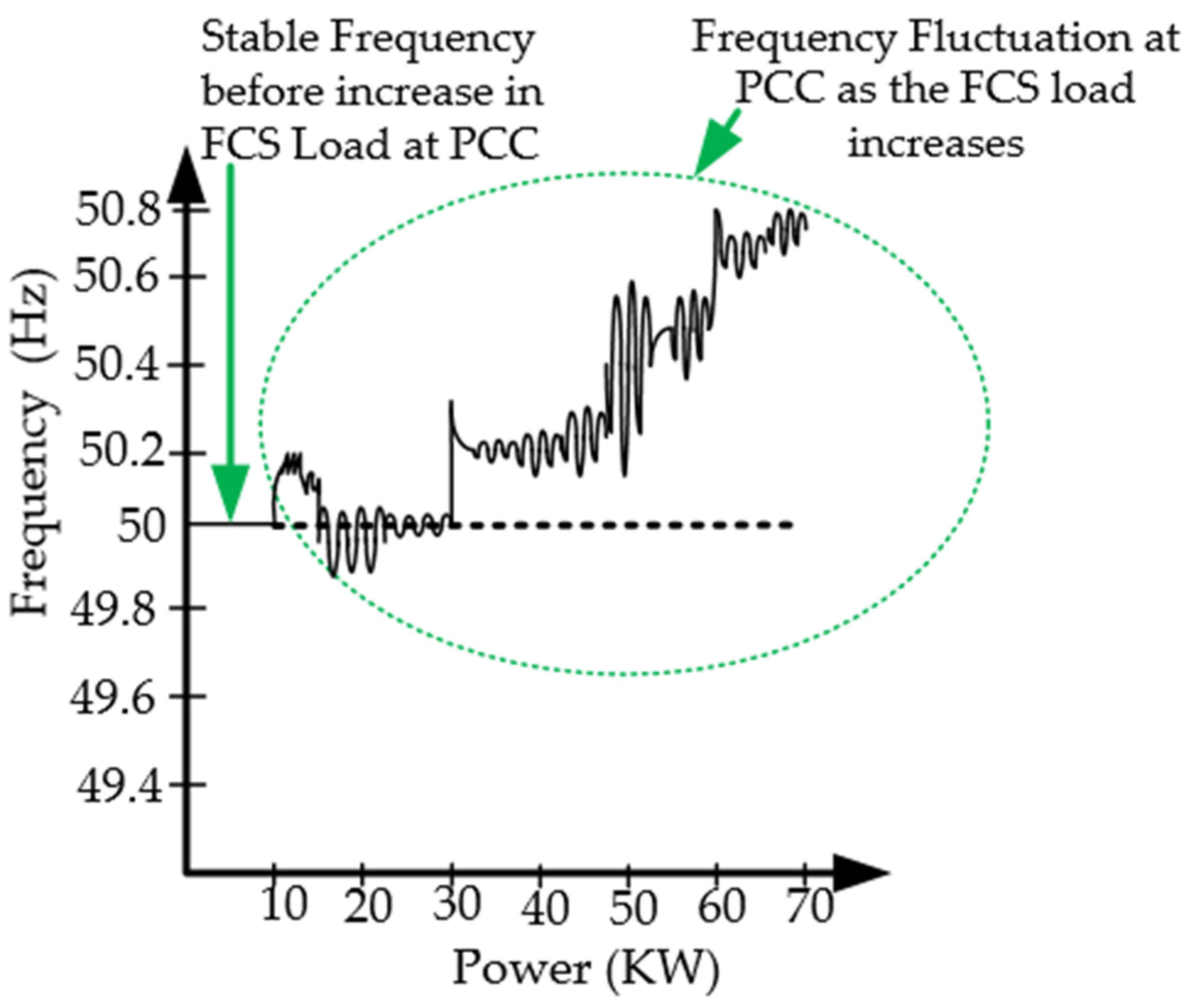
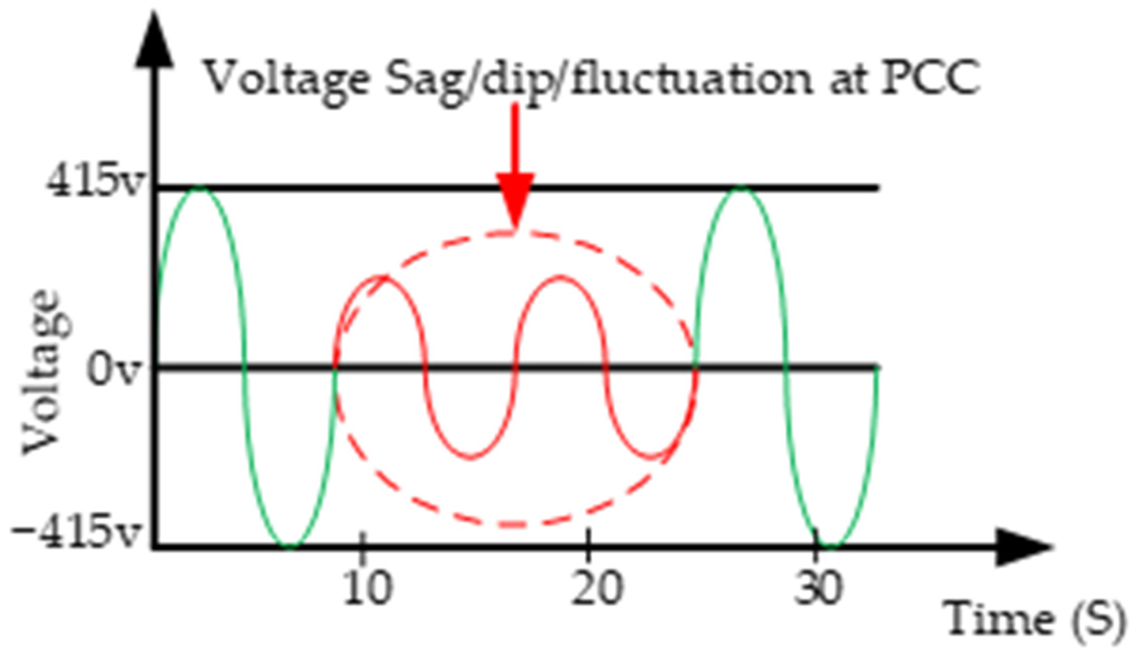
  • Power exchange instability and frequency fluctuation issues during multiple FCS operations at the PCC;
  • Negative incremental impedance at constant EV loads and harmonic distortion losses at a higher FCS capacity of above 50 kW at the PCC.
Consequently, the integration of the energy storage system structure in the EV fast-charging operation represents a dynamic alternative in grid stability purification for achieving a nominal stability of grid frequency [127]. However, the massive cost implication and the intermittent nature of the energy storage system’s state of charge require further research, as stated in [128]. Despite the redundant power elimination capacity and the accompanying lower switching frequency demonstrated in [46,62], the EV FCS still largely culminated in a multiplicative integer in the fundamental frequency of the supplied power [128]. Contrarily, the performances reported in [23,59,94,119,121] were a reflection of the disturbance experienced in the singular EV fast-charging scenario, as indicated in the obtained efficiency and improved power factor values. The dynamism in the EV charging schematization warrants the vigilant monitoring of the grid frequency component and total harmonic distortion values for conformity with the IEEE standard [59,89]. The FCS voltage requirement, power capacity and power factor values during the EV fast-charging operation are necessary parameters for estimating the efficiency of the FCS. Furthermore, the need for grid stability improvement examination under the most stringent conditions calls for double attention [94,119]. Figure 14 presents the relationship between voltage requirement, efficiency and power capacity that can be achieved for the FCS. It clearly shows that voltage requirement plays a significant role in increasing the efficiency and output power of the FCS.
More importantly, the power factor and CTHD values obtained from the considered literature for TSCC techniques present some CTHD values quite above the minimum recommended value, with the corresponding power factor as the recommended standard. Consequently, there are options for improving these values towards the minimum acceptable power factor and CTHD values. Relatedly, the values of power factor and CTHD push the system towards its stability limit [89,119]. This is because of the background harmonics introduced along the feedforward path whenever the grid voltage is distorted as a result of multiple-EV fast charging [22], and when coupled with the steady-state error in the stationary frame, this will have a significant negative impact on the grid when the controller fails to perform and, in some cases, when increasing the proportional gain is recommended. This proves TSCC to be unsuitable for multiple EV fast-charging operations [22,89]. However, some of the most commonly discussed issues in the literature for grid stability improvement for FCS [89,94,95,96,97,98,99,100,101,102,103,104,105,106,107,108,109,110,111,112,113,114,115,116,117,118,119,120,121,122,123,124,125,126,127,128], as presented in Figure 15, identified the direction for future FCS controller strategies for grid stability improvement.
Interestingly, overcoming the various controller challenges under increasing FCS load at the PCC requires a new idea regarding the VSM with EV battery state-of-charge integration control, and this is discussed in the next section.

6. Concept of Virtual Synchronous Machine-Based State of Charge Feedback Control

The VSM is a new concept for improving FCS-based technology that can be implemented at the rectification stage of the FCS in order to imitate the functionality of the conventional synchronous machine [81,129]. Active power and reactive power control, rapid frequency fluctuation, and VSM’s other functional restrictions have all been studied by various scholars in the literature [76,82], although the VSM is far more adaptable and simpler to use than the synchronous machine. In comparison with other conventional controllers, the VSM controller offers a lot more versatility and a swift response because its settings may be changed in real time [95]. However, due to the high degree of FCS penetration in the grid, the rotational inertia of the power grid is decreased [76]. Therefore, to compensate for frequency fluctuation, as well as for active power and reactive power balancing, a control strategy is proposed for the future, as shown in Figure 16. Achieving this VSM control strategy in the FCS requires some modifications and consideration of the EV battery’s state of charge (SOC) with some VSM equations. The VSM’s mechanical rotating part ( θ ¨ ) and the electromotive force (e) due to rotor movement are given by Expressions (4) and (5), respectively [76,82]:
θ ¨ = 1 J ( T e T m D p θ ˙ )
e = M f i f θ ˙ i a b c sin θ a b c M f d i f d t cos θ a b c
such that J represents the rotating part’s moment of inertia,  T m  represents mechanical torque, and  T e  represents electromagnetic torque, which is dependent on rotor current I and virtual rotor angle  θ , where  θ ˙  is virtual angular speed. Therefore,  T e  is given in Expression (6) by [76]:
T e = M f i f i a b c sin θ a b c
where  M f i f ,  is field excitation, which is dependent on the generated signal from the grid voltage parameter. Hence, this strategy also takes into consideration active power (P) and reactive power (Q) equations, as shown in Expressions (7) and (8), respectively:
P = θ ˙ M f i f i a b c sin θ a b c
Q = θ ˙ M f i f i a b c cos θ a b c
Recent advancements in SOC estimation have created the leverage for sophisticated battery management systems for maximized power conversion operations [130]. This is because the SOC allows the right amount of charge (Y) for the EV battery, preventing overcharging and discharging (X) of the EV battery [131]. The EV battery capacity ( C n T ), current (I) and Coulombic efficiency ( η z ) of the EV at the reference SOC value ( Z t o ) at normal temperature (T) will influence FCS performance [131]. The effect of SOC on the grid will generate a huge charging power over a longer period of time, and this will cause a rise in voltage deviation, frequency swings, line loss and peak demand [132]. More importantly, the improper control of the SOC or a higher initial SOC value will prolong the charging process [132,133]. It is important to note, in this regard, that an EV battery’s SOC is vulnerable to the effects of self-discharge, aging and charge and discharge current, which might impede the balancing of power and voltage of the FCS [131].
Therefore, the EV FCS controller also depends on the linkage of the interface between the power converters and the grid system [40,134]. Hence, prolonged the overcharging and discharging of the EV battery may compromise the SOC of the battery with corresponding voltage sags and frequency fluctuations at the PCC [135]. The generalized state of charge ( S O C t ) with respect to temperature is given in Expression (9) [131,132,133,134], and the SOC under charge and discharge conditions are given in Expression (10) [132,133].
S O C t = Z t o + t o t η z i C n T d t
SOC = 0 X Y X Y 1 = 0 S O C X X S O C Y Y < S O C 1
where  Z t o  is the reference SOC value at full charge with respect to normal temperature,  C n T  is the maximum battery capacity,  η z  is Coulombic efficiency, I is battery current and t is temperature. As is known, X is the discharging battery limit condition and Y is the charging battery limit condition in the operating state.
The proposed strategy can be adapted to the virtual inertia of the VSM controller in accordance with the EV battery’s SOC condition by using the current SOC value to decide the current functioning state of the EV battery to prevent overcharging or overdischarging. It can provide an adaptation to the system inertia for any transient change in grid frequency, voltage, and power injection caused by any additional EV loads at the PCC, and help to minimize the impact of the FCS on the grid. In addition, the torque generated from the motor can respond to changes in power flowing from the AC source, and with a constant load the strategy will give a high power factor at the AC source, while also being able to control the DC voltage [82].
In addressing the identified research gaps in this paper, the authors proposed the following contributions as regards the proposed strategy, as follows:
  • A droop-based technique with the SOC feedback strategy for adaptable EV battery charge and discharge limit conditions;
  • An adaptation to the system inertia for the active power and reactive power decoupling strategy for any transient changes in grid frequency, voltage, and power regulation at the PCC for a higher-rated FCS capacity of above 50 kW at the PCC;
  • Adaptability to the strategy of the SOC instantaneous functioning state of the EV battery to aid in the controller’s fast, dynamic and transient response under multiple FCS operations.

7. Future Studies and Development

In addition to the proposed strategy’s advantages, VSM-based techniques will play a more superior ancillary control support role in FCS controller design in the near future. Additionally, the future development of FCS controller algorithms will be channeled beyond sustaining and preserving frequency, voltage and power exchange consistency at critical moments during FCS operation. Therefore, the effects of grid instability and decreased power quality during EV fast-charging operations are precursors to the failure of centralized control and to standardized VSM-based interface and model implementation. More importantly, the authors of this paper proposed the following worthy future research directions in FCS controller design:
  • An artificial-intelligence-based VSM controller with harmonic impedance compensation for inertial and load profile adaptability to the EV FCS charging condition;
  • A neural-network-based VSM controller with the amplitude compensation strategy for inertia improvement and for the management of the EV battery discharge condition.

8. Conclusions

Grid stability improvement techniques in FCS are an emerging control concept for eliminating the impact of the insensitivity of the state of charge (SOC) of EV batteries in FCS due to voltage and frequency deviations at the point of common coupling (PCC) during multiple FCS operations. Consequently, via the proposed control approach, the FCS controller can provide ancillary support services, guaranteeing grid voltage, frequency, and power stability at the PCC under multiple FCS operations. In this paper, various grid stability solutions available in the literature have been analyzed, compared, and categorized as TSCC or SSC control to show their various types, methods, contributions, issues, performance evaluation, and drawbacks. Therefore, to highlight the strategies’ main peculiarities, Table 1, Table 2, Table 3, Table 4, Table 5 and Table 6 have been actuated in terms of the latest contribution and the efficiency, power factor, and total harmonic distortion (CTHD) values against the recommended IEEE Std. 519. TSCC techniques are the earliest methods deployed, either as PPC, MBC, or FBC for the current or voltage control strategy for controlling the EV battery’s SOC during charging using proportional-integral (PI), proportional-resonant (PR), deadbeat, or proportional-integral-derivative (PID) controllers, but their performances are limited due to major drawbacks associated with the TSCC strategy, which include a slow transient response, high current harmonics, frequency fluctuation, a longer charging time, and switching losses due to transient switching, to mention a few.
However, there are currently few research studies on SSC control techniques, despite their superiority in performance and their ability to provide a simple structure, as well as auxiliary support and inertia support through the virtual synchronous machine (VSM) strategy. The techniques have some drawbacks, of power decoupling and dynamic response problems. In due consideration of the reports reviewed in Section 2 and Section 3, as well as Table 3, Table 4, Table 5 and Table 6, it is obvious that the smallest value of current total harmonic distortion (CTHD) and the closest power factor value to unitary were attained when there was auxiliary support, such as with the VSM, integrated into the FCS controller for grid stability improvement, unlike when grid stability repercussion was disregarded. Additionally, when developing a controller for the FCS, the impact of the state of charge with respect to the instantaneous active power exchange of the EV battery must be carefully taken into account. Consequently, the authors of this paper proposed and gave an independent hypothesis as a direction for further research by blending the method of the SSC control technique with the state-of-charge feedback control strategy to provide frequency adaptation and support to respond to any disturbances in active power as the battery reaches its SOC voltage limit. Therefore, the authors of this paper suggest the SSC control technique of the VSM with the state-of-charge feedback consideration to give readers a direction for further research.

Author Contributions

Conceptualization, K.M. and S.A.Z.; validation, P.K., F.R.S.S. and A.N.A.; resources, F.R.S.S., P.K., A.V.-I. and A.N.A.; writing—original draft preparation, K.M. and S.A.Z.; writing—review and editing, and funding acquisitions, K.M., S.A.Z., F.R.S.S., P.K., A.N.A. and A.V.-I. All authors have read and agreed to the published version of the manuscript.

Funding

This work was supported and financed thanks to monetary assistance from the Universiti Tun Hussein Onn Malaysia at UTHM Publisher’s Office via Publication Fund E15216, the Zurich University of Applied Sciences and the Research Partnership Grant ASEAN 2022 under the grant RPG_ASEAN_0702022_13.

Data Availability Statement

Not applicable.

Acknowledgments

The authors would like to also acknowledge the Malaysian International Scholarship, the Ministry of Higher Education Malaysia (MOHE), Unversiti Tun Hussien Onn Malaysia, the Advanced Control in Power Converter research group and the Zurich University of Applied Science for essential assistance.

Conflicts of Interest

The authors have no conflict of interest.

References

  1. Mogos, A.S.; Grillo, S. Impact of EV Charging Stations in Power Grids in Italy and Its Mitigation Mechanisms. In Proceedings of the 21st IEEE International Conference on Environment and Electrical Engineering and 2021 5th IEEE Industrial and Commercial Power System Europe, Bari, Italy, 7–10 September 2021. [Google Scholar] [CrossRef]
  2. Chaudhary, V.K. Deployment Impact of Electric Vehicle Charging Stations on Radial Distribution System. In Proceedings of the IEEE 9th Uttar Pradesh Section International Conference on Electrical, Electronics and Computer Engineering, Allahabad, India, 2–4 December 2022. [Google Scholar]
  3. Cai, S.; Kirtley, J.L.; Lee, C.H.T. Critical Review of Direct-Drive Electrical Machine Systems for Electric and Hybrid Electric Vehicles. IEEE Trans. Energy Convers. 2022, 37, 2657–2668. [Google Scholar] [CrossRef]
  4. Camurca, L.; Pereira, T.; Hoffmann, F.; Liserre, M. Analysis, Limitations and Opportunities of Modular Multilevel Converter-Based Architectures in Fast Charging Station Infrastructure. IEEE Trans. Power Electron. 2022, 37, 10747–10760. [Google Scholar] [CrossRef]
  5. Almeida, M.; Chaves, M.; Morgado, S.; Louro, M. Effects of EV Ultra-Fast Chargers in Power Quality. In Proceedings of the 2022 CIRED Workshop on E-Mobility and Power Distribution Systems, Porto, Portugal, 2–3 June 2022. [Google Scholar]
  6. Nazih, Y.; Abdel-moneim, M.G. A Ring-Connected Dual Active Bridge Based DC-DC Multiport Converter for EV Fast-Charging Stations. IEEE Access 2022, 10, 52052–52066. [Google Scholar] [CrossRef]
  7. Habib, H.U.R.; Waqar, A.; Hussien, M.G.; Junejo, A.K.; Jahangiri, M.; Imran, R.M.; Kim, Y.S.; Kim, J.H. Analysis of Microgrid’s Operation Integrated to Renewable Energy and Electric Vehicles in View of Multiple Demand Response Programs. IEEE Access 2022, 10, 7598–7638. [Google Scholar] [CrossRef]
  8. Arias, N.B.; Hashemi, S. Electric Vehicles: Recent Status, Challenges, and Future Prospects. IEEE Trans. Intell. Transp. Syst. 2019, 20, 1–20. [Google Scholar]
  9. Safayatullah, M.; Elrais, M.T.; Ghosh, S.; Rezaii, R.; Batarseh, I. A Comprehensive Review of Power Converter Topologies and Control Methods for Electric Vehicle Fast Charging Applications. IEEE Access 2022, 10, 40753–40793. [Google Scholar] [CrossRef]
  10. Sahoo, G.K. Recent Trends and Topology of Electric Vehicle Charging through DC Microgrid. In Proceedings of the 2022 IEEE Delhi Section Conference, New Delhi, India, 11–13 February 2022. [Google Scholar]
  11. El Bakkari, F.; Mounir, H.; El Marjani, A. Electric Vehicle Progress and Challenges on the Road to Sustainable Transportation. In Proceedings of the 2021 International Renewable and Sustainable Energy Conference, Tetouan, Morocco, 23–27 November 2021. [Google Scholar] [CrossRef]
  12. Zulkifli, S.A.; Momoh, K. Grid Stability Improvement for Charging Stations of EV Battery During V2G. IEEE Smart Grid Bull. Compend. 2022, 18–19. [Google Scholar]
  13. Mahfouz, M.M.; Iravani, R. Autonomous Operation of the DC Fast-Charging Station. IEEE Trans. Ind. Electron. 2022, 69, 3787–3797. [Google Scholar] [CrossRef]
  14. Aretxabaleta, I.; Alegría, I.M.D.E.; Andreu, J.O.N. High-Voltage Stations for Electric Vehicle Fast-Charging: Trends, Standards, Charging Modes and Comparison of Unity Power-Factor Rectifiers. IEEE Access 2021, 9, 102177–102194. [Google Scholar] [CrossRef]
  15. Karmaker, A.K.; Hossain, A.; Pota, H.R.; Onen, A. Energy Management System for Hybrid Renewable Energy-Based Electric Vehicle Charging Station. IEEE Access 2023, 11, 27793–27805. [Google Scholar] [CrossRef]
  16. Salama, H.S.; Said, S.M.; Vokony, I.; Hartmann, B. Adaptive Coordination Strategy Based on Fuzzy Control for Electric Vehicles and Superconducting Magnetic Energy Storage—Towards Reliably Operating Utility Grids. IEEE Access 2021, 9, 61662–61670. [Google Scholar] [CrossRef]
  17. Tu, H.; Feng, H.; Srdic, S.; Lukic, S. Extreme Fast Charging of Electric Vehicles: A Technology Overview. IEEE Trans. Transp. Electrif. 2019, 5, 861–878. [Google Scholar] [CrossRef]
  18. Shafiq, S.; Bin Irshad, U.; Al-Muhaini, M.; Djokic, S.Z.; Akram, U. Reliability Evaluation of Composite Power Systems: Evaluating the Impact of Full and Plug-in Hybrid Electric Vehicles. IEEE Access 2020, 8, 114305–114314. [Google Scholar] [CrossRef]
  19. Hoach, N.; Al-Sumaiti, A.S.; Al-Hosani, K.; Al-Jaafari, K.A.; El-Moursi, M.S.; Ji-Byon, Y.; Al-Sawalhi, J.Y. Enhanced Performance of Charging Stations via Converter Control under Unbalanced and Harmonic Distorted Grids. IEEE Trans. Power Deliv. 2021, 36, 3964–3976. [Google Scholar] [CrossRef]
  20. Blinov, A.; Zinchenko, D.; Rabkowski, J.; Wrona, G.; Vinnikov, D. Quasi Single-Stage Three-Phase Filterless Converter for EV Charging Applications. IEEE Open J. Power Electron. 2021, 3, 51–60. [Google Scholar] [CrossRef]
  21. Cortes, P.; Vancu, M.F.; Kolar, J.W. Swiss Rectifier Output Voltage Control with Inner Loop Power Flow Programming (PFP). In Proceedings of the 2013 IEEE 14th Workshop on Control and Modeling for Power Electronics, Salt Lake City, UT, USA, 23–26 June 2013. [Google Scholar] [CrossRef]
  22. Zhang, D.; Lin, H.; Zhang, Q.; Kang, S.; Lu, Z. Analysis, Design, and Implementation of a Single-Stage Multipulse Flexible-Topology Thyristor Rectifier for Battery Charging in Electric Vehicles. IEEE Trans. Energy Convers. 2019, 34, 47–57. [Google Scholar] [CrossRef]
  23. Iyer, V.M.; Gulur, S.; Gohil, G.; Bhattacharya, S. An approach towards extreme fast charging station power delivery for electric vehicles with partial power processing. IEEE Trans. Ind. Electron. 2020, 67, 8076–8087. [Google Scholar] [CrossRef]
  24. Paul, S. Deadbeat Control of Linear and Non Linear System using Signal Correction Technique. MAYFEB J. Electr. Comput. Eng. 2017, 2, 1–23. [Google Scholar]
  25. Anzola, J.; Aizpuru, I.; Arruti, A. Non-Isolated Partial Power Converter for Electric Vehicle Fast Charging Stations. In Proceedings of the 2020 IEEE 11th International Symposium on Power Electronics for Distributed Generation Systems, Dubrovnik, Croatia, 28 September–1 October 2020. [Google Scholar] [CrossRef]
  26. Ahmed, I.; Rehan, M.; Basit, A.; Tufail, M.; Hong, K. A Dynamic Optimal Scheduling Strategy for Multi-Charging Scenarios of Plug-in-Electric Vehicles over a Smart Grid. IEEE Access 2023, 11, 28992–29008. [Google Scholar] [CrossRef]
  27. Abdelrahim, A.; Smailes, M.; Ahmed, K.H.; Member, S.; Mckeever, P. New Fault Detection Algorithm for an Improved Dual VSM Control Structure With FRT Capability. IEEE Access 2021, 9, 125134–125150. [Google Scholar] [CrossRef]
  28. Sehimi, Y.; Sakly, J.; Almaksour, K.; Robyns, B. A Novel Fast Charger Architecture with Reduced Impact on Distribution Grids Based on V2V Power Transfer. In Proceedings of the 2021 IEEE Vehicle Power and Propulsion Conference, Gijon, Spain, 25 October–14 November 2021. [Google Scholar] [CrossRef]
  29. Zulkifli, S.A. Electric Vehicle Charging Station: Cause and Solution to Grid System. IEEE Smart Grid Bull. Compend. 2019, 5–7. [Google Scholar]
  30. Basit, A.; Ahmad, T.; Ali, A.Y.; Ullah, K.; Mufti, G.; Hansen, A.D. Flexible modern power system: Real-time power balancing through load and wind power. Energies 2019, 12, 1710. [Google Scholar] [CrossRef]
  31. Husain, I.; Islam, M.S.; Gurpinar, E.; Yu, W.; Xue, L.; Sahu, R. Electric Drive Technology Trends, Challenges, and Opportunities for Future Electric Vehicles. Proc. IEEE 2021, 109, 1039–1059. [Google Scholar] [CrossRef]
  32. Boonraksa, T.; Paudel, A.; Dawan, P.; Marungsri, B. Impact of Electric Bus Charging on the Power Distribution System a Case Study IEEE 33 Bus Test System. In Proceedings of the 2019 IEEE Grand International Conference and Exposition Asia, Bangkok, Thailand, 19–23 March 2019; pp. 819–823. [Google Scholar] [CrossRef]
  33. Hong, Y.J.; Jeong, Y.W.; Chung, C.C. Grid voltage modulated direct power control for output smoothing in battery energy storage systems. In Proceedings of the 2020 International Conference on Control, Automation and Systems, Busan, Republic of Korea, 13–16 October 2020; pp. 335–338. [Google Scholar] [CrossRef]
  34. Hattam, L.; Greetham, D.V.; Haben, S.; Roberts, D. Electric vehicles and low-voltage Grid: Impact of uncontrolled demand side response. In Proceedings of the 2017 24th International Conference & Exhibition on Electricity Distribution, Glasgow, UK, 12–15 June 2017. [Google Scholar] [CrossRef]
  35. Syed, J.J.; Nasi, A.; Jamian, R. Harmonic Distortion Improvement Considering Bulk Charging Station and Distributed Generation. In Proceedings of the 2020 IEEE International Conference on Power and Energy, Penang, Malaysia, 7–8 December 2020. [Google Scholar]
  36. Bhaskar, M.S.; Ramachandadaramurthy, V.K.; Padmanaban, S.; Blaabjrg, F.; Ionel, D.M.; Almakhles, D. Survey of DC-DC non-isolated topologies for unidirectional power flow in fuel cell vehicles. IEEE Access 2020, 8, 178130–178166. [Google Scholar] [CrossRef]
  37. Trimboli, M.S.; De Souza, A.K.; Xavier, M.A. Stability and Control Analysis for Series-Input/Parallel-Output Cell Balancing System for Electric Vehicle Battery Packs. IEEE Control Syst. Lett. 2022, 6, 1388–1393. [Google Scholar] [CrossRef]
  38. Aswathi, C.P.; Lakshmiprabha, K.E. An improved full bridge DC-DC converter for electric vehicles. Int. J. Technol. Eng. Syst. 2014, 6, 89–94. [Google Scholar]
  39. Chinta, N.K. Comparison of PI and AI Controllers used For Dc-Dc Converter for EV Fast Charging. J. Crit. Rev. 2020, 7, 1290–1298. [Google Scholar] [CrossRef]
  40. Lipu, M.S.H.; Faisal, M.; Ansari, S.; Hannan, M.A.; Karim, T.F.; Ayob, A.; Hussain, A.; Miah, M.S.; Saad, M.H.M. Review of electric vehicle converter configurations, control schemes and optimizations: Challenges and suggestions. Electronics 2021, 10, 477. [Google Scholar] [CrossRef]
  41. Wang, N.; Wang, C.; Niu, Y.; Yang, M.; Yu, Y. A Two-Stage Charging Facilities Planning Method for Electric Vehicle Sharing Systems. IEEE Trans. Ind. Appl. 2021, 57, 149–157. [Google Scholar] [CrossRef]
  42. Peng, L.; Ma, L.; Song, W.; Liu, H. Reference-input-based imaginary axis current estimation method for DQ control strategy of single-phase PWM converters. CSEE J. Power Energy Syst. 2022, 2, 1–9. [Google Scholar] [CrossRef]
  43. Mnider, A.M.; Atkinson, D.J.; Dahidah, M.; Armstrong, M. A simplified DQ controller for single-phase grid-connected PV inverters. In Proceedings of the 2016 7th International Renewable Energy Congress, Hammamet, Tunisia, 22–24 March 2016. [Google Scholar] [CrossRef]
  44. Shao, C.; Qian, T.; Wang, Y.; Wang, X. Coordinated Planning of Extreme Fast Charging Stations and Power Distribution Networks Considering On-Site Storage. IEEE Trans. Intell. Transp. Syst. 2021, 22, 493–504. [Google Scholar] [CrossRef]
  45. Sundararaman, K.; Alagappan, P.; Elavarasu, R. Partial processing converters for charging electric vehicles. In Proceedings of the 2021 1st International Conference on Advances in Electrical, Computing, Communications and Sustainable Technologies, Bhilaj, India, 19–20 February 2021. [Google Scholar] [CrossRef]
  46. Anzola, J.; Aizpuru, I.; Arruti, A.; Alacano, A.; Artal-Sevil, J.S.; Lopez, R.; Bernal-Ruiz, C. Partial power processing-based charging unit for electric vehicle extreme fast charging stations. In Proceedings of the 2020 IEEE Vehicle Power and Propulsion Conference, Gijon, Spain, 26–29 October 2020. [Google Scholar] [CrossRef]
  47. Artal-Sevil, J.S.; Bernal-Ruiz, C.; Bono-Nuez, A. Partial Power Processing architecture applied to a Battery Energy Storage System. In Proceedings of the 2020 IEEE Vehicle Power and Propulsion Conference, Gijon, Spain, 18 November–16 December 2020. [Google Scholar] [CrossRef]
  48. Suresh, K.; Bharatija, C.; Chellammal, N.; Tarq, M.; Chakrabortty, R.K.; Ryam, M.J.; Alamri, B. A Multifunctional Non-Isolated Dual Input-Dual Output Converter for Electric Vehicle Applications. IEEE Access 2021, 9, 64445–64460. [Google Scholar] [CrossRef]
  49. Sivaraman, P.; Logeswaran, T.; Sakthi Surya Raj, J.S.; Boopathimanikandan, S. Design and Analysis of Sliding Mode Control for Battery Charging Applications. In Proceedings of the 2020 IOP Conference Series: Materials Science and Engineering, Ulaanbaatar, Mongolia, 10–13 September 2020. [Google Scholar] [CrossRef]
  50. Choi, S.; Oh, S.; Kim, M.; Lee, I.; Lee, J. Interleaved Isolated Single-Phase PFC Converter Module for Three-Phase EV Charger. IEEE Trans. Veh. Technol. 2020, 69, 4957–4967. [Google Scholar] [CrossRef]
  51. Guerriero, P.; Coppola, M.; Lauria, D.; Daliento, S. PWM based sliding mode control of a fast charger for supercapacitors. In Proceedings of the 2020 International Symposium on Power Electronics, Electrical Drives, Automation and Motion, Sorrento, Italy, 24–26 June 2020. [Google Scholar] [CrossRef]
  52. Drobnic, K.; Grandi, G.; Hammami, M.; Mandrioli, R.; Ricco, M.; Viatkin, A.; Vujacic, M. An Output Ripple-Free Fast Charger for Electric Vehicles Based on Grid-Tied Modular Three-Phase Interleaved Converters. IEEE Trans. Ind. Appl. 2019, 55, 6102–6114. [Google Scholar] [CrossRef]
  53. Cittanti, D.; Mandrile, F.; Bojoi, R. Optimal Design of Grid-Side LCL Filters for Electric Vehicle Ultra-Fast Battery Chargers. In Proceedings of the 2020 55th International Universities Power Engineering Conference, Torino, Italy, 1–4 September 2020. [Google Scholar] [CrossRef]
  54. Buła, D.; Jarek, G.; Michalak, J.; Zygmanowski, M. Control method of four wire active power filter based on three-phase neutral point clamped t-type converter. Energies 2021, 14, 8427. [Google Scholar] [CrossRef]
  55. Dharmakeerthi, C.H.; Mithulananthan, N.; Saha, T.K. Modeling and planning of EV fast charging station in power grid. In Proceedings of the IEEE Power and Energy Society General Meeting, San Diego, CA, USA, 22–26 July 2012; pp. 1–8. [Google Scholar] [CrossRef]
  56. Amin, M.R.; Zulkifli, S.A. A framework for selection of grid-inverter synchronization unit: Harmonics, phase-angle and frequency. Renew. Sustain. Energy Rev. 2017, 78, 210–219. [Google Scholar] [CrossRef]
  57. Celik, D.; Ahmed, H.; Meral, M.E. Kalman Filter-Based Super-Twisting Sliding Mode Control of Shunt Active Power Filter for Electric Vehicle Charging Station Applications. IEEE Trans. Power Deliv. 2022, 2, 1097–1107. [Google Scholar] [CrossRef]
  58. Elhassan, G.; Jackson, R.; Zulkifli, S.A.; Pathan, E.; Khan, M.H. A comprehensive review on time-delay compensation techniques for grid-connected inverters. Inst. Eng. Technol. Power Gener. 2020, 4, 251–266. [Google Scholar] [CrossRef]
  59. Anzola, J.; Aizpuru, I.; Arruti, A. Partial power processing-based converter for electric vehicle fast charging stations. Electron. 2021, 10, 260. [Google Scholar] [CrossRef]
  60. Andrade, J.M.; Coelho, R.F.; Lazzarin, T.B. Processing and D. Converters, Partial Power Processing and Efficiency Analysis of DC-DC Differential Converters. Energies 2022, 15, 1159. [Google Scholar] [CrossRef]
  61. Geetha, V.M.; Saravanan, S.; Swathisriranjani, M.; Satheesh, C.S.; Saranraj, S. Partial Power Processing Based Bidirectional Converter for Electric Vehicle Fast Charging Stations. J. Phys. Conf. Ser. 2022, 2325, 012028. [Google Scholar] [CrossRef]
  62. Rivera, S.; Pesantez, D.; Kouro, S.; Lehn, P.W. Pseudo-Partial-Power Converter without High Frequency Transformer for Electric Vehicle Fast Charging Stations. In Proceedings of the 2018 IEEE Energy Conversion Congress and Exposition, Portland, OR, USA, 23–27 September 2018. [Google Scholar]
  63. Hoffmann, F.; Person, J.; Andresen, M.; Liserre, M.; Freijedo, F.D.; Wijekoon, T. A Multiport Partial Power Processing Converter with Energy Storage Integration for EV Stationary Charging. IEEE J. Emerg. Sel. Top. Power Electron. 2022, 10, 7950–7962. [Google Scholar] [CrossRef]
  64. Rivera, S.; Rojas, J.; Kouro, S.; Lizana, R.; Renaudineau, H.; Dragicevic, T. Partial-Power Converter Topology of Type II for Efficient Electric Vehicle Fast Charging. IEEE J. Emerg. Sel. Top. Power Electron. 2022, 10, 7839–7848. [Google Scholar] [CrossRef]
  65. Errahimi, F.; Es-Sbai, N.; ElIdrissi, Z.; Cheddadi, Y. Robust integral sliding mode controller design of a bidirectional DC charger in PV-EV charging station. Int. J. Digit. Signals Smart Syst. 2021, 5, 137–151. [Google Scholar] [CrossRef]
  66. Saadaoui, A.; Ouassaid, M.; Maaroufi, M. Overview of Integration of Power Electronic Topologies and Advanced Control Techniques of Ultra-Fast EV Charging Stations in Standalone Microgrids. Energies 2023, 16, 1031. [Google Scholar] [CrossRef]
  67. Makeen, P.; Ghali, H.A.; Memon, S. Theoretical and Experimental Analysis of a New Intelligent Charging Controller for Off-Board Electric Vehicles Using PV Standalone System Represented by a Small-Scale Lithium-Ion Battery. Sustainalibity 2022, 14, 7396. [Google Scholar] [CrossRef]
  68. Polat, H.; Hosseinabadi, F.; Hasan, M.; Chakraborty, S.; Geury, T.; Baghdadi, M. A Review of DC Fast Chargers with BESS for Electric Vehicles: Topology, Battery, Reliability Oriented Control and Cooling Perspectives. Batteries 2023, 9, 121. [Google Scholar] [CrossRef]
  69. Mazhar, T.; Naz Asif, R.; Malik, M.A.; Nadeem, M.A.; Haq, I.; Iqbal, M.; Kamran, M.; Ashraf, S. Electric Vehicle Charging System in the Smart Grid Using Different Machine Learning Methods. Sustainability 2023, 15, 2603. [Google Scholar] [CrossRef]
  70. Wang, H.; Gan, C.; Ni, K.; Yu, Z.; Qu, R. Trajectory Control Strategy for Flux-Weakening Operation of SPMSM. IEEE Trans. Power Electron. 2023, 38, 2262–2274. [Google Scholar] [CrossRef]
  71. Tao, Y.; Qiu, J.; Lai, S.; Sun, X.; Zhao, J. Adaptive Integrated Planning of Electricity Networks and Fast Charging Stations Under Electric Vehicle Diffusion. IEEE Trans. Power Syst. 2023, 38, 499–513. [Google Scholar] [CrossRef]
  72. Shahjalal, M.; Shams, T.; Tasnim, M.N.; Ahmed, M.R.; Ahsan, M.; Haider, J. A Critical Review on Charging Technologies of Electric Vehicles. Energies 2022, 15, 8239. [Google Scholar] [CrossRef]
  73. Thangavel, S.; Deepak, M.; Girijaprasanna, T.; Raju, S.; Dhanamjayulu, C.; Muyeen, S.M. A Comprehensive Review on Electric Vehicle: Battery Management System, Charging Station, Traction Motors. IEEE Access 2023, 11, 20994–21019. [Google Scholar] [CrossRef]
  74. Blahnik, V.; Stepanek, J.; Jara, M.; Talla, J. Ultra-fast charging station for public transport vehicles. In Proceedings of the 2017 43rd Annual Conference of the IEEE Industrial Electronics Society, Beijing, China, 29 October–1 November 2017. [Google Scholar]
  75. Collin, R.; Miao, Y.; Yokochi, A.; Enjeti, P.; Von Jouanne, A. Advanced electric Vehicle Fast-Charging Technologies. Energies 2019, 12, 1839. [Google Scholar] [CrossRef]
  76. Ma, Z.; Zhong, Q.C.; Yan, J.D. Synchronverter-based control strategies for three-phase PWM rectifiers. In Proceedings of the 2012 7th IEEE Conference on Industrial Electronics and Applications, Singapore, 18–20 July 2012; pp. 225–230. [Google Scholar] [CrossRef]
  77. Ahmed, M.A.; Dasika, J.D.; Saeedifard, M.; Wasynczuk, O. Interleaved Swiss Rectifiers for Fast EV/PHEV Battery Chargers. In Proceedings of the 2014 IEEE Applied Power Electronics Conference and Exposition, Fort Worth, TX, USA, 16–20 March 2014. [Google Scholar]
  78. Kumar, M.; Pramanick, S.; Panigrahi, B.K. Reduction in Circulating Current With Improved Secondary Side Modulation, Isolated Current-Fed Half Bridge AC–DC Converter. IEEE Trans. Power Electron. 2021, 37, 5625–5636. [Google Scholar] [CrossRef]
  79. Ehsani, M.; Singh, K.V.; Bansal, H.O.; Mehrjardi, R.T. State of the Art and Trends in Electric and Hybrid Electric Vehicles. Proc. IEEE 2021, 109, 967–984. [Google Scholar] [CrossRef]
  80. Mandrile, F.; Cittanti, D.; Mallemaci, V.; Bojoi, R. Electric vehicle ultra-fast battery chargers: A boost for power system stability? World Electr. Veh. J. 2021, 12, 16. [Google Scholar] [CrossRef]
  81. Dong, W.; Liu, K.; Chen, L. A novel frequency-changer control strategy based on a virtual synchronous motor. CSEE J. Power Energy Syst. 2019, 5, 199–205. [Google Scholar] [CrossRef]
  82. Cheema, K.M.; Chaudyhary, N.I.; Tahir, M.F.; Mehmood, K.; Mudassir, M.; Kamran, M.; Milyani, A.H.; Elbarbary, Z.M.S. Virtual synchronous generator: Modifications, stability assessment and future applications. Energy Rep. 2022, 8, 1704–1717. [Google Scholar] [CrossRef]
  83. Fang, J.; Li, X.; Li, H.; Tang, Y. Stability Improvement for Three-Phase Grid-Connected Converters Through Impedance Reshaping in Quadrature-Axis. IEEE Trans. Power Electron. 2018, 33, 8365–8375. [Google Scholar] [CrossRef]
  84. Guan, Y.; Guerrero, J.M.; Zhao, X.; Vasquez, J.C.; Guo, X. A New Way of Controlling Parallel-Connected Inverters by Using Synchronous-Reference-Frame Virtual Impedance Loop—Part I: Control Principle. IEEE Trans. Power Electron. 2016, 31, 4576–4593. [Google Scholar] [CrossRef]
  85. Roslan, N.F. Control Strategy of Grid Connected Power Converter based on Virtual Flux Approach. Ph.D. Thesis, Universitat Politècnica de Catalunya, Barcelona, Spain, 2021. [Google Scholar]
  86. Roldán-Pérez, J.; Rodríguez-Cabero, A.; Prodanovic, M. Harmonic virtual impedance design for a synchronverter-based battery interface converter. In Proceedings of the 2017 6th International Conference on Renewable Energy Research and Applications, San Diego, CA, USA, 5–8 November 2017. [Google Scholar] [CrossRef]
  87. Mohammed, O.O.; Otuoze, A.O.; Salisu, S.; Ibrahim, O.; Rufa’i, N.A. Virtual synchronous generator: An overview. Niger. J. Technol. 2019, 38, 153–164. [Google Scholar] [CrossRef]
  88. Shin, D.; Lee, J.P.; Yoo, D.W.; Kim, H.J. Stability Improvement of Interleaved Voltage Source Inverters Employing Coupled Inductors for Grid-Connected Applications. IEEE Trans. Ind. Electron. 2015, 62, 6014–6023. [Google Scholar] [CrossRef]
  89. Bai, S.; Lukic, S.M. Unified active filter and energy storage system for an MW electric vehicle charging station. IEEE Trans. Power Electron. 2013, 28, 5793–5803. [Google Scholar] [CrossRef]
  90. Sang, W.; Guo, W.; Dai, S.; Tian, C.; Yu, S.; Teng, Y. Virtual Synchronous Generator, a Comprehensive Overview. Energies 2022, 15, 6148. [Google Scholar] [CrossRef]
  91. Muftau, B.; Fazeli, M. The Role of Virtual Synchronous Machines in Future Power Systems: A Review and Future Trends. Electr. Power Syst. Res. 2022, 206, 107775. [Google Scholar] [CrossRef]
  92. Mallemaci, V.; Mandrile, F.; Rubino, S.; Mazza, A.; Carpaneto, E.; Bojoi, R. A comprehensive comparison of Virtual Synchronous Generators with focus on virtual inertia and frequency regulation. Electr. Power Syst. Res. 2021, 201, 107516. [Google Scholar] [CrossRef]
  93. Yang, Z.; Mei, C.; Cheng, S.; Zhan, M. Comparison of Impedance Model and Amplitude-Phase Model for Power-Electronics-Based Power System. IEEE J. Emerg. Sel. Top. Power Electron. 2020, 8, 2546–2558. [Google Scholar] [CrossRef]
  94. Amorim, T.S.; Carletti, D.; Encarnacao, L.F. Enhanced Virtual Synchronous Generator with Harmonic Current Filtering Capability. In Proceedings of the Industrial Electron Conference, Vitória, Brazil, 4–7 October 2019. [Google Scholar]
  95. Yan, X.; Qin, F.; Jia, J.; Zhang, Z.; Li, X.; Sun, Y. Virtual synchronous motor based-control of Vienna rectifier. Energy Rep. 2020, 6, 953–963. [Google Scholar] [CrossRef]
  96. Sreekumar, P.; Khadkikar, V. A New Virtual Harmonic Impedance Scheme for Harmonic Power Sharing in an Islanded Microgrid. IEEE Trans. Power Deliv. 2016, 31, 936–945. [Google Scholar] [CrossRef]
  97. Ding, D.; Zhang, G.; Wang, G.; Mijatoviv, Z.N.; Gragicevic, T.; Xu, D. Impedance Reshaping for Inherent Harmonics in PMSM Drives With Small DC-Link Capacitor. IEEE Trans. Power Electron. 2022, 37, 14265–14279. [Google Scholar] [CrossRef]
  98. He, P.; Li, Z.; Jin, H.; Zhao, C.; Fan, J.; Wu, X. An adaptive VSG control strategy of battery energy storage system for power system frequency stability enhancement. Int. J. Electr. Power Energy Syst. 2023, 149, 109039. [Google Scholar] [CrossRef]
  99. Yusoff, N.A.; Razali, A.M.; Karim, K.A.; Sutikno, T.; Jidin, A. A concept of Virtual-Flux Direct Power Control of three-phase AC-DC converter. Int. J. Power Electron. Drive Syst. 2017, 8, 1776–1784. [Google Scholar] [CrossRef]
  100. Wang, A.; Zhang, J. An accurate active power sharing study in virtual flux angle droop method. In Proceedings of the 2017 43rd Annual Conference of the IEEE Industrial Electronics Society, Beijing, China, 29 December–1 January 2017. [Google Scholar]
  101. Bi, K.; Xu, Y.; Zeng, P.; Chen, W.; Li, X. Virtual Flux Voltage-Oriented Vector Control Method of Wide Frequency Active Rectifiers Based on Dual Low-Pass Filter. World Electr. Veh. J. 2022, 13, 35. [Google Scholar] [CrossRef]
  102. Güven, A.F.; Akbaşak, S.B. DC Fast Charging Station Modeling and Control for Electric Vehicles. Black Sea J. Sci. 2021, 1, 680–704. [Google Scholar] [CrossRef]
  103. Pan, L.; Zhang, C. Performance Enhancement of Battery Charger for Electric Vehicles Using Resonant Controllers. Energy Procedia 2017, 105, 3990–3996. [Google Scholar] [CrossRef]
  104. Jean-Pierre, G.; Beheshtaein, S.; Altin, N.; Nasiri, A. A Control Scheme for a DC Extreme Fast Charger with RMS Current Minimization. In Proceedings of the 2021 IEEE 12th International Symposium on Power Electronics for Distributed Generation Systems, Chicago, IL, USA, 28 June–1 July 2021. [Google Scholar] [CrossRef]
  105. Salimin, S.; Noor, A.F.B.M.; Jumaat, S.A. Proportional resonant current controller strategy in inverter application. Int. J. Power Electron. Drive Syst. 2019, 10, 2238–2244. [Google Scholar] [CrossRef]
  106. Seth, A.K.; Singh, M. Resonant controller of single-stage off-board EV charger in G2V and V2G modes. IET Power Electron. 2020, 13, 1086–1092. [Google Scholar] [CrossRef]
  107. Anzola, J.; Aizpuru, I.; Romero, A.A.; Loiti, A.A.; Lopez-Erauskin, R.; Artal-Sevil, J.S.; Bernal, C. Review of Architectures Based on Partial Power Processing for DC-DC Applications. IEEE Access 2020, 19, 103405–103418. [Google Scholar] [CrossRef]
  108. Dragicevic, T.; Vinnikov, D. Guest Editorial Special Issues on Topology Modeling, Control, and Reliability of Bidirectional DC/DC Converter in DC Microgrid. IEEE J. Emerg. Sel. Top. Power Electron. 2021, 9, 1188–1191. [Google Scholar] [CrossRef]
  109. Hosoyamada, Y.; Fujimoto, Y.; Yuzuhiara, I.; Kawamura, A. Individual Deadbeat Control for Three-Phase Interleaved Buck DC/DC Converters. IEEE Trans. Ind. Appl. 2020, 56, 5065–5074. [Google Scholar] [CrossRef]
  110. Rafi, M.A.H.; Bauman, J. A Comprehensive Review of DC Fast-Charging Stations with Energy Storage: Architectures, Power Converters, and Analysis. IEEE Trans. Transp. Electrif. 2021, 7, 345–368. [Google Scholar] [CrossRef]
  111. Liu, C.; Zhang, Z.; Andersen, M.A.E. An Efficient Voltage Step-up/down Partial Power. In Proceedings of the 2021 IEEE Workshop on Wide Bandgap Power Devices and Applications in Asia (WiPDA Asia), Wuhan, China, 25–27 August 2021. [Google Scholar]
  112. Hou, N.; Li, Y.; Quan, Z.; Li, Y.R.G.; Zhou, A. Unified Fast-Dynamic Direct-Current Control scheme for Intermediary Inductive AC-Link Isolated DC-DC Converters. IEEE Open J. Power Electron. 2021, 2, 383–400. [Google Scholar] [CrossRef]
  113. Leone, C.; Longo, M.; Brenna, M. Impact Analysis of Ultra-Fast Charging Station by Monte Carlo Simulation. In Proceedings of the 2020 IEEE International Conference on Environment and Electrical Engineering and IEEE Industrial and Commercial Power Systems Europe, Madrid, Spain, 9–12 June 2020. [Google Scholar] [CrossRef]
  114. Seyezhai, R.; Aarthi, V. Simulation and Implementation of AC-DC Interleaved Boost Converter with Voltage Multiplier for Phev. ICTACT J. Microelectron. 2016, 2, 247–253. [Google Scholar] [CrossRef]
  115. Elhassan, G.; Zulkifli, S.A.; Bevrani, H.; Momoh, K.; Iliya, S.Z.; Khan, M.H.; Jackson, R.; Ahmed, M. Deadbeat Current Control in Grid-Connected Inverters: A Comprehensive Discussion. IEEE Access 2022, 10, 3990–4014. [Google Scholar] [CrossRef]
  116. Madhuri, G.; Veena Madhuri, K.; Navya, M.; Panduranga Reddy, G. Fast Charging Electric Vehicle using Fuzzy Logic Controller. Int. J. Eng. Res. 2020, 9, 499–502. [Google Scholar] [CrossRef]
  117. Shahzad, M.I.; Iqbal, S.; Taib, S. LLC series resonant converter with PID controller for battery charging application. In Proceedings of the 2014 IEEE Conference on Energy Conversion, Johor Baharu, Malaysia, 13–14 October 2014. [Google Scholar]
  118. Patil, D.; Deepa, K. Harmonic Analysis of Grid Connected Electric Vehicles with Residential Load for Different Filters. In Proceedings of the International Conference on Innovative Computing Intelligent Communication and Smart Electrical Systems, Chennai, India, 24–25 September 2021. [Google Scholar]
  119. Rahman, S.; Imteaj, A.; Khan, I.; Amini, M.H. Cascaded Solid State Transformer Structure to Power Fast EV Charging Stations from Medium Voltage Transmission Lines. In Proceedings of the 2020 54th Asilomar Conference on Signals, Systems and Computers, Pacific Grove, CA, USA, 1–4 November 2020. [Google Scholar]
  120. Barrero-González, F.; Milanés-Montero, M.I.; González-Romera, E.; Romero-Cadaval, E.; Roncero-Clemente, C. Control strategy for electric vehicle charging station power converters with active functions. Energies 2019, 12, 3971. [Google Scholar] [CrossRef]
  121. Rivera, S.; Wu, B. Electric Vehicle Charging Station with an Energy Storage Stage for Split-DC Bus Voltage Balancing. IEEE Trans. Power Electron. 2017, 32, 2376–2386. [Google Scholar] [CrossRef]
  122. Verma, A.; Singh, B. AFF-SOGI-DRC Control of Renewable Energy Based Grid Interactive Charging Station for EV with Power Quality Improvement. IEEE Trans. Ind. Appl. 2021, 57, 588–597. [Google Scholar] [CrossRef]
  123. Gedara, P.; Champa, H.; Dharmakeerthi, H. Electric Vehicle Integration- Grid Stability Concerns and Countermeasures. Ph.D. Thesis, University of Queensland, Brisbane, Australia, 2014. [Google Scholar]
  124. Zhang, Y.; Xu, D.; Liu, J.; Gao, S.; Xu, W. Performance Improvement of Model-Predictive Current Control of Permanent Magnet Synchronous Motor Drives. IEEE Trans. Ind. Appl. 2017, 53, 3683–3695. [Google Scholar] [CrossRef]
  125. Da Camara, R.A.; Fernandez-Ramirez, L.M.; Praca, P.P.; De Oliveira, D.; Garcia-Trivino, P.; Sarrias-Mena, R. An Application of the Multi-Port Bidirectional Three-Phase AC-DC Converter in Electric Vehicle Charging Station Microgrid. In Proceedings of the 2019 IEEE 15th Brazilian Power Electronics Conference, Santos, Brazil, 1–4 December 2019. [Google Scholar]
  126. Nair, A.C.; Fernandes, B.G. Solid-State Transformer Based Fast Charging Station for Various Categories of Electric Vehicles with Batteries of Vastly Different Ratings. IEEE Trans. Ind. Electron. 2021, 68, 10400–10411. [Google Scholar] [CrossRef]
  127. Badawy, M.; Ahmed, A.; Sozer, Y.; Yi, P. Active THD reduction strategy for grid connected EV charging stations. In Proceedings of the 2013 IEEE Energy Technology Conference, Cleveland, OH, USA, 27 June 2013. [Google Scholar] [CrossRef]
  128. Ghorbani, M.J.; Atashpar, S.; Mehrafrooz, A.; Mokhtari, H. Nonlinear Loads Effect on Harmonic Distortion and Losses of Distribution Networks Nonlinear Loads Effect on Harmonic Distortion and Losses. In Proceedings of the International Power System Conference, Tehran, Iran, 31 October–2 November 2011. [Google Scholar]
  129. Ramirez, J.M.; Montalvo, E.T. Handling a back-to-back converter prototype by the virtual synchronous generator strategy. In Proceedings of the 2012 1st Conference on IEEE Power Technology, Madrid, Spain, 28 June–2 July 2021. [Google Scholar] [CrossRef]
  130. Shen, P.; Ouyang, M.; Lu, L.; Li, J.; Feng, X. The co-estimation of state of charge, state of health, and state of function for lithium-ion batteries in electric vehicles. IEEE Trans. Veh. Technol. 2018, 67, 92–103. [Google Scholar] [CrossRef]
  131. Zhang, Z.; Cheng, X.; Lu, Z.Y.; Gu, D.J. SOC Estimation of Lithium-Ion Battery Pack Considering Balancing Current. IEEE Trans. Power Electron. 2018, 33, 2216–2226. [Google Scholar] [CrossRef]
  132. Xu, W.; Xu, J.; Lang, J.; Yan, X. A Multi-Timescale estimator for lithium-ion battery state of charge and state of energy estimation using dual h infinity filter. IEEE Access 2019, 7, 181229–181241. [Google Scholar] [CrossRef]
  133. An, F.; Jiang, J.; Zhang, W.; Zhang, C.; Fan, X. State of Energy Estimation for Lithium-Ion Battery Pack via Prediction in Electric Vehicle Applications. IEEE Trans. Veh. Technol. 2022, 71, 184–195. [Google Scholar] [CrossRef]
  134. Kumar, S.; Usman, A. A review of converter topologies for battery charging applications in plug-in hybrid electric vehicles. In Proceedings of the 2018 IEEE Industry Applications Society Annual Meeting, New Delhi, India, 10–11 November 2018. [Google Scholar] [CrossRef]
  135. Wang, Q.; Gu, H.; Ye, M.; Wei, M.; Xu, X. State of Charge Estimation for Lithium-Ion Battery Based on NARX Recurrent Neural Network and Moving Window Method. IEEE Access 2021, 9, 83364–83375. [Google Scholar] [CrossRef]
Figure 1. Global yearly EV adoption forecast by Navigant Research [10,11].
Energies 16 03956 g001
Figure 2. Fast-charging station’s block diagram.
Energies 16 03956 g002
Figure 3. Typical fast-charging stations and their properties.
Energies 16 03956 g003
Figure 4. Frequency fluctuation at PCC as number of FCS loads increases [30].
Energies 16 03956 g004
Figure 5. Voltage sags at PCC as number of FCS loads increases [31].
Energies 16 03956 g005
Figure 6. Common grid stability improvement techniques for FCS [25,26,27,28,29,30,31,32,33].
Energies 16 03956 g006
Figure 7. Various categories of controllers used for FCS [35,36].
Energies 16 03956 g007
Figure 8. (a) Typical rectifier stage’s partial power control block diagram; and (b) typical DC-to-DC stage partial power Control block diagram [45,47]. Note: * is the voltage and current signals from the DC/DC converter.
Energies 16 03956 g008
Figure 9. Typical mode-based control block diagram for FCS [50]. Note: * is the reference value.
Energies 16 03956 g009
Figure 10. (a) Typical rectifier stage’s filter-based control block diagram for FCS. (b) Typical DC-to-DC stage’s filter-based control block diagram for FCS [54,55]. Note: * is the reference value.
Energies 16 03956 g010
Figure 11. Typical ACBC schematic control diagram [20,21,22]. Note: * is the generated signal from the PI controller.
Energies 16 03956 g011
Figure 12. Typical ACBC schematic diagram with VSM diagram [76,82]. Note: * is the reference value.
Energies 16 03956 g012
Figure 13. Control block diagram of VSM with impedance compensation [87,88,89].
Energies 16 03956 g013
Figure 14. Various requirements for FCS performance evaluation [94,95,96,97,98,99,100,101,102,103,104,105,106,107,108,109,110,111,112,113,114,115,116,117,118,119].
Energies 16 03956 g014
Figure 15. Typical issues with FCS controller strategies, as observed in the literature [89,90,91,92,93,94,95,96,97,98,99,100,101,102,103,104,105,106,107,108,109,110,111,112,113,114,115,116,117,118,119,120,121,122,123,124,125,126,127,128].
Energies 16 03956 g015
Figure 16. Proposed VSM [76] with the state-of-charge (SOC) feedback controller.
Energies 16 03956 g016
Table 1. Comparison of the most recent trends in TSCC techniques FCS.
No.Ref.StrategyAlgorithm ComplexityContributionDrawbacks
1[60,63]PPCVery highSingle-voltage feedback control in the DC mode; high power decoupling ability.Major problems of harmonic distortion losses, longer charging time and slow transient response.
2[61,64]PPCHighCascade control structure for battery current, voltage regulation and high output voltage from low-input voltage source in FCS control.Efficiency reduces significantly with higher ratings;
FCS above 50 KW and slow dynamics response.
3[65,66]MBCSimpleHighly adaptable to parameter variation in FCS operation.Not suitable for multiple FCS operation; switching and power losses problem.
4[67,68]MBCHighReduces switching losses; robustness against voltage disturbance.Frequency variation, power exchange instability problem; shows negative incremental impedance at constant EV load.
5[72,73]FBCVery HighReduces circulating current and harmonics; aids reactive power and voltage regulation.Frequency fluctuation and instability problem at higher FCS capacity above 50 KW.
Table 2. Comparison of the most recent trends in SSC techniques for FCS.
No.Ref.VSM TechniqueStrategyContributionDrawbacksControl Complexity
1[90]Synchronous generator (SG)-based modelVAC-PIAccurately simulates electromagnetic characteristics of SG and requires no frequency derivative synchronization.Possesses weak resistance to interference due to voltage open-loop control and numerical instability issues.Very high
2[80,91]Swing equation-based VAC-PIProvides frequency adaptability to sudden changes in load profile.Excitation control issues; prone to synchronous resonance; weak stability during multiple FCS operations.Simple
3[86,89]Droop-based techniqueVHI-PIAdaptable to changes in single FCS load and enhances stability of system.Power sharing accuracy depends on rectifier output and line impedance.Simple
4[88]Frequency–power response-basedVHI-PIProvides configurable
output impedance and highly suitable for weak grid operation.
Stability margins are reduced with higher values of virtual resistance and it is hard to regulate dynamics.High
5
[98,99]Frequency–power response-basedVFC-PIProvides fast response and frequency support in single FCS load.Drift and saturation
effect due to DC
offset in the
integrated signals
lag voltage by
90° phase shift.
Simple
6ProposedDroop-based
SOC technique
VSM-SOCAdaptability to EV battery SOC. Fast transient response. Active and reactive power decoupling.
Frequency and voltage regulation at PCC.
Adaptable to SOC charge and discharge limit condition. It allows current limiting capability.
NILSimple
Table 3. Parameter performances of PPC deployed by previous researchers for improving grid stability in EV FCS.
No.Refs.FCSRՂCCVCPCSCCTHDSFPFGIMT
1[23]3 Φ 170 kW95.5% DBDBI, VCS---50 kHz0.94 ---PSFM
2[45]3 Φ 60 kW---DBDBI, V CS4.62% 20 kHz 0.91 IMPSFM
3[46]3 Φ 150 kW 66.6%PIPIICS---20 kHz ------PSM
4 [59] 3 Φ 90 kW 99.62% PI---ICS8.32% 10 kHz 0.97 UUMLPWM
5 [62]3 Φ 70 kW98.77% PIPII, V CS 7.527% 10 kHz 0.89 UUMLPWM
6 [111]3 Φ 130 kW99.5% PI---ICS---100 kHz 0.93 UUMLPWM
Notes: FCSR: Fast-charging station rating, ղ: efficiency, CC: Current control, VC: Voltage control, PC: Parameter control, SC: Stability control, CS: Converter side, CTHD: Current total harmonic distortion, SF: Switching frequency, PF: Power factor GI: Grid impact, MT: Modulation technique, PI: Proportional-integral, PSM: Phase-shift modulation, PWM: Pulse-width modulation, PSFM: Phase shift and frequency modulation, DB: Deadbeat, I: Current, V: Voltage, ---: Data not available, UUML: Unstable under multiple EV load, IM: Improved,  ( η ) = e f f i c i e n c y = V c × I c V s × I S .
Table 4. Parameter performances of MBC deployed by previous researchers for improving grid stability in EV FCS.
No. Refs. FCSRՂSCPCICOCGCCTHDPFSFMTGI
1 [20] 3 Φ 50 kW94.5% CSI, V PIDPID10 A4.80% 0.987 75 kHz PWM---
2 [50]3 Φ 50 kW95.3% GSVPRPR59.8 A 3.72% 0.990 50 kHz FFCUUML
3 [52]3 Φ 150 kW---CSI, V PI------3.40% 1.0 16 kHzPWMIM
4 [112]3 Φ 50 kW ---CSI, V PI---------0.880 10 kHz FDDCUUML
5 [114]3 Φ 50 KW 94.3% CSIPI------50.67% 0.924 50 kHz PWMUUML
Notes: FCSR: Fast-charging station rating, ղ: efficiency, SC: Stability control, PC: Parameter control, IC: Inner control, OC: Outer control, GC: Grid current, CTHD: Current total harmonic distortion, PF: Power factor, SF: Switching frequency, MT: Modulation technique, GI: Grid impact, GS: Grid side, CS: Converter side, FFC: Feed forward compensator, I: Current, V: Voltage, PI: proportional-integral, PR: Proportional-resonance, PID: Proportional integral derivative, PWM: Pulse-width modulation, ---: Data Not available, IM: Improved, UUML: Unstable under multiple EV load, FDDC: Fast dynamic direct current,  ( η ) = e f f i c i e n c y = V c × I c V s × I S .
Table 5. Parameter performances of FBC deployed by previous researchers for improving grid stability in EV FCS.
No. Refs. FCSRFTCCVCPCՂGSPF CTHDMTGCSFGI
1 [19]3 Φ 50 kW RLDBDB---98.4% REB 0.7 4.68% NM36.5 A 50 kHz UUML
2 [95]3 Φ 100 kW LPI---PI 83.0% * DCLC1.0 2.34% SPWM--- 10 kHz IM
3 [119] 3 Φ 105 kWABPFPIDPIDPID95% --- 0.828 24.82% PWM37.6 A 50 kHz UUML
4 [121]3 Φ 50 kW RLPI PI------ESS1.0 14.6% SVM14.8 A ---UUML
5 [122]3 Φ 50 kW RLCPRPR --- ---REB0.9 4.8% PWM16.7 A 50 kHz IM
Notes: FCSR: Fast-charging station rating, FT: Filter type, CC: Current control, VC: Voltage control, PC: Power control,  η : Efficiency, GS: grid support, PF: Power factor, CTHD: Current total harmonic distortion, MT: Modulation technique, GC: Grid current, SF: switching frequency, GI: Grid impact, RL: Resistor-inductor, L: Inductor, *: estimated value, RLC: Resistor-inductor-capacitor, NM: Needs no modulation, DCLC: Double-closed-loop control, ABPF: Active bandpass filter, SVM: Space vector modulation, PI: proportional-integral, PID: Proportional-integral-derivative, PR: Proportional-resonance, DB: Deadbeat, PWM: Pulse-width modulation, SRFT: Synchronous reference frame technique, REB: Renewable-energy-based, ---: Data not available, ESS: Energy support system, UUML: Unstable under multiple EV loads, IM: Improved,  ( η ) = e f f i c i e n c y = V c × I c V s × I S .
Table 6. Parameter performances of ACBC deployed by previous researchers for improving grid stability in EV FCS.
No. Refs. FCSRGST ղ PC ICOCGICTHDGCPFMTSF
1 [80]1 Φ 300 kW DCC85.5% * I, F PIPI SFSL5.0% 36 A1.0 ZSII10 KHz
2 [83] 1 Φ 60 kW VHI90.1% * I, V PIPI ------5 A 1.0 PWM10 kHz
3 [85]3 Φ 100 kW VFC 87.3% * I, F ------IM 2.9% 29 A1.0 PWM10 kHz
4 [94]3 Φ 100 kWVHI74.9% * FPIPIIM12.3% 513 A1.0 PWM---
5 [125] 3 Φ 100 kWFFC95.7% I, V PIPI UUML1.394% ---0.9999 PSM50 kHz
Notes: FCSR: Fast charging station rating, GST: Grid stability technique, ղ: Efficiency, PC: Parameter control, IC: Inner control, OC: Outer control, GI: Grid impact, CTHD: Current total harmonic distortion, GC: Grid current, PF: Power factor, MT: Modulation technique, SF: Switching frequency, I: Current, V: Voltage, F: Frequency, ---: Data not available, UUML: Unstable under multiple, EV load, IM: Improved, PSM: Phase-shift modulation, VHI: Virtual harmonic impedance, ZSI: Zero-sequence-injection, SFSL: Stable for single EV load, PWM: Pulse-width modulation, DCC: Direct current control, FFC: Feedforward compensation, PI: Proportional-integral, VFC: Virtual flux compensation, *: estimated value  ( η ) = e f f i c i e n c y = V c × I c V s × I S .
Disclaimer/Publisher’s Note: The statements, opinions and data contained in all publications are solely those of the individual author(s) and contributor(s) and not of MDPI and/or the editor(s). MDPI and/or the editor(s) disclaim responsibility for any injury to people or property resulting from any ideas, methods, instructions or products referred to in the content.

