

An Influence of Spatial Harmonics on an Electromagnetic Torque of a Symmetrical Six-Phase Induction Machine

1
Faculty of Electrical and Computer Engineering, Rzeszow University of Technology, 35-959 Rzeszow, Poland
2
Institute of Power Engineering and Control System, Lviv Polytechnic National University, 79-013 Lviv, Ukraine
*
Author to whom correspondence should be addressed.
Energies 2023, 16(9), 3813; https://doi.org/10.3390/en16093813
Submission received: 17 March 2023
/
Revised: 24 April 2023
/
Accepted: 26 April 2023
/
Published: 28 April 2023
(This article belongs to the Topic Advanced Electrical Machines and Drives Technologies)
Abstract
:The analyses of the influence of spatial harmonics on the electromagnetic torque of the multi-phase induction machine and reducing this influence are important tasks to ensure the high efficiency of the induction machine. Designing the machine to consider the influence of spatial harmonics is essential to ensure the desired mechanical and energy characteristics. In the case of the sinusoidal winding supply of the induction machine, the magnetomotive force has high spatial harmonics, which are caused by the machine-winding design. The interaction between the 5th, 7th, 11th and 13th spatial harmonics of the winding function and the first time-harmonic of the winding supply causes the appearance of the 6th and 12th harmonics in the electromagnetic torque of the machine. A prototype of the symmetrical six-phase induction machine and the experimental study for the influence of spatial harmonics on the harmonic content of the stator currents in different machine modes are given in this paper. The mathematical model of the six-phase induction machine has been developed using the average voltages in integration step method. The introduction of the harmonic components into the magnetization inductance in the mathematical model of the six-phase induction machine for taking into account the spatial harmonics of the machine-winding function is proposed in this paper. The adequacy of the mathematical model was confirmed by comparing the simulation and experimental results. The harmonic content of the electromagnetic torque, which is caused by spatial harmonic influence, is analyzed.
1. Introduction
Multiphase machines play an important role in modern e-mobility due to different advantages: increasing the efficiency and reducing the losses of induction machines [1,2] and permanent magnet synchronous machines [3], decreasing the electromagnetic torque pulsation [4,5], reducing the harmonic content DC link current when the machine is supplying from the multi-leg inverter [6,7] and improving the system reliability [8]. Multiphase machines are significantly more fault-tolerant than three-phase machines. There are different fault-tolerance strategies for the operation of the five-phase machine [9] and six-phase machine [10]. This active fault-tolerance control is very important for the development of high-performance electric drives in electrical vehicles [11]. Reference [12] notes the fault tolerance of the multi-winding switched reluctance motor. The main idea of all fault-tolerance strategies is that the multiphase machine can continue to work with a rotating field as long as three phases are operated.
References [8,13] discuss the spatial harmonics of the IM magnetomotive force (MMF). The design of IM stator windings does not provide perfectly sinusoidal MMF distribution due to the presence of spatial harmonics. The shape of the magnetizing force in the air gap is close to rectangular and its composition includes harmonics from the series 6k ± 1 (k = 0, 1, 2, 3 …). At the same time, according to the results of the analysis carried out in [13] for IM and in [14] for synchronous machines, the 5th, 7th, 11th and 13th harmonics are the most influential (the amplitude of the 17th harmonic is 7 times smaller than the 13th and 64 times smaller than the first).
The shorter end-winding length in IM design can reduce the influence of spatial harmonics. However, the spatial harmonics are not completely eliminated [15,16,17].
As shown in [18], reducing the influence of time and spatial harmonics on the electromagnetic torque (torque ripple minimization) is important for increasing the IM efficiency. The spatial harmonic content caused by the IM winding design is analyzed in [19]. This type of harmonic causes magnetic noise and vibration [20].
On the other hand, publications [21,22,23] note that higher spatial harmonics in machines have a positive effect. In particular, rotor speed, mechanical defects such as rotor eccentricity, damaged rotor rings and short circuits in windings can be determined based on the information about the spatial harmonics of the machine.
There are two types of stator winding structure used for six-phase induction machines (6PIMs): an asymmetrical stator winding structure with two three-phase windings spatially shifted by 30 electrical degrees, and a symmetrical stator winding structure with two three-phase windings spatially shifted by 60 electrical degrees. The advantage of the asymmetrical 6PIM is the elimination of the 6th harmonic of electromagnetic torque, which is caused by the interaction between the 5th and 7th spatial harmonics of the winding function and the 1st harmonic of the stator current in the case of the sinusoidal supply voltage [24]. The symmetrical 6PIM provides better opportunities from the perspective of control influence forming [25,26,27].
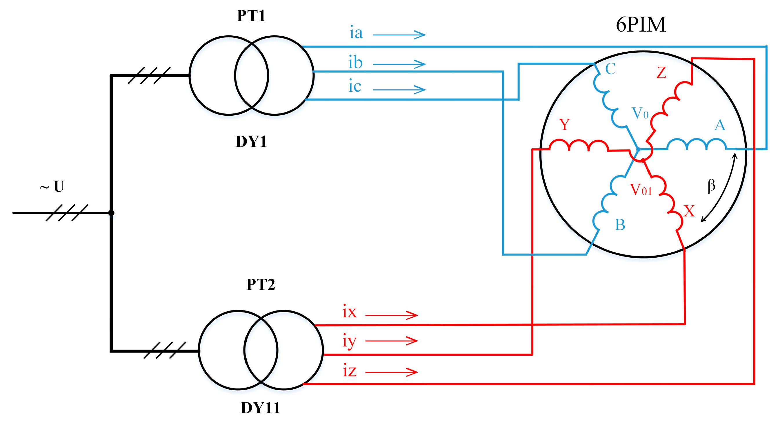
The block diagram of the symmetrical 6PIM is shown in Figure 1. Two three-phase windings with a spatial displacement of 60 electrical degrees (β = 60°) are supplied from power transformers PT1 and PT2. Three-phase voltages for the secondary windings of power transformers PT1 and PT2 are shifted by 60 electrical degrees. This is achieved by appropriately connecting the secondary windings of the power transformers.
The harmonic composition of the magnetomotive force caused by the influence of the spatial harmonics of machine windings is known. However, there is no sufficiently simple analytical description for the higher harmonics of the 6PIM electromagnetic torque caused by the interaction between the spatial harmonics of the machine windings and the time harmonics of the supply current. An analytical description is very important to identify ways to improve the electromechanical compatibility of the 6PIM with the load, particularly in eliminating the corresponding harmonics of the electromagnetic torque. Therefore, one of this paper’s tasks is to develop an analytical description of the appearance of the higher harmonics in the 6PIM electromagnetic torque caused by the interaction between the spatial harmonics of the machine windings and the time harmonics of the stator current.
Mathematical models based on the finite element method (FEM) are usually used for the analysis of the IM electromagnetic processes, taking into account spatial harmonics [28,29,30]. These models enable the analysis of the electromagnetic processes in steady-state modes of the IM and have a low-speed response. There are FEM models of the IM that cooperate with other simulation tools to take into account the space harmonics in the transient analysis [31]. The complexity of the mathematical description in field-oriented mathematical models and low calculation performance prevent the use of such models for the study of transient processes in multi-engine systems with semiconductor converters. In this regard, it is necessary to create fast-action mathematical models that would take into consideration the influence of spatial harmonics and enable the study of electromagnetic and electromechanical transient and steady-state processes in multi-engine complexes with semiconductor converters. This is the second task of the paper.
This paper presents an experimental study of the influence of the spatial harmonics of the winding function on the harmonic content of symmetrical 6PIM currents, the development of a 6PIM fast-action mathematical model that takes into account the influence of spatial harmonics, and an analysis of the influence of spatial harmonics on the harmonic content of the 6PIM electromagnetic torque.
The structure of this paper is as follows. An analytical description of the MMF and electromagnetic torque of the symmetrical 6PIM, taking into account space harmonics, is included in Section 2. Section 3 presents the mathematical model of the symmetrical 6PIM, taking into account space harmonics. The experimental test bench with the prototype of the symmetrical 6PIM is given in Section 4. Section 5 presents the experimental and simulation results of the symmetrical 6PIM. The conclusions are finally summarized in Section 6.
2. An Analytical Description of the 6PIM MMF and Electromagnetic Torque Taking into Account Spatial Harmonics
For an analytical description of the symmetrical 6PIM MMF, this section considers the sinusoidal supply of the 6PIM.
It is known that MMF in the air gap of a three-phase winding ABC contains, in addition to the first harmonic, higher harmonics, with the 5th, 7th, 11th and 13th harmonics having the most influence [13,14]. Taking this into account, the expressions for the MMF of phases A, B and C are written as follows:
where wA, wB, and wC—distribution function of winding coils w(η); wi—magnitude of the winding function’s harmonics (i = 1, 5, 7, 11, 13); η—spatial angle in electric degrees; Im1—magnitude of the phase current; ω = 2πf—angular frequency of the current; and ρ = 2π/3.
The MMF for the first three-phase winding ABC of the symmetrical 6PIM is determined:
Expression (2) is obtained taking into account the trigonometric transformations described in [24].
The MMF for the second three-phase winding XYZ of the symmetrical 6PIM is determined according to the following expression:
where —the spatial displacement between the first three-phase winding ABC and the second three-phase winding XYZ of the 6PIM in electrical degrees, and —the phase shift between the supply voltages of the 6PIM three-phase windings.
The resulting MMF in the air gap of the 6PIM is determined according to the following expression:
Taking into account that spatial displacement between the winding ABC and the winding XYZ of the symmetrical 6PIM is 60 electrical degrees () and the phase shift between the supply voltages of the symmetrical 6PIM is 60 electrical degrees (), Expression (4) is written as:
The magnitude of the MMF of the symmetrical 6PIM is determined by substitution according to the following expression:
The 5th and 7th spatial harmonics of the winding function lead to the appearance of the 6th time harmonic in the magnitude of the MMF and, accordingly, in the electromagnetic torque of the symmetrical 6PIM according to Expression (6). Similarly, the 11th and 13th spatial harmonics lead to the appearance of the 12th time harmonic in the magnitude of the MMF and in the electromagnetic torque of the symmetrical 6PIM.
Note that the obtained expressions correspond to the sinusoidal supply of 6PIM windings. In the case of the non-sinusoidal supply of 6PIM windings (using Voltage Source Inverters), the expression for the MMF will contain additional components caused by the influence of time harmonics on the winding supply. The interaction between the time harmonics of the winding supply and the spatial harmonics of the winding function is analytically analyzed in [24].
3. Mathematical Model Description of Symmetrical 6PIM Taking into Account Spatial Harmonics
The mathematical model of the symmetrical 6PIM was developed using the average voltages in integration step (AVIS) method. The main principles of the AVIS method are given in [32,33]. A feature of this method is its high calculation performance and numerical stability. It enables the creation of fast-response mathematical models, which can work in real-time mode with the interaction of physical objects (hardware-in-the-loop technology). Examples of such models for electrical drives with a three-phase IM are presented in [34,35], and power systems with wind turbines are discussed in [36]. Reference [37] presents mathematical models of electrotechnical systems with synchronous machines and technology for use in testing synchronous generator excitation systems. The AVIS method is used for creating models of power systems with nonlinear elements [38]. The specified examples testify to the adequacy of the chosen method and its efficiency for the modeling of electromagnetic and electromechanical processes in electrotechnical systems.
The universal equation for an electrical branch, which contains active resistance R and inductance L, is written according to the AVIS method [32]:
where i0—the branch current at the beginning of the integration step; m—the order of the polynomial that describes the current curve in the integration step (order of the method); —the average values in the integration step of the branch voltage; uR0—the voltage on the active resistance at the beginning of the integration step; ψ0, ψ1—the flux linkages at the beginning and at the end of the integration step; and Δt—the integration step.
Applying Equation (7) of the 2nd order AVIS for the stator and rotor windings of the IM, and taking into account that an increase in the flux linkages in the integration step is determined as , the vector equation is written as:
where —the vector of the average voltages in the integration step; —the instantaneous voltages; , —the vector of currents at the beginning and the end of the integration step; —the matrix of active resistances; , —the matrix of inductances at the beginning and the end of the integration step; and γR0, γR1—rotation angle at the beginning and the end of the step.
In order to determine the IM currents using the AVIS method of the 2nd order, time derivatives of the currents are used. The following equation can be written to find these derivatives:
Taking into account that the flux linkages in Expression (9) are functions of the currents and rotation angle, the time derivatives of flux linkages are determined as:
where p—the number of pole pairs; Ω—the rotation speed; and —the electromotive force of transformation and electromotive force of the rotation (components of the stator electromotive force).
According to Formulas (9) and (10), the expression for the derivatives of currents is:
The expression for the rotation angle and rotation speed is written as:
where TL—the load torque; Te—the electromagnetic torque of 6PIM; and J—the inertia.
The equation for electromagnetic torque is written as:
where —the stator and rotor winding currents in the αβ reference frame determined by the following expressions:
The matrix of inductances for the 6PIM is written as:
where the matrix of the self and mutual inductances for the stator (s1 and s2) and rotor windings (r) are:
the matrix of mutual inductances between the stator windings are:
and the matrix of mutual inductances between the stator and rotor windings are:
As was shown in Section 2, the presence of spatial harmonics leads to the appearance of time-harmonic components in the magnitude of the MMF in the air gap according to Expression (6). To take these harmonics to account, this paper proposes to define the magnetizing inductance of the 6PIM by introducing the time-harmonic components according to the following equation:
where L0—the magnitude of the zero harmonic; L6—the magnitude of the 6th harmonic; and L12—the magnitude of the 12th harmonic.
4. Experimental Test Bench
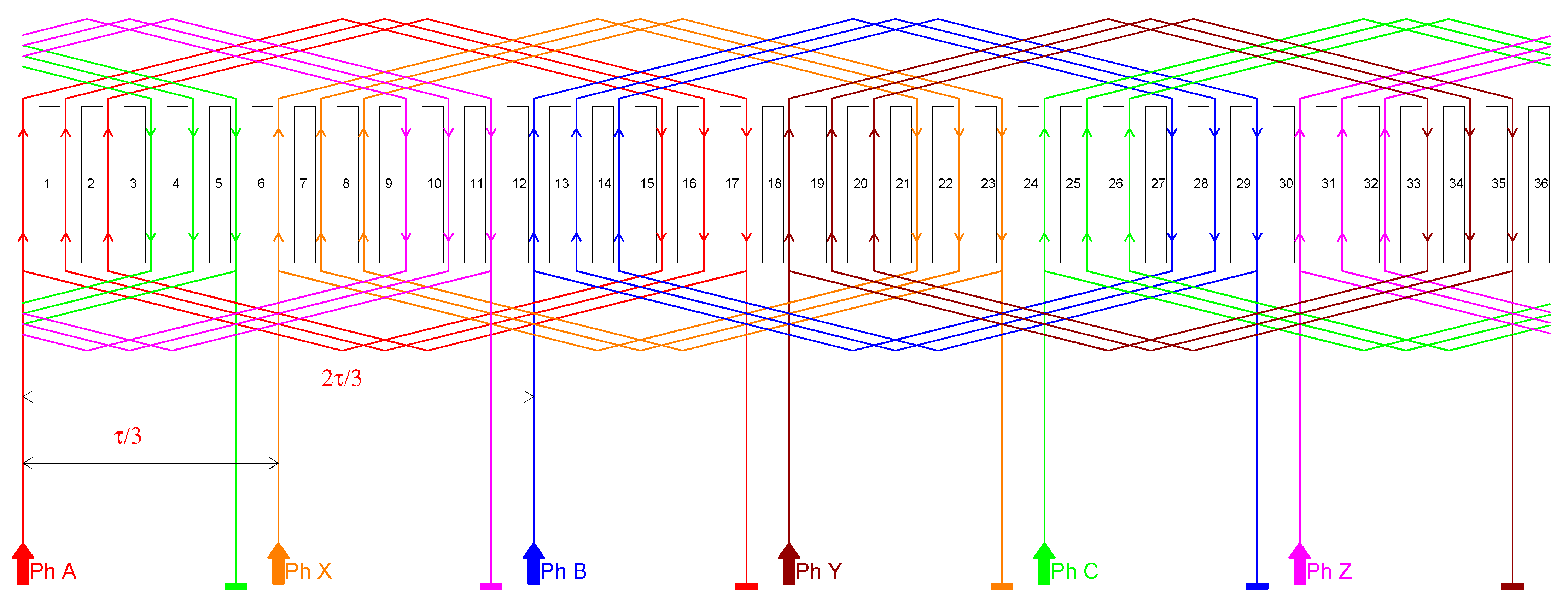
The prototype of the symmetrical 6PIM was created by the authors and has been used to analyze the spatial harmonic influence and verify the adequacy of the developed mathematical model. The scheme of the machine-winding distribution in the stator slots is shown in Figure 2. The parameters of 6PIM are: nominal power—1.5 kW, synchronous speed—3000 rpm.
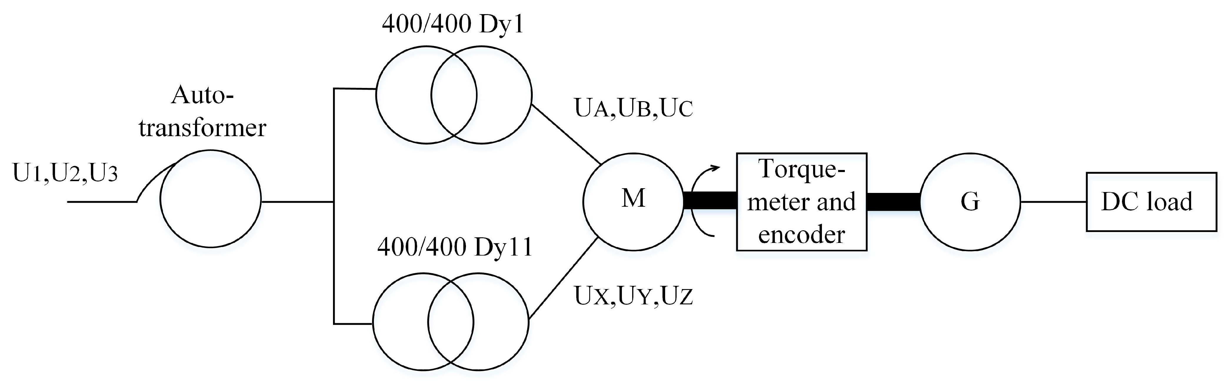
The experimental test bench is developed for the experimental study of the symmetrical 6PIM. The test bench consists of the prototype of the symmetrical 6PIM, power transformers PT1 and PT2, which supply the stator windings of the machine, a permanent magnet synchronous generator and an electrical DC load (Figure 3). The three-phase voltages of the PT1 and PT2 secondary windings are shifted by 60 electrical degrees.
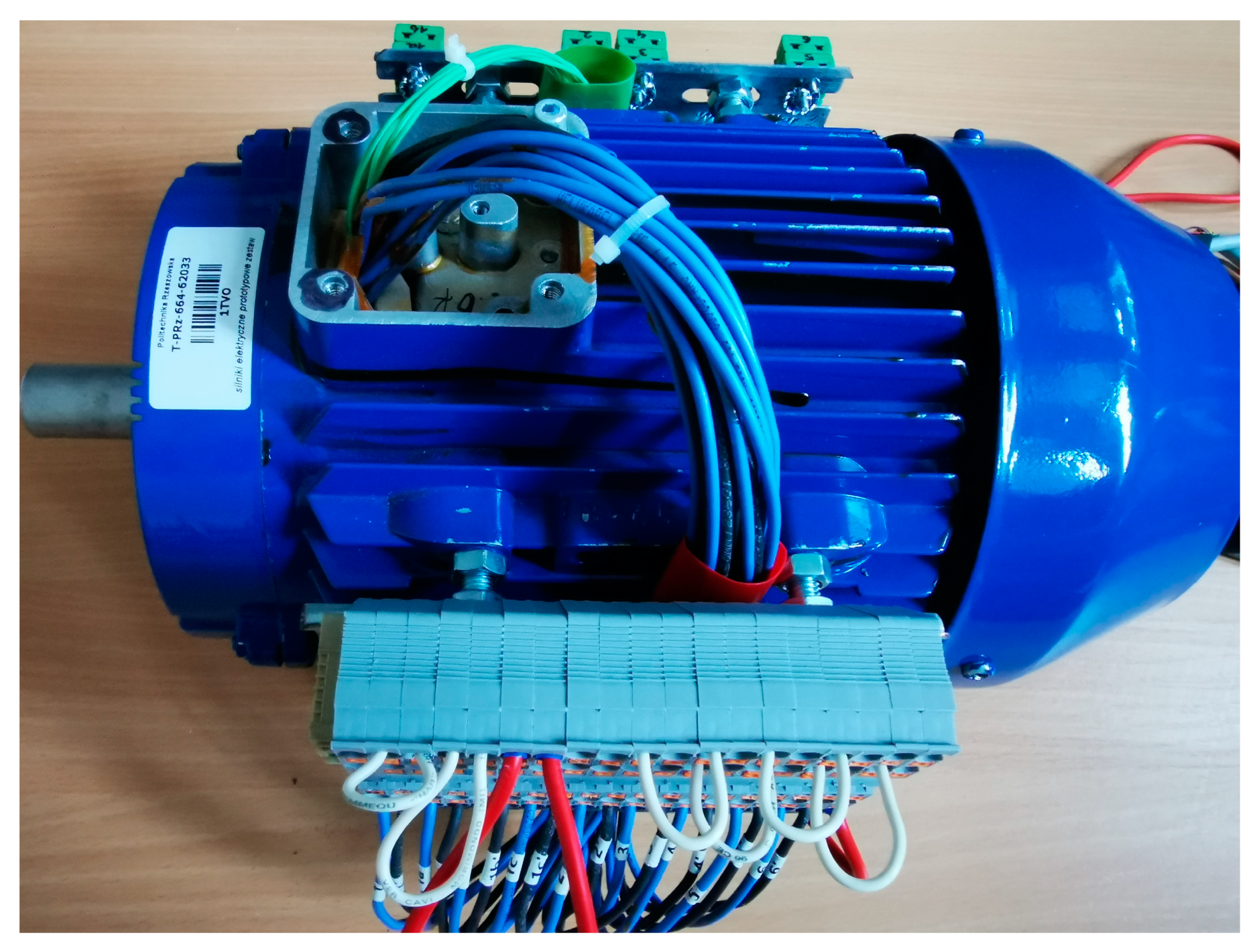
A prototype of the symmetrical 6PIM is shown in Figure 4.
5. Experimental and Simulation Results
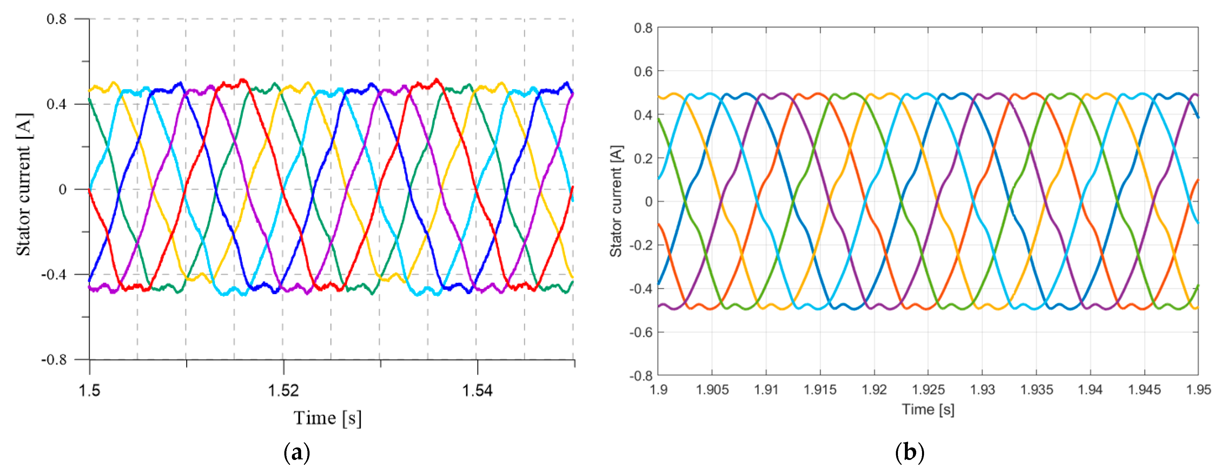
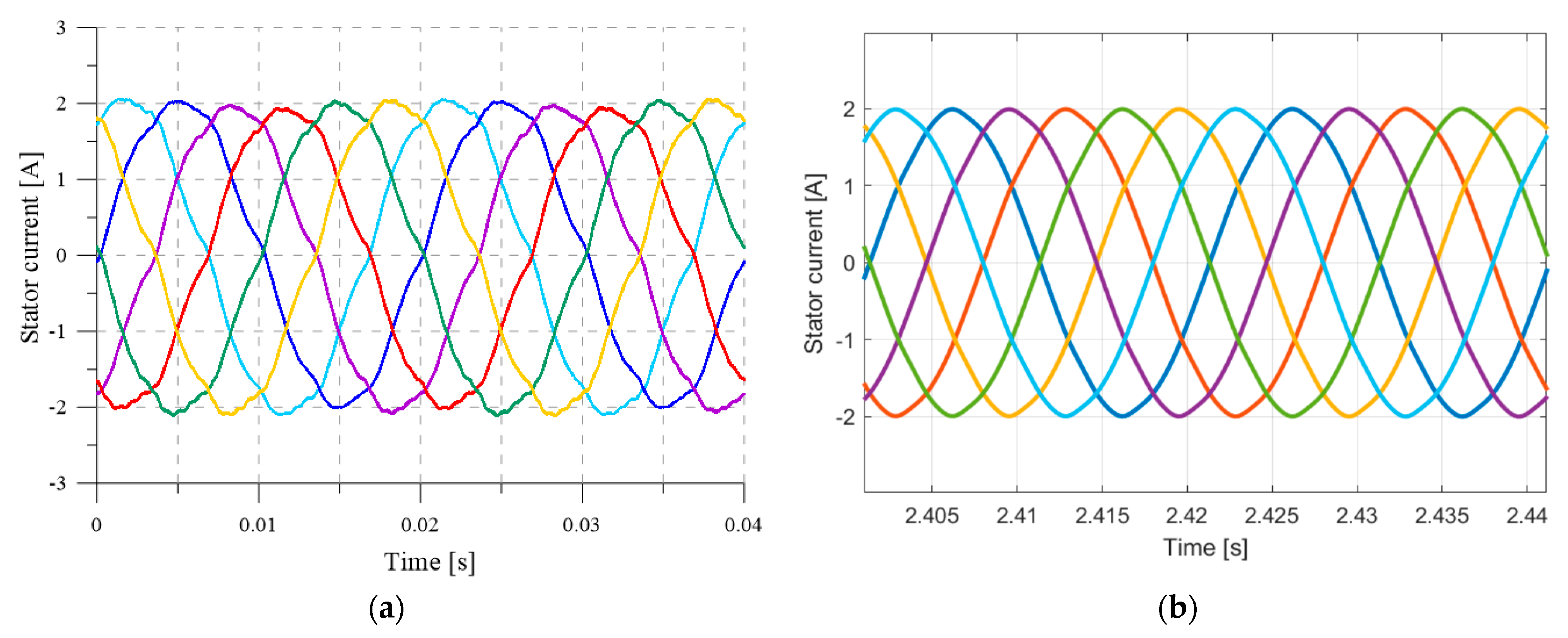
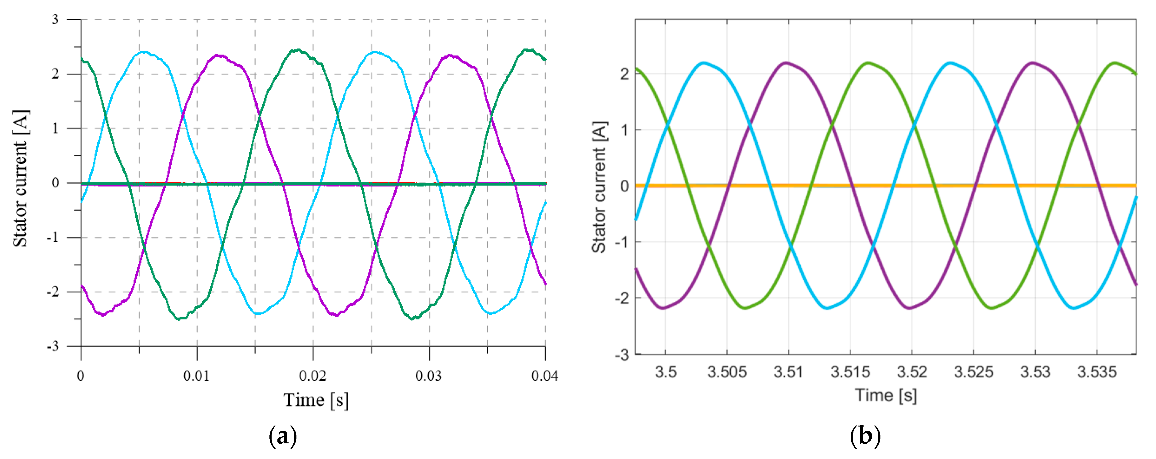
For checking the adequacy of the developed mathematical model of the symmetrical 6PIM, a comparison of the experimental results and the results of the mathematical modeling of the stator currents for normal and fault modes is conducted. The normal modes of the 6PIM are the 10% load (Figure 5) and the nominal load (Figure 6). The fault mode of the 6PIM is the three-phase ABC open fault (Figure 7). In this case, the winding supply voltage is purely sinusoidal. The 6PIM parameters used for the simulation are: PN = 1.5 kW, UN = 400 V, IN = 1.43 A, n = 2812 rpm, TN = 5.04 Nm, Lσ1 = 0.06 H, L′σ2 = 0.01 H, Lm = 1.3 H, R1 = 8.0 Ohm, R′2 = 4.0 Ohm, and J = 0.015 kg·m2.
The non-sinusoidal shape of the stator current of the 6PIM in all specified modes in the case of the sinusoidal winding supply voltage is explained by presence of the spatial harmonics winding distribution (magnetic flux in the air gap) and, accordingly, the non-sinusoidal stator electromotive force. In this case, the experimental and simulation results show that the high harmonic content of the stator current depends on the machine load (the load increase improves the current curve). The current curve is improved in the case of illumination of the influence for the one three-phase winding.
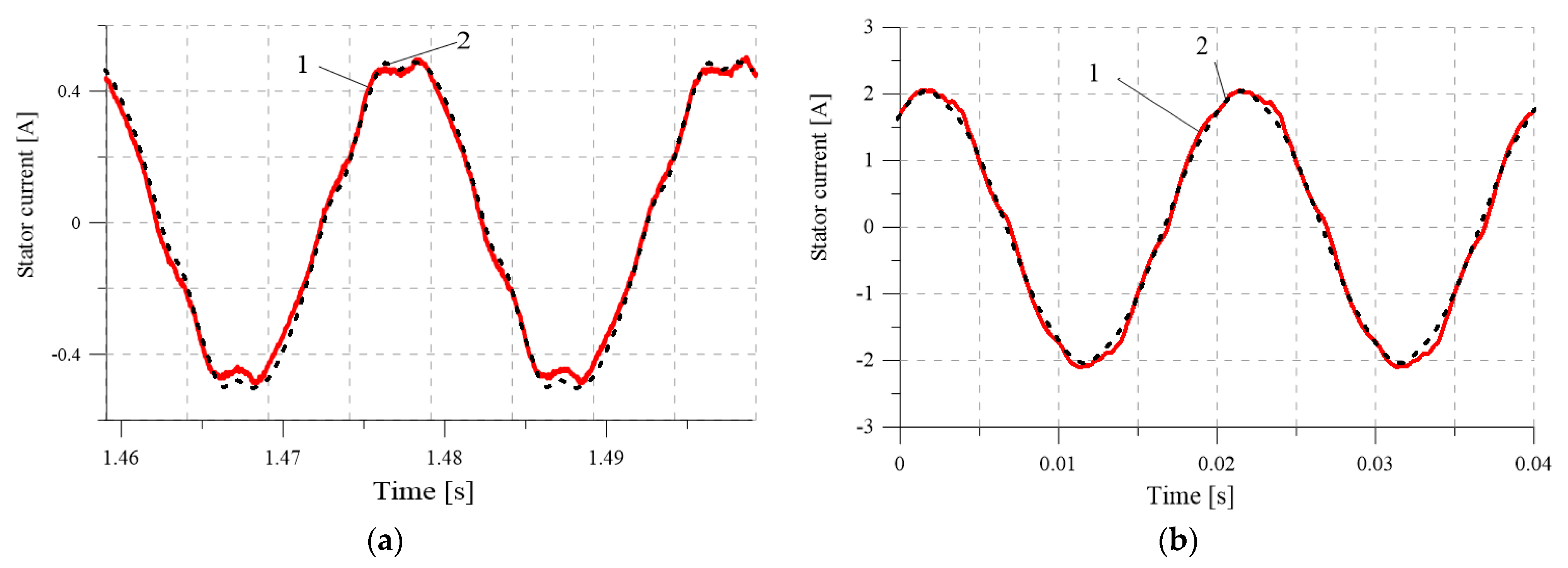
A detailed comparison of the experimental results and the results of the calculation using the developed mathematical model (Figure 8) shows the high coincidence of the instantaneous values of the currents, which confirms the adequacy of the model and the method used in terms of identifying the spatial harmonic influence on the electromagnetic processes. The maximum deviation of the calculated values from the experimental values occurs for the 10% machine load when the current distortions are at their maximum (Figure 8a). However, this deviation is not greater than 10%, which is an acceptable result.
The deviation of the simulation and experimental results for the nominal load is smaller, at 3% (Figure 8b). The maximum deviation of the simulation and experimental results for the single winding mode (three-phase ABC open fault) is 8%.
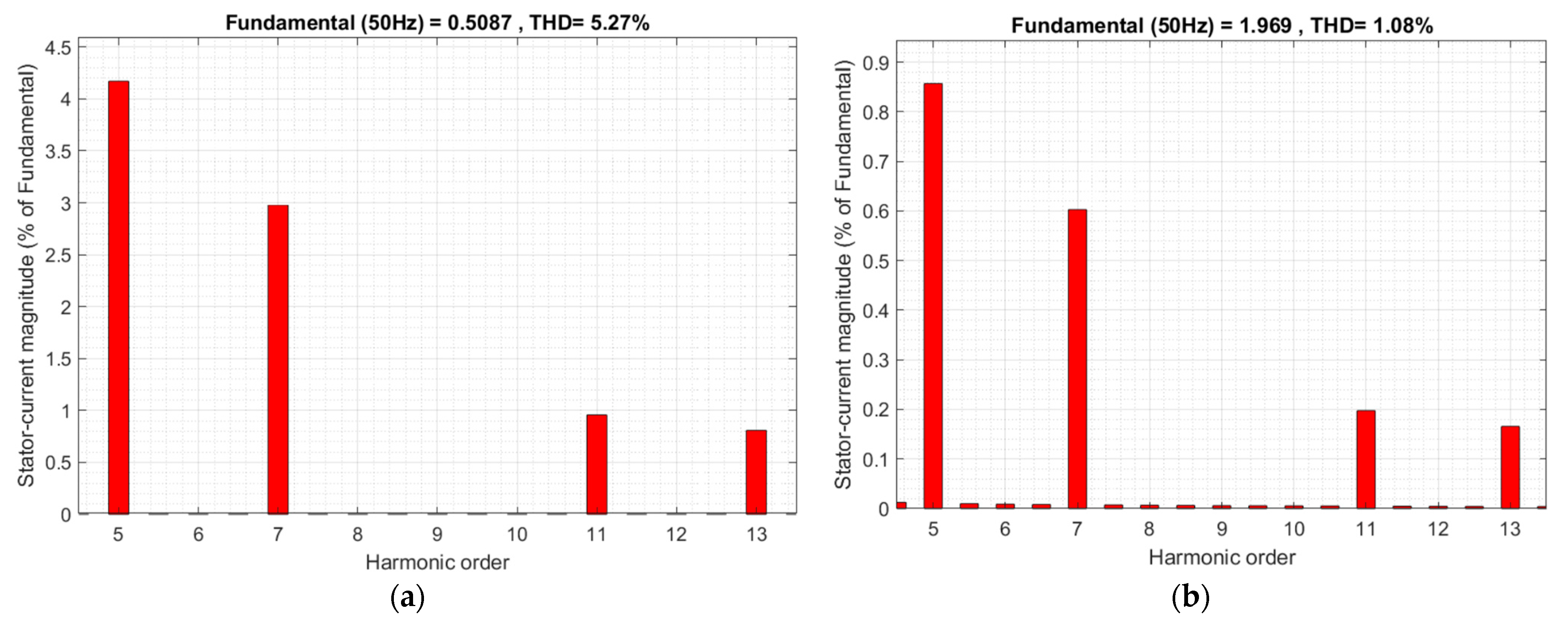
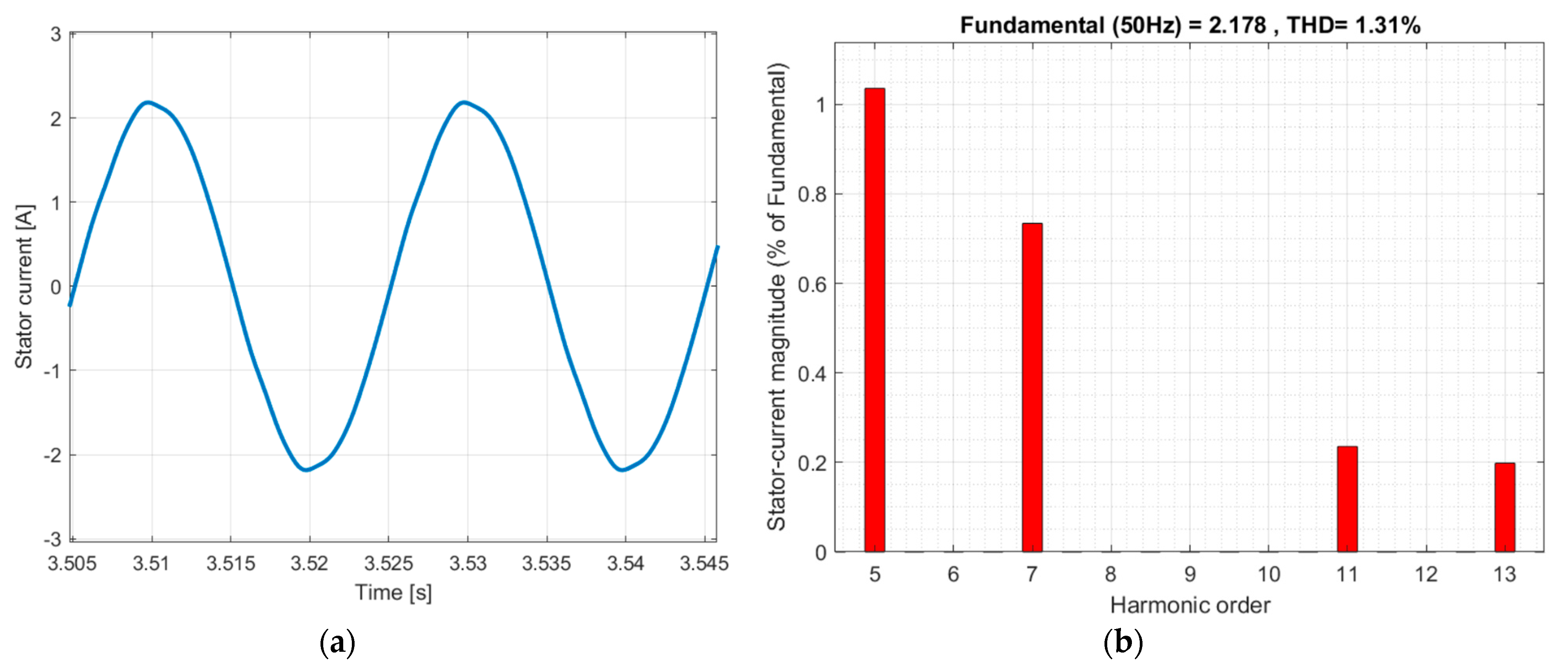
The harmonical analysis for the stator current of the symmetrical 6PIM shows the presence of the 5th, 7th and 11th, and 13th harmonics (higher harmonics can be neglected) in the stator current in all modes (Figure 9 and Figure 10), which are caused by the presence of spatial harmonics in the winding function. The high harmonic magnitude depends on the load. The magnitude of the 5th harmonic is 4.18 from the first (fundamental) harmonic for the 10% machine load and 0.86% from the first harmonic for the nominal load (Figure 9). The magnitude of the 5th harmonic is 1.18% from the first harmonic for the three-phase ABC open fault (Figure 10).
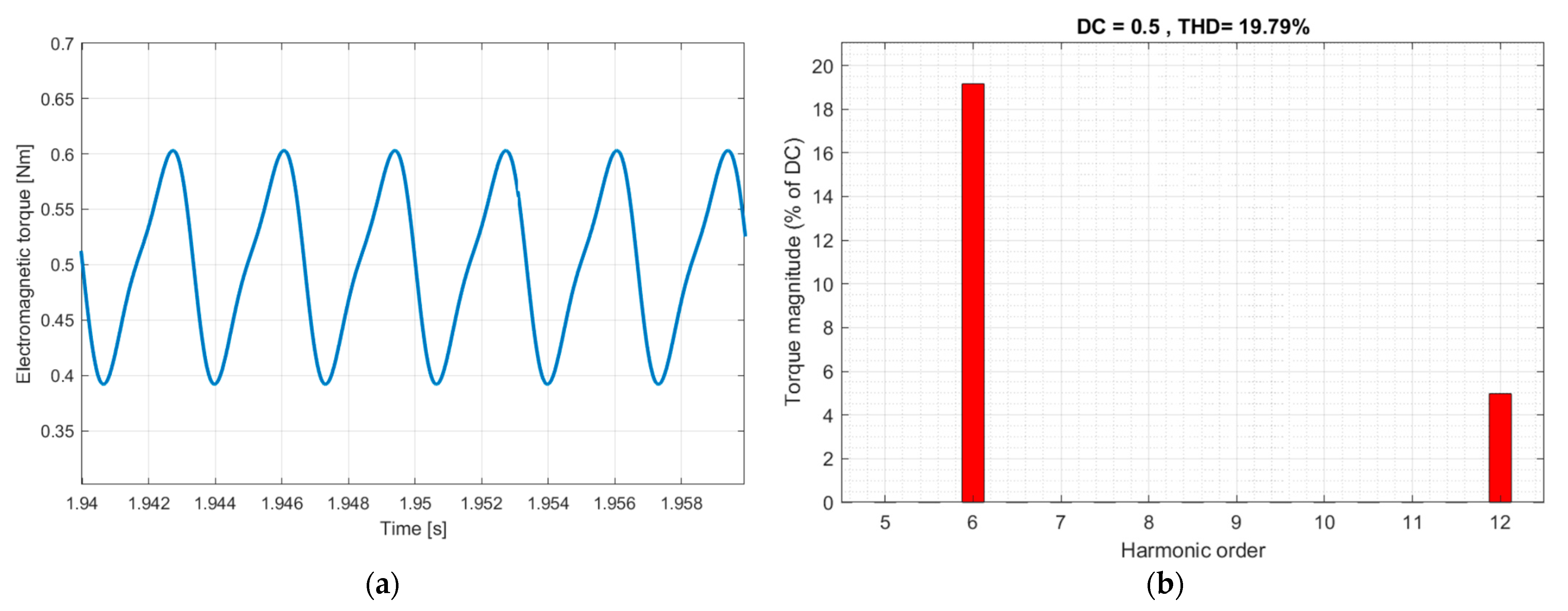
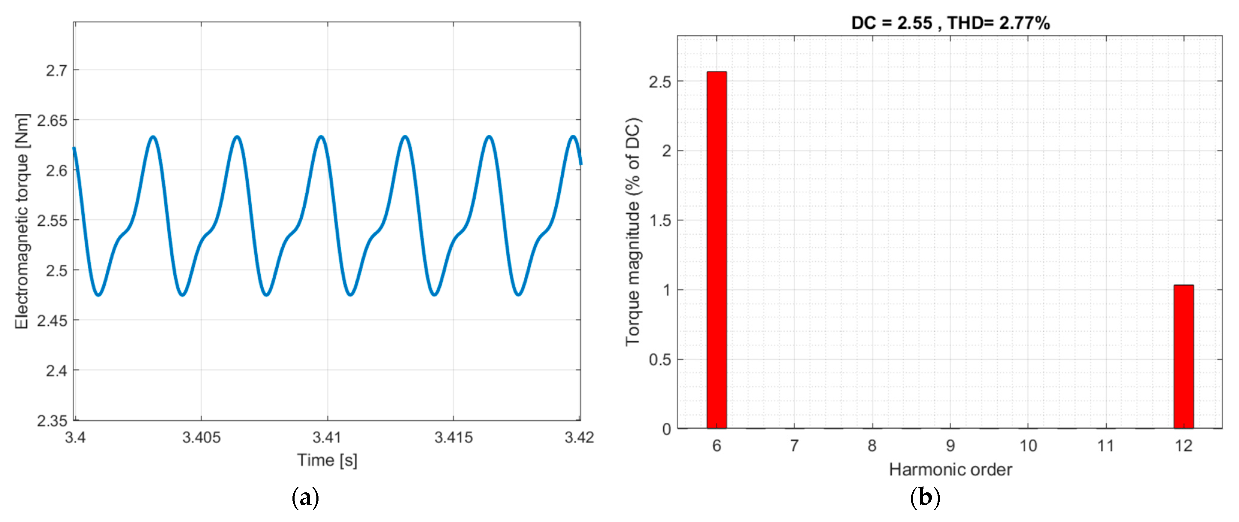
The non-sinusoidal stator current causes the ripples of the 6PIM electromagnetic torque. The curve and harmonic analyses of the 6PIM electromagnetic torque for the described modes are shown in Figure 11, Figure 12 and Figure 13.
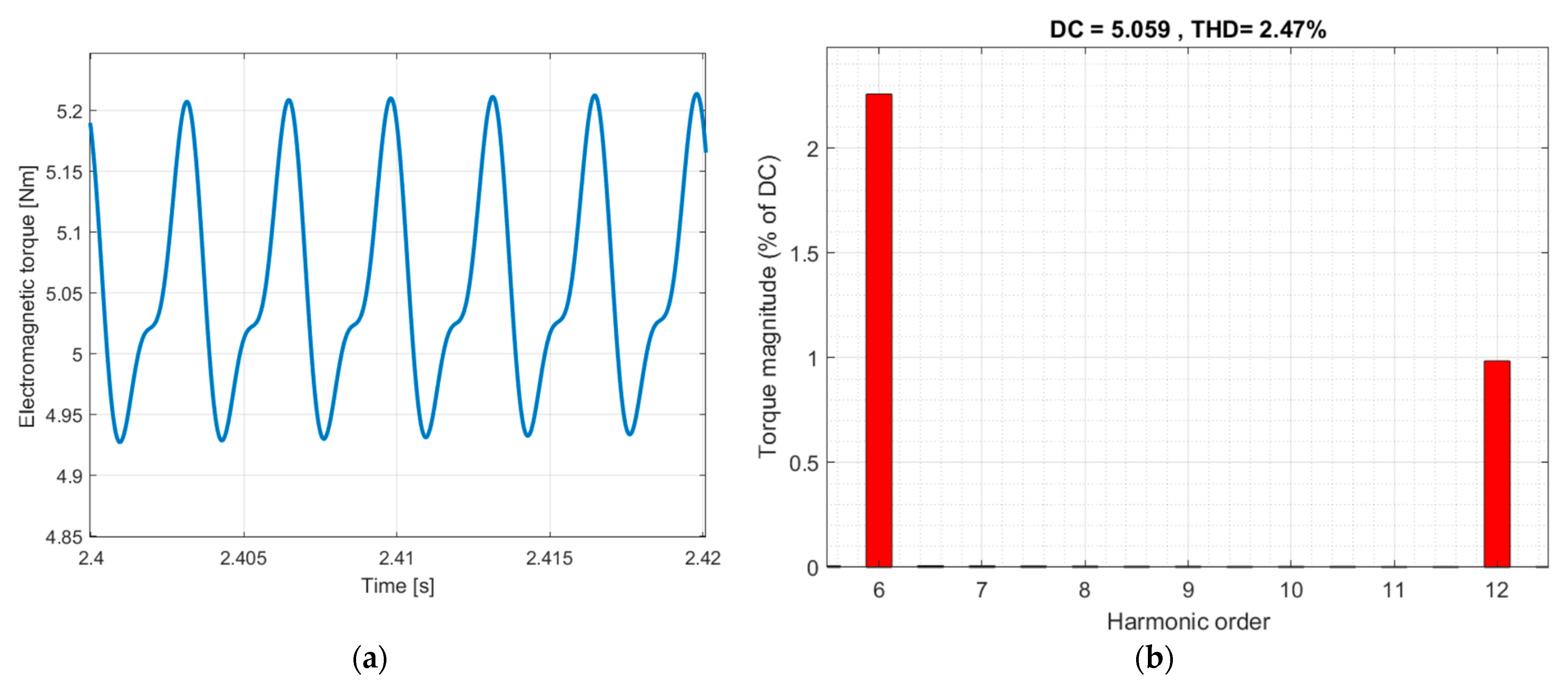
The harmonical analyses for the electromagnetic torque of the symmetrical 6PIM shows the presence of the 6th and 12th harmonics in the electromagnetic torque that agrees with the analytical description in Section 2. It is of note that the magnitude of the 6th harmonic is 19.16% from the zero harmonic for the 10% load mode (Figure 11) and 2.25% from the zero harmonic for the nominal load (Figure 12). The magnitude of the 6th harmonic is 2.51% from the zero harmonic for the three-phase ABC open fault and 50% load (Figure 13).
The harmonic spectrum of the stator current and the electromagnetic torque for the 10% load mode of the symmetrical 6PIM is shown in Table 1.
The comparison results of the total harmonic distortion (THD) in the stator current and the electromagnetic torque of the symmetrical 6PIM are shown in Table 2.
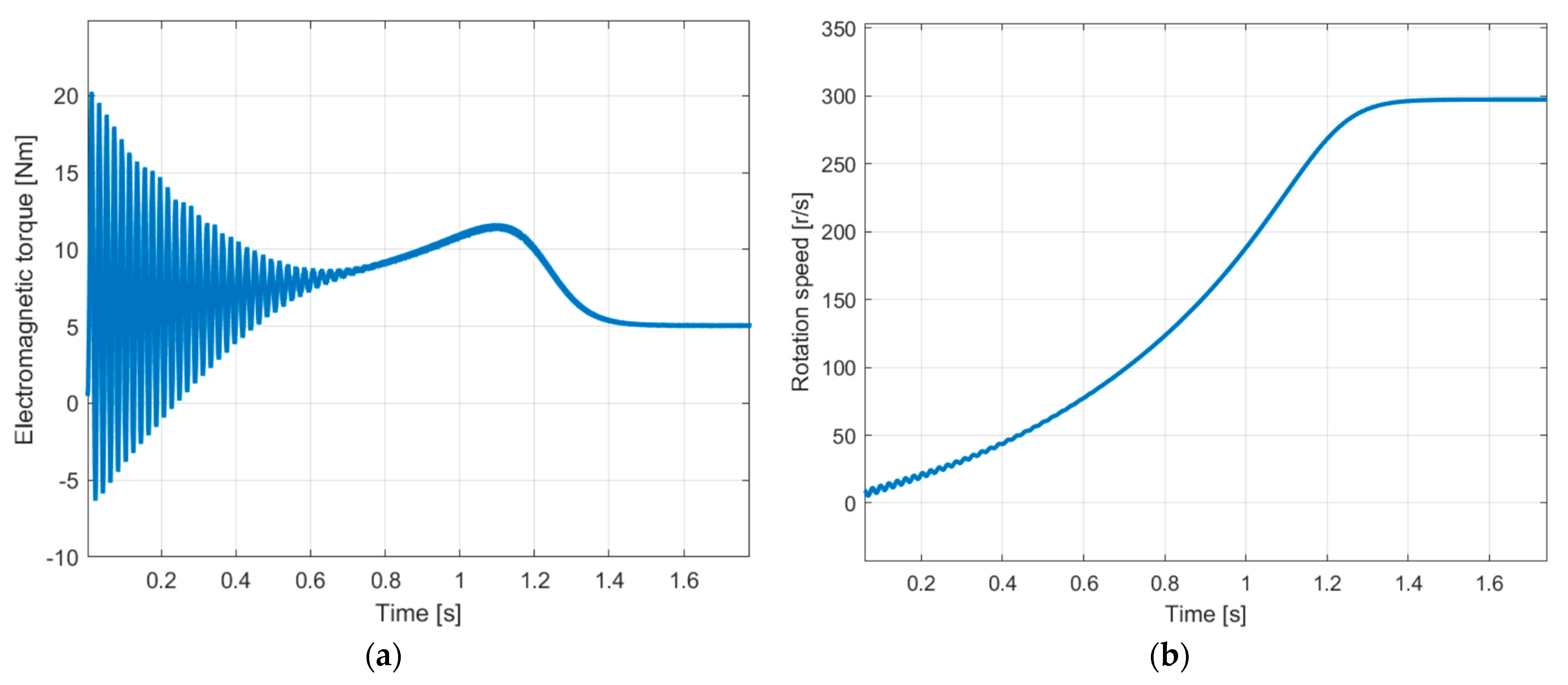
The simulation results for the start-up of the symmetrical 6PIM with nominal load are shown in Figure 14 and Figure 15. As in the case of the three-phase IM, there are significant pulsations of the electromagnetic torque; their magnitude is four times greater than the nominal value of the torque (Figure 14).
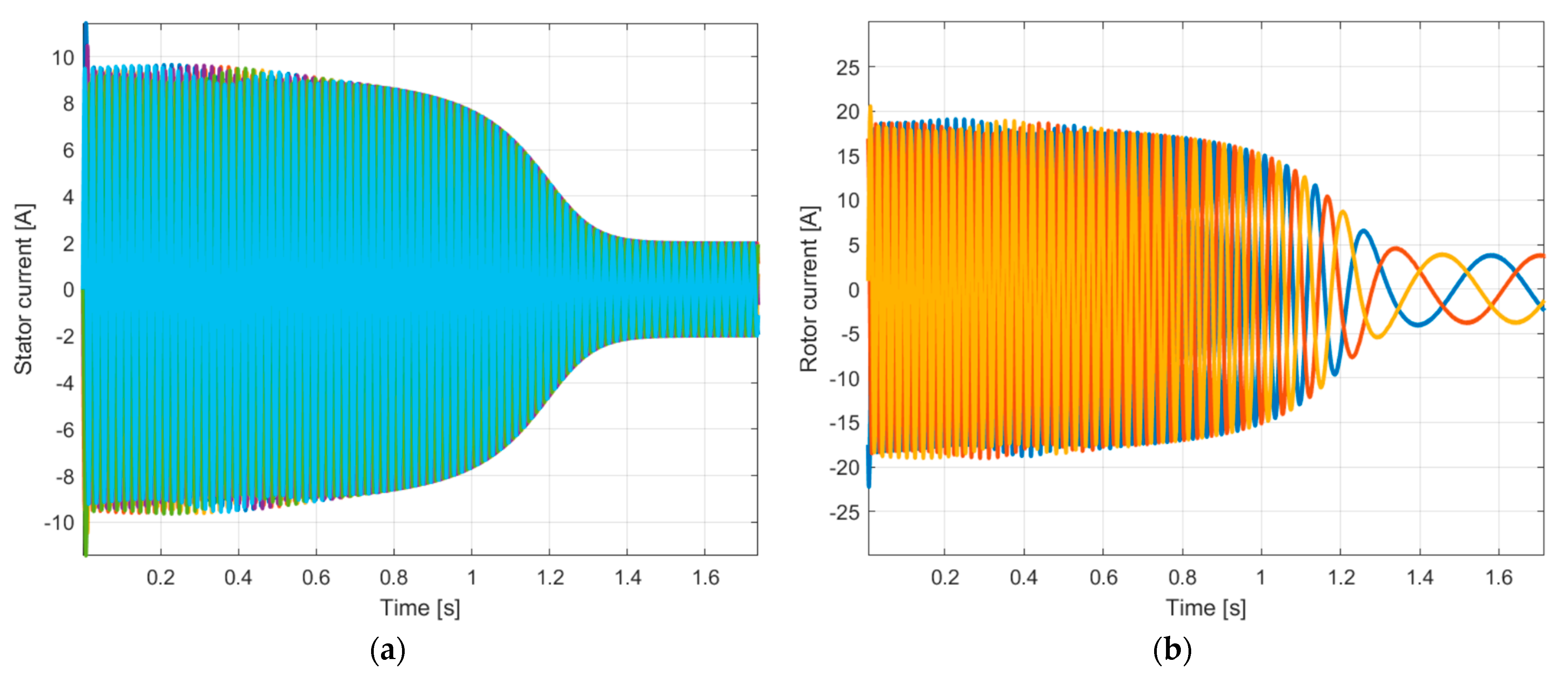
The stator and rotor currents of the 6PIM are shown in Figure 11.
6. Conclusions
The design of the IM does not allow the sinusoidal spatial distribution of the winding coil to be provided. This distribution is described as the winding function, which contains the first (fundamental) harmonic and the 5th, 7th, 11th and 13th harmonics. It is analytically shown that the interaction between the 5th and 7th spatial harmonics of the winding function of the symmetrical 6PIM and the 1st time harmonic of the winding supply leads to the appearance of the 6th time harmonic in the magnitude of the MMF and in the electromagnetic moment. Similarly, the interaction between the 11th and 13th spatial harmonics of the winding function and the 1st time harmonic of the winding supply leads to the appearance of the 12th time harmonic in the magnitude of the MMF and in the electromagnetic moment.
The experimental study of the prototype of the symmetrical 6PIM shows the distortion of the 6PIM currents in the case of the sinusoidal winding supply. This distortion is caused by the influence of spatial harmonics. The analysis of the harmonic content has proven the presence of the 5th, 7th, 11th and 13th harmonics in the stator current. The THD of the stator current is increased in the case of a reduction in the IM load. The THD of the stator current is reduced in the case of a three-phase ABC open fault.
The developed mathematical model for the electrical circuits of the symmetrical 6PIM using the AVIS method is characterized by a high calculation speed and takes into account the influence of the spatial harmonics by introducing the harmonic components into the model parameters. The adequacy of the mathematical model was proven by the comparison of the experimental and simulation results for the stator currents. The maximum deviation of the instantaneous values for the experimental and simulation results is 10%.
The greatest influence of the spatial harmonics on the IM electromagnetic torque is noticeable for small loads (for the investigated machine, THD = 19.79 by 10% load). This requires the use of methods for compensate for the influence of spatial harmonics in 6PIM due to the winding design and the winding supply scheme, which may be the subject of further research.
Author Contributions
Conceptualization, A.K. and M.K.; data curation, M.S.; formal analysis, A.K.; funding acquisition, M.K.; investigation, M.K. and M.S.; methodology, M.S.; project administration, M.K.; resources, M.K. and M.N.; software, M.S.; supervision, M.K.; validation, A.K. and M.K.; visualization, M.K.; writing—original draft, M.S.; writing—review and editing, A.K. All authors have read and agreed to the published version of the manuscript.
Funding
This research was financed in part by the statutory funds (UPB) of the Department of Electrodynamics and Electrical Machine Systems, Rzeszow University of Technology, and in part by the Ministry of Education and Science of the Republic of Poland within the “Regional Initiative of Excellence” program for the years 2019–2023. Project number 027/RID/2018/19; amount granted: PLN 11 999 900.
Data Availability Statement
Not applicable.
Conflicts of Interest
The authors declare no conflict of interest.
References
- Levi, E. Editorial—Special Issue on Multi-Phase Motor Drives. EPE J. 2004, 14, 4. [Google Scholar]
- Levi, E. Advances in converter control and innovative exploitation of additional degrees of freedom for multiphase machines. IEEE Trans. Ind. Electron. 2016, 63, 433–448. [Google Scholar] [CrossRef]
- Shchur, I.; Jancarczyk, D. Electromagnetic Torque Ripple in Multiple Three-Phase Brushless DC Motors for Electric Vehicles. Electronics 2021, 10, 3097. [Google Scholar] [CrossRef]
- Barrero, F.; Duran, M.J. Recent advances in the design, modeling and control of multiphase machines—Part 1. IEEE Trans. Ind. Electron. 2016, 63, 449–458. [Google Scholar] [CrossRef]
- Bojoi, R.; Farina, F.; Profumo, F.; Tenconi, A. Dual-Three Phase Induction Machine Drives Control—A Survey. IEEJ Trans. Ind. Appl. 2006, 126, 420–429. [Google Scholar] [CrossRef]
- Levi, E.; Barrero, F.; Duran, M.J. Multiphase machines and drives—Revisited. IEEE Trans. Ind. Electron. 2016, 63, 429–432. [Google Scholar] [CrossRef]
- Bojoi, R.; Caponet, M.C.; Grieco, G.; Lazzari, M.; Tenconi, A.; Profumo, F. Computation and measurements of the DC link current in six-phase voltage source PWM inverters for AC motor drives. In Proceedings of the Power Conversion Conference, Osaka, Japan, 2–5 April 2002; pp. 953–958. [Google Scholar] [CrossRef]
- Levi, E. Multiphase Electric Machines for Variable-Speed Applications. IEEE Trans. Ind. Electron. 2008, 55, 1893–1909. [Google Scholar] [CrossRef]
- Guzman, H.; Gonzalez, I.; Barrero, F.; Durán, M. Open-Phase Fault Operation on Multiphase Induction Motor Drives. Induction Motors—Applications, Control and Fault Diagnostics; IntechOpen: London, UK, 2015. [Google Scholar] [CrossRef]
- Munim, W.N.W.A.; Duran, M.J.; Che, H.S.; Bermúdez, M.; González-Prieto, I.; Rahim, N.A. A Unified Analysis of the Fault Tolerance Capability in Six-Phase Induction Motor Drives. IEEE Trans. Power Electron. 2017, 32, 7824–7836. [Google Scholar] [CrossRef]
- Benbouzid, M.E.H.; Diallo, D.; Zeraoulia, M. Advanced Fault-Tolerant Control of Induction-Motor Drive for EV/HEV Traction Applications: From Conventional to Modern and Intelligent Control Techniques. IEEE Trans. Veh. Tech. 2007, 56, 519–528. [Google Scholar] [CrossRef]
- Gan, C.; Li, X.; Yu, Z.; Ni, K.; Wang, S.; Qu, R. Modular Seven-Leg Switched Reluctance Motor Drive With Flexible Winding Configuration and Fault-Tolerant Capability. IEEE Trans. Transp. Electrif. 2022. [Google Scholar] [CrossRef]
- Xiaodong, L.; Yilmaz, L. Harmonic analysis for induction motors. In Proceedings of the IEEE CCECE/CCGEIJ, Ottawa, ON, Canada, 7–10 May 2006; pp. 172–176. [Google Scholar] [CrossRef]
- Park, S.-H.; Chin, J.-W.; Cha, K.-S.; Ryu, J.-Y.; Lim, M.-S. Investigation of AC Copper Loss Considering Effect of Field and Armature Excitation on IPMSM With Hairpin Winding. In Proceedings of the IEEE Transactions on Industrial Electronics, Singapore, 16–19 October 2023. [Google Scholar] [CrossRef]
- Kabir, M.A.; Jaffar, M.Z.M.; Wan, Z.; Husain, I. Design and experimental evaluation of a multilayer AC winding configuration for sinusoidal MMF with shorter end-turn length. In Proceedings of the 2017 IEEE Energy Conversion Congress and Exposition, Cincinnati, OH, USA, 1–5 October 2017; pp. 5834–5839. [Google Scholar] [CrossRef]
- Toliyat, H.A.; Lipo, T.A. Analysis of concentrated winding induction machines for adjustable speed drive applications-experimental results. IEEE Trans. Energy Convers. 1994, 9, 695–700. [Google Scholar] [CrossRef]
- El-Refaie, A.M.; Shah, M.R. Comparison of Induction Machine Performance with Distributed and Fractional-Slot Concentrated Windings. In Proceedings of the 2008 IEEE Industry Applications Society Annual Meeting, Edmonton, AL, Canada, 5–9 October 2008; pp. 1–8. [Google Scholar] [CrossRef]
- Neto, L.M.; Camacho, J.R.; Salerno, C.H.; Alvarenga, B.P. Analysis of a three-phase induction machine including time and space harmonic effects: The a, b, c reference frame. IEEE Trans. Energy Convers 1999, 14, 80–85. [Google Scholar] [CrossRef]
- Abdel-Khalik, A.S.; Masoud, M.I.; Ahmed, S.; Massoud, A.M. Effect of Current Harmonic Injection on Constant Rotor Volume Multiphase Induction Machine Stators: A Comparative Study. IEEE Trans. Ind. Appl. 2012, 48, 2002–2013. [Google Scholar] [CrossRef]
- Stincescu, R.B.; Viarouge, P.; Cros, J.; Kamwa, I. A general approach of space and time harmonics interactions in induction motors. In Proceedings of the IEEE International Electric Machines and Drives Conference, Hartford, CO, USA, 17–20 May 1999; pp. 366–368. [Google Scholar] [CrossRef]
- Sapena-Bano, A.; Martinez-Roman, J.; Puche-Panadero, R.; Pineda-Sanchez, M.; Perez-Cruz, J.; Riera-Guasp, M. Induction machine model with space harmonics for the diagnosis of rotor eccentricity, based on the convolution theorem. Int. J. Electr. Power Energy Syst. 2020, 117, 105625. [Google Scholar] [CrossRef]
- Sapena-Bano, A.; Martinez-Roman, J.; Puche-Panadero, R.; Pineda-Sanchez, M.; Perez-Cruz, J.; Riera-Guasp, M. Induction machine model with space harmonics for fault diagnosis based on the convolution theorem. Int. J. Electr. Power Energy Syst. 2018, 100, 463–481. [Google Scholar] [CrossRef]
- Lin, F.; Zuo, S.; Deng, W. Impact of rotor eccentricity on electromagnetic vibration and noise of permanent magnet synchronous motor. J. Vibroeng. 2018, 20, 923–935. [Google Scholar] [CrossRef]
- Kutsyk, A.; Korkosz, M.; Semeniuk, M.; Bogusz, P.; Lozynskyy, A.; Kozyra, J.; Łukasik, Z. Electromagnetic and Electromechanical Compatibility Improvement of a Multi-Winding Switch Control-Based Induction Motor—Theoretical Description and Mathematical Modeling. Energies 2022, 15, 8038. [Google Scholar] [CrossRef]
- Gonzalez-Prieto, A.; Gonzalez-Prieto, I.; Yepes, A.G.; Duran, M.J.; Doval-Gandoy, J. Symmetrical Six-Phase Induction Machines: A Solution for Multiphase Direct Control Strategies. In Proceedings of the 22nd IEEE International Conference on Industrial Technology, Shanghai, China, 22–25 August 2021; pp. 1362–1367. [Google Scholar] [CrossRef]
- Vukosavic, S.N.; Jones, M.; Levi, E.; Varga, J. Rotor fux oriented control of a symmetrical six-phase induction machine. Electr. Power Syst. Res. 2005, 75, 142–152. [Google Scholar] [CrossRef]
- Nabi, H.P.; Dadashi, P.; Shoulaie, A. A novel structure for vector control of a symmetrical six-phase induction machine with three current sensors. In Proceedings of the 10th International Conference on Environment and Electrical Engineering, Rome, Italy, 8–11 May 2011; pp. 1–5. [Google Scholar] [CrossRef]
- Mezani, S.; Laporte, B.; Takorabet, N. Complex finite element computation of induction motors with consideration of space harmonics. In Proceedings of the IEEE International Electric Machines and Drives Conference, Madison, MI, USA, 1–4 June 2003; Volume 1, pp. 264–268. [Google Scholar] [CrossRef]
- Oliveira, F.T.; Donsion, M.P. A finite element model of an induction motor considering rotor skew and harmonics. Renew. Energy Power Qual. J. 2017, 15, 119–122. [Google Scholar] [CrossRef]
- Carbonieri, M.; Bianchi, N.; Alberti, L. Induction motor mapping using rotor field-oriented analysis technique. In Proceedings of the 2019 IEEE Energy Conversion Congress and Exposition, Baltimore, ML, USA, 29 September–3 October 2019; pp. 2321–2328. [Google Scholar] [CrossRef]
- Leonardo, L.D.; Popescu, M.; Tursini, M.; Parasiliti, F.; Carbonieri, M. Transient Modeling of Induction Motors considering Space Harmonics. In Proceedings of the 2020 International Conference on Electrical Machines, Gothenburg, Sweden, 23–26 August 2020; pp. 2553–2559. [Google Scholar] [CrossRef]
- Plakhtyna, O.; Kutsyk, A.; Lozynskyy, A. Method of average voltages in integration step: Theory and application. Electr. Eng. 2020, 102, 2413–2422. [Google Scholar] [CrossRef]
- Plakhtyna, O.; Kutsyk, A.; Semeniuk, M. An analysis of fault modes in an electrical power-generation system on a real-time simulator with a real automatic excitation controller of a synchronous generator. Elektrotehniski Vestn. Electrotech. Rev. 2019, 86, 104–109. [Google Scholar]
- Kutsyk, A.; Lozynskyy, A.; Vantsevitch, V.; Plakhtyna, O.; Demkiv, L. A Real-Time Model of Locomotion Module DTC Drive for Hardware-In-The-Loop Implementation. Przegląd Elektrotechniczny 2021, 97, 60–65. [Google Scholar] [CrossRef]
- Kuznyetsov, O. Mathematical model of a three-phase induction machine in a natural abc reference frame utilizing the method of numerical integration of average voltages at the integration step and its application to the analysis of electromechanical systems. Math. Probl. Eng. 2019, 2019, 4581769. [Google Scholar] [CrossRef]
- Kłosowski, Z. The analysis of the possible use of wind turbines for voltage stabilization in the power node of MV line with the use of a real-time simulator. Przegląd Elektrotechniczny 2015, 1, 20–27. (In Polish) [Google Scholar]
- Kutsyk, A.; Semeniuk, M.; Korkosz, M.; Podskarbi, G. Diagnosis of the Static Excitation Systems of Synchronous Generators with the Use of Hardware-In-the-Loop Technologies. Energies 2021, 14, 6937. [Google Scholar] [CrossRef]
- Lozynskyy, A.; Kozyra, J.; Łukasik, Z.; Ku´smi´nska-Fijałkowska, A.; Kutsyk, A.; Paranchuk, Y.; Kasha, L. A Mathematical Model of Electrical Arc Furnaces for Analysis of Electrical Mode Parameters and Synthesis of Controlling Influences. Energies 2022, 15, 1623. [Google Scholar] [CrossRef]
Figure 1.
Symmetrical six-phase induction machine.

Figure 2.
Winding scheme of the symmetrical 6PIM.

Figure 3.
Block diagram of the experimental test bench with symmetrical 6PIM.

Figure 4.
Prototype of the symmetrical 6PIM.

Figure 5.
Stator current of the 6PIM for the 10% load: (a) the experiment, (b) the simulation (the phase currents of the windings are marked with different colors here and further).
Figure 5.
Stator current of the 6PIM for the 10% load: (a) the experiment, (b) the simulation (the phase currents of the windings are marked with different colors here and further).

Figure 6.
Stator currents of the 6PIM in the steady-state mode for the nominal load: (a) the experiment, (b) the simulation.
Figure 6.
Stator currents of the 6PIM in the steady-state mode for the nominal load: (a) the experiment, (b) the simulation.

Figure 7.
Stator currents of the 6PIM in the steady-state mode for the 50% load and three-phase ABC open fault: (a) the experiment, (b) the simulation.
Figure 7.
Stator currents of the 6PIM in the steady-state mode for the 50% load and three-phase ABC open fault: (a) the experiment, (b) the simulation.

Figure 8.
Stator currents of 6PIM in the steady-state mode: (a)—for the 20% load, (b)—for the nominal load, 1—the experimental result (red solid line), 2—the simulation result (black dashed line).
Figure 8.
Stator currents of 6PIM in the steady-state mode: (a)—for the 20% load, (b)—for the nominal load, 1—the experimental result (red solid line), 2—the simulation result (black dashed line).

Figure 9.
High harmonic spectrum of the 6PIM stator current (a)—for the 10% load, (b)—for the nominal load.
Figure 9.
High harmonic spectrum of the 6PIM stator current (a)—for the 10% load, (b)—for the nominal load.

Figure 10.
(a) Stator current of the 6PIM for the 50% load and the three-phase ABC open fault and (b) the high harmonic spectrum.
Figure 10.
(a) Stator current of the 6PIM for the 50% load and the three-phase ABC open fault and (b) the high harmonic spectrum.

Figure 11.
(a) Electromagnetic torque of the 6PIM for the 10% load and (b) the high harmonic spectrum of the electromagnetic torque.
Figure 11.
(a) Electromagnetic torque of the 6PIM for the 10% load and (b) the high harmonic spectrum of the electromagnetic torque.

Figure 12.
(a) Electromagnetic torque of the 6PIM in the steady-state mode for the nominal load and (b) the high harmonic spectrum of the electromagnetic torque.
Figure 12.
(a) Electromagnetic torque of the 6PIM in the steady-state mode for the nominal load and (b) the high harmonic spectrum of the electromagnetic torque.

Figure 13.
(a) Electromagnetic torque of the 6PIM in the steady-state mode for the 50% load and the three-phase ABC open fault and (b) the high harmonic spectrum of the electromagnetic torque.
Figure 13.
(a) Electromagnetic torque of the 6PIM in the steady-state mode for the 50% load and the three-phase ABC open fault and (b) the high harmonic spectrum of the electromagnetic torque.

Figure 14.
(a) Electromagnetic torque and (b) rotation speed of the 6PIM in the transient mode for the nominal load.
Figure 14.
(a) Electromagnetic torque and (b) rotation speed of the 6PIM in the transient mode for the nominal load.

Figure 15.
(a) Stator currents and (b) rotor currents of the 6PIM in the transient mode for the nominal load.
Figure 15.
(a) Stator currents and (b) rotor currents of the 6PIM in the transient mode for the nominal load.


Table 1.
Harmonic spectrum of the stator current and the electromagnetic torque for 10% load mode of the 6PIM (missing harmonics are not shown in the table).
Table 1.
Harmonic spectrum of the stator current and the electromagnetic torque for 10% load mode of the 6PIM (missing harmonics are not shown in the table).
| Harmonic Order | Stator Current Harmonic Magnitude, % | Electromagnetic Torque Harmonic Magnitude, % |
|---|---|---|
| 0 | 0 | 100 |
| 1 | 100 | 0 |
| 5 | 4.17 | 0 |
| 6 | 0 | 19.18 |
| 7 | 2.98 | 0 |
| 11 | 0.96 | 0 |
| 12 | 0 | 4.92 |
| 13 | 0.81 | 0 |
| 17 | 0.02 | 0 |
| 18 | 0 | 0.12 |
Table 2.
THD of the 6PIM stator current and electromagnetic torque.
| Mode of 6PIM | THD,% | |
|---|---|---|
| Stator Current | Electromagnetic Toque | |
| 10% load mode | 5.27 | 19.79 |
| nominal load | 1.08 | 2.47 |
| 50% load and three open-phase ABC fault | 1.13 | 2.77 |
Disclaimer/Publisher’s Note: The statements, opinions and data contained in all publications are solely those of the individual author(s) and contributor(s) and not of MDPI and/or the editor(s). MDPI and/or the editor(s) disclaim responsibility for any injury to people or property resulting from any ideas, methods, instructions or products referred to in the content. |
© 2023 by the authors. Licensee MDPI, Basel, Switzerland. This article is an open access article distributed under the terms and conditions of the Creative Commons Attribution (CC BY) license (https://creativecommons.org/licenses/by/4.0/).
Share and Cite
MDPI and ACS Style
Kutsyk, A.; Korkosz, M.; Semeniuk, M.; Nowak, M. An Influence of Spatial Harmonics on an Electromagnetic Torque of a Symmetrical Six-Phase Induction Machine. Energies 2023, 16, 3813. https://doi.org/10.3390/en16093813
AMA Style
Kutsyk A, Korkosz M, Semeniuk M, Nowak M. An Influence of Spatial Harmonics on an Electromagnetic Torque of a Symmetrical Six-Phase Induction Machine. Energies. 2023; 16(9):3813. https://doi.org/10.3390/en16093813
Chicago/Turabian StyleKutsyk, Andriy, Mariusz Korkosz, Mykola Semeniuk, and Marek Nowak. 2023. "An Influence of Spatial Harmonics on an Electromagnetic Torque of a Symmetrical Six-Phase Induction Machine" Energies 16, no. 9: 3813. https://doi.org/10.3390/en16093813
Note that from the first issue of 2016, this journal uses article numbers instead of page numbers. See further details here.