
Physics-Based Prediction for the Consumption and Emissions of Passenger Vehicles and Light Trucks up to 2050

Chair of Measurement and Control Systems, Center of Energy Technology (ZET), Universität Bayreuth, Universitätsstr. 30, 95447 Bayreuth, Germany
*
Author to whom correspondence should be addressed.
Energies 2023, 16(8), 3591; https://doi.org/10.3390/en16083591
Submission received: 13 March 2023
/
Revised: 5 April 2023
/
Accepted: 16 April 2023
/
Published: 21 April 2023
Abstract
:The increasing market share of electric vehicles and the politically intended phase-out of the internal combustion engine require reliable and realistic predictions for future consumption and greenhouse gas emissions as a function of technological solutions. This also includes the consumption- and emission-intensive transport of goods. We consider both passenger vehicles and commercial vehicle traffic in our study and have investigated whether there are drive alternatives to the battery electric vehicle that enable uninterrupted trips with a long range, especially for regional delivery services and internationally active freight forwarders. To this end, we have analysed three system architectures and their expected technological progress until 2050: battery electric vehicles (BEV), fuel cell electric vehicles (FCEV), and internal combustion engine vehicles (ICEV) running on compressed natural gas (CNG). The latter case serves as a best-practice reference from a combustion technology perspective. The analysis is based on a validated and proven physical model and predicts that the BEV2050 will consume 3.5 times less energy and emit 15 times fewer greenhouse gases than the ICEV-CNG2020, whereas the FCEV2050 will consume 2.5 times less energy and emit 6.5 times fewer greenhouse gases than the ICEV-CNG2020 on the road (hilly terrain, transition season, and WLTP triple-mixed drive cycle). The advantages of the BEV result from the shorter drive train with lower total losses. Our results thus confirm the expected role of the BEV as the dominant drive technology in the future, and light vehicles with low-to-medium-range requirements will especially benefit from it. On the other hand, since the greenhouse gas emissions of the FCEV2050 are lower by a factor of 6.5 than those of the ICEV-CNG2020, it is reasonable to conclude that the FCEV can play a significant role in transport until 2050 when long distances have to be covered. Our model-based approach also allows us to determine the energy fractions of the acting physical forces and thus calculate the consumption shares: electric drive recuperation increases BEV and FCEV range by about 15% in 2020 and will increase it by about 20% in 2050, depending on drive technology and vehicle type. Air and rolling resistance contribute 20% each to the total consumption. The consumption of the accessories of modern vehicles with a share of about 10% of the total consumption cannot be neglected.
1. Introduction
Electric drive technology for vehicles is more than 100 years old. It lost the competition with gasoline-powered internal combustion engines back then because the ranges that could be realized with the very limited battery capacities of the time were not sufficient. The question of greenhouse gas (GHG) emissions would have been better asked back then, too—but it was not. This has changed drastically in the meantime, with several governments in Europe, North America, and Asia, as well as major vehicle manufacturers such as VW, Renault and Volvo, having decided to ban or stop the sale of vehicles with fossil combustion engines before 2040 [1,2,3,4]. The sector of traffic and transport is thus supposed to make its contribution to the reduction in GHG emissions, which has not happened so far [5,6,7,8].
For the user of automobiles, be it private or business, this raises several questions that have not been fully clarified: Is the range of today’s batteries sufficient for long-distance travel? What GHG emissions does a future vehicle produce per distance travelled? What drive options are available to the freight forwarding company serving its international customers to be able to comply with the strict requirements of the legislator in the long term?
Such questions are all the more justified as some of the claimed impressive advantages of modern drives do not stand up to scrutiny. For example, the German government considers battery electric vehicles (BEVs) to be completely emission-free and therefore gives them preferential treatment under tax law [9,10]. Of course, this definition is based on political intentions rather than scientific objectivity. There is no doubt that the manufacturing process of modern automobiles with new drive technologies involves a considerable input of raw materials and energy, which in some cases goes well beyond what would be used to produce conventional automobiles. Just think of the raw-material-intensive lithium-ion batteries or the rare-earth magnets used in electric motors [10,11,12].
Even in operation, there is no question of real CO2 neutrality because the electricity required for operation is not generated completely by regenerative energy in any current economy [13]. The same applies to hydrogen needed for fuel cells [14,15]. Manufacturers’ data on consumption and emissions of the new drive technologies do not reliably answer critical consumer questions. Past and present experience has shown repeatedly that real-world consumption significantly exceeds manufacturer’s figures. There is evidence that this is also true for electrically powered vehicles [16,17,18]. This is because very favourable conditions are generally applied on the test benches of the manufacturers: no height profiles, warm summer temperatures, accessories turned off, etc.
In this respect, the new drive technologies represent a broad field of application for scientific reappraisal. Only the broad application of scientific methods can create transparency about the current performance and usability of electrically driven vehicles and lay the foundation for future development.
Despite the extensive global research efforts, the scientific database is incomplete and obscured by economically or politically motivated statements that do not stand up to objective scrutiny. In order to rule out erroneous developments in vehicle technology, the expected technological trends to 2050 have to be derived more systematically from available data. The GHG emissions of the various drive technologies are directly related to the generation of the associated energy fuel—in our case electricity and hydrogen. Both the paths of production and their efficiencies are subject to dynamic development and require continuous evaluation.
The emission factor for electricity generation varies strongly from country to country [19]. However, even within a country such as Germany, on which we focus, the emission factors predicted today for the year 2050 diverge by a factor of 12 [20,21]. Even for a medium-term horizon to 2030, there are differences of 100% in predicted numbers. It is evident that there is an urgent need to reduce these large differences based on objective data that are based on scientific reasoning (see Section 3.4.1).
There is also a lack of scientific data regarding the extent to which the BEV will be suitable for use in commercial vehicles over long distances. Hopes for this are being fuelled by the assumption of major advances in the power density of batteries and the available charging power along the main transport routes. To gain well-founded insight into this core issue of future mobility, on the one hand, the expected battery technology development needs to be included more consistently in consumption calculations (see Section 3.3.1), and on the other hand, it must be examined without prejudice, whether the goals cannot be achieved more realistically with alternative technologies. This can only be accomplished by an objective system comparison of BEVs and FCEVs both for passenger and commercial vehicles to 2050, a comparison that cannot be found in the open literature as of now.
This study aims to investigate the relative merits of future drive technologies in traffic and transport and the expected progress until 2050. We determine the specific consumption and GHG emissions under real-world conditions by simulations that allow sound, objective, and practically relevant predictions for mobility groups as opposed to individual vehicles. The simulations are based on a physical model involving the main components of a vehicle powertrain, all of the forces acting on the vehicle, and real-world conditions. The model has been described in [16]. It has been demonstrated that the simulations based on this model agree very well with other scientific investigations, with practical consumption tests of recognized testing institutes/organizations [22] and with our own road tests [16] (see Appendix A). Such comparison with available experimental data is ample reason to consider the model as validated. We now apply the model to investigate future vehicle behaviour, which is impossible through experiments because the vehicles have not been built yet.
In the present continuation of [16], we explore two electric powertrain architectures: (1) all-electric vehicles (BEVs) and (2) fuel cell electric vehicles (FCEVs), with a hydrogen fuel cell and a small battery as combined energy storage. In both cases, lithium iron phosphate batteries are assumed, as this battery technology is the most promising due to its high cycle stability and short-circuit resistance, coupled with a relatively high power density. Compared to the battery, the fuel cell, with its hydrogen tank, has a much higher power density (Figure 1). This would allow significantly longer ranges for electric vehicles, especially for heavy trucks. However, the electrical energy for the FCEV must additionally be converted into hydrogen in an electrolyser and later back into electricity in the vehicle by the fuel cell. These conversions involve losses. The investigation of such trade-offs is the essential objective of our present work. To this end, we will expand known data [14,15,23] with additional insights into the specific consumption and the GHG emissions of the electric drive variants under real-world conditions.
In order to be able to make a better comparison with the state-of-the-art technology of internal combustion engines (ICEs), we have examined the combustion drive with compressed natural gas (CNG) as a third drive variant. This combustion engine is economical in consumption, with relatively low GHG emissions and should not be ruled out in long-distance operation, all the more so as the energy density of CNG is high when compared to batteries (Figure 1).
All three drive technologies (BEV, FCEV, and ICEV–CNG) have been studied according to their current performance and according to their likely further development until 2050. The results are intended to help assess the feasibility of the political objectives at the milestones of the Kyoto Protocol and the supra-regional and national agreements based on it (e.g., European Green Deal 2019) [24]—the years 2020, 2030 and 2050.
2. Material and Methods
2.1. Experimental Approaches
The energy consumption and driving range of a vehicle can be determined experimentally on a test bench, test tracks, or on the road. Statistical models can be developed for all three test conditions. The more influence that variables such as road gradient or ambient temperatures are taken into account, the better the results will match the true values in everyday operation [25]. Such experimental approaches have been successfully used to quantify the difference between type approval characteristics and road characteristics of vehicles [18,26]. However, such statistical methods have three drawbacks. First, they only describe the tested vehicles under particular test conditions. The transfer of the results to other vehicle types or driving conditions is not straightforward. Second, there is no invertible relationship between a statistical detail and the underlying physics. Statistics cannot provide answers to questions such as “What would be the consequences if the electric machine efficiency increased from 85% to 92%?” Third, experiments and statistics can only describe past or current systems, never systems to be developed and not yet existing.
2.2. Model-Based Approach
For the background, details, and validation of the physical model that we used to evaluate the performance of vehicle system architectures, the reader is referred to [16,27]. The model essentially takes into account all consumption-relevant effects (forces acting on a vehicle, recuperation, engine efficiency, temperature dependence of batteries, terrain characteristics, driver behaviour, etc.). It is parameterized in a way that allows one to investigate a much broader variety of technological scenarios than experiments or statistical observations on existing vehicle fleets would allow. We could, thus, achieve our prediction goals in a better, faster, and more meaningful manner than by any other method.
In the present work, this model is extended to the effect that the complete powertrain can be changed in a model-compatible manner for each vehicle type (see Section 3.1).
The model was set up in such a way that the vehicle type in each case consisted of an empty vehicle (without drive and energy storage/tank). On one hand, this ensures that the external dimensions, which are relevant for air resistance, for example, always remain the same. The weight, on the other hand, naturally changes when the heavy transmission of an ICEV is replaced by the significantly lighter one of a BEV; or, the battery of a BEV or the battery, the fuel cell, and the hydrogen tank of an FCEV are considerably heavier than the tank of an ICEV; or, no alternator is needed for BEVs and FCEVs, and so on. These effects have been integrated into the vehicle model. The corresponding vehicle data can be studied under the following link [28]. For passengers and payload, the statistical mean values of the German road and freight traffic were used [29].
This approach enables us to combine different vehicle types and drive technologies in a system-compatible way, without losing the characteristic features of each vehicle type. The programming has been carried out in Excel, Matlab, and VisualBasic.
2.3. Technology Development from 2020 to 2050
The Kyoto Protocol, referring to the year 1990 and the supra-regional and national agreements based upon it (Paris–2015; IPCC–2018: reducing greenhouse gas emissions by 45% by 2030 relative to 2019; European Green Deal 2019: complete decarbonization of emissions by 2050). There, the years 2020, 2030, and 2050 have been defined as key points on the timeline to which GHG emission targets have been assigned. For this reason, our work considers the expected development states of the various drive technologies on the same dates. The expected further development of the essential drive components is based on extensive literature research. The power density of batteries as well as the possible change in battery technology are included as examples (see Section 3.4).
2.4. Specific Consumption, Consumption Shares
The physical model yields the effects of the environmental influences and the forces acting on a vehicle. With the motor operating points also calculated from this, we were able to determine the specific consumption and GHG emissions of vehicles and individual consumption-relevant components. We have used component-specific temperature models for batteries, tires, and fuel cells [27,28]. For the electric motor, no temperature model was used as the permanent-magnet machine has quite stable performance. Consumption and emission values relate, in each case, to the operation of the vehicle and are, therefore, so-called tank-to-wheel values. The raw material and energy requirements for the manufacturing process (well-to-tank) have not been considered. This is a part of independent scientific studies [7,10,14,30].
One aspect of our work that should be very helpful for the future development of electromobility is related to the consumption shares, i.e., the relative contribution of physical effects such as rolling resistance, air resistance or inertia to the energy consumption. In practical tests, the shares can only be determined with great effort and hardly without side effects. In the simulations, they result from the energy fractions of the physical forces acting on the vehicle (see Section 4.4).
3. Theory and Model Details
3.1. Vehicle Types and Main Parameters
In order to allow correct decisions for the entire mobility and transport of an economy, the view must be broadened to include all emission-generating vehicle classes. This must also include trucks, which have received little attention so far in the literature, even though they contribute significantly to GHG emissions [31]. For the further purposes of this work, we have defined three generic vehicle classes, and to each of them, we assigned the three different drive technologies, as described in Table 1.
3.2. Investigated Drive Technologies
When operating small passenger vehicles in urban traffic, the advantages of the BEV are obvious. This may also be true for use in regional delivery traffic with light commercial vehicles. However, whether the battery electric drive is also suitable for transporting heavy loads over long distances remains uncertain. In this case, there is much to suggest that the combination of an electric motor and fuel cell, with a hydrogen tank of suitable size, could gain importance [12,32]. To be able to investigate this borderline area, which is essential for the future composition of traffic, we have defined three generic drive technologies (Table 2), which we combine in our simulations with the vehicle classes shown in Table 1. Here, the latest ICEV–CNG engine serves as the state of the art in terms of combustion technology. Its comparatively good efficiency with relatively low emissions makes it suitable as a reference technology [32,33].
3.2.1. Battery Electric Vehicle and Physical Model
The physical vehicle model first contains a description of the forces acting on the vehicle:
- Air resistance
- Rolling resistance
- Mass inertia
- Gravity.
Furthermore, important temperature dependencies are taken into account in our model. These depend on the season, and, secondly, on the duration of the journey. They are taken into account in the rolling resistance, battery behaviour, and accessories in the model.
The key element of the drivetrain is the electric motor. Its efficiency over the widest possible speed and torque range is decisive for the resulting consumption and emission values of the vehicle. For this reason, state-of-the-art technology with a permanent-magnet motor based on rare-earth metals was selected for our model. It has efficiencies of over 90% in large parts of the operating range and shows very low-temperature dependence. These outstanding features of the PM motor are the backbone of electric drive technology.
The inverter supplies the motor with power from the battery and converts the DC voltage into AC. The selected inverter technology represents the state of the art, equipped with silicon carbide power semiconductors that allow very high switching frequencies. This enables the current to be impressed on the motor in a near-sinusoidal manner without having high harmonic components, which are responsible for most of the losses. The efficiency is 96%.
Another key element is the battery. Here, enabling the greatest possible energy storage density with low volume and weight is important. For this reason, we have opted for the Li-FePO4 battery. It has very good cycle stability and is ecologically advantageous due to the use of the noncritical FePO4 anode material. In addition, the high short-circuit resistance includes a much lower fire risk than is the case with the Li-NiMnCo batteries that are currently widely used. For these reasons, Tesla has announced its intention to use Li-FePO4 battery technology in its next generation of vehicles.
A detailed description of the physical vehicle model is part of our former already published work and given in [16], here also in Section 3 and Appendix A The technological facts are described in detail and several references are given as well as details of the physical vehicle model are also described in [16].
3.2.2. FCEV Drive Cycle Model: Electric Motor, Inverter with Battery and H2 Fuel Cell
The H2-fuel cell drive appears to be a very promising technology for future vehicles [6,34]. As with the BEV, the actual drive concept consists of an electric motor with an inverter and battery (Figure 2). The fuel cell converts the chemical energy in the hydrogen stored in a high-pressure tank into electrical energy. Since the energy density of hydrogen is much greater than that of an electric battery, it allows heavy vehicles to cover long distances on the same tank filling. In this respect, the FCEV appears to be an attractive long-distance alternative to the BEV for both passenger cars and commercial vehicles [30,35,36]. It could replace the ICEV with a very important benefit: hydrogen can be produced by electrolysis from regenerative electricity and would then be almost CO2-neutral. There exist tank systems today that can store hydrogen safely under high pressure for long periods [37]. For this work, we have assumed that the fuel cells use proton exchange membranes (PEM; cf. Table 3). The PEM-FC can be operated at low temperatures (less than 100 °C), has a response time of a few seconds, and shows good dynamic behaviour [38,39,40,41]. This makes it very well suited for mobility applications. Leading car manufacturers also use the PEM-FC technology in their FCEVs [30,31].
Layout and Dimensioning of the FC
The power supply from the battery and FC has to always cover the power demand of the electric motor [43]. Thus, the electric motor power ratings given in Table 1 guide the power ratings of the battery and FC. The sum of the two was selected to exceed the rated power of the electric motor (see Table 1) by 10%. Simulation tests have shown that a power ratio of 3:1 between the FC and the battery leads to good results. A somewhat higher battery share was selected for the city cycle where frequent acceleration and braking are necessary (FC-to-battery power ratio of 7:3 instead of 3:1). For long highway trips at a constant speed, it is advisable to go even higher with the FC share (power ratio of 17:3 instead of 3:1). Simulations have also shown that the permanent energy supply by the FC makes it possible to dimension the capacity of the battery significantly smaller than in the BEV. We obtained the best results with a battery having only ¼ of the capacity of the BEV battery.
FC Control
The electric motor–inverter–battery–FC drive block was dimensioned and controlled in such a way that the acceleration demand resulting from the driving cycle could always be met. The FC and the battery, respectively, covered the base load and the peak loads. For efficiency reasons, the FC was operated between 15 and 70% of the maximum current density. PEM-FC have their best efficiency at about 25% of the maximum allowable package current density [38,44]. In this power range, the efficiency is nearly constant (see Section 3.3.2 below, Figure 7).
The second requirement of the control system is to keep the battery charge within a specified tolerance band. This makes it possible to avoid power limitations of the drive, even in phases of strong acceleration. Examples of the control of a fuel cell, as used in the simulations, are given in Figure 3, Figure 4 and Figure 5.
The battery is supplied with current by the fuel cell and, on the other hand, delivers the current to the drive components converter/electric motor when required. In other words, the battery is charged by the fuel cell and discharged by the inverter with an electric motor. In our calculations, the dynamic values of the drive (speed and acceleration) are specified by the WLTP driving cycle (see Section 4.1 below, Figure 9). This driving cycle, thus, also determines the temporal demand for torque and current in the powertrain. The FCEV drive cycle is designed in such a way that it can meet these requirements at all times. The control system also uses suitable setpoint specifications to ensure that the battery cannot become overfull or empty. For this purpose, the fuel cell is activated or deactivated in time and with suitable power to generate electricity.
What can be seen in Figure 5 is that the initial state of charge of the battery SoC (t = 0) in an FCEV is less important for the operational readiness of the vehicle than in a BEV. This is because the battery can be recharged quickly at any time from the fuel cell, even while driving. In the example shown, the so-called worst-case scenario of an almost empty battery at the start time was deliberately chosen in order to show that even in this critical case, the journey can be carried out without interruption. This is ensured by the appropriate dimensioning of the fuel cell and the battery.
The efficiency of the FC is receiving a great deal of attention in the development of new drive technologies [29,34,35,36]. In the entire chain of energy conversion from solar radiation or kinetic wind energy to mechanical drive energy, the FC plays a determining role. For the PEM-FC, maximum efficiencies between 55% and 65% are quoted in the literature as the state of the art [34,45]. Since the leading manufacturers are unlikely to report their most recent improvements that have not yet been introduced into mass-fabricated products, we have assumed maximum efficiencies of just over 60% as state of the art for 2020 (Figure 6). The mathematical model used to describe the physical behaviour of the FC can be found in [28].
The functionality and effectiveness of the FCEV also depend on temperature [30,49,50]. This has to be taken into account for resource-saving operations, especially in regions with distinct seasons. In our simulations of drive cycles in the cold season, a minimum operating temperature of 25 °C was established by the suitable preheating of the FC. It has been shown in the simulations that this mode of operation is more efficient than a cold start [49]. We will see whether these characteristics will also occur in future generations of the FC.
3.2.3. ICEV–CNG Drive Model
The ICEV with CNG as fuel is a proven and highly developed technology. Nowadays, it is regarded as a bridging technology as fossil raw materials are often used as a starting point for fuel. The European Parliament has recently banned ICEVs by 2035, possibly with the exception of ICEVs that use regenerative fuels. However, the production of methane and CNG utilizing wind or solar power is currently still energy-intensive and hardly available on a large scale. Nevertheless, we decided to include ICEV–CNG in our studies. The CNG was assumed to be produced using the currently typical electricity generation mix in Germany (see Section 3.4.3).
As the technology of the ICEV is well known, there is no need to describe it in more detail. Table 4 shows the main technical data of the ICEV–CNG used in the simulations.
3.3. Expected Progress of Drive Technologies until 2050
We structured the complex task of predicting future drive technology performance based on physical modelling as follows:
- (1)
- The identification of the technology areas that significantly influence the performance of the vehicle.
- (2)
- The identification of the technology areas that still have significant potential for development up to the level of technological maturity.
- (3)
- The selection of technology areas that will make significant contributions to saving primary energy and pollutant emissions.
- (4)
- An assessment, based on sound quantitative data, of the extent to which new technology can lead to improvements in the subareas.
The technology areas listed in Table 5 were selected and examined for their development potential. For the sake of conciseness, the states of the art assumed in the years 2020, 2030, and 2050 are presented in [28] and the focus in this Section will be on battery and fuel cell technology.
3.3.1. Battery Technology
In order to achieve acceptable ranges for the BEV, the vehicle industry is making great efforts in researching and developing new storage technologies. The current state of the art is the lithium-ion battery, within which, LiFePO4 technology currently appears promising (see also Table 6). Graphite cathodes are used, while the anode consists of LiFePO4. This has many advantages: the ecologically and socially questionable metals cobalt, nickel, and manganese are no longer needed. For the operational safety of the battery, the high short-circuit resistance of the LiFePO4 battery has proven to be a major advantage. The risk of fires that are difficult to extinguish is thus much lower. In addition, the LiFePO4 battery offers high cycle stability, enabling a long battery life. For the aforementioned reasons, one of the world’s leading BEV manufacturers, Tesla, has recently published its intention to equip the next generation of vehicles with this very battery technology [51]. With a current power density of 200 Wh/kg, the battery weighs 250 to 500 kg in passenger vehicles and up to 800 kg in light trucks. The battery thus accounts for 15 to 25% of the total weight and is the main reason why modern electric vehicles are about 15 to 20% heavier than comparable combustion-engine vehicles. The mass of the vehicle plays a major role in the physical forces acting on it. Mass inertia, gravity, and rolling resistance all depend proportionally on mass. On the other hand, the capacity of the battery is crucial for the range of the BEV. With increasing capacity, the mass of the battery also increases in approximate proportion. These are the reasons why the battery is at the centre of BEV developments. The battery decision is always a trade-off between mass savings and sufficient range. Around the world, manufacturers, suppliers, and independent institutes are working to improve battery technology to achieve more capacity with less weight. We assumed improvements in battery technology as shown in Table 6. This is justified by the following two expectations:
- (a)
- Higher power density by replacing graphite as the anode material with silicon: The graphite anode can only bind a few lithium ions (LiC6). Thus, the specific capacity of current Li-ion batteries remains comparatively low at 370 mAh/g. If the graphite is replaced by silicon, considerably more lithium ions can be bound at the anode via the chemical equation Li15Si4. The specific capacity could, thus, increase to 3600 mAh/g, i.e., by a factor of about 10. However, the strong volume expansion of the silicon (about 30 times more than graphite) leads to cracking at the solid–electrolyte interface, which in turn leads to high consumption of lithium and the electrolyte, and, thus, to premature ageing of the battery. Promising developments in recent years use graphite–silicon mixtures to increase energy density while ensuring mechanical anode integrity [30,52,53,54,55].
- (b)
- The use of solid-state electrolytes by the simultaneous use of a metallic lithium anode (solid-state LiB): By equipping solid-state electrolyte batteries with metallic lithium anodes, the specific capacity could be increased to approx. 3900 mAh/g. In addition, a solid electrolyte would reduce the risk of fire in the battery cells. In the long term, experts and manufacturers expect energy densities of 1000 Wh/L or 750 Wh/kg. However, there are still considerable obstacles to this technology. For example, dendrite formation on the metallic Li anodes, which can lead to short-circuits, and the low diffusion coefficient of the known solid electrolyte materials for lithium ions at low temperatures pose major problems. Nevertheless, the long-term option of higher power density with increased safety is realistic [30,52,56,57].
3.3.2. FC Technology
FC development started later than battery development and was similarly far from the long-term technological and economic target. Correspondingly large advances in operation, efficiency, and power density can be expected. These advances will most likely come from the following areas:
A comparison of simulation data with real-world consumption data for FCEVs on the market [6,12,60,61] suggests that efficiencies of 60 to 65% are already available with the current state of FC technology. Efficiencies of over 70% and a tripling of power density will be achieved in the medium term (see Table 7). In our opinion, FCEVs, therefore, are an attractive complement to BEVs and rival the driving ranges of ICEVs.
The FC operating performance allows easy conversion of chemical energy into electrical energy thanks to the almost constant efficiency in the operating window and power that increases linearly with the current (Figure 7).
3.4. Derivation of GHG Emission Factors
In order to determine the actual GHG emissions of a vehicle, one needs the objective GHG factor associated with the energy source used. For the respective energy source used, which is in the tank of the vehicle under consideration of its generation mix, the associated time-variable emission factor is determined. In a tank-to-wheel balance, the consumption value of the vehicle resulting from the model simulation is considered. Using a direct multiplication of the previously determined emission factor yields the vehicle- and tour-specific emission result. To limit the uncertainties in our predictions to 2050, we proceed as follows:
- (a)
- All values refer to the energy policy situation and its further development in Germany.
- (b)
- The energy sources considered are electricity (BEV), hydrogen (FCEV), and CNG (ICEV–CNG).
- (c)
- Transport and production losses need to be considered when regarding the energy balance of the energy sources. In addition, for the dominant renewable generation types of photovoltaics and wind, the energy and raw material balance of manufacturing, installation, and de-installation are also considered.
- (d)
- Multiple independent data sources were used for each energy source to increase statistical significance.
- (e)
- The raw material and energy required for vehicle manufacturing are not considered (tank-to-wheel).
Table 2 emissions of the various energy sources are listed in Table 8. The details of the calculations are given in the following Section 3.4.1, Section 3.4.2 and Section 3.4.3.
3.4.1. GHG Emissions of the German Electricity Generation in the Years 2020/2030/2050
Since the Kyoto Protocol reference year 1990, average emissions from electricity generation in Germany have almost halved from 764 to 376 g CO2-eq./kWh in 2020. The predicted further development of GHG factors is described in Table 9 and Table 10. The decrease in the GHG factor of natural gas is due to an expected increase in biomass and power-to-gas systems. The decrease in the GHG factor of photovoltaic systems is due to an expected increase in the conversion efficiency of PV modules (from 23% in 2020 to 25% in 2030 and 28% in 2050) [28]. Although less efficient low-cost technologies (polycrystalline and thin-film silicon) will win market shares from monocrystalline silicon, technology advances for all types of PV modules will still lead to higher average efficiencies [28].
Figure 8 shows the historical values of the GHG factors of German electricity generation until 2021 together with our numbers from Table 10 and predictions by other researchers. Our forecasts for 2030 and 2050 are believed to be more realistic than the other predictions in that they ignore counterfactuals (such as declaring BEVs as emission-free although the electricity is still generated by burning fossil fuels) more consistently.
3.4.2. GHG Emissions of Hydrogen Production in the Years 2020/2030/2050
Hydrogen is currently being produced using a wide variety of technological processes. While fossil generation paths currently dominate, regenerative generation from photovoltaic and wind power via electrolysis will dominate in the future. Such emission-free, or green, hydrogen would, on the one hand, solve the electricity storage problem and, on the other hand, offer an almost CO2-neutral alternative for many energy-intensive applications. For our investigations, we focused on six generation pathways (Table 11). Electrolysis powered exclusively by regenerative sources (green H2) still has to be distinguished from electrically powered electrolysis, even after 2040, although political goals call for a regenerative generation of all electricity by then [53]. The details of the GHG calculations can be found in [28].
3.4.3. GHG Emissions of CNG Production in the Years 2020/2030/2050
Today, 60% of the CNG consumed in Europe is obtained from fossil-based raw materials. The remaining 40% comes from extraction from biomass. Power-to-gas, the electrolytic generation of hydrogen followed by methanation, does not yet play a role but is expected to increase to 34% by 2050. As the biomass share is to rise further to 60% in 2050, the fossil share in 2050 will be a mere 6% [70]. The high biomass share, which has a low GHG factor of 14 g CO2-eq./kWh, results in favourable GHG emission values overall (Table 12). Precisely because of this, the GHG values turn out better than those for hydrogen. CNG drive technology is, therefore, a viable candidate as a bridging technology until around 2040. After that, the significantly higher efficiency of the FCEV drive cycle will be able to assert its advantages. Further details are given in [28].
4. Results and Discussion
4.1. Scenario Description
We used three independent parameters for our simulations: vehicle class, drive system, and technology status (Table 13). Each parameter could take on one out of three (mostly categorical, i.e., non-numerical) values. This resulted in a total of 27 combinations that were investigated by simulation. Other parameters that we took into account in principle were kept fixed for the purposes of this presentation (Table 14). We repeat that we have based our simulations on the technological parameters of permanent-magnet synchronous machines and LiFePO4 batteries (larger in BEVs, smaller in FCEVs) [16]. Commercial vehicles (trucks) have been included because they are responsible for a large, non-negligible proportion of pollutant emissions [31].

Table 13.
Scenario parameters and their possible values used in current simulations.
| Parameter | Possible Values |
|---|---|
| Vehicle class | passenger vehicle small, passenger vehicle big, and truck light |
| Drive system | BEV, FCEV, and ICEV |
| Technology status | 2020, 2030, and 2050 |
Table 14.
Fixed scenario parameters used in current simulations.
| Parameter | Value |
|---|---|
| Drive cycle | WLTP (see Figure 9) |
| Season | Spring/autumn |
| Terrain character | Hilly |
In order to account for the temperature influence, the vehicle subsystems that show an appreciable temperature dependence are represented by suitable temperature models, as described in [16]. Intraday temperature variations taken into account were typical for Germany [28]. This, and the duration of daylight, distinguish the different seasons (colder temperatures and less daylight mean more energy consumption by the vehicle heating and lighting systems).
Furthermore, the influence of the terrain character on consumption and range is appreciable [13,62]. This is especially true for vehicles with large battery capacities and correspondingly heavy masses. To include this effect in our simulations, we used randomly generated artificial elevation profiles with a default mean inclination of 3%. The start and end points of all trips had the same elevation. Thus, the net overall height difference was zero for each simulation and across all selected profiles.
4.2. Specific Consumption of Passenger Vehicles and Light Trucks
For the sake of comparability, we have converted all consumption values to the energy unit kWh/100 km, but in the case of hydrogen and CNG, we have also added the more common figures in kg/100 km. The simulation runs reveal the ecological superiority of electric drives (BEV and FCEV) over the ICE (Figure 10). This is mainly due to the superior conversion efficiency of the electric motor (90%) compared to the combustion engine (about 40%). As can be seen further, the pure BEV performs about 25% better than the FCEV because of the losses in the fuel cell during the conversion of chemical energy into electricity.
However, the expected reduction in consumption of future drive technologies should be emphasized (Figure 11, Figure 12 and Figure 13 for BEVs, FCEVs, and ICEVs–CNG, in this order). For example, the most fuel-efficient combustion engine today consumes about 73 kWh/100 km (ICEV–CNG-2020; orange bars in Figure 13), whereas we expect the BEV of 2050 to consume only 21 kWh/100 km (orange bars in Figure 11). According to our calculations, the transition from today’s combustion technology to the electric drive of the year 2050 thus reduces energy consumption by about 70% for the large passenger vehicle. For ecological reasons, combustion vehicles will, therefore, only have a certain but small market share for large commercial vehicles with long-range requirements from 2040 onwards. In urban traffic with small passenger vehicles, there will be no sensible ecological alternative to the BEV in the future.
From our point of view, the most interesting question will be what role the FCEV can play in future traffic and transport. Due to the high energy content of hydrogen, similar ranges will be possible with the FCEVs to those of today’s ICEVs. However, since the specific energy consumption is 60% lower than with the ICEV–CNG, the FCEV can certainly be considered an ecological alternative for large passenger vehicles and commercial vehicles that have a large range requirement.
4.3. GHG Emissions of Passenger Vehicles and Light Trucks
It is not surprising that the simulated predictions for GHG emissions achieve similar results as those for specific consumption (Figure 14). These results are not solely influenced by specific consumption but also by the generation paths (see Section 3.4). We emphasize again that we do not distinguish between fossil, renewable, or other generation paths for 2050 but use a suitable mix, which we expect to be renewable-dominated but not renewable exclusively [6,50,51,52,53,54,55,57,58].
Compared to today’s emissions from ICEVs, which under real-world operating conditions are in the range of 130 to 340 g CO2-eq./km, there will be remarkable emission reductions for all three drive technologies examined: for the BEV, by a factor of about 15 (or down to 7%), for the FCEV, by a factor of 7 (or down to 14%), and for the ICEV–CNG, by a factor of 3.5 (or down to 30%) (see Figure 15, Figure 16 and Figure 17). On average, BEVs emit half as much GHG as FCEVs and a quarter as much as ICEVs–CNG. Thus, the FCEV is also better than the ICEV–CNG in the ecological balance, by a factor of two.
From an ecological point of view, our results, therefore, suggest that the BEV will be the dominant drive technology from 2040 at the latest. This is especially true for short-distance traffic and transportation with passenger cars and light commercial vehicles. For long-distance passenger and commercial vehicle transportation, the FCEV could very well be considered an ecological alternative. ICEV–CNG can only be justified after 2040 if FCEV technology cannot be realized, according to expectations, for technical or economic reasons.
4.4. Consumption Shares and Recuperation
The electric motor of the BEV and FCEV is capable of converting the vehicle’s kinetic energy into electricity and thus charging the battery. Combustion engines are fundamentally unable to do this. This also applies to the ICEV–CNG. This so-called recuperation reduces the effective energy consumption and increases the range. Recuperation can only be fed by the physical forces of mass inertia and gravity, as all other forces act exclusively against the direction of speed. For this reason, the amount of energy recuperated only reduces the consumption components of mass inertia and gravity. According to this procedure, the consumption shares result as shown in Figure 18.
Figure 18 and Table 15 show that the recuperated energy reduces the consumption shares of mass inertia and gravity. The consumption shares caused by rolling resistance and air resistance remain unaffected by recuperation and, thus, play a more important role in BEVs and FCEVs than in the consumption balance of the ICEV. Their relative consumption shares are increasing. Future development of BEVs and FCEVs must take this finding into account. Based on these results, the following statements can be made:
- The consumption shares of accessory units (power steering, air conditioning, communication, display, etc.) cannot be neglected in modern vehicles. Due to the increasing safety requirements and higher comfort demands, the range of the vehicles is reduced by 7 to 10%—depending on the vehicle class. This also corresponds to the results of practical field tests [71].
- As much as 70% of the available kinetic vehicle energy can be fed back into the battery through recuperation. The effective consumption of BEVs and FCEVs is thus reduced by 15 to 20%.
4.5. Discussion of the Results, Validation of Model
4.5.1. Consumption
The results obtained extend and confirm our earlier physics-based simulation results on BEV, which revealed the tendency of datasheet consumption values to be lower than real-world (on-road) values [16]. This deviation, which can almost be considered systematic, is not unknown for combustion vehicles. In numbers, Figure 12 in reference [16] showed deviations in the range of 10 to 30%, with an average of 16%. This agreed very well with large-scale field tests [22] and other scientific work [25,26]. Figure 10 and Figure 11 corroborate these findings with current values. In the past two years, a large number of field tests and scientific studies have been added that are useful for comparison (Table 16). Our model predictions agree astonishingly well with the field data, given that the model parameters were never tuned a posteriori to improve the agreement between simulation results and the experimental findings for an individual vehicle. The state of the art (engines, batteries, etc.) and the effects of real-world influential variables (driving behaviour, temperature, altitude profiles, etc.) are obviously described correctly by the model. This allows predictions for the future and for vehicle fleets that cannot be obtained by road trips with individual vehicles.
It is difficult to find reliable data about the on-road characteristics of FCEV as today’s vehicle population is quite small. Nevertheless, some data on individual vehicles have been published. A comparison between these data and our model predictions is summarized in Table 17. The excellent agreement of our model, again in no way tuned a posteriori, with the measurements of the U.S. Environmental Protection Agency is further validation of the physical model. There can be no doubt that the effects of the technological details of the powertrain and the effects of real-world influence quantities are correctly captured by the model, both for BEV and FCEV.
Reference [74] not only gives experimental data for a Toyota Mirai but also models the energy consumption of the vehicle. The reference finds somewhat lower individual vehicle consumption values than our model predicts for the vehicle class (see benchmark case no. 3 in Table 17). This is attributed to two factors. First, [74] assumed a different driving behaviour (NEDC instead of WLTP); we have already shown that the NEDC consumption values are approximately 15% lower than those resulting from the WLTP [16]. Second, we simulated statistically important environmental influences (hilly terrain and transient seasonal temperatures), which were not considered in [74]. With this in mind, the differences between our work and [74] can be seen as validation of both model approaches.
4.5.2. GHG Emissions
A sound technical or scientific database for GHG emissions is difficult to find. This is because in the tank-to-wheel balance, which we always apply, vehicle consumption has to be multiplied by the CO2 factor of the respective fuel used:
GHG emission (g CO2-eq./km) = vehicle consumption (kWh/km) × CO2-factorfuel (g CO2-eq./kWh)
This specific CO2 factor of the fuel used (electricity, hydrogen, or CNG) varies from country to country because the electricity generation mix varies from country to country. This applies to hydrogen production in the same way. Hydrogen can be produced purely from renewable sources or predominantly from fossil fuels. Fossil generation, in turn, can be made more environmentally friendly through carbon capturing.
Similar to the German government, the U.S. Environmental Protection Agency assumes the emission factors of electricity and hydrogen to be 0, i.e., it assumes generation from renewable sources only [72]. Even if this optimistic assumption were correct, the CO2 factor would have to take on a value greater than 0 for the renewable generation paths as well (see Table 10). In complete contrast, ref. [75] assumes a value of 10,600 g CO2-eq./kg H2 or 315 g CO2-eq./kWh for the hydrogen production. This corresponds to 100% derivation from fossil sources. In Section 3.4.2 and Section 4, we have followed the reasoning that the long-term use of H2 as a fuel for transport only makes ecological sense with a predominantly renewable production. Based on these premises, our predictions are consistent and valid, but of course, some may challenge the premises. We refer the reader to further relevant literature: [10,75,76].
Similar remarks apply to the fuel consumption and emissions of commercial vehicles: it is difficult to obtain benchmark data. In this respect, our results on light trucks may prove valuable as benchmark data in future work.
5. Conclusions and Outlook
The increasing market penetration of electric vehicles and the politically intended phasing out of ICEVs requires extensive knowledge of the consumption and GHG emissions of the electric drive for vehicle development and production. In this context, the investigation cannot be limited to passenger traffic alone. The consumption- and emission-intensive transportation of goods must also be taken into account. For our work, it was, therefore, on one hand, important to examine passenger and commercial vehicles. On the other hand, with a medium-term time horizon of 2030 and 2050, the question arises as to whether there are drive alternatives to the BEV that are capable of enabling uninterrupted trips with a long range. As a result of the phasing out of combustion technology, commercial distribution services, internationally active freight forwarders, or companies with a large number of field employees, in particular, requires technically reliable and, at the same time, ecologically justifiable drive options. Therefore, besides BEVs, we have also examined FCEVs and ICEVs–CNG and analysed the foreseeable technological progress of these technologies up to 2030 and 2050. We used the advanced ICEV–CNG as a reference technology against which to benchmark BEVs and FCEVs. The greatest progress is expected to come from developments in the fields of battery and fuel cell technology.
As both the BEV and the FCEV use new on-board energy sources—electricity and hydrogen—we placed particular emphasis on investigating the equivalent GHG emissions of these concepts over time. While international standards can be applied without major restrictions to hydrogen production, the country-specific generation of electricity required us to take a national approach. We have analysed the German electricity market and obtained the following values as important interim results:
- The GHG factor for German electricity generation decreases by a factor of 6.5 from 376 to 58 g CO2-eq./kWh from 2020 to 2050.
- Hydrogen production by 2050 will improve by a factor of about 3, ecologically, from 301 (2020) to 95 g CO2-eq./kWh.
- CNG production by 2050 will release only a third of the GHG emissions compared to 2020.
Based on these results, we determined the associated emissions from the consumption values that resulted from the model-based simulation. The following picture emerges for the specific consumption values until 2050 (hilly terrain, transition season, and WLTP triple-mixed drive cycle; average values for all vehicle classes; see Figure 11, Figure 12 and Figure 13):
- The BEV2050 will consume 3.5 times less energy than the ICEV–CNG2020.
- The FCEV2050 will consume 2.5 times less energy than the ICEV–CNG2020.
In a direct comparison, the BEV is thus 20% more economical than the FCEV. The advantages of the BEV clearly result from the very high energy efficiency of all units and components involved in the powertrain. As far as GHG emissions by 2050 are concerned, this differentiation between the drive types becomes even more relevant (hilly terrain, transition season, and WLTP triple-mixed drive cycle; average values for all vehicle classes; see Figure 15, Figure 16 and Figure 17):
- The BEV2050 will emit 15 times less GHG than the ICEV–CNG2020.
- The FCEV2050 will emit 6.5 times less GHG than the ICEV–CNG2020.
In a direct comparison, the BEV is thus better than the FCEV in terms of GHG emissions by a factor of 2.2. This is caused by the additional conversion losses of the hydrogen in the electrolysis and the back-conversion into electricity in the fuel cell.
On the one hand, this confirms the expected role of the BEV as the dominant drive technology in the future. In particular, this predominant role is mainly related to light vehicles with low to medium-range requirements. On the other hand, since GHG emissions for the FCEV2050 will be lower by a factor of 6.5 compared to the ICEV–CNG2020, the FCEV, too, could play a significant role in traffic and transportation until 2050. In all applications that have large range requirements and cannot allow hour-long interruptions for refuelling stops, the FCEV is an ecologically and, because of its low energy consumption, probably economically rational alternative.
The physical model for the different vehicle types and drive technologies not only allowed us to determine the total consumption of the vehicles but also enabled us to separate consumption according to the acting physical forces. Such a separation cannot be readily derived from practical tests. The following results were obtained:
- Electric drive recuperation increases the range of the BEV and FCEV by 15 to 20%.
- The consumption share of the accessories is about 10% of the total consumption and is caused by the increasing demand for comfort and safety. Servo steering, air conditioning, seat heating, and lighting and display were considered.
We intend to extend the findings on consumption and GHG emissions of BEVs, FCEVs, and ICEVs–CNG to large commercial vehicles. The results found so far for the generally defined vehicle types (passenger vehicle small/large and truck light) will be refined in an application-specific way. In particular, we want to target trips carried out for professional/commercial purposes with passenger and commercial vehicles and put particular emphasis on the long-range and time-efficient execution of the tours.
Author Contributions
Conceptualization, M.D. and G.F.; materials and methods, M.D.; software, M.D.; validation, M.D. and G.F.; formal analysis, M.D. and G.F.; investigation, M.D.; resources, M.D.; data curation, M.D.; writing—original draft preparation, M.D.; writing—review and editing, M.D. and G.F.; visualization, M.D.; supervision, G.F.; project administration, M.D. All authors have read and agreed to the published version of the manuscript.
Funding
Partially funded by the Deutsche Forschungsgemeinschaft (DFG, German Research Foundation)—491183248. Partially funded by the Open Access Publishing Fund of the University of Bayreuth.
Data Availability Statement
Conflicts of Interest
The authors declare no conflict of interest.
Abbreviations
| ADAC | Allgemeiner Deutscher Automobil Club (General German Automobile Club) |
| BEV | Battery electric vehicle |
| CCS | Carbon capture and storage |
| CNG | Compressed natural gas |
| CoGen | Combined heat and power generation |
| FC | Fuel cell |
| FCEV | H2 fuel cell vehicle (with electric motor and battery) |
| GHG | Greenhouse gas |
| GST | Gas and steam turbine |
| ICEV | Internal combustion engine vehicle |
| PEM-FC | Polymer electrolyte membrane fuel cell |
| WLTP | Worldwide harmonized light-duty vehicles test procedure |
Appendix A. Vehicle Parameters
Table A1 lists the numerical values of all parameters pertaining to BEVs in our simulations of state-of-the-art vehicle behaviour [77,78]. All parameters can be varied to study the effects of expected improvements in the future.
Table A1.
Vehicle parameters used for state-of-the-art BEVs.
| Parameter | Vehicle Class | ||
|---|---|---|---|
| Passenger Small | Vehicle Big | Small Truck | |
| Weight/kg | |||
| Empty vehicle | 1183 | 1467 | 2247 |
| Battery | 300 | 450 | 600 |
| Driver + Co | 112.5 | 112.5 | 75 |
| Payload | 25 | 25 | 1750 |
| Total | 1610 | 2070 | 4672 |
| Air resistance | |||
| 0.2 | 0.25 | 0.325 | |
| Effective cross-section /m2 | 2.2 | 2.5 | 4.5 |
| Rolling resistance | |||
| Number of wheels | 4 | 4 | 4 |
| /10−2 | |||
| on asphalt | 1.2 | 1.3 | 1.0 |
| on concrete | 1.3 | 1.4 | 1.1 |
| on cobblestone | 1.7 | 1.8 | 1.5 |
| on unpaved road | 4.0 | 4.0 | 4.0 |
| Transmission | |||
| Transmission ratio | |||
| Differential gearbox | 2 | 2 | 2 |
| Main gearbox | 2.5 | 2.5 | 3 |
| Total reduction | 5 | 5 | 6 |
| Transmission efficiency/% | |||
| Wheel bearings | 98 | ||
| Differential gearbox | 92 | ||
| Main gearbox | 95 | ||
| Total efficiency | 85.7 | ||
| Electric motor | |||
| Rated power/kW | 80 | 120 | 160 |
| Nominal speed/min−1 | 4000 | 4000 | 4000 |
| Speed at corner point/min−1 | 4000 | 4000 | 4000 |
| Maximum speed/min−1 | 9000 | 9000 | 9000 |
| Rated torque/Nm | 191 | 286 | 382 |
| Maximum efficiency/% | 93.5 | 93.5 | 93.5 |
| Maximum efficiency point | |||
| Speed/min−1 | 5300 | 5500 | 5000 |
| Torque/Nm | 144.1 | 208.4 | 305.6 |
| Base efficiency/% | 58 | 58 | 58 |
| Inverter | |||
| Rated power/kW | 85 | 125 | 165 |
| Peak power/kW | 106 | 156 | 206 |
| Efficiency/% | |||
| Motor mode | 96 | 96 | 96 |
| Generator mode | 96 | 96 | 96 |
| Battery | |||
| Rated capacity/kWh | 60 | 90 | 120 |
| Minimum SoC/% | 5 | 5 | 5 |
| Maximum SoC/% | 95 | 95 | 95 |
| Usable capacity/kWh | 54 | 81 | 108 |
References
- European Parliament. EU Parliament Concludes out for Combustion Engine Cars. 2022. Available online: https://www.europarl.europa.eu/news/de/press-room/20220509IPR29105/fit-for-55-meps-back-co2-emission-standards-for-cars-and-vans (accessed on 1 March 2023).
- International Council on Clean Transportation. ICCT-Internal Combustion Engine Phase-Outs. 2021. Available online: https://theicct.org/ice-phase-outs/ (accessed on 1 March 2023).
- European Federation for Transport and Environment. Transport & Environment: Combustion Engine Phase-out in Europe’s Capitals. 2022. Available online: https://www.transportenvironment.org/discover/combustion-engine-phase-out-2035-the-view-from-across-europes-capitals/ (accessed on 1 March 2023).
- Europ. Council for an Energy Efficient Economy Eceee—Volkswagen to Stop Selling Combustion Engines in Europe by 2035. 2021. Available online: https://www.eceee.org/all-news/news/volkswagen-to-stop-selling-combustion-engines-in-europe-by-2035/ (accessed on 1 March 2023).
- Kern, C.; Jess, A. Reducing global greenhouse gas emissions to meet climate targets—A comprehensive quantification and reasonable options. Energies 2021, 14, 5260. [Google Scholar] [CrossRef]
- Siegemund, S.; Trommler, M.; Kolb, O.; Zinnecker, V.; Schmidt, P.; Weindorf, W.; Zittel, W.; Raksha, T.; Zerhusen, J. E-Fuels Study. The Potential of Electricity-Based Fuels for Low-Emission Transport in the EU; Deutsche Energie-Agentur GmbH: Berlin, Germany, 2017; pp. 1–176. [Google Scholar]
- Bothe, D.; Janssen, M.; Gorzynski, A.; Bauer, J. CO2 Emission Abatement Costs of Gas Mobility and Other Road Transport Options; Report for NGVA Europe April 2021; NGVA Europe: Brussels, Belgium, 2021. [Google Scholar]
- Markiewicz, M.; Pająk, M.; Muślewski, Ł. Analysis of exhaust gas content for selected biofuel-powered combustion engines with simultaneous modification of their controllers. Materials 2021, 14, 7621. [Google Scholar] [CrossRef]
- Wietschel, M.; Kühnbach, M.; Rüdiger, D. Die Aktuelle Treibhausgasemissionsbilanz von Elektrofahrzeugen in Deutschland (The Current Green House Gas Emission Balance of Electric Vehicles in Germany); Working Paper Sustainability and Innovation; Fraunhofer ISI: Karlsruhe, Germany, 2019; pp. 1–13. (In German) [Google Scholar]
- Helms, H.; Fehrenbach, H.; Biemann, K.; Kämper, C.; Lambrecht, U.; Jöhrens, J.; Meyer, K. Klimabilanz von Strombasierten Antrieben und Kraftstoffen (Ecological Balance of Electric Drives and Fuels); Agora Verkehrswende: Berlin, Germany, 2019; Available online: www.ifeu.de (accessed on 1 March 2023). (In German)
- Prussi, M.; Yugo, M.; De Prada, L.; Padella, M.; Edwards, M. JEC Well-to-Wheels Report v5; Publications Office of the European Union: Luxembourg, 2020; ISBN 9789276201090. [Google Scholar] [CrossRef]
- Liu, X.; Reddi, K.; Elgowainy, A.; Lohse-Busch, H.; Wang, M.; Rustagi, N. Comparison of well-to-wheels energy use and emissions of a hydrogen fuel cell electric vehicle relative to a conventional gasoline-powered internal combustion engine vehicle. Int. J. Hydrogen Energy 2020, 45, 972–983. [Google Scholar] [CrossRef]
- IEA. Global Energy Review 2021. 2022. Available online: https://iea.blob.core.windows.net/assets/d0031107-401d-4a2f-a48b-9eed19457335/GlobalEnergyReview2021.pdf (accessed on 1 March 2023).
- Oldenbroek, V.; Wijtzes, S.; Blok, K.; van Wijk, A.J.M. Fuel cell electric vehicles and hydrogen balancing 100 percent renewable and integrated national transportation and energy systems. Energy Convers. Manag. 2021, 9, 100077. [Google Scholar] [CrossRef]
- Miotti, M.; Hofer, J.; Bauer, C. Integrated environmental and economic assessment of current and future fuel cell vehicles. Int. J. Life Cycle Assess. 2017, 22, 94–110. [Google Scholar] [CrossRef]
- Dollinger, M.; Fischerauer, G. Model-Based Range Prediction for Electric Cars and Trucks under Real-World Conditions. Energies 2021, 14, 5804. [Google Scholar] [CrossRef]
- De Cauwer, C.; Verbeke, W.; Van Mierlo, J.; Coosemans, T. A Model for Range Estimation and Energy-Efficient Routing of Electric Vehicles in Real-World Conditions. IEEE Trans. Intell. Transp. Syst. 2020, 21, 2787–2800. [Google Scholar] [CrossRef]
- Ma, R.; He, X. Real-world driving cycles and energy consumption. J. Clean. Prod. 2019, 223, 564–574. [Google Scholar] [CrossRef]
- European Environment Information and Observation Network. Greenhouse Gas Emission Intensity of Electricity Generation in Europe. Available online: https://www.eea.europa.eu/ims/greenhouse-gas-emission-intensity-of-1 (accessed on 15 February 2023).
- Sterchele, P.; Brandes, J.; Heilig, J.; Wrede, D.; Kost, C.; Schlegl, T.; Bett, A.; Henning, H.-M. Wege zu Einem Klimaneutralen Energiesystem—Die Deutsche Energiewende im Kontext Gesellschaftlicher Verhaltensweisen (Paths to a Climate-Neutral Energy System—The German Energy Transition in the Context of Societal Behaviors); Fraunhofer-Institut für Solare Energiesysteme ISE: Freiburg, Germany, 2020; 64p. (In German) [Google Scholar]
- Richter, J.; Lindenberger, D. Potenziale der Elektromobilität bis 2050 (Potentials of Electromobility Until 2050); Energiewirtschaftliches Institut, University of Köln: Köln, Germany, 2010. (In German) [Google Scholar]
- Allgemeiner Deutscher Automobil-Club e.V. Stromverbrauch Elektroautos. ADAC Web Page. 2021. Available online: https://www.adac.de/rund-ums-fahrzeug/tests/elektromobilitaet/stromverbrauch-elektroautos-adac-test/ (accessed on 22 April 2021).
- Candelaresi, D.; Valente, A.; Iribarren, D.; Dufour, J.; Spazzafumo, G. Comparative life cycle assessment of hydrogen-fuelled passenger cars. Int. J. Hydrogen Energy 2021, 46, 35961–35973. [Google Scholar] [CrossRef]
- European Commission. The Transport and Mobility Sector. 2020, pp. 3–5. Available online: https://ec.europa.eu/commission/presscorner/detail/en/fs_20_2350 (accessed on 24 March 2023).
- De Cauwer, C.; Van Mierlo, J.; Coosemans, T. Energy consumption prediction for electric vehicles based on real-world data. Energies 2015, 8, 8573–8593. [Google Scholar] [CrossRef]
- Hao, X.; Wang, H.; Lin, Z.; Ouyang, M. Seasonal effects on electric vehicle energy consumption and driving range: A case study on personal, taxi, and ridesharing vehicles. J. Clean. Prod. 2020, 249, 119403. [Google Scholar] [CrossRef]
- Dollinger, M.; Fischerauer, G. Simulation Data for Model-Based Range Prediction for Electric Cars and Trucks under Real-World Conditions; University of Bayreuth: Bayreuth, Germany, 2021. [Google Scholar] [CrossRef]
- Dollinger, M.; Fischerauer, G. Simulation Data for Physics-Based Prediction of Consumption and Emission for Passenger Vehicles and Light Trucks up to 2050 as a Tool for Assessing Drive-Technology Contributions to Future Mobility. 2022. Available online: https://doubt.uni-bayreuth.de/ (accessed on 18 April 2023).
- Lindenberger, D.; Lutz, C.; Schlesinger, M. Entwicklung der Energiemärkte—Energiereferenzprognose (The Development of Energy Markets—Reference Prediction); Prognos: Basel, Switzerland; EWI: Köln, Germany; GWS: Osnabrück, Germany, 2014. (In German) [Google Scholar]
- Gröger, O.; Gasteiger, H.A.; Suchsland, J.-P. Review—Electromobility: Batteries or Fuel Cells? J. Electrochem. Soc. 2015, 162, A2605–A2622. [Google Scholar] [CrossRef]
- Bründlinger, T.; König, J.E.; Frank, O.; Gründig, D.; Jugel, C.; Kraft, P.; Krieger, O.; Mischinger, S.; Prein, P.; Seidl, H.; et al. Dena-Leitstudie—Integrierte Energiewende (DENA Investigation—Integrated Energy Transition); Dena-Leitstudie: Berlin, Germany, 2018; 52p, Available online: https://shop.dena.de/fileadmin/denashop/media/Downloads_Dateien/esd/9262_dena-Leitstudie_Integrierte_Energiewende_Ergebnisbericht.pdf (accessed on 2 March 2023). (In German)
- Ludwig-Bolkow-Systemtechnik GmbH-Abschlussbericht-Vergleich von CNG und LNG zum Einsatz in Lkw im Fernverkehr (Comparison of CNG and LNG in the Long Range Use of Commercial Vehicles); Ludwig-Bolkow-Systemtechnik GmbH: Ottobrunn, Germany, 2016; Available online: https://docplayer.org/36766388-Vergleich-von-cng-und-lng-zum-einsatz-in-lkw-im-fernverkehr.html (accessed on 3 February 2021). (In German)
- McKinsey & Company BDI Transport: Kosten und Potenziale der Vermeidung von Treibhausgasemissionen in Deutschland (Cost and Potentials of Avoiding GHG Emissions in Germany). Wirtschaft für Klimaschutz. 2009. 62p. Available online: https://bdi.eu/media/presse/publikationen/Publikation_Treibhausgasemissionen_in_Deutschland.pdf (accessed on 3 February 2021). (In German).
- Hodges, A.; Hoang, A.L.; Tsekouras, G.; Wagner, K.; Lee, C.Y.; Swiegers, G.F.; Wallace, G.G. A high-performance capillary-fed electrolysis cell promises more cost-competitive renewable hydrogen. Nat. Commun. 2022, 13, 1304. [Google Scholar] [CrossRef] [PubMed]
- Xu, L.; Ouyang, M.; Li, J.; Hua, J. Influence of powertrain parameters on vehicle performance of a fuel cell/battery city bus. World Electr. Veh. J. 2010, 4, 143–150. [Google Scholar] [CrossRef]
- Klebsch, W.; Guckes, N.; Heininger, P. Bewertung Klimaneutraler Alternativen zu Dieseltriebzügen—Wirtschaftlichkeitsbetrachtungen am Praxis-Beispiel Netz Düren (Evaluation of Climate-Neutral Alternatives to Diesel Trains—Economic Feasibility Studies Using the Düren Network as a Practical); VDE: Offenbach, Germany, 2020; 108p, Available online: https://www.allianz-pro-schiene.de/wp-content/uploads/2019/06/190524_vde_studie-alternativen-zu-dieseltriebzügen-im-spnv.pdf (accessed on 2 March 2023).
- Ross, D.K. Hydrogen storage: The major technological barrier to the development of hydrogen fuel cell cars. Vacuum 2006, 80, 1084–1089. [Google Scholar] [CrossRef]
- Fragiacomo, P.; Astorino, E.; Chippari, G.; De Lorenzo, G.; Czarnetzki, W.T.; Schneider, W. Dynamic modeling of a hybrid electric system based on an anion exchange membrane fuel cell. Cogent Eng. 2017, 4, 1357891. [Google Scholar] [CrossRef]
- Rodatz, P.; Tsukada, A.; Mladek, M.; Guzzella, L. Efficiency improvements by pulsed hydrogen supply in pem fuel cell systems. IFAC Proc. Vol. 2002, 15, 259–264. [Google Scholar] [CrossRef]
- Toyota. Fuel Cell Drive in TOYOTA Cars. Available online: https://www.toyota-europe.com/world-of-toyota/feel/environment/better-air/fuel-cell-vehicle (accessed on 2 March 2023).
- Hyundai. Fuel Cell Drives in Hyundai Cars. Available online: https://www.hyundai.com/eu/models/nexo.html (accessed on 2 March 2023).
- Meloni, E.; Iervolino, G.; Ruocco, C.; Renda, S.; Festa, G.; Martino, M.; Palma, V. Electrified Hydrogen Production from Methane for PEM Fuel Cells Feeding: A Review. Energies 2022, 15, 3588. [Google Scholar] [CrossRef]
- Sampietro, J.L.; Puig, V.; Costa-Castelló, R. Optimal sizing of storage elements for a vehicle based on fuel cells, supercapacitors, and batteries. Energies 2019, 12, 925. [Google Scholar] [CrossRef]
- Luciani, S.; Tonoli, A. Control Strategy Assessment for Improving PEM Fuel Cell System Efficiency in Fuel Cell Hybrid Vehicles. Energies 2022, 15, 2004. [Google Scholar] [CrossRef]
- Kim, M.S.; Song, J.H.; Kim, D.K. Development of optimal conditioning method to improve economic efficiency of polymer electrolyte membrane (PEM) fuel cells. Energies 2020, 13, 2831. [Google Scholar] [CrossRef]
- Mokrani, Z.; Rekioua, D.; Mebarki, N.; Rekioua, T.; Bacha, S. Proposed energy management strategy in electric vehicle for recovering power excess produced by fuel cells. Int. J. Hydrogen Energy 2017, 42, 19556–19575. [Google Scholar] [CrossRef]
- Omran, A.; Lucchesi, A.; Smith, D.; Alaswad, A.; Amiri, A.; Wilberforce, T.; Sodr, R.; Olabi, A.G. Mathematical model of a proton-exchange membrane (PEM) fuel cell. Int. J. Thermofluids 2021, 11, 100110. [Google Scholar] [CrossRef]
- Park, K.; Lee, J.; Kim, H.M.; Choi, K.S.; Hwang, G. Discrete regenerative fuel cell reduces hysteresis for sustainable cycling of water. Sci. Rep. 2014, 4, 14–18. [Google Scholar] [CrossRef] [PubMed]
- Uzun, A.; Bokor, B.; Eryener, D. PEM fuel cell performance with solar air preheating. Int. J. Hydrogen Energy 2020, 45, 34654–34665. [Google Scholar] [CrossRef]
- Taggart, J.; Development, A.T. Ambient Temperature Impacts on Real-World Electric Vehicle Efficiency & Range. In Proceedings of the 2017 IEEE Transportation Electrification Conference and Expo (ITEC), Chicago, IL, USA, 22–24 June 2017; pp. 186–190. [Google Scholar] [CrossRef]
- Tesla. Next Generation Battery. Tesla_Webpage. 2020. Available online: https://teslamag.de/news/neuer-akku-neue-preise-tesla-model-3-china-ab-34000-euro-mehr-reichweite-30298 (accessed on 15 April 2021).
- Berckmans, G.; Messagie, M.; Smekens, J.; Omar, N.; Vanhaverbeke, L.; Mierlo, J. Van Cost projection of state of the art lithium-ion batteries for electric vehicles up to 2030. Energies 2017, 10, 1314. [Google Scholar] [CrossRef]
- Winkler, V. Oberflächenanalytische Charakterisierung der SEI auf Graphit-Anodenschichten in Lithium-Ionen-Batterien (Surface Analytical Characterization of SEI on Graphite Anode Layers in Lithium-Ion Batteries). Ph.D. Thesis, Technical Institute, University of Freiburg, Freiburg, Germany, 2016. Available online: https://www.freidok.uni-freiburg.de/data/10734 (accessed on 2 March 2023). (In German).
- Hall, F.; Touzri, J.; Wußler, S.; Buqa, H.; Bessler, W.G. Experimental investigation of the thermal and cycling behavior of a lithium titanate-based lithium-ion pouch cell. J. Energy Storage 2018, 17, 109–117. [Google Scholar] [CrossRef]
- Käbitz, S.R. Untersuchung der Alterung von Lithium-Ionen-Batterien Mittels Elektroanalytik und Elektrochemischer Impedanzspektroskopie (Investigation of the Aging of Lithium-Ion Batteries Using Electroanalytics and Electrochemical Impedance Spectroscopy). Master’s Thesis, ISEA, University of Aachen, Aachen, Germany, December 2016; pp. 1373–1379. (In German). [Google Scholar]
- Randau, S.; Weber, D.; Kötz, O.; Koerver, R.; Braun, P.; Weber, A.; Ivers-Tiffée, E.; Adermann, T.; Kulisch, J.; Zeier, W.; et al. Benchmarking the performance of all-solid-state lithium batteries. Nat. Energy 2020, 5, 259–270. [Google Scholar] [CrossRef]
- Lee, Y.-G.; Fujiki, S.; Jung, C.; Suzuki, N.; Yashiro, N.; Omoda, R.; Ko, D.-S.; Shiratsuchi, T.; Sugimoto, T.; Ryu, S.; et al. High-energy long-cycling all-solid-state lithium metal batteries enabled by silver–carbon composite anodes. Nat. Energy 2020, 5, 299–308. [Google Scholar] [CrossRef]
- Miyake, J.; Ogawa, Y.; Tanaka, T.; Ahn, J.; Oka, K.; Oyaizu, K.; Miyatake, K. Rechargeable proton exchange membrane fuel cell containing an intrinsic hydrogen storage polymer. Commun. Chem. 2020, 3, 3–4. [Google Scholar] [CrossRef]
- Do, T.C.; Truong, H.V.A.; Dao, H.V.; Ho, C.M.; To, X.D.; Dang, T.D.; Ahn, K.K. Energy management strategy of a PEM fuel cell excavator with a supercapacitor/battery hybrid power source. Energies 2019, 12, 4362. [Google Scholar] [CrossRef]
- Dings, J. Mind the Gap! Why Official Car Fuel Economy Figures Don’t Match Up to Reality; Transport & Environment: Brussels, Belgium, 2013. [Google Scholar]
- Sun, Z.; Wen, Z.; Zhao, X.; Yang, Y.; Li, S. Real-world driving cycles adaptability of electric vehicles. World Electr. Veh. J. 2020, 11, 19. [Google Scholar] [CrossRef]
- Hengster, J.; Russ, M.; Stoffregen, A.; Hendrich, A.; Weidner, S.; Held, M.; Briem, A.-K. Aktualisierung und Bewertung der Ökobilanzen von Windenergie- und Photovoltaikanlagen unter Berücksichtigung aktueller Technologieentwicklungen (Updating and Evaluation of Life Cycle Assessments of Wind Energy and Photovoltaic Plants Taking into Account). Clim. Chang. 2021, 2021, 392. Available online: https://www.umweltbundesamt.de/sites/default/files/medien/5750/publikationen/2021-05-06_cc_35-2021_oekobilanzen_windenergie_photovoltaik.pdf (accessed on 2 March 2023).
- Icha, P.; Lauf, T.; Kuhs, G. Entwicklung des Spezifischen Deutschen Strommix in Emissionen des Kohlendioxid- den Jahren 1990–2020 (Development of the Specific German Electricity Mix in Carbon Dioxide Emissions in the Years 1990–2020). Clim. Chang. Ger. Fed. Environ. Agency 2021, 45, 1–30. Available online: https://www.umweltbundesamt.de/publikationen/entwicklung-der-spezifischen-kohlendioxid-6 (accessed on 3 March 2023). (In German).
- Egglestone, H.S.; Buendia, L.; Ngara, T.; Tanabe, K. Guidelines for National Greenhouse Gas Inventories. In 2006 IPCC Guidelines for National Greenhouse Gas Inventories; IPCC: Geneva, Switzerland, 2006; Volume 2, pp. 1–78. Available online: https://www.ipcc-nggip.iges.or.jp/public/2006gl/index.html (accessed on 3 March 2023).
- Wirth, H. Aktuelle Fakten zur Photovoltaik in Deutschland (Current Facts about Photovoltaics in Germany); Fraunhofer-Institut für Solare Energiesysteme ISE: Freiburg, Germany, 2022; Volume 49, pp. 1–51. Available online: www.pv-fakten.deien/studien-und-konzeptpapiere/aktuelle-fakten-zur-photovoltaik-in-deutschland.pdf (accessed on 3 March 2023). (In German)
- Philipps, S.; Bett, A.; Rau, B.; Schlatmann, R. Technologiebericht 1.3 Photovoltaik (Technology Report 1.3 Photovoltaics); Fraunhofer-Institut für Solare Energiesysteme ISE: Wuppertal, Germany, 2017; pp. 1–51. (In German) [Google Scholar]
- Arnold, K. Wasserstoff—Energie der Zukunft (Hydrogen—Energy of the Future); Fraunhofer-Institut für Solare Energiesysteme ISE: Wuppertal, Germany, 2017; 11p. (In German) [Google Scholar]
- Golling, C.; Heuke, R.; Seidl, H.; Uhlig, J. Roadmap Power to Gas; Dtsch. Energie-Agentur: Berlin, Germany, 2017. (In German) [Google Scholar]
- Jacobson, M. Review of solutions to global warming, air pollution, and energy security. Energy Environ. Sci. 2009, 2, 148–173. [Google Scholar] [CrossRef]
- DVGW. CNG-Increasing Share from Biomass. 2020. Available online: https://www.dvgw.de/der-dvgw/aktuelles/presse/presseinformationen/dvgw-presseinformation-vom-11052020-biomethan-anteil-in-cng-kraftstoff-steigt (accessed on 3 March 2023).
- ADAC. Munich Testreport Klimaanlagen (Test Report Air Conditioners). ADAC Test Rep. 2019. Available online: https://www.adac.de/rund-ums-fahrzeug/ausstattung-technik-zubehoer/ausstattung/auto-klimaanlagen/ (accessed on 20 April 2021). (In German).
- US Government-Office of Energy Efficiency. EPA Fuel Efficiency Report. pp. 1–72. 2023. Available online: https://www.epa.gov/greenvehicles/smog-rating%0AC (accessed on 3 March 2023).
- Pielecha, J.; Skobiej, K.; Kurtyka, K. Exhaust Emissions and Energy Consumption Analysis of Conventional, Hybrid, and Electric Vehicles in Real Driving Cycles. Energies 2020, 13, 6423. [Google Scholar] [CrossRef]
- Ahn, K.; Rakha, H.A. Developing a Hydrogen Fuel Cell Vehicle (HFCV) Energy Consumption Model for Transportation Applications. Energies 2022, 15, 529. [Google Scholar] [CrossRef]
- Sternberg, A.; Hank, C. Battery Electric and Fuel Cell Electric Vehicles with Ranges Over 300 Kilometers; Study Commissioned by H2 Mobility; H2 Mobility: Berlin, Germany, 2019. [Google Scholar]
- Hoekstra, A.; Steinbuch, M. Vergleich der Lebenslangen Treibhausgasemissionen von Elektroautos. (Comparison of Lifetime Greenhouse Gas Emissions of Electric Cars), 2020. Available online: https://www.gruene-bundestag.de/fileadmin/media/gruenebundestag_de/themen_az/mobilitaet/pdf/200831-Studie_EAuto_versus_Verbrenner_CO2.pdf (accessed on 3 March 2023). (In German).
- E.V. Database. BMW i3 Technical Data. 2021. Available online: https://ev-database.de/pkw/1145/BMW-i3-120-Ah (accessed on 10 February 2021).
- Deutsche Post. Street Scooter Work XL Technical Data Sheet. 2018. Available online: https://www.dpdhl.com/content/dam/dpdhl/de/media-center/media-relations/documents/2019/fact-sheet-streetscooter-work-xl-de.pdf (accessed on 10 February 2021).
Figure 1.
The energy density of Li-ion batteries in comparison to CNG and hydrogen (for the predictions, cf. Section 3.4).
Figure 1.
The energy density of Li-ion batteries in comparison to CNG and hydrogen (for the predictions, cf. Section 3.4).

Figure 2.
Energy flow diagram of the BEV- and FCEV drive cycle model.

Figure 3.
Example for the operation of the FCEV (truck light, hilly terrain, and WLTP triple-mixed drive cycle) (FC power = blue, FC max. power = red-dashed, FC optimal power = green-dashed, and FC min power = yellow-dashed).
Figure 3.
Example for the operation of the FCEV (truck light, hilly terrain, and WLTP triple-mixed drive cycle) (FC power = blue, FC max. power = red-dashed, FC optimal power = green-dashed, and FC min power = yellow-dashed).

Figure 4.
Example for the battery power (blue line) of an FCEV during operation (truck light, hilly terrain, and WLTP triple-mixed drive cycle); (positive values mean discharging, negative mean charging, rated discharge power = red-dashed, and rated charge power = yellow-dashed).
Figure 4.
Example for the battery power (blue line) of an FCEV during operation (truck light, hilly terrain, and WLTP triple-mixed drive cycle); (positive values mean discharging, negative mean charging, rated discharge power = red-dashed, and rated charge power = yellow-dashed).

Figure 5.
Example of the state of charge of the battery in an FCEV (truck light, hilly terrain, and WLTP triple-mixed drive cycle).
Figure 5.
Example of the state of charge of the battery in an FCEV (truck light, hilly terrain, and WLTP triple-mixed drive cycle).

Figure 6.
PEM-FC normalized power (orange) and efficiency (blue) over the relative stack current density, as expected for 2050 [44,46,47,48].

Figure 7.
Expected Progress in FC efficiency (blue-dashed line) and relative power (blue-solid line) in the operating window (dark blue = 2020, medium = 2030, and bright = 2050).
Figure 7.
Expected Progress in FC efficiency (blue-dashed line) and relative power (blue-solid line) in the operating window (dark blue = 2020, medium = 2030, and bright = 2050).

Figure 8.
GHG emissions of German electricity generation over time. Grey circles—historical data [63]. Dark blue, light blue, and green circles—predictions from [9,20] and the present work, in this order.


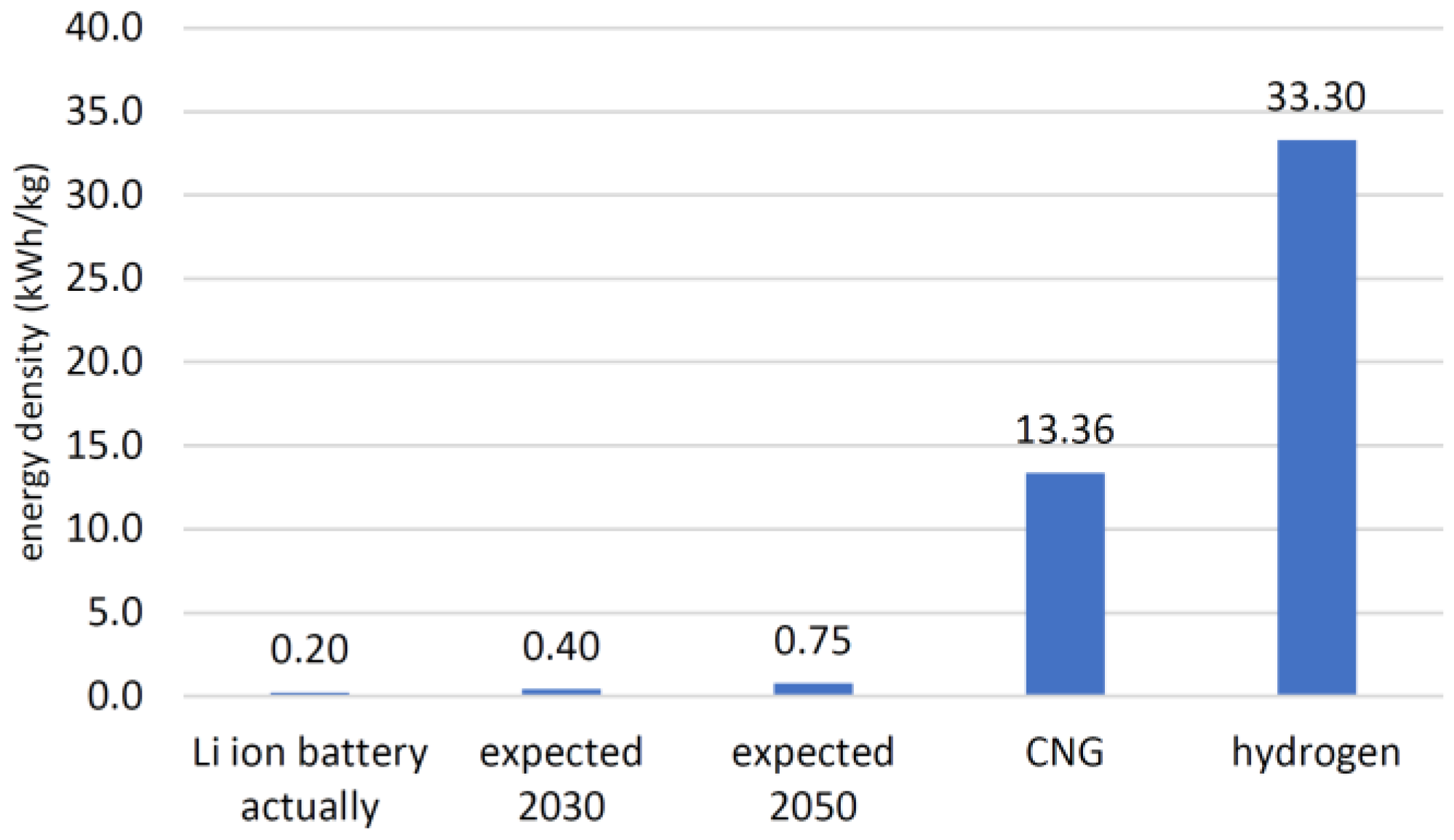
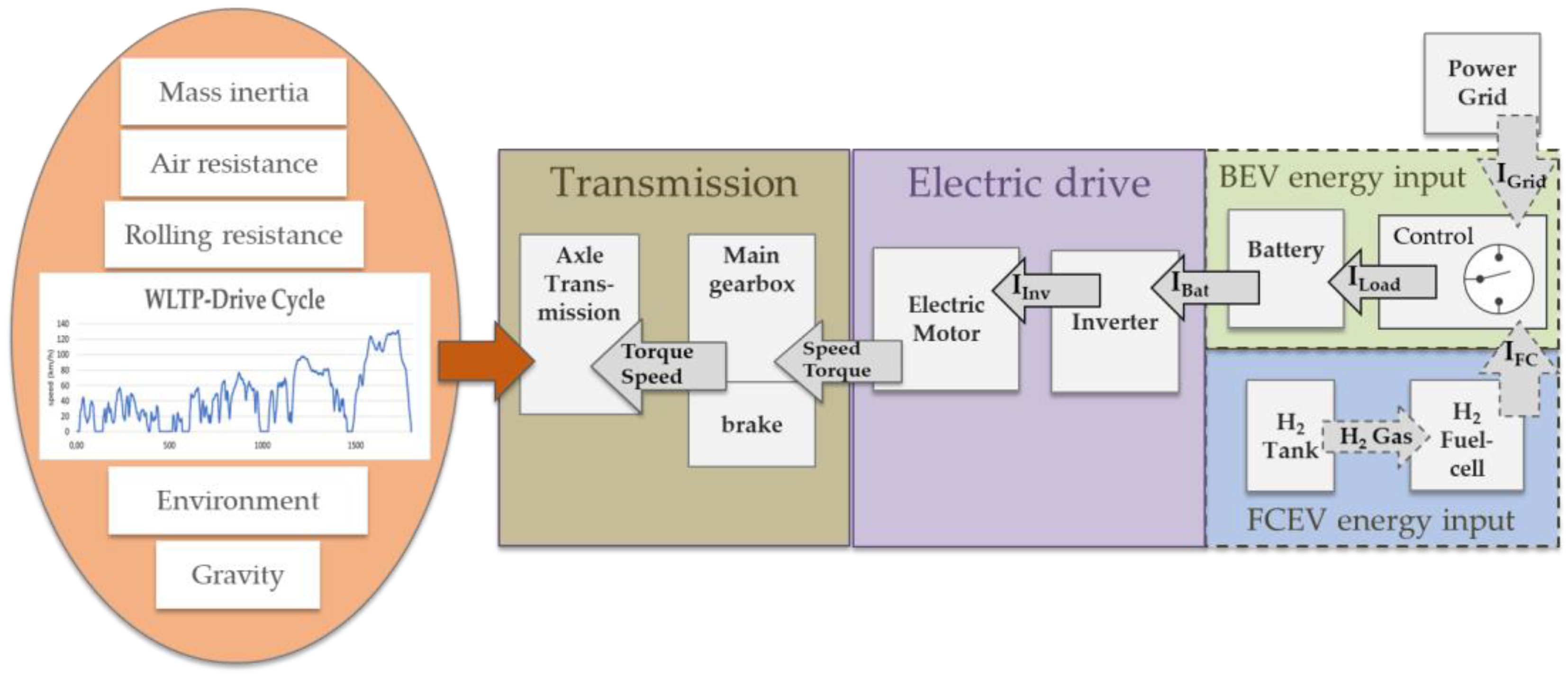
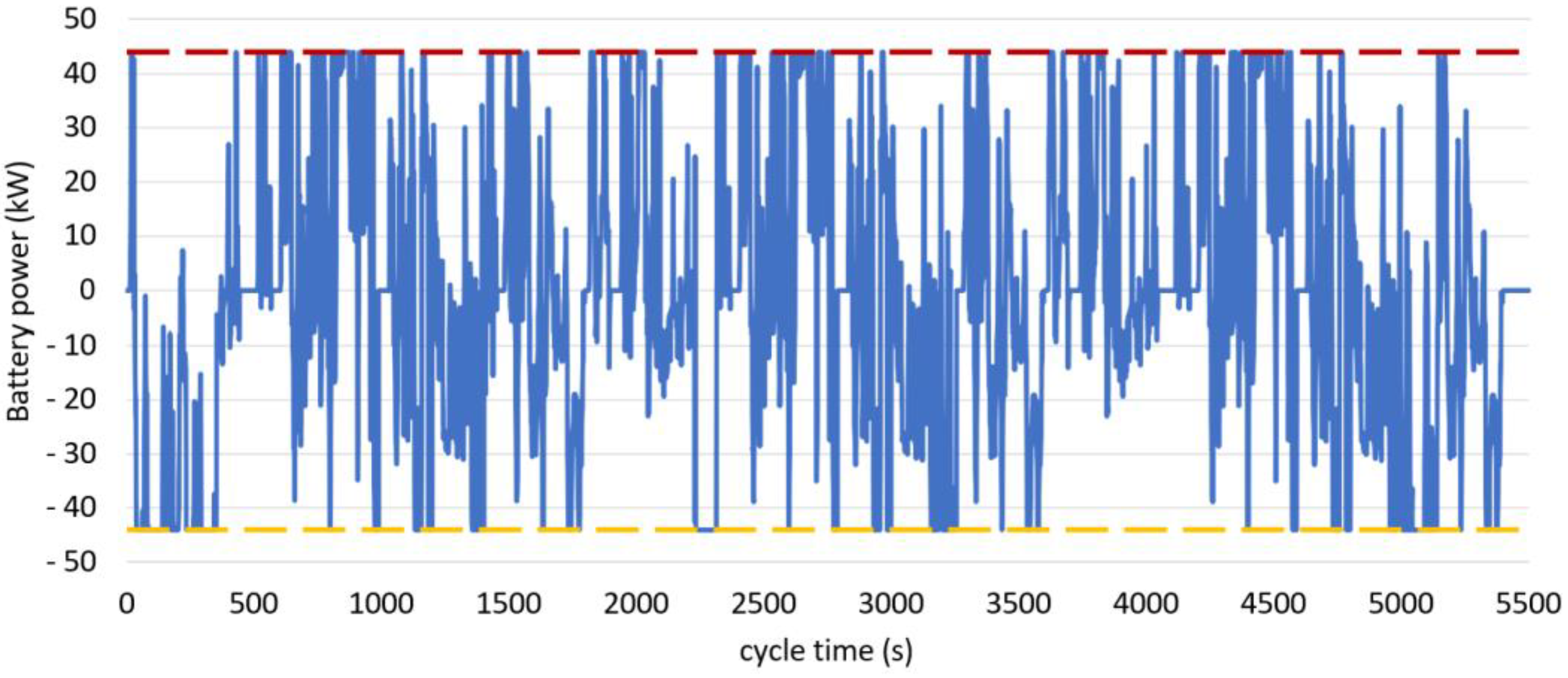
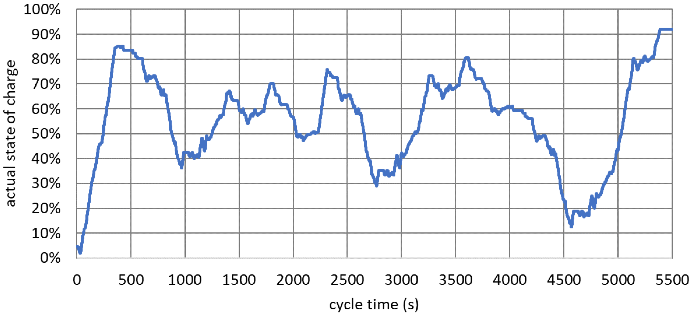
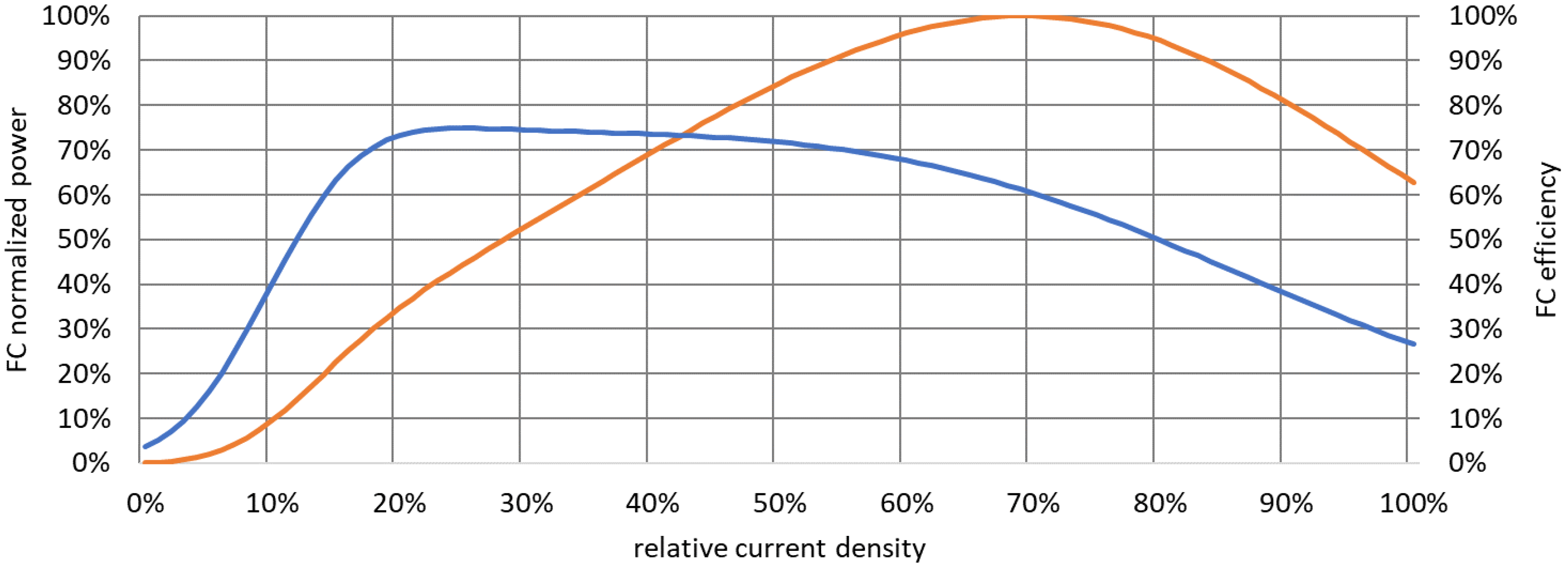
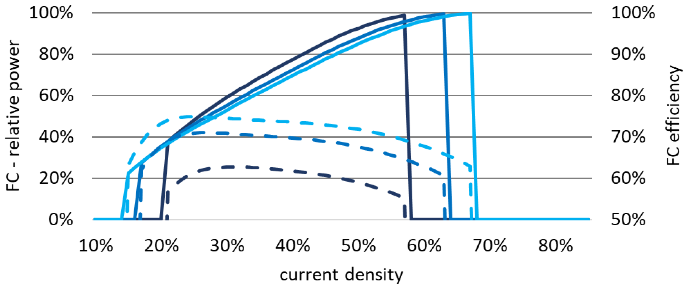
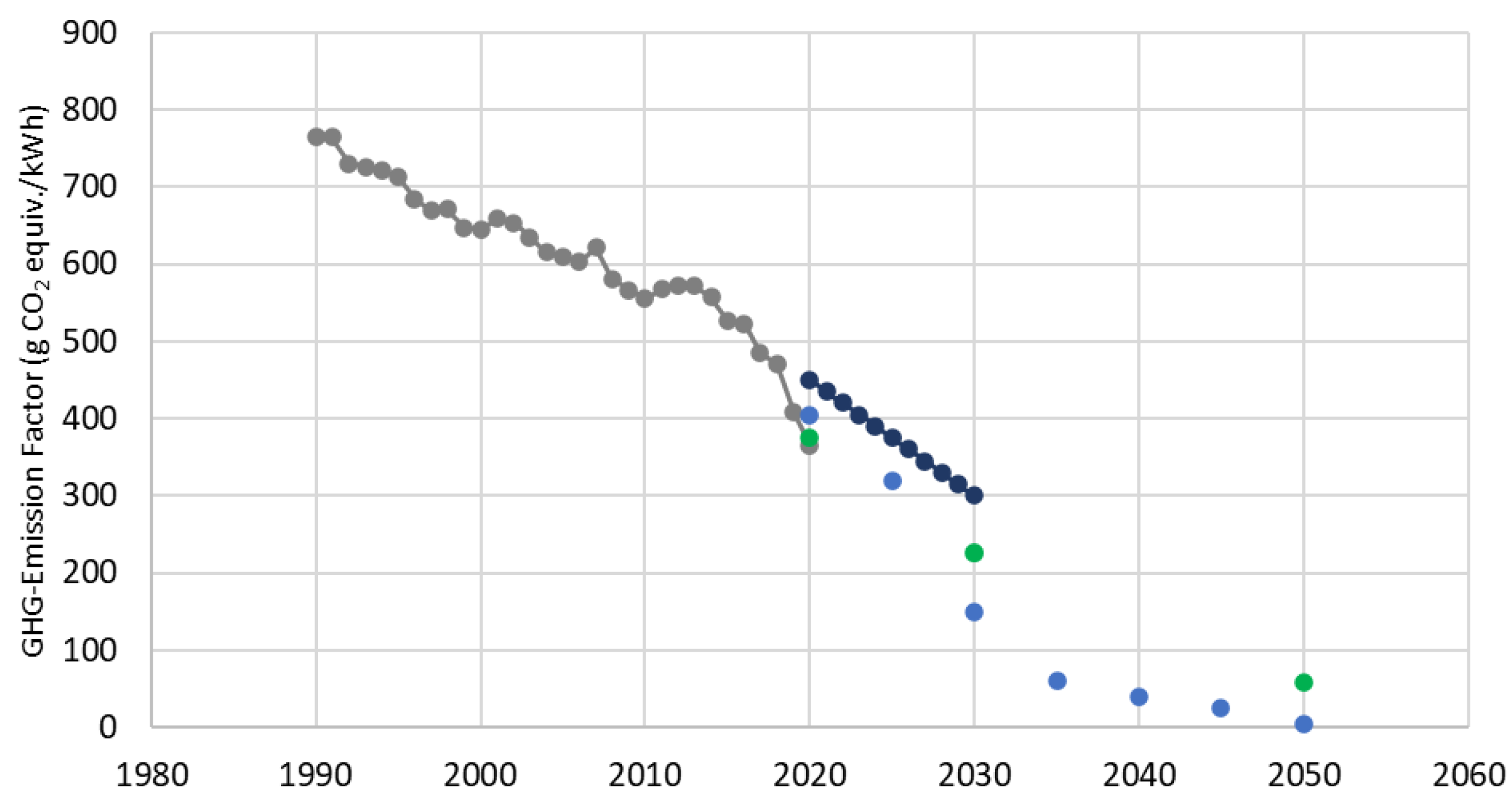
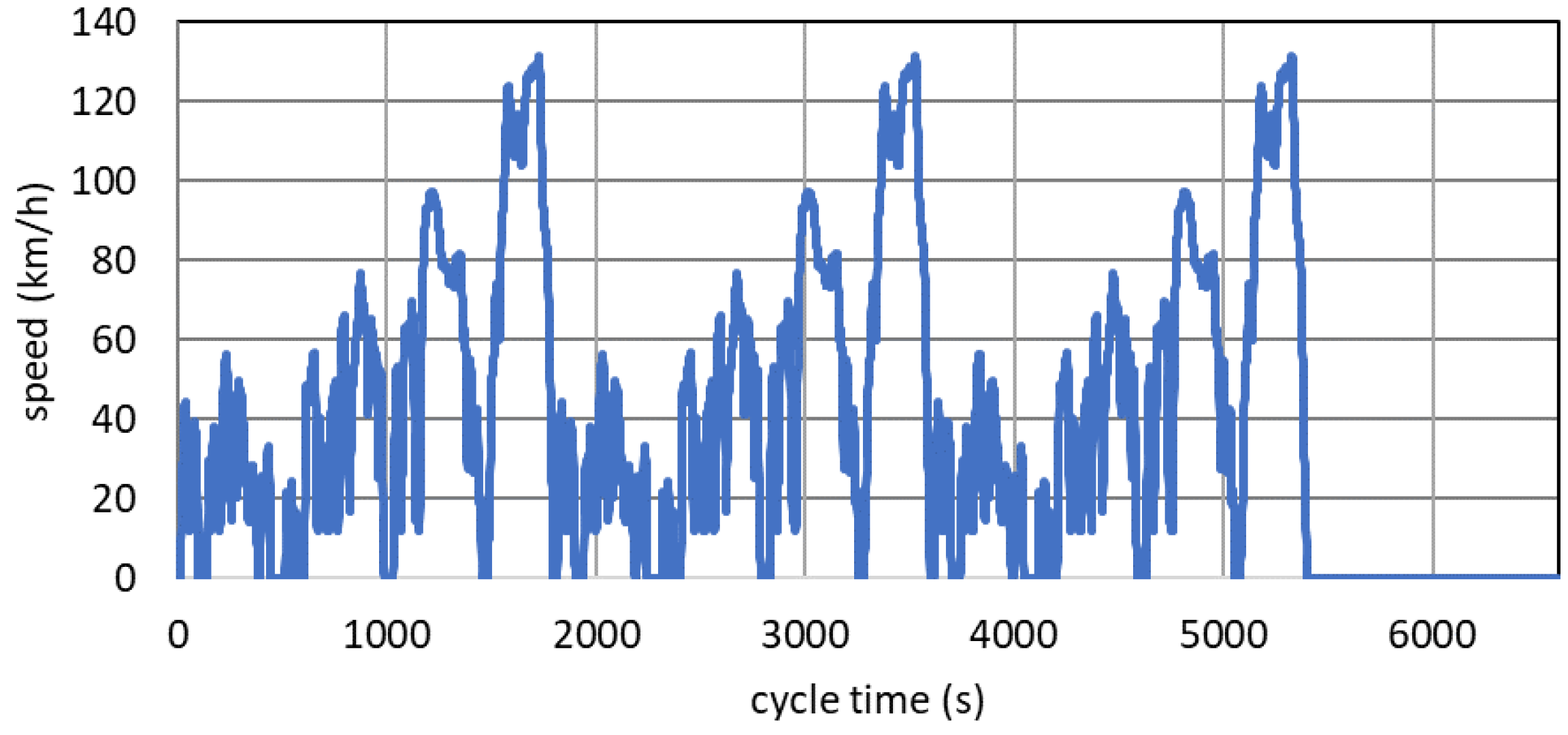
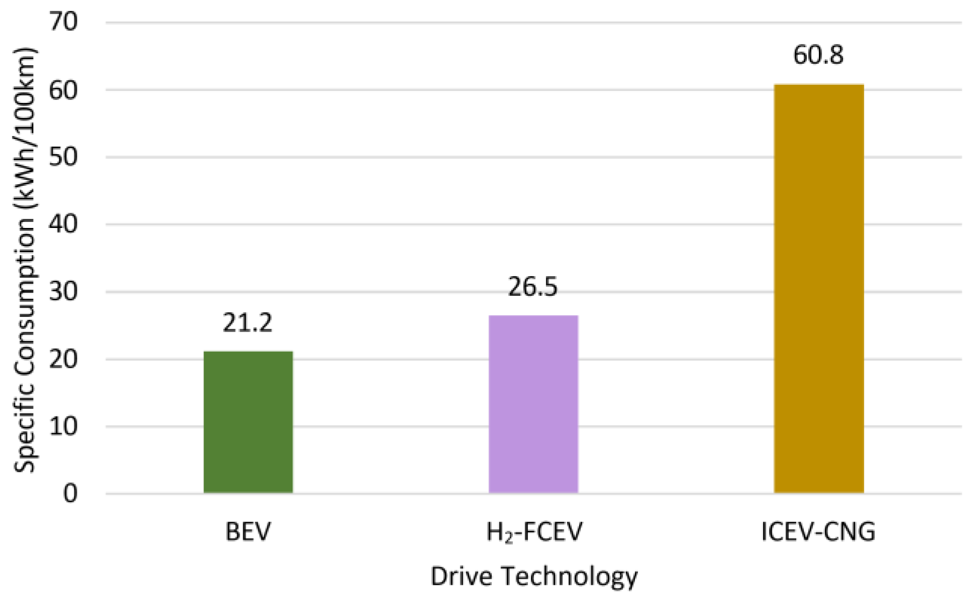
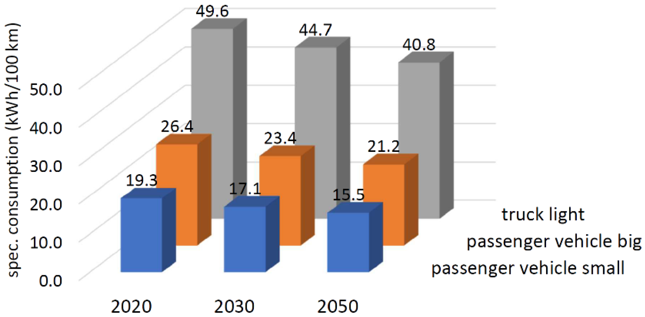
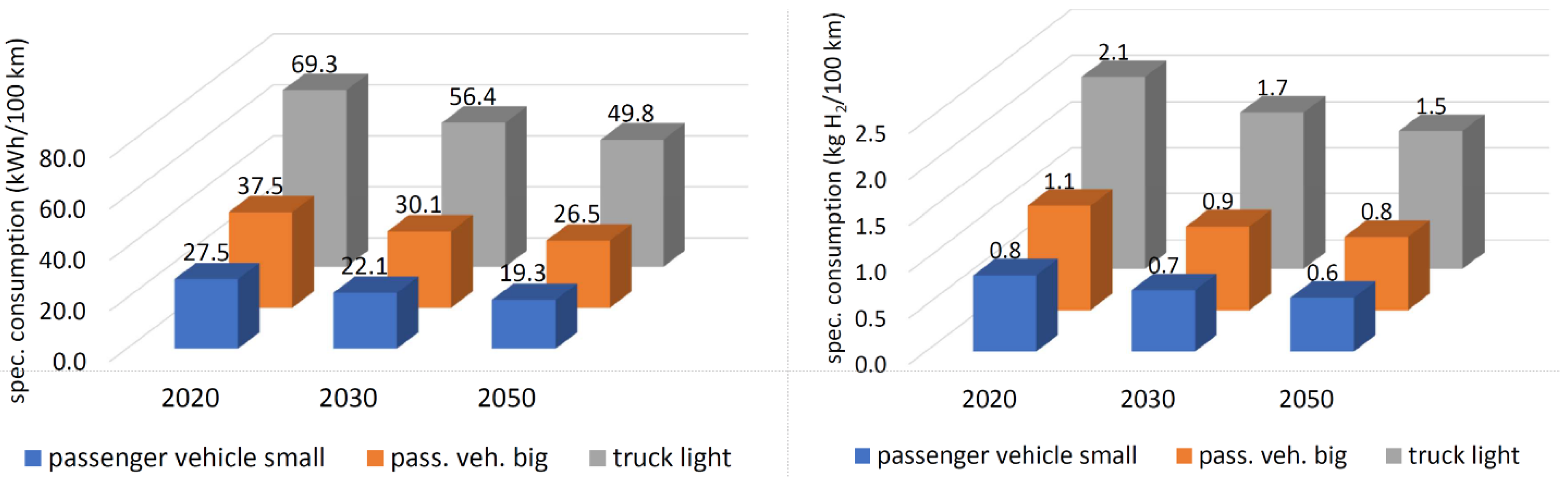
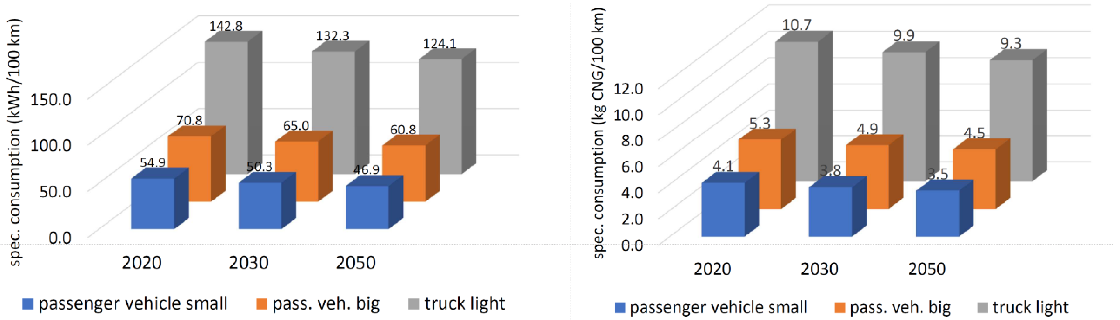
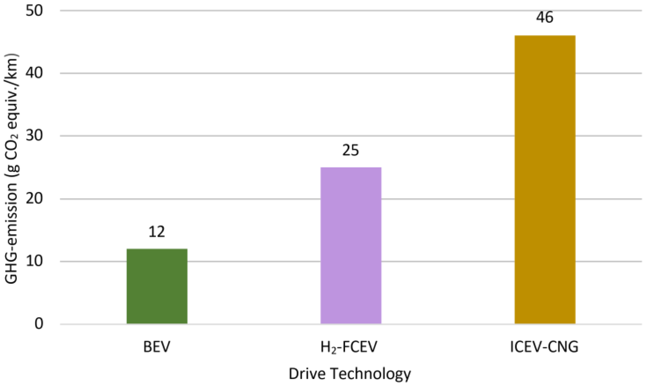
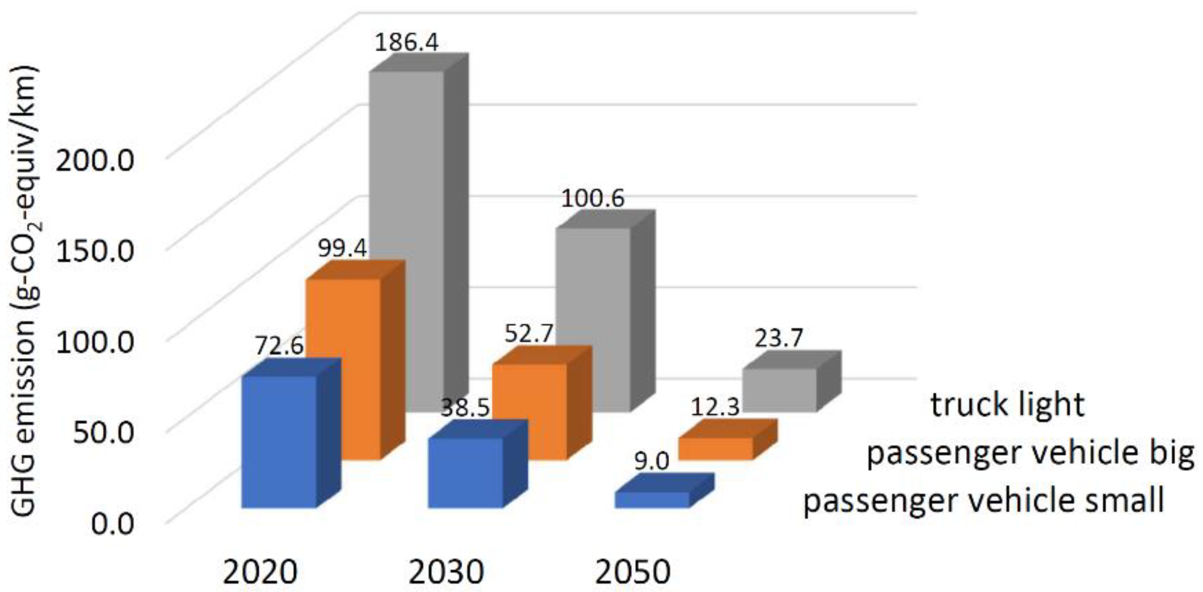
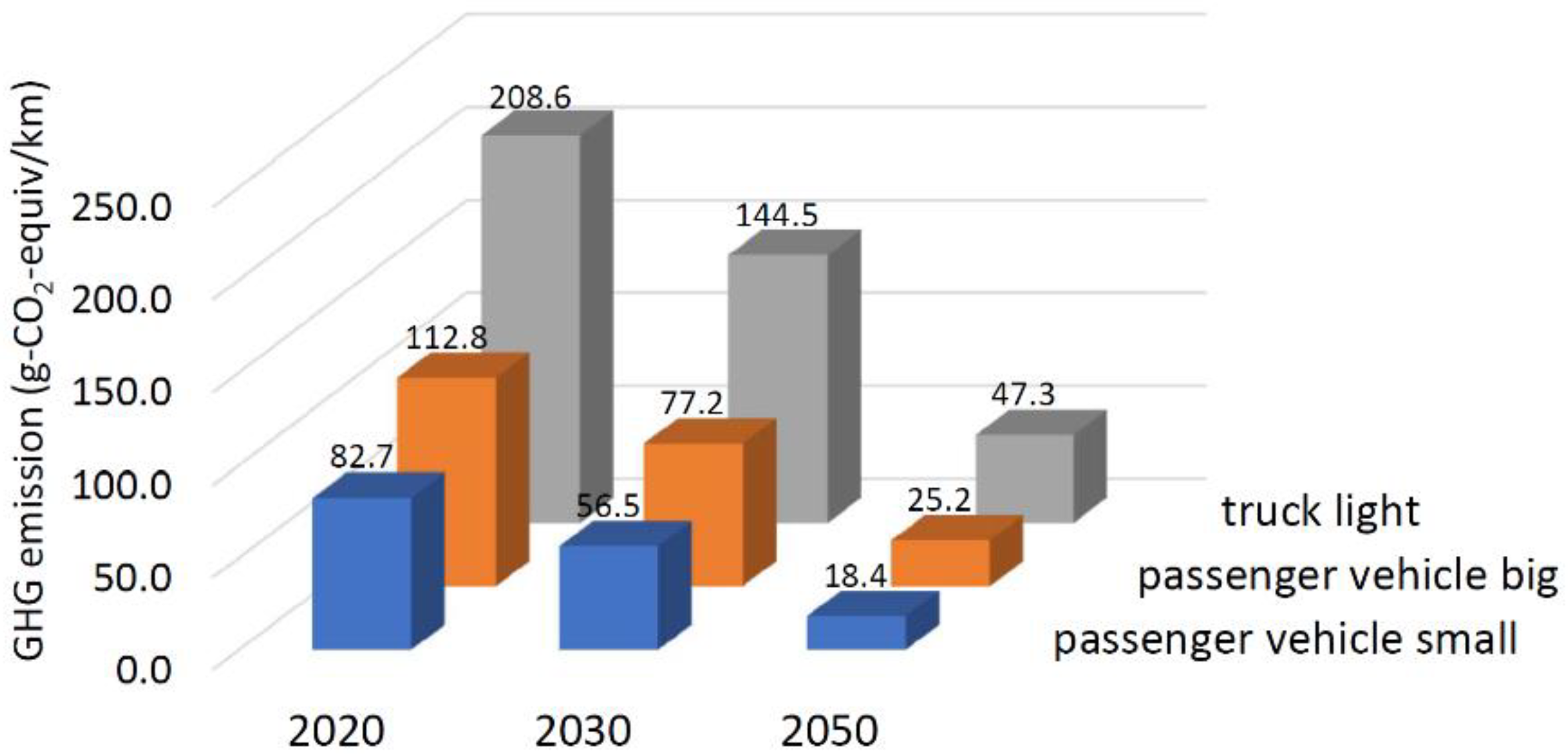
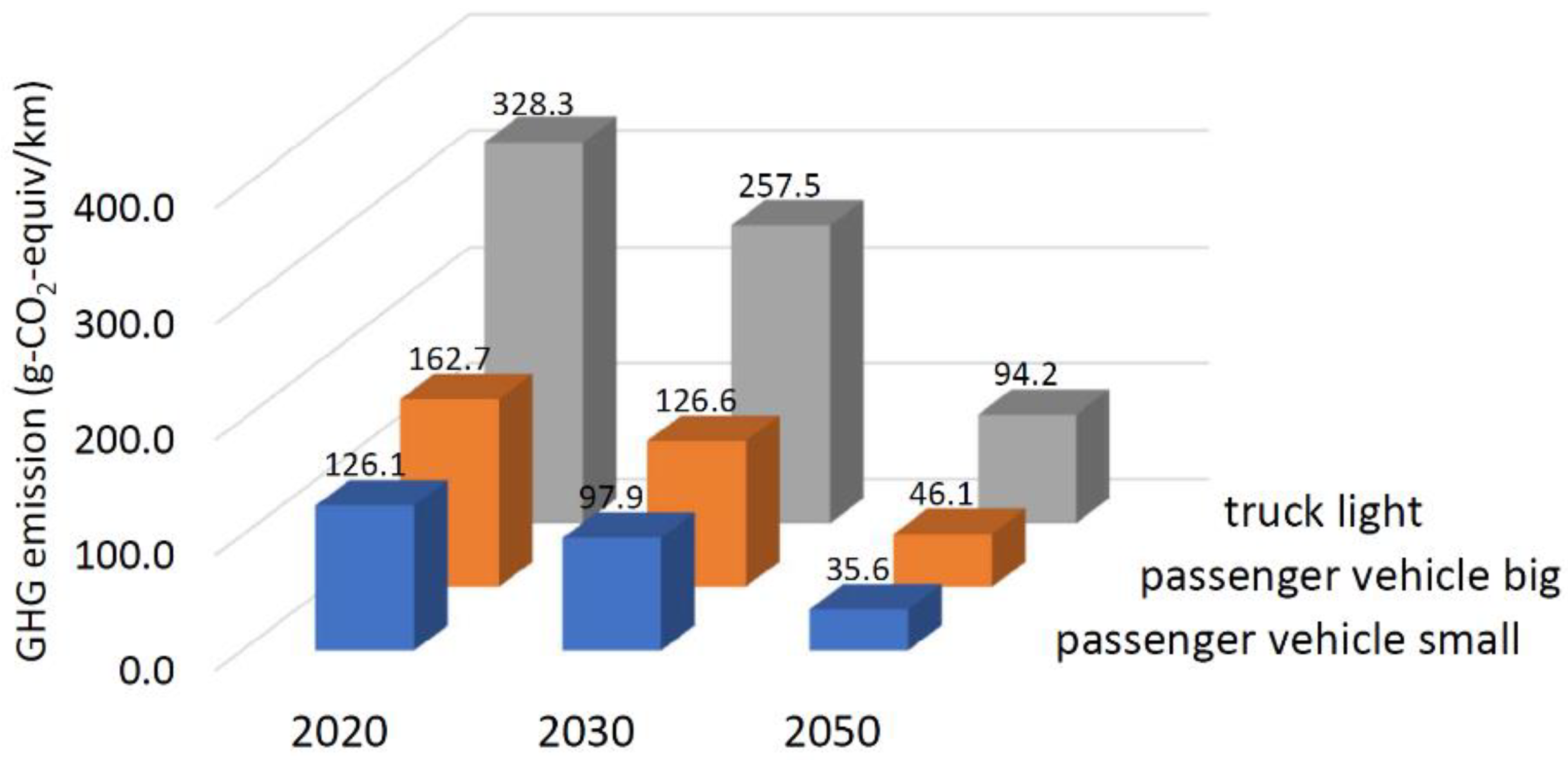
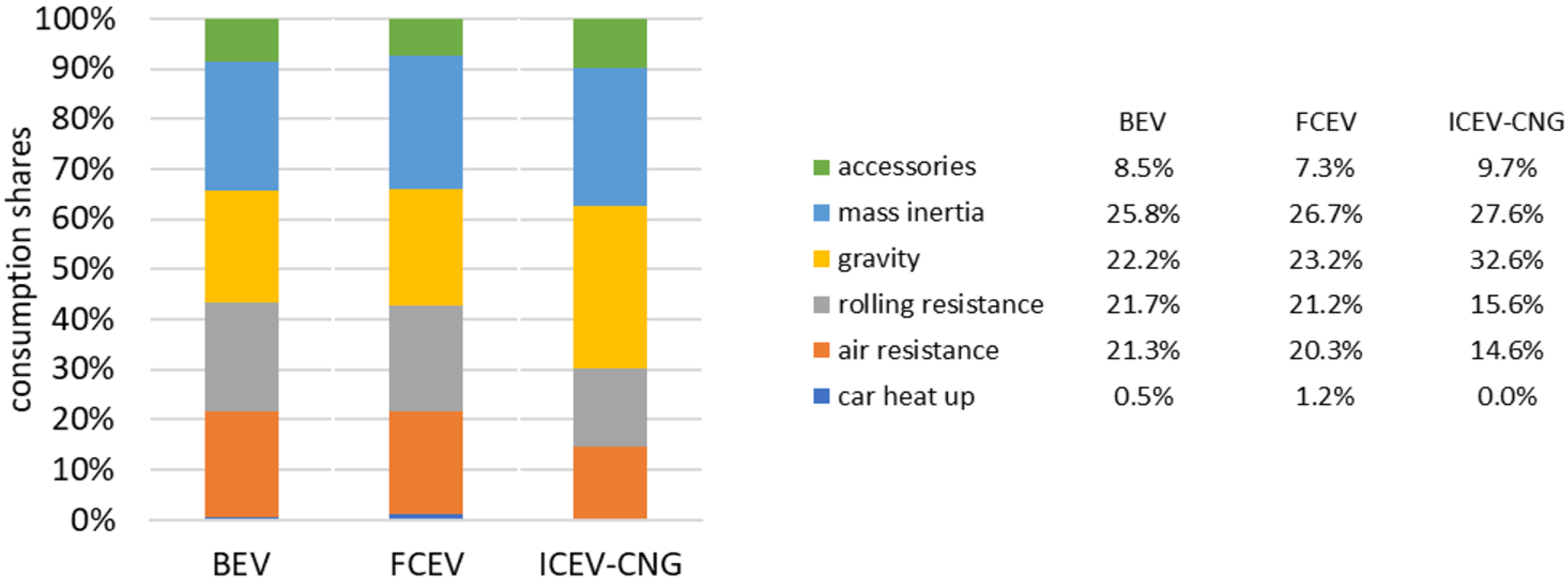
Figure 10.
Specific consumption of large passenger vehicles in 2050 as a function of drive technology (transition season, hilly terrain, and WLTP triple-mixed drive cycle).
Figure 10.
Specific consumption of large passenger vehicles in 2050 as a function of drive technology (transition season, hilly terrain, and WLTP triple-mixed drive cycle).

Figure 11.
Specific consumption of BEVs until 2050.

Figure 12.
Specific consumption of FCEVs until 2050 (in kWh/100 km and kg/100 km).

Figure 13.
Specific consumption of ICEVs–CNG until 2050 (in kWh/100 km and kg/100 km).

Figure 14.
GHG emissions of large passenger vehicles in 2050 as a function of drive technology (transition season, hilly terrain, WLTP triple-mixed drive cycle, and tank to wheel).
Figure 14.
GHG emissions of large passenger vehicles in 2050 as a function of drive technology (transition season, hilly terrain, WLTP triple-mixed drive cycle, and tank to wheel).

Figure 15.
GHG emissions of BEVs until 2050 (tank to wheel).

Figure 16.
GHG emissions of FCEVs until 2050 (tank to wheel).

Figure 17.
GHG emissions of ICEVs–CNG until 2050 (tank to wheel).

Figure 18.
Consumption shares of the investigated drive technologies in 2030 (large passenger vehicle, WLTP cycle, transition season, and hilly terrain).
Figure 18.
Consumption shares of the investigated drive technologies in 2030 (large passenger vehicle, WLTP cycle, transition season, and hilly terrain).

Table 1.
Definition of vehicle classes (further parameters are given in Appendix A).
Table 1.
Definition of vehicle classes (further parameters are given in Appendix A).
| Drive Technology | Parameters | Units | Vehicle Class | ||
|---|---|---|---|---|---|
| Passenger Vehicle Small | Passenger Vehicle Big | Truck Light | |||
| BEV | rated motor power | kW | 80 | 120 | 160 |
| motor type | permanent magnet motor (rare-earth) | ||||
| total weight | t | 1.6 | 2.1 | 4.7 | |
| battery type | Li-FePO4 | ||||
| battery capacity | kWh | 60 | 90 | 120 | |
| FCEV | rated motor power | kW | 80 | 120 | 160 |
| rated FC power | kW | 57 | 99 | 132 | |
| fuel cell type | PEM (proton exchange membrane) | ||||
| rated battery power | kW | 31 | 33 | 44 | |
| total weight | t | 1.6 | 2.0 | 4.6 | |
| battery capacity | kWh | 20.5 | 22 | 29.3 | |
| tank volume | kg H2 | 5 | 8 | 10 | |
| ICEV–CNG | rated motor power | kW | 100 | 140 | 200 |
| total weight | t | 1.4 | 1.7 | 4.2 | |
| tank volume | kg CNG | 15 | 20 | 40 | |
Table 2.
Major drive and energy storage technologies used in the simulation model.
| Acronym | Drive | Energy Storage |
|---|---|---|
| BEV | Electric motor | Battery |
| FCEV | Electric motor | H2 fuel cell with tank and battery |
| ICEV–CNG | ICEV running on CNG | CNG tank |
| FC Type | Fuel | Power Range (kW) | Temperature Range (°C) | Efficiency Range (%) |
|---|---|---|---|---|
| A-FC | H2 | 10–100 | 150–200 | 40–60 |
| PEM-FC | H2 | 0.1–500 | 10–100 | 35–60 |
| DM-FC | CH3OH | 0–100 | 60–130 | 40 |
| PA-FC | H2 | −10,000 | 110–220 | 38–40 |
| MC-FC | H2, CH4 | −100,000 | 550–700 | 48–70 |
| SO-FC | H2, CH4 | >100,000 | 450–1000 | 47–70 |
Table 4.
ICEV–CNG technical data used in the simulation (2020 state of the art).
| Drive Technology | Parameter | Unit | Passenger Small | Vehicle Big | Truck Light |
|---|---|---|---|---|---|
| ICEV–CNG | rated motor power | kW | 100 | 140 | 200 |
| max. torque | Nm | 125 | 175 | 250 | |
| max. motor speed | 1/min | 6000 | 6000 | 6000 | |
| max. efficiency | 39% | 39% | 39% | ||
| total weight | kg | 1362 | 1689 | 4210 | |
| payload | kg | 25 | 40 | 1750 | |
| reduction in axle gearbox | 3.0 | 3.0 | 3.5 | ||
| number of stages main gearbox | 9 | 9 | 9 | ||
| reduction range main gearbox | 1–6 | 1–6 | 1–7 | ||
| tank volume | kg CNG | 15 | 20 | 40 |
Table 5.
Technology areas to be examined.
| Physical Force | Motor Technology | Motor Control | Energy Storage |
|---|---|---|---|
| Air resistance Rolling resistance Weight | Electric motor CNG engine | Inverter | Battery Fuel cell |
Table 6.
The expected increase in battery energy density.
| Energy Density | Unit | Year | ||
|---|---|---|---|---|
| 2020 | 2030 | 2050 | ||
| Gravimetric | Wh/kg | 200 | 400 | 750 |
| Volumetric | Wh/L | 500 | 750 | 1100 |
Table 7.
The expected increase in FC power density and efficiency.
| PEM-FC Feature | Unit | Year | ||
|---|---|---|---|---|
| 2020 | 2030 | 2050 | ||
| Power density | kW/kg | 0.5 | 1.0 | 1.5 |
| Efficiency max. | — | 63% | 71% | 75% |
Table 8.
Calculated GHG emission factors of the relevant energy sources/ fuels.
| Energy Source | Emissions in g CO2-eq./kWh by Year | ||
|---|---|---|---|
| 2020 | 2030 | 2050 | |
| Electricity | 376 | 225 | 58 |
| H2 | 301 | 256 | 95 |
| CNG | 230 | 195 | 76 |
| Primary Energy Source | Share in the Electricity Production by Year | |||
|---|---|---|---|---|
| 2020 | 2030 | 2050 | ||
| Fossil | Lignite | 19.2% | 10.4% | 0.3% |
| Hard coal | 10.3% | 4.8% | 0.8% | |
| Nuclear | 10.3% | 0.0% | 0.0% | |
| Natural gas (GST) | 2.8% | 2.9% | 1.7% | |
| Natural gas (CoGen) | 11.1% | 10.7% | 9.9% | |
| Regenerative | Wind onshore | 17.4% | 32.6% | 40.4% |
| Wind offshore | 4.0% | 10.6% | 12.2% | |
| Hydropower | 3.4% | 3.0% | 2.4% | |
| Biomass | 6.0% | 4.9% | 4.5% | |
| Photovoltaic | 9.1% | 18.0% | 23.2% | |
| Other | 6.3% | 1.1% | 4.5% | |
| Total | Relative | 100.0% | 100.0% | 100.0% |
| Absolute | 593 TWh | 740 TWh | 997 TWh | |
| Primary Energy Source | GHG Factors in g CO2-eq./kWh by Year | |||
|---|---|---|---|---|
| 2020 | 2030 | 2050 | ||
| Fossil | Lignite | 1142 | 1142 | 1142 |
| Hard coal | 815 | 815 | 815 | |
| Nuclear | 32 | 32 | 32 | |
| Natural gas (GST) | 370 | 365 | 205 | |
| Natural gas (CoGen) | 370 | 365 | 205 | |
| Regenerative | Wind onshore | 18 | 18 | 18 |
| Wind offshore | 17 | 17 | 17 | |
| Hydropower | 40 | 40 | 40 | |
| Biomass | 0 | 0 | 0 | |
| Photovoltaic | 50 | 45 | 34 | |
| Other | 125 | 125 | 125 | |
| Total | 376 | 225 | 58 | |
| Process | H2 Production Share by Year, in % | GHG Emission Factor by Year, in g CO2-eq./kWh | ||||
|---|---|---|---|---|---|---|
| 2020 | 2030 | 2050 | 2020 | 2030 | 2050 | |
| Hard coal | 10 | 10 | 0 | 570 | 570 | 570 |
| Crude oil | 15 | 10 | 0 | 360 | 360 | 360 |
| Methane | 35 | 15 | 0 | 329 | 312 | 312 |
| Methane + CCS | 30 | 20 | 20 | 152 | 130 | 130 |
| Electrolysis–regenerative | 5 | 20 | 0 | 31 | 30 | 27 |
| Electrolysis–electricity | 5 | 25 | 80 | 546 | 336 | 86 |
| Total | 100 | 100 | 100 | 301 | 256 | 95 |
| Process | GHG Emission Factor by Year, in g CO2-eq./kWh | ||
|---|---|---|---|
| 2020 | 2030 | 2050 | |
| Fossil | 374 | 374 | 374 |
| Power-to-gas | 820 | 641 | 134 |
| Biomass | 14 | 14 | 14 |
| Total generation mix | 230 | 195 | 76 |
Table 15.
Reduction in consumption by recuperation from 2020 to 2050 (large passenger car, WLTP triple-mixed cycle, transition season, and hilly terrain).
Table 15.
Reduction in consumption by recuperation from 2020 to 2050 (large passenger car, WLTP triple-mixed cycle, transition season, and hilly terrain).
| Item | 2020 | 2030 | 2050 | |||
|---|---|---|---|---|---|---|
| BEV | FCEV | BEV | FCEV | BEV | FCEV | |
| Recuperation factor | 67% | 67% | 70% | 69% | 73% | 72% |
| Recuperated energy (kWh) | −3.0 | −2.9 | −2.6 | −2.7 | −2.5 | −2.6 |
| Total energy consumption (kWh) | 18.5 | 26.2 | 16.3 | 21.0 | 14.8 | 18.5 |
| Share of recuperation | 16% | 16% | 16% | 13% | 17% | 14% |
Table 16.
Comparison between experimental data on BEV consumption from the literature and this work.
Table 16.
Comparison between experimental data on BEV consumption from the literature and this work.
| No. | Benchmark Data | Model Predictions (This Work) | |||
|---|---|---|---|---|---|
| Vehicle Type | Consumption (kWh/100 km) | Data Source | Parameter Settings | Consumption (kWh/100 km) | |
| 1 | Toyota bZ4X | 20.1 | Field [72] | Passenger vehicle small, year 2020, WLTP | 19.3 |
| 2 | BMW i4 | 21.8 | Field [72] | Passenger vehicle small, year 2020, WLTP | 19.3 |
| 3 | Tesla Model Y | 23.0 | Field [72] | Passenger vehicle large, year 2020, WLTP | 26.4 |
| 4 | BEV 100 kW | 23.0 | Field [73] | Passenger vehicle medium, year 2020, WLTP | 19.3–26.4 |
Table 17.
Comparison between experimental data on FCEV consumption from the literature and this work.
Table 17.
Comparison between experimental data on FCEV consumption from the literature and this work.
| No. | Benchmark Data | Model Predictions (This Work) | |||
|---|---|---|---|---|---|
| Vehicle Type | Consumption (kWh/100 km) | Data Source | Parameter Settings | Consumption (kWh/100 km) | |
| 1 | Hyundai Nexo | 36.7 | Field [72] | Passenger vehicle large, year 2020, WLTP | 37.5 |
| 2 | Toyota Mirai | 32.3 | Field [72] | Passenger vehicle medium, 2020, WLTP | 27.5–37.5 |
| 3 | Toyota Mirai | 24.0 | Lab. [74] | Passenger vehicle medium, 2020, WLTP | 27.5–37.5 |
Disclaimer/Publisher’s Note: The statements, opinions and data contained in all publications are solely those of the individual author(s) and contributor(s) and not of MDPI and/or the editor(s). MDPI and/or the editor(s) disclaim responsibility for any injury to people or property resulting from any ideas, methods, instructions or products referred to in the content. |
© 2023 by the authors. Licensee MDPI, Basel, Switzerland. This article is an open access article distributed under the terms and conditions of the Creative Commons Attribution (CC BY) license (https://creativecommons.org/licenses/by/4.0/).
Share and Cite
MDPI and ACS Style
Dollinger, M.; Fischerauer, G. Physics-Based Prediction for the Consumption and Emissions of Passenger Vehicles and Light Trucks up to 2050. Energies 2023, 16, 3591. https://doi.org/10.3390/en16083591
AMA Style
Dollinger M, Fischerauer G. Physics-Based Prediction for the Consumption and Emissions of Passenger Vehicles and Light Trucks up to 2050. Energies. 2023; 16(8):3591. https://doi.org/10.3390/en16083591
Chicago/Turabian StyleDollinger, Manfred, and Gerhard Fischerauer. 2023. "Physics-Based Prediction for the Consumption and Emissions of Passenger Vehicles and Light Trucks up to 2050" Energies 16, no. 8: 3591. https://doi.org/10.3390/en16083591
Note that from the first issue of 2016, this journal uses article numbers instead of page numbers. See further details here.