


Recent Advances in High-Temperature Steam Electrolysis with Solid Oxide Electrolysers for Green Hydrogen Production


1
School of Metallurgy and Materials Engineering, Iran University of Science and Technology, Tehran 16846-13114, Iran
2
School of Chemistry and Chemical Engineering, University of Surrey, Guildford GU2 7XH, UK
3
Department of Mechanical Engineering, Ankara Yildirim Beyazit University, Ankara 06010, Turkey
4
Faculty of Engineering and Applied Science, Ontario Tech University, Oshawa, ON LG1 0C5, Canada
5
Faculty of Engineering, Mansoura University, Mansoura 35516, Egypt
*
Author to whom correspondence should be addressed.
Energies 2023, 16(8), 3327; https://doi.org/10.3390/en16083327
Submission received: 19 February 2023
/
Revised: 1 April 2023
/
Accepted: 4 April 2023
/
Published: 8 April 2023
(This article belongs to the Topic Hydrogen Production Processes)
Abstract
:Hydrogen is known to be the carbon-neutral alternative energy carrier with the highest energy density. Currently, more than 95% of hydrogen production technologies rely on fossil fuels, resulting in greenhouse gas emissions. Water electrolysis is one of the most widely used technologies for hydrogen generation. Nuclear power, a renewable energy source, can provide the heat needed for the process of steam electrolysis for clean hydrogen production. This review paper analyses the recent progress in hydrogen generation via high-temperature steam electrolysis through solid oxide electrolysis cells using nuclear thermal energy. Protons and oxygen-ions conducting solid oxide electrolysis processes are discussed in this paper. The scope of this review report covers a broad range, including the recent advances in material development for each component (i.e., hydrogen electrode, oxygen electrode, electrolyte, interconnect, and sealant), degradation mechanisms, and countermeasures to mitigate them.
1. Introduction
Future environmental security and economic growth greatly rely on answering the continually increasing energy demand in different sectors, such as buildings (commercial and residential), transportation, and industrial sectors. Although the energy consumption rate declined during the context of the global pandemic until 2020, it rebounded with a 5% growth afterwards in 2021. As energy resources dwindle and need rise, several approaches have been proposed to address this demand [1,2,3]. The availability, environmental friendliness, sustainability, and costs of energy have determined the course of human life during the past century. Many energy sources have been unlocked so far, from fossil fuels to nuclear, hydropower, wind energy, biomass, solar energy, etc. Currently, the accelerating energy demand is mainly addressed using the combustion of fossil fuels, such as natural gas, petroleum, etc., which is considered one of the main sources of greenhouse gas (GHG) emissions [2,4,5]. To mitigate the adverse effects of using fossil fuels, a more robust and efficient source of energy must be developed to tackle both the energy and environmental challenges. Solar cells [6], geothermal systems [7], thermoelectric materials [8], biomass [9], fuel cells [2,10], batteries [11], hydrogen energy [12], etc., are among the inexhaustible, cheap, and clean energy systems that can offer economic, environmental, and reliable advantages over fossil fuels [13]. Amongst all of the novel clean energy systems, there is a growing interest in hydrogen as a carbon-neutral alternative that can address both the ever-increasing energy demand and environmental considerations. The strong interest in developing hydrogen production technologies is mainly due to its favourable attributes, such as being the lightest chemical element with the highest energy density, high efficiency, renewability, high conversion, quick recovery, versatility, cleanliness, high overall storage capacity, zero emissions, etc. (Table 1) [13,14,15,16].
Hydrogen plays a crucial role in several chemical industries, such as petroleum, ammonia, oil sands, etc., as well as being a clean transportation fuel, making nitrogen fertilizers, semiconductor manufacturing, pharmaceuticals, aerospace applications, etc. [13,14,17,18]. A scheme of the current and future application of hydrogen is illustrated in Figure 1. As can be seen from the historical transition from fossil fuels to novel fuel consumptions, hydrogen shows great potential for addressing current and future clean energy demand by virtue of its high greenisation factor (GF = 0–1, a factor indicating the amount of GHG emissions, higher values correlates with lower GHG emissions) and other exciting properties [14,19].
Hydrogen is very reactive and does not exist as a molecule; thus, it must be produced by extracting it from other hydrogen-containing sources, such as water, hydrocarbons, carbohydrates, etc. [13,14]. Hydrogen can be generated through diverse resources, including biomass, fossil fuels, water electrolysis, etc. [13,20]. As of today, more than 95% of hydrogen production technologies rely on fossil fuel burning, including natural gas, naphtha reforming, and coal gasification, which requires high energy utilisation and releases significant greenhouse gases [13,21]. There have been remarkable advances in hydrogen production source inputs, including water (e.g., electrolysis, photolysis, and thermolysis) [22,23,24,25], biogas (such as biomethane reforming) [26,27], biomass (e.g., biomass gasification, pyrolysis, and bio-chemical) [28,29,30], coal gasification [31], partial oxidation of liquid hydrocarbons [32], and natural gas (such as steam methane reforming (SMR), autothermal reforming (ATR), chemical looping, partial oxidation (POX), and pyrolysis (methane splitting)) [33,34,35,36,37].
Nuclear energy is considered to be a sustainable and clean energy source and has a strong potential for large-scale hydrogen production. It has been reported that the US Department of Energy (DoE), in cooperation with various laboratories and companies in the USA, has been working on three projects since 2020 [38,39,40]. Although large-scale hydrogen generation based on nuclear power was in its infancy up to around 2003 [39], it attracted great interest during the past decade, and several researchers have focused on addressing the technical obstacles of using nuclear power to improve hydrogen generation and reduce pollution. Hydrogen production via a thermochemical cycle or high-temperature water electrolysis can benefit from the heat generated by the nuclear process. It has been reported that the efficiency of a nuclear power-supported high-temperature electrolysis system has the potential to be near to that of thermochemical cycles without using fossil fuels, GHG emissions, and severe materials corrosion [41]. In this context, steam electrolysis coupled with a solid acid electrolysis cell is an effective approach for hydrogen production at intermediate temperatures (<300 °C) and high efficiency, but water vapour and hydrogen separation needs a separate process [42]. The integration of steam electrolysis with a solid oxide electrolysis cell (SOEC) is another approach for hydrogen production, but it also suffers from unstable electrodes and safety issues [43].
Despite the significant engineering advances obtained in the last couple of decades in developing water-splitting technologies, the commercialised methods currently available for producing green hydrogen (such as alkaline electrolysis and proton-exchange membrane—PEM electrolysis) are still incapable of meeting all the market requirements, which necessitates the development of more robust and cost-effective systems. Other challenges include handling, storage complications, safety issues, transportation difficulties, dependence on fossil fuels, etc. In order to minimise the utilisation of fossil fuels for producing (grey) hydrogen and to meet the Paris Agreement’s priorities, electrolysis of steam is widely considered a viable technique for large-scale applications in the mid-term. Hence, this review aims to critically discuss the application of high-temperature steam electrolysis as a potential clean energy technology and pinpoint the main challenges associated with its commercialisation, such as production costs, electrochemical performance, energy conversion efficiency, etc.
2. Hydrogen Generation Technologies
As mentioned earlier, fossil fuel-based technologies are the most industrial processes for hydrogen generation, among which steam methane reforming (SMR) is the most widely used route, with a high conversion efficiency of about 75–85%, which decreases by 5–14% when integrated with a carbon capture system [44]. The primary feedstock of the SMR process is natural gas, but it should be de-sulphurised and reformed at about 700–825 °C using active carbon. The process of converting methane to hydrogen in this process is based on using heat and pressure in which methane reacts with steam to produce a mixture of hydrogen and carbon monoxide (syngas). Then hydrogen can be separated from carbon monoxide by passing the mixture through a water-gas shift reactor, and the final step is the removal of other impurities such as water, methane, carbon dioxide, and the remaining carbon monoxide (Figure 2) [14,45,46,47,48]. The following reactions take place during this process:
In order to facilitate the reforming process, some catalysts, such as Ni-based catalysts, transition metals (such as Cu, Fe, Co, Ni, etc.), noble metals (such as Ru, Pt, Ir, etc.), and oxide supports (such as Ru/Mg(Al)O, Ni/MgO, Ni.Al2O3, etc.), have been used amongst which Ni-based catalysts are the most widely used materials due to their cost-efficiency and high performance [49]. The existing infrastructure and relatively high efficiency (74–85%) of this technology are the most important advantages of this process, but unstable supply and the production of carbon monoxide and carbon dioxide are the most significant drawbacks of it [50].
Chemical looping is an innovative approach for hydrogen production and carbon capture method that involves the reaction and regeneration of solid chemical materials (fuel). Due to the in situ creation of oxygen, there is no need for an external supply of oxygen, resulting in reducing the operating costs and energy needed for the process [51]. Based on this concept, several techniques have been driven, as seen in Figure 3. Besides these traditional technologies, there are also some relatively new processes, including chemical looping steam methane reforming (CL-SMR or CLRM), steam reforming integrated with chemical looping combustion (SR-CLC or CLR(s)), auto thermal chemical looping reforming (CLR(a)), chemical looping gasification (CLG), oxygen-carrier aided combustion (OCAC), etc. [52,53,54,55]. Among all of the chemical looping systems, chemical looping combustion (CLC) is the most industrial and widely used technology. CLC is highly energy efficient with intrinsic CO2 capture, which can produce hydrogen production with relatively high efficiency. In order to keep the products away from the air (used for the combustion step), oxygen carriers (OCs) continuously circulate between air and fuel reactors and partially or completely oxidise the fuel (Figure 4) [35,52]. Oxygen carriers should have some key properties, including chemical lifetime, suitable mechanical properties, the least possible environmental effect, no toxicity, high oxygen transport capacity, low cost, high tendency to carbon deposition on the surface of OCs, high reactivity with oxygen and other combustible materials, etc. [54]. Generally, OC materials with the highest performance can be divided into five classes, including Fe-, Cu-, Mn-, Co-, and Ni-based compounds, amongst which Ni-based materials exhibit the highest performance. Other OCs candidates are natural OCs (such as FeTiO3), synthetic OCs (Cu0.95Fe0.05AlO4), or other active materials such as NiO, (Mn, Fe)2O3, Al2O3, TiO2, SiO2, MgAl2O4, ZrO2, bentonite, etc. [13,56]. The first step of the process involves an exothermic oxidation reaction of the metal oxide (reaction 4) and supplies the heat needed for the second step (reaction 5). Reactions 6 and 7 take place in air and fuel reactors, respectively [13].
Another developed cycle is the integrated gasification combined cycle (IGCC), in which a gas-turbine-steam power plant is coupled with a coal gasification unit. IGCC uses liquid or solid hydrocarbon fuels to generate electricity in a cleaner process than fossil fuel burning. The removal of undesirable compounds such as mercury, sulphur, and other substances and the production of syngas is performed after converting the solid/liquid fuel to the gas phase [57]. The most developed IGCC system is coupled with a carbon capture system that results in higher plant energy efficiency and lower operational and capital costs. The future of IGCC depends on solving its major technological barriers, such as high operating and capital costs, indicating that it needs additional development prior to commercialisation [58,59].
Coal gasification converts carbonaceous compounds (petroleum, coke, biomass, etc.) into carbon, hydrogen, carbon monoxide (syngas), and a small amount of carbon dioxide and methane [60]. In coal gasification, dry coal reacts with steam and oxygen under high pressure in the gasifier and produces hydrogen and carbon dioxide. Then, air passes through the gasifier and partially oxidises the coal () and generates heat. Next, steam replaces air in the system (water gas shift reaction) and reacts with a part of the coal to separate hydrogen from the coal gas (). After reaching a specific heat level, the air is fed to the gasifier once more [31,44,61]. Underground coal gasification (UCG) is a new type of coal gasification in which the gasification process takes place without mining. In this in situ process, the product gases are mainly carbon monoxide, hydrogen, carbon dioxide, and methane, which are brought up to the surface. The ratio of each gas depends on the depth of the coal mine, pressure, and oxidant balance [59,62]. It should be noted that coal gasification needs high operating temperatures (>900 °C), and different types of coal have been used as feedstock in this process, including anthracites (high rank), bituminous (medium rank), sub-bituminous (low rank), and lignite (low rank) [31,44,63].
Regarding biomass-based hydrogen production technologies, dark fermentation is a simple and facile process that can generate hydrogen at ambient conditions with a simple reactor design and without any need to light, as well as contribute to waste recycling. However, limited hydrogen yield, low efficiency, low conversion efficiency, fatty acid removal, large reactor volume, and high by-product production are the main drawbacks of this process [50,64,65]. Photofermentation is another biomass-based process that can use different wastewater and organic wastes with carbon dioxide neutrality and waste recycling contribution. However, it requires sunlight for the process and low conversion efficiency; the requirement of large reactor volume, low hydrogen production yields and rates, and oxygen sensitivity limited its further development [64,65]. Biomass gasification is the third class of biomass-based hydrogen production technologies. Biomass gasification is a carbon-neutral emission process with copious and cheap feedstock. On the other hand, varying hydrogen production yield (depending on feedstock impurities and seasonal availability) and tar formation are their major disadvantages [14,50,64,66]. Biomass pyrolysis is a developed process with similar pros and cons to biomass gasification but with relatively lower hydrogen production efficiency [65,66]. Steam reforming of biomass is another developed process with higher efficiency and costs of hydrogen production and carbon co-product formation [64,66]. Hydrothermal liquefaction of biomass seems to have the highest hydrogen production efficiency (~85–90%) with moderate production costs, but nitrogenated compounds may exist in the process, and hydrogen production still depends on the quality of the feedstock [67,68]. Compared to water-based technologies, it seems that biomass-based technologies have almost similar hydrogen yields with higher energy efficiency and lower costs than those of water-based ones [66].
Table 2 provides a summary of different hydrogen production technologies and some of their characteristics. Each of these technologies has some advantages and disadvantages. For example, water splitting using electrolysis is a simple technology with low operating temperature and zero carbon emission, which can be easily coupled with fuel cells. Electric power converts to chemical energy in this process in the form of H2 and O2 as follows [66]:
Despite its simplicity, high hydrogen purity, and other advantages, water splitting technologies require high operating pressure and have relatively low efficiency (~55–80%) as well as high capital costs and challenges with energy storage and transportation compared to those of fossil fuel-based technologies, which limits its large-scale application [50,65,70]. Thermolysis of water offers a clean and sustainable route with no carbon emission and abundant feedstock, but its capital cost is relatively high and also needs a separation step to prevent the recombination into an explosive mixture. Furthermore, this technology has other issues with corrosion problems and element toxicity [50,71,72]. High-temperature water splitting methods using nuclear reactors with near-zero greenhouse gas emissions is another technology for hydrogen production in which nuclear energy powers the hydrogen production process, increases its efficiency, and dramatically reduces pollution [46]. At the high voltage and power, high-temperature electrolysis can sustain its operating temperature (i.e., 600–900 °C) exothermally, allowing the input streams to be provided at much lower temperatures. This operation can allow steam at 150 to 200 °C to be the input stream to the high-temperature steam electrolysis (HTSE) plant, enabling the coupling of HTSE with currently operating nuclear reactors [73]. This technology will be further discussed in the next chapters. Photoelectrolysis needs low operating temperature and pressure but has very low efficiency (~0.06–14%), and the need for a significant surface for this process is still a challenge to photoelectrolysis [65,66,72]. Biophotolysis is another water-splitting technology that consumes carbon dioxide as an input and generates hydrogen at ambient conditions along with oxygen as a by-product, but with low hydrogen yield and efficiency (~10%), the requirement of a large surface area for collecting sunlight, high costs of raw materials, oxygen sensitivity, large reactor, and challenges with controlling different bacteria are the technical challenges that restrict its implementation [50,65,66,72].
As hydrogen is recently receiving great attention among all stakeholders, including decision-makers, politicians, economists, and the general public, colour-based taxonomy has been adopted to indicate the different energy sources used to produce hydrogen (e.g., nuclear, renewable, methane, etc.) [44,74]. Different schemes have been proposed and adopted by different organisations. Such schemes are helpful in highlighting the pathways of hydrogen production to some of the involved stakeholders. However, this approach is not adopted in the current study as this classification and colour-coded indexing of hydrogen is helpful within the scope of research and scientific articles. Other measures of carbon intensity and contribution to climate change mitigation can be utilised in this regard. In addition, the scope of the current review paper does not cover this part as it depends heavily on the energy source used along with the hydrogen technology itself.
Currently, most of the hydrogen produced around the world is blue, grey, and black/brown hydrogen due to their relatively low costs and including more controllable reactions. The hydrogen produced during these processes is mainly used in ammonia production and petrochemical plants. The ever-increasing need for grey and black/brown hydrogen accounts for 6% and 2% of worldwide natural gas and coal, respectively [31,44]. Due to its large coal reserve, most of the black/brown hydrogen (hydrogen generated from coal gasification) is currently produced in China [31]. Hydrogen purity of SMR, ATR, and coal gasification processes are 94%, 93%, and 87%, respectively [75]. Hydrogen generation using fossil fuels coupled with carbon capture and storage facilities has the potential to halve the GHG emissions of coal gasification. However, the problem remains as these hydrogen production technologies generate about 830 Mt CO2 annually. Another important challenge facing fossil fuel-based methods is carbon capturing and storage facilities, which increase capital costs. This heavy dependence on hydrogen production on fossil fuel-based routes means that the current hydrogen production technologies have similar GHG emission challenges [75,76].
Despite all of the advances, the most important challenges that hinder the widespread application of hydrogen production technologies are high costs and low production efficiency, storage, slower availability compared to fossil fuel-based routes, etc. [14,16,77]. Decreasing the GHG footprint is one of the primary goals of promoting hydrogen production technologies, which implies the necessity of switching to low GHG emission methods with a threshold CO2 emission value of about 36.4 gCO2e.MJ−1 [75,78]. Although some hydrogen production technologies, such as SMR, methane pyrolysis, etc., are matured and well-developed, most of the non-fossil fuel-based technologies, such as photofermentation, photoelectrolysis, biophotolysis, etc., still need fundamental research. Thus, the large-scale production of non-fossil fuel-based hydrogen production routes is tied to the technological developments of these methods or the invention of the novel, highly efficient ones.
Hydrogen production using nuclear power (pink/purple hydrogen) has been proposed as a potential candidate for hydrogen production. Nuclear energy can increase efficiency and decrease pollution in comparison with fossil fuel-based technologies [79]. Generally, nuclear power can improve hydrogen generation processes such as electrolysis, steam reforming of methane, and thermochemical water splitting cycles such as sulphur-iodine. Nuclear power is of great interest in the sulphur-iodine water-splitting process mainly because it results in higher hydrogen production efficiency without carbon dioxide emissions [38,39,80,81]. As mentioned earlier, reforming and shift reactions occur in the SMR process, followed by a separation process. These reactions take place in a reactor at about 800–900 °C. The heat needed for this process is usually supplied by burning the excess methane, which reduces the methane needed for the reaction and hydrogen production. The process can also happen in a helium-cooled reactor. A more effective route is to use a nuclear reactor to provide the heat needed for this process. Since the traditional reactor cannot be used for transferring the generated heat, the heat transfers from the nuclear reactor to the main reactor using a heat exchanger-type reactor. However, there are still challenges regarding the linking, diffusing hydrogen through the wall and mixing with the coolant (helium), producing tritium caused by hydrogen diffusion and reducing the hydrogen purity, material considerations, etc., which should be addressed [39]. In the sulphur-iodine cycle (S-I cycle), there are three reactions in which the dissociation of sulphuric acid to water vapour, sulphur dioxide, and oxygen at about 850–900 °C is a high-temperature endothermic reaction. The conjunction of the S-I cycle with nuclear power can improve hydrogen generation. Other thermochemical cycles, such as the Cu-Cl cycle, have also been investigated, but generally, the S-I cycle has higher efficiency and is of greater interest compared to the other cycles [13,38,40,82,83,84,85]. Water electrolysis is the simplest method for hydrogen production with zero GHG emissions and a great potential for electrical peak shaving. While the thermal efficiency of electrolysis is about 25%, electrolysis and electrical power generation efficiencies are about 75% and 30%, respectively. As mentioned earlier, hydrogen production costs and storage/transportation issues are the main challenges [20,84]. Among the three nuclear-powered methods, water electrolysis has the lowest efficiency (~25–45%) compared to SMR (~70%) and S-I cycle (~50%) and the highest capital costs (USD 30.97, USD 11.44, and USD 19.96 per GJ of yearly hydrogen production for water electrolysis, SMR, and SI-cycle, respectively). Integrating electrolysis with nuclear power can provide cheaper electricity for the process and increase its efficiency because of the higher thermal efficiencies of nuclear power plants [39].
At the moment, hydrogen production technology at the commercial scale is dominated by fossil fuel-based methods. In addition to the type of technology, other factors, such as cost of labour, land, raw materials, construction, utility, and product, as well as life cycle, construction time, etc., should also be considered in choosing the proper technology for hydrogen production assessment. According to the thermodynamic analyses, the SMR of natural gas is the most efficient and productive technology due to the larger amount of hydrogen produced than that of the other ones. Techno-economic evaluation of the hydrogen production methods shows that coal gasification and SMR of natural gas are the most developed and cost-effective methods. On the other hand, fossil fuels are exhaustible and scarce and cannot satisfy the ever-growing hydrogen demand in the future. Furthermore, assessing each technology in terms of human and environmental impact, fossil fuel-based hydrogen production technologies, such as SMR of natural gas, show the highest impact on human health and global warming, while non-fossil fuel-based technologies, such as water electrolysis, exhibit the lowest impacts. As thermal or electrical energy is needed for most hydrogen production routes, it results in increased capital costs. Generally, hydrogen production costs of electrolysis are about 10.30 USD.kg−1, which is almost four times higher than that of SMR (~2.27 USD.kg−1) or coal gasification (1.8–2.1 USD.kg−1) [86]. A useful method to reduce the capital costs of hydrogen production is to integrate the hydrogen production technologies (such as electrolysis methods) with a power source, such as photovoltaics, nuclear plants, etc., to supply the heat/electricity needed for the operation and reduce hydrogen production costs.
3. Water Electrolysis
3.1. Low-Temperature Water Electrolysis
There are several water electrolysis routes, including solid oxide electrolysis (SOE) [87], alkaline water electrolysis, and proton-exchange membrane (PEM) electrolysis [50]. The fundamentals of the electrolysis process are briefly discussed in the previous chapter. Generally, water electrolysis can be divided into three categories according to the operating temperature: low-temperature, intermediate-temperature, and high-temperature electrolysis. Low-temperature, intermediate-temperature, and high-temperature electrolysis usually operate at temperatures lower than 300 °C, in the range of 300–700 °C, and higher than 700 °C (below 1000 °C), respectively [69,88,89]. In addition to the conventional water electrolysis process, other low-temperature water electrolysis technologies include alkaline water electrolysis, PEM water electrolysis, and anion exchange membrane (AEM) water electrolysis (AEMWT) (Figure 5) [89,90,91,92].
Alkaline water electrolysis (Figure 5a) is a well-established, low-cost, the most developed electrolysis method, long lifetime, and commercialised process that uses non-noble catalysts. In this process, water splits at the cathode side and produces hydrogen and OH- ions, followed by the OH- ions travelling to the anode side to produce oxygen and water. The electrodes are submerged in the electrolyte, and a diaphragm, which is permeable to water and OH- ions, separates the product gases [69,89,93,94,95,96,97]. The liquid electrolyte in this process is usually KOH or NaOH. The electrode can be either nickel, iron, cobalt, Ni-S-Co, La0.5Sr0.5CoO3, Ni50%Al, Ni73%W25%, Ni-Fe-Mo-Zn, porous Co, RuO2, Raney-Ni-Mo, etc. However, the most widely used electrode is nickel due to its low cost, availability, and high activity. The diaphragm can be porous oxides (such as Ni, NiO, BaTiO3, SrTiO3, etc.) or polymer composites (such as radiation-grafted PTFE, PTFE-ZrO2, polyantimonic acid-PTFE, etc.) [92,94,98]. Addressing some challenges, such as carbonate formation, low current density, low dynamic operation, and low purity of gases, can help further the development of this process. Nickel is a common electrode, and the most commonly used electrolytes in this process are potassium hydroxide and sodium hydroxide [93,99,100,101]. Alkaline water electrolysis operates in the temperature range of 20–90 °C [69,102]. Although this technology has already been commercialised, it still suffers from corrosive electrolyte materials, gas crossover, low efficiency, low current density, etc. [89].
Figure 5.
A schematic of (a) alkaline water electrolysis [63], (b) anion exchange [96], and (c) PEM process [97].

AEM water electrolysis (Figure 5b) is structurally similar to PEM cells except for the membrane, which transports OH− anions instead of H+ protons. Similar to the alkaline water splitting process, OH− anions serve as the charge carrier in anion exchange membrane water electrolysis. AEM water electrolysis shows some advantages over the alkaline and PEM cells, such as no carbonates precipitation, lower ohmic loss, less expensive raw materials (compared to PEM cells), and the use of electrolytes with low concentrations [94,103]. Generally, this technology operates in low concentrations of electrolytes and a temperature range of 20–60 °C. Ni, NiMo, Pt/X, IrOx/IrO2, and NiP are the most common cathode materials, and NiFe oxyhydrates, Ni/CeO2-La2O3, CuCoOx, NiFe, and NiFe2O4 are the most widely used materials for the anode [89,96,104]. Despite all of its advantages, much research has to be carried out to improve its efficiency and durability [89].
In PEM electrolysis (Figure 5c), water splits into H+, O2, and e− at the anode. Then H+ (protons) travels to the cathode through the membrane, while electrons exit from the anode using an external power source and recombine with protons to produce hydrogen [50,69,89]. PEM electrolysis offers a fast response, high energy efficiency (~90%), ultrahigh hydrogen purity, higher hydrogen production rate, high proton conductivity, compact system design, low gas permeability, low thickness, high current density, etc., but it also suffers from high costs of materials, acidic environment, etc. The state-of-the-art electrocatalysts for this process are Pt/Pd and IrO2/RuO2 as cathode and anode catalysts, respectively. It should be noted that different categories of Nafion, such as Nafion-115, Nafion-112, Nafion-117, Nafion-1035, and Nafion-212, are used as membranes in this process [50,95,100,101]. PEM water electrolysis technology operates in temperatures ranging from 40 to 80 °C [102] and has lower hydrogen yield efficiency and lower production costs compared to alkaline water electrolysis. Besides the low hydrogen production efficiency, high costs of raw materials, acidic corrosion environment, limited durability, etc., are the main drawbacks of PEM water electrolysis [69,94]. Comparing these three water-splitting technologies, it seems that anion exchange is still in the lab-scale stage, but alkaline and PEM water-splitting methods have been commercialised but still need further progress to solve their current challenges.
Compared to high-temperature technologies, low-temperature processes offer facile operation, compact and easy design, and higher technology readiness levels (TRLs) (TRL is a means to describe the maturity of a technology for its commercialisation and ranges from 1 to 9. TRL = 1 means the technology is still under research, and TRL = 9 means the technology is fully matured) [69]. However, due to the decreased internal resistance losses as well as improved hydrogen evolution reaction (HER) and oxygen evolution reaction (OER) kinetics, high-temperature water electrolysis is more efficient compared to low-temperature ones [89].
3.2. High-Temperature Steam Electrolysis (HTSE)
Compared to low-temperature water electrolysis, high-temperature electrolysis operates in higher temperatures, from 500–900 °C. Although high-temperature electrolysis or steam electrolysis has not been commercialised so far, it is a promising technology that can electrochemically split steam into H2 and O2 using electricity and heat at high temperatures (usually in the range of 700–900 °C) [84,93]. Steam electrolysis at lower temperatures (500–800 °C) has also been reported in the literature [105]. TRL for HTSE is 7 to 8, and for high-temperature co-electrolysis is 4 to 5 [106]. For HTSE operating at around 700 °C, heat resembles around 25% of the total energy input [73]. The electricity needed for HTSE is about 35% lower than that of conventional electrolysis at low temperatures (<80 °C) because the required electricity decreases with increasing temperature. Generally, the efficiency of electricity-to-hydrogen conversion is about 90%, but the highest overall hydrogen production efficiency of this technology is about 50% at 900 °C. It has also been reported that [79] electricity can be used to provide the needed thermal energy when the high-temperature electrolysis unit is on standby to keep the stack at its high operating temperature. This will reduce the star-tup time for large-scale operations [107]. Nuclear power plants can provide heat and electricity for low-cost hydrogen production [108].
Solid oxide electrolysis (SOE) of steam is a well-known high-temperature electrochemical process. SOEs can electrochemically produce hydrogen and are usually comprised of an anode for oxygen generation by an electric potential of around 1.3 V, a cathode for hydrogen generation (or in some cases, CO2 electro-reduction), and an oxygen-conducting electrolyte [79,109]. Similar to the other electrolysis technologies, steam splits into H2 and O2 at the interface between the hydrogen electrode and electrolyte. Then, oxygen ions transfer to the anode side through the electrolyte and recombine at the interface between the oxygen electrode and electrolyte to produce oxygen gas. The operation of SOEC is the reverse operation of SOFC (Figure 6) [79,110]. Solid oxide electrolysis is a developing technology that benefits from its high efficiency, and the most commonly used catalysts are non-noble materials. The electrolyte is usually a ceramic material, and a composite of yttria-stabilised zirconia (YSZ) or Ni-based cermets are the most widely used electrode materials. Half-cell reactions in a solid oxide water electrolyser at the cathode side (hydrogen evolution reaction (HER) or cathode half-cell reaction) and the anode side (oxygen evolution reaction (OER) or anode half-cell reaction) are as follows: [43,69,87,101].
High-temperature water electrolysis technologies can be divided into three main classes, namely proton-conducting solid oxide electrolysis cell (H-SOEC or protonic ceramic electrolysis cell (PCEC)), oxygen ion-conducting solid oxide electrolysis cell (O-SOEC), and co-electrocatalysis of carbon dioxide and steam [84,89,93]. As mentioned earlier, due to the enhanced HER and OER kinetics as well as lower internal resistance losses, high-temperature water electrolysis technologies operate at higher efficiency compared to PEM or Alkaline electrolysis [89]. However, as will be discussed further in the upcoming section, high-temperature electrolysis has some technical issues, including rapid cell degradation, which is the main reason for the limited number of projects considering this technology today. Furthermore, regulatory issues regarding the coupling with a nuclear thermal energy source—as nuclear heat is one of the primary candidates to drive high-temperature electrolysers for large-scale clean hydrogen production—are still to be addressed. It is worth mentioning that ongoing demonstration projects considering the coupling of high-temperature electrolysis with nuclear reactors work through the regulatory process and investigate the regulatory and licensing needs of large-scale plants.
The architecture of a SOEC is comprised of four constituents, including the hydrogen (steam) cathode, the oxygen (air) electrode, the electrolyte, and the intermediate layer (barrier layer) between the oxygen electrode and electrolyte. The interconnect layer is another component that is used in a stack of cells [69,111]. Hydrogen generation occurs in the hydrogen electrode and at the interface between the electrode and electrolyte. Thus, the cathode should be a porous material with electronic and ionic conductivity [111]. Similar to SOFCs, this reaction takes place at the triple phase boundaries (TPBs) where the ionic phase (oxygen ion conductive), the electrical phase (e-conductive), and the gas (hydrogen release or steam supply) meet [112,113]. Oxygen ions are oxidised at the oxygen electrode to produce oxygen gas. This reaction occurs at the interface between the oxygen electrode and electrolyte. Similar to the hydrogen electrode, the oxygen electrode should be comprised of a porous compound. Suitable thermal and chemical compatibility over time, as well as high electrocatalytic activity, high electronic and ionic conductivity, etc., are the most important features of the oxygen electrode [114]. The most common materials for the oxygen layer are Sr-based and Co-based perovskites, such as (La, Sr)(Co, Fe)O3 and La0.8Sr0.2MnO3−δ. Mixed ionic electronic conductive (MIEC) materials, such as LSCF (with electronic and ionic conductivities of about 102 and 10−2 S.cm−1 at 800 °C, respectively), are a new class of oxygen electrode materials [115]. An intermediate layer is usually used between the oxygen electrode and the electrolyte to achieve suitable thermal and chemical compatibility between the two layers. One of the most important issues regarding the cell assembly is the thermal expansion coefficient (TEC) mismatch between the layers, which can increase ohmic resistance due to the weakened mass transfer and charge exchange [2]. In the case of using Co- and Sr-based materials, the volatility of Co during sintering [116] and segregation of Sr during operation [117] can increase cell degradation and reduce cell performance. The main function of this barrier layer is to prevent unwanted element migration and mitigate the mentioned challenges. The common intermediate materials are yttrium-doped ceria (YDC) and gadolinium-doped ceria (GDC or CGO) [113,115]. Another approach is to use composite materials such as LSM-YSZ as oxygen electrodes and avoid using the intermediate layer [111]. The composition of the electrodes (and the intermediate layer) depends on the composition of the electrolyte. The electrolyte layer must be sufficiently dense to prevent gas transport between the electrodes. High oxygen ion conductivity, no electronic conductivity, matching TEC, as well as suitable mechanical, thermal, and chemical stability, are other important characteristics of the electrolyte [2]. The most commonly used electrolyte materials are 8YSZ with high ionic conductivity of about 10−2–10−1 S.cm−1 (700–850 °C). GDC is another candidate with high ionic conductivity but suffers from high sintering temperature (1500 °C), which prevents co-sintering of the layers and reduction in Ce4+ at higher temperatures (>700 °C) in reducing atmosphere [2,118]. In SOEC stacks, the interconnect layer plays an important role as a current collector and a physical barrier that separates the electrodes between the two adjacent cells. The interconnect should meet some technical requirements such as matching TEC to other layers, high thermal and electrical conductivities, formation of a dense low-resistive oxide layer in redox atmospheres, and high thermomechanical at elevated temperatures (600–900 °C) [2,119]. The noteworthy interconnect materials are Cr-alloys and high Cr-containing stainless steel. Crofer 22 APU is the leading interconnect material, a Fe-Cr stainless steel alloy with low cost, high thermal conductivity, and ease of fabrication. Cr-alloys, such as CFY, Ducralloy, CrFe5, etc., are the other promising candidates [41,120,121,122]. Interconnect performance and durability challenges of the SOECs, such as coking, delamination, cracks, etc., are similar to SOFCs.
As discussed earlier, SOECs can be divided into three different classes: (a) O-SOEC, (b) H-SOEC, and (c) hybrid SOEC. A schematic diagram of different types of SOECs is shown in Figure 7. In O-SOEC (Figure 7a), hydrogen is generated from the electrolysis of water at the hydrogen electrode, while protons are produced by water electrolysis in the air electrode and then transferred through the proton-conducting electrolyte to produce hydrogen at the hydrogen electrode in H-SOEC [105,110,112,123]. Compared to the H-SOECs with proton-conducting electrolytes, O-SEOCs exploit oxygen ion-conducting materials and different principles. In O-SOECs, O2− ions are transported from the hydrogen electrode to the air electrode, while steam is fed to the hydrogen electrode. Thus, an additional drying process is needed for the hydrogen produced in O-SOECs [119].
Due to interlayer diffusion, inferior long-term stability, and problems with materials selection/fabrication, the commercialisation of O-SOEC has faced critical challenges. Thus, due to the lower costs of materials, intermediate to low operating temperatures, higher purity of hydrogen, fewer auxiliary components (such as sealant and interconnect), lower activation energy, easier gas separation, etc., H-SOECs have received particular interest [124]. In H-SOECs, water or steam undergoes an oxidation reaction at the anode side to produce e− and H+. Hydrogen is produced at the cathode side by proton migration across the proton-conducting electrolyte and the recombination with electrons [105]. Unlike O-SEOCs, hydrogen produced in H-SOECs (Figure 7b) does not need any additional drying process, and pure hydrogen can be achieved at the end of the process, which can reduce operational costs [125]. In both O- and H-SOEC, the oxygen electrode should be composed of a porous material to enable gas diffusion and provide enough active sites. In H-SOECs, the oxidation rate of water/steam should be higher than the rate of hydrogen evolution. Otherwise, the high rate of H+ recombination and hydrogen generation results in the dissolution of H+ in the protonic conductor and the formation of holes in the system [126]. Due to the lower activation energy and higher ion conductivity, the operating temperatures of H-SOECs are lower than their counterpart (~400–700 °C). The lower operating temperature reduces capital costs and facilitates searching for suitable sealing and interconnect materials [127]. Another advantage of H-SOECs over the O-SOECs is their superior durability due to their lower material degradation (such as Cr poisoning, air electrode delamination at high-current densities, Ni oxidation in high humidity environments, etc.) by contamination or corrosion owing to their lower operating temperature [119,128,129]. However, H-SOECs suffer from their large polarisation resistance. Another issue regarding the further development of H-SOECs is the electrolyte material. Yttrium-doped barium zirconates (BZY) are the predominant electrolyte materials with relatively high refractoriness and poor sinterability, i.e., the development of novel materials with high proton conductivity and better sinterability is of paramount importance. Although Ce addition into the crystal structure of BZY facilitates the processability of BZY, it may also result in Ce4+ to C3+ reduction and parasitic electronic conduction [105,119,130].
Water electrolysis happens in one electrode of O-SOECs or H-SOECs because only one ionic species can permeate across the electrolyte [105,119]. Hybrid SOEC (Figure 7c) exploits the counter diffusion of both ion species across the MIEC electrolyte in the opposite direction, i.e., simultaneous migration of both species across the mixed ionic electrolyte can take place on both electrodes in hybrid SOECs, leading to higher hydrogen and oxygen production than the other two types. In hybrid SOEC, a mixed ionic electrolyte is used, which enables water electrolysis at both electrodes as both O2− and H+ ions can counter-diffuse in the system, thereby more hydrogen can be produced than O-SOEC and H-SEOC [110]. In this context, Kim et al. [110] fabricated an electrode-supported SOEC composed of a BaZr0.1Ce0.7Y0.1Yb0.1O3−δ (BZCYYb) electrolyte with mixed protonic (H+) and ionic (O2−) conductivity, NdBa0.5Sr0.5Co1.5Fe0.5O5+δ(NBSCF)-BZCYYb composite air electrode, and Ni-BZCYYb composite hydrogen electrode. It should be noted that NBSCF-layered perovskite has electronic, ionic, and protonic conductivity, resulting in boosting electrochemical activity by increasing the electrochemically active sites [131]. Nickel is also known as an excellent electrocatalytic material for water splitting and can further improve hydrogen evolution in hybrid SOECs [113]. The SOEC showed negligible degradation after 60 h of testing with much lower overpotential as well as higher electrochemical performance and hydrogen evolution (1.9 L.h−1 at a cell voltage of 1.5 V at 700 °C) than PEM electrolysis and acidified water electrolysis. A 50 mA.cm−2 current was achieved by only 9 mV overpotential, which was much lower than those reported for acidified water electrolysis systems with Pt, CoP, MoP|S, etc. catalysts [132,133]. They claimed that this hybrid SOEC is a highly efficient and cost-effective hydrogen production system. A comparison between low- and high-temperature water electrolysis is provided in Figure 8 [126].
Water is the most abundant feedstock for hydrogen production as a sustainable resource. As the most common water-splitting technology, water electrolysis is currently under development to further progress in order to compete with fossil fuel-based platforms for hydrogen production. PEM electrolysis offers excellent potential for green hydrogen production for local use, particularly when highly purified water and renewable power are abundantly supplied at a low cost. Polyimides, polyethene, and polyether ketone are the most promising candidates for PEM electrolysis. The purity of the product gas and current densities in alkaline electrolysis is relatively low. SOEC needs a large system design and suffers from low durability. However, SOEC showed significant potential for hydrogen production, especially if the costs of electrolyser and durability are addressed carefully. Compared to low-temperature water electrolysis, high-temperature water electrolysis requires 35% lower energy due to harnessing the vaporisation heat. As reported in the literature, a small portion of the energy is used as heat. For example, it has been reported that a total energy of about 90 kJ.mol−1 is needed for an HTE working at 950 °C, from which 60 kJ.mol−1 is required for decomposing steam at around 200 °C and 30–40 kJ.mol−1 for the electrolyser itself [134]. O-SOECs are far more developed than H-SOECs due to the instability of the electrode and electrolyte in the water-containing environment and the fabrication challenges of H-SOEC layers. On the other hand, the degradation of the electrodes’ performance, poor sealing, and high thermal stress of O-SOEC have inhibited its commercialisation. Therefore, H-SOEC has attracted more interest than O-SOEC because of easier gas transportation, lower activation energy, and relatively lower operating temperature. The lower temperature of H-SOEC, which is mainly due to the lower activation energy for H+ transport, reduces the capital hydrogen production costs, mitigates thermal stresses, nickel coarsening/agglomeration, creep of metallic components of the stack, and Cr poisoning. Compared to O-SOEC, in which hydrogen is needed to be extracted from the steam cycle, H-SOEC produces hydrogen directly from the steam cycle. Although hydrogen purity and operating temperature are the main advantages of H-SOECs over O-SOECs, low Faradaic efficiency owing to the electronic leakage over the electrolyte is the main barrier that should be addressed.
Like SOFCs, SOECs have four geometries, including anode-supported, cathode-supported, electrolyte-supported, and metal-supported geometries. The support layer is the thickest component of the SOEC/SOFC and mechanically supports the structure. For example, in the case of cathode-supported oxide cells, the thickness of the electrolyte and anode is lower than the cathode. In order to compare the impedance of each layer, area-specific resistance (ASR) is defined as , where , A, l, and are polarisation resistance (Ω), effective area (m2), thickness (m), and specific resistance of the material (Ω.m), respectively. This relationship implies that ASR greatly depends on the thickness and ohmic losses [135,136]. Thus, reducing ASR depends on lowering the ohmic losses and thickness. A typical illustration of a metal-supported cell with some candidate materials for each layer and reported TEC is shown in Figure 9. In this figure, LSM, LNF, LSCF, SSC, LSC, GDC, YSZ, SCSZ, and LSGM stand for lanthanum strontium manganite, lanthanum nickel ferrite, lanthanum strontium cobalt ferrite, strontium samarium cobaltite, lanthanum strontium cobaltite, gadolinium-doped ceria, yttria-stabilised zirconia, scandia-ceria-stabilised zirconia, and lanthanum strontium gallium magnesium oxide, respectively.
Electrolyte-supported cells are classified as the first generation of solid oxide cells. In the case of electrolyte-supported SOECs for steam electrolysis, Schefold et al. [138] carried out a 23,000 h test of an LSCF//6Sc1CeSZ//Ni-GDC cell and reported that the voltage degradation and increased ASR were about 7.4 mV.1000 h−1 at −0.9 A.cm−2 and 8 mΩ.cm2.1000 h−1, respectively. The final voltage of the cell was about 1.33 V at 851 °C with a steam conversion of 51%. However, delamination of the oxygen electrode (~10%) and ohmic degradation were also observed after dismantling the cell. Bernadet et al. [118] reported a high-performance symmetric cell of a SOEC comprised of Sr2Fe1.5Mo0.5O6−δ (SFM) electrodes, a YbScSZ electrolyte, and two GDC barrier layers between the electrodes and electrolyte. The current density in SOEC and co-SOEC (H2O and CO2) modes was about 1.4 and 1.1 A.cm−2 at 1.3 V and 900 °C, respectively. The reversibility of this cell, which was corroborated by exchanging gas between the cathode and anode, represented a new self-healing strategy for the continuous operation of the cell with minor degradation. Yang et al. [139] developed a nanosized Co-Fe alloy (CFA) that incorporated a Pr0.4Sr0.6Co0.2Fe0.7Nb0.1O3−δ (P-PSCFN) hydrogen electrode, a LSGM electrolyte, and a Ba0.9Co0.7Fe0.2Nb0.1O3−δ (BCFN) oxygen electrode. The hydrogen production rate of this electrolyte-supported SOEC was about 707 mL.cm−2.h−1 at 900 °C and 1.3 V, implying that K-PSCFN-CFA may be a promising hydrogen electrode for high-temperature SOEC.
Although the thick electrolyte layer in electrolyte-supported cells can pose higher robustness and better sealing, the lower thickness of electrolyte in electrode- and metal-supported geometries resulted in lowered ohmic polarisation, reduced operating temperature, improved cell performance, and boosted cell durability [140,141]. Among the electrode-supported cells, the anode-supported geometry has attracted much more interest. Different anode materials, including oxide perovskites, double perovskites, spinels, and Ruddlesden-Popper materials, can be used as anodes in SOEC/SOFC applications. The infiltration of OER active species, combining the anode material with an ionic conductor, and microstructure optimisation can improve anode performance [142]. As the ohmic overpotential dominates the overall performance of the anode-supported cells, increasing the anode thickness increases ionic transport resistance; however, reducing the thickness of the anode layer may improve the overall performance [143]. Gondolini et al. [144] fabricated a planar anode-supported SOEC comprised of a porous LSM/GDC anode, a dense GDC electrolyte, and a porous NiO-GDC cathode using a single-step thermal treatment route. This method enabled the use of lower sintering temperatures and the production of an electrodic substrate with finer microstructure and more than 40% porosity. It should also be noted that no pore former was used during the preparation of the layers using this single-step method.
Several researchers have investigated the performance of cathode-supported SOECs, such as Nechache et al. [145], who investigated the degradation behaviour of a commercial LSCF//YSZ//Ni-YSZ cathode-supported SOEC for high-temperature water electrolysis using electrochemical impedance spectroscopy (EIS) analysis combined with chronopotentiometry. They also conducted another study investigating the premature degradation of an LSCF//YSZ//Ni-YSZ cathode-supported SOEC with yttria doped ceria (YDC) as an intermediate layer and concluded that impurity has a strong effect on hydrogen electrode and cell functioning [146]. Hjalmarsson et al. [147] worked on an LSC-CGO//YSZ//Ni-YSZ cathode-supported SOEC with CGO as the intermediate layer. The long-term durability of the cell was examined at −1 A.cm−2 for 2700 h in a co-electrolysis (H2O and CO2 mixture) condition. The results showed that the initial ASR of the cell was about 0.2 Ω.cm2 at 800 °C. The first 350 h of the test was accompanied by a rapid degradation rate but slowed down to about 5–10 mΩ.cm2.khs−1. They also reported partial reactivation of cell performance after turning off the electrolysis current. The Ni-YSZ electrode was also partially reactivated after the first rapid degradation during the first 350 h. Although cathode-supported cells have a higher lifetime, it suffers from higher activation potential loss; however, their intercalating with electrolyte during sintering results in lower electrochemical performance [2,140]. Leonard et al. [148] reported a cathode-supported SOEC for hydrogen generation at intermediate temperatures (550–600 °C) comprised of Ba(Zr0.5Ce0.4)8/9Y0.2O2.9 (BZCY(54)8/92) and SrZr0.5Ce0.4Y0.1O2.95 (SZCY541) proton-conducting perovskites as electrolytes, NiO-SrZr0.5Ce0.4Y0.1O3−δ composite cathode, and Ba0.5La0.5CoO3 as anode material. The results showed that SZCY541 offered a higher performance due to its higher driving force for the cathode, showing the effect of the cathode material on the densification of the electrolyte and overall cell performance. Chelmehsara and Mahmoudimehr [149] conducted a techno-economic evaluation of cathode-, anode-, and electrolyte-supported cells and reported that the performance of each cell is inversely proportional to the supporting thickness. The results showed that cathode-supported and electrolyte-supported cells have the highest power density and most uniform current density distribution among all geometries, respectively. The best trade-off between the material cost of the PEN layer and maximum power density was attributed to the anode-supported cell. However, their analysis did not encompass all of the economic considerations, such as the costs of operation, manufacturing, maintenance, fuel, and the system’s lifespan and interest rate.
It has been reported that electrolyte-supported, anode-supported, and metal-supported oxide cells are considered the first, second, and third generations of oxide cells, respectively [137]. Decreasing the thickness of the electrolyte led to the development of other geometries, especially the metal-supported oxide cells, which enabled the lowering of the operating temperature of the oxide cells [2]. The thermal expansion coefficient mismatch between the layers is the main source of cell degradation. The low thermal conductivity of ceramics can lead to an uneven distribution in temperature to the extent that the thermal gradient can even reach 200 °C in a plane-type stack. Therefore, metal supports can help increase thermal conductivity and mitigate thermal stress induced in the cell [2,137]. Metal-supported cells (MSC) offer higher mechanical robustness, higher thermomechanical stability in rapid thermal and redox cycling, fast start-up capability, reduced costs, high power densities, high thermal conductivity, etc., compared to the other geometries. However, chromium poisoning, the support of metal oxidation at elevated temperatures, thermal expansion mismatch, etc., are major challenges yet to be solved [2,137,150]. Tucker [151] comprehensively studied different aspects of metal-supported SOECs and pinpointed the critical challenges regarding their large-scale manufacturing. According to the literature, metal-supported cells are far behind the anode-supported ones and other geometries. These challenges include performance, costs, durability, etc. One of the most important degradation mechanisms in MS-SOECs is the oxidation of the metal supports in high-steam atmospheres or oxygen atmospheres. In the case of stainless steel, which is the most commonly used support metal, the oxidation product is a Cr-based compound with electronic conductivity. However, when this conductive scale grows, it may increase electronic resistance and total ASR. Spallation is another challenge that may take place if the thickness of this scale exceeds a few microns, resulting in increased oxidation rates, breaking the electronic pathway, and, eventually, mechanical failure of the stainless steel. Other support metals, such as NiMo, NiFe, etc., do not form a protective layer, but they can be in a stable condition if a proper system design is chosen. A brief comparison of the different geometries of solid oxide cells is provided in Table 3.
Lifetime (measured in hours), stack efficiency (%), ASR (measured in Ω.cm2), degradation rate (measured in %V.1000 h−1), and stack costs (measured in USD.kW−1 or USD per stack) are the main parameters for evaluating the SOEC stacks [152]. Another important factor is the current efficiency of electrolysis, which is closely related to the electron transport number (te) and ion transport number (ti) of the electrolyte. These transport numbers can be calculated according to the following equations (assuming steam-partial pressure is on both electrode sides) [153]:
where E, E0, R, T, F, , and are the actual open circuit voltage (OCV) of the oxygen concentration cell, theoretical OCV of the oxygen concentration cell, universal gas constant, absolute temperature (K), Faraday constant, oxygen partial pressure of the air electrode, and oxygen partial pressure of the fuel electrode, respectively. Higher current efficiency results in higher SOEC performance. It has been reported that the current efficiency of hydrogen evolution in proton conductors is in the range of 50–95% [153].
In order to improve hydrogen yields, the surface area (the interface between the cell and the interconnector) should be increased. As it is not easy to increase the area of a single cell, a number of SOECs should be connected to each other in parallel or series and build a stack of SOECs [154,155]. SOEC stacks can be either in planar or tubular configurations. The mechanical strength of the tubular configuration is higher than that of its planar counterpart. Despite the facilitated sealing and higher mechanical strength of tubular SOECs, planar SOECs have attracted considerable interest, mainly because of better manufacturability and easier mass production [155,156]. Conventional SOEC stacks are cylindrical in which steam passes through the inside of the tube and produces hydrogen gas and O2− ions. Oxygen gas is extracted from the outer layer of the tube [157]. It has been reported that the performance of planar SOECs is remarkably higher than that of tubular ones due to the uniform distribution of gas species. In other words, while the tubular design offers easier sealing and higher thermal cycling stability, the planar design offers higher power densities, higher volumetric power density, lower manufacturing costs, etc. [156,158]. As SOEC operates in the opposite direction of SOFCs, the same configurations of SOFCs, such as integrated planar (IP) [159], cone-shaped, flat-tube, honeycomb, etc., may be used for SOECs, as well [2].
Different criteria should be considered for evaluating the performance of SOECs. The first and foremost parameter is Faraday efficiency which can be defined as follows:
where , , I, z, and F are the calculated hydrogen evolution rate, theoretical hydrogen evolution rate, applied current, electron transport number of steam electrolysis, and Faraday’s constant (96,485 C.mol−1) [160]. An important factor that has a strong effect on the overall performance and stack lifetime capacity (SLC) is stack electrical power consumption (EPC). EPC, which is usually expressed as kWh electricity power Nm3 of product, is defined as follows:
where U, i, ncells, and V are average cell voltage, stack current, number of cells in a stack, and volumetric production rate (Nm3.h−1), respectively. It should be noted that external power sources such as a furnace or heater are excluded from EPC. Higher EPC values mean a higher SOEC stack performance [152]. In addition to the Faradaic efficiency, another important parameter in evaluating stack performance is called energetic efficiency, which is defined as:
where , , and η are the equilibrium cell potential for product k, Faradaic efficiency of the product, and cell overpotential, respectively [161]. E0 is directly proportionate to the standard Gibbs free energy of the reaction; for example, in the case of CO2 electrolysis, its value is about 1.33 and 1.00 V at 25 and 750 °C, respectively. Generally, a higher value of energetic efficiency close to 1 corresponds to better performance. Increasing the production rate (higher current densities) can improve stack lifetime capacity (SLC) but also increases its degradation rate. Thus, an optimised value should be chosen in order to obtain the highest SLC without negatively affecting the robustness of the stack. Another possible solution is to improve the performance of each individual layer and optimise system design/configuration [152]. Lang et al. [159] carried out an assessment of the long-term behaviour of a SOEC stack comprised of 30 cells operating for 3370 h under SOEC mode followed by 2500 h in reversible electrolysis/fuel cell mode at about 820 °C. The overall efficiency of the stack was calculated according to the following equation:
where LHVi, fi,out, Vi,m, and Pel are lower heating values, volume flow of produced fuel gas component i, the molar volume of reactant component i, and consumed electrolysis power. According to the results (Figure 10), a low degradation of 5% per 1000 h was recorded during the first 3370 h of operation, indicating high efficiency, high gas tightness, and desirable performance. During the 2500-h operation, higher degradation rates were observed because of increasing stack temperature owing to a slight decrease in stack gas tightness. According to the results, they concluded that purifying the input water and optimising the operating conditions of the reversible mode can mitigate stack degradation.
Skafte et al. [162] employed an AC voltage on top of the DC voltage to keep the temperature profile flat across the cell, reducing thermal stress and cell overpotential. Another advantage of using AC/DC voltage is to improve cell tolerance against impurities owing to the inhibition of the nucleation of the impurities such as silica or carbon at the TPBs. They also observed no nickel agglomeration or migration, probably due to the low electrode overpotential and its degradation rates. A novel opposite trapezoidal flow channel has been proposed by Zhang et al. [163], considering the importance of channel shape for gas transportation in SOEC stacks. The results derived from COMSOL Multiphysics analysis showed that the electrolysis performance of the proposed channel design was much higher than the conventional ones, including higher current density (2.5 times), higher water vapour concentration (2 times), and higher product hydrogen concentration (2.5 times). The proposed channel design offers higher water vapour diffusivity, significantly higher electrolysis efficiency, higher current densities, enhanced mass transfer between the adjacent channels, more uniform distribution of the reactants, and economical and tractable in the fabrication process.
An important aspect of using SOECs for hydrogen generation is the fabrication techniques used in preparing each cell or co-sintering the components. Minary-Jolandan [164] studied different manufacturing techniques and reported that additive manufacturing (AM) is a promising technique for SOEC manufacturing with lower costs. The advantages and disadvantages of two main AM processes, including injecting printing and lithography-based processes (stereolithography (SL) and digital light processing (DLP)), were discussed. Reducing delamination, improving durability, facilitating co-sintering, low capital costs, and high-volume production, as well as enabling lower working temperature, morphology control, and manufacturing complex geometries, are some of the main opportunities that can be addressed by AM techniques.
An effective way to improve the electrochemical performance of SOECs is by increasing the operating pressure. The pressurised operation has been studied for oxygen-ion and proton-conducting SOECs, especially the former. Increasing the operating pressure may offer lower ASR, lower power consumption, lower overall operational costs, simplified plant design, reduced leakage, etc.; however, increasing pressure is shown to be more advantageous in CO2 electrolysis than pure steam electrolysis [165]. As shown by Riedel et al. [166], increasing the operating temperature does not significantly affect the ASR of the electrolyte-supported cells because the ohmic resistance is independent of the operating pressure. On the other hand, increasing operating pressure improves the performance of cathode-supported cells (Figure 11) due to a higher frequency of reactants at the triple phase boundaries (in the case of steam electrolysis). For example, increasing the operating pressure from 2.1 to 12.6 bar decreased ohmic and polarisation resistances by 33% and 60%, respectively, along with improving the Faradaic efficiency to 100% (at 5 bar and 15% steam concentration), improving performance by 60%, etc. [130].
In proton-conducting materials, oxygen and hydrogen compete for absorption into the oxygen vacancies and the surface during water electrolysis. The following reactions take place during water electrolysis:
Thus, the following equation can be derived from the net reaction of the above two reactions:
According to this equation, depends on the partial pressure of oxygen and steam. Oxygen partial pressure increases with increasing system pressure, resulting in decreasing electron-hole concentration in the electrolyte and improving the Faradaic efficiency. Higher operating pressure may also improve electrode activity leading to higher currents at lower voltages and lower energy demand for hydrogen production [130,165].
Degradation of SOEC components (electrodes, electrolytes, and even degradation caused by sealant) can decrease the overall electrochemical performance of the cell. Based on the degradation origins, physical, chemical, and microstructure degradations are classified as “intrinsic degradation”, which means that the source of degradation is related to the electrodes and electrolyte nature or their operating conditions. Intrinsic degradation is known to be the major factor in decreasing the overall performance of SOECs. On the contrary, poisoning and deposition of Cr, poisoning and deposition of boron from the glass sealant on electrodes, carbon deposition and delamination, and deposition and accumulation of contaminants (sulphur, alumina, and silica) on hydrogen electrodes are classified as “extrinsic degradation”. Overall, electrode delamination and electrolyte deterioration are the key factors in the performance degradation of SOECs [167,168,169]. An interesting study was carried out by Léon et al. [170] on the effect of scaling up from a single to 30-cell stack and 90-cell integrated stack module on the performance of electrolyte-supported SOEC composed of a 3YSZ electrolyte, a Ni/GDC hydrogen electrode, a LSXF oxygen electrode, and a GDC diffusion barrier layer. The electrochemical performance of the samples was evaluated at 830 °C under an atmosphere containing 90 vol% H2O and 10 vol% H2 with an operation time of 8756, 4224, and 2200 h for a single cell, a stack, and a module, respectively. The degradation rate of the stack was about 10.5 mV.kh−1 (0.8% kh−1 at 1.3 V) in the electrolysis mode, while the degradation rate of a single cell was about 5.5 mV.kh−1.
As a consequence of the corrosive environment (which demands further progress in materials development) and challenges with providing a suitable waste heat source, solid oxide electrolysis cells have only been in small stack capacities below 10 kW compared to 6 MW and 2 MW for alkaline electrolysis and PEM electrolysis, respectively [88]. The main issue inhibiting the commercialisation of SOECs is their insufficient long-term durability, especially at above 0.5 A.cm−2. Generally, degradation mechanisms can be divided into five categories:
- Delamination
- Poisoning
- Microstructure coarsening during sintering
- Decomposition of electrodes
- Formation of an unwanted secondary phase due to the chemical reaction between the components [137].
Delamination occurs due to the differences in the TEC of the materials. Decomposition may take place during the co-sintering of SOEC components. In the case of using metal-supported SOEC, reducing the atmosphere is beneficial, but the cathode material may be decomposed in such environments. A high operating temperature may result in chemical reactions between the electrolyte and the electrode and produce insulating oxide phases (such as the formation of La2Zr2O7 pyrochlores as a product of the reaction between the YSZ electrolyte and LaMnO3-based cathodes) at the interface. This type of degradation can be suppressed using a diffusion barrier layer or lowering the operating temperature [137,171]. Another critical factor that has a significant influence on improving cell durability is homogeneous current and temperature distribution in the SOEC. The more inhomogeneous current and temperature distribution throughout the cell, the larger its degradability rate. Higher steam utilisation may benefit the system efficiency; however, it also increases cell inhomogeneity and reduces its lifetime. Thus, the highest performance of a SOEC can be achieved by considering a trade-off between cell efficiency and its inhomogeneity [172]. Thermal stress may have a critical impact on the performance of SOEC stacks, especially at high operating temperatures. A numerical study on the thermal stresses induced by the SOECs, caused by the TEC mismatch between the layers, at high operating temperatures showed that the maximum stress is applied to the electrolyte layer. Increasing the TEC of the electrolyte layer and water mole fraction can mitigate this thermal stress [173].
It has been reported that the efficiency of a typical SOEC (a 30 µm LSM-YSZ composite oxygen electrode, a 10–15 µm Ni-YSZ hydrogen electrode, and a 10 µm YSZ dense electrolyte) dropped from 96% to 75% after 420 h with a degradation rate of 0.952 V.kh−1 at 1 A.cm−2 [174]. In another attempt, cell resistance increased from 0.50 to 0.62 Ω after 300 h at 0.7 A.cm−2 (degradation rate = 0.28 V.kh−1) [175]. Graves et al. [174] proposed a 1 h electrolysis mode followed by a 5 h fuel cell mode to eliminate the microstructural damage and tackle the degradation mechanism, but it was found to not be suitable by Tong et al. [176]. They suggest using MIEC materials to address this issue. The degradation rate of the Ni-YSZ electrode showed drastic microstructural degradation at high current densities, such as YSZ reduction to zirconia nanoparticles and Ni coarsening and migration [146,177,178]. Monaco et al. [179] analysed the long-term stability of solid oxide cells in SOEC and SOFC modes using three different scenarios (8YSZ electrolyte, Ni-YSZ hydrogen electrode, LSCF-GDC oxygen electrode, GDC barrier layer, and LSC current collector). The results showed that the degradation rate in the electrolysis mode was higher than in the fuel cell mode. The relation between the formation of insulating phases and material destabilisation, as well as the possible evolution of the inter-diffusional layer (IDL), was investigated using synchrotron-based μXRD/μXRF and SEM/EDX analyses. The results revealed the formation of strontium zirconates and a Gd-rich IDL after sintering. The loss of Zr4+ in the electrolyte at high temperatures simplified Gd inter-diffusion and reduced local ionic conductivity. The increase in ohmic resistances in SOEC mode was attributed to this reduction in ionic conductivity. Kim et al. [180] tailored the microstructure of SOEC oxygen electrodes to improve their electrochemical performance and stability. They fabricated an LSCF/GDC oxygen electrode with a graphite pore former (6%) to optimise the amount of porosity in the system and analyse its long-term stability using a 1000 h chronopotentiometry test. The tailored microstructure improved SOEC performance at 800 °C by as much as 30%. Delamination at the interface of the electrolyte/air electrode was avoided using the optimised microstructure. Another advantage of this microstructure was reducing the diffusion of Sr from the oxygen electrode towards the electrolyte and GDC barrier as well as reducing oxygen partial pressure build-up over the air electrode/barrier layer/electrolyte due to the increase in TPB density, interface porosity, and larger active surface area.
Using an anode functional layer (AFL) may also improve electrolysis performance. In this context, Toriumi et al. [160] improved the overall efficiency of an H-SOEC (comprised of a thin film BZCY622 electrolyte, LSCF anode, and a porous cermet cathode) by mitigating the ohmic resistance, improving anode polarisation resistance (ohmic and polarisation resistances decreased from 0.81 and 0.95 Ω.cm−2 to 0.30 and 0.29 Ω.cm−2, respectively), and enhancing interfacial proton transfer over the electrolyte/anode interface. The Faradaic efficiency of the La0.5Sr0.5CoO3−δ (LSC) anode functional nanolayer with a thickness of about 40 nm was about 65% under a current density of 400 mA.cm−2. This AFL generated an electrolysis current of about 0.87 A.cm−2 at 600 °C and 1.3 V, which is twice that of the cell without this AFL. It has been reported that LSC shows relatively low proton conductivity under ambient conditions, but it also improves the proton transfer at the TPBs [181]. It has also been reported that a surface coating of nano-electrocatalysts can improve cell durability [182]. Although perovskite materials have also shown promising candidates as hydrogen electrode materials, their performance and hydrogen evolution reaction have not reached those of Ni/YSZ electrodes [176]. Tong et al. [176] prepared a planar SOEC with an LSC-Pr, Gd co-doped ceria (CGPO)-CGO oxygen electrode, a CGO-modified Ni/YSZ hydrogen electrode, and YSZ electrolyte via chemical infiltration. They reported that the CGO coating significantly reduced microstructural degradation by disconnecting the Ni and YSZ and the TPBs and improving cell durability.
Zhou et al. [137] studied the degradation mechanisms of metal-supported SOECs and provided some solutions to address them. Implementing deposition techniques, such as pulsed laser deposition (PLD), atomic layer deposition (ALD), spark plasma sintering (SPS), tape casting, etc., can help fabricate electrolytes with reduced thickness (<1–2 µm). However, their long-term stability should be further investigated along with balancing the size and thickness of the electrolyte. They pinpointed that the infiltrated anode can prevent coarsening during the co-sintering of the layers. Coarsening of the cathode and anode strongly affects the stability of SOECs. Ceramic metal composites (cermets) such as Ni/GDC and Ni-SDC can further suppress nano Ni coarsening and improve infiltrated anodes’ stability. Using a diffusion barrier layer enables the use of ferritic stainless steels instead of nickel supports and improves oxidation resistance. The SOEC working temperature can be diminished to below 600 °C using a thin-film electrolyte. Proton-conducting compounds such as yttrium-doped barium zirconates (BaZr0.9Y0.1O3−δ or BZY), yttrium-doped barium zirconate-cerate (BaCe1−y−xZrxYyO3−δ or BZCY), and yttrium-, cerium-, and yttrium- and ytterbium-doped barium-zirconium-cerate (BaZr0.1Ce0.7Y0.2−xYbxO3−δ or BZCYYb) showed high resistance against Cr and P poisoning. Furthermore, coating the metal support is an effective way to improve the lifetime and performance of SOECs as well as decrease their degradation by preventing metal oxidation, but it also increases fabrication costs. Although using metal supports increases the robustness and thermal conductivity of the stack, the durability of the MS-SOECs should be further developed in terms of optimising process design and developing novel materials with promoted properties.
Chen et al. [183] thoroughly investigated material degradation in SOEC components, including oxygen electrodes (such as LSM- and LSCF-based ones), hydrogen electrodes, and electrolytes, as well as some strategies to overcome their degradation. The main physical, chemical, and microstructure degradation of the electrolyte, electrodes, and their interface is listed in Table 4. As shown in this table, the most important phenomena in LSM and LSCF are delamination and secondary phase formation. The major degradation phenomenon in the YSZ electrolyte is void/pore formation at the interface of the electrode/electrolyte. The Ni/YSZ hydrogen electrode is exposed to nickel agglomeration, and poisoning or undesired element deposition (such as Cr, B, etc.) may also take place during SOEC operation. It is interesting to note that degradation in LSM-based oxygen electrodes is more severe than that of LSCF-based ones [169]. Wang et al. [184] also comprehensively studied the different degradation mechanisms in SOECs and the relevant strategies to mitigate the problem. They reported that cathode degradation is the dominant mechanism at lower current densities (0.25 A.cm−2), while anode degradation is the primary degradation mechanism at higher current densities (0.5 A.cm−2). The same degradation mechanisms were reported for the LSM and LSCF oxygen electrodes, electrolytes, and hydrogen electrodes. Moçoteguy et al. [185] listed a series of degradation mechanisms in SOECs and reported that secondary phase formation and delamination and formation of intergranular/intragranular pores are the major degradation mechanisms in electrodes and electrolytes, respectively. An interesting study conducted by Wolf et al. [186] showed that the long-term stability of the cell under co-electrolysis was higher than that of steam electrolysis. The degradation rate of the co-electrolysis system (178 mV.kh−1) was much lower than that of steam electrolysis (370 mV.kh−1) at 800 °C.
High current densities and low operating temperatures increase electrode overpotential by more than 0.2 V, resulting in SOEC failure. The main reason seems to be fracture at the interface of electrode-electrolyte owing to the low fracture toughness of the electrode and high effective O2 partial pressure. Different polarisation resistance of electrode materials under different operating conditions may also lead to the failure of the electrode [187]. It has been reported that lowering the operating temperature can increase short-term degradation rates, mainly owing to the increased ohmic resistance. This short-term degradation is not always irreversible and can be mitigated if detected at the early stages of the operation [188]. However, it is known that decreasing the operating temperature has a negative and irreversible effect on the SOEC performance owing to the increased ohmic resistance and activation over-voltages [189]. Impurities can significantly accelerate cell degradation by transportation to the grain boundaries and blocking the TPBs and, consequently, increasing the polarisation resistance. Impurity segregation is another possible degradation mechanism in SOECs. Removing impurities from the system can help improve durability and suppress degradation, at least under low current densities. It has been reported that cleaning the feeding gas may completely eliminate the degradation of the Ni/YSZ electrode while eliminating the degradation of LSM/YSZ can be achieved by removing the impurities within the system [190]. Papaefthimiou et al. [191] proposed a core-shell morphology for Ni-GDC electrodes of SOECs in which a NiO-CeO2 core is covered with Ni-CeO1.5 skin. This morphology can keep the electronic conductivity of the electrode and also the microstructure of the electrode. Poisoning and corrosion of the component from chromium, silica, etc., can significantly decrease the performance. Doping cell components with proper elements can hinder surface segregation and their microstructural stability [128].
Regarding the effect of chromium on the performance of SOECs, Chen et al. [192] comprehensively investigate the role of Cr on the surface of the oxide perovskite-based electrodes, such as LSCF. Generally, segregation of the Cr cation in oxidative conditions (Cr3+ to Cr6+ oxidation) can take place without the presence of hydrogen in steam electrolysis. Despite the deactivation effect of Cr in SOECs, they reported that Cr6+ did not show any negative impact on the performance of the electrode during the process, probably due to its positive effect in reacting with SrO on the surface of the electrode and mitigating the detrimental impact of the presence of SrO on the surface. Since delamination of the oxygen electrode is mainly due to oxygen released from the electrolyte and electrode, the ionic conductivity of the oxygen electrode and electrolyte is of greater importance. Microstructure manipulation and composition optimisation are useful paths to tackle Ni agglomeration in Ni-YSZ cermets. However, it still needs further development, and intensive study is needed to clarify the effect of materials and the reversible mode of the electrodes. Further details on material degradation and possible countermeasures can be found elsewhere [137,182,183,193,194].
Generally, improving the long-term durability of the SOECs under operating conditions is one of the most important factors in developing this technology. Different parameters such as layers composition, the microstructure of the cell components, cell design, fabrication technique, and operating conditions, including operating pressure/temperature, corrosion, agglomeration/coarsening, impurities, surrounding atmosphere, etc., may have a strong effect on the stability and longevity of the SOECs and their performance. As the electrodes are permanently exposed to the different atmospheres within the cell, their degradation seems to be of greater importance. High operating temperatures may even accelerate interconnect degradation; thus, reducing the operating temperature mitigates SOEC degradation rates. However, decreasing the operating temperature may also negatively affect the overall efficiency. Therefore, a practical approach to improve cell durability is to choose the appropriate materials for each layer, protect the cell with suitable coatings, and optimise the operating pressure, humidity, and temperature. Polarisation resistance can be tuned by manipulating the microstructure of electrodes and electrolytes. Oxygen partial pressure, oxygen chemical potential, and operating conditions may also activate different degradation sources, such as electrode delamination, secondary phase formation, and cation diffusion. Contaminants in metallic interconnect and sealants, such as Cr, B, Si, etc., may also increase the degradation rates. Adjusting the thermal expansion coefficients of the electrodes and electrolytes can mitigate the thermal stress induced on the cell. Different techniques, such as infiltration of the anode, anode functional layer, diffusion barrier layer, etc., can mitigate various degradation sources. Another effective approach is a reversible operation between SOFC and SOEC modes which has been shown to have a pronounced effect on the long-term durability of the cells.
4. Progress in Materials Development for High-Temperature Steam Electrolysis
Similar materials to SOFC can be used in SOEC components such as YSZ, ScSZ, LSGM, etc. These materials have been discussed numerous times in the literature [2,154,158,195]. Alternative electrolyte materials should have superior ionic conductivity, match TEC, have suitable thermomechanical strength, etc. [111]. Oxide perovskite and fluorite-type materials are considered state-of-the-art oxygen-ion conducting electrolytes. Stabilised zirconia, lanthanum gallates, doped ceria, etc., are examples of electrolyte materials [158]. Partially or fully stabilised zirconia (such as scandia-doped (ScSZ) and yttria-doped zirconia (YSZ)) is the predominant electrolyte material for high-temperature SOECs. YSZ shows high O2− conductivity and thermomechanical properties at 700–900 °C. Compared to the YSZ electrolyte, ScSZ is of more interest in the temperature range of 600–700 °C, but the high price, fabrication, and lower chemical stability of ScSZ are still challenging [196]. It has been reported that the formation of SrZrO3 or La2Zr2O7 due to the reaction between zirconia and strontium or lanthanum is the most important disadvantage of zirconia-based electrolytes. However, a diffusion barrier layer can prevent this reaction [158].
Due to the high ionic conductivity of doped ceria, such as gadolinium-doped ceria (GDC) and samarium-doped ceria (SDC), they are considered promising electrolyte candidates, but the reduction of Ce4+ to Ce3+ in reducing atmospheres results in an internal short-circuiting owing to the high electronic conductivity generated as a consequence of this reduction [2]. Erbium-stabilised bismuth oxide (ESB) with a defective fluorite structure seems to have higher chemical stability in reducing atmospheres and superior oxygen ion conductivity, but its tendency to react with air electrodes, phase stability, long-term degradation, and low efficiency is still challenging [158]. Jun et al. [123] fabricated a PrBaMn2O5+δ (PBM)- and PrBa0.5Sr0.5Co1.5Fe0.5O5+δ (PBSCF50)-layered perovskite material as fuel and air electrodes with a current density of 1.31 A.cm−2 at 800 °C and 1.3 V. The fabricated SOEC showed a stable hydrogen production for more than 600 h without any significant degradation and claimed that this SOEC (PBM/LDC/LSGM/PBSCF50) could be used as a promising system for hydrogen production with the least possible degradation rate.
There is a growing interest in proton-conducting electrolytes (PCE, i.e., the concept of H-SOECs. PCEs are usually based on oxide perovskites with a general formula of ABO3, where A and B are alkaline earth materials (such as Ba, Sr, etc.) and tetravalent cations (such as Zr, Ce, etc.) doped with trivalent cations to generate oxide ion vacancies [2,197]. High protonic conductivity, high chemical stability, high durability, and negligible electronic conductivity are the main requirements for H-SOEC electrolyte material [119]. Generally, proton-conducting cells operate with lower efficiency in SOEC mode than SOFC [158]. Examples of these materials are BaCe1−xMxO3−δ or SrCe1−xMxO3−δ (M is a trivalent cation such as yttrium, δ is oxygen deficiency, and x is the upper limit of solid solution formation range) showing high protonic conductivity of about 10−2–10−1 at 600–700 °C in wet atmospheres such as steam electrolysis of water [148].
Although BaCeO3- and BaZrO3-based materials possess higher protonic conductivity among the oxide perovskite materials, they are chemically unstable in water-containing atmospheres. BaCeO3-based materials are unstable in water vapour and carbon dioxide atmospheres. Doping Zr into the crystal structure of BaCeO3 can improve its stability to some extent [198]. BaZrO3-based proton conductors have higher mechanical hardness and chemical stability, but their proton conductivity is lower than BaCeO3 [119,199]. Doping trivalent cations such as In3+, Gd3+, Y3+, Yb3+, etc., can improve barium zirconate-based PCEs [200]. Although yttrium doping resulted in improving chemical stability, it decreased proton conductivity because of the increased grain-boundary resistance caused by poor sinterability [201]. Thereby, sintering of zirconate-based PCEs should be performed at higher temperatures [202]. Generally, due to the very low TEC, low electric loss, and low thermal conductivity of zirconate materials, they are among the promising materials for hydrogen generation [203]. In order to fulfil most of the requirements, a solid solution of BaCe1−xZrxO3 seems to be an effective approach. SrCe0.95Yb0.05O3−δ, SrZr0.9Yb0.1O3−δ, BaZr0.9Y0.1O3−δ, BaCe0.9Nd0.1O3−δ, BaCe0.9Y0.1O3−δ, etc., are other examples of PCE materials [148,199,203]. Despite all of the progress in H-SOEC materials, further development is needed to address the relatively high polarisation losses in this configuration.
It has been reported that BZCYYb significantly improved the performance of zirconate-based proton conductors. In this context and as mentioned earlier, Kim et al. [110] fabricated a hybrid conducting SOEC with NdBa0.5Sr0.5Co1.5Fe0.5O5/BZCYYb oxygen electrode, BZCYYb electrolyte, and Ni/BZCYYb oxygen electrode with a high current density of 3.16 A.cm−2 at the given operating conditions. Wu et al. [124] fabricated a proton-conducting cell using the same electrolyte and fuel electrode and a different air electrode (PrBa0.5Sr0.5Co2−xFexO5). The self-architecture ultra-porous (SAUP) 3D steam electrode showed a high current density of about 2.02 A.cm−2 at 600 °C and at 1.6 V. They reported an improving performance in the first 75 h at 500 °C and 1.6 V, owing to the bridging effect. They claimed that this electrode might lead to the next generation of steam electrolysers. The same electrolyte and electrodes were used by Choi et al. [204], who fabricated a steam electrolyser for hydrogen generation. Durability tests of the fabricated cell revealed that the cell underwent a negligible electrochemical loss after 500 h at 550 °C. Leng et al. [205] studied the effect of sintering aids, including NiO, CuO, and ZnO, on the BaCe0.7Zr0.1Y0.1Yb0.1O3−δ proton-conducting electrolytes and found that the sample with 1 wt.% CuO or ZnO addition has the highest conductivity in the hydrogen atmosphere, while the sample with 1 wt.% NiO or ZnO addition has the highest conductivity in an air atmosphere. Overall, the results implied that the proton conduction and hydration reaction of the sample with the CuO sintering aid was higher than that of the NiO sintering aid. The highest conductivity in air and hydrogen atmospheres for the sample that contained 1 wt% CuO was about 1.087 × 10⁻² S.cm−1 and 9.02 × 10⁻³ S.cm−1 at 650 °C, respectively.
The electrolyte layer acts as the heart of the solid oxide cells identifying the composition of the other cell’s individual layers and their electrochemical performance. Among all the electrolyte materials proposed in the literature, it seems that due to their higher efficiency, degradation behaviour, and long-term durability, YSZ and ScSZ are still the most suitable materials for cathode-supported and electrolyte-supported cells, respectively. Ceria-based electrolytes such as GDC and SDC have also been increasingly used owing to their high ionic conductivity, but the high sintering temperature of these electrolytes is still challenging, especially in the co-sintering of the layers.
State-of-the-art hydrogen electrodes should attenuate degradation challenges such as nickel depletion and agglomeration as well as improve cell durability at high current densities (>1 A.cm−2) [111]. Currently, ceramic-metallic composites are among the most widely used compounds for hydrogen electrode applications. Due to the high electronic conductivity, activity, and lower costs compared to the other metal candidates, nickel is the typical metallic component in cermets. YSZ is the ceramic agent in the cermets used for this application as it provides a suitable adhesion between the electrode and electrolyte as well as prevents nickel from sintering, provides a pathway for O2− migration into the porous layer (extending the TPBs), and a close TEC to the other components [126]. In addition to Ni-YSZ as the most widely used hydrogen electrode in SOECs, metal-exsolution perovskites show promising properties due to their high electrocatalytic activity, manufacturing flexibility, and high thermal/coking resistance. The exsolution of metal nanoparticles from the matrix of a cermet under a reducing environment can improve the electrocatalytic activity of the electrodes [154]. A transition metal exsolution can increase not only the concentration of oxygen vacancies but also facilitate the contact between water vapour and the transition metal. Thereby, this strategy can improve the electrochemical performance of the cell and water (or carbon dioxide) conversion efficiency [206,207].
Titanate oxide perovskites offer high redox stability but suffer from their low electrocatalytic performance. In this context, Qin et al. [208] fabricated a Fe-doped titanate (La0.2Sr0.8)0.9Ti0.9Fe0.1O3−δ (LSTFO) as a potential hydrogen electrode in high-temperature water electrolysis using O-SOECs. The redox properties of LSTO and the high catalytic activity of Fe provided a synergic effect and resulted in a high Faraday efficiency of about 100%. The electrochemical performance of a SOEC with a lanthanum strontium chromite perovskite La0.65Sr0.3Cr0.85Ni0.15O3−δ fuel electrode at 770–860 °C and in an atmosphere containing 80% H2O/20% H2 was studied by Amaya-Dueñas et al. [209]. They observed a voltage degradation of about 48 mV.kh−1 after 1000 h at 860 °C. Mo-Au-Ni/GDC fuel electrodes were fabricated by Vibhu et al. [210]. The electrolyte-supported cell comprising an 8YSZ electrolyte, Mo-Au-Ni/GDC hydrogen electrode, and LSCF oxygen electrode was tested under electrolysis mode at 1.3 V and 900 °C, and an atmosphere containing 7 vol% H2, 30 vol% N2, and 63 vol% H2O. The results showed a peak current density of −0.78 A.cm−2 and a relatively low degradation rate of 33 mV.kh−1 after 1700 h and under a current density of −0.3 A.cm−2. The degradation mechanism in the hydrogen electrode was Ni depletion and agglomeration. They reported that a small amount of Mo (0.3 wt%) and Au (2.3 wt%) could improve the electrocatalytic performance and decrease degradation rates, but no evidence was found regarding preventing nickel migration. Dogdibegovic et al. [211] also fabricated a high-efficiency metal-supported solid oxide cell with a Pr6O11-infiltrated ScSZ oxygen electrode, ScSZ electrolyte, and Ni/SDC-infiltrated ScSZ hydrogen electrode.
Heterostructure interfaces can offer high-oxygen surface exchange kinetics [212,213]. Xi et al. [214] worked on a heterostructured double perovskite/Ruddlesden-Popper perovskite (DP/RP-P) composite with exsolved Fe-Cu bimetallic nanoparticles with a general formula of Sr2Fe1.25Cu0.25Mo0.5O6−δ (SFCuM) as the fuel electrode for high-temperature LSGM-supported SOEC. Performance tests were performed at 800 °C and 1.4 V with a carbon monoxide production rate of 12.8 mL.min−1.cm−2 and Faradaic efficiency of 95.2%. Although the SOEC was used for carbon dioxide conversion, its concepts may help develop hydrogen generation, too. A critical review of the conventional and alternative cathode materials for hydrogen production through steam electrolysis in SOEC can be found elsewhere [215].
Wang et al. [216] developed a symmetrical two-electrode water electrolyser with a La0.8Sr0.2Cr0.69Ni0.31O3−δ (LSCN) electrocatalyst. The new strategy was to modify the surface and interface by exsolution of the discrete Ni2P nanoparticles from LSCN. The exsolution process was performed by partial reduction followed by phosphatisation. This strategy resulted in improving the OER activity and mass activity by 6.2 and 10.2 times, respectively. Durability and HER activity were also improved using this process with a current density of 10 mA.cm−2 over 14 h of operation.
Overall, ceria-based materials may form secondary isolating phases or pores at the interface during sintering, which results in lowering cell performance. Despite the nickel coarsening at high temperatures and nickel depletion (due to nickel migration) [158], Ni-based cermets such as Ni/YSZ or Ni/GDC are currently the most widely used hydrogen electrode due to their higher performance and nickel-based cermets.
Similar to hydrogen electrodes, innovative oxygen electrodes should tackle degradation issues at high current densities, crack formation, electrode/electrolyte interface delamination, element migration, etc. [111]. Impregnating the matrix can extend the TPBs and improve the overall efficiency by promoting oxygen reduction reaction and preventing delamination of the oxygen electrode [217,218,219]. Zhang et al. [220] thoroughly investigated the potential cobalt-based oxide perovskite electrode materials for SOEC operation. They pinpointed that improving the transport properties in Co-based oxide perovskites without careful design may result in increasing the TEC mismatch. Some useful techniques, such as La2NiO4−δ (LNO) impregnating and ceria-based coating, may alleviate the problem. Interfacial and surface engineering may alter crystal strain and improve electrocatalytic features of Co-based oxide perovskite electrodes. Lanthanum nickelate oxide perovskites such as LaNiO3 have also been investigated for their application as air electrodes in SOECs. However, it needs high partial pressure of oxygen as well as careful composition tailoring to prevent the conversion of LaNiO3 to La2NiO4 or NiO [154]. As a case in point, LaNi0.6Fe0.4O3 is an oxide perovskite material with high stability and high electronic conductivity but with moderate electrochemical performance and ASR values of about 0.14–0.73 Ω.cm2 [221].
Prasopchokkul et al. [222] synthesised a Ba0.5Sr0.5(Co0.8Fe0.2)1−xTaxO3−δ (BSCFTax, x = 0–0.2) oxide perovskite anode for high-temperature SOEC application. Ta’s addition improved the structural stability and electrochemical performance of BSCF. The best performance belonged to the sample with x = 0.1 (10 mol%) despite the lowest oxygen vacancies in comparison with the other samples. Decreasing the Co3+ to Co4+ ratio induced electronic conductivity in the samples, and proper Ta5+ doping resulted in a balance between electronic and ionic conductivities. Compared to Ni-YSZ/YSZ/BSCF, the cathode-supported Ni-YSZ/YSZ/BSCFTa0.10 showed improved durability at the test conditions. Despite the significant advances, inadequate stability, relatively high rates of degradation, and low performance are the most critical barriers to the progress of anode materials. Effective approaches to fabricate highly efficient anode materials and improve their performance include (a) in situ microscopic, spectroscopic, and electrochemical characterisation during long-term operations, (b) light alkanes selective oxidation at the anode side to enhance electro-reduction reaction at the cathode side and convert the light alkanes to desirable materials using the oxygen species at the anode side, and (c) predicting the electrochemical performance of anode materials using machine learning methods [142].
Infiltration of metal nanocatalysts, such as Cu, Ni, NiCu, etc., into the structure of the La0.75Sr0.25Cr0.5Mn0.5O3 (LSCM)/SDC cathode, has also been reported to be a highly efficient way to improve the catalytic activity of SOECs for CO2 conversion into CO by expanding the active site for carbon dioxide splitting [223]. This technique seems to have the potential to be used for hydrogen generation with some modifications. Vibhu et al. [224] focused on the electrochemical performance of HTSE with La0.6Sr0.4CoO3−δ (LSC)-infiltrated La0.58Sr0.4Co0.2Fe0.8O3−δ (LSCF) oxygen electrode with that of LSCF ones in the temperature range of 700–900 °C. The results showed that the TEC of both electrodes has a similar behaviour as increasing temperature. Variation in the lattice parameter against temperature was also similar with a slight difference. The electrochemical behaviour of the cells with different cathode materials (Figure 12) shows a polarisation resistance of 22 mΩ.cm2 at 800 °C. The degradation test showed an increase of 25 mV per day with no degradation after 408 h for LSC-infiltrated LSCF. Both the conventional and infiltrated electrodes showed similar delamination behaviour. Hydrogen production rates of 627 and 835 mL.cm−2.h−1 at 800 °C for the SOECs with LSCF and LSC-infiltrated LSCF cathodes, respectively, showing the positive effect of LSC infiltration.
Zheng et al. [225] studied the effect of La0.8Sr0.2Co0.8Ni0.2O3−δ impregnation on the electrochemical performance of GDC/LSM composite oxygen electrode for co-electrolysis of water and carbon dioxide. A peak current density of about 1.6 A.cm−2 at 800 °C and 1.5 V was recorded for the cell composed of LSCN-infiltrated LSM/GDC cathode, YSZ electrolyte, and Ni/YSZ hydrogen electrode. Long-term stability test results at 0.4 A.cm−2 current density and 800 °C for more than 100 h showed that the major degradation mechanism was LSCN nanoparticle coarsening in the oxygen electrode. Ruddlesden-Popper materials with the general formula of An+1BnO3n+1 or (AO)(ABO3)m (A = La, Nd, and Pr; B = Cu, Ni, and Co; m = 1) have also been investigated as air electrodes in high-temperature electrolysis [2]. Lei et al. [226] developed a barium-doped Pr2NiO4+δ (PNO) compound with a general formula of Pr2−xBaxNiO4+δ (PBNO-x, x = 0, 0.1, 0.2, 0.3, and 0.4). Ba doping helped overcome the poor chemical stability of PNO at high temperatures (600–800 °C). The results showed that the sample with x = 0.2 possessed the lowest polarisation of about 0.06 Ω.cm2 at 800 °C, which is almost 66% of pure PNO. The highest current density and electrolysis current density was 1 A.cm−2 at 800 °C for 126 h and −723 mA.cm−2 at 1.3 V, respectively.
Pei et al. [227] fabricated a reversible cell with a water-promoted surface restructuring process. The cell comprised a Ba0.9Co0.7Fe0.2Nb0.1O3−δ (BCFN) oxide perovskite-based oxygen electrode with a maximum power density of 1.70 W.cm−2 and current density of 2.8 A.cm−2 at 1.7 V in fuel cell and electrolysis cell mode, respectively. The Nb-rich electrode was naturally covered with Nb-deficient nanoparticles. In other words, BCFN interacted with water and produced fine Nb-deficient BCFN nanoparticles on the surface, leading to higher stability and extended active reaction sites. The A-site deficiency of the perovskite electrode showed high durability as well as high HER and OER activity.
Zirconate-based materials have also been used as oxygen electrode materials. Duan et al. [228] fabricated a cell composed of a BaCo0.4Fe0.4Zr0.1Y0.1O3−δ (BCFZY) oxygen electrode, BCZYYb electrolyte, and BCZYYb-Ni hydrogen electrode and reported a high current density and degradation rate of about 1100 mA.cm−2 and <3 mV over 1000 h, respectively. An exceptional current density of about 2000 mA.cm−2 has been reported from a steam electrolyser working at 500–650 °C. The cell was composed of a high-activity PrBa0.5Sr0.5Co1.5Fe0.5O5+δ (PBSCF) air electrode, BaZr0.4Ce0.4Y0.1Yb0.1O3 (BZCYYb4411) electrolyte, and Ni- BZCYYb4411 composite fuel electrode. The concept behind using PBSCF air electrodes was its high efficiency of oxygen evolution and reduction reaction. Degradation of the cell was also attributed to the electronic leakage through the electrolyte. The high stability of the cell was related to the absence of corrosive compounds at the fuel electrode and the prevention of oxygen bubble formation near the air electrode. Inhibiting the formation of an oxygen bubble has a strong effect on lowering the degradation rate and decreasing delamination at the interface between the electrolyte and the electrode. The low water vapour gas diffusion resistance enabled operating with low steam concentrations [119].
Triple-conducting hydrogen electrodes with O2−, H+, and e− conductivity have also been investigated. Triple conducting materials were primarily used in fuel cells but expanded to electrolysis cells in recent decades. The conductivity of each carrier can be optimised by manipulation of structure, composition, and operating conditions [227]. Ba-based materials doped with high multi-valent transition metals and Zn inclusions such as (Ba, Sr, La)(Fe, Co, Zn, Y)O3−δ are known to have the highest performance in this classification [195,229]. Transition metal doping of barium zirconate may result in triple conductivity [230]. Ding et al. [231] fabricated a PrNi0.5Co0.5O3−δ (PNC) oxide perovskite oxygen electrode with an exceptional electrochemical performance at 400–600 °C. Triple conduction extended oxygen reduction and water splitting on the entire surface of the electrode as well as facilitated gas transport and diffusion and, consequently, improved the electrochemical performance of the cell. Wang et al. [232] studied the electrochemical performance of a protonic ceramic fuel cell and electrolysis cell with La0.8Sr0.2Co1−xNixO3−δ (LSCN, x = 0–0.3) air electrodes. The electrolysis current and polarisation resistance was found to be about 1.09 A.cm−2 and 0.09 Ω.cm2 at 600 °C. From the point discussed above, despite the long-term problems with LSM-based and LSCF-based compounds, they are the most widely used oxygen electrode materials. In addition to these materials, nickelate-based compounds, specifically doped LNO and LPNO, showed higher durability.
Overall, the optimisation of the existing materials, followed by the development of novel materials, is the proposed roadmap for the commercialisation of SOECs. The main challenge regarding the electrolyte layer is to possess high ionic conductivity at lower temperatures. Several novel materials, such as GDC, LSGM, and SDC, have been proposed to increase ionic conductivity. However, YSZ and ScSZ are currently the best candidates for electrolyte materials. Mitigating the degradation rates and improving the long-term stability of the electrodes as well as high electrocatalytic performance, are the main challenges with the electrodes. Besides Ni/YSZ, other anode materials, such as metal-exsolution oxide perovskites, showed enhanced electrocatalytic performance with higher coking and thermal resistance. Principally, LSCF and LSM are the most widely used oxygen electrode materials with high mixed ionic-electronic conductivity as well as suitable thermochemical stability and high electrocatalytic activity. Other materials require much further development to replace these common materials. Triple-conducting materials, such as nickelate-based materials, extend the active sites to the entire surface of the electrode. They can significantly improve the performance of the oxygen electrode by enabling three different conductive paths, including O2−, H+, and e−. These triple-conducting materials show promising properties for future investigations and may open up avenues to replace the current oxygen electrode materials.
Interconnects are the materials that connect individual cells to each other and provide mechanical support and conductivity for the stack. They should be able to diminish chemical interactions between the electrode materials and the redox atmospheres and the resulting microstructural deteriorations (delamination, cracks, coking) [111]. As mentioned earlier, interconnect degradation can take place in two different ways: (a) conductivity loss by oxidation and (b) cathode poisoning by chromium evaporation. In order to improve durability and maintain their performance, interconnect materials can be coated to prevent both oxidation and chromium evaporation [2]. Zhou et al. [137] investigated the effect of coating on the performance of some common interconnect materials, such as SUS430, Crofer22 APU, AISI 430, and Sanergy HT, and summarised their report in Table 5. Due to their high cost-effectiveness and performance, perovskite and spinel materials are of great interest for interconnect coating. Mah et al. [233] carried out a comprehensive study on metallic interconnect materials, several approaches to protect their properties, and different deposition techniques. They reported that due to the matching TEC (~9.7 × 10⁻⁶ K−1) to interconnect materials for other cell components, high electrical conductivity (60 S.cm−1 at 800 °C), and lower costs compared to the perovskites, Mn-Co spinels received particular attention as an interconnect coating material. It seems that coating of the interconnect can be a practical solution to prevent inducing thermal stresses to the stack. On the other hand, reducing the operating temperature can be a useful way to diminish oxidation [2,233]. Unfortunately, very limited works have been published for SOEC interconnect materials, and most of the current reported ones are based on SOFC interconnects, as shown in the following table. However, coating the interconnect materials with a protective layer seems to improve cell performance.
Effective sealing of the cell stacks can greatly improve their efficiency and diminish their degradation by preventing gas mixing at both electrodes and gas leakage, as well as providing electrical insulation to the stack. Matching TEC (~10–12 × 10−6 K−1), high toughness under dynamic/static forces, high mechanical strength, high durability, low fabrication costs, flexibility of design, and high thermal shock resistance are other important features of the sealants [2]. Conventional sealants include mica, glass ceramics, brazes, etc. Generally, sealant materials can be divided into two categories; rigid and compressive seals. Because they have a tight bond with the surface, rigid seals such as glass, glass ceramics, and alloy-based brazes should have a close TEC to that of other constituents. On the other hand, as compressive seals, such as metallic- (Pt, Au, Ag, etc.) and mica-based sealants (phlogopite, muscovite, etc.), make no strong bond with other components, they do not need close TEC. Rigid sealants are more cost-effective than their counterpart [234,235,236]. The chemical and mechanical properties of the seals play an important role in their long-term stability. As a case in point, Li et al. [237] investigated the effect of compressive loads and thickness of the vermiculite seals and reported that increasing input gas pressure and thickness resulted in deteriorating the long-term performance of the vermiculite seals. They concluded that optimising the thickness of the seal towards thinner thicknesses and increasing the compressive loads can improve the overall performance of the vermiculite seal. Despite their brittleness and possibility of producing volatile compounds, glass and glass-ceramics seem to be more advantageous than the other sealants due to their high rigidity, tolerability of thermal properties, formation of a rigid hermetic compound, high thermochemical properties, high electrical resistivity, and facilitation of fabrication. Their properties can be further improved by doping and coating techniques [238,239]. Glass fibre-reinforced ceramics have been reported to be a new class of sealants with promising properties [240]. Silicates, borates, aluminosilicates, borosilicates, boro aluminosilicates, etc., are the most common sealant with a TEC in the range 10.5–12 × 10−6 K−1 and operating temperature 614–760 °C [2].
The required properties of sealants are almost the same between SOFCs and SOECs. However, sealants in SOECs should have high electrical resistivity under operating voltages (>1.2 V), which limits materials selection. Sealant materials should be able to keep their properties for more than 30,000–40,000 h with negligible degradation [239]. As mentioned earlier, silicate- and borate-based glass-ceramics showed more promising behaviour than the other types. Barium oxide has a strong tendency to react with chromium in high Cr-containing interconnects such as Crofer22APU and form a high-TEC BaCrO4 phase (20–22 × 10−6 K−1) [241]. Da Silva et al. [242] investigated four sealants with different compositions in the B2O3-modified BaO-Al2O3-SiO2 system and reported that the sealing temperature and TEC of all of the samples were in the range of 730–830 °C and 8.8–10.5 × 10⁻⁶ K−1, respectively. The excessive presence of BaO in one of the samples prevented complete sintering and incomplete densification of the sample. The shear strength of this sample was about twice that of the samples with lower BaO content. According to the results, they concluded that the sample with higher BaO content (BaO: 72 wt%, B2O3: 3 wt%, SiO2: 20.5 wt%, and Al2O3: 4.5%) is a promising candidate for sealing solid oxide cell working in the temperature range of 700–850 °C. Javed et al. [241] prepared a Ba-based glass-ceramic sealant with a controlled SiO2/BaO ratio to obtain a BaSi2O5 phase. The interconnect and electrolyte in the SOEC were Crofer22 APU and YSZ, respectively. The sealant with the composition of SiO2: 60 mol%, BaO: 22 mol%, CaO 6.5 mol%, B2O3: 7.65 mol%, Al2O3: 3 mol%, and Y2O3: 1 mol% was tested for 2000 h at 850 °C in different atmospheres and a voltage of 1.6 V. The results showed desirable thermomechanical properties with matching TEC (12–14 × 10−6 K−1) to Crofer22APU (~12 × 10−6 K−1) and YSZ (~10.5 × 10⁻⁶ K−1) as well as a stable electrical resistivity (106–107 Ω.cm). On the contrary, SrO exhibited better performance due to its improved wettability, higher mechanical properties than BaO-based compounds, and reduced viscosity. However, a high concentration of SrO resulted in forming a high-TEC SrCrO4 phase [242,243,244]. In this context, Javed et al. [239] fabricated a SrO-containing glass-ceramic sealant with TEC in the range of 9.8–10.3 × 10⁻⁶ K−1 in contact with a Crofer22APU interconnect and a 3YSZ electrolyte as well as having a high electrical resistivity of about 105 Ω.cm. The sealant was fabricated according to the SiO2-SrO-Al2O3 phase diagram to form a SrSiO3 compound with suitable TEC and no unwanted cristobalite or SrCrO4 formation. The results showed that this glass-ceramic possessed high durability of about 1000 h at 850 °C and at 1.6 V. They also investigated the SrO content on the properties of glass-ceramic sealants and outlined the different crystallisation and sintering behaviour. The sample indexed as HJ4 with the composition of SiO2: 57.6 mol%, B2O3: 5.65 mol%, SrO: 28.84 mol%, Al2O3: 6.17 mol%, and Y2O3: 1.74 mol% was chosen as the reference for their next analysis [245]. They further expanded their results by investigating the electrical resistivity behaviour and element diffusion across the interfaces between the interconnect and sealant of the samples during a long-term test for 2800 h at 850 °C and at a high voltage of 1.6 V. The sample used in this study was the sample with the highest performance in their previous test, labelled as HJ4 ([245]). The highest recorded electrical resistivity of the samples was about 106–107 Ω.cm with no evidence of element diffusion or the formation of detrimental phases such as Sr-chromates or any other undesired compounds. In another attempt to accomplish their investigation of choosing the appropriate sealant material, they studied the mechanical properties of two samples labelled HJ3 and HJ4 and compared the results. Compared to HJ4, HJ3 comprised 10 mol% less silica and SrO, about 2 mol% less B2O3 and alumina, and the same Y2O3 content, as well as 11.45 mol% calcia and 12.74 mol% magnesia. The mechanical properties of both samples were measured at room temperature, 650 °C, and 850 °C. Both samples showed temperature-dependent behaviour ranging from 14.1 MPa down to 1.8 MPa at room temperature and 850 °C, respectively. The key factor in controlling mechanical properties is having a higher volume fraction of the crystalline phase, and the samples with the highest glassy phase exhibited the lowest mechanical properties but improved stress relaxation possibilities to release thermal stresses at elevated temperatures. Figure 13 shows the surface microstructure of HJ3 and HJ4. As depicted in this figure, micro pores are present in the HJ3 sample, but HJ4 is denser than HJ3 and has a slight porosity [246].
Kiebach et al. [247] fabricated a glass sealant (CaO: 50 mol%, ZnO: 20 mol%, B2O3: 20 mol%, and SiO2: 10 mol%) and investigated the effect of reducing silica content to inhibit cell contamination caused by Si impurity migration from the sealant material to the electrodes and TPBs. The results implied that the sealant properly performed for about 400 h without any degradation. The TEC and glass transition temperature of this sealant was about 11.5 × 10⁻⁶ K−1 and 594 °C, respectively. Nakane et al. [248] investigated the applicability of ceramic sealing agents (CSA) as sealants with SUS430 interconnects at high temperatures. They observed no significant changes in the performance and physical properties of CSA up to the high operating temperatures of solid oxide cells. By optimising the TEC of the CSA close to that of SUS430, no leakage was detected after 150 heat cycles (1 h in the room followed by 1 h at 800 °C). Furthermore, no degradation or Cr or Fe diffusion happened after 100 h of operating, even at 800 °C. Due to the matching TEC to Crofer22APU and high chemical stability of diopside (CaMgSi2O6)-based glass ceramics, they have been identified as promising candidates for sealing solid oxide cells [249,250].
Sabato et al. [251] studied the properties of Na-containing diopside-based glass-ceramic sealants. Heterogeneous nucleation of diopside at the interface formed a barrier between sodium and chromia. The resistivity measurement of the Crofer22APU/glass-ceramic/Crofer22APU at 800 °C for 100 h showed a high resistivity value (~106 Ω.cm). They also investigated the effect of electric loads (0.7 V and 1.3 V) and reported a rapid decrease in resistivity in the case of applying 1.3 V owing to the formation of chromia at the interface and bridging the two Crofer22APU plates. The presence of the Na2CrO4 volatile phase at 800 °C was accounted as the main source of chromia forming at the cathode side and the subsequent degradation in sealant performance. However, no such bridging happened in the case of applying 0.7 V voltage, and the resistivity kept its electrical resistance steady (~105–106 Ω.cm) over 100 h test time. This study clarifies the importance of the applied voltage on Cr vaporisation and lowers the overall performance. It is noteworthy to mention that surface roughness strongly affects the shear strength of the sealant. For example, surface modification of crofer22 APU by laser and forming before joining to a glass sealant of 4.6 µm roughness can improve its torsional shear strength (a mechanical interlocking mechanism) from about 27 (ac-received Crofer) to 32 MPa [252]. Potential applications of other types of sealants, such as alumina-glass composite seals [253], Ba-free glass ceramics (containing Si, Al, Ca, Mb, B, Zr, and Na) [254], SrO–La2O3–Al2O3–SiO2 glass sealants [244], SiO2–B2O3-BaO-WO3 with 10 mol% alumina [255], etc., have also showed interesting long-term durability with improved thermomechanical properties. In the case of high-temperature SOECs, metal welding can be used, especially in metal-supported SOECs, as they do not suffer from the brittleness of ceramic materials [137]. Sudireddy et al. [256] employed the laser welding method and sealed the stack with 0.5–1.2% per 100 h degradation rate.
Si et al. [257] claimed to fabricate a novel Ag-based sealant with a fully tunable TEC for joining aluminised Crofer 22 H. They combined a negative TEC material called eucryptite (LiAlSiO4) with a conventional Ag-based braze and formed Ag2CuO-LiAlSiO4. The thermomechanical properties of the system were evaluated as a function of eucryptite content. The results showed that the TEC of the braze material with 8 wt.% of eucryptite decreased from 19.6 × 10⁻⁶ K−1 at RT to 12.2 × 10⁻⁶ K−1 at 800 °C. Although they observed a small amount of voids due to the reduction in CuO precipitates, the sealant kept its hermeticity and showed no evidence of degradation after operating for 300 h at 800 °C. Kiebach et al. [258] fabricated an Ag-tialite (Al2TiO5) composite braze as a sealing material. The TEC of the composite can be tuned by changing the tialite content. The long-term performance of the composite was tested in a Crofer/Ag-tialite/NiO-YSZ system under SOFC and SOEC conditions. In the SOEC conditions, no degradation was observed after 900 h at −0.5 A.cm2 and at 850 °C. Referring to these two studies, it seems that Ag-ceramic composites may have interesting potential to be used as sealant materials. The choice of sealant depends on several factors, such as operating temperature, fabrication costs, the interconnect material, etc.
In general, sealants can greatly influence the Faradaic efficiency of the SOECs, and sealing materials should be chosen according to the operating temperature. SOEC sealing is more challenging at elevated temperatures and pressures. Thus, different types of sealants should be used in different applications. Most common sealants are made of glass-ceramic materials, and their main drawback (brittleness) can be tackled using different coatings, reinforcing with glass fibres, or adding dopants (such as yttria). Other candidates, such as Ag-Al2TiO5, thermiculite 866, etc., have also been developed.
5. Conclusions
This review paper explored the recent advances in hydrogen production through HTSE. As hydrogen generation technologies completely rely on fossil fuel burning, developing a new strategy to satisfy both energy demand and environmental issues is mandatory. Among the non-fossil fuel-based technologies, hydrogen production by water electrolysis takes up to 4% of the hydrogen economy. This implies that water electrolysis technology needs to be further improved. Among different types of water electrolysis, solid oxide electrolysis cells have shown promising potential but are still under development and are behind the other water-splitting technologies. High-temperature electrolysis of water needs a heat and electricity supply. In order to supply the heat and electricity needed for this process, nuclear power plants can be coupled to SOECs to improve their electrochemical performance. Generally, HTSE via solid oxide electrolysis cells is a new emerging technology that needs to be further developed in terms of material development, process optimisation, microstructure manipulation, etc. Metal exsolution shows promising results in improving the electrocatalytic activity of the electrodes by increasing oxygen vacancies and promoting gas-metal contact. Impregnation is another useful strategy to extend triple phase boundaries and improve the electrochemical performance of the cell by enhancing oxygen reduction reaction and diminishing delamination. Materials with heterostructure microstructure showed promoted electrocatalytic performance owing to the improved oxygen surface exchange kinetics.
One of the most important aspects of improving the electrochemical performance of SOECs is mitigating their degradation rates. Degradation mechanisms happening in a SOEC include delamination at the interface of electrolyte-electrode, microstructure coarsening during co-sintering and/or high-temperature operation (such as Ni coarsening), formation of detrimental secondary phases such as Sr-chromates, chromium poisoning, and decomposition of electrodes. Each degradation mechanism was discussed in this paper, and relevant countermeasures were proposed.
Although hydrogen generation through HTSE is a promising technique, it still needs further development in terms of materials, efficiency, capital costs of hydrogen production, etc. Direct conversion of seawater to hydrogen is another potential application of HTSE, which should be investigated in future studies. Furthermore, co-electrolysis SOECs can simultaneously produce hydrogen and carbon monoxide (syngas), which is an important product in the petrochemical industry. Another area of interest is reversible solid oxide cells, which can operate as SOFC or SOEC, but the material selection range that can retain their chemical stability under redox atmospheres is very narrow.
Author Contributions
Writing initial draft preparation, M.F.V.; review, editing, H.O.; review, editing, R.S.E.-E.; conceptualisation, writing, review, editing, supervision, B.A.H. All authors have read and agreed to the published version of the manuscript.
Funding
The Royal Academy of Engineering has supported part of this work through a Leverhulme Trust Research Fellowship Award (LTRF2021\17131) and EPSRC IAA grant, which are sincerely acknowledged here.
Data Availability Statement
Data are available on request.
Acknowledgments
The authors thank the Technology Transfer Department at Surrey, particularly William Mortimore, William Lovegrove, and Faraz Rizvi, for their support of this project. Also, the opportunity of the EPSRC IAA funding for financially supporting Hasan Ozcan as the postdoc for this project is acknowledged.
Conflicts of Interest
The authors declare no conflict of interest.
Nomenclature
| GHG | Greenhouse Gas | CL-SMR (CLRM) | Chemical Looping Steam Methane Reforming |
| GF | Greenisation Factor | SR-CLC (CLR(s)) | Steam Methane integrated with Chemical Looping Combustion |
| SMR | Steam Methane Reforming | CLC | Chemical Looping Combustion |
| ATR | Auto Thermal Reforming | CLR (a) | Autothermal Chemical Looping Reforming |
| POX | Partial Oxidation | CLG | Chemical Looping Gasification |
| SOE | Solid Oxide Electrolysis | IGCC | Integrated Gasification Combined Cycle |
| SOEC | Solid Oxide Electrolysis Cell | UGC | Underground Coal Gasification |
| SOFC | Solid Oxide Fuel Cell | MIEC | Mixed Ionic-Electronic Conductors |
| HTE | High-Temperature Electrolysis | ASR | Area Specific Resistance |
| HTSE | High-Temperature Steam Electrolysis | TEC | Thermal Expansion Coefficient |
| PEM | Proton-Exchange Membrane | OCAC | Oxygen Carrier Aided Combustion |
| AEM | Anion Exchange Membrane | OC | Oxygen Carrier |
| AEMWT | Anion Exchange Membrane Water Electrolysis | EIS | Electrochemical Impedance Spectroscopy |
| TRL | Technology Readiness Level | MSC | Metal-Supported Cell |
| HER | Hydrogen Evolution Reaction | MS-SOEC | Metal-Supported Solid Oxide Fuel Cell |
| OER | Oxygen Evolution Reaction | OCV | Open Circuit Voltage |
| PCEC(H-SOEC) | Proton-Conducting Solid Oxide Electrolysis Cell | IP | Integrated Planar |
| O-SOEC | Oxygen ion-Conducting Solid Oxide Electrolysis Cell | SLC | Stack Lifetime Capacity |
| TPB | Triple Phase Boundary | EPC | Electrical Power Consumption |
| AC/DC | Alternating Current/Direct Current | SL | Stereolithography |
| DLP | Digital Light Processing | AM | Additive Manufacturing |
| AFL | Anode Functional Layer | PLD | Pulsed Laser Deposition |
| ALD | Atomic Laser Deposition | SPS | Spark Plasma Sintering |
| PCE | Proton-Conducting Electrolyte | SAUP | Self-Architecture Ultra Porous |
| DR/RP-P | Double Perovskite/Ruddlesden-Popper Perovskite | CSA | Ceramic Sealing Agents |
| S-I cycle | Sulphur-Iodine Cycle | Cu-Cl cycle | Copper = Chlorine cycle |
| YSZ | Yttria-Stabilised Zirconia | LSCF | Lanthanum Strontium Cobalt Ferrite |
| YDC | Yttrium-Doped Ceria | GDC (CGO) | Gadolinium-Doped Ceria |
| LSM | Lanthanum Strontium Manganite | BZY | Yttrium-doped Barium Zirconate |
| BZCYYb | Yttrium-and Ytterbium-doped Barium-Zirconium-Cerate | LNF | Lanthanum Nickel Ferrite |
| SSC | Strontium Samarium Cobaltite | LSC | Lanthanum Strontium Cobaltite |
| LSGM | Lanthanum Strontium Gallium Magnesium oxide | SCSZ | Scandia-Ceria-Stabilised Zirconia |
| YbScSZ | Ytterbium Scandium Stabilized Zirconia | CFA | Co-Fe alloy |
| ScSZ | Scandia-Stabilised Zirconia | ESB | Erbium-Stabilised Bismuth oxide |
| μXRD | Synchrotron X-Ray Micro-Diffraction | μXRF | Synchrotron X-Ray Micro-Fluorescence |
| IDL | Inter-Diffusional Layer | CGPO | Pr, Gd co-doped Ceria |
| LSTFO | Iron and Lanthanum-doped Strontium Titanate | LNO | Lanthanum Nickelate |
| LSCN | Nickel-doped Lanthanum Strontium Chromite | BSCF | Barium Strontium Cobalt Ferrite |
| E | actual OCV of the oxygen concentration cell | E 0 | Theoretical OCV of the oxygen concentration cell |
| R | Universal gas constant | T | Temperature (K) |
| F | Faraday constant (96,485 C.mol−1) | oxygen partial pressure of the air electrode | |
| oxygen partial pressure of the fuel electrode | ti | ion transport number | |
| te | electron transport number | η | Faraday efficiency |
| vmeas | calculated hydrogen evolution rate | vtheo | theoretical hydrogen evolution rate |
| I | applied current | Z | electron transport number of steam electrolysis |
| εenergetic | Energetic efficiency | equilibrium cell potential for product k | |
| εk,faradaic | Faradaic efficiency of the product | η | Cell overpotential |
| fi,out | volume flow of produced fuel gas component i | Vi,m | molar volume of reactant component i |
| Pel | consumed electrolysis power |
References
- Hasanuzzaman, M.; Islam, M.A.; Rahim, N.A.; Yuan, Y. Energy Demand. In Energy for Sustainable Development: Demand, Supply, Conversion and Management; Elsevier Inc.: Amsterdam, The Netherlands, 2019; pp. 41–87. ISBN 9780128146453. [Google Scholar]
- Fallah Vostakola, M.; Amini Horri, B. Progress in Material Development for Low-Temperature Solid Oxide Fuel Cells: A Review. Energies 2021, 14, 1280. [Google Scholar] [CrossRef]
- Fallah Vostakola, M.; Mirkazemi, S.M.; Eftekhari Yekta, B. Structural, Morphological, and Optical Properties of W-Doped VO2 Thin Films Prepared by Sol-Gel Spin Coating Method. Int. J. Appl. Ceram. Technol. 2019, 16, 943–950. [Google Scholar] [CrossRef]
- Hooshyari, K.; Amini Horri, B.; Abdoli, H.; Fallah Vostakola, M.; Kakavand, P.; Salarizadeh, P. A Review of Recent Developments and Advanced Applications of High-Temperature Polymer Electrolyte Membranes for PEM Fuel Cells. Energies 2021, 14, 5440. [Google Scholar] [CrossRef]
- Ozcan, H.; El-Emam, R.S.; Horri, B.A. Thermochemical Looping Technologies for Clean Hydrogen Production—Current Status and Recent Advances. J. Clean. Prod. 2022, 382, 135295. [Google Scholar] [CrossRef]
- Calcabrini, A.; Procel, P.; Huang, B.; Calcabrini, A.; Moya, P.P.; Huang, B.; Kambhampati, V. Low-Breakdown-Voltage Solar Cells for Shading-Tolerant Photovoltaic Modules Low-Breakdown-Voltage Solar Cells for Shading-Tolerant Photovoltaic Modules. Cell Rep. Phys. Sci. 2022, 3, 101155. [Google Scholar] [CrossRef]
- Gautier, A.; Wetter, M.; Sulzer, M. Resilient Cooling through Geothermal District Energy System. Appl. Energy 2022, 325, 119880. [Google Scholar] [CrossRef]
- Rezaei, S.E.; Zebarjadi, M.; Esfarjani, K. Effect of Exchange-Correlation Functional Type and Spin-Orbit Coupling on Thermoelectric Properties of ZrTe2. J. Solid State Chem. 2021, 302, 122414. [Google Scholar] [CrossRef]
- Eloffy, M.G.; Elgarahy, A.M.; Saber, A.N.; Hammad, A.; El-Sherif, D.M.; Shehata, M.; Mohsen, A.; Elwakeel, K.Z. Biomass-to-Sustainable Biohydrogen: Insights into the Production Routes, and Technical Challenges. Chem. Eng. J. Adv. 2022, 12, 100410. [Google Scholar] [CrossRef]
- Yilmaz, S.; Cobaner, S.; Yalaz, E.; Horri, B.A. Synthesis and Characterization of Gadolinium-Doped Zirconia as a Potential Electrolyte for Solid Oxide Fuel Cells. Energies 2022, 15, 2826. [Google Scholar] [CrossRef]
- Gebert, F.; Longhini, M.; Conti, F.; Naylor, A.J. An Electrochemical Evaluation of State-of-the-Art Non-Flammable Liquid Electrolytes for High-Voltage Lithium-Ion Batteries. J. Power Source 2023, 556, 232412. [Google Scholar] [CrossRef]
- El-emam, R.S.; Dincer, I.; Zamfirescu, C. Enhanced CANDU Reactor with Heat Upgrade for Combined Power and Hydrogen Production. Int. J. Hydrogen Energy 2019, 44, 23580–23588. [Google Scholar] [CrossRef]
- Vostakola, M.F.; Salamatinia, B.; Horri, B.A. A Review on Recent Progress in the Integrated Green Hydrogen Production Processes. Energies 2022, 15, 1209. [Google Scholar] [CrossRef]
- Qazi, U.Y. Future of Hydrogen as an Alternative Fuel for Next-Generation Industrial Applications; Challenges and Expected Opportunities. Energies 2022, 15, 4741. [Google Scholar] [CrossRef]
- Javaid, R. Catalytic Hydrogen Production, Storage and Application. Catalysts 2021, 11, 836. [Google Scholar] [CrossRef]
- Pereira, C.A.; Coelho, P.M.; Fernandes, J.F.; Gomes, M.H. Study of an Energy Mix for the Production of Hydrogen. Int. J. Hydrogen Energy 2017, 42, 1375–1382. [Google Scholar] [CrossRef]
- El-Emam, R.S.; Khamis, I. Advances in Nuclear Hydrogen Production: Results from an IAEA International Collaborative Research Project. Int. J. Hydrogen Energy 2019, 44, 19080–19088. [Google Scholar] [CrossRef]
- Verfondern, K.; Yan, X.; Nishihara, T.; Allelein, H.J. Safety Concept of Nuclear Cogeneration of Hydrogen and Electricity. Int. J. Hydrogen Energy 2017, 42, 7551–7559. [Google Scholar] [CrossRef]
- Dincer, I. Greenization. Int. J. Energy Res. 2016, 40, 2035–2037. [Google Scholar] [CrossRef] [Green Version]
- Amini Horri, B.; Choolaei, M.; Chaudhry, A.; Qaalib, H. A Highly Efficient Hydrogen Generation Electrolysis System Using Alkaline Zinc Hydroxide Solution. Int. J. Hydrogen Energy 2019, 44, 72–81. [Google Scholar] [CrossRef]
- Rafique, M.; Mubashar, R.; Irshad, M.; Gillani, S.S.A.; Tahir, M.B.; Khalid, N.R.; Yasmin, A.; Shehzad, M.A. A Comprehensive Study on Methods and Materials for Photocatalytic Water Splitting and Hydrogen Production as a Renewable Energy Resource. J. Inorg. Organomet. Polym. Mater. 2020, 30, 3837–3861. [Google Scholar] [CrossRef]
- Yang, W.; Moon, J. Recent Advances in Earth-Abundant Photocathodes for Photoelectrochemical Water Splitting. ChemSusChem 2019, 12, 1889–1899. [Google Scholar] [CrossRef] [Green Version]
- Zaman, N.; Iqbal, N.; Noor, T. Advances and Challenges of MOF Derived Carbon-Based Electrocatalysts and Photocatalyst for Water Splitting: A Review. Arab. J. Chem. 2022, 15, 103906. [Google Scholar] [CrossRef]
- Yu, J.M.; Lee, J.; Kim, Y.S.; Song, J.; Oh, J.; Lee, S.M.; Jeong, M.; Kim, Y.; Kwak, J.H.; Cho, S.; et al. High-Performance and Stable Photoelectrochemical Water Splitting Cell with Organic-Photoactive-Layer-Based Photoanode. Nat. Commun. 2020, 11, 5509. [Google Scholar] [CrossRef] [PubMed]
- Boretti, A.; Nayfeh, J.; Al-Maaitah, A. Hydrogen Production by Solar Thermochemical Water-Splitting Cycle via a Beam Down Concentrator. Front. Energy Res. 2021, 9, 666191. [Google Scholar] [CrossRef]
- Vita, A.; Italiano, C.; Pino, L. Distributed H2 Production from Bioalcohols and Biomethane in Conventional Steam Reforming Units. In Bioenergy Systems for the Future: Prospects for Biofuels and Biohydrogen; Elsevier Ltd.: Amsterdam, The Netherlands, 2017; pp. 279–320. ISBN 9780081010266. [Google Scholar]
- Le Saché, E.; Johnson, S.; Pastor-Pérez, L.; Horri, B.A.; Reina, T.R. Biogas Upgrading via Dry Reforming over a Ni-Sn/CeO2-Al2O3 Catalyst: Influence of the Biogas Source. Energies 2019, 12, 1007. [Google Scholar] [CrossRef] [Green Version]
- Zhang, Y.; Wan, L.; Guan, J.; Xiong, Q.; Zhang, S.; Jin, X. A Review on Biomass Gasification: Effect of Main Parameters on Char Generation and Reaction. Energy Fuels 2020, 34, 13438–13455. [Google Scholar] [CrossRef]
- Lopez, G.; Santamaria, L.; Lemonidou, A.; Zhang, S.; Wu, C.; Ayesha, T.S.; Gao, N. Hydrogen Generation from Biomass by Pyrolysis. Nat. Rev. Methods Prim. 2022, 2, 20. [Google Scholar] [CrossRef]
- Ayodele, B.V.; Mustapa, S.I.; Tuan Abdullah, T.A.R.B.; Salleh, S.F. A Mini-Review on Hydrogen-Rich Syngas Production by Thermo-Catalytic and Bioconversion of Biomass and Its Environmental Implications. Front. Energy Res. 2019, 7, 118. [Google Scholar] [CrossRef]
- Midilli, A.; Kucuk, H.; Topal, M.E.; Akbulut, U.; Dincer, I. A Comprehensive Review on Hydrogen Production from Coal Gasification: Challenges and Opportunities. Int. J. Hydrogen Energy 2021, 46, 25385–25412. [Google Scholar] [CrossRef]
- Damle, A.S. Hydrogen Production by Reforming of Liquid Hydrocarbons in a Membrane Reactor for Portable Power Generation-Experimental Studies. J. Power Source 2009, 186, 167–177. [Google Scholar] [CrossRef]
- Quarton, C.J.; Tlili, O.; Welder, L.; Mansilla, C.; Blanco, H.; Heinrichs, H.; Leaver, J.; Samsatli, N.J.; Lucchese, P.; Robinius, M.; et al. The Curious Case of the Conflicting Roles of Hydrogen in Global Energy Scenarios. Sustain. Energy Fuels 2019, 4, 80–95. [Google Scholar] [CrossRef] [Green Version]
- Kim, J.; Park, J.; Qi, M.; Lee, I.; Moon, I. Process Integration of an Autothermal Reforming Hydrogen Production System with Cryogenic Air Separation and Carbon Dioxide Capture Using Liquefied Natural Gas Cold Energy. Ind. Eng. Chem. Res. 2021, 60, 7257–7274. [Google Scholar] [CrossRef]
- Ismail, M.; Liu, W.; Dunstan, M.T.; Scott, S.A. Development and Performance of Iron Based Oxygen Carriers Containing Calcium Ferrites for Chemical Looping Combustion and Production of Hydrogen. Int. J. Hydrogen Energy 2016, 41, 4073–4084. [Google Scholar] [CrossRef] [Green Version]
- Fazlikeshteli, S.; Vendrell, X.; Llorca, J. Low-Temperature Partial Oxidation of Methane over Pd–Ni Bimetallic Catalysts Supported on CeO2. Int. J. Hydrogen Energy 2022, 48, 12024–12035. [Google Scholar] [CrossRef]
- Sánchez-Bastardo, N.; Schlögl, R.; Ruland, H. Methane Pyrolysis for Zero-Emission Hydrogen Production: A Potential Bridge Technology from Fossil Fuels to a Renewable and Sustainable Hydrogen Economy. Ind. Eng. Chem. Res. 2021, 60, 11855–11881. [Google Scholar] [CrossRef]
- El-emam, R.S.; Ozcan, H.; Zamfirescu, C. Updates on Promising Thermochemical Cycles for Clean Hydrogen Production. J. Clean. Prod. 2020, 262, 121424. [Google Scholar] [CrossRef]
- Crosbie, L.M.; Chapin, D. Hydrogen Production by Nuclear Heat. In Proceedings of the GENES4/ANP2003: International Conference on Global Environment and Advanced Nuclear Power Plants, Kyoto, Japan, 15–19 September 2003; pp. 15–19. [Google Scholar]
- Juárez-Martínez, L.C.; Espinosa-Paredes, G.; Vázquez-Rodríguez, A.; Romero-Paredes, H. Energy Optimization of a Sulfur–Iodine Thermochemical Nuclear Hydrogen Production Cycle. Nucl. Eng. Technol. 2021, 53, 2066–2073. [Google Scholar] [CrossRef]
- O’Brien, J.E.; Stoots, C.M.; Herring, J.S.; Hartvigsen, J.J. Performance of Planar High-Temperature Electrolysis Stacks for Hydrogen Production from Nuclear Energy. Nucl. Technol. 2007, 158, 118–131. [Google Scholar] [CrossRef]
- Fujiwara, N.; Nagase, H.; Tada, S.; Kikuchi, R. Hydrogen Production by Steam Electrolysis in Solid Acid Electrolysis Cells. ChemSusChem 2021, 14, 417–427. [Google Scholar] [CrossRef]
- Schiller, G.; Lang, M.; Monnerie, N.; Sundarraj, P.; Szabo, P. Solid Oxide Steam Electrolysis with Integration of Solar Heat. ECS Trans. 2019, 91, 2553–2564. [Google Scholar] [CrossRef]
- Ajanovic, A.; Sayer, M.; Haas, R. The Economics and the Environmental Benignity of Different Colors of Hydrogen. Int. J. Hydrogen Energy 2022, 47, 24136–24154. [Google Scholar] [CrossRef]
- Boretti, A.; Banik, B.K. Advances in Hydrogen Production from Natural Gas Reforming. Adv. Energy Sustain. Res. 2021, 2, 2100097. [Google Scholar] [CrossRef]
- Kim, J.; El-hameed, A.A.; Soja, R.J.; Ramadhan, H.H.; Nandutu, M. Estimation of the Levelized Cost of Nuclear Hydrogen Production from Light Water Reactors in the United States. Processes 2022, 10, 1620. [Google Scholar] [CrossRef]
- Ingale, G.U.; Kwon, H.; Jeong, S.; Park, D.; Kim, W.; Bang, B.; Lim, Y.; Kim, S.W.; Kang, Y.; Mun, J.; et al. Assessment of Greenhouse Gas Emissions from Hydrogen Production Processes: Turquoise Hydrogen vs. Steam Methane Reforming. Energies 2022, 15, 8679. [Google Scholar] [CrossRef]
- Lee, S.; Kim, H.S.; Park, J.; Kang, B.M.; Cho, C.H.; Lim, H.; Won, W. Scenario-Based Techno-Economic Analysis of Steam Methane Reforming Process for Hydrogen Production. Appl. Sci. 2021, 11, 6021. [Google Scholar] [CrossRef]
- Chen, G.; Tao, J.; Liu, C.; Yan, B.; Li, W.; Li, X. Hydrogen Production via Acetic Acid Steam Reforming: A Critical Review on Catalysts. Renew. Sustain. Energy Rev. 2017, 79, 1091–1098. [Google Scholar] [CrossRef]
- Shiva Kumar, S.; Himabindu, V. Hydrogen Production by PEM Water Electrolysis—A Review. Mater. Sci. Energy Technol. 2019, 2, 442–454. [Google Scholar] [CrossRef]
- Voitic, G.; Pichler, B.; Basile, A.; Iulianelli, A.; Malli, K.; Bock, S.; Hacker, V. Hydrogen Production; Elsevier Inc.: Amsterdam, The Netherlands, 2018; ISBN 9780128114599. [Google Scholar]
- Hildor, F.; Leion, H.; Mattisson, T. Steel Converter Slag as an Oxygen Carrier—Interaction with Sulfur Dioxide. Energies 2022, 15, 5922. [Google Scholar] [CrossRef]
- Tang, M.; Xu, L.; Fan, M. Progress in Oxygen Carrier Development of Methane-Based Chemical-Looping Reforming: A Review. Appl. Energy 2015, 151, 143–156. [Google Scholar] [CrossRef] [Green Version]
- Czakiert, T.; Krzywanski, J.; Zylka, A.; Nowak, W. Chemical Looping Combustion: A Brief Overview. Energies 2022, 15, 1563. [Google Scholar] [CrossRef]
- Krzywanski, J.; Czakiert, T.; Zylka, A.; Nowak, W.; Sosnowski, M.; Grabowska, K.; Skrobek, D.; Sztekler, K.; Kulakowska, A.; Ashraf, W.M.; et al. Modelling of SO2 and NOx Emissions from Coal and Biomass Combustion in Air-Firing, Oxyfuel, IG-CLC, and CLOU Conditions by Fuzzy Logic Approach. Energies 2022, 15, 8095. [Google Scholar] [CrossRef]
- Lee, M.; Kim, Y.; Lim, H.S.; Jo, A.; Kang, D.; Lee, J.W. Reverse Water-Gas Shift Chemical Looping Using a Core-Shell Structured Perovskite Oxygen Carrier. Energies 2020, 13, 5324. [Google Scholar] [CrossRef]
- Wang, T. An Overview of IGCC Systems. In Integrated Gasification Combined Cycle (IGCC) Technologies; Elsevier Ltd.: Amsterdam, The Netherlands, 2017; pp. 1–80. ISBN 9780081001677. [Google Scholar]
- Zhu, Y.; Frey, H.C. Integrated Gasification Combined Cycle (IGCC) Systems. In Combined Cycle Systems for Near-Zero Emission Power Generation; Woodhead Publishing: Raleigh, NC, USA, 2012; pp. 129–161. [Google Scholar]
- Wagner, N.J.; Coertzen, M.; Matjie, R.H.; van Dyk, J.C. Coal Gasification. In Applied Coal Petrology: The Role of Petrology in Coal Utilization; Academic Press: Amsterdam, The Netherlands, 2008; pp. 119–144. ISBN 9780080450513. [Google Scholar]
- Kumar, S.; Wang, Z.; He, Y.; Zhu, Y.; Cen, K. Numerical Analysis for Coal Gasification Performance in a Lab-Scale Gasifier: Effects of the Wall Temperature and Oxygen/Coal Ratio. Energies 2022, 15, 8645. [Google Scholar] [CrossRef]
- Ji, M.; Wang, J. Review and Comparison of Various Hydrogen Production Methods Based on Costs and Life Cycle Impact Assessment Indicators. Int. J. Hydrogen Energy 2021, 46, 38612–38635. [Google Scholar] [CrossRef]
- Thakur, P. CO2 Sequestration and Underground Coal Gasification with Horizontal Wells, 2nd ed.; Elsevier Inc.: Amsterdam, The Netherlands, 2020; ISBN 9780128159972. [Google Scholar]
- Vidas, L.; Castro, R. Recent Developments on Hydrogen Production Technologies: State-of-the-Art Review with a Focus on Green-Electrolysis. Appl. Sci. 2021, 11, 11363. [Google Scholar] [CrossRef]
- Lepage, T.; Kammoun, M.; Schmetz, Q.; Richel, A. Biomass-to-Hydrogen: A Review of Main Routes Production, Processes Evaluation and Techno-Economical Assessment. Biomass Bioenergy 2021, 144, 105920. [Google Scholar] [CrossRef]
- Nikolaidis, P.; Poullikkas, A. A Comparative Overview of Hydrogen Production Processes. Renew. Sustain. Energy Rev. 2017, 67, 597–611. [Google Scholar] [CrossRef]
- Megia, P.J.; Vizcaino, A.J.; Calles, J.A.; Carrero, A. Hydrogen Production Technologies: From Fossil Fuels toward Renewable Sources. A Mini Review. Energy Fuels 2021, 35, 16403–16415. [Google Scholar] [CrossRef]
- Cascioli, A.; Baratieri, M. Enhanced Thermodynamic Modelling for Hydrothermal Liquefaction. Fuel 2021, 298, 120796. [Google Scholar] [CrossRef]
- Zhu, Y.; Biddy, M.J.; Jones, S.B.; Elliott, D.C.; Schmidt, A.J. Techno-Economic Analysis of Liquid Fuel Production from Woody Biomass via Hydrothermal Liquefaction (HTL) and Upgrading. Appl. Energy 2014, 129, 384–394. [Google Scholar] [CrossRef]
- Pinsky, R.; Sabharwall, P.; Hartvigsen, J.; O’Brien, J. Comparative Review of Hydrogen Production Technologies for Nuclear Hybrid Energy Systems. Prog. Nucl. Energy 2020, 123, 103317. [Google Scholar] [CrossRef]
- Chi, J.; Yu, H. Water Electrolysis Based on Renewable Energy for Hydrogen Production. Cuihua Xuebao/Chin. J. Catal. 2018, 39, 390–394. [Google Scholar] [CrossRef]
- Rand, D.A.J. A Journey on the Electrochemical Road to Sustainability. J. Solid State Electrochem. 2011, 15, 1579–1622. [Google Scholar] [CrossRef]
- Dincer, I.; Acar, C. Review and Evaluation of Hydrogen Production Methods for Better Sustainability. Int. J. Hydrogen Energy 2014, 40, 11094–11111. [Google Scholar] [CrossRef]
- Brien, J.E.O.; Mckellar, M.G.; Stoots, C.M.; Herring, J.S.; Hawkes, G.L. Parametric Study of Large-Scale Production of Syngas Via. Int. J. Hydrogen Energy 2009, 34, 4216–4226. [Google Scholar] [CrossRef] [Green Version]
- Cheng, W.; Lee, S. How Green Are the National Hydrogen Strategies? Sustainability 2022, 14, 1930. [Google Scholar] [CrossRef]
- Newborough, M.; Cooley, G. Developments in the Global Hydrogen Market: The Spectrum of Hydrogen Colours. Fuel Cells Bull. 2020, 11, 16–22. [Google Scholar] [CrossRef]
- Yu, M.; Wang, K.; Vredenburg, H. Insights into Low-Carbon Hydrogen Production Methods: Green, Blue and Aqua Hydrogen. Int. J. Hydrogen Energy 2021, 46, 21261–21273. [Google Scholar] [CrossRef]
- Zhang, B.; Zhang, S.X.; Yao, R.; Wu, Y.H.; Qiu, J.S. Progress and Prospects of Hydrogen Production: Opportunities and Challenges. J. Electron. Sci. Technol. 2021, 19, 100080. [Google Scholar] [CrossRef]
- Ibrahim, M.D.; Binofai, F.A.S.; Mohamad, M.O.A. Transition to Low-Carbon Hydrogen Energy System in the UAE: Sector Efficiency and Hydrogen Energy Production Efficiency Analysis. Energies 2022, 15, 6663. [Google Scholar] [CrossRef]
- Revankar, S.T. Nuclear Hydrogen Production. In Storage and Hybridization of Nuclear Energy: Techno-Economic Integration of Renewable and Nuclear Energy; Elsevier Inc.: Amsterdam, The Netherlands, 2019; pp. 49–117. ISBN 9780128139752. [Google Scholar]
- Dibyo, S.; Sunaryo, G.R.; Bakhri, S.; Zuhair; Irianto, I.D. Analysis on Operating Parameter Design to Steam Methane Reforming in Heat Application RDE. J. Phys. Conf. Ser. 2018, 962, 012052. [Google Scholar] [CrossRef]
- Milewski, J.; Kupecki, J.; Szczęśniak, A.; Uzunow, N. Hydrogen Production in Solid Oxide Electrolyzers Coupled with Nuclear Reactors. Int. J. Hydrogen Energy 2021, 46, 35765–35776. [Google Scholar] [CrossRef]
- Naterer, G.F.; Suppiah, S.; Stolberg, L.; Lewis, M.; Wang, Z.; Daggupati, V.; Gabriel, K.; Dincer, I.; Rosen, M.A.; Spekkens, P.; et al. Canada’s Program on Nuclear Hydrogen Production and the Thermochemical Cu-Cl Cycle. Int. J. Hydrogen Energy 2010, 35, 10905–10926. [Google Scholar] [CrossRef]
- Brown, N.R.; Oh, S.; Revankar, S.T.; Vierow, K.; Rodriguez, S.; Cole, R.; Gauntt, R. Simulation of Sulfur-Iodine Thermochemical Hydrogen Production Plant Coupled to High-Temperature Heat Source. Nucl. Technol. 2009, 167, 95–106. [Google Scholar] [CrossRef]
- El-Emam, R.S.; Ozcan, H.; Dincer, I. Comparative Cost Evaluation of Nuclear Hydrogen Production Methods with the Hydrogen Economy Evaluation Program (HEEP). Int. J. Hydrogen Energy 2014, 40, 11168–11177. [Google Scholar] [CrossRef]
- Faisal, N.H.; Prathuru, A.; Ahmed, R.; Rajendran, V.; Hossain, M.; Venkatachalapathy, V.; Katiyar, N.K.; Li, J.; Liu, Y.; Cai, Q.; et al. Application of Thermal Spray Coatings in Electrolysers for Hydrogen Production: Advances, Challenges, and Opportunities. ChemNanoMat 2022, 8, 202200384. [Google Scholar] [CrossRef]
- Agyekum, E.B.; Nutakor, C.; Agwa, A.M.; Kamel, S. A Critical Review of Renewable Hydrogen Production Methods: Factors Affecting Their Scale-Up and Its Role in Future Energy Generation. Membranes 2022, 12, 173. [Google Scholar] [CrossRef]
- Deka, D.J.; Gunduz, S.; Kim, J.; Fitzgerald, T.; Shi, Y.; Co, A.C.; Ozkan, U.S. Hydrogen Production from Water in a Solid Oxide Electrolysis Cell: Effect of Ni Doping on Lanthanum Strontium Ferrite Perovskite Cathodes. Ind. Eng. Chem. Res. 2019, 58, 22497–22505. [Google Scholar] [CrossRef]
- Buttler, A.; Spliethoff, H. Current Status of Water Electrolysis for Energy Storage, Grid Balancing and Sector Coupling via Power-to-Gas and Power-to-Liquids: A Review. Renew. Sustain. Energy Rev. 2018, 82, 2440–2454. [Google Scholar] [CrossRef]
- Li, W.; Tian, H.; Ma, L.; Wang, Y.; Liu, X.; Gao, X. Low-Temperature Water Electrolysis: Fundamentals, Progress, and New Strategies. Mater. Adv. 2022, 3, 5598–5644. [Google Scholar] [CrossRef]
- Schalenbach, M.; Zeradjanin, A.R.; Kasian, O.; Cherevko, S.; Mayrhofer, K.J.J. A Perspective on Low-Temperature Water Electrolysis—Challenges in Alkaline and Acidic Technology. Int. J. Electrochem. Sci. 2018, 13, 1173–1226. [Google Scholar] [CrossRef]
- Ozturk, M.; Dincer, I. A Comprehensive Review on Power-to-Gas with Hydrogen Options for Cleaner Applications. Int. J. Hydrogen Energy 2021, 46, 31511–31522. [Google Scholar] [CrossRef]
- Lohmann-Richters, F.P.; Renz, S.; Lehnert, W.; Müller, M.; Carmo, M. Review—Challenges and Opportunities for Increased Current Density in Alkaline Electrolysis by Increasing the Operating Temperature. J. Electrochem. Soc. 2021, 168, 114501. [Google Scholar] [CrossRef]
- Ahmed, K.W.; Jang, M.J.; Habibpour, S.; Chen, Z.; Fowler, M. NiFeOx and NiFeCoOx Catalysts for Anion Exchange Membrane Water Electrolysis. Electrochem 2022, 3, 843–861. [Google Scholar] [CrossRef]
- Mohamed, A.; Ibrahem, H.; Yang, R.; Kim, K. Optimization of Proton Exchange Membrane Electrolyzer Cell Design Using Machine Learning. Energies 2022, 15, 6657. [Google Scholar] [CrossRef]
- Brauns, J.; Turek, T. Alkaline Water Electrolysis Powered by Renewable Energy: A Review. Processes 2020, 8, 248. [Google Scholar] [CrossRef] [Green Version]
- David, M.; Ocampo-Martínez, C.; Sánchez-Peña, R. Advances in Alkaline Water Electrolyzers: A Review. J. Energy Storage 2019, 23, 392–403. [Google Scholar] [CrossRef] [Green Version]
- Obodo, K.O.; Naphtaly, C.; Ouma, M.; Bessarabov, D. Low-Temperature Water Electrolysis. In Power to Fuel; Academic Press: Cambridge, MA, USA, 2021; pp. 17–50. ISBN 9780128228135. [Google Scholar]
- Zeng, K.; Zhang, D. Recent Progress in Alkaline Water Electrolysis for Hydrogen Production and Applications. Prog. Energy Combust. Sci. 2010, 36, 307–326. [Google Scholar] [CrossRef]
- Guo, Y.; Li, G.; Zhou, J.; Liu, Y. Comparison between Hydrogen Production by Alkaline Water Electrolysis and Hydrogen Production by PEM Electrolysis. IOP Conf. Ser. Earth Environ. Sci. 2019, 371, 0420022. [Google Scholar] [CrossRef]
- Sebbahi, S.; Nabilb, N.; Alaoui-Belghiti, A.; Laasri, S.; Rachidi, S.; Hajjaji, A. Assessment of the Three Most Developed Water Electrolysis Technologies: Alkaline Water Electrolysis, Proton Exchange Membrane and Solid-Oxide Electrolysis. Mater. Today Proc. 2022, 66, 140–145. [Google Scholar] [CrossRef]
- Hu, K.; Fang, J.; Ai, X.; Huang, D.; Zhong, Z.; Yang, X.; Wang, L. Comparative Study of Alkaline Water Electrolysis, Proton Exchange Membrane Water Electrolysis and Solid Oxide Electrolysis through Multiphysics Modeling. Appl. Energy 2022, 312, 118788. [Google Scholar] [CrossRef]
- Ferrero, D.; Lanzini, A.; Santarelli, M.; Leone, P. A Comparative Assessment on Hydrogen Production from Low- and High-Temperature Electrolysis. Int. J. Hydrogen Energy 2013, 38, 3523–3536. [Google Scholar] [CrossRef]
- Vincent, I.; Lee, E.C.; Kim, H.M. Comprehensive Impedance Investigation of Low-Cost Anion Exchange Membrane Electrolysis for Large-Scale Hydrogen Production. Sci. Rep. 2021, 11, 293. [Google Scholar] [CrossRef]
- Wang, L.; Weissbach, T.; Reissner, R.; Ansar, A.; Gago, A.S.; Holdcroft, S.; Friedrich, K.A. High Performance Anion Exchange Membrane Electrolysis Using Plasma-Sprayed, Non-Precious-Metal Electrodes. ACS Appl. Energy Mater. 2019, 2, 7903–7912. [Google Scholar] [CrossRef]
- Kamlungsua, K.; Su, P.C.; Chan, S.H. Hydrogen Generation Using Solid Oxide Electrolysis Cells. Fuel Cells 2020, 20, 644–649. [Google Scholar] [CrossRef]
- Küngas, R. Review—Electrochemical CO2 Reduction for CO Production: Comparison of Low- and High-Temperature Electrolysis Technologies. J. Electrochem. Soc. 2020, 167, 044508. [Google Scholar] [CrossRef]
- Grim, R.G.; Huang, Z.; Guarnieri, M.T.; Iii, J.R.F.; Tao, L.; Schaidle, J.A. Transforming the Carbon Economy: Challenges and Opportunities in the Convergence of Low-Cost. Energy Environ. Sci. 2020, 13, 472–494. [Google Scholar] [CrossRef]
- El-Emam, R.S.; Özcan, H. Comprehensive Review on the Techno-Economics of Sustainable Large-Scale Clean Hydrogen Production. J. Clean. Prod. 2019, 220, 593–609. [Google Scholar] [CrossRef]
- Zhang, K.; Zhao, Y.; He, W.; Zhao, P.; Zhang, D.; He, T.; Wang, Y.; Liu, T. Pr and Mo Co-Doped SrFeO3−δ as an Efficient Cathode for Pure CO2 Reduction Reaction in a Solid Oxide Electrolysis Cell Kun. Energy Technol. 2020, 8, 2000539. [Google Scholar] [CrossRef]
- Kim, J.; Jun, A.; Gwon, O.; Yoo, S.; Liu, M.; Shin, J.; Lim, T.H.; Kim, G. Hybrid-Solid Oxide Electrolysis Cell: A New Strategy for Efficient Hydrogen Production. Nano Energy 2018, 44, 121–126. [Google Scholar] [CrossRef]
- Nechache, A.; Hody, S. Alternative and Innovative Solid Oxide Electrolysis Cell Materials: A Short Review. Renew. Sustain. Energy Rev. 2021, 149, 111322. [Google Scholar] [CrossRef]
- Laguna-Bercero, M.A. Recent Advances in High Temperature Electrolysis Using Solid Oxide Fuel Cells: A Review. J. Power Source 2012, 203, 4–16. [Google Scholar] [CrossRef] [Green Version]
- Nechache, A.; Cassir, M.; Ringuedé, A. Solid Oxide Electrolysis Cell Analysis by Means of Electrochemical Impedance Spectroscopy: A Review. J. Power Source 2014, 258, 164–181. [Google Scholar] [CrossRef]
- Hauch, A.; Küngas, R.; Blennow, P.; Hansen, A.B.; Hansen, J.B.; Mathiesen, B.V.; Mogensen, M.B. Recent Advances in Solid Oxide Cell Technology for Electrolysis. Science 2020, 370, eaba6118. [Google Scholar] [CrossRef] [PubMed]
- Jiang, S.P. Development of Lanthanum Strontium Cobalt Ferrite Perovskite Electrodes of Solid Oxide Fuel Cells—A Review. Int. J. Hydrogen Energy 2019, 44, 7448–7493. [Google Scholar] [CrossRef]
- Tian, Y.; Zheng, H.; Zhang, L.; Chi, B.; Pu, J.; Li, J. Direct Electrolysis of CO2 in Symmetrical Solid Oxide Electrolysis Cell Based on La0.6Sr0.4Fe0.8Ni0.2O3-δ Electrode. J. Electrochem. Soc. 2018, 165, F17–F23. [Google Scholar] [CrossRef]
- Zheng, Y.; Li, Y.; Wu, T.; Zhang, W.; Zhu, J.; Li, Z.; Chen, J.; Yu, B.; Wang, J.; Zhang, J. Oxygen Reduction Kinetic Enhancements of Intermediate-Temperature SOFC Cathodes with Novel Nd0.5Sr0.5CoO3-δ/Nd0.8Sr1.2CoO4±δ Heterointerfaces. Nano Energy 2018, 51, 711–720. [Google Scholar] [CrossRef]
- Bernadet, L.; Moncasi, C.; Torrell, M.; Tarancón, A. High-Performing Electrolyte-Supported Symmetrical Solid Oxide Electrolysis Cells Operating under Steam Electrolysis and Co-Electrolysis Modes. Int. J. Hydrogen Energy 2020, 45, 14208–14217. [Google Scholar] [CrossRef]
- Lei, L.; Zhang, J.; Yuan, Z.; Liu, J.; Ni, M.; Chen, F. Progress Report on Proton Conducting Solid Oxide Electrolysis Cells. Adv. Funct. Mater. 2019, 29, 1903805. [Google Scholar] [CrossRef]
- Zheng, Y.; Chen, T.; Li, Q.; Wu, W.; Miao, H.; Xu, C.; Wang, W.G. Achieving 360 NL H-1 Hydrogen Production Rate through 30-Cell Solid Oxide Electrolysis Stack with LSCF-GDC Composite Oxygen Electrode. Fuel Cells 2014, 14, 1066–1070. [Google Scholar] [CrossRef]
- Jiang, S.P. Challenges in the Development of Reversible Solid Oxide Cell Technologies: A Mini Review. Asia-Pac. J. Chem. Eng. 2016, 11, 386–391. [Google Scholar] [CrossRef]
- Gruber, M.; Weinbrecht, P.; Biffar, L.; Harth, S.; Trimis, D.; Brabandt, J.; Posdziech, O.; Blumentritt, R. Power-to-Gas through Thermal Integration of High-Temperature Steam Electrolysis and Carbon Dioxide Methanation—Experimental Results. Fuel Process. Technol. 2018, 181, 61–74. [Google Scholar] [CrossRef]
- Jun, A.; Kim, J.; Shin, J.; Kim, G. Achieving High Efficiency and Eliminating Degradation in Solid Oxide Electrochemical Cells Using High Oxygen-Capacity Perovskite. Angew. Chemie Int. Ed. 2016, 55, 12512–12515. [Google Scholar] [CrossRef] [PubMed]
- Wu, W.; Ding, H.; Zhang, Y.; Ding, Y.; Katiyar, P.; Majumdar, P.K.; He, T.; Ding, D. 3D Self-Architectured Steam Electrode Enabled Efficient and Durable Hydrogen Production in a Proton-Conducting Solid Oxide Electrolysis Cell at Temperatures Lower Than 600 °C. Adv. Sci. 2018, 5, 1800360. [Google Scholar] [CrossRef]
- Vøllestad, E.; Strandbakke, R.; Tarach, M.; Catalán-Martínez, D.; Fontaine, M.L.; Beeaff, D.; Clark, D.R.; Serra, J.M.; Norby, T. Mixed Proton and Electron Conducting Double Perovskite Anodes for Stable and Efficient Tubular Proton Ceramic Electrolysers. Nat. Mater. 2019, 18, 752–759. [Google Scholar] [CrossRef]
- Sapountzi, F.M.; Gracia, J.M.; Weststrate, C.J.; Fredriksson, H.O.A.; Niemantsverdriet, J.W. Electrocatalysts for the Generation of Hydrogen, Oxygen and Synthesis Gas. Prog. Energy Combust. Sci. 2017, 58, 1–35. [Google Scholar] [CrossRef] [Green Version]
- Fabbri, E.; Pergolesi, D.; Traversa, E. Materials Challenges toward Proton-Conducting Oxide Fuel Cells: A Critical Review. Chem. Soc. Rev. 2010, 39, 4355–4369. [Google Scholar] [CrossRef]
- Yang, Z.; Guo, M.; Wang, N.; Ma, C.; Wang, J.; Han, M. A Short Review of Cathode Poisoning and Corrosion in Solid Oxide Fuel Cell. Int. J. Hydrogen Energy 2017, 42, 24948–24959. [Google Scholar] [CrossRef]
- Jiang, S.P.; Chen, X. Chromium Deposition and Poisoning of Cathodes of Solid Oxide Fuel Cells—A Review. Int. J. Hydrogen Energy 2014, 39, 505–531. [Google Scholar] [CrossRef]
- Duan, C.; Huang, J.; Sullivan, N.; O’Hayre, R. Proton-Conducting Oxides for Energy Conversion and Storage. Appl. Phys. Rev. 2020, 7, 011314. [Google Scholar] [CrossRef]
- Kim, J.; Sengodan, S.; Kwon, G.; Ding, D.; Shin, J.; Liu, M.; Kim, G. Triple-Conducting Layered Perovskites as Cathode Materials for Proton-Conducting Solid Oxide Fuel Cells. ChemSusChem 2014, 7, 2811–2815. [Google Scholar] [CrossRef] [PubMed]
- Callejas, J.F.; Read, C.G.; Popczun, E.J.; McEnaney, J.M.; Schaak, R.E. Nanostructured Co2P Electrocatalyst for the Hydrogen Evolution Reaction and Direct Comparison with Morphologically Equivalent CoP. Chem. Mater. 2015, 27, 3769–3774. [Google Scholar] [CrossRef]
- Kibsgaard, J.; Jaramillo, T.F. Molybdenum Phosphosulfide: An Active, Acid-Stable, Earth-Abundant Catalyst for the Hydrogen Evolution Reaction. Angew. Chemie. Int. Ed. 2014, 53, 14433–14437. [Google Scholar] [CrossRef] [PubMed]
- Naterer, G.F.; Dincer, I.; Zamfirescu, C. Hydrogen Production from Nuclear Energy, 1st ed.; Springer: London, UK, 2013; ISBN 9781447149378. [Google Scholar]
- Develos-Bagarinao, K.; De Vero, J.; Kishimoto, H.; Ishiyama, T.; Yamaji, K.; Horita, T.; Yokokawa, H. Multilayered LSC and GDC: An Approach for Designing Cathode Materials with Superior Oxygen Exchange Properties for Solid Oxide Fuel Cells. Nano Energy 2018, 52, 369–380. [Google Scholar] [CrossRef]
- Cebollero, J.A.; Lahoz, R.; Laguna-Bercero, M.A.; Peña, J.I.; Larrea, A.; Orera, V.M. Characterization of Laser-Processed Thin Ceramic Membranes for Electrolyte-Supported Solid Oxide Fuel Cells. Int. J. Hydrogen Energy 2017, 42, 13939–13948. [Google Scholar] [CrossRef]
- Zhou, Z.; Nadimpalli, V.K.; Pedersen, D.B.; Esposito, V. Degradation Mechanisms of Metal-Supported Solid Oxide Cells and Countermeasures: A Review. Materials 2021, 14, 3139. [Google Scholar] [CrossRef]
- Schefold, J.; Brisse, A.; Poepke, H. 23,000 H Steam Electrolysis with an Electrolyte Supported Solid Oxide Cell. Int. J. Hydrogen Energy 2017, 42, 13415–13426. [Google Scholar] [CrossRef]
- Yang, C.; Yang, Z.; Jin, C.; Liu, M.; Chen, F. High Performance Solid Oxide Electrolysis Cells Using Pr 0.8Sr1.2(Co,Fe)0.8Nb0.2O4+δ-Co-Fe Alloy Hydrogen Electrodes. Int. J. Hydrogen Energy 2013, 38, 11202–11208. [Google Scholar] [CrossRef]
- Ilbas, M.; Kumuk, B. Numerical Modelling of a Cathode-Supported Solid Oxide Fuel Cell (SOFC) in Comparison with an Electrolyte-Supported Model. J. Energy Inst. 2019, 92, 682–692. [Google Scholar] [CrossRef]
- Kusnezoff, M.; Trofimenko, N.; Müller, M.; Michaelis, A. Influence of Electrode Design and Contacting Layers on Performance of Electrolyte Supported SOFC/SOEC Single Cells. Materials 2016, 9, 906. [Google Scholar] [CrossRef] [Green Version]
- Zou, G.; Feng, W.; Song, Y.; Wang, G. Recent Advances in Anode Materials of Solid Oxide Electrolysis Cells. J. Electrochem. 2022. [Google Scholar] [CrossRef]
- Mendoza, R.M.; Mora, J.M.; Cervera, R.B.; Chuang, P.A. Experimental and Analytical Study of an Anode-Supported Solid Oxide Electrolysis Cell. Chem. Eng. Technol. 2020, 43, 2350–2358. [Google Scholar] [CrossRef]
- Gondolini, A.; Mercadelli, E.; Sanson, A. Single Step Anode-Supported Solid Oxide Electrolyzer Cell. J. Eur. Ceram. Soc. 2015, 35, 4617–4621. [Google Scholar] [CrossRef]
- Nechache, A.; Mansuy, A.; Petitjean, M.; Mougin, J.; Mauvy, F.; Boukamp, B.A.; Cassir, M.; Ringuedé, A. Diagnosis of a Cathode-Supported Solid Oxide Electrolysis Cell by Electrochemical Impedance Spectroscopy. Electrochim. Acta 2016, 210, 596–605. [Google Scholar] [CrossRef]
- Nechache, A.; Boukamp, B.A.; Cassir, M.; Ringuedé, A. Premature Degradation Study of a Cathode-Supported Solid Oxide Electrolysis Cell. J. Solid State Electrochem. 2019, 23, 109–123. [Google Scholar] [CrossRef]
- Hjalmarsson, P.; Sun, X.; Liu, Y.L.; Chen, M. Durability of High Performance Ni-Yttria Stabilized Zirconia Supported Solid Oxide Electrolysis Cells at High Current Density. J. Power Source 2014, 262, 316–322. [Google Scholar] [CrossRef]
- Leonard, K.; Okuyama, Y.; Takamura, Y.; Lee, Y.S.; Miyazaki, K.; Ivanova, M.E.; Meulenberg, W.A.; Matsumoto, H. Efficient Intermediate-Temperature Steam Electrolysis with Y:SrZrO3-SrCeO3 and Y:BaZrO3-BaCeO3 Proton Conducting Perovskites. J. Mater. Chem. A 2018, 6, 19113–19124. [Google Scholar] [CrossRef]
- Chelmehsara, M.E.; Mahmoudimehr, J. Techno-Economic Comparison of Anode-Supported, Cathode-Supported, and Electrolyte-Supported SOFCs. Int. J. Hydrogen Energy 2018, 43, 15521–15530. [Google Scholar] [CrossRef]
- Hagen, A.; Caldogno, R.; Capotondo, F.; Sun, X. Metal Supported Electrolysis Cells. Energies 2022, 15, 2045. [Google Scholar] [CrossRef]
- Tucker, M.C. Progress in Metal-Supported Solid Oxide Electrolysis Cells: A Review. Int. J. Hydrogen Energy 2020, 45, 24203–24218. [Google Scholar] [CrossRef]
- Küngas, R.; Blennow, P.; Heiredal-Clausen, T.; Nørby, T.H.; Rass-Hansen, J.; Moses, P.G. Lifetime Capacity—An Important Performance Metric for SOEC Stacks. ECS Trans. 2019, 91, 2601–2611. [Google Scholar] [CrossRef]
- Lei, L.; Tao, Z.; Wang, X.; Lemmon, J.P.; Chen, F. Intermediate-Temperature Solid Oxide Electrolysis Cells with Thin Proton-Conducting Electrolyte and Robust Air Electrode. J. Mater. Chem. A 2017, 5, 22945–22951. [Google Scholar] [CrossRef]
- Lenser, C.; Udomsilp, D.; Menzler, N.H.; Holtappels, P.; Fujisaki, T.; Kwati, L.; Matsumoto, H.; Sabato, A.G.; Smeacetto, F.; Chrysanthou, A.; et al. Solid Oxide Fuel and Electrolysis Cells. In Advanced Ceramics for Energy Conversion and Storage; Elsevier Ltd.: Amsterdam, The Netherlands, 2019; pp. 387–547. ISBN 9780081027264. [Google Scholar]
- Jamil, S.M.; Othman, M.H.D.; Rahman, M.A.; Jaafar, J.; Ismail, A.F.; Li, K. Recent Fabrication Techniques for Micro-Tubular Solid Oxide Fuel Cell Support: A Review. J. Eur. Ceram. Soc. 2015, 35, 1–22. [Google Scholar] [CrossRef]
- Ni, M.; Leung, M.K.H.; Leung, D.Y.C. Technological Development of Hydrogen Production by Solid Oxide Electrolyzer Cell (SOEC). Int. J. Hydrogen Energy 2008, 33, 2337–2354. [Google Scholar] [CrossRef]
- Hino, R.; Haga, K.; Aita, H.; Sekita, K. R&D on Hydrogen Production by High-Temperature Electrolysis of Steam. Nucl. Eng. Des. 2004, 233, 363–375. [Google Scholar] [CrossRef]
- Udomsilp, D.; Lenser, C.; Guillon, O.; Menzler, N.H. Performance Benchmark of Planar Solid Oxide Cells Based on Material Development and Designs. Energy Technol. 2021, 9, 2001062. [Google Scholar] [CrossRef]
- Lang, M.; Raab, S.; Lemcke, M.S.; Bohn, C.; Pysik, M. Long-Term Behavior of a Solid Oxide Electrolyzer (SOEC) Stack▴. Fuel Cells 2020, 20, 690–700. [Google Scholar] [CrossRef]
- Toriumi, H.; Jeong, S.; Kitano, S.; Habazaki, H.; Aoki, Y. Enhanced Performance of Protonic Solid Oxide Steam Electrolysis Functional Layer. ACS Omega 2022, 7, 9944–9950. [Google Scholar] [CrossRef] [PubMed]
- Jhong, H.R.M.; Ma, S.; Kenis, P.J. Electrochemical Conversion of CO2 to Useful Chemicals: Current Status, Remaining Challenges, and Future Opportunities. Curr. Opin. Chem. Eng. 2013, 2, 191–199. [Google Scholar] [CrossRef]
- Theis, L.; Babaie, O.; Lyck, A.; Frandsen, L.; Valdemar, J.; Thorvald, H.; Hauch, A.; Kær, K.; Simon, S.; Graves, C.; et al. Electrothermally Balanced Operation of Solid Oxide Electrolysis Cells. J. Power Source 2022, 523, 231040. [Google Scholar] [CrossRef]
- Zhang, Z.; Guan, C.; Xie, L.; Wang, J. Design and Analysis of a Novel Opposite Trapezoidal Flow Channel for Solid Oxide Electrolysis Cell Stack. Energies 2023, 16, 159. [Google Scholar] [CrossRef]
- Minary-Jolandan, M. Formidable Challenges in Additive Manufacturing of Solid Oxide Electrolyzers (SOECs) and Solid Oxide Fuel Cells (SOFCs) for Electrolytic Hydrogen Economy toward Global Decarbonization. Ceramics 2022, 5, 761–779. [Google Scholar] [CrossRef]
- Herradon, C.; Le, L.; Meisel, C.; Huang, J.; Chmura, C.; Kim, Y.D.; Cadigan, C.; O’Hayre, R.; Sullivan, N.P. Proton-Conducting Ceramics for Water Electrolysis and Hydrogen Production at Elevated Pressure. Front. Energy Res. 2022, 10, 1546. [Google Scholar] [CrossRef]
- Riedel, M.; Heddrich, M.P.; Ansar, A.; Fang, Q.; Blum, L.; Friedrich, K.A. Pressurized Operation of Solid Oxide Electrolysis Stacks: An Experimental Comparison of the Performance of 10-Layer Stacks with Fuel Electrode and Electrolyte Supported Cell Concepts. J. Power Source 2020, 475, 228682. [Google Scholar] [CrossRef]
- Chen, K.; Ai, N.; O’Donnell, K.M.; Jiang, S.P. Highly Chromium Contaminant Tolerant BaO Infiltrated La 0.6Sr0.4Co0.2Fe0.8O3−δ Cathodes for Solid Oxide Fuel Cells. Phys. Chem. Chem. Phys. 2015, 17, 4870–4874. [Google Scholar] [CrossRef] [PubMed]
- Tao, Y.; Ebbesen, S.D.; Mogensen, M.B. Carbon Deposition in Solid Oxide Cells during Co-Electrolysis of H2O and CO2. J. Electrochem. Soc. 2014, 161, F337–F343. [Google Scholar] [CrossRef]
- The, D.; Grieshammer, S.; Schroeder, M.; Martin, M.; Al Daroukh, M.; Tietz, F.; Schefold, J.; Brisse, A. Microstructural Comparison of Solid Oxide Electrolyser Cells Operated for 6100 h and 9000 H. J. Power Source 2015, 275, 901–911. [Google Scholar] [CrossRef]
- Léon, A.; Micero, A.; Ludwig, B.; Brisse, A. Effect of Scaling-up on the Performance and Degradation of Long-Term Operated Electrolyte Supported Solid Oxide Cell, Stack and Module in Electrolysis Mode. J. Power Source 2021, 510, 230346. [Google Scholar] [CrossRef]
- Tucker, M.C. Progress in Metal-Supported Solid Oxide Fuel Cells: A Review. J. Power Source 2010, 195, 4570–4582. [Google Scholar] [CrossRef]
- Chi, Y.; Yokoo, K.; Nakajima, H.; Ito, K.; Lin, J.; Song, Y. Optimizing the Homogeneity and Efficiency of a Solid Oxide Electrolysis Cell Based on Multiphysics Simulation and Data-Driven Surrogate Model. J. Power Source 2023, 562, 232760. [Google Scholar] [CrossRef]
- Cui, T.; Xiao, G.; Yan, H.; Zhang, Y.; Wang, J. -Q. Numerical Simulation and Analysis of the Thermal Stresses of a Planar Solid Oxide Electrolysis Cell. Int. J. Green Energy 2023, 20, 432–444. [Google Scholar] [CrossRef]
- Graves, C.; Ebbesen, S.D.; Jensen, S.H.; Simonsen, S.B.; Mogensen, M.B. Eliminating Degradation in Solid Oxide Electrochemical Cells by Reversible Operation. Nat. Mater. 2015, 14, 239–244. [Google Scholar] [CrossRef] [PubMed]
- Hartvigsen, J.; Elangovan, S.; O’Brien, J.; Stoots, C.; Herring, J.S.; Lessing, P. Operation and Analysis of Sofcs in Steam Electrolysis Mode. In Proceedings of the 6th European Solid Oxide Fuel Cell Forum, Lucerne, Switzerland, 28 June–2 July 2004; pp. 378–387. [Google Scholar]
- Tong, X.; Ovtar, S.; Brodersen, K.; Hendriksen, P.V.; Chen, M. A 4×4 cm2 Nanoengineered Solid Oxide Electrolysis Cell for Efficient and Durable Hydrogen Production. ACS Appl. Mater. Interfaces 2019, 11, 25996–26004. [Google Scholar] [CrossRef] [PubMed]
- Chen, M.; Sun, X.; Chatzichristodoulou, C.; Koch, S.; Hendriksen, P.V.; Mogensen, M.B. Thermoneutral Operation of Solid Oxide Electrolysis Cells in Potentiostatic Mode. ECS Trans. 2017, 78, 3077–3088. [Google Scholar] [CrossRef] [Green Version]
- Hauch, A.; Marchese, M.; Lanzini, A.; Graves, C. Re-Activation of Degraded Nickel Cermet Anodes—Nano-Particle Formation via Reverse Current Pulses. J. Power Source 2018, 377, 110–120. [Google Scholar] [CrossRef] [Green Version]
- Monaco, F.; Ferreira-Sanchez, D.; Hubert, M.; Morel, B.; Montinaro, D.; Grolimund, D.; Laurencin, J. Oxygen Electrode Degradation in Solid Oxide Cells Operating in Electrolysis and Fuel Cell Modes: LSCF Destabilization and Interdiffusion at the Electrode/Electrolyte Interface. Int. J. Hydrogen Energy 2021, 46, 31533–31549. [Google Scholar] [CrossRef]
- Kim, S.; Woo, D.; Lee, D.; Lee, J.; Sung, H.; Zubair, M.; Eun, J.; Lee, S.; Joo, S.; Song, R.; et al. Microstructure Tailoring of Solid Oxide Electrolysis Cell Air Electrode to Boost Performance and Long-Term Durability. Chem. Eng. J. 2021, 410, 128318. [Google Scholar] [CrossRef]
- Han, D.; Okumura, Y.; Nose, Y.; Uda, T. Synthesis of La1−xSrxSc1−yFeyO3−δ (LSSF) and Measurement of Water Content in LSSF, LSCF and LSC Hydrated in Wet Artificial Air at 300 °C. Solid State Ion. 2010, 181, 1601–1606. [Google Scholar] [CrossRef]
- Ovtar, S.; Tong, X.; Bentzen, J.J.; Thydén, K.T.S.; Simonsen, S.B.; Chen, M. Boosting the Performance and Durability of Ni/YSZ Cathode for Hydrogen Production at High Current Densities: Via Decoration with Nano-Sized Electrocatalysts. Nanoscale 2019, 11, 4394–4406. [Google Scholar] [CrossRef]
- Chen, K.; Jiang, S.P. Review—Materials Degradation of Solid Oxide Electrolysis Cells. J. Electrochem. Soc. 2016, 163, F3070–F3083. [Google Scholar] [CrossRef]
- Wang, Y.; Li, W.; Ma, L.; Li, W.; Liu, X. Degradation of Solid Oxide Electrolysis Cells: Phenomena, Mechanisms, and Emerging Mitigation Strategies—A Review. J. Mater. Sci. Technol. 2020, 55, 35–55. [Google Scholar] [CrossRef]
- Moçoteguy, P.; Brisse, A. A Review and Comprehensive Analysis of Degradation Mechanisms of Solid Oxide Electrolysis Cells. Int. J. Hydrogen Energy 2013, 38, 15887–15902. [Google Scholar] [CrossRef]
- Wolf, S.E.; Vibhu, V.; Tröster, E.; Vinke, I.C.; Eichel, R.-A.; Aart, L.G.J. (Bert) de Steam Electrolysis vs. Co-Electrolysis: Mechanistic Studies of Long-Term Solid Oxide Electrolysis Cells Stephanie. Energies 2022, 15, 5449. [Google Scholar] [CrossRef]
- Park, B.; Zhang, Q.; Voorhees, P.W.; Barnett, S.A. Conditions for Stable Operation of Solid Oxide Electrolysis Cells: Oxygen Electrode Effects. Energy Environ. Sci. 2019, 12, 3053–3062. [Google Scholar] [CrossRef]
- Königshofer, B.; Höber, M.; Nusev, G.; Boškoski, P.; Juričić, Ð.; Margaritis, N.; Hochenauer, C.; Subotić, V. Towards Strategies to Mitigate Degradation and Regenerate Performance of a Solid Oxide Electrolyzer during Co-Electrolysis Operation. J. Power Source 2023, 556, 232404. [Google Scholar] [CrossRef]
- Königshofer, B.; Höber, M.; Nusev, G.; Boškoski, P.; Hochenauer, C.; Subotić, V. Accelerated Degradation for Solid Oxide Electrolysers: Analysis and Prediction of Performance for Varying Operating Environments. J. Power Source 2022, 523, 230982. [Google Scholar] [CrossRef]
- Ebbesen, S.D.; Graves, C.; Hauch, A.; Jensen, S.H.; Mogensen, M. Poisoning of Solid Oxide Electrolysis Cells by Impurities. J. Electrochem. Soc. 2010, 157, B1419. [Google Scholar] [CrossRef] [Green Version]
- Papaefthimiou, V.; Niakolas, D.K.; Paloukis, F.; Teschner, D.; Knop-Gericke, A.; Haevecker, M.; Zafeiratos, S. Operando Observation of Nickel/Ceria Electrode Surfaces during Intermediate Temperature Steam Electrolysis. J. Catal. 2017, 352, 305–313. [Google Scholar] [CrossRef]
- Chen, D.; Mewafy, B.; Paloukis, F.; Zhong, L.; Papaefthimiou, V.; Dintzer, T.; Papazisi, K.M.; Balomenou, S.P.; Tsiplakides, D.; Teschner, D.; et al. Revising the Role of Chromium on the Surface of Perovskite Electrodes: Poison or Promoter for the Solid Oxide Electrolysis Cell Performance? J. Catal. 2020, 381, 520–529. [Google Scholar] [CrossRef]
- Tao, Y.; Ebbesen, S.D.; Mogensen, M.B. Degradation of Solid Oxide Cells during Co-Electrolysis of Steam and Carbon Dioxide at High Current Densities. J. Power Source 2016, 328, 452–462. [Google Scholar] [CrossRef]
- Tietz, F.; Sebold, D.; Brisse, A.; Schefold, J. Degradation Phenomena in a Solid Oxide Electrolysis Cell after 9000 h of Operation. J. Power Source 2013, 223, 129–135. [Google Scholar] [CrossRef]
- Zohourian, R.; Merkle, R.; Raimondi, G.; Maier, J. Mixed-Conducting Perovskites as Cathode Materials for Protonic Ceramic Fuel Cells: Understanding the Trends in Proton Uptake. Adv. Funct. Mater. 2018, 28, 1801241. [Google Scholar] [CrossRef]
- Zhang, J.; Lenser, C.; Menzler, N.H.; Guillon, O. Comparison of Solid Oxide Fuel Cell (SOFC) Electrolyte Materials for Operation at 500 °C. Solid State Ion. 2020, 344, 115138. [Google Scholar] [CrossRef]
- Kreuer, K.D. Proton-Conducting Oxides. Annu. Rev. Mater. Res. 2003, 33, 333–359. [Google Scholar] [CrossRef] [Green Version]
- Peltzer, D.; Múnera, J.; Cornaglia, L. Study of the Sorption Properties of Alkali Zirconate-Based Sorbents at High Temperature in the Presence of Water and Low CO2 Concentration. J. Alloys Compd. 2022, 895, 162419. [Google Scholar] [CrossRef]
- Hossain, M.K.; Hasan, S.M.K.; Hossain, M.I.; Das, R.C.; Bencherif, H.; Rubel, M.H.K.; Rahman, M.F.; Emrose, T.; Hashizume, K. A Review of Applications, Prospects, and Challenges of Proton-Conducting Zirconates in Electrochemical Hydrogen Devices. Nanomaterials 2022, 12, 3581. [Google Scholar] [CrossRef]
- Tanaka, M.; Ohshima, T. Recovery of Hydrogen from Gas Mixture by an Intermediate-Temperature Type Proton Conductor. Fusion Eng. Des. 2010, 85, 1038–1043. [Google Scholar] [CrossRef]
- Pergolesi, D.; Fabbri, E.; D’Epifanio, A.; Di Bartolomeo, E.; Tebano, A.; Sanna, S.; Licoccia, S.; Balestrino, G.; Traversa, E. High Proton Conduction in Grain-Boundary-Free Yttrium-Doped Barium Zirconate Films Grown by Pulsed Laser Deposition. Nat. Mater. 2010, 9, 846–852. [Google Scholar] [CrossRef] [Green Version]
- Assabumrungrat, S.; Sangtongkitcharoen, W.; Laosiripojana, N.; Arpornwichanop, A.; Charojrochkul, S.; Praserthdam, P. Effects of Electrolyte Type and Flow Pattern on Performance of Methanol-Fuelled Solid Oxide Fuel Cells. J. Power Source 2005, 148, 18–23. [Google Scholar] [CrossRef]
- Hossain, M.K.; Chanda, R.; El-Denglawey, A.; Emrose, T.; Rahman, M.T.; Biswas, M.C.; Hashizume, K. Recent Progress in Barium Zirconate Proton Conductors for Electrochemical Hydrogen Device Applications: A Review. Ceram. Int. 2021, 47, 23725–23748. [Google Scholar] [CrossRef]
- Choi, S.; Davenport, T.C.; Haile, S.M. Protonic Ceramic Electrochemical Cells for Hydrogen Production and Electricity Generation: Exceptional Reversibility, Stability, and Demonstrated Faradaic Efficiency. Energy Environ. Sci. 2019, 12, 206–215. [Google Scholar] [CrossRef]
- Leng, Z.; Huang, Z.; Zhou, X.; Zhang, B.; Bai, H.; Zhou, J.; Wang, S. The Effect of Sintering Aids on BaCe0.7Zr0.1Y0.1Yb0.1O3-δ as the Electrolyte of Proton-Conducting Solid Oxide Electrolysis Cells. Int. J. Hydrogen Energy 2022, 47, 33861–33871. [Google Scholar] [CrossRef]
- Zhu, Y.; Zhou, W.; Ran, R.; Chen, Y.; Shao, Z.; Liu, M. Promotion of Oxygen Reduction by Exsolved Silver Nanoparticles on a Perovskite Scaffold for Low-Temperature Solid Oxide Fuel Cells. Nano Lett. 2016, 16, 512–518. [Google Scholar] [CrossRef] [PubMed]
- Liu, S.; Liu, Q.; Luo, J.L. Highly Stable and Efficient Catalyst with in Situ Exsolved Fe-Ni Alloy Nanospheres Socketed on an Oxygen Deficient Perovskite for Direct CO2 Electrolysis. ACS Catal. 2016, 6, 6219–6228. [Google Scholar] [CrossRef]
- Qin, Q.; Wu, G.; Chen, S.; Doherty, W.; Xie, K.; Wu, Y. Perovskite Titanate Cathode Decorated by In-Situ Grown Iron Nanocatalyst with Enhanced Electrocatalytic Activity for High-Temperature Steam Electrolysis. Electrochim. Acta 2014, 127, 215–227. [Google Scholar] [CrossRef]
- Amaya-Dueñas, D.M.; Riegraf, M.; Nenning, A.; Opitz, A.K.; Costa, R.; Friedrich, K.A. Operational Aspects of a Perovskite Chromite-Based Fuel Electrode in Solid Oxide Electrolysis Cells (SOEC). ACS Appl. Energy Mater. 2022, 5, 8143–8156. [Google Scholar] [CrossRef]
- Vibhu, V.; Vinke, I.C.; Zaravelis, F.; Neophytides, S.G.; Niakolas, D.K.; Eichel, R.; Haart, L.G.J.B. De Cell Composed of Mo-Au-Ni / GDC Fuel Electrode and LSCF Oxygen Electrode during High Temperature Steam Electrolysis. Energies 2022, 15, 2726. [Google Scholar] [CrossRef]
- Dogdibegovic, E.; Shen, F.; Wang, R.; Robinson, I.; Lau, G.Y.; Tucker, M.C. Progress in Metal-Supported Solid Oxide Fuel Cells and Electrolyzers with Symmetric Metal Supports and Infiltrated Electrodes. ECS Trans. 2019, 91, 877–885. [Google Scholar] [CrossRef]
- Lee, D.; Lee, Y.L.; Hong, W.T.; Biegalski, M.D.; Morgan, D.; Shao-Horn, Y. Oxygen Surface Exchange Kinetics and Stability of (La,Sr)2CoO4±δ/La1-XSrxMO3-δ (M= Co and Fe) Hetero-Interfaces at Intermediate Temperatures. J. Mater. Chem. A 2015, 3, 2144–2157. [Google Scholar] [CrossRef]
- Feng, Z.; Yacoby, Y.; Gadre, M.J.; Lee, Y.; Hong, W.T.; Zhou, H.; Biegalski, M.D.; Christen, H.M.; Adler, S.B.; Morgan, D.; et al. Anomalous Interface and Surface Strontium Segregation in (La1−ySry)2CoO4±δ/La1−xSrxCoO3−δ Heterostructured Thin Films. J. Phys. Chem. Lett. 2014, 5, 1027–1034. [Google Scholar] [CrossRef]
- Xi, X.; Fan, Y.; Zhang, J.; Luo, J.L.; Fu, X.Z. In Situ Construction of Hetero-Structured Perovskite Composites with Exsolved Fe and Cu Metallic Nanoparticles as Efficient CO2 Reduction Electrocatalysts for High Performance Solid Oxide Electrolysis Cells. J. Mater. Chem. A 2022, 10, 2509–2518. [Google Scholar] [CrossRef]
- Biswas, S.; Kaur, G.; Paul, G.; Giddey, S. A Critical Review on Cathode Materials for Steam Electrolysis in Solid Oxide Electrolysis. Int. J. Hydrogen Energy 2023, in press. [CrossRef]
- Wang, Y.; Wang, Z.; Jin, C.; Li, C.; Li, X.; Li, Y.; Yang, R.; Liu, M. Enhanced Overall Water Electrolysis on a Bifunctional Perovskite Oxide through Interfacial Engineering. Electrochim. Acta 2019, 318, 120–129. [Google Scholar] [CrossRef]
- Chen, T.; Liu, M.; Yuan, C.; Zhou, Y.; Ye, X.; Zhan, Z.; Xia, C.; Wang, S. High Performance of Intermediate Temperature Solid Oxide Electrolysis Cells Using Nd2NiO4+δ Impregnated Scandia Stabilized Zirconia Oxygen Electrode. J. Power Source 2015, 276, 1–6. [Google Scholar] [CrossRef]
- Zhang, X.; Ye, L.; Hu, J.; Li, J.; Jiang, W.; Tseng, C.J.; Xie, K. Perovskite LSCM Impregnated with Vanadium Pentoxide for High Temperature Carbon Dioxide Electrolysis. Electrochim. Acta 2016, 212, 32–40. [Google Scholar] [CrossRef]
- Liu, Q.; Li, R.; Feng, W.; Li, J.; Zhang, X.; Lv, H.; Shen, Y.; Song, Y.; Wang, G.; Bao, X. Promoting High-Temperature Oxygen Evolution Reaction via Infiltration of PrCoO3−δ Nanoparticles. ACS Appl. Energy Mater. 2022, 5, 11604–11612. [Google Scholar] [CrossRef]
- Zhang, C.; Lu, B.; Xiong, H.; Lin, C.; Fang, L.; Fu, J.; Deng, D.; Fan, X.; Li, Y.; Wu, Q.-H. Cobalt-Based Perovskite Electrodes for Solid Oxide Electrolysis Cells. Inorganics 2022, 10, 187. [Google Scholar] [CrossRef]
- Harrison, C.M.; Slater, P.R.; Steinberger-Wilckens, R. Lanthanum Nickelates and Their Application in Solid Oxide Cells—The LaNi1-XFexO3 System and Other ABO3-Type Nickelates. Solid State Ion. 2021, 373, 115799. [Google Scholar] [CrossRef]
- Prasopchokkul, P.; Seeharaj, P.; Kim-Lohsoontorn, P. Ba0.5Sr0.5(Co0.8Fe0.2)1-XTaxO3-δ Perovskite Anode in Solid Oxide Electrolysis Cell for Hydrogen Production from High-Temperature Steam Electrolysis. Int. J. Hydrogen Energy 2021, 46, 7023–7036. [Google Scholar] [CrossRef]
- Zhu, C.; Hou, L.; Li, S.; Gan, L.; Xie, K. Efficient Carbon Dioxide Electrolysis with Metal Nanoparticles Loaded La0.75Sr0.25Cr0.5Mn0.5O3-δ Cathodes. J. Power Source 2017, 363, 177–184. [Google Scholar] [CrossRef]
- Vibhu, V.; Yildiz, S.; Vinke, I.C.; Eichel, R.-A.; Bassat, J.-M.; de Haart, L.G.J. High Performance LSC Infiltrated LSCF Oxygen Electrode for High Temperature Steam Electrolysis Application. J. Electrochem. Soc. 2019, 166, F102–F108. [Google Scholar] [CrossRef]
- Zheng, H.; Tian, Y.; Zhang, L.; Chi, B.; Pu, J.; Jian, L. La0.8Sr0.2Co0.8Ni0.2O3-δ Impregnated Oxygen Electrode for H2O/CO2 Co-Electrolysis in Solid Oxide Electrolysis Cells. J. Power Source 2018, 383, 93–101. [Google Scholar] [CrossRef]
- Li, Z.; Shan, P.; Tang, W.; Ni, Q.; Qian, B.; Wang, S.; Zheng, Y.; Ge, L.; Chen, H.; Zhang, C. Enhancing the Catalytic Activity and Stability of the Pr2NiO4+δ Ruddlesden-Popper Perovskite Air Electrode for High-Temperature Steam Electrolysis with Barium Doping. J. Alloys Compd. 2023, 932, 167646. [Google Scholar] [CrossRef]
- Pei, K.; Zhou, Y.; Xu, K.; Zhang, H.; Ding, Y.; Zhao, B.; Yuan, W.; Sasaki, K.; Choi, Y.M.; Chen, Y.; et al. Surface Restructuring of a Perovskite-Type Air Electrode for Reversible Protonic Ceramic Electrochemical Cells. Nat. Commun. 2022, 13, 2207. [Google Scholar] [CrossRef] [PubMed]
- Duan, C.; Kee, R.; Zhu, H.; Sullivan, N.; Zhu, L.; Bian, L.; Jennings, D.; O’Hayre, R. Highly Efficient Reversible Protonic Ceramic Electrochemical Cells for Power Generation and Fuel Production. Nat. Energy 2019, 4, 230–240. [Google Scholar] [CrossRef]
- Papac, M.; Stevanović, V.; Zakutayev, A.; O’Hayre, R. Triple Ionic–Electronic Conducting Oxides for next-Generation Electrochemical Devices. Nat. Mater. 2021, 20, 301–313. [Google Scholar] [CrossRef]
- Kasyanova, A.V.; Tarutina, L.R.; Rudenko, A.O.; Lyagaeva, J.G.; Medvedev, D.A. Ba(Ce,Zr)O3-Based Electrodes for Protonic Ceramic Electrochemical Cells: Towards Highly Compatible Functionality and Triple-Conducting Behaviour. Russ. Chem. Rev. 2020, 89, 667–692. [Google Scholar] [CrossRef]
- Ding, H.; Wu, W.; Jiang, C.; Ding, Y.; Bian, W.; Hu, B.; Singh, P.; Orme, C.J.; Wang, L.; Zhang, Y.; et al. Self-Sustainable Protonic Ceramic Electrochemical Cells Using a Triple Conducting Electrode for Hydrogen and Power Production. Nat. Commun. 2020, 11, 1907. [Google Scholar] [CrossRef] [Green Version]
- Wang, N.; Toriumi, H.; Sato, Y.; Tang, C.; Nakamura, T.; Amezawa, K.; Sho Kitano, H.; Habazaki, H.; Aok, Y. La0.8 Sr0.2Co1-xNixO3-δ as the Efficient Triple Conductor Air Electrode for Protonic Ceramic Cells. ACS Appl. Energy Mater. 2021, 4, 554–563. [Google Scholar] [CrossRef]
- Mah, J.C.W.; Muchtar, A.; Somalu, M.R.; Ghazali, M.J. Metallic Interconnects for Solid Oxide Fuel Cell: A Review on Protective Coating and Deposition Techniques. Int. J. Hydrogen Energy 2017, 42, 9219–9229. [Google Scholar] [CrossRef]
- Mahato, N.; Banerjee, A.; Gupta, A.; Omar, S.; Balani, K. Progress in Material Selection for Solid Oxide Fuel Cell Technology: A Review. Prog. Mater. Sci. 2015, 72, 141–337. [Google Scholar] [CrossRef]
- Fergus, J.W. Sealants for Solid Oxide Fuel Cells. J. Power Source 2005, 147, 46–57. [Google Scholar] [CrossRef]
- Duquette, J.; Petric, A. Silver Wire Seal Design for Planar Solid Oxide Fuel Cell Stack. J. Power Source 2004, 137, 71–75. [Google Scholar] [CrossRef]
- Li, R.; Lu, Y.; Yu, Y.; Ren, X.; Ding, F.; Guan, C.; Wang, J. Investigation on Long-Term Stability of Vermiculite Seals for Reversible Solid Oxide Cell. Molecules 2023, 28, 1462. [Google Scholar] [CrossRef]
- Batfalsky, P.; Haanappel, V.A.C.; Malzbender, J.; Menzler, N.H.; Shemet, V.; Vinke, I.C.; Steinbrech, R.W. Chemical Interaction between Glass-Ceramic Sealants and Interconnect Steels in SOFC Stacks. J. Power Source 2006, 155, 128–137. [Google Scholar] [CrossRef]
- Javed, H.; Zanchi, E.; D’Isanto, F.; Bert, C.; Ferrero, D.; Santarelli, M.; Smeacetto, F. Novel SrO-Containing Glass-Ceramic Sealants for Solid Oxide Electrolysis Cells (SOEC): Their Design and Characterization under Relevant Conditions. Materials 2022, 15, 5805. [Google Scholar] [CrossRef]
- Sreedhar, I.; Agarwal, B.; Goyal, P.; Agarwal, A. An Overview of Degradation in Solid Oxide Fuel Cells-Potential Clean Power Sources. J. Solid State Electrochem. 2020, 24, 1239–1270. [Google Scholar] [CrossRef]
- Javed, H.; Sabato, A.G.; Mansourkiaei, M.; Ferrero, D.; Santarelli, M.; Herbrig, K.; Walter, C.; Smeacetto, F. Glass-Ceramic Sealants for SOEC: Thermal Characterization and Electrical Resistivity in Dual Atmosphere. Energies 2020, 13, 3682. [Google Scholar] [CrossRef]
- Da Silva, M.J.; Bartolomé, J.F.; De Aza, A.H.; Mello-Castanho, S. Glass Ceramic Sealants Belonging to BAS (BaO-Al2O3-SiO2) Ternary System Modified with B2O3 Addition: A Different Approach to Access the SOFC Seal Issue. J. Eur. Ceram. Soc. 2016, 36, 631–644. [Google Scholar] [CrossRef]
- Chou, Y.S.; Stevenson, J.W.; Singh, P. Effect of Pre-Oxidation and Environmental Aging on the Seal Strength of a Novel High-Temperature Solid Oxide Fuel Cell (SOFC) Sealing Glass with Metallic Interconnect. J. Power Source 2008, 184, 238–244. [Google Scholar] [CrossRef]
- Wang, X.; Ou, D.R.; Zhao, Z.; Cheng, M. Stability of SrO-La2O3-Al2O3-SiO2 Glass Sealants in High-Temperature Air and Steam. Ceram. Int. 2016, 42, 7514–7523. [Google Scholar] [CrossRef]
- Javed, H.; Sabato, A.G.; Herbrig, K.; Ferrero, D.; Walter, C.; Salvo, M.; Smeacetto, F. Design and Characterization of Novel Glass-Ceramic Sealants for Solid Oxide Electrolysis Cell (SOEC) Applications. Int. J. Appl. Ceram. Technol. 2018, 15, 999–1010. [Google Scholar] [CrossRef]
- Javed, H.; Sabato, A.G.; Dlouhy, I.; Halasova, M.; Bernardo, E.; Salvo, M.; Herbrig, K.; Walter, C.; Smeacetto, F. Shear Performance at Room and High Temperatures of Glass-Ceramic Sealants for Solid Oxide Electrolysis Cell Technology. Materials 2019, 12, 298. [Google Scholar] [CrossRef] [PubMed] [Green Version]
- Kiebach, R.; Agersted, K.; Zielke, P.; Ritucci, I.; Brock, M.; Hendriksen, P.V. A Novel SOFC/SOEC Sealing Glass with a Low SiO2 Content and a High Thermal Expansion Coefficient. ECS Trans. 2017, 78, 1739–1747. [Google Scholar] [CrossRef]
- Nakane, H.; Shimada, H.; Sagata, K.; Yamaguchi, Y. Effective Ceramic Sealing Agents for Solid Oxide Cells by Low Temperature Curing below 200 °C. Ceram. Int. 2022, 48, 12988–12995. [Google Scholar] [CrossRef]
- Tulyaganov, D.U.; Reddy, A.A.; Kharton, V.V.; Ferreira, J.M.F. Aluminosilicate-Based Sealants for SOFCs and Other Electrochemical Applications—A Brief Review. J. Power Source 2013, 242, 486–502. [Google Scholar] [CrossRef]
- Sabato, A.G.; Cempura, G.; Montinaro, D.; Chrysanthou, A.; Salvo, M.; Bernardo, E.; Secco, M.; Smeacetto, F. Glass-Ceramic Sealant for Solid Oxide Fuel Cells Application: Characterization and Performance in Dual Atmosphere. J. Power Source 2016, 328, 262–270. [Google Scholar] [CrossRef] [Green Version]
- Sabato, A.G.; Rost, A.; Schilm, J.; Kusnezoff, M.; Salvo, M.; Chrysanthou, A.; Smeacetto, F. Effect of Electric Load and Dual Atmosphere on the Properties of an Alkali Containing Diopside-Based Glass Sealant for Solid Oxide Cells. J. Power Source 2019, 415, 15–24. [Google Scholar] [CrossRef] [Green Version]
- Smeacetto, F.; Zanchi, E.; Meena Narayana Menon, D.; Janner, D.; Lamnini, S.; Salvo, M.; De La Pierre, S.; Javed, H.; Ferraris, M. Torsional Behaviour of Glass-Joined, Laser-Processed Crofer 22 APU Interconnect: Unravelling the Effect of Surface Roughness on the Shear Strength. Ceram. Int. 2022, 48, 32837–32843. [Google Scholar] [CrossRef]
- Li, R.; Peng, L.; Wang, X.; Yang, J.; Yan, D.; Pu, J.; Chi, B.; Li, J. Investigating the Performance of Glass/Al2O3 Composite Seals in Planar Solid Oxide Fuel Cells. Compos. Part B Eng. 2020, 192, 107984. [Google Scholar] [CrossRef]
- Ritucci, I.; Agersted, K.; Zielke, P.; Wulff, A.C.; Khajavi, P.; Smeacetto, F.; Sabato, A.G.; Kiebach, R. A Ba-Free Sealing Glass with a High Coefficient of Thermal Expansion and Excellent Interface Stability Optimized for SOFC/SOEC Stack Applications. Int. J. Appl. Ceram. Technol. 2018, 15, 1011–1022. [Google Scholar] [CrossRef] [Green Version]
- Lee, H.; Kim, U.S.; Kim, S.D.; Woo, S.K.; Chung, W.J. SiO2–B2O3-BaO-WO3 Glasses with Varying Al2O3 Content as a Sealing Material for Reversible Solid Oxide Fuel Cells. Ceram. Int. 2020, 46, 18256–18261. [Google Scholar] [CrossRef]
- Sudireddy, B.R.; Nielsen, J.; Persson, Å.H.; Thyden, K.; Brodersen, K.; Ramousse, S.; Neagu, D.; Stefan, E.; Irvine, J.T.S.; Geisler, H.; et al. Development of Robust Metal Supported SOFCs and Stack Components in EUMETSAPP Consortium. Fuel Cells 2017, 17, 508–516. [Google Scholar] [CrossRef] [Green Version]
- Si, X.; Cao, J.; Talic, B.; Ritucci, I.; Li, C.; Qi, J.; Feng, J.; Kiebach, R. A Novel Ag Based Sealant for Solid Oxide Cells with a Fully Tunable Thermal Expansion. J. Alloys Compd. 2020, 831, 154608. [Google Scholar] [CrossRef]
- Kiebach, R.; Engelbrecht, K.; Grahl-Madsen, L.; Sieborg, B.; Chen, M.; Hjelm, J.; Norrman, K.; Chatzichristodoulou, C.; Hendriksen, P.V. An Ag Based Brazing System with a Tunable Thermal Expansion for the Use as Sealant for Solid Oxide Cells. J. Power Source 2016, 315, 339–350. [Google Scholar] [CrossRef] [Green Version]
Figure 1.
Wide application of hydrogen in the industry [14].
Figure 1.
Wide application of hydrogen in the industry [14].

Figure 2.
A schematic of hydrogen production using the SMR process [48].
Figure 2.
A schematic of hydrogen production using the SMR process [48].

Figure 3.
Different chemical looping systems [54].
Figure 3.
Different chemical looping systems [54].

Figure 4.
A schematic of the CLC process [54].
Figure 4.
A schematic of the CLC process [54].

Figure 6.
Comparison of SOFC and SOEC operation [105].
Figure 6.
Comparison of SOFC and SOEC operation [105].

Figure 7.
An illustration of different types of SOEC, including (a) O-SOEC, (b) H-SOEC, and (c) hybrid-SOEC [110] (Reproduced with permission from [110], Elsevier: 2018).

Figure 8.
Typical features of the leading electrolysis processes [126].
Figure 8.
Typical features of the leading electrolysis processes [126].

Figure 9.
Schematic of a metal-supported cell [137].
Figure 9.
Schematic of a metal-supported cell [137].

Figure 10.
(a) Long-term behaviour of the stack after operating for 3570 h at 820 °C and −520 mA.cm−2; (b) Long-term behaviour of the stack after operating for 2500 h at 750 °C and 810 °C in SOFC and SOEC modes, respectively; (c) EIS results in SOEC mode at 820 °C near OCV of about −15.6 mA.cm−2; (d) EIS results in SOFC mode at 750 °C near OCV of about −15.6 mA.cm−2; (e) Degradation of the stacks after 3750 h in SOEC and 2500 h in SOFC/SOEC mode (fuel gas in SOEC: 80% H2O + 9% H2 +11% N2 and air fuel gas in SOFC: 40% H2 + 60% N2) [159].

Figure 11.
Pressure dependence of ASR for electrolyte-supported and cathode-supported cell stacks [166].
Figure 11.
Pressure dependence of ASR for electrolyte-supported and cathode-supported cell stacks [166].

Figure 12.
(a) Nyquist curve at 800 °C under open circuit voltage conditions and (b) Arrhenius plot for different electrodes [224].
Figure 12.
(a) Nyquist curve at 800 °C under open circuit voltage conditions and (b) Arrhenius plot for different electrodes [224].

Figure 13.
Surface microstructure of HJ3 at (a) room temperature, (b) 650 °C, (c) 850 °C, and HJ4 at (d) room temperature, (e) 650 °C, and (f) 850 °C [246].
Figure 13.
Surface microstructure of HJ3 at (a) room temperature, (b) 650 °C, (c) 850 °C, and HJ4 at (d) room temperature, (e) 650 °C, and (f) 850 °C [246].


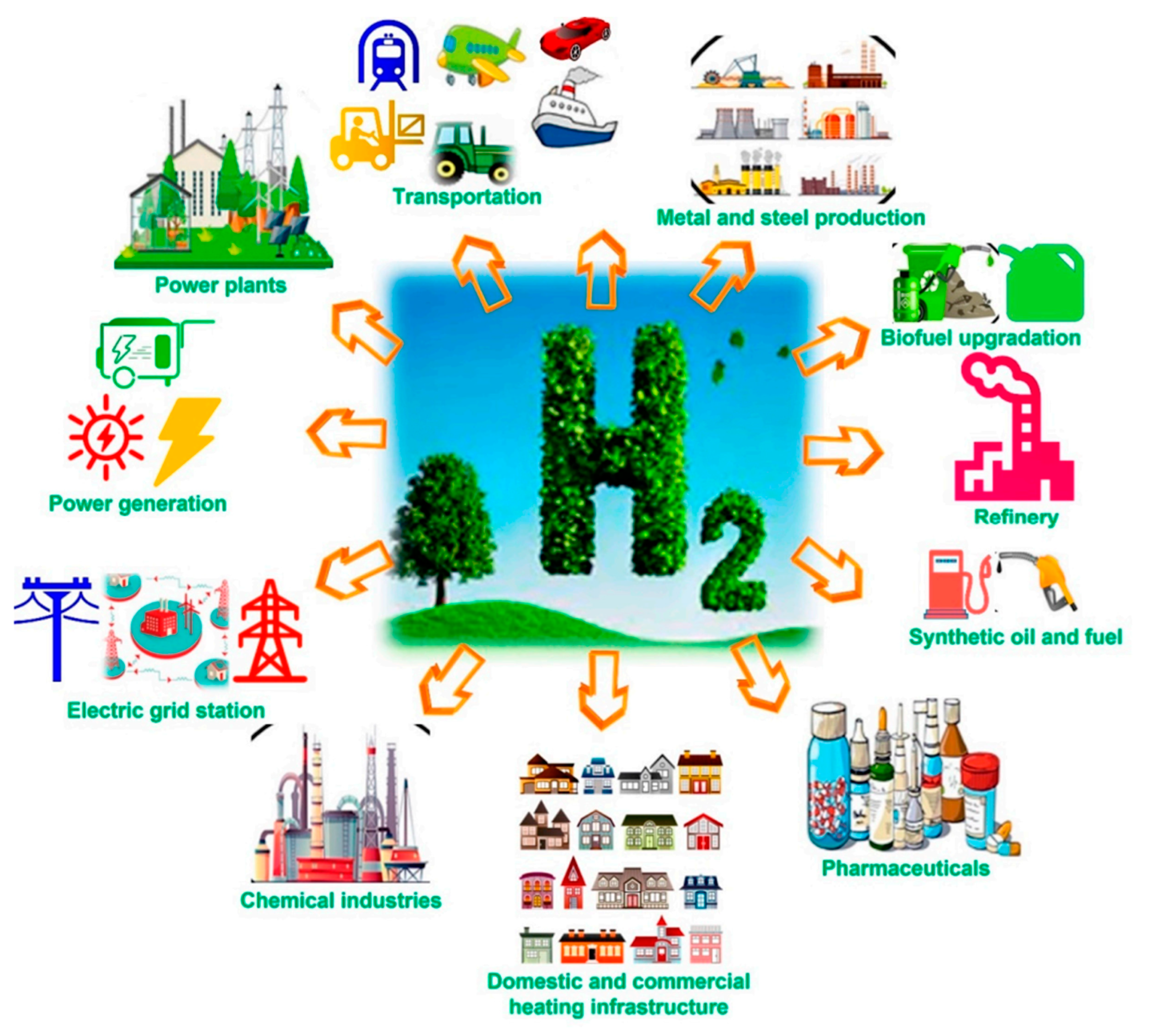
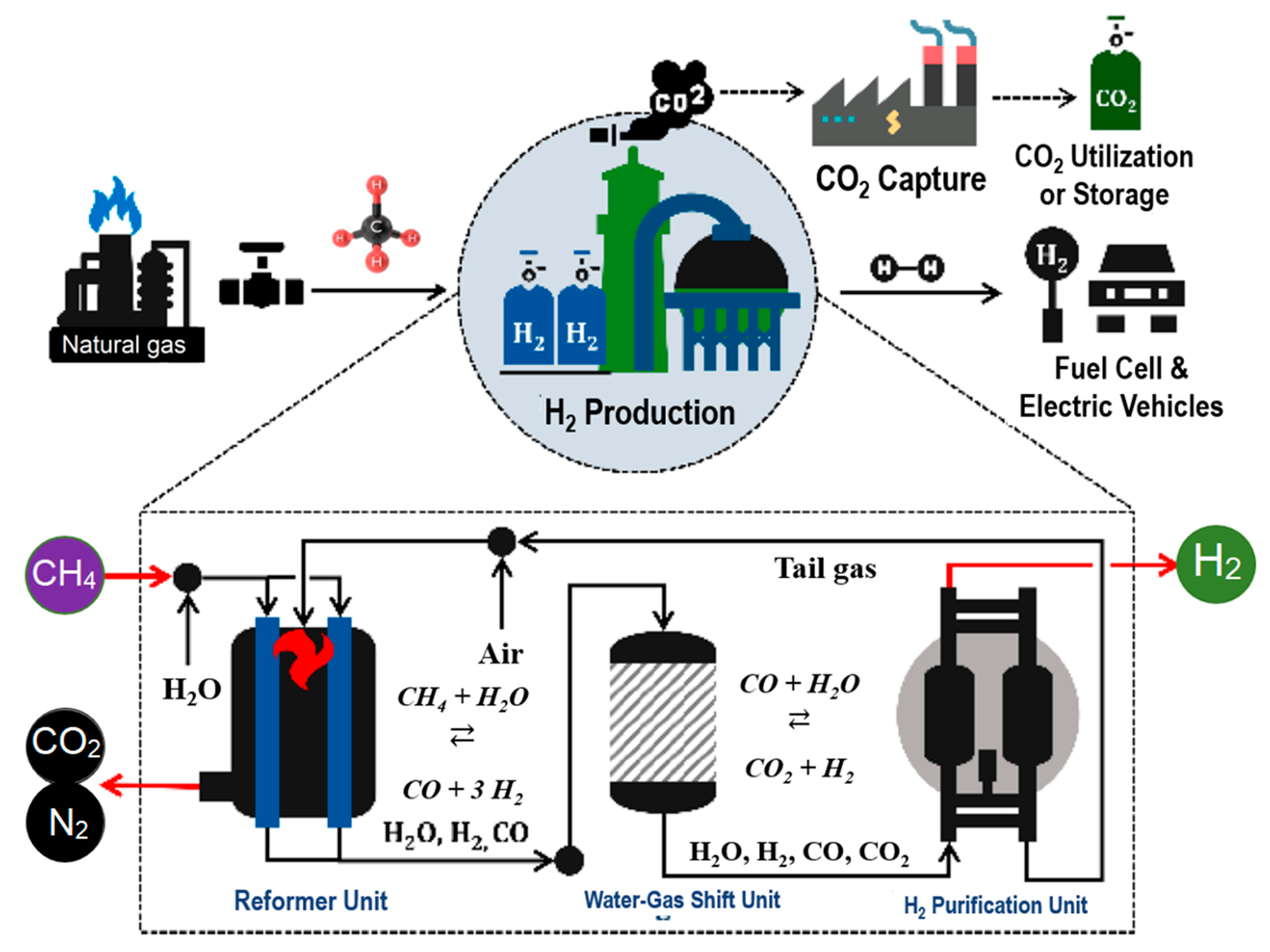
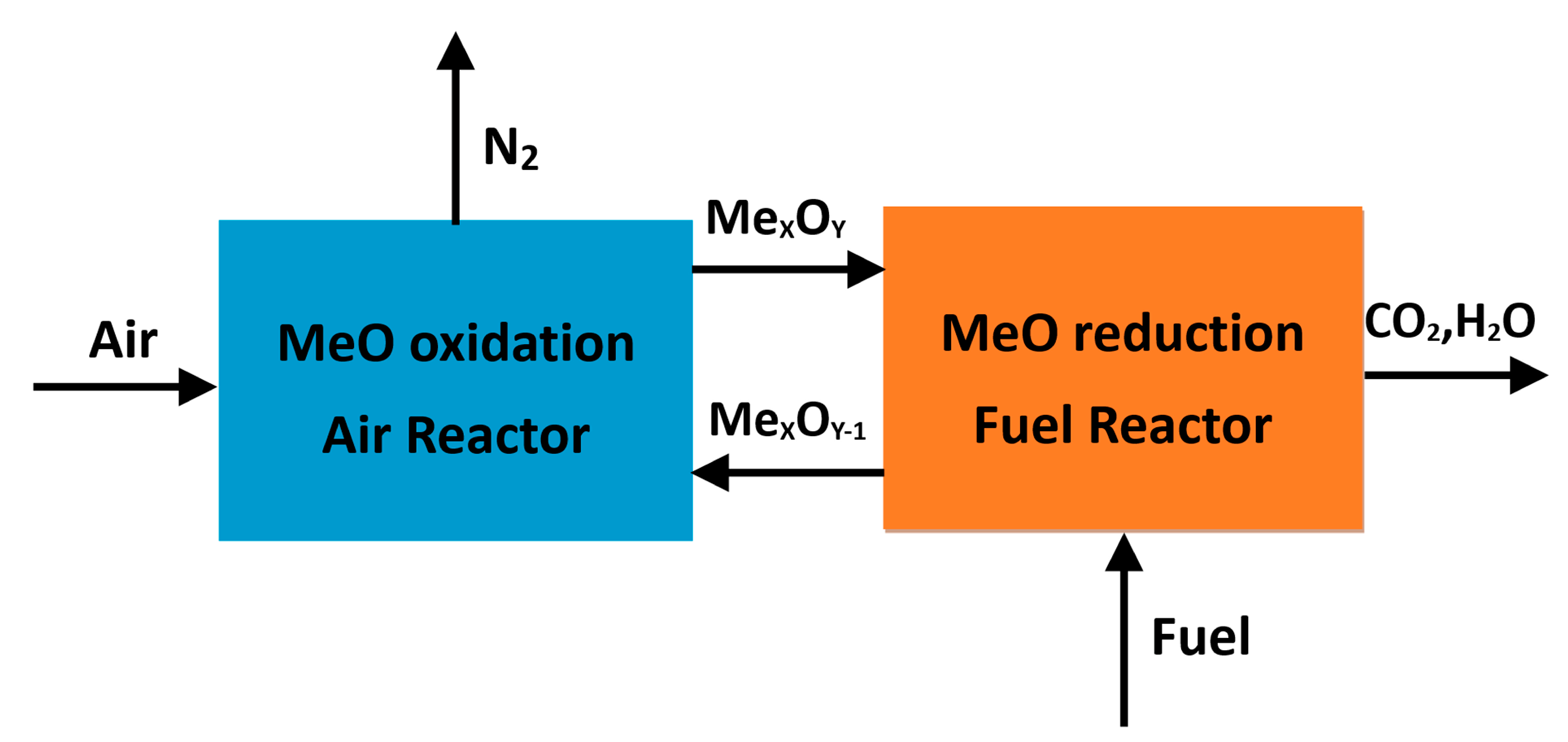
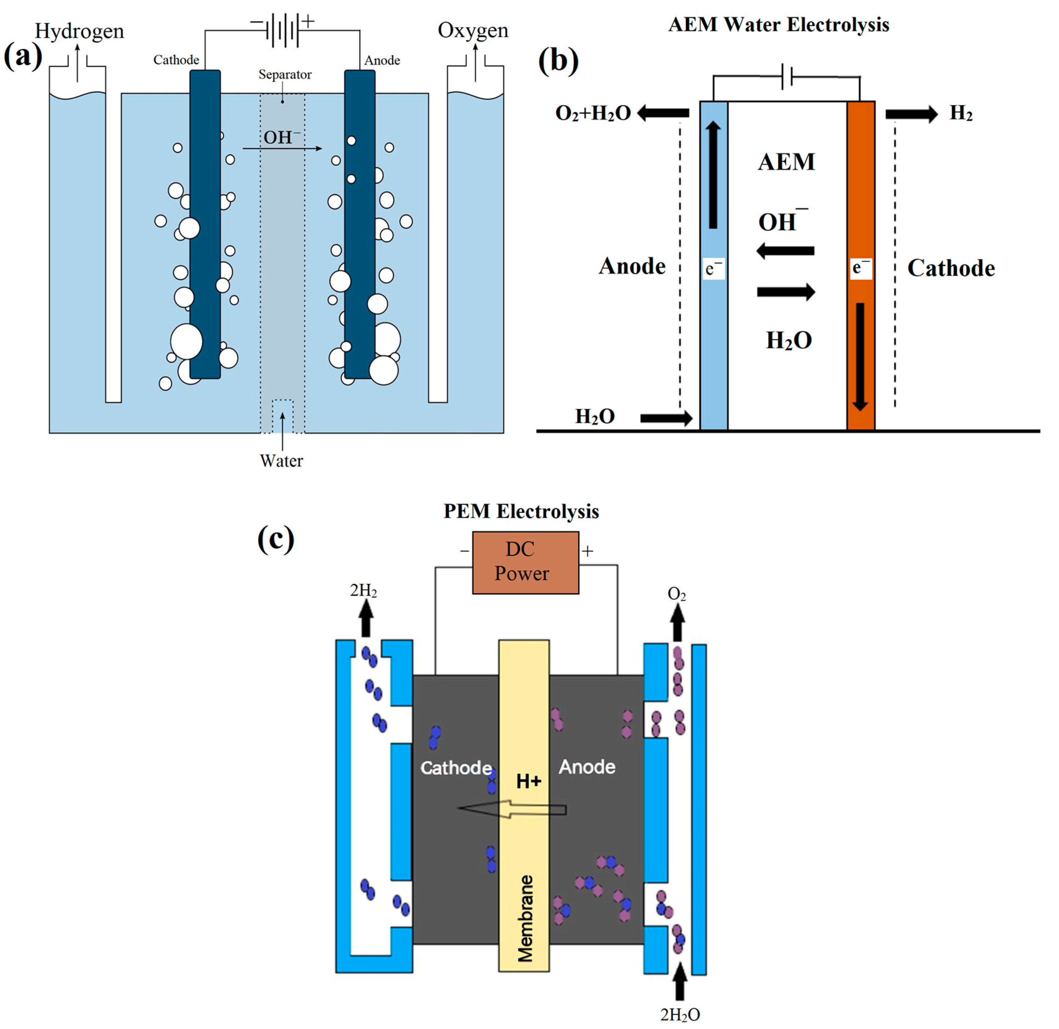
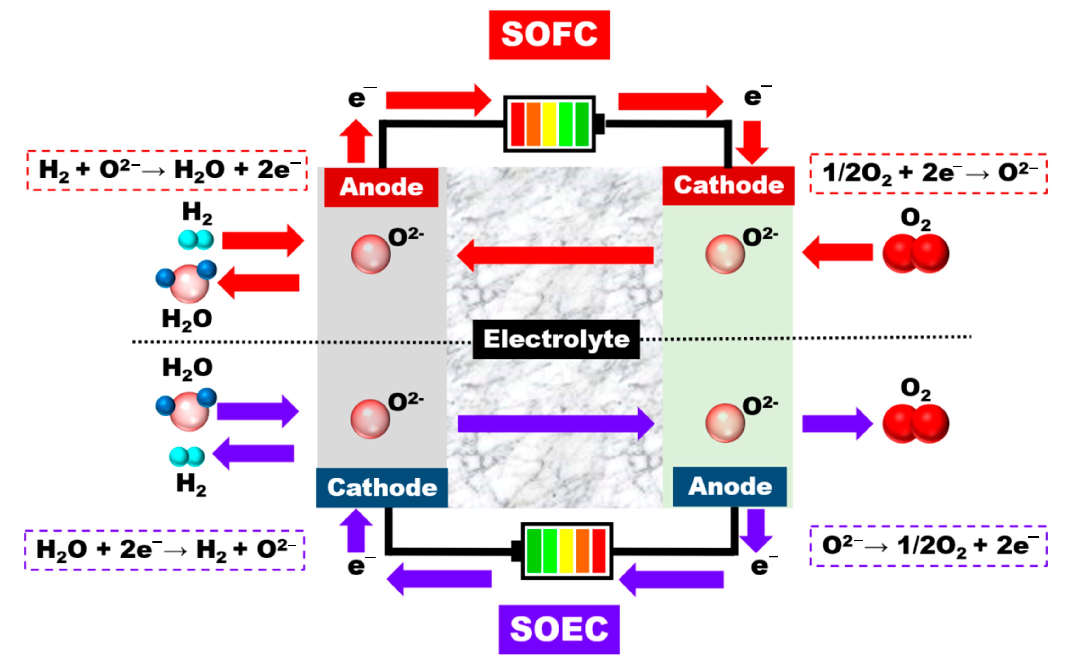
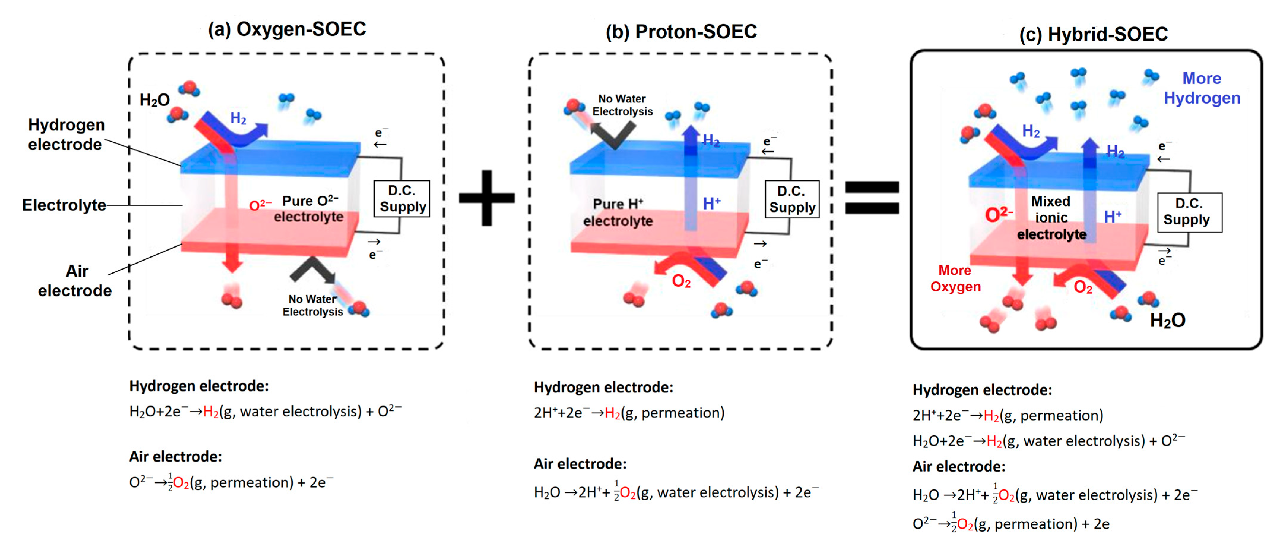
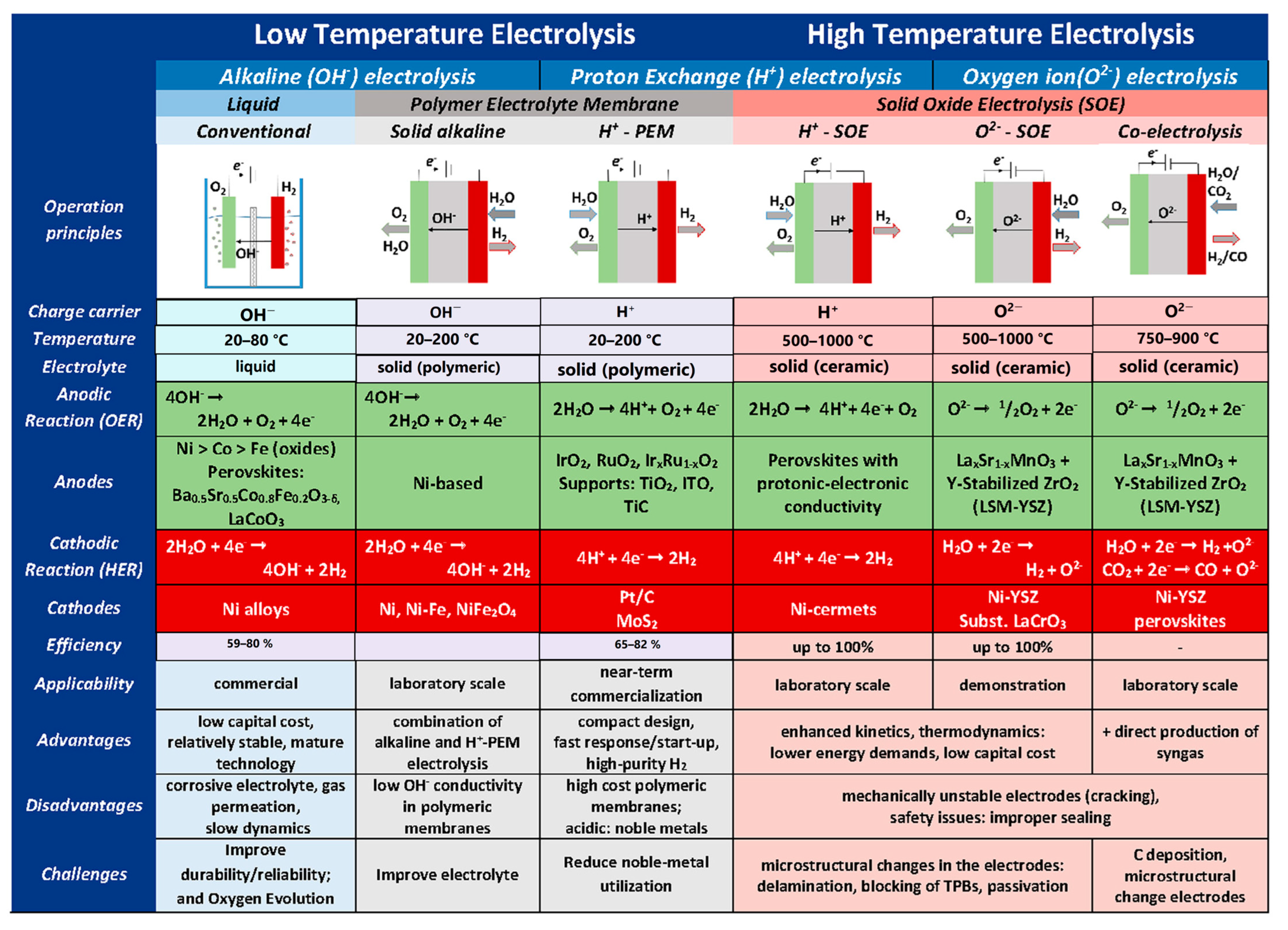
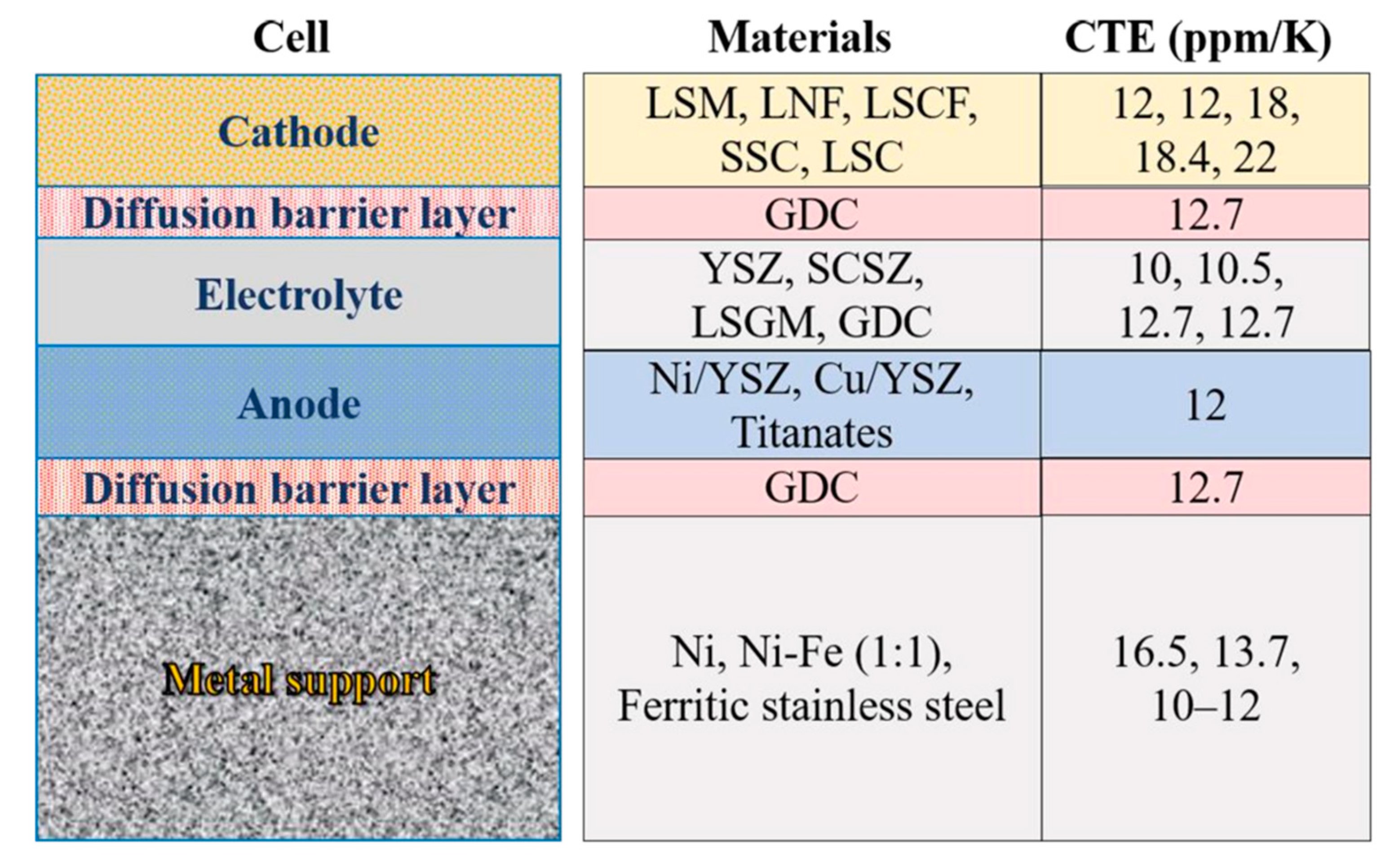
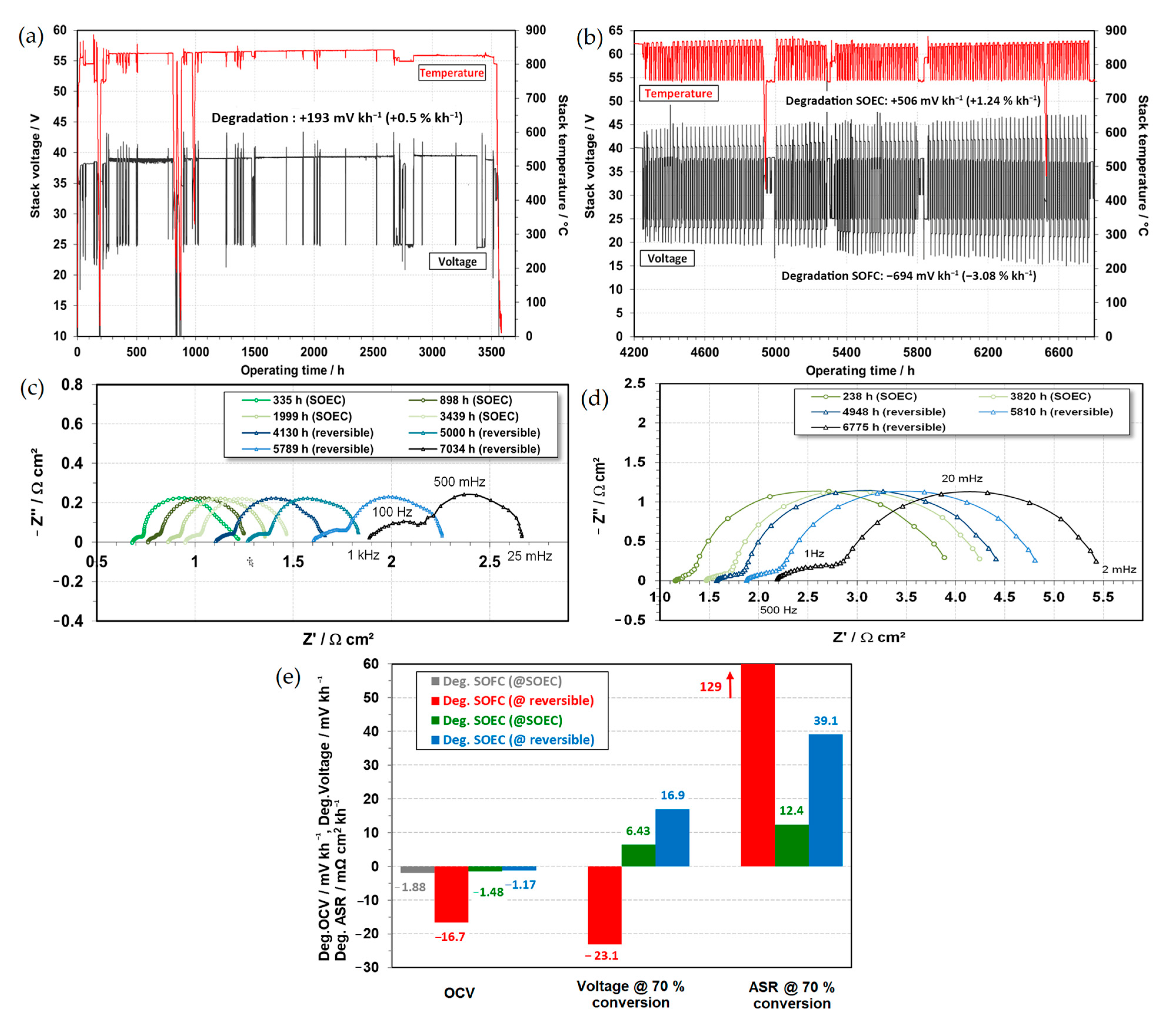
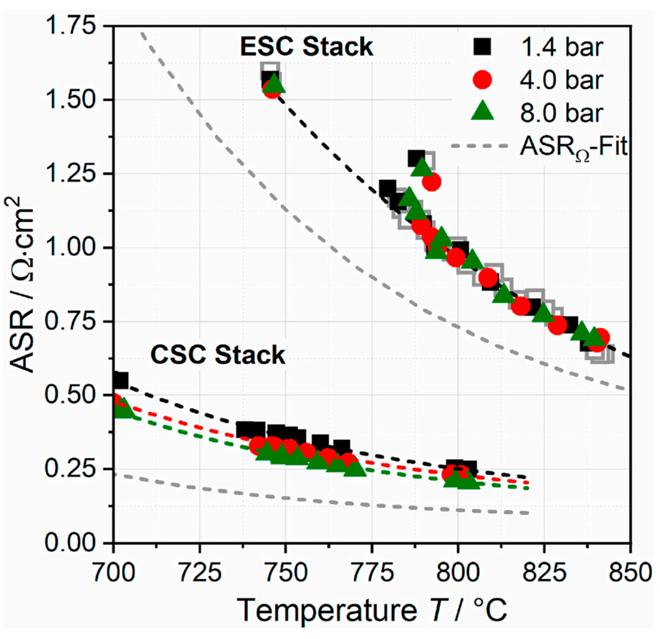
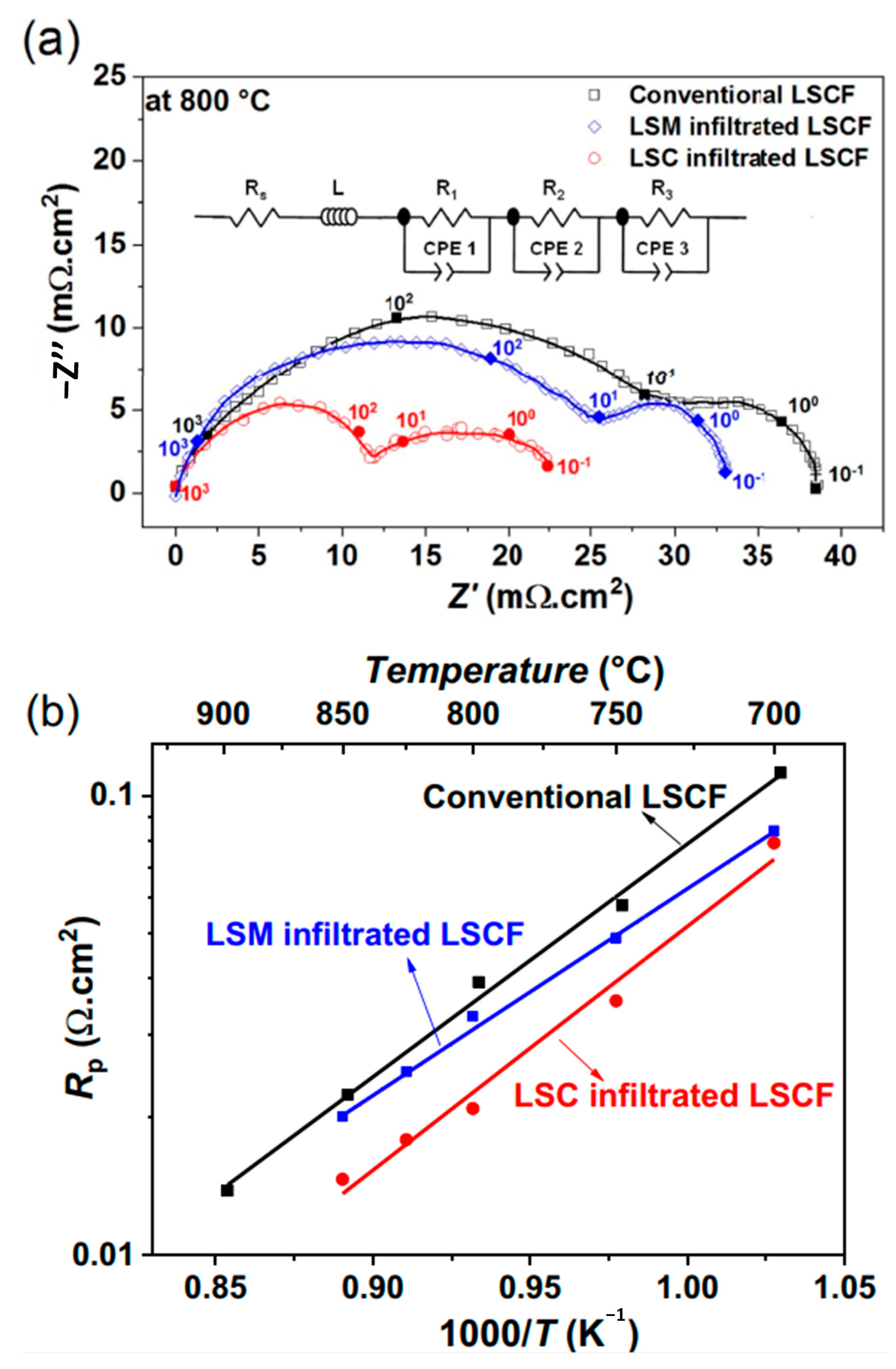
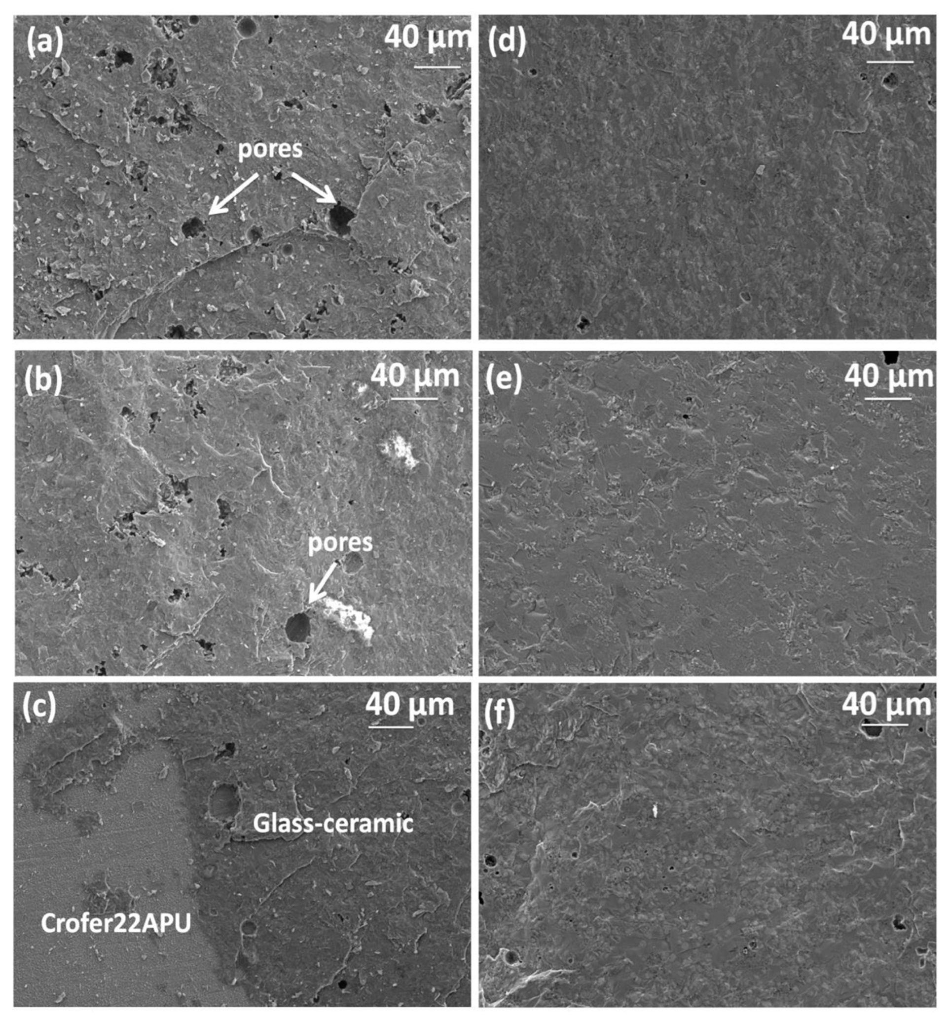
Table 1.
Energy content of several fuels [14].
Table 1.
Energy content of several fuels [14].
| Fuel | Energy Content (MJ.kg−1) |
|---|---|
| Hydrogen | 120 |
| Liquefied Natural Gas (LNG) | 54.4 |
| Propane | 49.6 |
| Gasoline | 45.6–46.8 |
| Ethanol | 29.6 |
| Methanol | 19.7 |
| Coke | 27 |
| Dry wood | 16.2 |
| Bagasse | 9.6 |
Table 2.
General properties of some of the most important hydrogen production technologies [66,69] (Reproduced with permission form [69], Elsevier: 2020).
| Process | Feedstock | Operating Condition | Level of Development | Efficiency (%) |
|---|---|---|---|---|
| Steam reforming | Light hydrocarbons | 700–1000 °C | Commercial | 74–85 |
| Partial oxidation | Hydrocarbons, coal, and heavy fuel oil | 800–1000 °C | Commercial | 60–75 |
| Autothermal refining | Light hydrocarbons | 700–1000 °C | Early commercial | 60–75 |
| Pyrolysis | Hydrocarbons | 1000–1400 °C | Commercial | 35–50 |
| Coal gasification | Coal | 700–1200 °C | Commercial | - |
| Ammonia reforming | Ammonia | 800–900 °C | Early commercial | 28 |
| Biomass gasification | Biomass | 800–1000 °C | Commercial | 30–60 |
| Thermolysis | - | >2500 °C (1000 °C < for thermochemical cycles) | R&D | 20–50 |
| Photoelectrolysis | Water and sunlight | Ambient conditions | R&D | 0.06–14 |
| Biophotolysis of microorganisms | - | Ambient conditions | R&D | 10–15 |
| Dark fermentation of | Carbohydrate-rich substrates | Anoxic conditions | R&D | 60–80 |
| Photofermentative | Small organic molecules and sunlight | Anaerobic conditions at ambient temperature | R&D | 0.1–12 |
| Pyrolysis of biomass | Biomass | 300–1000 °C (under an oxygen-free atmosphere) | Commercial | 21.9–75 |
| Alkaline electrolysis | Water and electricity | 40–90 °C | Commercial | 62–82 |
| PEM electrolysis | Water and electricity | 20–100 °C | Commercial | 67–82 |
| SOEC | Water, electricity, and heat | 700–1000 °C | R&D | ~100 |
| Hydrothermal liquefaction | Wet biomass | 4–22 MPa 250–370 °C | R&D | 85–90 |
| Thermochemical water splitting | Heat and water | 500–1000 °C | R&D | 20–45 |
Table 3.
Main benefits and drawbacks of common solid oxide cell geometries [2].
Table 3.
Main benefits and drawbacks of common solid oxide cell geometries [2].
| Cell Geometry | Strength | Weakness |
|---|---|---|
| Anode-supported |
|
|
| Electrolyte-supported |
|
|
| Cathode-supported |
|
|
| Metal-supported |
|
|
Table 4.
Material degradation in SOEC components [183] (Reproduced with permission from [183], IOP: 2016).
| Region | Degradation | Test Conditions |
|---|---|---|
| Physical, chemical, and microstructure change | ||
| LSM-YSZ//YSZ | LSM-YSZ: formation of small YSZ grains; YSZ: intergranular fracture and hole/pore formation along the grain boundaries of YSZ close to the air electrode. | 1–2 A.cm−2, 850 °C, 50%H2O/50%H2, 80–900 h |
| LSM//YSZ | LSM: delamination, disintegration of LSM particles at the interface; YSZ: grain boundary widening. | 500 mA.cm−2, 800 °C, 48 h. 895 °C |
| LSM-YSZ//YSZ | YSZ: void formation; no phase change; LSM-YSZ: delamination but no cation diffusion. | 895 °C up to 2.5 A.cm−2, 70% H2O |
| LSM-YSZ//YSZ | LSM: delamination, disintegration of LSM particles at the interface; YSZ: surface roughening. | 500 mA.cm−2, 800 °C, 100 h |
| LSM-YSZ//YSZ | LSM-YSZ: delamination. | 0.5 A.cm−2, 750 °C, 640 h |
| LSM-YSZ//YSZ | LSM-YSZ: La2Zr2O7 formation | 1.5–1.7 V, 800–950 °C |
| LSCF//YSZ | Delamination | 800 mA.cm−2, 800 °C, 50 h |
| LSCF/GDC//YSZ | LSCF: phase change from rhombohedral to cubic; GDC interlayer: pore formation | 800 mA.cm−2, 800 °C, 100 h |
| LSCF/GDC//YSZ | LSCF: SrZrO3 formation within GDC layer | As prepared |
| LSCF/GDC//YSZ | LSCF: SrZrO3 formation within GDC layer; YSZ: pore formation near the interface; GDC: Y and Zr diffusion into GDC interlayer, forming a dense reaction layer. | 0.75–1.0 A.cm−2, 780 °C, 9000 h. |
| LSCF/GDC//YSZ | LSCF: reduction of Co4+ to Co3+; GDC: Sr enrichment. | 0.8 A.cm−2 for 1000 h |
| LSCF-GDC/GDC//YSZ | LSCF-GDC: no delamination. | 0.5 A.cm−2, 750 °C, 640 h |
| LSC-GDC/GDC//YSZ | LSC-GDC: delamination at air inlet. | 0.5 A.cm−2, 750 °C, 640 h |
| Ni-YSZ//YSZ | Ni-YSZ: agglomeration of Ni particles, no change in YSZ phase. | 0.8 A.cm−2, 800 °C, 90%H2O/10%H2, 1000 h |
| Ni-YSZ//YSZ | Ni-YSZ: 2–4 μm dense Ni/YSZ layer | 2 A.cm−2, 950 °C, 90%H2O |
| Ni-YSZ//YSZ | Ni-YSZ: Ni agglomeration and depletion at the interface; YSZ: pore formation at the interface | 0.75–1.0 Acm−2, 780 °C, 80%H2O, 9000 h. |
| //10Sc1CeSZ | 10Sc1CeSZ: presence of Ce3+, phase change from cubic to rhombohedral | over 2 V. |
| Effect of Contaminants/Impurities | ||
| Ni-YSZ (porosity: 25%)//YSZ | Ni-YSZ: formation of carbon nano-fibre in Ni-YSZ electrode close to YSZ; Delamination | 2.25 A.cm−2, 875 °C, 45%H2O/45%CO2/10%H2, 11 h |
| Ni-YSZ (porosity: 40%)//YSZ | Ni-YSZ: No carbon deposition in Ni-YSZ electrode at the interface; No delamination | 2.0 A.cm−2, 875 °C, 45%H2O/45%CO2/10%H2, 677 h |
| Ni-infiltrated GDC//YSZ Ni-YSZ//YSZ: | Ni-YSZ: carbon deposition | 0.1 A.cm−2, 600 °C, 5%CO/95%CO2, 5 h |
| Ni-YSZ//YSZ: glass | Ni-YSZ: SiO2 deposition at region close to YSZ electrolyte. | 0.5 A.cm−2, 850 °C in 50%H2O/50%H2 for 1316 h |
| LSM//YSZ: Fe-Cr alloy | LSM: Cr deposition and SrCrO4 formation at the interface and in the electrode bulk. | 0.2–0.5 A.cm−2, 800 °C, air |
| LSCF//GDC: Fe-Cr alloy | LSCF: Cr deposition mainly on the outmost surface of the electrodes in the form of SrCrO4, CrO2.5, and Cr2O3 | 0.2 A.cm−2, 800–900 °C, air |
| LSC | LSC contact layer: Cr deposition mainly on the LSC contact layer. | 2000 h. |
| LSM//YSZ: glass | LSM: accelerated Sr segregation and boron deposition at the interface, forming lanthanum borates | 0.2 A.cm−2, 800 °C, air |
Table 5.
Common interconnect materials and their proposed coatings [137].
Table 5.
Common interconnect materials and their proposed coatings [137].
| Interconnect Material | Coating | Coating Technique | Test Conditions | ASR (mΩ) |
|---|---|---|---|---|
| SUS430 | Mn-Co | PVD | 800 °C/air/1250 h | 28.6 |
| AISI 430 | Mn-Co | DGPA | 800 °C/air | 29 (480 h) |
| Crofer22 APU | MnCo1.7Fe0.3O4 | EPD | 800 °C/air/1000 h | - |
| Crofer22 APU | MnCo1.7Fe0.3O4 | APS | 700 °C/air/1000 h | 50 |
| Sanergy HT | (Mn, Co)3O4 | Screen printing | 800 °C/air/1000 h | - |
Disclaimer/Publisher’s Note: The statements, opinions and data contained in all publications are solely those of the individual author(s) and contributor(s) and not of MDPI and/or the editor(s). MDPI and/or the editor(s) disclaim responsibility for any injury to people or property resulting from any ideas, methods, instructions or products referred to in the content. |
© 2023 by the authors. Licensee MDPI, Basel, Switzerland. This article is an open access article distributed under the terms and conditions of the Creative Commons Attribution (CC BY) license (https://creativecommons.org/licenses/by/4.0/).
Share and Cite
MDPI and ACS Style
Fallah Vostakola, M.; Ozcan, H.; El-Emam, R.S.; Amini Horri, B. Recent Advances in High-Temperature Steam Electrolysis with Solid Oxide Electrolysers for Green Hydrogen Production. Energies 2023, 16, 3327. https://doi.org/10.3390/en16083327
AMA Style
Fallah Vostakola M, Ozcan H, El-Emam RS, Amini Horri B. Recent Advances in High-Temperature Steam Electrolysis with Solid Oxide Electrolysers for Green Hydrogen Production. Energies. 2023; 16(8):3327. https://doi.org/10.3390/en16083327
Chicago/Turabian StyleFallah Vostakola, Mohsen, Hasan Ozcan, Rami S. El-Emam, and Bahman Amini Horri. 2023. "Recent Advances in High-Temperature Steam Electrolysis with Solid Oxide Electrolysers for Green Hydrogen Production" Energies 16, no. 8: 3327. https://doi.org/10.3390/en16083327
Note that from the first issue of 2016, this journal uses article numbers instead of page numbers. See further details here.