
Passive Hydrogen Recombination during a Beyond Design Basis Accident in a Fusion DEMO Plant
by
 , ,
, ,
Matteo D’Onorio
1,*,
Tommaso Glingler
1,
Guido Mazzini
2,
Maria Teresa Porfiri
3 and
Gianfranco Caruso
1 1
Department of Astronautical Electrical and Energy Engineering (DIAEE), Sapienza University of Rome, C.so Vittorio Emanuele II 244, 00186 Rome, Italy
2
Centrum Vyzkumu Rez (CVRez), Hlavní 130, Husinec, 250 68 Řež, Czech Republic
3
UTFUS-TECN, ENEA CR. Frascati, Via Enrico Fermi, 45, 00044 Frascati, Italy
*
Author to whom correspondence should be addressed.
Energies 2023, 16(6), 2569; https://doi.org/10.3390/en16062569
Submission received: 15 February 2023
/
Revised: 1 March 2023
/
Accepted: 6 March 2023
/
Published: 8 March 2023
(This article belongs to the Special Issue Water Coolant Lithium Lead Breeding Blanket and Test Blanket Module: Design and R&D Activities in 2022)
Abstract
:One of the most important environmental and safety concerns in nuclear fusion plants is the confinement of radioactive substances into the reactor buildings during both normal operations and accidental conditions. For this reason, hydrogen build-up and subsequent ignition must be avoided, since the pressure and energy generated may threaten the integrity of the confinement structures, causing the dispersion of radioactive and toxic products toward the public environment. Potentially dangerous sources of hydrogen are related to the exothermal oxidation reactions between steam and plasma-facing components or hot dust, which could occur during accidents such as the in-vessel loss of coolant or a wet bypass. The research of technical solutions to avoid the risk of a hydrogen explosion in large fusion power plants is still in progress. In the safety and environment work package of the EUROfusion consortium, activities are ongoing to study solutions to mitigate the hydrogen explosion risk. The main objective is to preclude the occurrence of flammable gas mixtures. One identified solution could deal with the installation of passive autocatalytic recombiners into the atmosphere of the vacuum vessel pressure suppression system tanks. A model to control the PARs recombination capacity as a function of thermal-hydraulic parameters of suppression tanks has been modeled in MELCOR. This paper aims to test the theoretical effectiveness of the PAR intervention during an in-vessel loss of coolant accident without the intervention of the decay heat removal system for the Water-Cooled LithiumLead concept of EU-DEMO.
1. Introduction
As well as for fission power plants, the main environmental and safety issue for fusion power devices is the control of the radioactive substances and their confinement into the reactor buildings. This is needed to prevent significant releases of radioactivity to the environment during both normal operations and accident conditions. For this purpose, fusion power plants’ safety studies have highlighted that hydrogen accumulation and the subsequent combustion must be avoided. The pressure and energy generated may threaten the integrity of the confinement structures, causing the dispersion of radioactive and toxic products toward the public environment [1,2,3,4,5].
In the fight against climate change, nuclear power plants can stand as a central asset in the baseload power generation, working together with renewable energies to satisfy the total consumption demand. Active NPPs installed around the globe are well-known technologies that provide 10% of the world’s electricity from about 440 power reactors [6,7]. The Light Water Reactor (LWR) is the most widespread technology adopted, divided mainly between Pressurized Water Reactors (PWRs) [8], and Boiling Water Reactors (BWRs) [9]. Another technology with several operative reactors is the Pressurized Heavy Water Reactor (PHWR) [10]. Innovative fission nuclear power plant designs based on the Small Modular Reactor (SMR) approach are being developed; the goal is to achieve an increased level of safety and reduce the amounts of nuclear waste produced [11]. At the same time, fusion power devices based on the tokamak concept aim to demonstrate an inherent safety concept and drastically reduce the volume of the radioactive waste produced in fission power plants [12].
The research of technical solutions to avoid the risk of a hydrogen explosion in large fusion power plants is still in progress. The first objective is to preclude the occurrence of flammable gas mixtures. If flammability limits are exceeded anywhere, the second objective is to avoid more dangerous concentrations.
Since the vacuum vessel (VV) represents the first confinement barrier to these radioactive materials, its integrity must be ensured during several accident scenarios. In the event of a postulated accident involving the ingress of steam into the VV, hydrogen could be produced by oxidation reactions between water/steam and Plasma-Facing Components (PFCs), hot dust (W and Be), or liquid metal [13,14,15]. Moreover, hydrogen isotopes are used as fuel in tokamak reactors. If the ingress of air into the VV is also postulated, the reaction of air with hydrogen and dust cannot be excluded entirely and could lead to a possible explosion, which could compromise the VVs integrity.
Proposed solutions to preclude the occurrence of flammable gas mixtures could deal with the injection of inert gas in the VV and vacuum vessel pressure suppression system (VVPSS) tanks or the installation of a hydrogen recombination system connected with the VVPSS. The disadvantage of injecting an inert gas is that hydrogen and tritium are not removed from the system but only diluted. Moreover, this solution is complex to realize because large tanks available for the inert gas storage, ducts for the gas injection, and active systems to trigger the intervention of the system are needed. For this reason, the safety and environment work package of the EUROfusion consortium is currently investigating the possibility of using a passive recombination system consisting of self-starting and self-feeding autocatalytic recombiners that trigger spontaneously as soon as the hydrogen concentration begins to increase in the atmosphere. In tokamak devices, recombiners could be installed inside the VVPSS suppression tanks (STs) or in suitable expansion tanks (ETs) to deal with the possible concentration of hydrogen in the free volume atmosphere.
Several experimental programs have been established to study the behavior of Passive Autocatalytic Recombiners (PARs) under different conditions. In particular, the THAI experimental program was one of the most comprehensive test series that was performed using several different PARs manufactured worldwide [16,17]. Experience gained in the THAI test campaign highlighted that PAR systems are designed to work in the pressure range of 0.9–3 bar. Moreover, the efficiency of the hydrogen recombination system depends on the local atmosphere composition in the recombiner box and on their location.
Past studies, reported in [1], have highlighted that because of differences in the operative pressure between the fission and fusion applications, the Fisher-based model implemented in MELCOR fusion code [18,19] could overestimate the mass of the hydrogen recombined by PARs. To better evaluate the effectiveness of PAR recombiners installed in VVPSS suppression tanks, a new model has been developed in MELCOR. In particular, this custom model can assess the mass of hydrogen recombined, considering the operating pressure and mole fractions of the atmosphere surrounding the PAR.
The postulated initiating event (PIE) chosen to study the theoretical effectiveness of the recombination system is an in-vessel loss of coolant accident, from the Primary Heat Transfer System (PHTS) [13]. The recombination system has been modeled with two different approaches. In the first model, the PAR units are installed in two suppression tanks; while in the second approach, the suppression tanks have been initialized in saturated conditions, and the PAR units are installed in suitable expansion tanks. The results demonstrated that the first solution allows the recombination of a large part of the mobilizable hydrogen until the atmosphere reaches a high hydrogen concentration, posing serious safety concerns. The second solution demonstrated the recombination of a large part of the mobilizable hydrogen, which is more effective in explosion risk mitigation.
The remainder of the paper is organized as follows. Section 2 of the Material and Methods presents the DEMO reference design adopted for this analysis. Since MELCOR has been adopted as the system code to analyze the LOCA transient, Section 2.1 describes the MELCOR model of the EU-DEMO design. The results are presented in Section 3, where two different approaches are compared. The first approach in Section 3.1.1 simulates hydrogen recombination with PAR installed in two different suppression tanks; while in Section 3.1.2, the PARs are installed in two expansion tanks that are connected through bleeding lines to the suppression tanks.
2. Materials and Methods
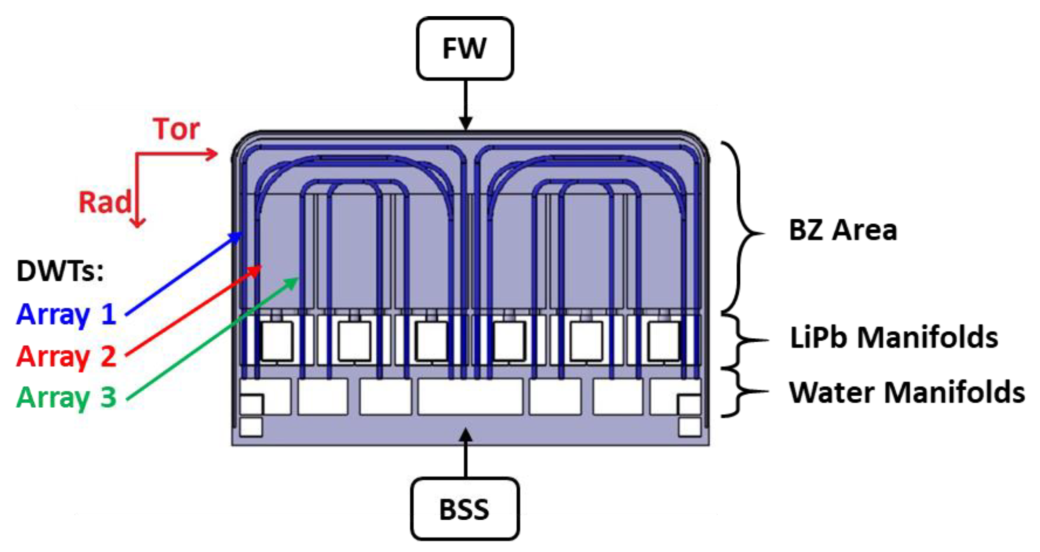
The study adopted the reference design of the European DEMOnstratation (EU-DEMO) [20] with a fusion power equal to 1923 MWth. The blanket component, which is one of the candidate options, is based on the Water-Cooled LithiumLead (WCLL) concept [21]. The blanket is characterized in the toroidal direction by 16 sections. The design of each sector is based on an OutBoard blanket (OB), which includes three segments, and an InBoard (IB) blanket, which is made up of two segments. A total of 100 breeding cells are contained in each single segment and are distributed along the poloidal direction. The WCLL 2018 V0.6 is the reference equatorial breeding cell of the central OB adopted for the model, shown in Figure 1 and described in detail in [22]. The First Wall (FW) is included in the front element of the Breeding Zone (BZ). The layer of the FW facing the plasma chamber is made of 2 mm thickness of tungsten, and a second layer of 25 mm thickness of EUROFER. The module and the FW are cooled by integrated C-shaped squared channels of 7 × 7 mm and a pitch of 13.5 mm. Two independent cooling systems are adopted for the FW and the BZ. Violent chemical reaction between the breeder and the cooling water represents a risk in case of a pipe rupture [22]. The approach to minimize the risk associated with an in-board tube rupture is based on the radial-toroidal Double Walled Tubes (DWTs) disposition of the BZ coolant pipes. The DWT component consists of two horizontal sections in the toroidal direction, each section is made up of 3 tube arrays in the radial direction. Thermo-dynamic conditions of cooling water are 295–328 °C and 15.5 MPa.
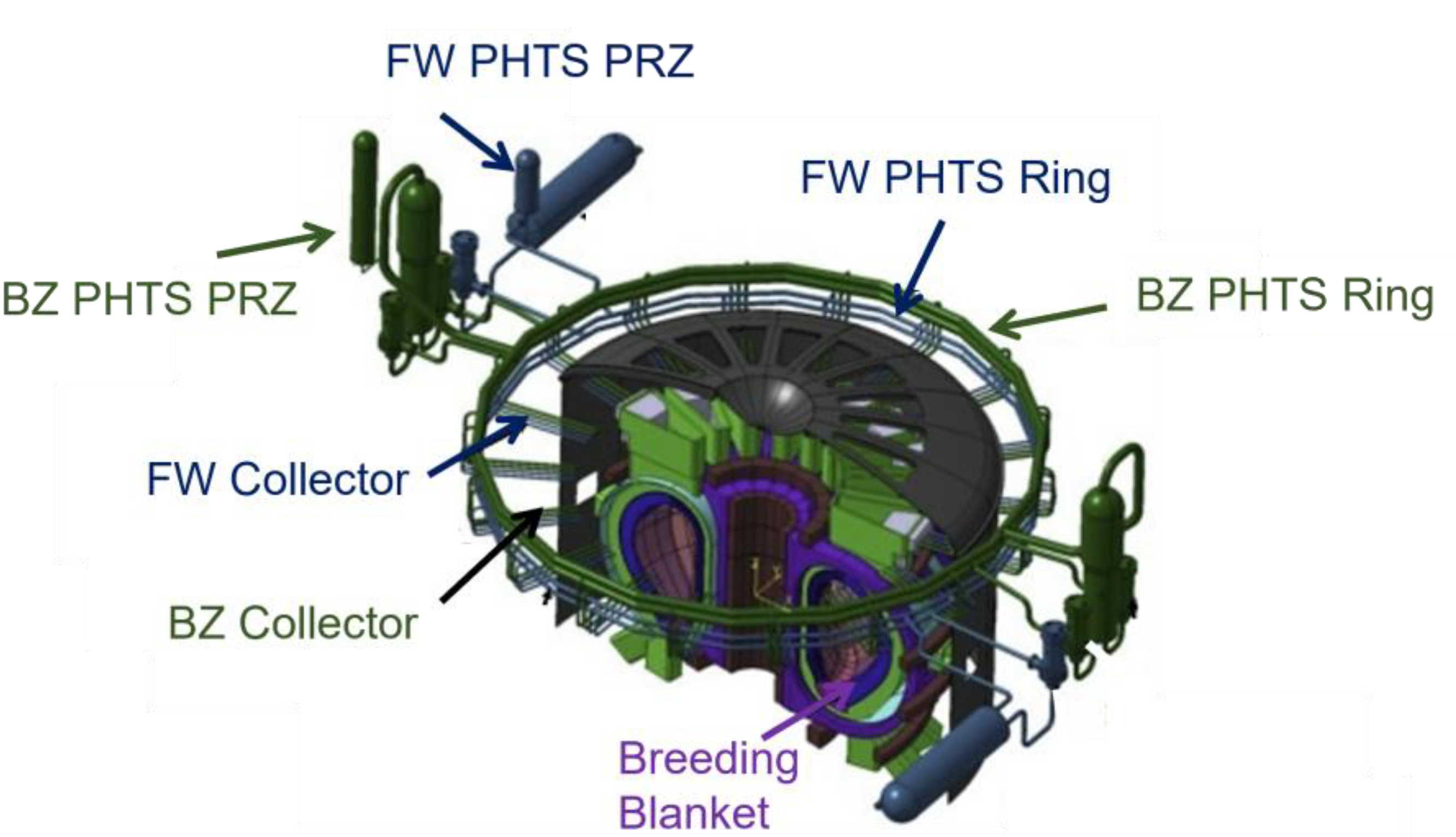
The pipework of the BZ and FW cooling continues outside of the VV collected by the corresponding blanket manifold; through feeding pipes hosted in VV, the upper port compartment, the manifolds are connected to the upper part of the Primary Heat Transfer System (PHTS), which is located outside the Bioshield. All the components that are placed outside the VV are shown in Figure 2 (e.g., sector manifolds, pressurizer, pumps, the BZ once-through steam generators, the hot and cold distributor rings, and the FW heat exchangers). The complete description of the PHTS design is provided in [23,24].
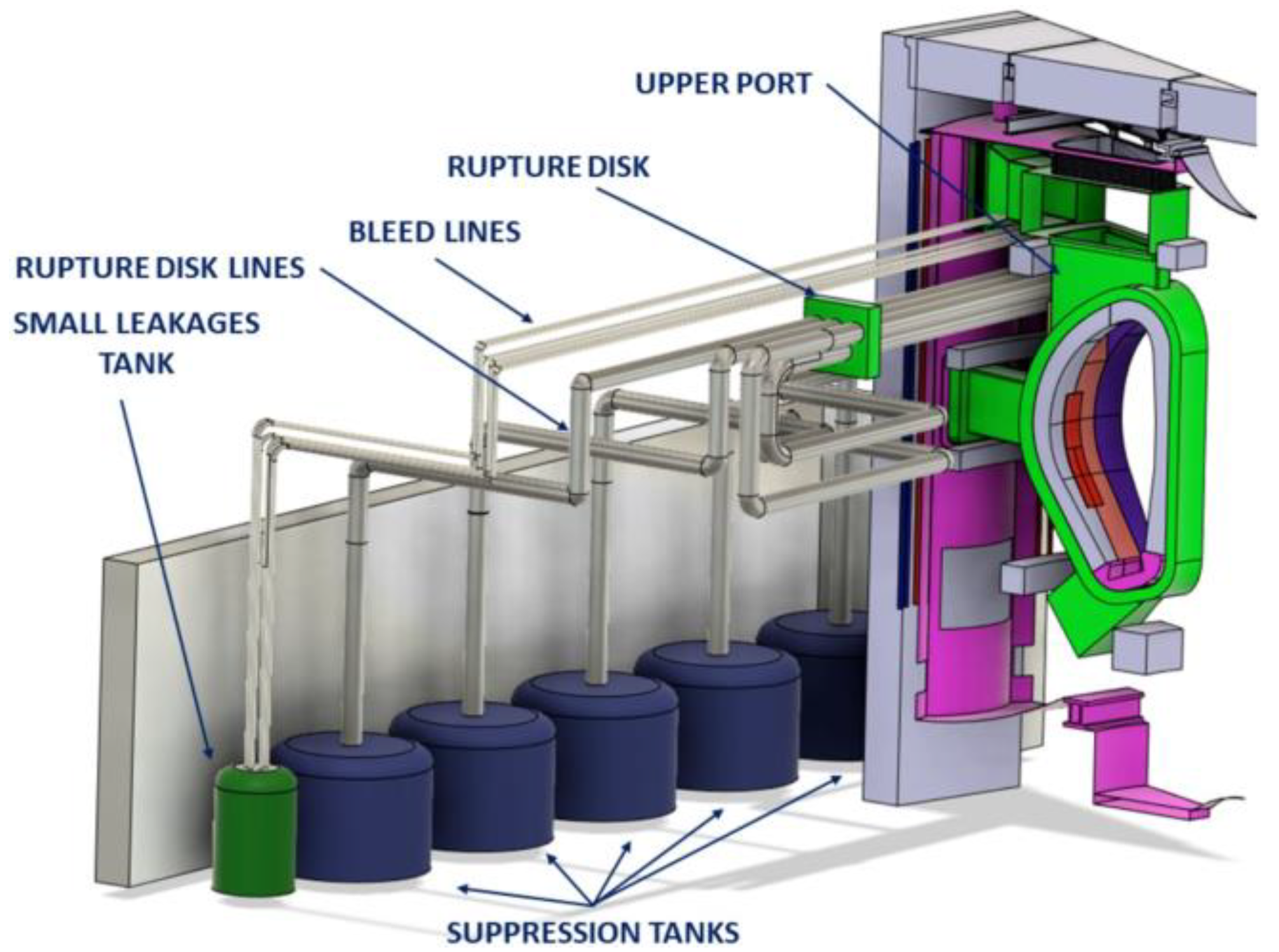
In case of in-vessel LOCA, the most important safety system designed to maintain the critical safety function is the VV pressure suppression system (VVPSS). The VVPSS, classified as a SIC-1 system [25], is designed to limit the pressure peak under the allowable value of the VV and to confine the radioactive sources. The current design of the VVPSS includes six separate suppression pools, one of which is dedicated to handle small leakages as shown in Figure 3. The tanks and the associated pipework are located in the containment basements. The pipework consists of 6 bleed lines (BLs) connecting the upper part of the VV to the small leakage tank, while five rupture disk (RD) lines are dedicated to the remaining suppression tanks. The small leakage tank has a volume equal to 300 m3, of which 180 m3 are filled with water; the remaining tanks have a higher volume of 500 m3, which are filled with 300 m3 of water. The thermal-hydraulic state inside of the tanks is set at 9.5 kPa with the liquid water pool at 40 °C. The BLs and RD lines are equipped with customed bleed valves and rupture disks, respectively. The setpoint of the bleed valves is set at 90 kPa, while the rupture discs setpoint is set at 150 kPa.
2.1. MELCOR Modeling
The fully integrated, engineering-level thermal hydraulics analysis code, MELCOR fusion (v. 1.86), has been used to study the possibility of hydrogen recombination in EU-DEMO during the selected accident scenario.
MELCOR [18] is a fully integrated severe accident code that simulates thermal-hydraulic and the main severe accident phenomena in steady or transient conditions concerning the components of LWRs. MELCOR is validated to analyze transport and estimation of source term; therefore, it is adopted as a tool for evaluating probabilistic risk assessment for second-generation nuclear power plants. The code is developed at Sandia Laboratories for the U.S. Nuclear Regulatory Commission. The structure of the system code has a modular structure based on control volume (CV) approach. The transient phenomenology is simulated by each of the MELCOR packages. In particular, the control volume hydrodynamics (CVH) and flow path (FL) packages estimate the mass and energy transfer between control volumes, while the Heat Structure (HS) package evaluates the thermal response of the HSs.
In the Fusion Safety Program, the Idaho National Laboratory made modifications to the MELCOR code fusion specific applications. New numerical models were included to evaluate flow boiling in coolant loops, carbon, beryllium, and tungsten oxidation in steam and air environments, water freezing, radiative heat transfer in enclosures, and air condensation [19]. These modifications allowed MELCOR to assess the thermal-hydraulic response of DEMO fusion reactor cooling systems and the transport of radionuclides as aerosols during accident conditions.
2.1.1. PHTS Nodalization
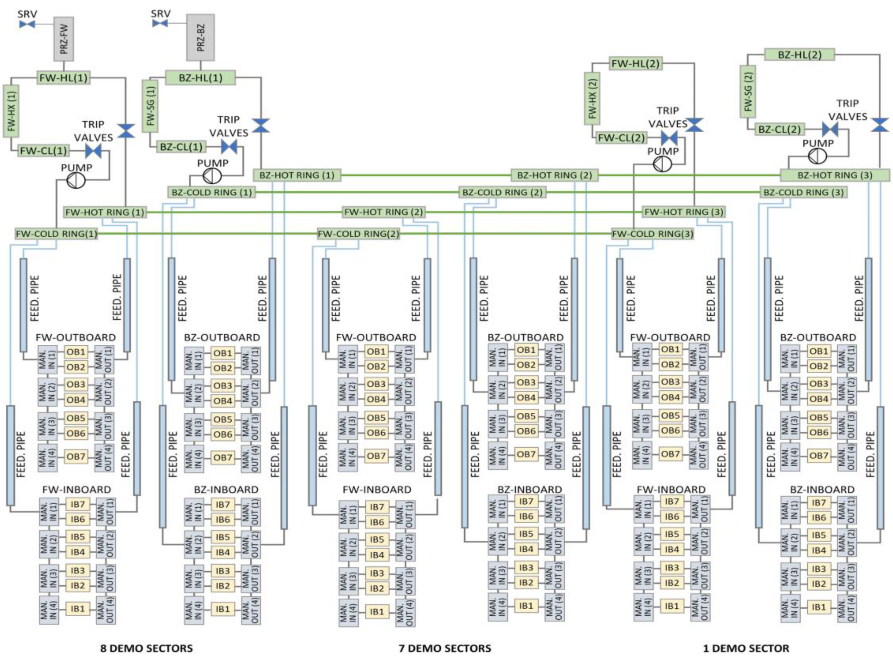
The sixteen toroidal sectors of the breeding blanket (BB) have been modeled in three groups. The first group consist of one sector, the second simulate seven sectors (starting from sector two to sector eight), while the third group consists of eight sectors (starting from sector nine to sector sixteen). The data for the PHTS model have been taken from [26], and the components have been modeled in MELCOR in one-dimensional units.
2.1.2. Vacuum Vessel Nodalization
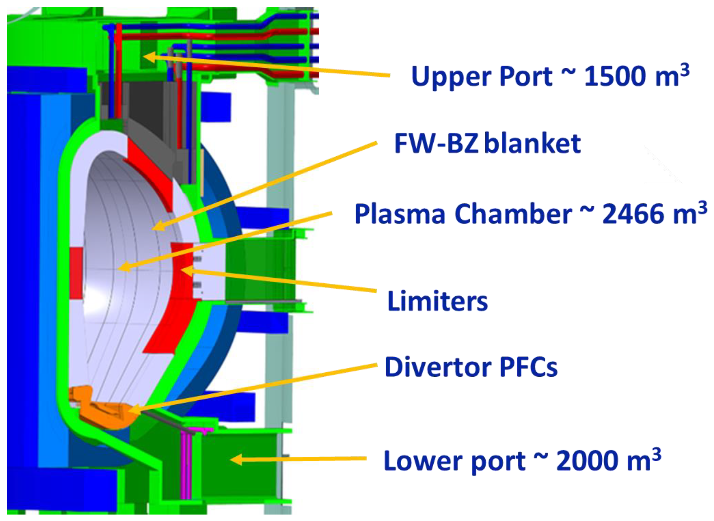
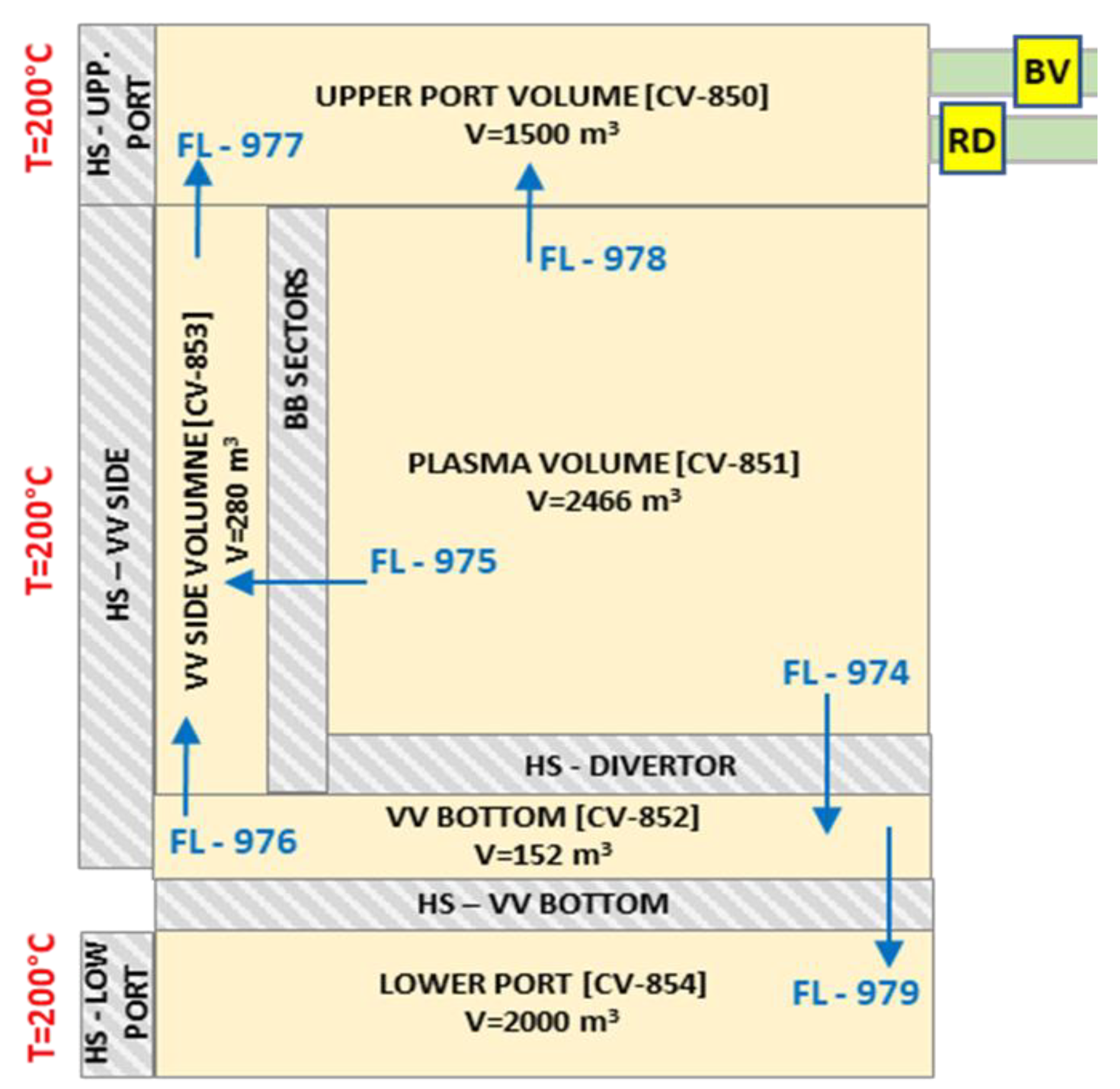
The VV model consist of five control volumes, each one simulating a different environment. Starting from the bottom, the lower port is modeled with the CV854 of 2000 m3. Moving upwards, the CV852 models the interspace between the divertor and the VV structure. The plasma chamber is the CV851 of 2466 m3; the CV853 of 280 m3 simulates the interspace between the Back-Supporting Structure (BSS) of BB modules and VV. The upper port volume of the VV is modeled with the CV850 with a total volume equal to 1500 m3. The authors of [27] provide additional details of the VV nodalization scheme. Figure 5 shows the CAD model of the EU-DEMO VV while Figure 6 shows the MELCOR nodalization of the VV.
2.1.3. Vacuum Vessel Pressure Suppression System
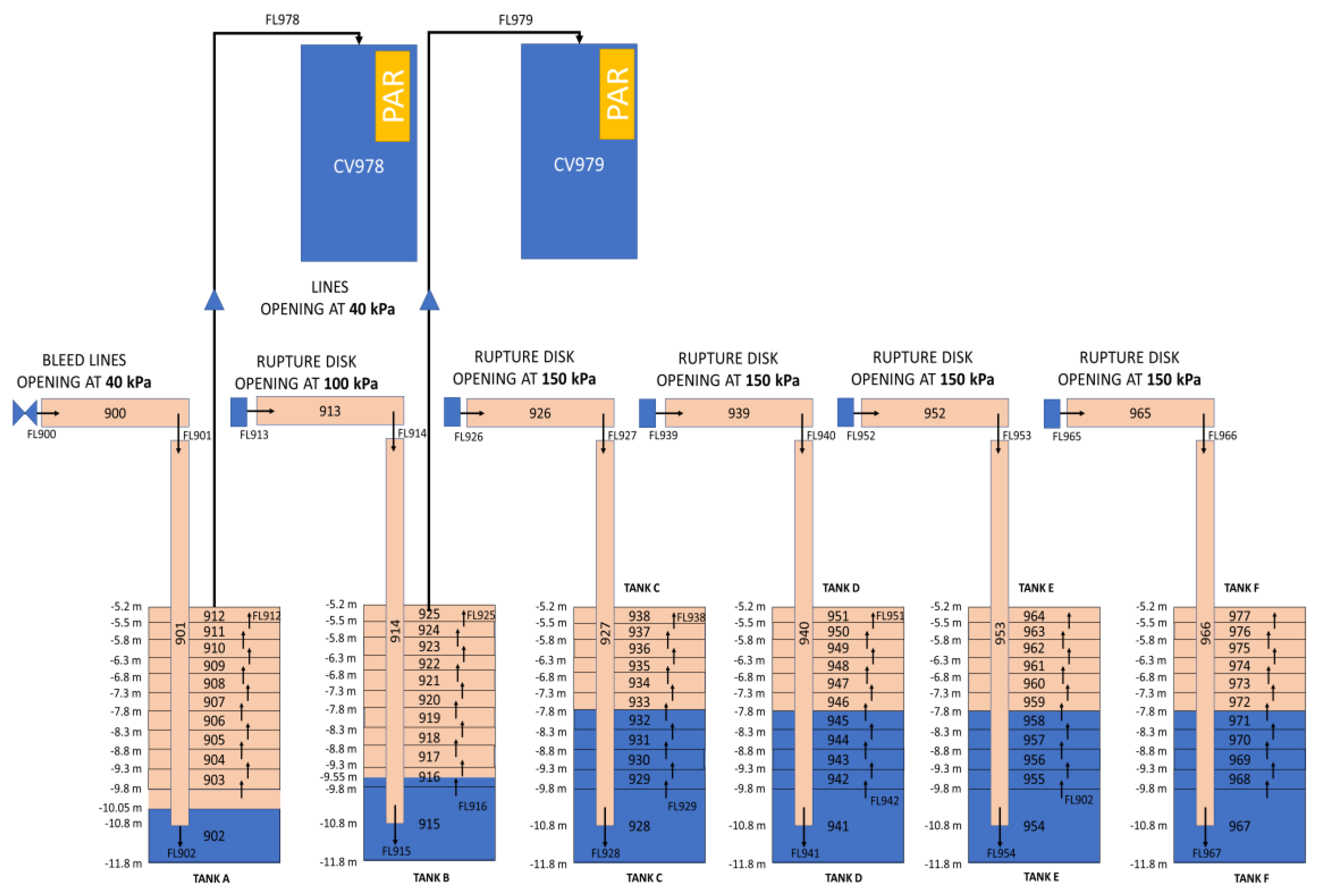
The developed model for the VVPSS consists of 84 CVs and connecting FLs. Each tank has been modeled separately with 12 CVs and the associated rupture disks or bleed lines (BLs). The discharging flow areas have been obtained from [29]. Each bleed line has a flow area of 0.1 m2, for a total flow area available for discharging steam in tank A of 0.6 m2; while each rupture disk line has a flow area of 1.6 m2, for a total flow area available for discharging steam in tank B to F of 8.0 m2.
As specified before, considering the last VVPSS design, the setpoints for the triggering of discharge lines from VV toward VVPSS are 90 kPa and 150 kPa for BL and RD lines, respectively. Tank A has a volume of 300 m3 and contains 180.0 m3 of subcooled water (40 °C at 9.5 kPa). Each RD tank has a volume of 500 m3 filled with 300 m3 of subcooled water. The current design has been used to perform a preliminary simulation. However, some modifications have been made to the VVPSS design to avoid the risk of a hydrogen explosion and to improve the effectiveness of the passive recombiner system. The solution consists of varying the opening setpoint of BLs and RDs, as well as the water level inside tank A and tank B suppression tanks. Moreover, two ETs, where part of the hydrogen is collected and recombined, have been added to the system.
The nodalization scheme of the proposed VVPSS concept is shown in Figure 7.
In addition to the introduction of ETs, the main differences with the current design of the suppression system are as follows:
- The opening setpoint of bleed lines and RDs to tank B have been reduced to 40 kPa and 100 kPa, respectively; in such a way, hydrogen is moved mainly inside tank A and tank B;
- The mass of water available for steam suppression inside tank A and tank B has been reduced to increase the pressure peak inside these two tanks, as to improve hydrogen migration inside the two expansion tanks;
- The atmosphere in each suppression tank (from A to F) has been modified, thus reducing the mass of air to minimize the risk of hydrogen explosion.
This approach was taken into consideration following a similar strategy adopted in VVER (Vodo-Vodjanoj Ėnergetičeskij Reaktor) 1000 technology, where a small condensation pool located at the end of the Safety Relief Valves (SRVs) from the pressurizer allows the flow stream in case of long-term station black out to be released into the containment. The function of ETs is to let the PAR operate at similar conditions as investigated in the THAI experiment. Each ET is modeled with a CV of 500 m3 containing air at the initial conditions of 303 K and 40 kPa.
2.1.4. PAR Recombination Model Developed in MELCOR
The MELCOR ESF-PAR package has been used to model the behavior of passive autocatalytic hydrogen recombiners inside the suppression tank or expansion tank atmosphere. The catalyst plays a major role in the recombination efficiency of a PAR. The reaction rate between oxygen and hydrogen is greatly increased based on the available surface of the catalyst. Impurities represent a conflictive factor during the absorption of H2 and O2 and during the desorption of steam as a recombination product. The driving force of the reaction is therefore based on mass transfer equations.
Because of differences in the operative pressure between the fission and fusion applications, the default Fisher-based model implemented in MELCOR fusion code could overestimate the mass of hydrogen recombined by PARs. A custom model, controlled using MELCOR control functions, has been developed to evaluate the mass of hydrogen recombined, considering operating pressure and mole fractions of the atmosphere surrounding the PAR. In particular, the amount of hydrogen combined per unit time is evaluated by Equation (1), which has been obtained during the THAI experimental activities [16,17]:
where
- N—number of recombiners (-);
- mH2—recombination intensity (g/s);
- η—recombination efficiency (-);
- v—hydrogen or oxygen concentration, see below (volume%);
- p—pressure (bar);
- K1—recombination empirical constant (g/(s.bar));
- K2—recombiner empirical constant (g/s);
- min(vH2) (volume %)—about 0.5% (v/v), (starting the recombiner from 2% by volume hydrogen and above 50 °C).
The parameter min(νH2) was set up at about 0.5% and it is the H2 percentage on volume oxygen. The recombiner starts to work from 2% by volume H2 and above 50 °C.
The variable η is the efficiency of the recombiner and can be determined by the following conditions:
The variable ν is determined by the following relationship:
Furthermore, the recombination ability of the recombiner is limited by the maximum possible hydrogen concentration in the mixture, which the recombiner can process (8% by volume, the remaining uncombine hydrogen escapes through the exhaust back into the free volume of the available rooms). The second condition defines the minimum hydrogen concentration in the atmosphere required for the recombination function.
Several MELCOR control functions have been used to obtain the amount of hydrogen combined per unit time, which has been used as input for the ESF-PAR package model.
The hydrogen reaction rate for a single PAR unit is evaluated by the ESF-PAR package using the following:
where
- RH is the hydrogen reaction rate (kg/s);
- ρH is the hydrogen density of entering gas (kg/m3);
- η is the hydrogen reaction efficiency;
- Q is the total gas-phase volumetric flow rate through the unit (m3/s);
- f(t) is the relaxation time function during the initial PAR heat-up.
Q and η parameters should be passed to the ESF-PAR package model to evaluate the R_H. Considering that Q is given from the PAR operative conditions and R_H is evaluated by Equation (1), the η parameter is evaluated using Equation (4). In such a way, the PARs are allowed to remove hydrogen following the results of Equation (1), considering the value of v to be used in function of the volumetric fraction of hydrogen and oxygen in the control volume and the absolute pressure in the recombination volume. For this preliminary study, the selected PAR is the AREVA FR1-150, and its main operational parameters and empirical constants are given by [30].
3. Results
The in-vessel LOCA has been identified as the most representative event in terms of safety since it could develop challenging conditions for fusion plant safety [31,32]. The amount of coolant discharged in the event of a LOCA is characterized by a high content energy (15.5 MPa) and could deprive the VV confinement function of radioactive sources.
This study analyzes the consequences of a double-ended pipe break of 10 OB-FW cooling channels (with a total break area equal to 0.00098 m2). The injection of steam and impurities in the plasma chamber causes an unmitigated plasma disruption that affects two other outboard segments. The disruption breaks and additional 262 FW channels for a total break area of 0.02568 m2. The plasma-facing structures interested by the disruption fail when the EUROFER wall temperature reaches 1000 °C. As an aggravating condition, the decay heat removal system connected to the VV cooling system is assumed to be lost as soon as the PIE occurs. Hydrogen generation is estimated since the steam injected in the plasma chamber reacts with the metallic structure of the VV, mainly with the tungsten walls.
3.1. Outcomes from the In-Vacuum Vessel LOCA Analysis
A preliminary in-vessel LOCA has been studied to evaluate the effectiveness of this system in terms of pressure suppression and hydrogen recombination [13]. According to the EU-DEMO Safety Data List (SDL) [33], it has been assumed that the 2.673 kg of mobilizable tritium, forming part of the source term, can chemically react with the catalytic layer of the PARs [33,34]. Moreover, an additional mass of 34 g of hydrogen is produced because of the tungsten primary wall’s interaction with steam. As a conservative assumption, the recombination of mobilizable tritium forming tritiated water compounds has been neglected. However, it should be noted that the reaction between steam and tungsten dust deposited on PFCs has not been considered in this simulation, as well as the reaction with LeadLithium supposing that only the first layer of the FW is affected by the rupture.
Based on these assumptions, two different simulations have been performed, the first using the current design of the VVPSS installing PARs in each suppression tank, and the second using the VVPSS model shown in Figure 7, in which PARs are installed inside two expansion tanks.
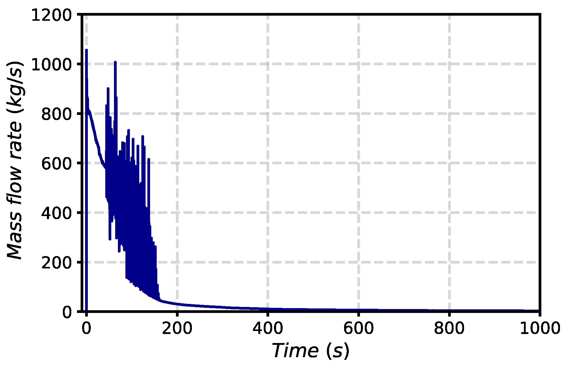
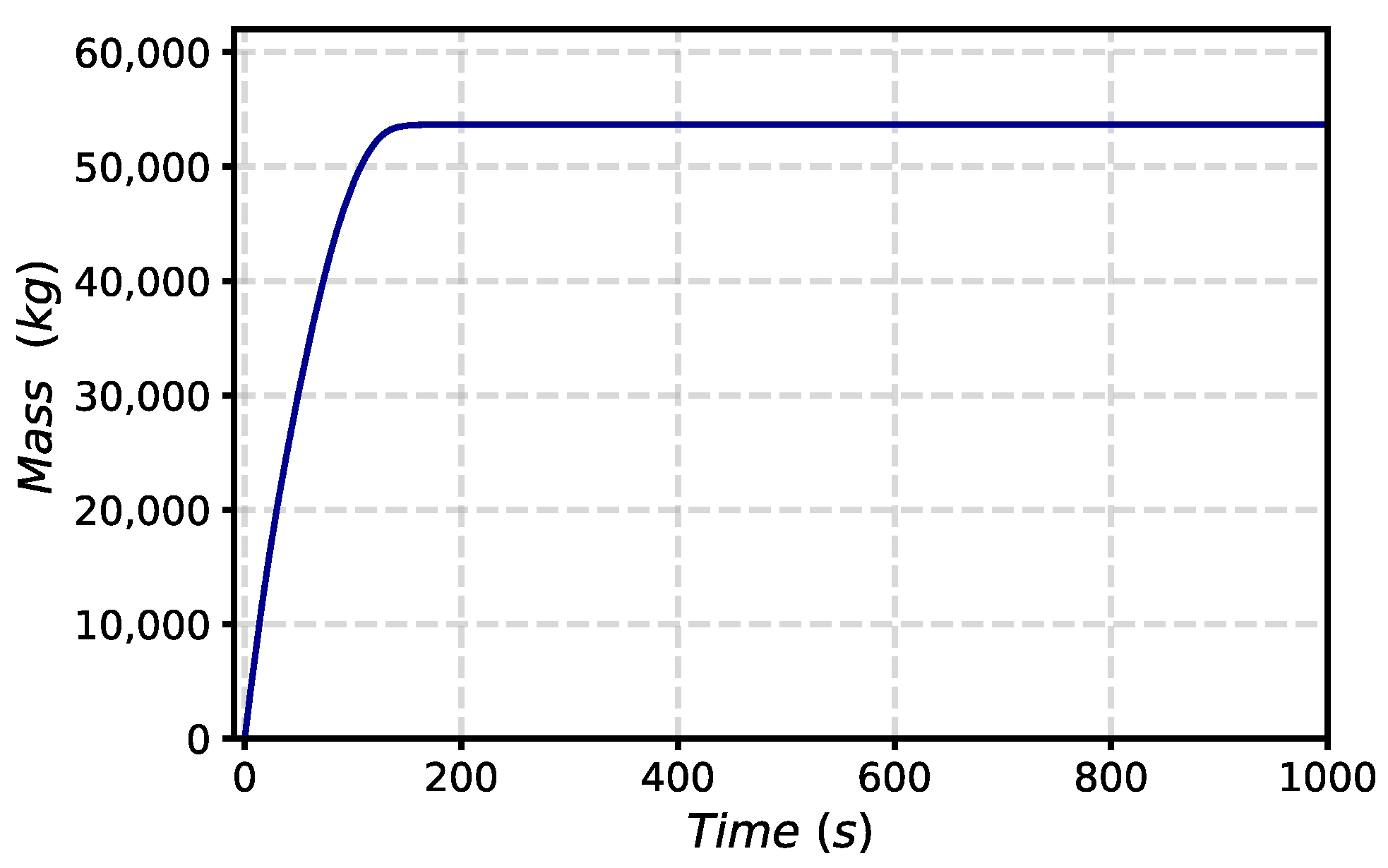
In both simulations, the postulated initiating event occurs at time 0.0 s. Due to the high energy content difference between the PHTS and the VV, the coolant is discharged toward the vessel, vaporizing instantly. The water mass flow rate transient from the failure of FW channels is shown in Figure 8. The maximum flow rate toward the VV is 1055 kg/s. After the peak, the differential pressure between the PHTS and VV decreases, and the mass flow rate decreases until both environments reach an equilibrium. As shown in Figure 9, about 53 tons of water are discharged from FW-PHTS into the VV at the end of the transient. The release of this amount of water within the VV leads to rapid pressurization of the VV volumes causing the triggering of bleed lines and rupture discs with the mobilization of hydrogen and steam in the VVPSS tanks.
3.1.1. PAR Installed in Each Suppression Tank
In this case, preliminary simulations have been performed assuming 150 kPa as the setpoint for the trigger of VVPSS-RDs and 90 kPa for the opening of bleed lines and that each ST is filled with 60% water.
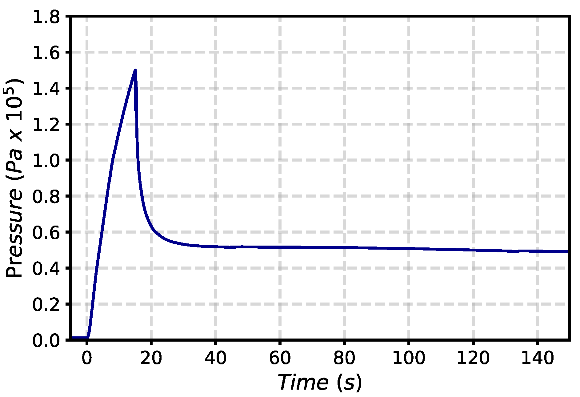
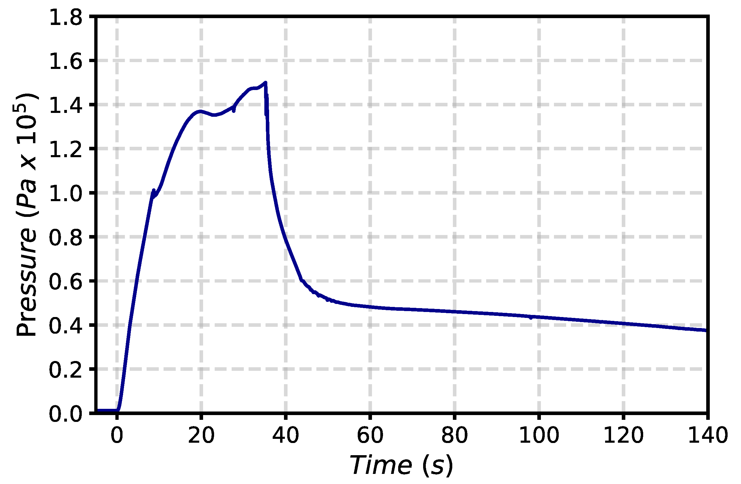
After the in-vessel LOCA, pressure in the VV increases very quickly and reaches the maximum value of 150 kPa, limited by the pressure suppression system below the design pressure of 200 kPa, in around 15.0 s (Figure 10). As soon as the pressure peak is reached, the pressure starts to decrease due to the triggering rupture disk lines connecting the VV to the VVPSS, where the suppression water, initially at 40 °C, is available for condensing the steam arising from the FW-PHTS.
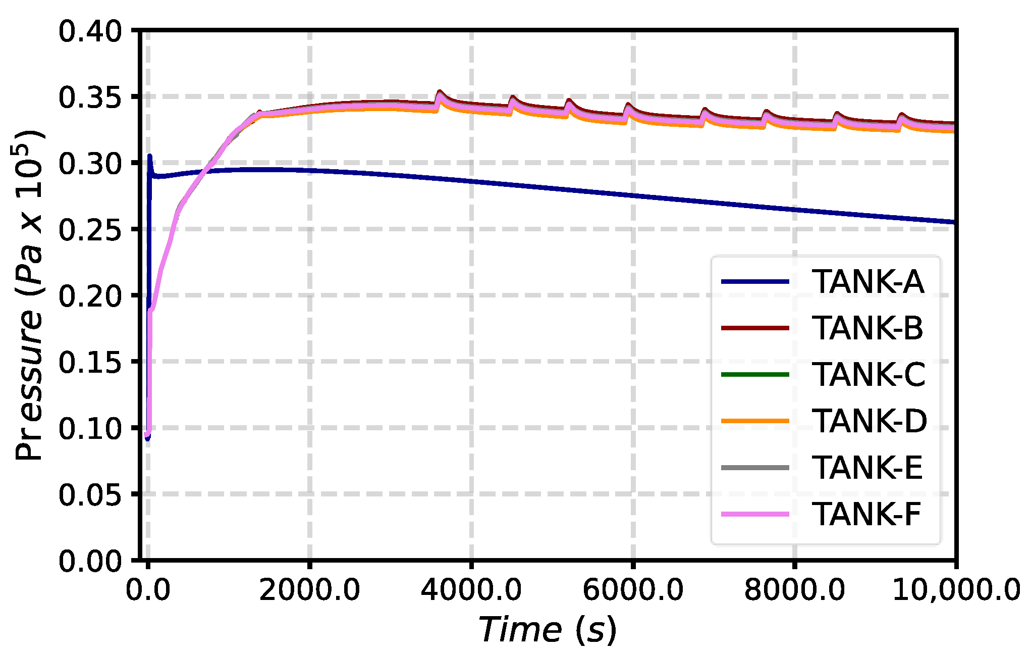
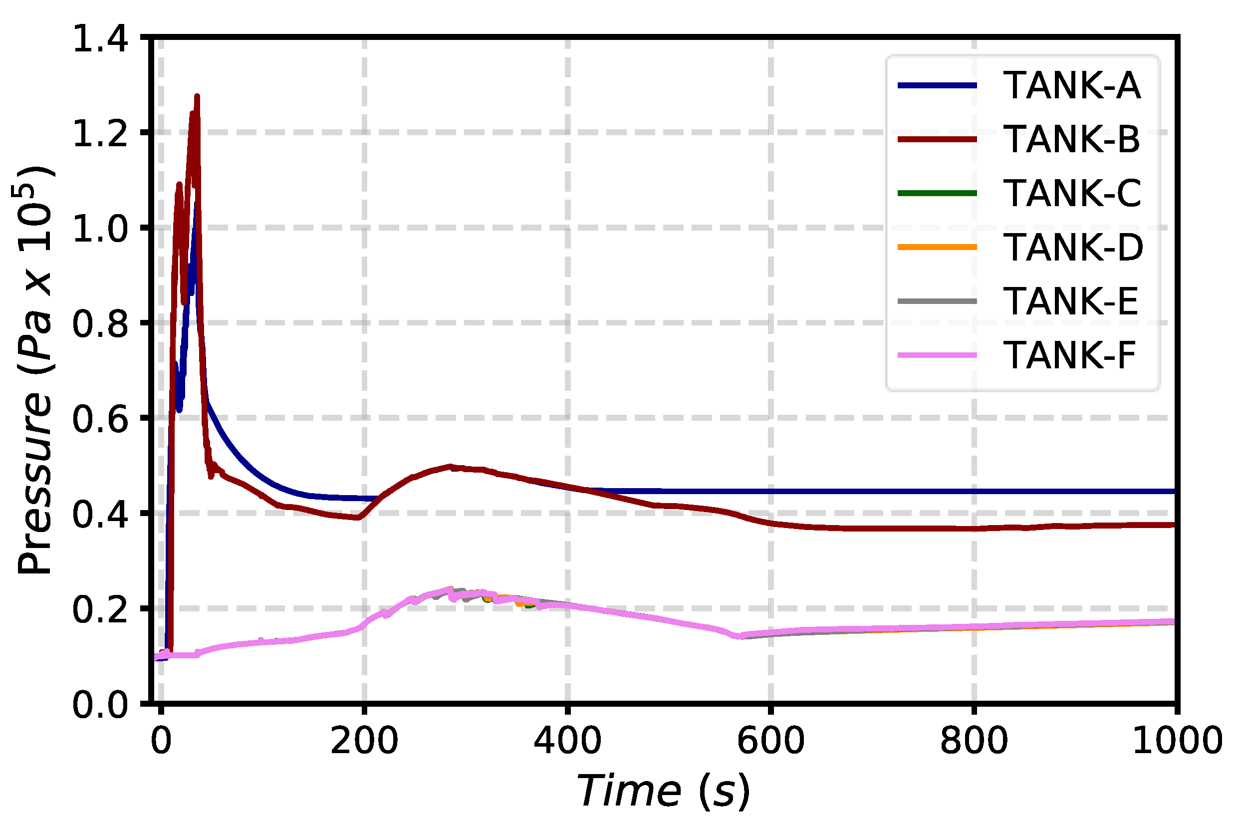
Being the maximum pressure reached in the VV equal to 150 kPa, the mass of hydrogen and steam will be discharged in all the VVPSS suppression tanks. The injection of hot steam and hydrogen inside the VVPSS causes an increase in the pressure and temperature of the VVPSS tanks. Pressure waveforms in VVPSS tanks are shown in Figure 11. STs have been initialized at 9.479 kPa; the maximum pressure reached in tank A is 30.5 kPa, which is well below the atmospheric pressure. The maximum pressure is reached a few seconds after the opening of BLs, around 18.0 s after the PIE. Water and hydrogen injection in tank A stops when the pressure in VV returns below 90 kPa (~18.0 s after the PIE). The pool temperature in tank A remains at around 315.5 K for the entire simulation, while the atmosphere temperature reaches a maximum of 375 K when the BLs open. Concerning STs B to F, the pressurization starts 15 s after the PIE when the rupture discs are triggered. The maximum pressure of 35 kPa is reached 3000 s after the PIE. The pool temperature in the STs B-F increases from the initial value of 313 K to 334 K, while the atmosphere reaches a maximum of 355 K after the RDs opening, and then remains at around 340 K.
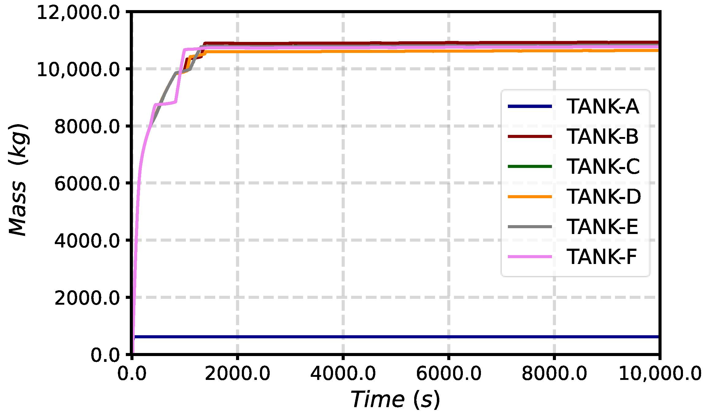
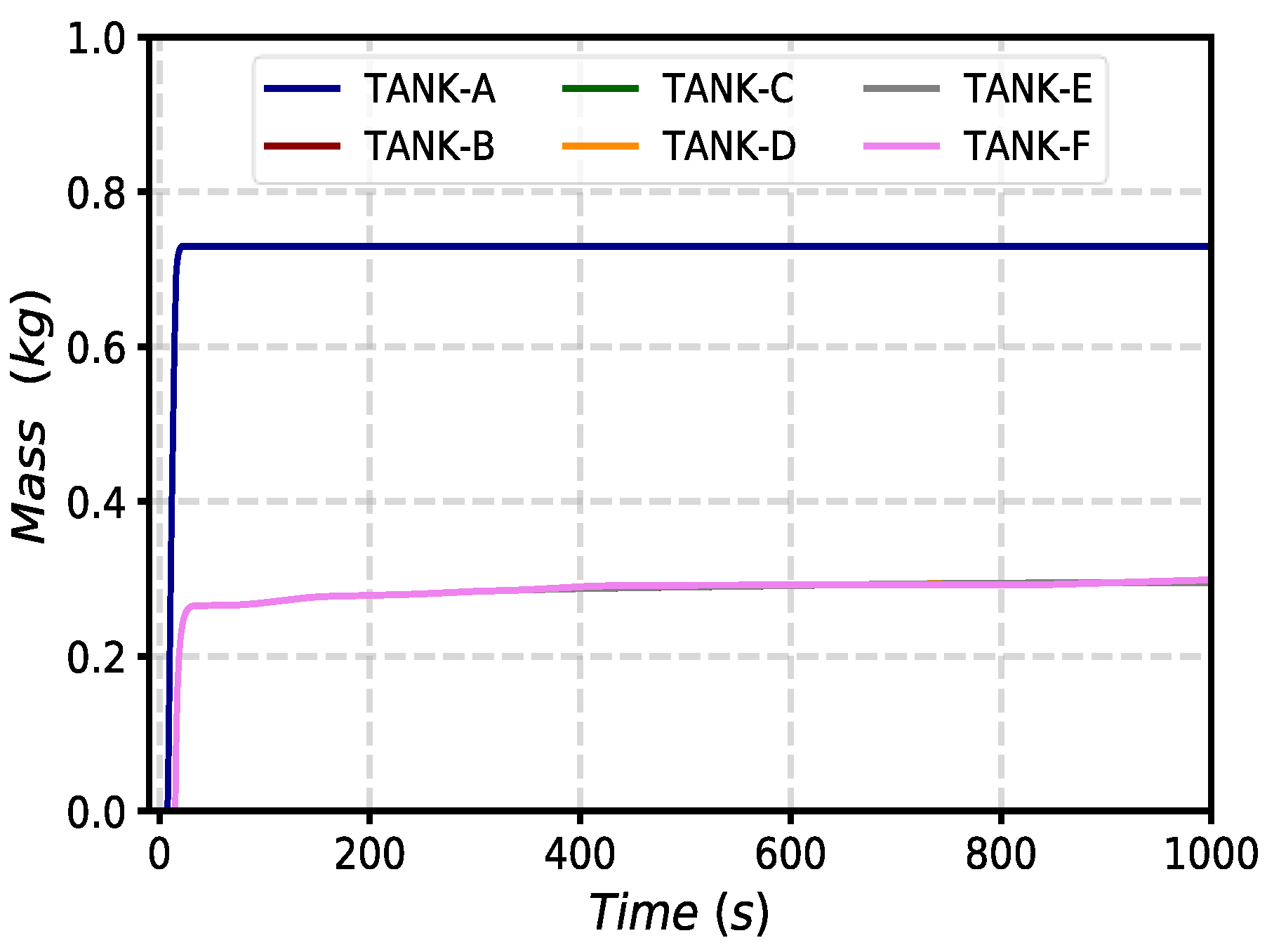
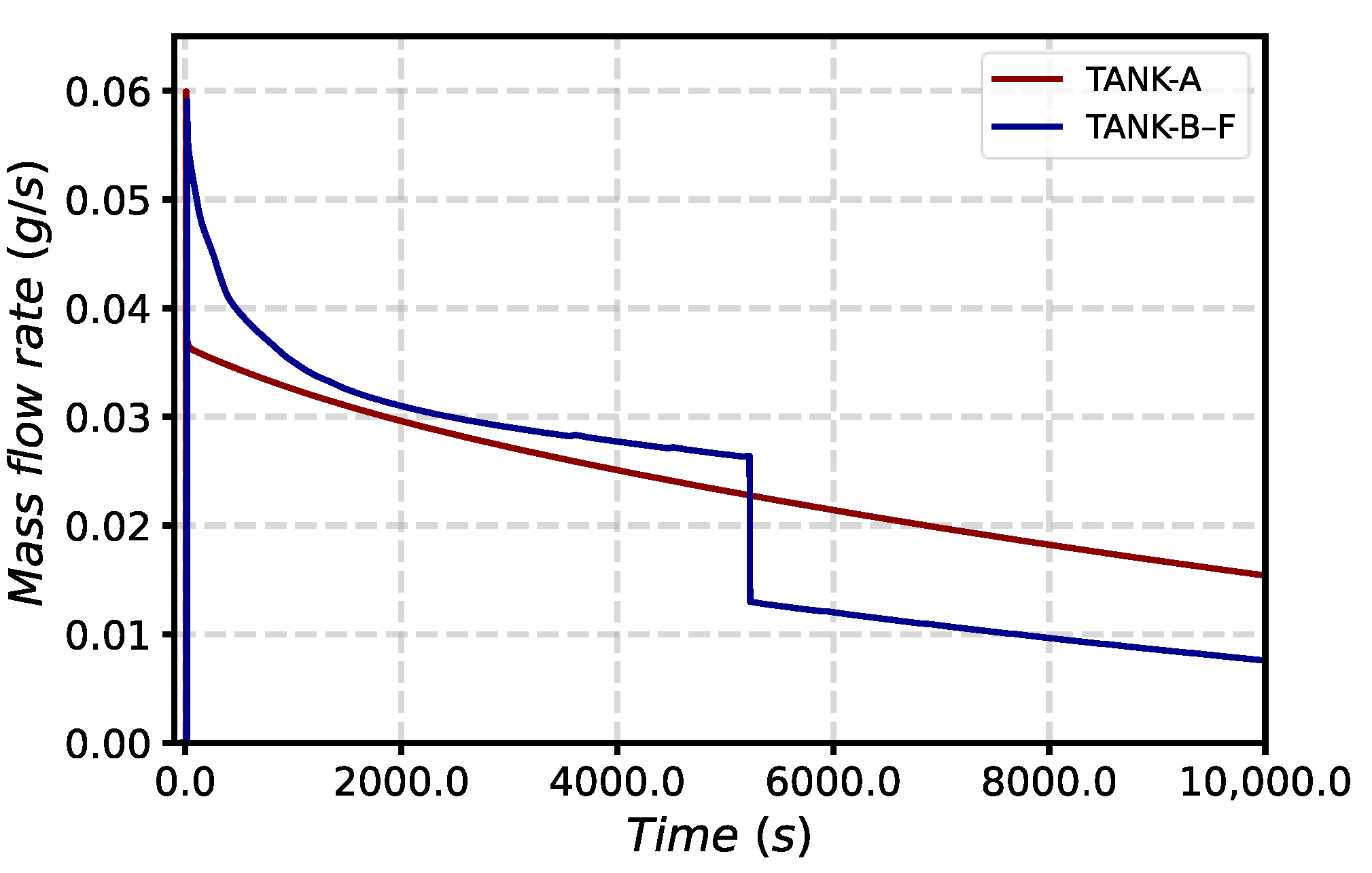
The total mass of steam discharged into STs B-F is around 10.9 tons, while 613.85 kg of steam is discharged in tank A (Figure 12). Concerning hydrogen, 0.72 kg of H2 enters tank A, while around 0.306 kg is discharged in each ST. Some hydrogen also remains inside the VV volumes. The results in Figure 13 show the total mass of hydrogen entering the VVPSS tanks. Concerning tank A, the atmosphere is filled with air at the beginning, and the mole fraction of O2 is 0.21. After the opening of the bleed lines, the atmosphere of the tank is filled with around 8.46% of O2, 30.17% of N2, 28% of steam, 30.56% of hydrogen, and 2.73% of helium coming from VV. The ratio between the hydrogen and oxygen mole fraction is higher than 0.5 for the entire simulation time; thus, the recombination reaction takes place in the presence of excess hydrogen, and the mole fraction of oxygen is used to evaluate the recombined mass hydrogen. The maximum rate of 0.06 g/s is at the opening of the bleed lines and then decreases to 0.035 g/s in 10 s.
Similar considerations can be conducted for other suppression tanks (B to F). However, since the rupture discs opening occurs later than the BLs and the remaining hydrogen is divided among the five STs, the behavior in those tanks could be different than that described for tank A. After the opening of the rupture discs, 20 s after the PIE, the atmosphere of the tank is filled with around 14.2% of O2, 50.7% of N2, 25.3% of steam, 9% of hydrogen, and 0.75% of helium coming from VV. The mole fraction ratio drops below 0.5 after around 5000 s, causing a sudden change in the recombination rate. Following Equation (1), after 5000 s, the mole fraction used is the one of hydrogen, causing a drop in the recombination rate effectiveness. The maximum rate of 0.06 g/s is at the opening of the rupture discs and then slowly decreases to 0.028 g/s following the trend of oxygen mole fraction. The hydrogen recombination rate for a single PAR unit in VVPSS suppression tanks is shown in Figure 14.
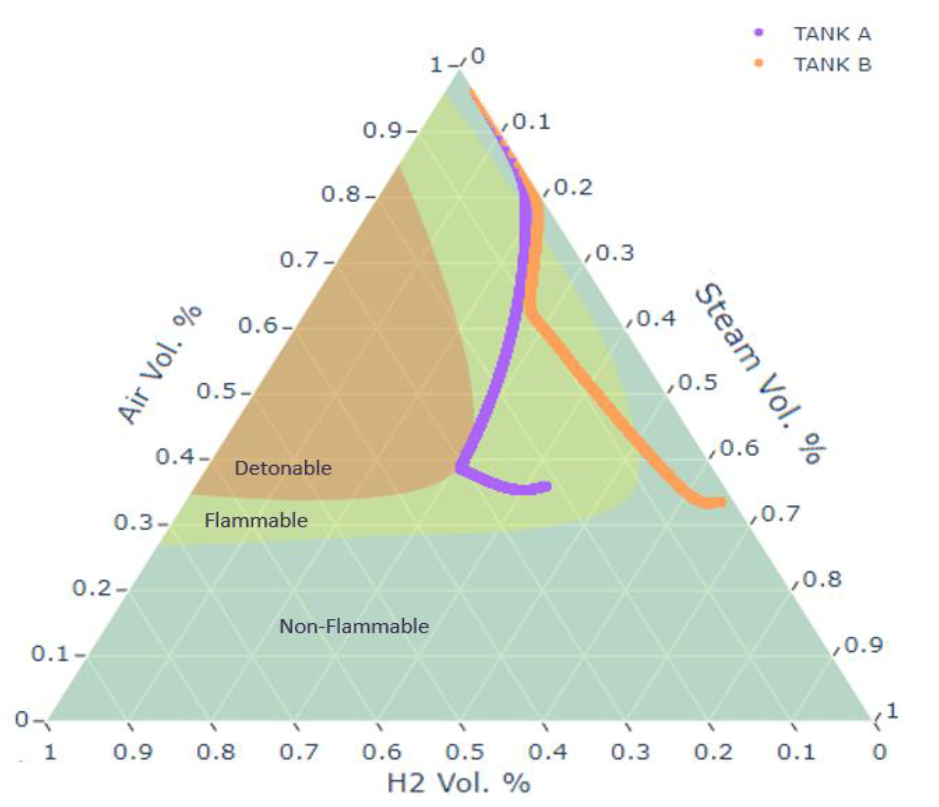
After 10,000 s of the total amount of hydrogen entered in tank A (720 g), around 250 g (34.7%) has been removed. After 10,000 s of the total amount of hydrogen entered in tank B (306 g), around 219 g (71%) has been removed. After 10,000 s of the simulation, the total mass of hydrogen has been reduced to 1.327 kg, which is around 50% of the initial hydrogen inventory. Based on the adopted assumptions, a significant amount of hydrogen (mainly tritium) remains available, leaving a residual risk in the case of a possible VVPSS leakage. The results highlighted that PARs could be a good solution to remove hydrogen long term. However, as shown in Figure 15, for the adopted VVPSS configuration, problems can arise as soon as the rupture discs or bleed valves open because of the high mole fraction of hydrogen reached in each suppression tank.
3.1.2. Proposed VVPSS Design
Since the main objective is to preclude the occurrence of flammable gas mixtures, the previous solution should be modified. For this purpose, the suppression tanks have been initialized in saturated conditions, without air (oxygen) in the atmosphere. Thus, as shown in Figure 7, expansion tanks have been added to the system to ensure hydrogen recombination, and the VVPSS design has been slightly modified to maximize hydrogen mobilization inside these ETs.
As soon as the in-vessel LOCA occurs, pressure in the VV increases very quickly and reaches 40 kPa (setpoint for BL opening) in around 3.47 s. Starting from this point, steam and hydrogen are discharged inside tank A; however, the flow area of BL is not enough to mitigate VV pressurization. After 8.5 s from the PIE, the pressure in the VV reaches 100 kPa and the RD lines toward the suppression tank B are opened. The setpoint of 150 kPa for the triggering of other RDs is reached at 35.25 s. The VV pressurization trend is shown in Figure 16. The timing of the BL and RD openings are summarized in Table 1. The maximum pressure of 150 kPa (below the design pressure of 200 kPa) is limited by the pressure suppression system. After the complete opening of all RDs, the pressure inside the VV starts to decrease since all the steam arising from the FW-PHTS is condensed inside the suppression tanks.
The injection of hot steam and hydrogen inside the VVPSS causes an increase in the pressure and temperature of the VVPSS tanks. It is important to consider these values (in particular for tanks A and B) because they can affect the mass of hydrogen moved toward the expansion tanks, where the PARs are located. Pressure waveforms in VVPSS tanks are shown in Figure 17. The pressure in tank A reaches 40 kPa (setpoint for discharging in ET-A) after 7.44 s from the PIE. The maximum pressure of 105 kPa is reached in tank A at 35.3 s. The maximum pressure in tank B is 127.5 kPa and it is reached 35.3 s after the PIE. The pressure in tank B reaches 40 kPa (setpoint for discharging in ET-B) after 9.765 s from the PIE.
In all the other suppression tanks (C to F), because of the higher mass of water available for steam condensation, the pressure increases from 9.5 kPa to 18.5 kPa in around 3000 s.
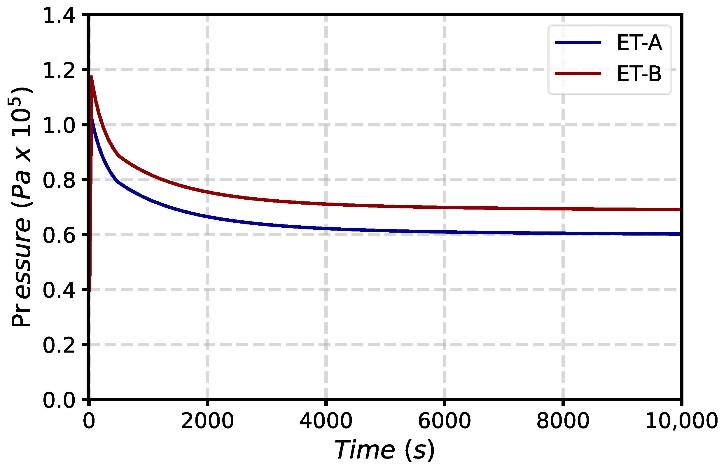
The pressure waveforms of the expansion tanks A and B are shown in Figure 18. The maximum pressures in ET-A and ET-B are 102 kPa and 117.47 kPa, respectively. Since the expansion tanks are connected to the VVPSS suppression tanks through non-return valves, the pressure in ETs remains higher than the pressure in STs in the long-term scenario. This allows more efficient hydrogen recombination.
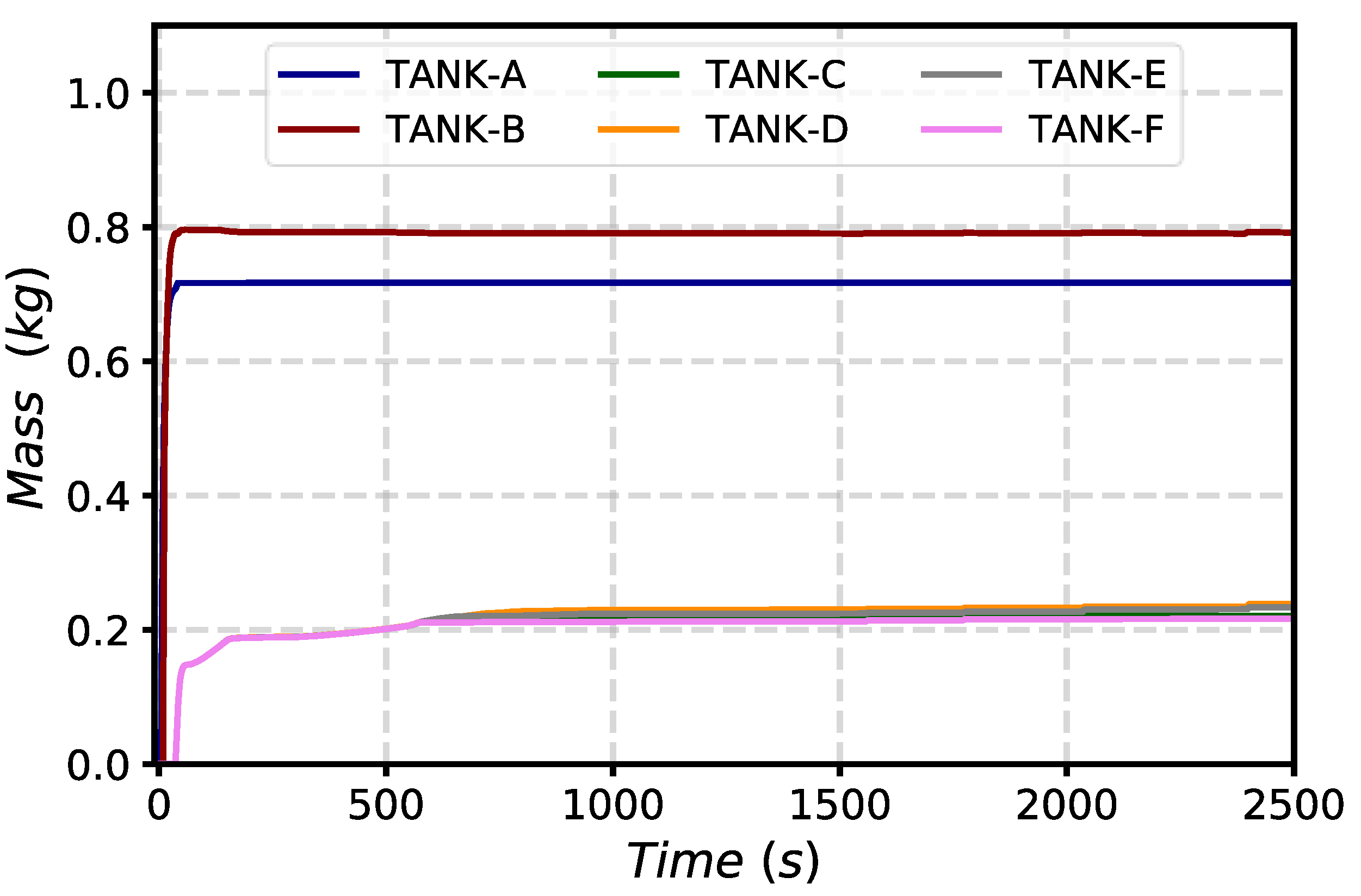
The total mass of steam discharged into the STs C-F is around 37.1 tons, while 1973 kg of steam is discharged in tank A and 3389 kg in tank B. Concerning hydrogen, the anticipated opening of BVs allows the mobilization of 716.8 g of H2 in tank A, while around 796.4 g is discharged in ST-B. Around 220 g of hydrogen is moved in the other ST when the pressure in VV reaches 150 kPa. Some hydrogen (about 300 g) also remains inside the VV volumes. Results in Figure 19 show the total mass of hydrogen entering the VVPSS tanks.
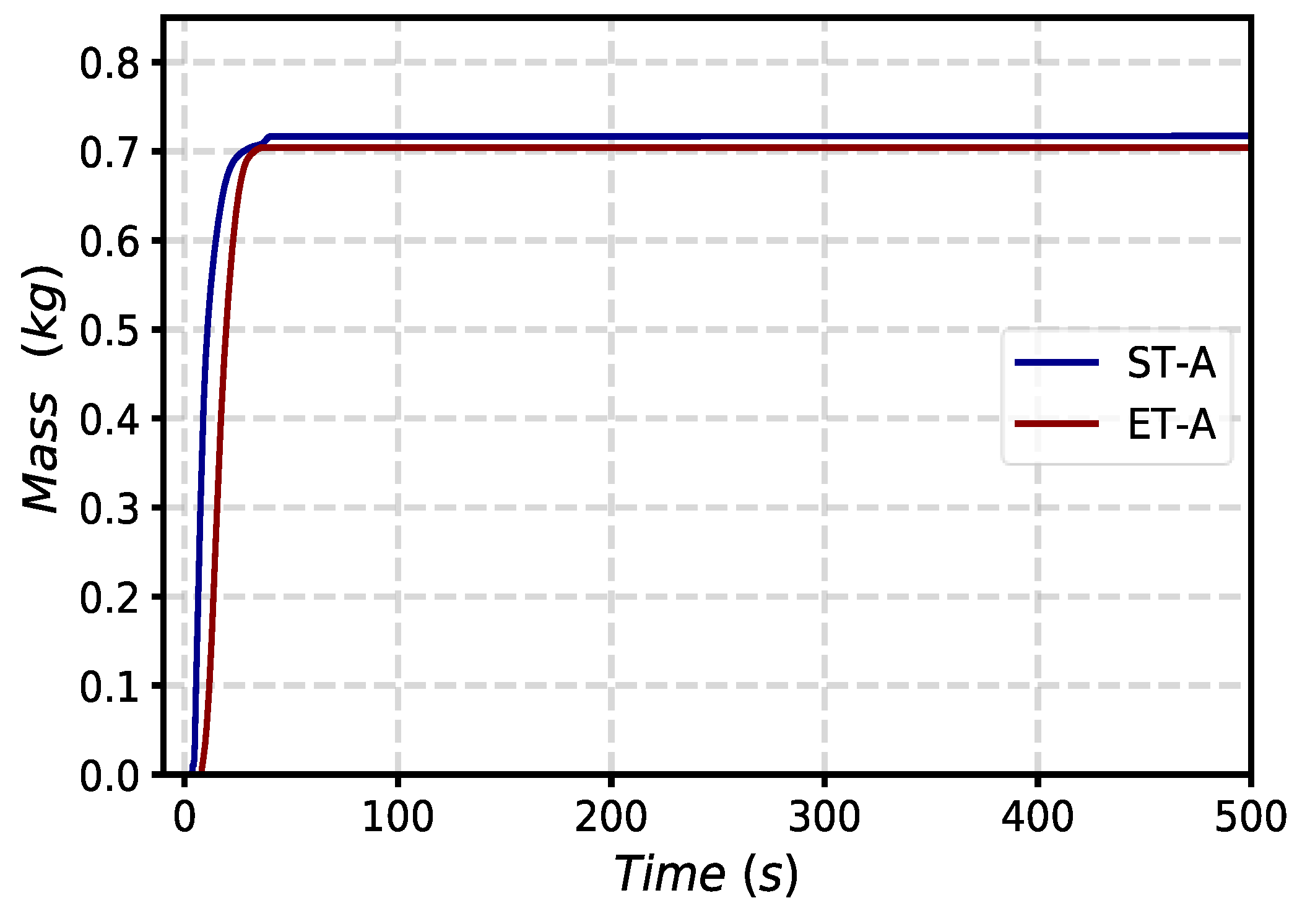
In Figure 20 and Figure 21, the mass entering the ETs is compared with the mass entering tank A and tank B, respectively. Of the 716.8 g of H2 moved in ST-A, 704.1 g is transferred toward the expansion tank. As well as, of the 796.4 g of H2 discharged in ST-B, 773.5 g moves into ET-B.
Since both ETs are filled with air, the recombination reaction takes place in the presence of excess oxygen and, following Equation (3), the mole fraction of hydrogen is used for the evaluation of the recombined mass of hydrogen.
In Figure 22, the hydrogen recombination rate for a single PAR unit is shown for ET-A and ET-B, respectively. The PAR in ET-A recombines hydrogen with a mass flow rate of around 0.016 g/s, while in ET-B, the recombination rate is slightly higher, around 0.019 g/s. The difference in the recombination rates is due to the operating pressure of ET-B, which is slightly higher than the pressure in ET-A.
As shown in Figure 23, after 10,000 s of the total amount of hydrogen entered in ET-A (704.1 g), about 154 g (21.87%) has been removed by a single PAR unit. Concerning ET-B, after 10,000 s of the 773.5 g of H2, about 180 g (23.27%) has been removed by a single PAR unit.
After 10,000 s of the simulation, the total mass of hydrogen has been reduced to 2.339 kg, which is around 87% of the initial hydrogen inventory. However, those results have been obtained using only two PAR units, minimizing the risk of hydrogen explosion. Moreover, since a large part of the hydrogen is moved in the expansion tanks, the results can be improved by installing additional PAR units. As shown in Figure 24 and Figure 25, the risk of hydrogen explosion inside the suppression system is significantly reduced compared with the previous results shown in Figure 15.
4. Discussion
Analyses of the source term and hydrogen mobilization, performed for the EU-DEMO reactor, highlighted that the Fisher-based hydrogen recombination model implemented in MELCOR 1.8.6 presents some limitations for simulating the possible recombination phenomenon of recombiners operating at a low pressure [1]. For this reason, a new model has been developed in MELCOR to study the effectiveness of PAR recombiners installed in the tokamak pressure suppression system. The model evaluates the mass of hydrogen recombined according to the operating pressure and the hydrogen and oxygen molecular quantity. Analyses of an in-vessel LOCA have been performed to investigate the behavior of the hydrogen mitigation system during accidental conditions. Preliminary studies have demonstrated that PARs in each VVPSS suppression tank are quite effective in terms of hydrogen recombination. However, problems of hydrogen accumulation in the atmosphere of suppression tanks can arise, increasing the risk of an explosion. To overcome this problem, some modifications to the pressure suppression system design have been proposed by varying the opening setpoint of bleed valves and rupture disks and the water level inside some suppression tanks. Moreover, two expansion tanks have been added to the system, where part of the hydrogen is collected and recombined.
The results have highlighted that the proposed preliminary solution, in terms of the hydrogen explosion risk, is more effective than installing PAR in each suppression tank. Moreover, it could allow reasonable amounts of hydrogen recombination, which could be further increased by refining preliminary assumptions and increasing the number of PAR units inside the expansion tanks.
Since one of the main objectives of safety studies is to preclude the occurrence of flammable gas mixtures in DEMO nuclear plants, the research of technical solutions to avoid the risk of hydrogen explosion should continue in future activities.
5. Conclusions
The proposed research aimed to demonstrate the theoretical effectiveness of a passive recombination system that could be installed in the VVPSS of the EU-DEMO. The solution to this numerical analysis has been solved by the MELCOR system code. A model of the system and the accident sequence has been modeled according to the design concept being developed in the EUROfusion consortium.
Two different approaches have been analyzed. At first, the PAR units were installed in the suppression tanks of the VVPSS, and the results evidenced an efficient recombination of hydrogen, although the composition of the atmosphere reached a flammable concentration during the transient, highlighting a risk concern. Therefore, a second approach is suggested, based on the installment of the PAR unit in a separate tank connected to the suppression tanks. The simulation estimated an efficient recombination of hydrogen without a risk concern in terms of deflagration or detonation.
Future activities will explore the optimization of the VVPSS in terms of hydrogen recombination. The thermal-hydraulic parameters, such as the liquid level inside the suppression tanks, will be analyzed further to understand if a higher amount of hydrogen could be recombined by the system, changing some boundary conditions of the problem.
Author Contributions
Conceptualization, M.D., T.G. and G.C.; methodology, M.D., T.G., M.T.P., G.M. and G.C.; software, M.D.; validation, M.D. and T.G.; writing—original draft preparation, M.D., T.G. and G.C.; writing—review and editing, M.D., T.G., M.T.P., G.M. and G.C. All authors have read and agreed to the published version of the manuscript.
Funding
This work was carried out within the framework of the EUROfusion consortium, funded by the European Union via the Euratom Research and Training Program (grant agreement no. 101052200—EUROfusion). The views and opinions expressed are, however, those of the author(s) only and do not necessarily reflect those of the European Union or the European Commission. Neither the European Union nor the European Commission can be held responsible for them.
Data Availability Statement
Data are available only for institutions involved in the EUROfusion project. For that organization, the data presented in this study are available on request from the corresponding author.
Conflicts of Interest
The authors declare no conflict of interest. The funders had no role in the design of the study; in the collection, analyses, or interpretation of data; in the writing of the manuscript, or in the decision to publish the results.
Abbreviations
| BB | Breeding Blanket |
| BL | Bleed Line |
| BSS | Back-Supporting Structure |
| BZ | Breeder Zone |
| CFs | Control Functions |
| CVs | Control Volumes |
| DWTs | Double Wall Tubes |
| ET | Expansion Tank |
| EU-DEMO | European DEMOnstratation |
| FLs | Flow Paths |
| FW | First Wall |
| HS | Heat Structures |
| IB | InBoard |
| LOCA | Loss-Of-Coolant Accident |
| OB | OutBoard |
| PARs | Passive Autocatalytic Recombiners |
| PFC | Plasma-Facing Component |
| PHTS | Primary Heat Transfer System |
| PIEs | Postulated Initiating Events |
| RD | Rupture Disk |
| SAE | Safety And Environment |
| SDL | Safety Data List |
| SRV | Safety Relief Valve |
| VV | Vacuum Vessel |
| VVPSS | Vacuum Vessel Pressure Suppression System |
| WCLL | Water-Cooled LithiumLead |
| WCS | Water Coolant System |
References
- Mazzini, G.; D’Onorio, M.; Caruso, G. Hydrogen explosion mitigation in DEMO vacuum vessel pressure suppression system using passive recombiners. Fusion Eng. Des. 2021, 171, 112713. [Google Scholar] [CrossRef]
- Taylor, N.; Ciattaglia, S.; Coombs, D.; Jin, X.Z.; Johnston, J.; Liger, K.; Mazzini, G.; Mora, J.C.; Pinna, T.; Porfiri, M.T.; et al. Safety and environment studies for a European DEMO design concept. Fusion Eng. Des. 2019, 146, 111–114. [Google Scholar] [CrossRef]
- Porfiri, M.T.; Taylor, N.; Ciattaglia, S.; Jin, X.Z.; Johnston, J.; Colling, B.; Eade, T.; Carloni, D.; Pinna, T.; Urbonavicius, E.; et al. Safety assessment for EU DEMO—Achievements and open issues in view of a generic site safety report. Fusion Eng. Des. 2020, 155, 111541. [Google Scholar] [CrossRef]
- Caruso, G.; Ciattaglia, S.; Colling, B.; Di Pace, L.; Dongiovanni, D.N.; D’Onorio, M.; Garcia, M.; Jin, X.Z.; Johnston, J.; Leichtle, D.; et al. DEMO—The main achievements of the Pre-Concept phase of the safety and environmental work package and the development of the GSSR. Fusion Eng. Des. 2022, 176, 113025. [Google Scholar] [CrossRef]
- Spagnuolo, G.A. Integrated design of breeding blanket and ancillary systems related to the use of helium or water as a coolant and impact on the overall plant design. Fusion Eng. Des. 2021, 173, 112933. [Google Scholar] [CrossRef]
- OECD International Energy Agency. World Energy Outlook 2021. Available online: https://www.iea.org/reports/world-energy-outlook-2021 (accessed on 2 March 2023).
- Power Reactor Information System (PRIS). Nuclear Power Status 2021, IAEA. 2021. Available online: https://pris.iaea.org/pris/PRIS_poster_2021.pdf (accessed on 25 February 2023).
- Tong, L.S.; Weisman, J. Thermal Analysis of Pressurized Water Reactors, United States. 1979. Available online: http://www.gammaexplorer.com/wp-content/uploads/2014/03/Thermal-Analysis-of-Pressurized-Water-Reactors-Tong.pdf (accessed on 10 January 2023).
- Joyce, M. A Conceptual Introduction to Nuclear Power, Nuclear Engineering. 2018. Available online: https://www.sciencedirect.com/book/9780081009628/nuclear-engineering (accessed on 25 February 2023).
- IAEA. Heavy Water Reactors: Status and Project Development, International Atomic Energy Agency, Technical Reports Series; IAEA: Vienna, Austria, 2002; ISSN 0074–1914. Available online: https://www-pub.iaea.org/MTCD/publications/PDF/TRS407_scr/D407_scr1.pdf (accessed on 25 February 2023).
- IAEA. Advances in Small Modular Reactor Technology Developments, in IAEA Advanced Reactor Information System (ARIS); IAEA: Vienna, Austria, 2014; Available online: https://aris.iaea.org/Publications/SMR_Book_2020.pdf (accessed on 25 February 2023).
- Donné, A.J.H. The European roadmap towards fusion electricity. Phil. Trans. R. Soc. A 2019, 377, 20170432. [Google Scholar] [CrossRef] [Green Version]
- D’Onorio, M.; Giannetti, F.; Porfiri, M.T.; Caruso, G. Preliminary safety analysis of an in-vessel LOCA for the EU-DEMO WCLL blanket concept. Fusion Eng. Des. 2020, 155, 111560. [Google Scholar] [CrossRef]
- D’Onorio, M.; Giannetti, F.; Caruso, G.; Porfiri, M.T. In-box LOCA accident analysis for the European DEMO water-cooled reactor. Fusion Eng. Des. 2019, 146, 732–735. [Google Scholar] [CrossRef] [Green Version]
- Eboli, M.; Forgione, N.; Del Nevo, A. Assessment of SIMMER-III code in predicting water cooled lithium lead breeding blanket “in-box-Loss of Coolant Accident”. Fusion Eng. Des. 2021, 163, 112127. [Google Scholar] [CrossRef]
- Gupta, S.; Schmidt, E.; von Laufenberg, B.; Freitag, M.; Poss, G.; Funke, F.; Weber, G. THAI test facility for experimental research on hydrogen and fission product behaviour in light water reactor containments. Nuclear Eng. Des. 2015, 294, 183–201. [Google Scholar] [CrossRef]
- Flores y Flores, A.; Mazzini, G. Analyses of THAI 1 hydrogen deflagration using MELCOR code version 2.1 and 2.2. Nuclear Eng. Des. 2020, 369, 110838. [Google Scholar] [CrossRef]
- Gauntt, R.O.; Cole, R.K.; Erickson, C.M.; Gido, R.I.G.; Gasser, R.D.; Rodriguez, S.B.; Young, M.F. MELCOR Computer Code Manuals Vol. 1: Primer and Users Guide Version 1.8.6, NUREG/CR-6119, Volume 1, Rev. 3; Sandia National Laboratory: Albuquerque, NM, USA, 2005. [Google Scholar]
- Merrill, B.J.; Humrickhouse, P.W.; Moore, R.L. A recent version of MELCOR for fusion safety applications. Fusion Eng. Des. 2010, 85, 1479–1483. [Google Scholar] [CrossRef]
- Del Nevo, A.; Arena, P.; Caruso, G.; Chiovaro, P.; Di Maio, P.; Eboli, M.; Edemetti, F.; Forgione, N.; Forte, R.; Froio, A.; et al. Recent progress in developing a feasible and integrated conceptual design of the WCLL BB in EUROfusion project. Fusion Eng. Des. 2019, 146, 1805–1809. [Google Scholar] [CrossRef] [Green Version]
- Federici, G.; Boccaccini, L.; Cismondi, F.; Gasparotto, M.; Poitevin, Y.; Ricapito, I. An overview of the EU breeding blanket design strategy as an integral part of the DEMO design effort. Fusion Eng. Des. 2019, 141, 30–42. [Google Scholar] [CrossRef]
- Zhou, G.; Hernández, F.A.; Zeile, C. A methodology for thermo-mechanical assessment of in-box LOCA events on fusion blankets and its application to EU DEMO HCPB breeding blanket. Kerntechnik 2018, 83, 256–260. [Google Scholar] [CrossRef] [Green Version]
- Martelli, E.; Giannetti, F.; Caruso, G.; Tarallo, A.; Polidori, M.; Barucca, L.; Del Nevo, A. Study of EU DEMO WCLL breeding blanket and primary heat transfer system integration. Fusion Eng. Des. 2018, 136, 828–833. [Google Scholar] [CrossRef]
- Barucca, L.; Bubelis, E.; Ciattaglia, S.; D’Alessandro, A.; Del Nevo, A.; Giannetti, F.; Hering, W.; Lorusso, P.; Martelli, E.; Moscato, I.; et al. Pre-conceptual design of EU DEMO balance of plant systems: Objectives and challenges. Fusion Eng. Des. 2021, 169, 112504. [Google Scholar] [CrossRef]
- Caruso, G.; Giannetti, F. Sizing of the Vacuum Vessel Pressure Suppression System of a Fusion Reactor Based on a Water-Cooled Blanket, for the Purpose of the Preconceptual Design. Sci. Technol. Nucl. Install. 2016, 2016, 871969. [Google Scholar] [CrossRef] [Green Version]
- Barucca, L.; Ciattaglia, S.; Chantant, M.; Del Nevo, A.; Hering, W.; Martelli, E.; Moscato, I. Status of EU DEMO heat transport and power conversion systems. Fusion Eng. Des. 2018, 136, 1557–1566. [Google Scholar] [CrossRef]
- D’Onorio, M.; Giannetti, F.; Porfiri, M.T.; Caruso, G. Preliminary sensitivity analysis for an ex-vessel LOCA without plasma shutdown for the EU DEMO WCLL blanket concept. Fusion Eng. Des. 2020, 158, 111745. [Google Scholar] [CrossRef]
- Bachmann, C.; Ciattaglia, S.; Cismondi, F.; Federici, G.; Franke, T.; Gliss, C.; Härtl, T.; Keech, G.; Kembleton, R.; Maviglia, F.; et al. Key design integration issues addressed in the EU DEMO pre-concept design phase. Fusion Eng. Des. 2020, 156, 111595. [Google Scholar] [CrossRef]
- D’Onorio, M.; Caruso, G. Pressure suppression system influence on vacuum vessel thermal-hydraulics and on source term mobilization during a multiple first Wall—Blanket pipe break. Fusion Eng. Des. 2021, 164, 112224. [Google Scholar] [CrossRef]
- Kotouč, M. Výstupy a doporučení plynoucí z projektu OECD/NEA THAI-2. In Technical Report ÚJV Z-4882-T; ÚJV Rež, a.s.: Husinec, Czech Republic, 2017. [Google Scholar]
- Pinna, T.; Carloni, D.; Carpignano, A.; Ciattaglia, S.; Johnston, J.; Porfiri, M.; Savoldi, L.; Taylor, N.; Sobrero, G.; Uggenti, A.; et al. Identification of accident sequences for the DEMO plant. Fusion Eng. Des. 2017, 124, 1277–1280. [Google Scholar] [CrossRef]
- Pinna, T.; Dongiovanni, D.N.; Ciattaglia, S.; Barucca, L. Safety important classification of EU DEMO components. Fusion Eng. Des. 2019, 146, 631–636. [Google Scholar] [CrossRef]
- Mazzini, G.; Kaliatka, T.; Porfiri, M.T. Estimation of tritium and dust source term in european DEMOnstration fusion reactor during accident scenarios. J. Nuclear Rad. Sci. 2019, 5, 4043379. [Google Scholar] [CrossRef]
- Mazzini, G.; Kaliatka, T.; Porfiri, M.T. Tritium and Dust Source Term Inventory Evaluation Issues in the European DEMO reactor concepts. Fusion Eng. Des. 2019, 146, 510–513. [Google Scholar] [CrossRef]
Figure 1.
WCLL central outboard equatorial cell.

Figure 2.
EU-DEMO PHTS.

Figure 3.
EU-DEMO VVPSS [25].
Figure 3.
EU-DEMO VVPSS [25].

Figure 4.
EU-DEMO MELCOR PHTS nodalization scheme.

Figure 5.
EU-DEMO baseline CAD model [28].
Figure 5.
EU-DEMO baseline CAD model [28].

Figure 6.
EU-DEMO vacuum vessel nodalization scheme.

Figure 7.
MELCOR model PSS tanks and ETs.

Figure 8.
Mass flow rate entering the VV.

Figure 9.
Mass of water entering the VV.

Figure 10.
Pressure in plasma chamber volume.

Figure 11.
Pressure in VVPSS tanks.

Figure 12.
Mass of steam entering VVPSS tanks.

Figure 13.
Hydrogen mass distribution into the tanks.

Figure 14.
Hydrogen recombination rate for a single PAR in tanks A and B–F.

Figure 15.
Flammability triangle for tank A and tank B.

Figure 16.
Pressure in plasma chamber volume.

Figure 17.
Pressure in VVPSS tanks.

Figure 18.
Pressure in ET volumes (CV978 and CV979).

Figure 19.
Mass of hydrogen entering VVPSS tanks.

Figure 20.
Mass H2 entering ET-A vs. mass H2 entering ST-A.

Figure 21.
Mass H2 entering ET-B vs. mass H2 entering ST-B.

Figure 22.
Hydrogen recombination rate for a single PAR in expansion tanks.

Figure 23.
Mass of H2 recombined by single PAR in expansion tanks.

Figure 24.
Flammability triangle for suppression tanks A and B.

Figure 25.
Flammability triangle for expansion tanks A and B.


Table 1.
Timing of vacuum vessel pressurization.
| VV Pressure (kPa) | Safety Device Triggered | VVPSS ST | Time (s) |
|---|---|---|---|
| 40 | BV | Tank A | 3.47 |
| 100 | RD | Tank B | 8.5 |
| 150 | RD | Tank C | 35.25 |
| 150 | RD | Tank D | 35.25 |
| 150 | RD | Tank E | 35.25 |
| 150 | RD | Tank F | 35.25 |
Disclaimer/Publisher’s Note: The statements, opinions and data contained in all publications are solely those of the individual author(s) and contributor(s) and not of MDPI and/or the editor(s). MDPI and/or the editor(s) disclaim responsibility for any injury to people or property resulting from any ideas, methods, instructions or products referred to in the content. |
© 2023 by the authors. Licensee MDPI, Basel, Switzerland. This article is an open access article distributed under the terms and conditions of the Creative Commons Attribution (CC BY) license (https://creativecommons.org/licenses/by/4.0/).
Share and Cite
MDPI and ACS Style
D’Onorio, M.; Glingler, T.; Mazzini, G.; Porfiri, M.T.; Caruso, G. Passive Hydrogen Recombination during a Beyond Design Basis Accident in a Fusion DEMO Plant. Energies 2023, 16, 2569. https://doi.org/10.3390/en16062569
AMA Style
D’Onorio M, Glingler T, Mazzini G, Porfiri MT, Caruso G. Passive Hydrogen Recombination during a Beyond Design Basis Accident in a Fusion DEMO Plant. Energies. 2023; 16(6):2569. https://doi.org/10.3390/en16062569
Chicago/Turabian StyleD’Onorio, Matteo, Tommaso Glingler, Guido Mazzini, Maria Teresa Porfiri, and Gianfranco Caruso. 2023. "Passive Hydrogen Recombination during a Beyond Design Basis Accident in a Fusion DEMO Plant" Energies 16, no. 6: 2569. https://doi.org/10.3390/en16062569
Note that from the first issue of 2016, this journal uses article numbers instead of page numbers. See further details here.