Review

Review of Porous Ceramics for Hot Gas Cleanup of Biomass Syngas Using Catalytic Ceramic Filters to Produce Green Hydrogen/Fuels/Chemicals

1
Energy Institute of Louisiana, University of Louisiana at Lafayette, Lafayette, LA 70504, USA
2
Chemical Engineering Department, University of Louisiana at Lafayette, Lafayette, LA 70504, USA
3
Civil Engineering Department, University of Louisiana at Lafayette, Lafayette, LA 70504, USA
*
Authors to whom correspondence should be addressed.
Energies 2023, 16(5), 2334; https://doi.org/10.3390/en16052334
Submission received: 18 January 2023 / Revised: 11 February 2023 / Accepted: 24 February 2023 / Published: 28 February 2023
(This article belongs to the Special Issue Advances in Biomass Conversion Technologies)

Abstract

:
Biomass gasification is one of the most promising routes to produce green hydrogen, power, fuels, and chemicals, which has drawn much attention as the world moves away from fossil fuels. Syngas produced from gasification needs to go through an essential gas cleanup step for the removal of tars and particulates for further processing, which is one of the cost-inducing steps. Existing hot gas cleanup strategies involve the particulate removal step followed by catalytic tar reforming, which could be integrated into a single unit operation using porous ceramics owing to their advantages including high-temperature resistance, high corrosion resistance, flexibility, and robust mechanical integrity. Ceramic filters have proven to be effective at filtering particulates from hot gas streams in various applications including combustion, incineration, gasification, and pyrolysis. These materials have also been evaluated and used to an extent as catalyst support to remove contaminants such as nitrogen oxides (NOx), volatile organic compounds (VOC), and in particular, tars, however, the use of these ceramic materials to remove both tars and particulates in one unit has not received much attention, although it has a promising potential to be a cost-effective hot gas cleanup strategy. Thus, this review presents the ability of catalytic ceramic filters to boost energy efficiency by converting unwanted byproducts while simultaneously eliminating PM in a single unit and is shown to be valuable in industrial processes across the board. This article presents a comprehensive and systematic overview and current state of knowledge of the use of porous ceramics for catalytic hot gas filtration applications with an emphasis on biomass syngas cleanup. In addition, a similar strategy for other applications such as combustion exhaust streams is presented. Prospects and challenges of taking this approach, and the necessary research and development to advance the novel use of reactive ceramic filters within biomass-fed thermal systems are presented. Major challenges include the low surface area of the ceramic filter media and high-pressure drop across the filter media, which can be overcome by wash coating or dip coating mechanisms and porosity tailored to meet the requirements. Owing to limited R&D efforts in this area, a systematic approach toward developing these integrated hot gas filtration systems is much needed, which will ultimately contribute to cost-effective green hydrogen production.

1. Introduction

As the world moves toward a carbon-free economy to combat climate change, it continually pushes for a future with a more diverse energy portfolio where hydrogen production has taken the forefront. There has been an enormous push for clean renewable or “green” hydrogen in recent years as part of the plan to decarbonize in an effort to combat climate change. In the U.S., the Biden-Harris administration has pledged $7 billion to invest in green hydrogen, a step toward reaching net zero carbon emissions by 2050 [1]. Biomass gasification is one of the only existing processes for producing green hydrogen (non-fossil-fuel-based) that has seen some commercial success. Currently, 2% of hydrogen is produced through renewable sources (green hydrogen) with the majority from electrolysis and the rest from fossil fuel sources (grey hydrogen) [2]. Globally, 22% of hydrogen production is from coal gasification and 76% through steam methane reforming (SMR) from a natural gas source, however, in the U.S., the SMR process makes up 95% of the hydrogen market. The current mean cost to produce hydrogen through SMR is $1.29/kg with a majority of the cost (70%) coming from the cost of natural gas itself [3]. With the implementation of carbon taxes, traditional SMR facilities are being forced to capture the CO2 to produce hydrogen (blue hydrogen), which then raises the mean cost to $1.93/kg hydrogen [2]. Biomass-to-hydrogen gasification plants around the world produce green hydrogen at a mean cost of $1.91/kg and with the push for green hydrogen growing in the U.S., it is possible for domestic plants to enter the hydrogen market as well [4]. To realize the full potential of converting biomass to green hydrogen, the economics of the gasification process needs improvement.
Gasification involves the partial oxidation of carbonaceous fuels at high temperatures to produce an energy carrier [5]. Gasification of biomass produces syngas, which can be used in the generation of electricity, production of transportation fuels and chemicals, hydrogen fuel production, etc. [6]. However, biomass syngas contains many impurities, such as particulates, ammonia, hydrogen sulfide, hydrogen chloride, alkali metals, metals, and tars. Tars have been identified as a major concern with the gasification process and can lead to several undesired problems and issues. The problems associated with tars are widely dictated by the end-use application [7]. Tar tolerance limits for heating applications might be high but for the production of transportation fuels and hydrogen production, negligible amounts of tars in syngas are recommended. The overall efficiency of the gasification process in terms of energy could be improved by converting tars to syngas increasing its energy density. Therefore, tar removal is essential to ensure economic and effective utilization of syngas. In fact, a report released by the Biomass Research and Development Board identified and listed several technical barriers that are preventing cost-effective production of biofuels on a commercial scale, which include (1) Lack of low-cost production of syngas from a wide range of feedstock, (2) Insufficient lifetime of clean up catalysts, and (3) High cost of catalysts [8]. Effective catalytic hot gas cleanup of syngas will address some of these technical barriers and contribute to the reduction in the overall processing costs of producing green hydrogen from biomass. Although other contaminants such as particulates do exist, technologies to combat them are well-established and commercially available.
Filters for high-temperature applications are often made of ceramic materials, which are used for the removal/separation of particulate matter (PM), which is primarily composed of ash, char, dust, and soot. Broken down by their elemental analysis, particulates have an inorganic fraction of alkali, alkaline earth, and other trace metals as well as an organic fraction consisting of solid carbon [9]. These residuals are a byproduct of the thermal conversion of biomass, coal, MSW, or other energy-dense feedstock. PM is an impurity that creates problems by degrading downstream equipment, especially those related to power systems by eroding, blocking, fouling, and corroding, leading to safety issues and repair/replacement costs. Their size can range from less than 1 μm to greater than 100 μm and most applications require greater than 99% removal [10]. A summary of particulate removal technologies is presented in Table 1 [10,11,12]. Cyclones are a very common removal technology owing to their high collection efficiencies while requiring only moderate energy input for operation. However, this technology is limited by the size of particulates they can capture (>5 μm); smaller particulates, which are the most detrimental to downstream equipment are able to remain uncaptured by the cyclone. Other technologies such as granular filters and electrostatic precipitators do exist and are used in a wide range of applications with >99% collection efficiencies and relatively lower pressure drops; however, they are limited by the temperature of the system application.
A more robust option is the rigid barrier filter, which offers very high collection efficiencies while operating under high-temperature environments. Rigid barrier filters, such as ceramic or metallic filters, have superb collection efficiencies of up to 99.999% for particles <100 μm and 99.99% for particles <5 μm over extended operational time periods (often >2700 h) [13]. The use of rigid barrier filters to separate PM falls under the category of hot gas filtration, which takes place at temperatures >260 °C [14]. Disadvantages to these filters include bridging of particulates, which can induce structural failures during cleanup. Additionally, there is a possibility of runaway combustion of the particulates and even explosions owing to the high operations temperature (>400 °C) [13,15].
Metal filters are typically made of sintered powder metallic media that result in lower porosities (20–40%) compared to ceramic filters; however, they can tolerate high operating temperatures of around 500 °C and exhibit low corrosion and abrasion resistance. Sintered fiber metal filters are made of short nonwoven fine metal fibers that present higher porosities (40–90%) with typical removal diameters in the 2–40 μm range [16]. These filters are often sintered alloys that exhibit superior corrosion resistance and can operate at high temperatures (up to 925 °C) in neutral environments, however, a decrease in mechanical strength is observed at higher temperatures [17,18]. The high cost of a robust metal that can endure high-temperature operation (>900 °C) is a major downside over ceramic materials (e.g., Hastelloy X is 10–20 times the cost of SiC) [18,19].
Ceramic filters are made of a bonded fiber slurry and often have a protective alumina surface layer [16]. These materials have the ability to possess an extremely high porosity (>95%) while withstanding very high operations temperatures (>1000 °C). These unique characteristics of ceramic materials make them advantageous over metallic filters for many energy industry applications [13,20,21,22]. This high porosity leads to relatively low pressure drops, which is important for steady-state processing where a filter unit is situated downstream of a reactor. Minimizing pressure drop across filters is a very important aspect that is integral to the design of hot gas filters. Maintaining a low pressure drop can be difficult to achieve at high temperatures due to an increase in the gas pressure within the filter as well as an increase in gas viscosity [23]. These factors in addition to PM buildup onto the filter surface tend to cause a pressure drop increase. Ceramic materials have been used in various high-temperature filtration applications for particulate removal owing to their advantages of high porosity (low pressure drop) and high-temperature resistance. In addition to filtration, one of the up-and-coming uses of ceramics is the potential to use them as catalyst support, which will compliment itself in many industries—but especially in the energy sector.
Ceramics have been gaining more attention in the chemical industry for a wide variety of applications. Ceramics are typically composed of some combination of the following materials: silica, alumina, silicon carbide, mullite, and cordierite. One of the main advantages of ceramic materials is their high mechanical and chemical stability at elevated temperatures [24]. These properties are determined by their microstructure. Properties such as high porosity, permeability, surface area, corrosion resistance, melting temperature, hardness, and strength also depend on the microstructure of the ceramic material [25,26,27,28]. These unique properties, in addition to low coefficients of thermal expansion and resistance to sintering, lend these materials to be used in numerous applications across a wide range of industries, specifically in high-temperature applications. Ceramic materials find application in many processing units found in chemical plants, power plants, and refineries including heat exchangers [5,29], thermal insulators [30,31], SOFC [12], catalyst supports [32], and filters [33] as well as in alternative devices such as biomedical implants [34], and dental materials [35]. Further, ceramic and ceramic composite materials show potential for use in solar panels and superconductors [36] as well as in turbine and engine components, such as valves, valve seats, piston rings, cylinder and combustor liners, and nozzles [37].
Ceramics already play a part as catalyst support for increased hydrogen production through steam reforming [38,39,40] and downstream water-gas shift processes [41]. Another promising option for clean hydrogen production is through solid oxide membranes used for the electrolysis of water, which takes advantage of ceramics coated with a catalyst layer [42]. Ceramic filters have proven to be effective at removing particulate matter as well as catalyst support, albeit independently. Integrated dual use of ceramic filters for particulate removal and as catalyst support has not seen much commercial success and is in the early developmental phase. Thus, the focus of this article is geared toward the use of ceramic filters for integrated hot gas cleanup applications with extended emphasis on their application in gasification. Integration-process intensification, will ultimately contribute to reducing the costs for green hydrogen production via. gasification.
Separate reviews have been published covering methods of hot gas particulate filtration and equipment involved [16], catalysts involved in catalytic tar reforming [7,43,44], catalysts for NOx reduction [45], and VOC oxidation [46]; however, no comprehensive review with all the aforementioned information has been published till date with a focus on integrated use of ceramics for dual functionality with porous ceramics as the central theme. Owing to the inherent advantages of ceramic materials, this paper presents a systematic and comprehensive overview of ceramic filters as they are applied to commercialized scaled-up applications for particulate removal as well as current investigations into ceramic supports for catalytic processes, integration of which could contribute to the development of cost-effective, efficient, and effective hot gas cleanup technology. More specifically, this review focuses on the novel use of an integrated catalytic/particulate filtering system composed of ceramic materials with an emphasis on green energy applications, such as green hydrogen. Article covers the mechanisms of filtration for rigid filters, challenges associated with filter cake formation, regeneration techniques, and current uses of ceramics in biomass based industries for removal of particulates from hot gas streams. Use of ceramics as a catalyst in various gas cleanup applications such as nitrogen oxide reduction, and volatile organic carbon oxidation, with emphasis on the removal of tars as well as integrated tars and particulate removal from syngas is covered in depth.

2. Ceramic Filters

2.1. Mechanisms of Filtration
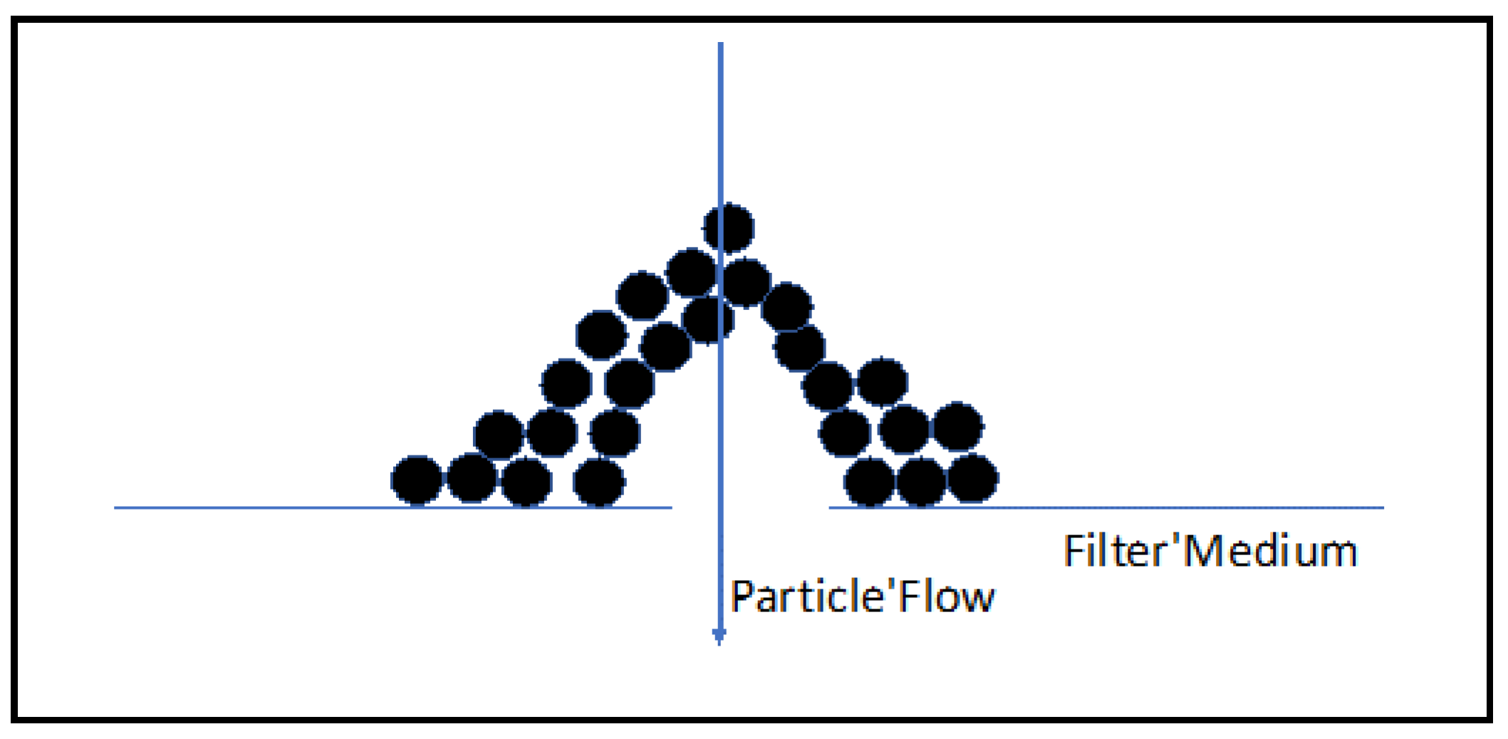
There are four different mechanisms of particle separation that take place using a rigid barrier filter and are categorized into either (1) straining or (2) filtration.

2.1.1. Straining

Straining (surface filtration) works primarily by surface interception, and thus depends on the relative difference in the particle size and filter pores. Straining can be further divided into (a) surface straining and (b) depth straining. Surface straining occurs when the diameter of the filter pores is smaller than the particles being filtered, inhibiting them from passing through the filter pores. Depth straining is where a particle encounters a cone-shaped pore. The particle is small enough to pass through the outer pore area but eventually gets caught inside the pores as the inner pore diameter decreases to smaller than that of the particle [47].

2.1.2. Filtration

Filtration is different from straining wherein particle separation is not directly related to the relative size difference between the particles and filter. During filtration (cake or depth), five fundamental forces cause the particles to come in contact with the ceramic wall or barrier: diffusion, inertial impaction, interception, electrostatic attraction, and gravitational settling [10,47,48]. Filtration can be further classified into (a) cake filtration and (b) depth filtration. In cake filtration, particles are built up on the outer surface of the filter forming a cake. This cake then becomes the primary method of separating the particles without allowing them to penetrate into the pores of the filter. Depth filtration on the other hand takes place when the particle adheres to the inner wall of a pore even though the diameter of the particle is smaller than the pore. [47].

2.2. Formation of Filter Cake and Associated Problems

Particulate buildup on the surface of the filter leads to the development of a cake, which is instrumental in the further separation of PM. These cakes ensure sufficient filtration efficiency (defined as the ratio of filtered particles to total input particles) over a range of particle sizes at a range of velocities and are a vital part of the design of the filter [10,47,49]. Cake filtration is particularly useful for separating dust particles as these typically are the smallest of the PM (diameter 1–5 µm) [50]. The filter cake, however, leads to increased pressure drop [10]. The balance that must be struck in the design of the filters is with regard to the pore sizes. The smaller the pore size, the more efficient the separation of particles. However, smaller pore size leads to faster cake buildup and thus increased pressure drop (along with an initial higher pressure drop). On the contrary, if pore sizes are increased, there will be slower cake build up and less pressure drop but the separation of particles will be less efficient. The other factor at play is the mechanism of depth filtration. Often depth filtration leads to an exponential increase in pressure drop and as the pores become blocked, cake filtration takes over causing the pressure drop to increase linearly as more particles are accumulated [15,51].
Another phenomenon that can lead to the development of filter cakes is bridging [52]. This occurs when the particles are smaller than the pores but the pores can still be blocked by accumulated particles “bridging” the gap over a pore entrance and/or cross-sectional throat area [53] as illustrated in Figure 1. Bridging is caused by softening and sintering of dust in the PM, leading to an increase in the cohesion and adhesion forces at elevated temperatures. These forces cause the dust to stick to one another and the filter medium and eventually encompass the pore opening. Problems resulting from bridging include unstable filtration and increased tensile stress on the filter medium. As the filter cake steadily builds up on the bridge, the pressure drop increases thus requiring the regeneration of the filter. Further issues from bridging result during the regeneration of the filter including incomplete regeneration and even damage or breakage of the filter itself [16].

2.3. Regeneration Techniques to Control Cake Buildup

2.3.1. Back Pulsing

There are several different types of regeneration techniques to reduce/eliminate filter cakes and the resulting pressure drop. For filters such as baghouses, mechanical shaking is performed as these flexible materials cannot handle the high mechanical stress of compressed gas pulses at high temperatures, which is required for adequate regeneration of most rigid filters [23,48,54]. Techniques for rigid filter cleaning include conventional jet pulsing, venturi ejector jet pulsing, and coupled pressure pulsing. Jet pulsing techniques require pressures of 0.5–1 MPa higher than or double the operating pressure of the filtration unit, while the coupled pressure pulse has the advantage of only requiring an additional 0.05–0.1 MPa of pressure [23,32,55], suggesting coupled pressure pulsing to be a preferred regeneration technique depending on the type of filter and application.

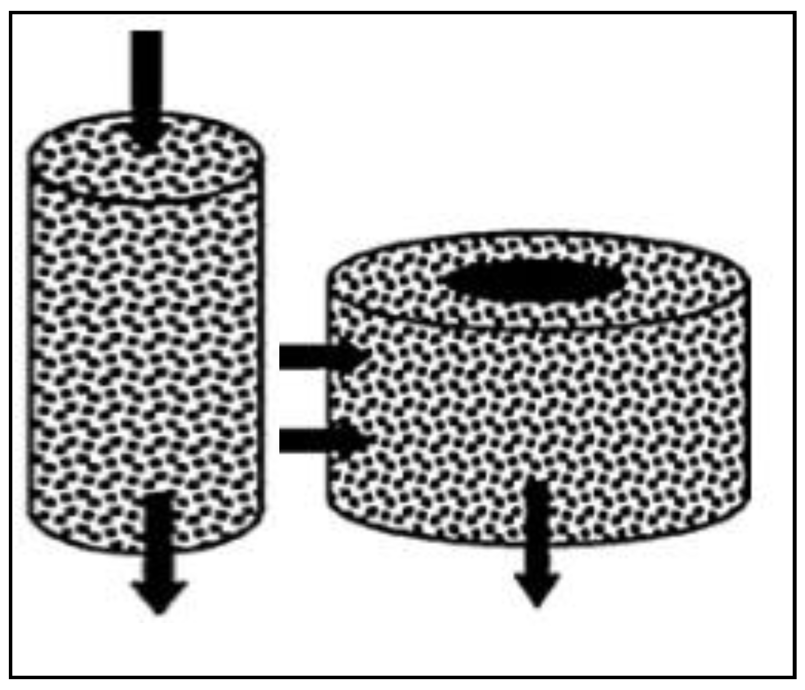
2.3.2. Design Configurations

In addition to back pulsing for removal of filter cake, several filter designs/configurations have been developed that allow for either reduction in pressure and/or frequency of back pulsing in rigid filters. One such design configuration is crossflow filtration wherein the raw gas flows axially along the inside of the filter element with filtration occurring radially through the walls. Turbulence caused by the axial flow results in shear forces that dislodge dust (cake) buildup on the filter surface, providing both advantages and disadvantages. Advantages include reduced pressure drop and thus a reduced requirement for back pulsing regeneration. Disadvantages include concerns regarding plugging of the filter when high dust content enters the filter element [56]. Traditional types of crossflow ceramic filters are subject to distortion or delamination over time due to the hot gas exposure and the fact they are composed of several parts fastened together. Demolding of the body of the assembly causes the inner walls of the filter to crack due to prolonged heat exposure. Modern versions of crossflow filters are cast from a single mold, which will extend the lifetimes of the filters and avoid these shortcomings [57].
Other types of ceramic filters used in plants are the tube and the candle. The tube-type filter design (invented by Asahi Glass Co. Ltd., Tokyo, Japan and Mitsubishi Heavy Industry Ltd., Tokyo, Japan) has an open configuration (open at both ends) and uses the inner surface to effectively filter particulates [56]. While some of these tube filters have been used with great success as they can be less prone to breakage from the decreased likelihood of dust bridging between tubes [23], others have seen breakages and dust leaks as a result of inadequate tube sealing [56]. Additionally, these tube filters have been known to require additional pressures of 1.5 MPa or higher over the operating pressure for back pulsing due to heavy cake buildup [13]. The most common and preferred type of filter is the ceramic candle. Within this filter category, the popular inverted candle design was developed by Schumacher, Siemens-Westinghouse, LLB, and Pall [56]. These candles are open at one end and closed at the other and oriented such that particulate-laden gases flow through the inner side of the tube, while the cake build-up is on the outer surface of the candle, which allows the clean gases to flow along the hollow center [58]. These candles can be up to 3 m long with normal outer diameters of 6–15 cm and are arranged in metal arrays of several hundred supported by a plenum [16,23]. The arrangement of the filter arrays is important, especially in horizontally arranged filter tubes, to allow the settlement of dust down and away through the bottom of the filter vessel. This is to not induce further collection of blown-back dust from regeneration and to prevent it from settling on bottom-oriented filter tubes and thus being subjected to further dust bridging [23]. Proper orientation of these arrays allows for very efficient and continuous use of the ceramic filters, which is beneficial for PM separation and thus this design finds application in many industries.
In summary, the pore size distribution of the filter is a critical parameter in designing the filters. The size and uniformity of the pores can have a major effect on the filtration efficiency and pressure drop across the filter media. The choice of the pore size when designing a filter is dependent on the particulate size and distribution. Pressure drop across filters resulting from cake buildup can be controlled by incorporating various regeneration techniques, which have their own advantages and disadvantages. Advances in filter technology over time have produced materials with a thin fine-pore grain layer membrane on the outside of the filter that avoids the problems of depth filtration and bridging while also maintaining a low-pressure drop and stable regeneration [23]. With the advances in material characteristics as well as improvements that have been made with regard to geometrical design, arrangement, and operation, ceramic filters have become essential in numerous high-temperature particulate filtration applications.

3. Common Industrial Filtration Applications

Ceramic materials can be used as a filter for particulate removal in any process that requires hot gas filtration. Examples include separating PM in engine exhausts in the automotive industry and filtering volatile grease in the food industry for the aforementioned synthesis gas cleanup [15]. The filtration capabilities of ceramic filters have had an enormous impact on other energy industries such as waste incineration, coal and biomass conversion, fluid catalytic cracking in refineries [16], and its original use in nuclear power plants for radioactive waste incineration [55,59]. In addition, ceramic filters have been seen in multiple high-temperature processing industries including the production of metals, metal oxide powders, glass, catalysts, and pigments [23]. The most common industrial use of ceramic filters, more recently, has been in the conversion of coal, biomass, and other carbonaceous waste products for energy production such as power, chemicals, fuels, and green hydrogen. In such applications, filters are used to separate particulates to avoid damage to downstream process equipment. Integrated gasification combined cycle (IGCC) plants typically use coal to generate electricity; however, biomass is used as feedstock in similar IGCC plants. Steam turbines and other equipment downstream of the gasifier in these plants have the potential of being damaged by PM, which is a component of syngas produced during the gasification process. To minimize PM entering downstream processing equipment, a ceramic filter is often placed between the gasifier and the turbine [13]. The following subsections provide details of the use of ceramic filters for particulate removal applications in the energy sector with an emphasis on using biomass and waste carbonaceous materials as feedstock. The use of ceramic filters for particulate removal in thermal conversion industries including combustion, gasification, pyrolysis, and incineration processes is discussed herein.

3.1. Biomass Conversion

One of the earliest uses of ceramic filters was in the application of downstream particulate filtration for the conversion of coal for power/electricity generation. As it is well known, coal is one of the most energy-dense feedstocks and has been used for centuries to produce power. Turbines downstream of a gasifier or incinerator are highly susceptible to erosion and other issues due to the presence of PM in the feed gas. Therefore, ceramic filter units have been utilized to prevent downstream equipment damage. Filter units have been heavily applied in the demonstration of pressurized fluidized bed combustion (PFBC) combined cycle and currently exist in more than 25 IGCC plants across the globe [23]. One such system is in place at a 300 MWe IGCC coal gasification plant in Puertollano, Spain where the filter unit contains two arrays each housing 1036 ceramic candle filters. 90% of hot gas filtration units in IGCC applications use ceramic SiC candle filters; however, a few metal media have also proven to be successful including Inconel 600, Monel, and Hastelloy X. For applications with high hydrogen sulfide content, specific iron aluminide alloys are used [16].
Systems solely dedicated to biomass conversion have also taken advantage of the benefits that ceramic filter units have to offer. The use of biomass for energy generation can present problems as it has a higher alkali and halogen content than coal, which can cause corrosion and fouling of equipment such as turbine blades [7]. However, despite the issues caused by the presence of chlorine and alkali compounds, there has been a big push in the conversion of biomass due to it being a renewable energy resource, possessing a lower ash content than coal, having high abundance around the world, and the fact that it is a waste product [60]. Biomass gasification in particular has been gaining popularity and is considered one of the most promising thermochemical routes for converting biomass to energy and clean hydrogen. Gasification is the partial oxidation of carbonaceous fuels at high temperatures (>700 °C) to produce synthesis gas (syngas), which is primarily composed of hydrogen and carbon monoxide. Part of the popularity surrounding gasification is a result of the versatility of the products that can be produced from syngas. Syngas has a variety of applicable uses including combustion for combined heat and power, generation of electricity, and use as a feedstock to produce transportation fuels and general/specialty chemicals, such as hydrogen. However, downstream syngas applications require contaminants in syngas to be below certain concentrations depending on the particular application in order to process effectively (Table 2).
Two syngas contaminants that present major hurdles limiting biomass gasification commercialization are PM and tar. Tar formation is the most cost-inducing problem and will be covered later, however, PM is most effectively separated through high-temperature barrier filtration using metallic or ceramic materials. Ceramic candle filters have been proven to be effective in the filtration of PM that is present in the producer gas exiting the gasifier or other biomass conversion reactors. An advantage of these filters is the relatively stable pressure drop brought about by the blowback pulse while maintaining efficiencies >99% (particle diameters <2.5 µm) [7,62]. Another advantage particularly applied to biomass conversion is the filter’s high resistance to erosion and corrosion, which as stated earlier, is especially problematic due to the high alkali levels inherent to the feedstock.
Traditionally, ceramic filters are placed downstream of the gasifier and upstream of a tar reforming unit and operated between 350–600 °C [63]; however, in recent years, the operating temperature has increased to 800–850 °C in order to match the gasifier outlet and tar reformer inlet to increase thermal efficiency [64]. The downside of increasing the temperature is that this also leads to an increased pressure drop across the filter unit [65]. Fluidized beds have been a popular design for gasifier reactors as they can ensure relatively even mixing of bed material, biomass, and gasifying agents, such as carbon dioxide, steam, oxygen, air, or a mix. Turn, et al. [9] used a fluidized bed reactor for the gasification of Bana grass, where they employed a ceramic filter as well as a sorbent bed getter, which is sometimes used for further removal of PM, specifically alkali compounds and chlorine. Sulfur removal is a high priority due to its tendency to poison downstream catalysts [18,29].
Studies such as one by Kurkela, et al. [65] used a circulating fluidized bed gasifier where they employed a cyclone in order to aid in the reduction of PM and to recirculate the bed material. In their study, they converted bark mixtures, forest residues, and wood pellets through steam-oxygen gasification. Over the course of a 215 h test, the filter unit containing ceramic candles was able to remove almost all PM (below the detection limit of 5 mg/nm3) and alkali metals and reduced the inlet chlorine content by 90%. Additionally, the pressure drop was maintained at a baseline of 1.0–1.2 kPa.
Several researchers [66,67,68,69] performed studies as a part of the CHRISGAS project, which utilizes a 100 KWth circulating fluidized bed gasifier located at Delft University of Technology in The Netherlands. Simeone, et al. [67] tested woody fuels including miscanthus, which has been known for its high ash content. The filter vessel contained three 1520 mm long SiC candle filters possessing a mullite membrane. Varying face velocities from 3–5 cm/s (1–5 cm/s is the typical range for ceramic filters) were tested for 50 h of operation. PM mostly consists of bed material and ash built up to 4 kPa in one hour requires a novel type of coupled pressure pulse regeneration strategy. In a later study on the project, Simeone, et al. [66] tested a ceramic candle filter array at 800 °C and were able to maintain a stable pressure drop of 14–16 kPa over 12 h with intermittent pulse regeneration (blow back pressure of 300 kPa every 10–15 min) capable of lowering the pressure by 2 kPa. These ceramic filters are highly resistant to acoustic and vibrational loads, which makes them flexible during pulse blowbacks.
The use of ceramic filters for particulate removal Is not limited to biomass gasification but has been employed in pyrolysis processes as well. Pyrolysis is another thermochemical conversion route for green hydrogen production. Pyrolysis coupled with steam reforming is a promising alternative for selective green hydrogen production, however, is in the developmental phase (TRL 3.5–4.0) [70,71]. Kang, et al. [72] utilized three cylindrical ceramic filters downstream of a cyclone in the fast pyrolysis of Radiata pine in a bench-scale fluidized bed. The system was equipped with a cyclone responsible for separating particles >10 µm downstream of which the hot filter unit operated at 400 °C separated the finer particles around 1 µm in size. Based on the composition of the char, it is clear that secondary reactions occurred in the filter converting the char into smaller chain hydrocarbons. Although there is limited literature on the use of ceramic filters in pyrolysis applications for particulate removal, there appears to be a promising potential especially as the technology matures for green hydrogen production.

3.2. Mixed Feedstock Conversion

Ceramic filter systems have also been utilized in gasification facilities using mixed feedstock [73,74]. De Jong, et al. [74] used a blend of coal, miscanthus, and wood to achieve carbon conversions of over 80%. In this study, a ceramic filter unit was placed downstream of a fluidized bed gasifier equipped with a cyclone in a 50 KWth test rig. The filter unit comprised of SiC-type candle filters (Schumacher) operated at 500 °C and was effective in separating ash and unconverted carbon material in the flue gas. In a parallel experiment by De Jong, et al. [74] a channel-type honeycomb or crossflow ceramic filter was used in a 1.5 MWth test rig equipped with a pressurized fluidized bed gasifier employing the same mix of coal and biomass feedstock. Operating at 650–700 °C, a pressure drop between 1.0 and 1.6 kPa was observed across the crossflow filter unit. These studies using mixed fossil fuel and biomass feedstocks have been performed as part of the push toward renewable energy.

3.3. Municipal Solid Waste (MSW) and Hazardous Waste (HW) Conversion

The use of ceramic filters as applied to pyrolysis and other thermal conversion methods has also been used when combusting municipal solid waste (MSW) as feedstock. MSW is a mix of waste products that, in the U.S., are typically broken down by the following components (w/w): paper and cardboard at 25.0%, food waste at 15.2%, plastics at 13.2%, yard trimmings at 13.1%, with the remainder being a mixture of glass, metals, wood, rubber, leather, textiles, and other miscellaneous inorganic wastes [75]. The mixed feedstock often gives rise to some processing problems in the form of heat and mass transfer limitations during conversion. Another problem that is seen while using MSW is the variable moisture content leading to inconsistent calorific value and the non-uniform nature of the feedstock [76]. The use of MSW as a feedstock takes advantage of the fact that it is a waste product that otherwise would be disposed of in a landfill where it causes leaching and other environmental problems, such as the release of methane gas [77]. The conversion of MSW typically takes place in the form of incineration for electricity generation. In these applications, there is a host of PM present in the flue gas that must be removed prior to emission. Traditionally, MSW incineration facilities have made use of fabric filters housed in a baghouse to separate PM [78]. The flow regime is designed around the baghouse since the fabric filters start to degrade at high temperatures (>300 °C) [6]. Therefore, the gases must be cooled (quenched) before they come in contact with the baghouse filter unit leading to efficiencies losses. Before the baghouse, electrostatic precipitators were sometimes used to capture finer particles; however, these are less effective than fabric filters for collecting PM in the submicron (0.1–1.0 μm) range and are not well studied at elevated temperatures (>680 °C) [79,80]. Fabric filters operate in much the same way as ceramic candle filters by building up a dust cake on the surface of the woven fibers; however, this temperature limitation is a shortcoming of the material. Using a ceramic filter in this process instead could lead to increased efficiency with the ability to operate at a higher temperature without the risk of damaging equipment and possible process shutdown [81].
The use of a ceramic filter unit for incineration purposes has been tested at Wythenshawe Hospital in Manchester, England where 400 kg/day of clinical waste is used as the feedstock [82]. Clinical waste from biomedical applications is a valuable feedstock due to its high energy content and volatility [6]. This filter unit contains 64 filter candles and operates at an average pressure drop of 2.3 kPa, a face velocity of 1.3 cm/s, and a temperature of 200 °C. The reason for this low temperature is due to the filter unit being placed downstream of the economizer, which uses much of the heat to create steam through the boiler to generate power [78].
One of the disadvantages of MSW incineration and incineration of other waste materials is the potential formation of dioxins and furans, which needs to be effectively treated before the flue gases are released [6]. There are also difficulties with high-temperature operation where inorganics entering the gas phase are liable to damage the filter. This requires sturdier filters for long-term use and thus has a higher capital investment. Gasification is also a common conversion method that utilizes MSW as feedstock and like biomass gasification, syngas is the resulting product [83]. Additionally, pyrolysis has been gaining popularity in recent years for the many uses of the oil and gas that are produced from the process [84].
Several MSW pyrolysis facilities have integrated ceramic filtration for particulate removal in their processes. The Pyropleq process utilizes low-temperature pyrolysis technology and was implemented at a 550 kWe plant in Burgau, Germany that processes 20,000 tons of MSW per year. This process has a high dust removal rate and it utilizes both a ceramic filter system and a baghouse within its operations [85]. There is another pyrolysis plant that uses a rotary pyrolysis kiln and hot gas filter unit with a capacity of 126 tons of MSW per day in Hokkaido, Japan. The filter unit at the Hokkaido plant contains 600, 3 m long ceramic candle filters each having a usable area of 1.40 m2 [82,84]. At the Hokkaido plant, the filter unit is situated downstream of the kiln and upstream of the combustion chamber. The candle filters were tested over a period of 150 h operating at a face velocity of around 2 cm/s and a temperature of 300 °C. They were able to keep the PM concentration below 0.4 mg/m3 while maintaining a pressure drop of 3 kPa [84]. These low-density ceramic candle filters have been proven to meet the demands of an MSW pyrolysis plant where filter operations can be difficult given the low temperatures. If the temperature is too low, there can be condensation risks associated with potential unit disruption.
There is a growing market for high-energy pyrolysis oil for the generation of electricity, transportation fuels, and/or production of specialty chemicals [86] He, et al. [87] used a fixed bed design containing a calcined dolomite catalyst to obtain oil and syngas from MSW pyrolysis. The dolomite catalyst within the fixed bed was set in a stainless steel tube between porous ceramic discs. The pyrolysis gas encountered the ceramic discs, which serve as the residual tar reforming unit. Then, downstream along the process, the gas enters a cyclone, which eliminates the larger particulates followed by a fiber wool filter that separates out the finer particles. This design configuration appeared to perform well under the conditions tested.
Despite the advances that have been made in the MSW pyrolysis realm there exists the issue of how to efficiently deal with the leftover solid residue (char) that still contains a fair amount of carbon. In order to make use of the energy content within the char there must be a method to effectively convert it through a treatment method preferably on-site [76]. There have been studies looking into using the char for a variety of purposes such as a coal replacement as “biochar” and even as a catalyst or catalyst support for tar reforming [88]. Another potential option is to use the char to produce carbon nanomaterials (CNM) as there have already been studies using biomass residues and MSW as feedstocks for the process [89]. Current CNM manufacturing involves chemical vapor deposition and flame synthesis techniques, both of which are energy-intensive and use expensive ethylene, carbon monoxide, and hydrogen feedstocks; thus, chemicals that are already produced through MSW pyrolysis. Another obstacle encountered with MSW pyrolysis is the soot contamination of catalyst substrates [61]. To overcome this obstacle, ceramic barrier filters are used along with steam injection or soot blowing [85]. The trend so far with MSW and other material conversions is the removal of PM as an impurity to achieve more efficient processing; however, a more important problem is the issue of tar formation.

4. Ceramic as Catalyst Support

In addition to PM removal applications, ceramics have also successfully been used in catalyst substrate applications. This entails using ceramic materials as a support for catalyst particles. Desirable properties of catalyst support include:
  • High surface area and porosity,
  • Ability to maintain mechanical integrity at the elevated temperatures required for reaction, and
  • Uniform pore size and structure for selectivity of product.
Ceramic materials possess all these qualities, making them ideal catalyst supports. One example of using ceramics as catalyst support was reported in a study by Hwang, et al. [41] where Ni and Pt catalysts were impregnated on a CeO2 ceramic filter for use in the water-gas shift reaction (WGSR). An early use of ceramics in reaction engineering was the advent of ceramic membranes, which would often be made out of γ-Al2O3 and would involve sol-gel synthesis [66,90,91]. These γ-Al2O3 ceramic membranes have been used for applications such as the dehydration of 1-butanol [92], converting methanol to olefins [93], hydrogen production through water association [94], and dry reforming of fermentation products for syngas production [95]. However, the most common catalytic applications for ceramic supports have been in the area of pollution control, such as tar reforming, NOx reduction, and VOC oxidation.
Many of the processes that require the conversion of contaminants including tar reforming, NOx reduction, and VOC oxidation also require the removal of particulate matter from their respective gas streams. As a result, an evolution emerged whereby the application of ceramics is not limited to just particulate removal or catalyst applications functions, but takes on the dual role of both particulate removal and catalyst applications in the same unit. The properties that the ceramic catalyst support possesses also lend the material to the separation of PM at high temperatures, as discussed earlier. This results in process intensification, wherein both these operations are performed simultaneously in one unit. Although the emphasis of this article is on biomass syngas cleanup to produce green hydrogen, owing to limited literature related to the hot gas cleanup of syngas, this literature review has been expanded to include applications that potentially involve particulate removal and catalytic conversion processes including NOx reduction and VOC oxidation. Although, not directly relevant to syngas cleanup, this additional information will aid in the development of integrated hot gas cleanup of biomass syngas. The following sections will discuss and provide pertinent information related to the use of ceramic media as catalyst support for NOx reduction and VOC oxidation applications.

4.1. Reduction and Oxidation of Pollutants

4.1.1. Nitrogen Oxides (NOx) Reduction

One category of pollutants that are prevalent in many combustion processes is nitrogen oxides consisting of NO, N2O, and NO2 as the main constituents and are commonly known as NOx. Many attribute the source of NOx to combustion and other fuel-burning processes, but it is also an emission in many industries including agriculture, and waste disposal [45]. However, it is true that the main sources of NOx are automobiles, power plant boilers, incinerators, petroleum refineries, biomass conversion plants, and manufacturing plants, including cement, glass, iron, and steel production. In addition to NOx causing respiratory diseases in humans, it also has an adverse impact on the environment; wherein, it is a major cause of acid rain, leads to the formation of photochemical smog, and is a contributor to the formation of ground-level ozone, which can heavily damage ecosystems [96].
As a result of the damaging effects of NOx, researchers have performed extensive studies focusing on limiting their emissions. Several studies have evaluated the use of ceramic materials as catalyst support for NOx reduction, the details of which are presented in Table S1 in Supplementary Materials. NOx compounds are reduced to N2 in a process commonly referred to as selective catalytic reduction (SCR). Popular SCR catalysts for NOx conversion lately have been vanadium and tungsten oxides supported on a titanium oxide film in a combination seen as V2O5-WO3/TiO2. This combination of catalysts coated on a catalytic filter support has been especially successful in catalyzing the reaction of NOx with NH3, which is used as a reducing agent, as seen in Equations (1) and (2) below [60]:
4 NO + 4 NH 3 + O 2 4 N 2 + 6 H 2 O
2 NO 2 + 4 NH 3 + O 2 3 N 2 + 6 H 2 O
The role of V2O5 in the reaction is to increase the number of Brønsted and Lewis acid sites thus increasing the overall surface acidity activity and selectivity toward N2. WO3 promotes Lewis acid sites to increase NH3 adsorption and inhibit the sintering of the TiO2 film in which it is dispersed [45]. V2O5 can also promote the unwanted oxidation of adsorbed NH3 to form NOx at elevated temperatures [60]. Döring, et al. [62] found that 300 °C is the optimal catalyst operating temperature for NOx conversion to N2 while avoiding these undesired NH3 oxidation side reactions.
The concept of using ceramic filter material for both filtration and catalytic reduction of NOx is novel and relatively new (early 2000s). Therefore, the majority of the studies presented in Table S1 have tested impregnated ceramic filter supports for SCR purposes only in dust-free conditions to optimize catalytic and operating conditions before continuing on to simultaneous SCR and filtration [63,64,65,67,68,69,72,73,74,75,76,77,78]. Phule, et al. [65] performed a set of experiments to examine various impregnation methods and determine optimal catalyst loading for NOx reduction. V2O5-WO3/TiO2 was coated on a SiC ceramic filter cylinder via novel rotational coating methods that were developed in an attempt to achieve deeper catalyst pore impregnation. At a NOx and NH3 concentration of 700 ppm, the catalyst was able to achieve nearly 100% NOx conversion in the optimal temperature range of 230–350 °C, which agreed with the aforementioned optimal temperature of 300 °C [62,65]. The optimal catalyst loading was determined to be 10 wt% with the best composition containing 3 wt% V2O5. Increasing vanadium content led to unwanted increased NH3 oxidation yielding greater N2O formation.

4.1.2. Volatile Organic Compounds (VOCs) Oxidation

Volatile organic compounds (VOCs) are another pollutant that has been of particular focus to researchers. Along with NOx, VOCs are also responsible for ground-level ozone production and can cause health issues. Additionally, VOCs are often emitted with NOx and SOx from mobile sources such as in the automotive industry, and also from stationary sources such as industrial boilers, power production, and the architectural industry. The classification of VOCs includes anything that contains carbon, has a high vapor pressure at room temperature, and usually but not necessarily causes negative health effects [79]. They can take the form of ringed carbons such as naphthalene but can also be shorter chained compounds such as propane or propene [80]. Chlorinated VOCs can also be formed through a number of mechanisms and these have a host of health hazards but can be oxidized to form HCl, which can be removed through adsorption [29]. It is sometimes economical for VOCs present in low concentration in flue gas to be adsorbed; however, this may require frequent regeneration of the adsorbent and depending on the VOC components may be difficult due to rapid desorption and thus VOC oxidation is the preferable route [80]. Hence, VOCs have been added to the list of pollutants that researchers are attempting to remove within a single unit using catalytic ceramic filters to further increase process efficiency and reduce costs [60,77,81,82,83,84]. The typical design for this process application is illustrated in Figure 2 [81].
Preliminary experiments using catalytic ceramic filters were performed solely to study the removal of VOCs before introducing other pollutants. Saracco, et al. [85] studied VOC oxidation over γ-Al2O3 coated on an α-Al2O3 ceramic filter impregnated with 5 wt% Pt. VOC oxidation has been well studied using platinum catalysts as they are highly active; however, high cost has led to research toward cheaper catalysts, such as V2O5 and WO3 [80]. Influent gas consisted primarily of He with the following additional concentrations: naphthalene at 50 ppmv, propylene, propane, and methane all at 5000 ppmv, and finally, O2 at 18 vol%. These VOCs were chosen for their representation of different classes of VOC compounds: PAHs, alkanes, alkenes, and knock-resistant methane, which are commonly found in fuels. At space velocities in the range of 5–65 Nm3 m−2 h−1, the highest pressure drop obtained was under 1.8 kPa. 90% conversion was achieved for naphthalene, propylene, propane, and methane at temperatures of 180 °C, 300 °C, 400 °C, and 480 °C, respectively. Models that were developed and then compared to the experimental data showed decent agreement with these conversions [85].
There have also been investigations into the removal of VOC and NOx using a catalytic ceramic filter. Zürcher, et al. [77] studied the SCR of NO and VOC oxidation, using propene as a model compound over V2O5-WO3/TiO2 impregnated on a mullite ceramic foam filter. Two different reactor orientations were tested, a tubular reactor was used for axial flow experiments and a ring-shaped reactor was used for radial flow experiments as shown in Figure 3 [77]. In the inlet, 500 ppm of NH3 and NOx each was fed along with 3% O2 in an N2 gas matrix with propene at 300 ppm also added. Tested reaction temperatures ranged from 150 to 320 °C with the modified residence times ranging from 0.02 to 0.05 g-s/cm3. Results showed increasing NOx and propene conversion rates reaching nearly 100% at 300 °C for axial flow. Radial flows showed systematically lower conversions for both reactions, which was due to the backflow mixing caused by the greater cross-sectional area of the ring compared to the relatively shorter length of reactor as confirmed by residence time distribution measurements.

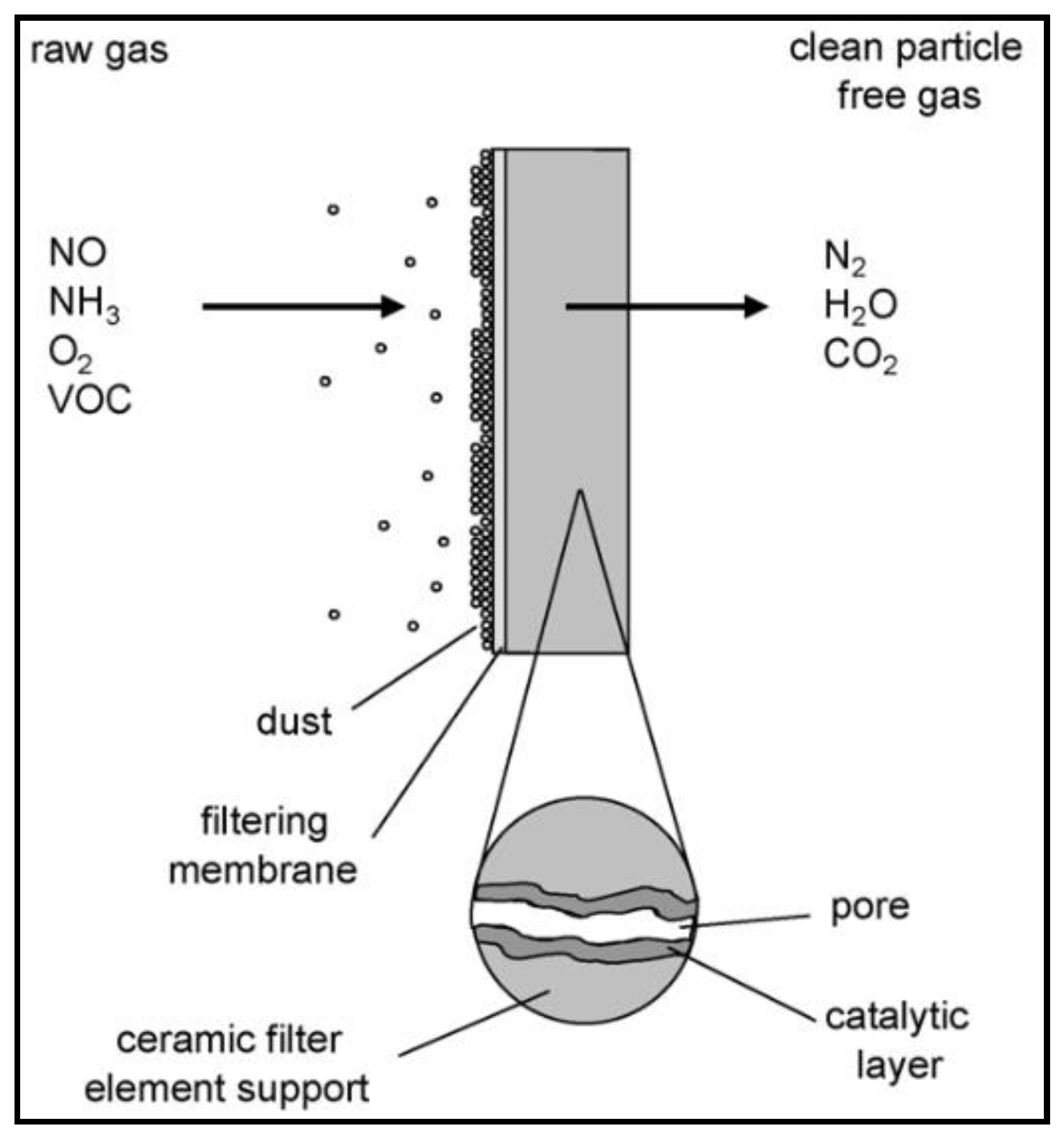
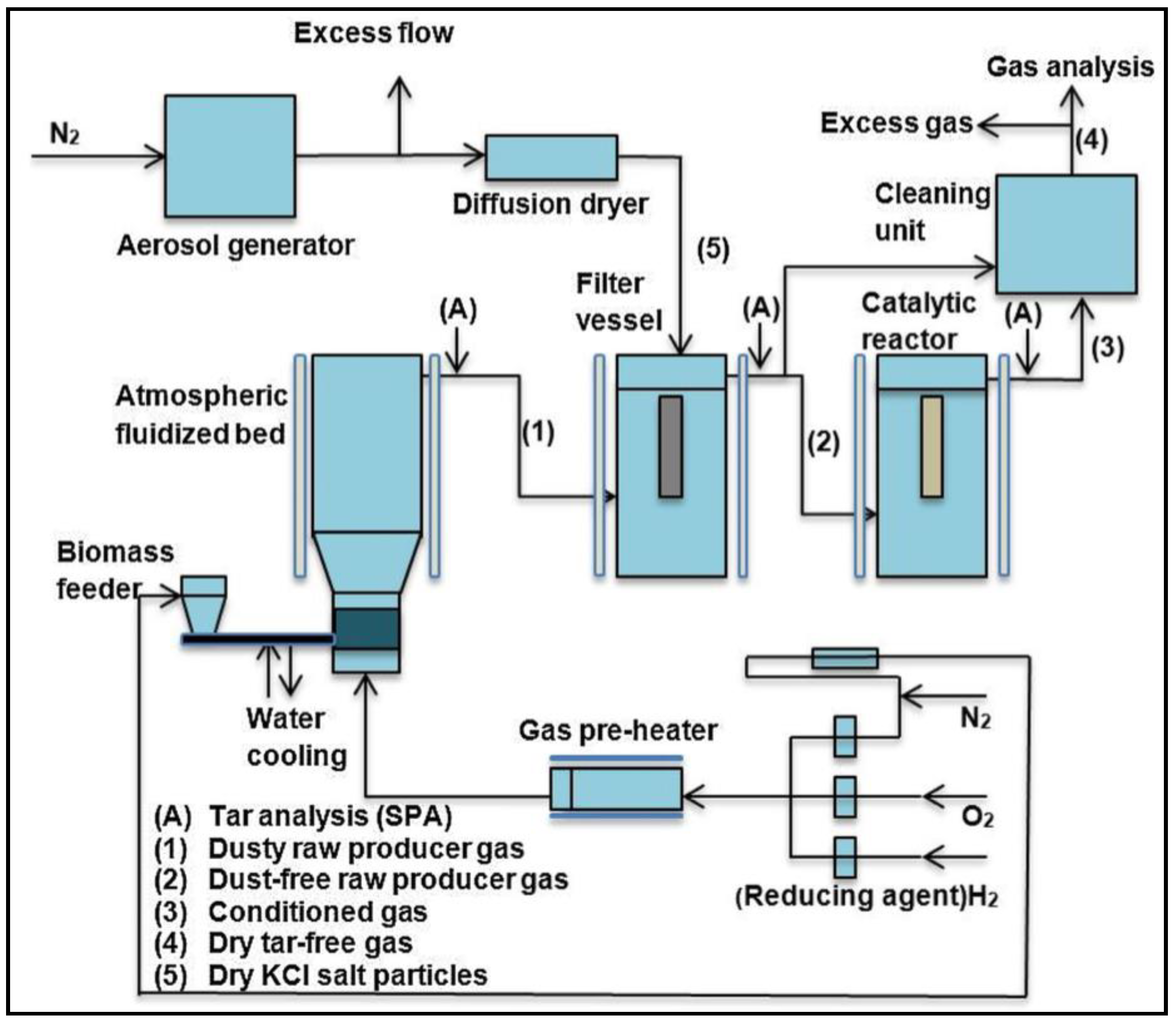
4.1.3. Integrated Catalytic Reduction/Oxidation and Filtration

As discussed in previous sections, the majority of the work has focused on using ceramics as catalyst support for catalytic reduction and oxidation of various environmental pollutants. However, limited information is available on the use of ceramic filters for both PM removal and catalytic oxidation/reduction of chemical species. In process intensification applications, the ceramic filter support is impregnated with an SCR catalyst in order to achieve both the filtration and NOx reduction functions in one step. In industrial processes, this process intensification will reduce the number of process units and lower installation and operating costs [86]. Due to the relative novelty of this concept, there are many studies still in the preliminary stages of investigation taking a systematic approach and most of the studies related to catalytic reduction have been discussed earlier. Although limited, there have been many studies as shown in Table S1 focusing on using ceramic filter materials to separate the particulates while simultaneously reducing NOx compounds to produce N2 in a process known as selective catalytic reduction (SCR).
Studies involving process intensification by way of the utilization of ceramic filters impregnated with SCR catalyst have also been performed on the pilot scale using actual emissions from commercialized processes rather than using the simulated gas inputs. In actual emissions, there are other contaminants that must be processed to meet emission standards. A byproduct present in power plant flue gas emissions and other industrial plants are sulfur oxides or SOx, which predominantly come in the form of SO2. These compounds lead to the formation of sulfate aerosols, which cause damage to vegetation as well as forest and water ecosystems. Additionally, SOx and sulfate aerosols can cause respiratory problems when airborne and through absorption in the bloodstream by the consumption of dissolved species in drinking water [87]. SO2 as well as the contaminant HCl, which can lead to the formation of dioxins and other hazardous air pollutants, are traditionally removed via oxidation or using adsorbents, such as lime [29]. Oxidation of SO2 forms SO3, which reacts with the ammonia that is present to reduce NOx and water, which is present in flue gas (10–30%), to form ammonium sulfate/bisulfate deposits [45]. At temperatures <300 °C, it will deactivate catalysts but at elevated temperatures, it has proven to increase Brønsted acidity by increasing adsorption on NH3 and thus increasing NO removal efficiency [67].
The elimination of these pollutants including PM in a single unit presents further process intensification that would allow for even greater capital cost reduction rather than having separate units for each pollutant. Choi, et al. [86] tested the removal of NOx, SOx, HCl, and PM on the pilot scale using one-meter-long fibrous ceramic candle filters impregnated with CuO/Al2O3, V2O5/TiO2, and V2O5/TiO2/SiO2-Al2O3, separately. The input gas of NO, SO2, and HCl was in the range of 1000–2000 ppm with NH3/NO, SO2/lime, and HCl/lime molar ratios all in the 1-1.2 range, while the dust loading was tested at two levels: 40 and 100 g/m3. The tests were performed at 300–350 °C with a space velocity of 1900–6600 h−1. Test results at optimal conditions showed PM, NOx, SOx, and HCl removal efficiencies of 99.5%, 90%, 75%, and 50%, respectively, over a two-month period. When the candle filters were treated for just PM and NOx, they were able to achieve 90% NO conversion with a loading of 1000 ppm at 350 °C, space velocities of 1900–6600 h−1, and NH3/NO of 1.1. When the untreated ceramic candle filters were tested for the removal of only particulates they were able to hold 99.5% removal efficiencies and stable pressure drop for 16 months, which meets the minimum commercial requirement of 10,000 h [87,88].
Another pilot-scale system was tested using a 3 m long ceramic catalytic filter tube to filter flue gas from a 200 kW coal-fired boiler in a study by Tan, et al. [89]. The filter tube was made of aluminosilicate fibers (81 wt% Al2SiO5) and contained V2O5, WO3, TiO2 at 1.56, 1.13, and 3.75 wt%, respectively. The inlet gas conditions consisted of NOx, SO2, HCl, and dust in concentrations of 130 μL/L, 1200 μL/L, 1200 μL/L, and 30 g/m3, respectively, with operating conditions set to a temperature range of 260–380 °C with a face velocity of 1.67 cm/s. Denitrification efficiencies close to 100% were observed at elevated temperatures (>350 °C) and around 95% at lower temperatures (<350 °C). Calcium hydroxide and sodium carbonate/bicarbonate injections were performed to achieve the removal of SO2, and HCl at efficiencies of 90 and 97%, respectively, with a Na/S ratio of 3.0 and 85% and 91%, respectively, with a Ca/S ratio of 2.0. Meanwhile, filtration efficiencies of 99.99% were observed with pressure drops in the range of 1.0–1.4 kPa with blow-back regeneration pulse pressures of 600 Pa used every 40 ms.

4.1.4. NOx Reduction Simulations and Recent Advances

In order to better understand the effects of the SCR of NOx over a catalytic ceramic filter, several researchers have performed simulations to test model agreement with experimental data [64,77,97]. Novel simulations were carried out by Nahavandi, et al. [97] using the electrohydrodynamic (EHD)-SCR technique to enhance the SCR of NOx via NH3 over a V2O5/TiO2 impregnated hollow ceramic reactive tube. The EHD method has been used to enhance heat transfer for various electric, heat, and flow field applications including refrigerant condensation along the tubes of a heat exchanger, nucleate boiling, and bubble dynamics involved in boiling heat transfer. In this study, the EHD technique was simulated by an electrode (connected to an anode) running along the core of the hollow cylinder while a metal sheet (connected to a cathode) covered the outside of the cylinder and potential was created. The hypothesis was that the system would allow enhanced utilization of the catalyst through enhanced heat transfer. EHD force, transport, and kinetic equations were developed and parameters were set using data from the SCR data from literature and governing equations were solved using Comsol Multiphysics. The filter was assumed to have a porosity of 64–82.5 vol% with a V2O5 loading of 1–3.45 wt%. Operating conditions included temperatures of 100–200 °C, gas hourly space velocity (GHSV) of 10,000–20,000 h−1, and NO/NH3 at a concentration of 350 ppm. Non-EHD simulations were conducted in an effort to validate predictive models with experimental data from catalytic filter candle studies and the results showed excellent agreement (1% maximum average deviation) at GHSV = 11,000 h−1 with 7.6 vol% O2. These findings confirmed Eley–Rideal kinetics as the dominating mechanism involved in the NO reduction with a strong adsorption of NH3 on the catalyst surface [98]. For the EHD studies, the potential range was 0–300 V and results showed an overactive use of the catalyst at lower temperatures leading to elevated NO conversions whereby at 100 V there was 100% NOx conversion at 180 °C and a GHSV = 10,000 h−1. Interestingly enough, NOx conversion started to decline around 180 V due to flow acceleration caused by the increased potential leading to lower residence times and ultimately a concentration gradient due to the mass-transport effects. Overall, the EHD technique had an enhancing effect on the catalyst leading to a 75% increase in NOx conversion [97].

4.2. Tar Reforming

Gasification of biomass produces syngas contains tars, as mentioned earlier. Tars result from partially converted feedstock in thermochemical processes and present a major problem because they condense in cold spots thus creating blockages and fouling in downstream processing equipment [40]. Tars are defined as polynuclear aromatic hydrocarbons (PAHs) having molecular weights equal to or higher than that of benzene (78 amu). Making up the bulk of tar composition are benzene, toluene, other one-ring aromatic compounds, and naphthalene with the balance consisting of higher molecular weight compounds [99]. Most of these compounds are also carcinogens that impose a health risk if released into the environment [5]. Tar content ranges from 5–75 g/m3 in most syngas depending on the feedstock, gasifier type, operating conditions, etc. [100,101]. Relative to the input, using an updraft gasifier typically leads to 10–20 wt% tar content, whereas using a more efficient downdraft or fluidized bed gasifier leads to a 0.1% tar content [102]. Other sources have observed tar content from updraft, fluidized bed, and downdraft gasifiers of 100 g/Nm3, 10 g/Nm3, and 1 g/Nm3, respectively [6]. Tars present the most difficult obstacle in gasification since they must be reduced by 99.9% on average in order for the syngas to be useful. Table 2 shows contaminant tolerance limits for various downstream syngas applications [10,61]. In addition to the problems tars cause within the process, they also limit the efficiency of the overall gasification process. Tars can potentially be converted to syngas constituents if reformed, which increases the energy density of syngas while not wasting carbon energetic potential. An increase in cold gas efficiencies of up to 25% are possible depending on the tar levels [103].
Tar removal in general is classified into two categories; cold gas cleanup (<200 °C) and hot gas cleanup (>200 °C). Cold gas cleanup mostly consists of physical tar removal methods. Physical methods include wet scrubbing, which typically is performed in the 50 °C–60 °C range and have tar removal efficiencies of 50–90%, which can also remove upwards of 95% of the PM >5 μm [10,104]. The downside of this strategy is that there is no energy recovered from the tar since it is merely transferred from one phase (gas) to another (liquid). Moreover, there is the downside of needing to dispose of the wastewater stream generated from this process. Hot gas cleanup techniques include both thermal and catalytic. Thermal cracking is an option, which, in essence, is the combustion of tars at very high temperatures (1100–1300 °C). This strategy encourages soot production and may only reduce tars by up to 80% [10]. This may be sufficient for some end-use applications; however, more effective methods of tar removal may be necessary depending on the end-use applications such as ethanol synthesis [10].
The most promising strategy appears to be catalytic tar removal, which operates at high temperatures (550–950 °C) and has achieved greater than 99% tar removal [105]. Tar reforming catalysts operate via two main tar reforming endothermic reactions, steam, and dry reforming, as shown in Equations (3) and (4), respectively [106,107,108,109,110].
C n H m + nH 2 O nCO + ( n + m / 2 ) H 2   Δ H 298 , C 10 H 8 = 1161   kJ / mol
C n H m + nCO 2 2 nCO + m / 2 H 2   Δ H 298 , C 10 H 8 = 1570   kJ / mol
There are other reactions that occur during gasification such as WGSR, reverse WGSR, methane reforming, and Boudouard reactions [111]. Certain catalysts are effective at cracking tars into syngas, which improves the efficiency of the overall gasification process [112]. Catalysts for tar removal are typically classified into synthetic and mineral. The mineral catalysts include ferrous metal oxides, clay minerals, olivine, and calcined rocks [113]. Amongst these are dolomites, which can achieve up to 95% tar conversion but are very soft and fragile and can be eroded in fluidized bed reactors [114,115]. Synthetic catalysts include transition metal-based, activated alumina, alkali metal carbonates, fluidized catalytic cracking (FCC) catalysts, and char. A particular interest under the category of transition metal-based catalysts are Ni-based catalysts [113]. Ni-based catalysts have shown to be effective in reducing greater than 99% of tar content, are particularly reactive in cracking of aromatics, are widely available, and are cheaper than other effective transition metal catalysts such as Rh, Pt, and Ru [40,116]. When Ni is supported on a support such as an alumina or a zeolite, its mechanical strength is improved and it is protected in extreme environments such as at high temperatures or where there is a possible risk of attrition [111,113,117]. Ni has proven to be is an efficient catalyst for steam reforming of tars, however, like other catalysts it is prone to coking [118]. Coking occurs when carbon is deposited on active Ni sites over the course of the tar reforming reactions, leading to the deactivation of these sites and resulting in decreased tar removal efficiencies [119]. With increasing temperatures, the rate of carbon deposition on the surface of the catalyst increases faster than the removal rate, however, the deposition rate can be reduced by increasing the steam/carbon ratio [54,120]. At lower temperatures (>300 °C), carbon deposition increases through diffusion and mainly involves the formation of whisker carbon through reactions (5) and (6) [121]. At temperatures of >600 °C and high pressures, deposition through carbon precursors on the catalyst takes place causing the formation of pyrolytic carbon via Reaction (7) after a series of reaction leading to this reaction occur as detailed below [122].
CO C ( s ) + CO 2
CO + H 2 C ( s ) + H 2 O
C n H 2 n nC ( s ) + H 2
Coking can occur by chemisorption, which entails the formation of a reacted carbon monolayer over the catalyst’s active sites or by physisorption, which entails multilayers of adsorbed carbon that also block the surface sites. Carbon that is deposited initially has a more reactive amorphous structure but, over time and as temperature increases, these structures give way to more stable graphitic structures. Tar formation can also plug pores thus blocking access to the inner pore surface area and active sites within [123]. Promoters such as Mg, Ca, and K can be used to help decrease coking by lowering acidic strength [124]; however, decreased acidity leads to lower tar conversion so a balance must be struck [111,125]. This strategy was used by Moud, et al. [126] who investigated tar, alkali, and sulfur-laden syngas. Tar reforming was performed using Ni with a K promoter. The setup (shown in Figure 4 [126]) used a 5 kW atmospheric bubbling fluidized gasifier and a hot gas ceramic filter downstream of the gasifier to separate PM. A fixed bed catalytic reactor was located downstream of the ceramic filter for tar removal, which resulted in nearly 100% tar conversion over a period of 36 h of performance time on the process stream.
The setup with the hot gas filter upstream of the catalytic tar reformer has been shown to be advantageous with the hot gas filtration eliminating some of the tar content, therefore, relieving some of the stress resting upon the tar reformer [88,127]. Simeone, et al. [88] tested a ceramic candle filter array in a study that investigated the gasification of biomass in a 100 kWth atmospheric circulating fluidized bed. A stable pressure drop of 14–16 kPa was maintained over 12 h with intermittent pulse regeneration (blow back pressure of 300 kPa every 10–15 min). As a result of the high temperatures and gas residence times in the filter unit, the candle filters were effective in breaking down higher molecular weight tars such as pyrene into lower molecular weight tars, such as naphthalene, as well as boosting H2 production by 10%. The potential of a filter to act as a pre-reformer for tars has also been seen by Tuomi, et al. [127] whereby a ceramic filter operating at 690–715 °C was able to reduce 50 wt% of total tars entering the filter unit. This was believed to be achieved in part by unreacted biomass char as well as dolomite bed material eluting from the fluidized bed gasifier, which accumulated, forming a sticky cake on the ceramic surface and acting as a catalyst [127]. It has been proven that the most promising and cost-effective strategy for tar abatement is catalytic tar reforming whereby the conversion of tars into syngas improves the overall efficiency of the gasification process. In the above studies, it is shown that a filter upstream of the catalytic tar reformer increases tar reforming efficiency.
The next logical step is to combine the hot gas filter unit and the tar reforming unit into one. This way, process intensification can be achieved by reforming tars and filtering particulates in a single unit thus increasing efficiency and cutting capital/operating costs while reducing space. With regard to biomass gasification, the combination of filter unit with tar reforming results in a major process intensification step that is illustrated in Figure 5. Normally, biomass enters the gasifier and is converted into syngas accompanied by tar and particulate impurities. This stream of tar- and particulate-laden syngas then enters a cyclone to remove most of the PM. The stream then flows through a filter to remove the remainder of the particulates. The particulate-free, tar-laden gas stream then enters a tar reformer where tar is converted into syngas. Tar- and PM-free clean syngas is then utilized in various end-use applications. In the process intensified process, after the tar and particulate-laden syngas exits the cyclone, syngas flows through a catalytic ceramic filter unit. In this unit, the remaining particulates are removed, while tars are reformed. Clean syngas exits this catalytic ceramic filter reactor, which is used in its designed end-use applications. Practically, this is achieved by using a ceramic filter as a catalyst support.
The concept of impregnating catalyst particles onto a porous ceramic for the purposes of tar reforming has been investigated. The next step is to use a catalyst support (non-powder) whose material is the same ceramic that is used in hot gas filtration. The topic of impregnating catalysts on ceramic filters for use of the dual effect of particulate filtration and tar reforming has been seen in several studies [38,128,129,130,131,132,133,134]. The following describes the application of catalytic filter units and their role in the process where raw syngas will encounter a ceramic candle and first will filter the PM by the use of a fine membrane coating the outside of the candle or by the actual surface of the candle itself. This will cause a PM cake to buildup on the outside of the candle but tar molecules will penetrate the membrane and outer surface of the candle into the inner pore structure. These inner pores have catalysts dispersed onto their surface area, which will reform tars to produce more syngas. Reformed clean syngas then flows to the inner hollow core of the candle and onto the next processing unit. This process is depicted in Figure 6. Studies investigating the process intensification concept when applied to biomass gasification through in-situ and ex-situ catalysis arrangements are discussed herein.

4.2.1. In-Situ Tar Reforming

The method of in-situ catalysis when applied to tar reforming involves placing the catalyst within the same unit where gasification takes place. Often this is done through the use of primary catalysts where catalyst materials are blended with fluidized bed material or used as fluidized bed material themselves [135]. This is a common strategy to control tars before they exit the gasifier. It has been demonstrated that filtration and tar reforming can both be performed in-situ whereby catalytic ceramic filters are placed within the gasifier, which allows gasification, particulate filtration, and tar reforming to take place all in one unit [136]. In the UNIQUE gasification configuration, catalytic candle filters are strategically placed within the freeboard section of a fluidized bed gasifier [137,138,139,140,141,142,143,144,145,146,147,148,149,150,151,152,153]. This arrangement is shown in Figure 7 [137]. The advantage of in-situ catalysis is the ability to perform all three major process functions, gasification, particulate filtration, and tar reforming in one reactor, which will allow savings on capital costs and system space requirements while increasing thermal efficiency [154]. This compact design concept avoids the need for cooling, which is where complications involving tar condensation are most likely to occur.
The UNIQUE configuration was demonstrated by Savuto, et al. [152]. Candle filters were filled with nickel catalyst pellets and placed in the freeboard section in a bench-scale fluidized bed gasifier for hot gas cleaning while performing gasification of almond shells at 800 °C. The candle that was partially filled (75% w/w) with catalyst had a pressure drop of 3.5 kPa (same as the empty candle filter) and was capable of reducing the tar concentration from 3 g/Nm3 to 250 mg/Nm3 (92% conversion) at a GHSV of 5678 h−1. The candle filter that was filled to the maximum holding capacity with catalyst had a pressure drop of 5.5 kPa and was capable of reducing the tar concentration from 3 g/Nm3 to 390 mg/Nm3 at a GHSV of 4126 h−1. The reduced efficiency of the fully filled candle may have been due to a preferential gas flow path along the top of the candle filter in order to avoid resistance at the bottom. The filtration velocity was 2.8 cm/s for the tests and no appreciable pressure drop increase was observed over the course of the experiments; however, the longest test was conducted with a time on stream of only 240 min. Another study [150] looked into the gasification of almond shells at 810 °C using Al2O3 filter candles with a MgO-Al2O3 (70/30 wt%) suspension impregnated with 47 wt% NiO via incipient wetness impregnation. These candles filters, with an outer diameter (OD) of 60 mm, an inner diameter (ID) of 40 mm, and a length of 456 mm (effective filtration length of 394 mm), were loaded one at a time for each experiment into the freeboard of a 0.1 m ID fluidized bed gasifier. From the blank test, the tar concentration decreased from 3.67 g/Nm3 to 1.47 g/Nm3 at a filtration velocity of 1.9 cm/s over the course of 189 min. Steadily increasing pressure drops over the course of the experiment were observed with the candle filter starting out at 1.7 kPa at the beginning then quickly jumping up to 2.25 kPa and ending around 3.4 kPa [150]. Normally there are regular blowback pulses to expel the built-up filter cake on the candle filters in order to maintain a steady pressure drop, however, this was not performed in the above studies. Pulsing, if implemented or performed under this configuration, would potentially result in operational problems within the bed owing to difficulties maintaining steady state fluidity and conversion. It has been posited that if an empty volume is incorporated into the core of the candle filter then these back pulses should be feasible; however, this has not been tested [152]. In addition to potential pressure drop problems, another potential drawback of using this configuration/strategy is possible entrainment of the bed material leading to ceramic candle filter damage by attrition. There are advantages to the in-situ catalytic configuration/strategy; however, when it comes to practical implementation, several operational challenges exist and it may be extremely difficult to maintain the intended tar removal efficiencies. Due to the operational challenges, very few studies were performed using in-situ filtration and having varying results in terms of tar conversion. In one pilot scale study where both filtration and tar reforming are performed using catalytic ceramic filter candles, Rapagná, et al. [140] was only able to obtain a tar conversion of 58% over a test period of 60 min in the gasification of almond shells. This low efficiency is thought to have been a result of catalyst poisoning via H2S in the producer gas. Additionally, as a result of depositing nickel catalyst particles to the filter candles the pressure drop increased in a pre-gasification test from 0.78 kPa to 2.38 kPa at 25 °C, and 2.5 cm/s. Due to this 3-fold increase in pressure drop in low temperature preliminary testing, it was decided to decrease the nickel content in order to decrease the pressure drop. This may explain the low tar conversion over the test period.

4.2.2. Ex-Situ Tar Reforming

The method of ex-situ catalysis when applied to tar reforming is when the catalytic ceramic filters are placed in a secondary reforming unit downstream of the gasifier [136]. In this manner, particulate filtration and tar reforming are both performed within a single unit. The ex-situ configuration/strategy has been evaluated using various ceramic filter supports that differed in geometry such as discs, candles, and monoliths. In addition, different ceramic structures were tested, such as foams, which varied in their characteristics and compositions. Further, tests were done using a number of catalysts under a wide range of operating conditions (Table S2), however, a majority of the testing was done using nickel-based catalyst formulations.

Ceramic Discs

The most common filter geometry evaluated for tar removal was the filter disc support, which was impregnated with various catalyst formulations [155,156,157,158,159,160,161,162,163,164,165,166]. Discs were used as a way of modeling the use of candle filters on a laboratory scale [110,165]. Most of these studies used a tar simulant molecule such as naphthalene as a tar model compound since it is one of the most stable molecules present in tar [111]. Tests were performed using various catalyst formulations and loadings and at a range of operating conditions with varying velocities, S/C ratios, and temperatures, which yielded tar-free gas streams under optimal conditions. One such tar steam reforming study was performed using an α-alumina ceramic filter disc of a diameter of 3 cm, thickness of 1 cm, and impregnated at a Ni loading of 1 wt% using the urea precipitation-deposition method [157]. Using naphthalene as a model compound in biomass gasification representative outlet gases, it was shown that at 900 °C, nearly 100% naphthalene removal was achieved at a velocity of 2.5 cm/s. These excellent findings give hope for the future of incorporating a catalytic filter unit into a biomass gasification process. It should be noted that almost all of the discussed bench-scale studies investigate and attempt to optimize tar reforming, however simultaneous removal of PM has not been investigated. Preliminary studies will eventually work up to using actual gasifier exhaust gas with all the PM and byproducts in their experiments. Another aspect of the preliminary studies is using a disc to replicate the wall of the eventual filter candle that will be tested in the scaled-up investigation.

Ceramic Monolith

Another ceramic geometry that was discussed in the diesel emission control section is the ceramic monolith. The monolith design leads to lower pressure drops and possesses a large external surface area as compared to its volume, two characteristic advantages in heterogeneous catalysis [167,168]. In addition to diesel emission applications, these have been popular as catalyst supports for tar reforming and filtration [168,169,170,171,172]. In a study by Rhyner, et al. [169], a noble metal catalyst is impregnated on a 400 cpsi ceramic monolith for steam reforming of PAHs in representative biomass gasifier output in the presence of sulfur compounds, which have been known to poison catalysts such as Ni, Fe, Cu, and Co. The catalyst was tested in the temperature range of 620–750 °C at GHSV of 9000 h−1 and 18,000 h−1. Tar conversion was higher in fuel gas that was sulfur free, lower GHSV, lower steam content, and higher temperature. After achieving a toluene conversion of only 47% in sulfur-laden input gas it was concluded that a greater catalyst loading was needed in order to obtain lower tar concentrations. Ceramic monoliths have been used in other non-tar reforming applications. For example, Ni was impregnated on CeO2 ceramic monoliths for the purpose of oxy-steam reforming of biogas [173].

Ceramic Foams

In addition to ceramic supports differing in geometry, they also come in a variety of different core structures. One popular structure used are ceramic foam supports, which are typically made of α-Al2O3, ZrO2, or CeO2 [39,40,174,175,176]. These materials have characteristic open pores giving them very high porosity (>90%). These foams with a reticulated structure and typically are shaped into disc or cylindrical geometries [166]. These foams have garnered specific interest as catalyst supports due to their pores creating a tortuous flow path as well as low resistance to fluid flow [177]. The foams described here are of the open-cell variety, which typically have pore densities of 10–100 pores per square inch and have interconnecting porosity. These characteristics lead to lower pressure drop in packed beds, improved mass transport, and relatively higher surface areas and effectiveness factors [178,179].
It is these characteristics that make foams interesting as a material for catalytic filtration purposes. Gao, et al. [38,39,40,134,174,175] investigated hydrogen production using impregnated ceramic foams for reforming various samples including coal tar, benzene, biomass pyrolysis oil, and actual biomass tar from a gasifier. In one of the studies, Ni was impregnated on ceramic foam shaped into cylinders to optimize hydrogen output from the steam reforming of the tar model compound benzene [40]. The ceramic foam was 38 mm in diameter with a length of 50 mm and was composed of 79.24% Al2O3, 19.29% P2O5, 0.77% SiO2 and impregnated with Ni at a loading of 3.50 wt% via the deposition/precipitation method, however possessing a surface area of only 3 m2/g. Operating conditions used were temperatures of 700–900 °C, S/C of 0.0–3.0, equivalence ratio (ER) of 0.0–0.4, and WHSV of 5.6 h−1, with each test lasting 30 min. At 750 °C, S/C of 1.0, and ER of 0.1, there was an increase in H2 production from 22.38 to 177.62 g H2/kg of benzene, an increase in carbon conversion from 44.15 to 77.03%, and an increase in H2/CO molar output from 0.67 to 2.21 compared to the blank foam. These results confirm the ability of the catalyst to transfer oxygen as well as the activity of foam in adsorbing steam to induce gasification reactions. Additionally, CO/CO2 molar output and carbon conversion were shown to increase with temperature. H2/CO molar output showed a decreasing trend relative to increasing temperature and ER. This can be explained by the inhibition of the WGSR to produce hydrogen. Kinetic studies performed showed an activation energy of 73.38 kJ/mol and a frequency factor of 1.18 × 10⁵ m3 kg −1 catalyst h−1. Ceramic foams have been used in other non-tar reforming applications. For example, Ni and Pt were impregnated on CeO2-ZrO2 foams with a SiC carrier for the application of bioethanol steam reforming [180].

4.2.3. Ceramic Support Summary

The different ceramic supports presented have their own advantages and disadvantages depending on the application in question. The high porosity of the reticulated ceramic foams is a major advantage with regard to filtration as it will lead to a reduced pressure drop in actual processing operations. The open-cell format with low tortuosity that the foam structure possesses leads to better flow and higher rates of reactant-wall collisions leading to higher residence times [121]. This design leads the ceramic foams to be good tar-reforming catalyst supports as this will lead to low sintering of the catalyst. Since tar reforming operates at high temperatures there can be a tendency for the metal catalyst particles to agglomerate. This agglomeration reduces the available active site surface area and increases the likelihood of carbon deposition [121]. The disadvantage of the foams in addition to monolith structures is that they tend to have a very low surface area (<4m2/g) leaving a limited amount of space for catalyst particles. To combat this, a coating or wash coat is applied to increase the available surface area and active sites [166]. The advantages that discs have over monoliths, however, are in their uniformity of radial mass transport. Although both monoliths and discs possess superior radial heat transfer, monoliths are limited in their radial mass transport capacity as a result of their checkerboard layout. Discs have good radial mass and heat transport that gives an even concentration distribution. When a foam-structured disc is used, it has the advantage of having an evenly distributed gas flow owing to the superb radial mass and heat transport as a result of the open-cell format [181]. This is an important factor when it comes to tar reforming and catalysis in general.

4.2.4. Tar Reforming Filter Simulations

Tar reforming simulations including both in-situ and ex-situ methods have been performed in several studies in order to test agreement between theoretical models and experimental outcomes [14,179,182,183]. In a study by Rhyner, et al. [179], kinetic parameters including activation energies and frequency factors were determined by performing 149 experiments in order to accrue tar reforming kinetic data of different hot gas filter designs in a range of operating conditions. The heterogeneous reaction kinetics were assumed to be pseudo first order in a one-dimensional model and took into account internal and external mass transfer limitations. Filter designs include the monolith and foam cylinder, which were mounted in the vertical and horizontal orientation or candle filters as shown in Figure 8 [179]. Vertical simulations were tested with 5 candles of length 2.0 m and the horizontal with 20 candles of length 0.5 m with all gas filtration velocities maintained at 2.6 cm/s. It was determined that a catalytic active layer of 1.26 m2 and an operating temperature of 850 °C were needed to keep outlet sulfur concentration under 0.1 ppmv. The Ergun Equation shows that a 400 cpsi and a 100 cpsi monolith induced a pressure drop of 2.6 kPa and 0.9 kPa, respectively. The results show that tars were more easily converted in a sulfur-free environment, which agreed with experimental results [169]. Additionally, the conversions of tars including toluene, naphthalene, phenanthrene, and pyrene showed good agreement with the experiments (<10% deviation). However, high flow rates showed greater disagreement with predicted values. This could be due to the model underestimating catalyst activity at high conversions and overestimating activity at low conversions due to the very wide range of observed conversions from experimental results.

5. Conclusions and Future Perspectives

In this review, a discussion is presented on the use of traditional uses of porous ceramics in industrial processes as well as more recent advances and potential use opportunities. In general, ceramics are well-suited for high-temperature applications and are in the process of replacing metals in these applications in order to save on costs. Specifically, porous ceramics have been proven to be advantageous as a material used as catalyst support and a filter. More recently they have been process intensified for use in supporting both mechanisms in one unit. The high mechanical strength of the ceramic with tunable pore sizes makes it an invaluable material for separating small-diameter PM at high temperatures. This is a necessary task in processes across several industries. Additionally, the low pressure drop achievable by ceramics makes it especially useful in downstream processing from reactors.
The high-temperature resistance of ceramics has led them to be studied as a catalyst support. The ceramic catalyst support has most commonly been used in NOx reduction, VOC oxidation, and tar reforming. The use of this support for simultaneous catalytic and filtration applications has been reviewed extensively. Ceramic candle filters on a large scale have been used in many industries to filter PM and are now under investigation as catalyst support. To study the effectiveness of this move toward process intensification, many studies have experimented with different types of ceramic supports on the lab scale. Different geometries and structures have been tested including discs, monoliths, and foams, which give their own set of advantages and disadvantages depending on the application. Further, different unit operation orientations of ceramic catalyst supports have been discussed in order to shine a light on the benefits and downfalls of in-situ and ex-situ tar reforming. However, very limited information is available that evaluated the process intensification concept for hot gas removal/cleanup of both tars and particulates using one unit.
Process intensification by means of the combination of filter units and catalytic reactors for the conversion of unwanted byproducts is very promising for cost savings on a commercialized level. However, challenges still exist on the road to the optimization of these integrated processes. One such challenge is with regard to the filter material properties. All of the ceramic filters discussed in the review possess material properties of high mechanical strength, low coefficient of thermal expansion, and high corrosion resistance, and allow minimal pressure drop, flexibility to blowback regeneration, and overall adequate separation of particulates for sufficient time on stream. The material obstacle exists in the low surface area of these filter materials for proper catalyst coverage. Most of the studies showed ceramic filters possessing surface areas of <4 m2/g. In order to meet the demands required for proper downstream application and emission standards, the catalyst support materials need to boast surface areas comparable to those of commercial catalyst supports such as zeolites, which can possess surface areas >1000 m2/g. There has been some success in adding a wash coat to the ceramic to increase the surface area [166].
Another challenge that is seen in the process intensification step of impregnating ceramic filters with catalysts for tar reforming is the increased pressure drop that occurs as a result. It has been observed that by depositing catalyst particles on the ceramic filter support there is a gain in pressure drop across the catalytic filter unit [130,140,152]. This is likely due to a decrease in the porosity as catalyst particles block ceramic pores. This may lead to even further pressure drop increases as carbon deposition takes place. In order to combat this, less catalyst can be used, however, this may compromise the tar reforming advantage [140]. To maintain tar conversions, it is necessary to develop impregnation techniques that inhibit catalyst particle agglomeration keeping particle sizes low and dispersed. Additionally, it would be advantageous to develop porous ceramics that contain larger pores while also boasting a high surface area.
Excellent opportunity and potential exist for integrated catalytic hot gas cleanup of gas streams to eliminate contaminants in various applications including combustion, gasification, and incineration. Further, there is a promising potential for the use of these integrated systems in pyrolysis systems for both gas cleanup and upgrading of pyrolysis vapors to produce various chemicals and fuels including hydrogen.

Supplementary Materials

The following supporting information can be downloaded at: https://www.mdpi.com/article/10.3390/en16052334/s1, Table S1: Studies on ceramic catalyst filters for NOx reduction; Table S2: Studies on ceramic catalyst filters for tar reforming.

Author Contributions

Conceptualization, P.B. and M.Z.; resources, P.B.; writing—original draft preparation, D.P.; writing—review and editing, D.P., P.B., D.G., R.H., J.G.; supervision, P.B., J.G.; project administration, P.B., M.Z., R.H.; funding acquisition, P.B., M.Z. All authors have read and agreed to the published version of the manuscript.

Funding

This work was funded by the Energy Institute of Louisiana and Louisiana Board of Regents Support Fund (BoRSF) Endowed Professorship in Bioprocessing with the University of Louisiana.

Data Availability Statement

Data sharing not applicable.

Conflicts of Interest

The authors declare no conflict of interst.

Abbreviations

CNMcarbon nanomaterials
CPSIcells per square inch
DPFdiesel particulate filter
IGCCintegrated gasification combined cycle
MSWmunicipal solid waste
NOxnitrogen oxides
PAHpolycyclic aromatic hydrocarbon
PFBCpressurized fluidized bed combustion
PMparticulate matter
SOFCsolid oxide fuel cells
SCRselective catalytic reduction
SOxsulfur oxides
VOCvolatile organic compound

References

  1. Department of Energy. Biden-Harris Administration Announces Historic $7 Billion Funding Opportunity to Jump-Start America’s Clean Hydrogen Economy; Department of Energy, Ed.; Department of Energy: Washington, DC, USA, 2022.
  2. Ochu, E.; Braverman, S.; Smith, G.; Friedman, J. Hydrogen Fact Sheet: Production of Low-Carbon Hydrogen; Columbia University: New York, NY, USA, 2021. [Google Scholar]
  3. Ruth, M. Hydrogen Production Cost Estimate Using Biomass Gasification: Independent Review; National Renewable Energy Laboratory: Golden, CO, USA, 2011.
  4. Alptekin, F.M.; Celiktas, M.S. Review on Catalytic Biomass Gasification for Hydrogen Production as a Sustainable Energy Form and Social, Technological, Economic, Environmental, and Political Analysis of Catalysts. ACS Omega 2022, 7, 24918–24941. [Google Scholar] [CrossRef] [PubMed]
  5. Bridgewater, A.V. The technical and economic feasibility of biomass gasification for power generation. Fuel 1995, 74, 631–653. [Google Scholar] [CrossRef]
  6. Milne, T.A.; Abatzoglou, N.; Evans, R.J. Biomass Gasifier “Tars”: Their Nature, Formation, and Conversion; NREL/TP-570-25357; National Renewable Energy Laboratory: Golden, CO, USA, 1998.
  7. Dayton, D. A Review of the Literature on Catalytic Biomass Tar Destruction; National Renewable Energy Laboratory: Golden, CO, USA, 2002.
  8. Biomass Conversion: Challenges for Federal Research and Commercialization; Report Published by Biomass Research and Development Board; Biomass Research and Development Board: Golden, CO, USA, 2011.
  9. Turn, S.Q.; Kinoshita, C.M.; Ishimura, D.M.; Hiraki, T.T.; Zhou, J.; Masutani, S.M. An Experimental Investigation of Alkali Removal from Biomass Producer Gas Using a Fixed Bed of Solid Sorbent. Ind. Eng. Chem. Res. 2001, 40, 1960–1967. [Google Scholar] [CrossRef]
  10. Woolcock, P.J.; Brown, R.C. A review of cleaning technologies for biomass-derived syngas. Biomass Bioenergy 2013, 52, 54–84. [Google Scholar] [CrossRef]
  11. Lind, T.; Hokkinen, J.; Jokiniemi, J.K.; Saarikoski, S.; Hillamo, R. Electrostatic Precipitator Collection Efficiency and Trace Element Emissions from Co-Combustion of Biomass and Recovered Fuel in Fluidized-Bed Combustion. Environ. Sci. Technol. 2003, 37, 2842–2846. [Google Scholar] [CrossRef]
  12. Aravind, P.V.; de Jong, W. Evaluation of high temperature gas cleaning options for biomass gasification product gas for Solid Oxide Fuel Cells. Prog. Energy Combust. Sci. 2012, 38, 737–764. [Google Scholar] [CrossRef]
  13. Sharma, S.D.; Dolan, M.; Park, D.; Morpeth, L.; Ilyushechkin, A.; McLennan, K.; Harris, D.J.; Thambimuthu, K.V. A critical review of syngas cleaning technologies—Fundamental limitations and practical problems. Powder Technol. 2008, 180, 115–121. [Google Scholar] [CrossRef]
  14. Rhyner, U. Reactive Hot Gas Filter for Biomass Gasification. Ph.D. Thesis, ETH Zurich, Zurich, Switzerland, 2013. [Google Scholar] [CrossRef]
  15. Mertzis, D.; Koufodimos, G.; Kavvadas, I.; Samaras, Z. Applying modern automotive technology on small scale gasification systems for CHP production: A compact hot gas filtration system. Biomass Bioenergy 2017, 101, 9–20. [Google Scholar] [CrossRef]
  16. Heidenreich, S. Hot gas filtration—A review. Fuel 2013, 104, 83–94. [Google Scholar] [CrossRef]
  17. Corporation, P. Gas Filtration Intro; Pall Corporation: Port Washington, NY, USA, 2008. [Google Scholar]
  18. Ding, W.; Shi, Y.; Kessel, F.; Koch, D.; Bauer, T. Characterization of corrosion resistance of C/C–SiC composite in molten chloride mixture MgCl2/NaCl/KCl at 700 °C. npj Mater. Degrad. 2019, 3, 42. [Google Scholar] [CrossRef] [Green Version]
  19. Jha, S.; Sekellick, R.S.; Rubow, K.L. Sintered Metal Hot Gas Filters. In Proceedings of the 4th International Symposium Gas Cleaning at High Temperatures, Karlsruhe, Germany, 22–24 September 1999. [Google Scholar]
  20. Adler, J. Ceramic Diesel Particulate Filters. Int. J. Appl. Ceram. Technol. 2005, 2, 429–439. [Google Scholar] [CrossRef]
  21. Heidenreich, S. Ceramic membranes: High filtration area packing densities improve membrane performance. Filtr. Sep. 2011, 48, 25–27. [Google Scholar] [CrossRef]
  22. Cummer, K.; Brown, R. Ancillary equipment for biomass gasification. Biomass Bioenergy 2002, 23, 113–128. [Google Scholar] [CrossRef]
  23. Heidenreich, S. Chapter Eleven—Hot Gas Filters. In Progress in Filtration and Separation; Tarleton, S., Ed.; Academic Press: Oxford, UK, 2015; pp. 499–525. [Google Scholar] [CrossRef]
  24. Gómez-Martín, A.; Orihuela, M.P.; Becerra, J.A.; Martínez-Fernández, J.; Ramírez-Rico, J. Permeability and mechanical integrity of porous biomorphic SiC ceramics for application as hot-gas filters. Mater. Des. 2016, 107, 450–460. [Google Scholar] [CrossRef]
  25. Roewer, G.; Herzog, U.; Trommer, K.; Müller, E.; Frühauf, S. Silicon Carbide—A Survey of Synthetic Approaches, Properties and Applications. In High Performance Non-Oxide Ceramics I; Jansen, M., Ed.; Springer Berlin Heidelberg: Berlin/Heidelberg, Germany, 2002; pp. 59–135. [Google Scholar]
  26. Schaafhausen, S.; Yazhenskikh, E.; Heidenreich, S.; Müller, M. Corrosion of silicon carbide hot gas filter candles in gasification environment. J. Eur. Ceram. Soc. 2014, 34, 575–588. [Google Scholar] [CrossRef]
  27. Schaafhausen, S.; Yazhenskikh, E.; Walch, A.; Heidenreich, S.; Müller, M. Corrosion of alumina and mullite hot gas filter candles in gasification environment. J. Eur. Ceram. Soc. 2013, 33, 3301–3312. [Google Scholar] [CrossRef]
  28. Yalamaç, E.; Trapani, A.; Akkurt, S. Sintering and microstructural investigation of gamma–alpha alumina powders. Eng. Sci. Technol. Int. J. 2014, 17, 2–7. [Google Scholar] [CrossRef] [Green Version]
  29. Environmental, U. Characterisation and Estimation of Dioxin and Furan Emissions from Waste Incineration Facilities; UNILABS: Sydney, Australia, 2001; p. 93. [Google Scholar]
  30. Fukushima, M.; Yoshizawa, Y.-i. Fabrication and morphology control of highly porous mullite thermal insulators prepared by gelation freezing route. J. Eur. Ceram. Soc. 2016, 36, 2947–2953. [Google Scholar] [CrossRef]
  31. Cagliostro, D.E.; Hsu, M.-T.S. Method for Waterproofing Ceramic Materials. U.S. Patent US5814397A, 29 September 1998. p. 7. [Google Scholar]
  32. Heidenreich, S.; Haag, W.; Salinger, M. Next generation of ceramic hot gas filter with safety fuses integrated in venturi ejectors. Fuel 2013, 108, 19–23. [Google Scholar] [CrossRef]
  33. Newby, R.A.; Bruck, G.J.; Alvin, M.A.; Lippert, T.E. Optimization of Advanced Filter Systems; Westinghouse Science and Technology Center: Pittsburg, PA, USA, 1998. [Google Scholar] [CrossRef] [Green Version]
  34. Das, I.; De, G.; Hupa, L.; Vallittu, P.K. Porous SiO2 nanofiber grafted novel bioactive glass-ceramic coating: A structural scaffold for uniform apatite precipitation and oriented cell proliferation on inert implant. Mater. Sci. Eng. C Mater. Biol. Appl. 2016, 62, 206–214. [Google Scholar] [CrossRef]
  35. Silva, L.H.d.; Lima, E.d.; Miranda, R.B.d.P.; Favero, S.S.; Lohbauer, U.; Cesar, P.F. Dental ceramics: A review of new materials and processing methods. Braz. Oral Res. 2017, 31, 58. [Google Scholar] [CrossRef]
  36. Wang, X.; Zhang, H.; Baba, T.; Jiang, H.; Liu, C.; Guan, Y.; Elleuch, O.; Kuech, T.; Morgan, D.; Idrobo, J.C.; et al. Radiation-induced segregation in a ceramic. Nat. Mater. 2020, 19, 992–998. [Google Scholar] [CrossRef] [PubMed]
  37. Goldstein, L.; Hedman, B.; Knowles, D.; Freedman, S.I.; Woods, R.; Schweizer, T. Gas-Fired Distributed Energy Resource Technology Characterizations; National Renewable Energy Laboratory: Golden, CO, USA, 2003. [CrossRef] [Green Version]
  38. Gao, N.; Li, A.; Quan, C.; Qu, Y.; Mao, L. Characteristics of Hydrogen-Rich Gas Production of Biomass Gasification with Porous Ceramic Reforming. Int. J. Hydrogen Energy 2012, 37, 9610–9618. [Google Scholar] [CrossRef]
  39. Gao, N.; Liu, S.; Han, Y.; Xing, C.; Li, A. Steam reforming of biomass tar for hydrogen production over NiO/ceramic foam catalyst. Int. J. Hydrogen Energy 2015, 40, 7983–7990. [Google Scholar] [CrossRef]
  40. Gao, N.; Wang, X.; Li, A.; Wu, C.; Yin, Z. Hydrogen production from catalytic steam reforming of benzene as tar model compound of biomass gasification. Fuel Process. Technol. 2016, 148, 380–387. [Google Scholar] [CrossRef]
  41. Hwang, K.-R.; Cho, S.-H.; Ihm, S.-K.; Lee, C.-B.; Park, J.-S. Catalytic Active Filter for Water-Gas Shift Reaction. J. Chem. Eng. Jpn. 2009, 42, s199–s203. [Google Scholar] [CrossRef] [Green Version]
  42. Shiva Kumar, S.; Himabindu, V. Hydrogen production by PEM water electrolysis—A review. Mater. Sci. Energy Technol. 2019, 2, 442–454. [Google Scholar] [CrossRef]
  43. Guan, G.; Kaewpanha, M.; Hao, X.; Abudula, A. Catalytic steam reforming of biomass tar: Prospects and challenges. Renew. Sustain. Energy Rev. 2016, 58, 450–461. [Google Scholar] [CrossRef] [Green Version]
  44. Li, D.; Tamura, M.; Nakagawa, Y.; Tomishige, K. Metal catalysts for steam reforming of tar derived from the gasification of lignocellulosic biomass. Bioresour. Technol. 2015, 178, 53–64. [Google Scholar] [CrossRef]
  45. Zhang, W.; Qi, S.; Pantaleo, G.; Liotta, L.F. WO3–V2O5 Active Oxides for NOx SCR by NH3: Preparation Methods, Catalysts’ Composition, and Deactivation Mechanism—A Review. Catalysts 2019, 9, 527. [Google Scholar] [CrossRef] [Green Version]
  46. Brummer, V.; Teng, S.Y.; Jecha, D.; Skryja, P.; Vavrcikova, V.; Stehlik, P. Contribution to cleaner production from the point of view of VOC emissions abatement: A review. J. Clean. Prod. 2022, 361, 132112. [Google Scholar] [CrossRef]
  47. Hutten, I.M. Chapter 2—Filtration Mechanisms and Theory. In Handbook of Nonwoven Filter Media; Hutten, I.M., Ed.; Butterworth-Heinemann: Oxford, UK, 2007; pp. 29–70. [Google Scholar] [CrossRef]
  48. Seville, J.; Chuah, T.G.; Sibanda, V.; Knight, P. Gas cleaning at high temperatures using rigid ceramic filters. Adv. Powder Technol. 2003, 14, 657–672. [Google Scholar] [CrossRef]
  49. Smid, J.; Hsiau, S.S.; Peng, C.Y.; Lee, H.T. Hot gas cleanup: Pilot testing of moving bed filters. Filtr. Sep. 2006, 43, 21–24. [Google Scholar] [CrossRef]
  50. Saracco, G.; Specchia, V. Catalytic Ceramic Filters for Flue Gas Cleaning. 2. Catalytic Performance and Modeling Thereof. Ind. Eng. Chem. Res. 1995, 34, 1480–1487. [Google Scholar] [CrossRef]
  51. Ripperger, S.; Gösele, W.; Alt, C.; Loewe, T. Filtration, 1. Fundamentals. Ullmann’s Encycl. Ind. Chem. 2013, 1–38. [Google Scholar] [CrossRef]
  52. Radjai, F.; Hund, D.; Antonyuk, S.; Ripperger, S.; Nezamabadi, S.; Luding, S.; Delenne, J.Y. Simulation of Bridging at the Static Surface Filtration by CFD-DEM Coupling. EPJ Web Conf. 2017, 140, 09033. [Google Scholar] [CrossRef] [Green Version]
  53. Wakeman, R. The influence of particle properties on filtration. Sep. Purif. Technol. 2007, 58, 234–241. [Google Scholar] [CrossRef]
  54. Courson, C.; Gallucci, K. 8—Gas cleaning for waste applications (syngas cleaning for catalytic synthetic natural gas synthesis). In Substitute Natural Gas from Waste; Materazzi, M., Foscolo, P.U., Eds.; Academic Press: Cambridge, MA, USA, 2019; pp. 161–220. [Google Scholar] [CrossRef]
  55. Heidenreich, S.; Scheibner, B. Hot gas filtration with ceramic filters: Experiences and new developments. Filtrat 2002, 39, 22–25. [Google Scholar]
  56. Sasatsu, H.; Keiichi, K.; Misawa, N.; Iritani, J. Hot Gas Particulate Cleaning Technology Applied for PFBC/IGFC, The Ceramic Tube Filter (CTF) and Metal Filter. In Proceedings of the 5th International Symposium on Gas Cleaning at High Temperature, Morgantown, WV, USA, 17–20 September 2002. [Google Scholar]
  57. Larsen, D.A.; Bacchi, D.P.; Connors, T.F.; Collins, E.L., III. Method of Producing Monolithic Ceramic Cross-Flow Filter. U.S. Patent US 5716559A, 10 February 1998. [Google Scholar]
  58. Beattie, C.J.C.; Withers, C.J. Applications of Low Density Ceramic Filters for Gas Cleaning at High Temperatures. In Gas Cleaning at High Temperatures; Clift, R., Seville, J.P.K., Eds.; Springer Netherlands: Dordrecht, The Netherlands, 1993; pp. 173–189. [Google Scholar]
  59. Leibold, H.; Dirks, F.; Rüdinger, V. Particulate emissions from a LLW incinerator and off-gas cleaning with a new type of ceramic candle filter. Waste Manag. 1989, 9, 87–94. [Google Scholar] [CrossRef]
  60. Hackel, M.; Schaub, G.; Nacken, M.; Heidenreich, S. Kinetics of reduction and oxidation reactions for application in catalytic gas–particle-filters. Powder Technol. 2008, 180, 239–244. [Google Scholar] [CrossRef]
  61. Roddy, D.J.; Manson-Whitton, C. 5.10—Biomass Gasification and Pyrolysis. In Comprehensive Renewable Energy; Sayigh, A., Ed.; Elsevier: Oxford, UK, 2012; pp. 133–153. [Google Scholar]
  62. Döring, N.; Meyer, J.; Kasper, G. Effect of filtration velocity variations on the NOx conversion of catalytically impregnated filter elements. Powder Technol. 2008, 180, 203–209. [Google Scholar] [CrossRef]
  63. Heidenreich, S.; Nacken, M.; Hackel, M.; Schaub, G. Catalytic filter elements for combined particle separation and nitrogen oxides removal from gas streams. Powder Technol. 2008, 180, 86–90. [Google Scholar] [CrossRef]
  64. Zürcher, S.; Hackel, M.; Schaub, G. Kinetics of Selective Catalytic NOx Reduction in a Novel Gas-Particle Filter Reactor (Catalytic Filter Element and Sponge Insert). Ind. Eng. Chem. Res. 2008, 47, 1435–1442. [Google Scholar] [CrossRef]
  65. Phule, A.; Kim, J.; Choi, J. Development of high performance catalytic filter of V2O5-WO3/TiO2 supported-SiC for NOX reduction. Powder Technol. 2018, 327, 282–290. [Google Scholar] [CrossRef]
  66. Zhao, H.; Xiong, G.; Baron, G. Pore-wall modified metal/ceramic catalytic membranes prepared by the sol-gel method. Stud. Surf. Sci. Catal. 1998, 118, 717–724. [Google Scholar] [CrossRef]
  67. Ha, J.-W.; Choi, J. The Effect of SO2 and H2O on the NO Reduction of V2O5 -WO3/TiO2/SiC Catalytic Filter. Korean Chem. Eng. Res. 2014, 52, 688–693. [Google Scholar] [CrossRef] [Green Version]
  68. Kim, Y.; Choi, J.; Scott, J.; Chiang, K.; Amal, R. Preparation of high porous Pt-V2O5-WO3/TiO2/SiC filter for simultaneous removal of NO and particulates. Powder Technol. 2008, 180, 79–85. [Google Scholar] [CrossRef]
  69. Kim, Y.G.; Choi, J.H.; Yu, L.; Bak, Y.C. Modification of V2O5-WO3/TiO2 Catalysts Supported on SiC Filter for NO Reduction at Low Temperature. Solid State Phenom. 2007, 124–126, 1713–1716. [Google Scholar] [CrossRef]
  70. Lopez, G.; Santamaria, L.; Lemonidou, A.; Zhang, S.; Wu, C.; Sipra, A.T.; Gao, N. Hydrogen generation from biomass by pyrolysis. Nat. Rev. Methods Prim. 2022, 2, 20. [Google Scholar] [CrossRef]
  71. Vuppaladadiyam, A.K.; Vuppaladadiyam, S.S.V.; Awasthi, A.; Sahoo, A.; Rehman, S.; Pant, K.K.; Murugavelh, S.; Huang, Q.; Anthony, E.; Fennel, P.; et al. Biomass pyrolysis: A review on recent advancements and green hydrogen production. Bioresour. Technol. 2022, 364, 128087. [Google Scholar] [CrossRef]
  72. Choi, J.-H.; Kim, S.-K.; Bak, Y.-C. The reactivity of V2O5-WO3-TiO2 catalyst supported on a ceramic filter candle for selective reduction of NO. Korean J. Chem. Eng. 2001, 18, 719–724. [Google Scholar] [CrossRef]
  73. Choi, J.-H.; Kim, S.-K.; Ha, S.-J.; Park, Y.-O. The preparation of V2O5/TiO2 catalyst supported on the ceramic filter candle for selective reduction of NO. Korean J. Chem. Eng. 2001, 18, 456–462. [Google Scholar] [CrossRef]
  74. An, W.; Zhang, Q.; Chuang, K.T.; Sanger, A.R. A Hydrophobic Pt/Fluorinated Carbon Catalyst for Reaction of NO with NH3. Ind. Eng. Chem. Res. 2002, 41, 27–31. [Google Scholar] [CrossRef]
  75. Grossale, A.; Nova, I.; Tronconi, E.; Chatterjee, D.; Weibel, M. The chemistry of the NO/NO2–NH3 “fast” SCR reaction over Fe-ZSM5 investigated by transient reaction analysis. J. Catal. 2008, 256, 312–322. [Google Scholar] [CrossRef]
  76. Zürcher, S.; Schaub, G. Foams as Structured Packing for the Catalytic Gas Conversion in Gas-Particle Filters. 2007, 79. Available online: https://publikationen.bibliothek.kit.edu/1000050239 (accessed on 1 December 2021).
  77. Zürcher, S.; Pabst, K.; Schaub, G. Ceramic foams as structured catalyst inserts in gas–particle filters for gas reactions—Effect of backmixing. Appl. Catal. A Gen. 2009, 357, 85–92. [Google Scholar] [CrossRef]
  78. Dong, G.-j.; Zhao, Y.; Zhang, Y.-f. Preparation and performance of V-Wreparation and performance of V-W/x(Mn-Ce-Ti)/y(Cu-Ce-Ti)/cordierite catalyst by impregnation method in sequence for SCR reaction with urea. J. Fuel Chem. Technol. 2014, 42, 1093–1101. [Google Scholar] [CrossRef]
  79. U.S. EPA (Ed.) Report on the Environment, Volatile Organic Compound Emissions; U.S. EPA: Washington, DC, USA, 2018; p. 5.
  80. Cybulski, A.; Moulijn, J.A. Structured Catalysts and Reactors, 2nd ed.; CRC Press: Boca Raton, FL, USA, 2005; p. 856. [Google Scholar]
  81. Nacken, M.; Heidenreich, S.; Hackel, M.; Schaub, G. Catalytic activation of ceramic filter elements for combined particle separation, NOx removal and VOC total oxidation. Appl. Catal. B Environ. 2007, 70, 370–376. [Google Scholar] [CrossRef]
  82. Schoubye, P.; Jensen, J.R. Catalytic Activated Ceramic Dust Filter—A New Technology for Combined Removal of Dust, NOx, dioxin, VOCs and Acids from Off Gases; Haldor Topsoe, Ed.; Haldor Topsoe: Lyngby, Denmark, 2006. [Google Scholar]
  83. Moss, K.D. Ceramic Filter Systems. In Ceramic Industry; 2012; Available online: http://www.ceramicindustry.com/articles/92599-ceramic-filter-systems/ (accessed on 15 December 2021).
  84. Gravley, R. NOx Treatment by Selctive Catalytic Reduction with Catalytic Ceramic Filter Elements; Tri-Mer Corporation: Owosso, MI, USA, 2014. [Google Scholar]
  85. Saracco, G.; Specchia, V. Catalytic filters for the abatement of volatile organic compounds. Chem. Eng. Sci. 2000, 55, 897–908. [Google Scholar] [CrossRef]
  86. Choi, J.; Mun, S.; Kim, S.; Hong, M.; Lee, J. Simultaneous Removal of Particulates and NOx Using Catalyst Impregnated Fibrous Ceramic Filters; University of North Texas Digital Library: Denton, TX, USA, 2002; Available online: https://digital.library.unt.edu/ark:/67531/metadc781611/ (accessed on 15 December 2021).
  87. The World Bank. Pollution Prevention and Abatement Handbook, 1998; The World Bank: Washington, DC, USA, 1999; p. 471. [Google Scholar] [CrossRef]
  88. Simeone, E.; Siedlecki, M.; Nacken, M.; Heidenreich, S.; Jong, W. High temperature gas filtration with ceramic candles and ashes characterisation during steam–oxygen blown gasification of biomass. Fuel 2013, 108, 99–111. [Google Scholar] [CrossRef]
  89. Tan, Z.; Niu, G.; Qi, Q.; Zhou, M.; Wu, B.; Yao, W. Ultralow Emission of Dust, SOx, HCl, and NOx Using a Ceramic Catalytic Filter Tube. Energy Fuels 2020, 34, 4173–4182. [Google Scholar] [CrossRef]
  90. Nair, B.N.; Yamaguchi, T.; Okubo, T.; Suematsu, H.; Keizer, K.; Nakao, S.-I. Sol-gel synthesis of molecular sieving silica membranes. J. Membr. Sci. 1997, 135, 237–243. [Google Scholar] [CrossRef]
  91. Li, A.; Zhao, H.; Gu, J.; Xiong, G. Preparation of γ-Al2O3 composite membrane and examination of membrane defects. Sci. China-Chem. 1997, 40, 31–36. [Google Scholar] [CrossRef]
  92. Lu, M.; Xiong, G.; Zhao, H.; Cui, W.; Gu, J.; Bauser, H. Dehydration of 1-butanol over γ-Al2O3 catalytic membrane. Catal. Today 1995, 25, 339–344. [Google Scholar] [CrossRef]
  93. Masuda, T.; Asanuma, T.; Shouji, M.; Mukai, S.R.; Kawase, M.; Hashimoto, K. Methanol to olefins using ZSM-5 zeolite catalyst membrane reactor. Chem. Eng. Sci. 2003, 58, 649–656. [Google Scholar] [CrossRef]
  94. Balachandran, U.; Lee, T.H.; Dorris, S.E. Hydrogen production by water dissociation using mixed conducting dense ceramic membranes. Int. J. Hydrogen Energy 2007, 32, 451–456. [Google Scholar] [CrossRef]
  95. Tsodikov, M.V.; Fedotov, A.S.; Antonov, D.O.; Uvarov, V.I.; Bychkov, V.Y.; Luck, F.C. Hydrogen and syngas production by dry reforming of fermentation products on porous ceramic membrane-catalytic converters. Int. J. Hydrogen Energy 2016, 41, 2424–2431. [Google Scholar] [CrossRef]
  96. U.S. EPA. Nitrogen Oxides (NOx), Why and How They Are Controlled; U.S. EPA, Ed.; Clean Air Technology Center: Research Triangle Park, NC, USA, 1999; p. 57.
  97. Nahavandi, M. Selective Catalytic Reduction of Nitric Oxide by Ammonia over V2O5/TiO2 in a Hollow Cylindrical Catalyst under Enhancing Effect of Electrohydrodynamics: A Kinetic Modeling Study. Ind. Eng. Chem. Res. 2014, 53, 12673–12688. [Google Scholar] [CrossRef]
  98. Nova, I.; Lietti, L.; Tronconi, E.; Forzatti, P. Dynamics of SCR reaction over a TiO2-supported vanadia–tungsta commercial catalyst. Catal. Today 2000, 60, 73–82. [Google Scholar] [CrossRef]
  99. Ashok, J.; Dewangan, N.; Das, S.; Hongmanorom, P.; Wai, M.H.; Tomishige, K.; Kawi, S. Recent progress in the development of catalysts for steam reforming of biomass tar model reaction. Fuel Process. Technol. 2020, 199, 106252. [Google Scholar] [CrossRef]
  100. Coll, R.; Salvadó, J.; Farriol, X.; Montané, D. Steam reforming model compounds of biomass gasification tars: Conversion at different operating conditions and tendency towards coke formation. Fuel Process. Technol. 2001, 74, 19–31. [Google Scholar] [CrossRef]
  101. Kinoshita, C.M.; Wang, Y.; Zhou, J. Tar formation under different biomass gasification conditions. J. Anal. Appl. Pyrolysis 1994, 29, 169–181. [Google Scholar] [CrossRef]
  102. Ciferno, J.P.; Marano, J.P. Benchmarking Biomass Gasification Technologies for Fuels, Chemicals and Hydrogen Production; National Energy Technology Laboratory, US Department of Energy: Albany, OR, USA, 2002.
  103. Park, S.J.; Son, S.H.; Kook, J.W.; Ra, H.W.; Yoon, S.J.; Mun, T.-Y.; Moon, J.H.; Yoon, S.M.; Kim, J.H.; Kim, Y.K.; et al. Gasification operational characteristics of 20-tons-Per-Day rice husk fluidized-bed reactor. Renew. Energy 2021, 169, 788–798. [Google Scholar] [CrossRef]
  104. Balas, M.; Lisy, M.; Zdenek, A.; Pospisil, J. Wet scrubber for cleaning of syngas from biomass gasification. Adv. Environ. Sci. Dev. Chem. 2014, 195–201. Available online: https://www.researchgate.net/publication/303170096_Wet_scrubber_for_cleaning_of_syngas_from_biomass_gasification (accessed on 15 December 2021).
  105. Zhang, Z.; Liu, L.; Shen, B.; Wu, C. Preparation, modification and development of Ni-based catalysts for catalytic reforming of tar produced from biomass gasification. Renew. Sustain. Energy Rev. 2018, 94, 1086–1109. [Google Scholar] [CrossRef] [Green Version]
  106. Orío, A.; Corella, J.; Narváez, I. Performance of Different Dolomites on Hot Raw Gas Cleaning from Biomass Gasification with Air. Ind. Eng. Chem. Res. 1997, 36, 3800–3808. [Google Scholar] [CrossRef]
  107. Corella, J.; Orío, A.; Aznar, P. Biomass Gasification with Air in Fluidized Bed:  Reforming of the Gas Composition with Commercial Steam Reforming Catalysts. Ind. Eng. Chem. Res. 1998, 37, 4617–4624. [Google Scholar] [CrossRef]
  108. Kumar, A.; Jones, D.; Hanna, M. Thermochemical Biomass Gasification: A Review of the Current Status of the Technology. Energies 2009, 2, 556–581. [Google Scholar] [CrossRef] [Green Version]
  109. Aouad, S.; Labaki, M.; Ojala, S.; Seelam, P.; Turpeinen, E.; Gennequin, C.; Estephane, J.; Aad, E.A. A Review on the Dry Reforming Processes for Hydrogen Production: Catalytic Materials and Technologies. Catal. Mater. Hydrog. Prod. Electro Oxid. React. Front. Ceram. 2018, 2, 60–128. [Google Scholar] [CrossRef]
  110. Straczewski, G.; Koutera, K.; Gerhards, U.; Garbev, K.; Leibold, H. Development of catalytic ceramic filter candles for tar conversion. Fuel Commun. 2021, 7, 100021. [Google Scholar] [CrossRef]
  111. Buchireddy, P.R.; Bricka, R.M.; Rodriguez, J.; Holmes, W. Biomass Gasification: Catalytic Removal of Tars over Zeolites and Nickel Supported Zeolites. Energy Fuels 2010, 24, 2707–2715. [Google Scholar] [CrossRef]
  112. Simell, P.; Ståhlberg, P.; Kurkela, E.; Albrecht, J.; Deutsch, S.; Sjöström, K. Provisional protocol for the sampling and anlaysis of tar and particulates in the gas from large-scale biomass gasifiers. Version 1998. Biomass Bioenergy 2000, 18, 19–38. [Google Scholar] [CrossRef]
  113. Abu El-Rub, Z.; Bramer, E.A.; Brem, G. Review of Catalysts for Tar Elimination in Biomass Gasification Processes. Ind. Eng. Chem. Res. 2004, 43, 6911–6919. [Google Scholar] [CrossRef]
  114. Delgado, J.; Aznar, M.P.; Corella, J. Calcined Dolomite, Magnesite, and Calcite for Cleaning Hot Gas from a Fluidized Bed Biomass Gasifier with Steam:  Life and Usefulness. Ind. Eng. Chem. Res. 1996, 35, 3637–3643. [Google Scholar] [CrossRef]
  115. Wang, T.; Chang, J.; Lv, P.; Zhu, J. Novel Catalyst for Cracking of Biomass Tar. Energy Fuels 2005, 19, 22–27. [Google Scholar] [CrossRef]
  116. Garcia, L.; Sanchez, J.L.; Salvador, M.L.; Bilbao, R.; Arauzo, J. Assessment of Coprecipitated Nickel-Alumina Catalysts for Pyrolysis of Biomass. In Developments in Thermochemical Biomass Conversion: Volume 1/Volume 2; Bridgwater, A.V., Boocock, D.G.B., Eds.; Springer Netherlands: Dordrecht, The Netherlands, 1997; pp. 1158–1169. [Google Scholar]
  117. Majdi, H.S.; Saud, A.N.; Saud, S.N. Modeling the Physical Properties of Gamma Alumina Catalyst Carrier Based on an Artificial Neural Network. Materials 2019, 12, 1752. [Google Scholar] [CrossRef] [Green Version]
  118. Shen, Y.; Yoshikawa, K. Recent progresses in catalytic tar elimination during biomass gasification or pyrolysis—A review. Renew. Sustain. Energy Rev. 2013, 21, 371–392. [Google Scholar] [CrossRef]
  119. Świerczyński, D.; Libs, S.; Courson, C.; Kiennemann, A. Steam reforming of tar from a biomass gasification process over Ni/olivine catalyst using toluene as a model compound. Appl. Catal. B Environ. 2007, 74, 211–222. [Google Scholar] [CrossRef]
  120. Bartholomew, C.H. Mechanisms of catalyst deactivation. Appl. Catal. A Gen. 2001, 212, 17–60. [Google Scholar] [CrossRef]
  121. Gao, X.; Wang, Z.; Ashok, J.; Kawi, S. A comprehensive review of anti-coking, anti-poisoning and anti-sintering catalysts for biomass tar reforming reaction. Chem. Eng. Sci. X 2020, 7, 100065. [Google Scholar] [CrossRef]
  122. Uchida, H.; Harada, M.R. Hydrogen Energy Engineering Applications and Products; Academic Press: Cambridge, MA, USA, 2019; pp. 201–220. [Google Scholar] [CrossRef]
  123. Argyle, M.; Bartholomew, C. Heterogeneous Catalyst Deactivation and Regeneration: A Review. Catalysts 2015, 5, 145–269. [Google Scholar] [CrossRef] [Green Version]
  124. Rostrup-Nielsen, J.R. Industrial relevance of coking. Catal. Today 1997, 37, 225–232. [Google Scholar] [CrossRef]
  125. Wen, W.Y.; Cain, E. Catalytic pyrolysis of a coal tar in a fixed-bed reactor. Ind. Eng. Chem. Process Des. Dev. 1984, 23, 627–637. [Google Scholar] [CrossRef]
  126. Moud, P.H.; Andersson, K.J.; Lanza, R.; Engvall, K. Equilibrium potassium coverage and its effect on a Ni tar reforming catalyst in alkali- and sulfur-laden biomass gasification gases. Appl. Catal. B Environ. 2016, 190, 137–146. [Google Scholar] [CrossRef]
  127. Tuomi, S.; Kurkela, E.; Simell, P.; Reinikainen, M. Behaviour of tars on the filter in high temperature filtration of biomass-based gasification gas. Fuel 2015, 139, 220–231. [Google Scholar] [CrossRef]
  128. Nacken, M.; Ma, L.; Engelen, K.; Heidenreich, S.; Baron, G.V. Development of a Tar Reforming Catalyst for Integration in a Ceramic Filter Element and Use in Hot Gas Cleaning. Ind. Eng. Chem. Res. 2007, 46, 1945–1951. [Google Scholar] [CrossRef]
  129. Nacken, M.; Ma, L.; Heidenreich, S.; Baron, G.V. Performance of a catalytically activated ceramic hot gas filter for catalytic tar removal from biomass gasification gas. Appl. Catal. B Environ. 2009, 88, 292–298. [Google Scholar] [CrossRef]
  130. Simeone, E.; Hölsken, E.; Nacken, M.; Heidenreich, S.; De Jong, W. Study of the Behaviour of a Catalytic Ceramic Candle Filter in a Lab-Scale Unit at High Temperatures. Int. J. Chem. React. Eng. 2010, 8. [Google Scholar] [CrossRef] [Green Version]
  131. Engelen, K.; Zhang, Y.; Baron, G. Development of a Catalytic Candle Filter for One-Step Tar and Particle Removal in Biomass Gasification Gas. Int. J. Chem. React. Eng. 2003, 1. [Google Scholar] [CrossRef]
  132. Fantini, M.; Nacken, M.; Heidenreich, S.; Siedlecki, M.; Fornasari, G.; Benito, P.; Leite, M.; Jong, W. Bagasse Gasification in a 100 kWth Steam-Oxygen Blown Circulating Fluidized Bed Gasifier with Catalytic and Non-Catalytic Upgrading of the Syngas Using Ceramic Filters; WIT Transactions on Ecology and the Environment: Billerica, MA, USA, 2014; Volume 190, pp. 1079–1090. [Google Scholar] [CrossRef] [Green Version]
  133. Lang, L.; Yang, W.; Xie, J.; Yin, X.; Wu, C.; Lin, J.Y.S. Oxidative filtration for flyash & tar removal from 1.0 MWth fixed-bed biomass air gasification. Biomass Bioenergy 2019, 122, 145–155. [Google Scholar] [CrossRef]
  134. Gao, N.; Li, A.; Quan, C.; Gao, F. Hydrogen-rich gas production from biomass steam gasification in an updraft fixed-bed gasifier combined with a porous ceramic reformer. Int. J. Hydrogen Energy 2008, 33, 5430–5438. [Google Scholar] [CrossRef]
  135. Abu El-Rub, Z. Biomass Char as an In-Situ Catalyst for tar Removal in Gasification Systems. Ph.D. Thesis, University of Twente, Enschede, The Netherlands, 2008. [Google Scholar]
  136. Shen, Y.; Fu, Y. Advances in in situ and ex situ tar reforming with biochar catalysts for clean energy production. Sustain. Energy Fuels 2018, 2, 326–344. [Google Scholar] [CrossRef]
  137. Heidenreich, S.; Foscolo, P.U. New concepts in biomass gasification. Prog. Energy Combust. Sci. 2015, 46, 72–95. [Google Scholar] [CrossRef]
  138. de Diego, L.F.; García-Labiano, F.; Gayán, P.; Abad, A.; Mendiara, T.; Adánez, J.; Nacken, M.; Heidenreich, S. Tar abatement for clean syngas production during biomass gasification in a dual fluidized bed. Fuel Process. Technol. 2016, 152, 116–123. [Google Scholar] [CrossRef]
  139. Rapagnà, S.; Gallucci, K.; Di Marcello, M.; Muriel, M.; Foscolo, P.; Nacken, M.; Heidenreich, S. Tar Reforming and Particulate Abatement by Means of Catalytic Ceramic Candles Placed in the Freeboard of Fluidized Bed Biomass Gasifiers. In Proceedings of the 2nd International Conference on Green Process Engineering, Venice, Italy, 14–17 June 2009. [Google Scholar]
  140. Rapagnà, S.; Gallucci, K.; Di Marcello, M.; Foscolo, P.; Nacken, M.; Heidenreich, S. In Situ Catalytic Ceramic Candle Filtration for Tar Reforming and Particulate Abatement in a Fluidized-Bed Biomass Gasifier. Energy Fuels 2009, 23, 3804–3809. [Google Scholar] [CrossRef]
  141. Rapagna, S.; Gallucci, K.; Di Marcello, M.; Matt, M.; Nacken, M.; Heidenreich, S.; Foscolo, P.U. Gas cleaning, gas conditioning and tar abatement by means of a catalytic filter candle in a biomass fluidized-bed gasifier. Bioresour Technol. 2010, 101, 7134–7141. [Google Scholar] [CrossRef]
  142. Rapagnà, S.; Spinelli, G. Air-steam biomass gasification in a fluidised bed reactor in presence of ceramic filters. Chem. Eng. 2015, 43, 397–402. [Google Scholar] [CrossRef]
  143. D’Orazio, A.; Rapagnà, S.; Foscolo, P.U.; Gallucci, K.; Nacken, M.; Heidenreich, S.; Di Carlo, A.; Dell’Era, A. Gas conditioning in H2 rich syngas production by biomass steam gasification: Experimental comparison between three innovative ceramic filter candles. Int. J. Hydrogen Energy 2015, 40, 7282–7290. [Google Scholar] [CrossRef]
  144. Rapagna, S.; Gallucci, K.; Foscolo, P.U. Olivine, dolomite and ceramic filters in one vessel to produce clean gas from biomass. Waste Manag. 2018, 71, 792–800. [Google Scholar] [CrossRef]
  145. Rapagnà, S.; D’Orazio, A.; Gallucci, K.; Foscolo, P.; Nacken, M.; Heidenreich, S. Hydrogen Rich Gas from Catalytic Steam Gasification of Biomass in a Fluidized Bed Containing Catalytic Filters. Chem. Eng. Trans. 2014, 37, 157–162. [Google Scholar] [CrossRef]
  146. Rapagnà, S.; Gallucci, K.; Di Marcello, M.; Foscolo, P.; Nacken, M.; Heidenreich, S.; Muriel, M. Modified Alumina Oxide Hot Gas Filter for Catalytic Fluidized Bed Gasification. In Proceedings of the 19th European Biomass Conference and Exhibition, Berlin, Germany, 6–10 June 2011; 2011; pp. 1071–1074. [Google Scholar]
  147. Rapagnà, S.; Gallucci, K.; Di Marcello, M.; Muriel, M.; Foscolo, P.; Nacken, M.; Heidenreich, S. Characterisation of Tar produced in the Gasification of Biomass with in situ Catalytic Reforming. Int. J. Chem. React. Eng. 2010, 8. [Google Scholar] [CrossRef]
  148. Rapagnà, S.; Mazziotti di Celso, G.; Di Marcello, M.; Nacken, M.; Heidenreich, S.; Foscolo, P.U. Catalytic ceramic candles to improve the quality of hot biomass gasification products. In Proceedings of the 16th European Biomass Conference and Exhibition, Valencia, Spain, 2–6 June 2008; pp. 963–966. [Google Scholar]
  149. Nacken, M.; Ma, L.; Heidenreich, S.; Baron, G. Catalytic Activity in Naphthalene Reforming of Two Types of Catalytic Filters for Hot Gas Cleaning of Biomass-Derived Syngas. Ind. Eng. Chem. Res. 2010, 49, 5536–5542. [Google Scholar] [CrossRef]
  150. Rapagnà, S.; Gallucci, K.; Di Marcello, M.; Foscolo, P.U.; Nacken, M.; Heidenreich, S.; Matt, M. First Al2O3 based catalytic filter candles operating in the fluidized bed gasifier freeboard. Fuel 2012, 97, 718–724. [Google Scholar] [CrossRef]
  151. García-Labiano, F.; Gayán, P.; de Diego, L.F.; Abad, A.; Mendiara, T.; Adánez, J.; Nacken, M.; Heidenreich, S. Tar abatement in a fixed bed catalytic filter candle during biomass gasification in a dual fluidized bed. Appl. Catal. B Environ. 2016, 188, 198–206. [Google Scholar] [CrossRef]
  152. Savuto, E.; Di Carlo, A.; Steele, A.; Heidenreich, S.; Gallucci, K.; Rapagnà, S. Syngas conditioning by ceramic filter candles filled with catalyst pellets and placed inside the freeboard of a fluidized bed steam gasifier. Fuel Process. Technol. 2019, 191, 44–53. [Google Scholar] [CrossRef]
  153. Nacken, M.; Baron, G.V.; Heidenreich, S.; Rapagnà, S.; D’Orazio, A.; Gallucci, K.; Denayer, J.F.M.; Foscolo, P.U. New DeTar catalytic filter with integrated catalytic ceramic foam: Catalytic activity under model and real bio syngas conditions. Fuel Process. Technol. 2015, 134, 98–106. [Google Scholar] [CrossRef]
  154. Sikarwar, V.S.; Zhao, M.; Clough, P.; Yao, J.; Zhong, X.; Memon, M.Z.; Shah, N.; Anthony, E.J.; Fennell, P.S. An overview of advances in biomass gasification. Energy Environ. Sci. 2016, 9, 2939–2977. [Google Scholar] [CrossRef] [Green Version]
  155. Engelen, K.; Zhang, Y.; Draelants, D.J.; Baron, G.V. A novel catalytic filter for tar removal from biomass gasification gas: Improvement of the catalytic activity in presence of H2S. Chem. Eng. Sci. 2003, 58, 665–670. [Google Scholar] [CrossRef]
  156. Ma, L.; Verelst, H.; Baron, G.V. Integrated high temperature gas cleaning: Tar removal in biomass gasification with a catalytic filter. Catal. Today 2005, 105, 729–734. [Google Scholar] [CrossRef]
  157. Zhao, H.; Draelants, D.J.; Baron, G.V. Performance of a Nickel-Activated Candle Filter for Naphthalene Cracking in Synthetic Biomass Gasification Gas. Ind. Eng. Chem. Res. 2000, 39, 3195–3201. [Google Scholar] [CrossRef]
  158. Zhao, H.; Draelants, D.J.; Baron, G.V. Preparation and characterisation of nickel-modified ceramic filters. Catal. Today 2000, 56, 229–237. [Google Scholar] [CrossRef]
  159. Draelants, D.J.; Zhang, Y.; Zhao, H.; Baron, G.V. Preparation of nickel-modified ceramic filters by the urea precipitation method for tar removal from biomass gasification gas. In Studies in Surface Science and Catalysis; Gaigneaux, E., De Vos, D.E., Grange, P., Jacobs, P.A., Martens, J.A., Ruiz, P., Poncelet, G., Eds.; Elsevier: Amsterdam, The Netherlands, 2002; Volume 143, pp. 159–165. [Google Scholar]
  160. Zhang, Y.; Draelants, D.J.; Engelen, K.; Baron, G.V. Development of nickel-activated catalytic filters for tar removal in H2S-containing biomass gasification gas. J. Chem. Technol. Biotechnol. 2003, 78, 265–268. [Google Scholar] [CrossRef]
  161. Draelants, D.; Zhao, H.; Baron, G. Preparation of Catalytic Filters by the Urea Method and Its Application for Benzene Cracking in H2S-Containing Biomass Gasification Gas. Ind. Eng. Chem. Res. 2001, 40, 3309–3316. [Google Scholar] [CrossRef]
  162. Draelants, D.; Zhao, H.B.; Baron, G. Catalytic conversion of tars in biomass gasification fuel gases with nickel-activated ceramic filters. Stud. Surf. Sci. Catal. 2000, 130, 1595–1600. [Google Scholar] [CrossRef]
  163. Zhang, Y.; Draelants, D.; Engelen, K.; Baron, G. Improvement of Sulphur Resistance of a Nickel-modified Catalytic Filter for Tar Removal from Biomass Gasification Gas; University of North Texas Libraries: Denton, TX, USA, 2002. [Google Scholar]
  164. Ma, L.; Baron, G.V. Mixed zirconia–alumina supports for Ni/MgO based catalytic filters for biomass fuel gas cleaning. Powder Technol. 2008, 180, 21–29. [Google Scholar] [CrossRef]
  165. Tuna, Ö.; Simsek, E.B.; Sarıoğlan, A. A new approach for integrated system of biomass gasification combined reforming and desulfurization processes consisting of Ni/Al2O3 and Cu-Zn2TiO4 heterostructure ceramic filters. Chem. Eng. Process.—Process Intensif. 2021, 165, 108433. [Google Scholar] [CrossRef]
  166. Espinosa, R.B. Structured Catalysts and Reactors for Three Phase Catalytic Reactions. Ph.D. Dissertation, University of Twente, Enschede, The Netherlands, 2016. [Google Scholar]
  167. Giroux, T.; Hwang, S.; Liu, Y.; Ruettinger, W.; Shore, L. Monolithic structures as alternatives to particulate catalysts for the reforming of hydrocarbons for hydrogen generation. Appl. Catal. B Environ. 2005, 56, 95–110. [Google Scholar] [CrossRef]
  168. Quan, C.; Gao, N.; Chunfei, W. Utilization of NiO/porous ceramic monolithic catalyst for upgrading biomass fuel gas. J. Energy Inst. 2017, 91, 331–338. [Google Scholar] [CrossRef]
  169. Rhyner, U.; Edinger, P.; Schildhauer, T.J.; Biollaz, S.M.A. Experimental study on high temperature catalytic conversion of tars and organic sulfur compounds. Int. J. Hydrogen Energy 2014, 39, 4926–4937. [Google Scholar] [CrossRef]
  170. Pfeifer, C.; Hofbauer, H. Development of catalytic tar decomposition downstream from a dual fluidized bed biomass steam gasifier. Powder Technol. 2008, 180, 9–16. [Google Scholar] [CrossRef]
  171. Simell, P.; Kurkela, E.; Ståhlberg, P.; Hepola, J. Catalytic hot gas cleaning of gasification gas. Catal. Today 1996, 27, 55–62. [Google Scholar] [CrossRef]
  172. Toledo, J.M.; Corella, J.; Molina, G. Catalytic Hot Gas Cleaning with Monoliths in Biomass Gasification in Fluidized Beds. 4. Performance of an Advanced, Second-Generation, Two-Layers-Based Monolithic Reactor. Ind. Eng. Chem. Res. 2006, 45, 1389–1396. [Google Scholar] [CrossRef]
  173. Balzarotti, R.; Italiano, C.; Pino, L.; Cristiani, C.; Vita, A. Ni/CeO2-thin ceramic layer depositions on ceramic monoliths for syngas production by Oxy Steam Reforming of biogas. Fuel Process. Technol. 2016, 149, 40–48. [Google Scholar] [CrossRef]
  174. Gao, N.; Han, Y.; Quan, C.; Wu, C. Promoting hydrogen-rich syngas production from catalytic reforming of biomass pyrolysis oil on nanosized nickel-ceramic catalysts. Appl. Therm. Eng. 2017, 125, 297–305. [Google Scholar] [CrossRef]
  175. Gao, N.; Han, Y.; Quan, C. Study on steam reforming of coal tar over Ni Co/ceramic foam catalyst for hydrogen production: Effect of Ni/Co ratio. Int. J. Hydrogen Energy 2018, 43, 22170–22186. [Google Scholar] [CrossRef]
  176. Nacken, M.; Ma, L.; Heidenreich, S.; Verpoort, F.; Baron, G.V. Development of a catalytic ceramic foam for efficient tar reforming of a catalytic filter for hot gas cleaning of biomass-derived syngas. Appl. Catal. B Environ. 2012, 125, 111–119. [Google Scholar] [CrossRef]
  177. Twigg, M.V.; Richardson, J.T. Theory and Applications of Ceramic Foam Catalysts. Chem. Eng. Res. Des. 2002, 80, 183–189. [Google Scholar] [CrossRef]
  178. Twigg, M.V.; Richardson, J.T. Fundamentals and Applications of Structured Ceramic Foam Catalysts. Ind. Eng. Chem. Res. 2007, 46, 4166–4177. [Google Scholar] [CrossRef]
  179. Rhyner, U.; Edinger, P.; Schildhauer, T.J.; Biollaz, S.M.A. Applied kinetics for modeling of reactive hot gas filters. Appl. Energy 2014, 113, 766–780. [Google Scholar] [CrossRef]
  180. Palma, V.; Ruocco, C.; Ricca, A. Ceramic foams coated with Pt Ni/CeO2ZrO2 for bioethanol steam reforming. Int. J. Hydrogen Energy 2016, 41, 11526–11536. [Google Scholar] [CrossRef]
  181. Kapteijn, F.; Moulijn, J.A. Structured catalysts and reactors—Perspectives for demanding applications. Catal. Today 2020, 383, 5–14. [Google Scholar] [CrossRef]
  182. Savuto, E.; Di Carlo, A.; Gallucci, K.; Stendardo, S.; Rapagnà, S. 3D-CFD simulation of catalytic filter candles for particulate abatement and tar and methane steam reforming inside the freeboard of a gasifier. Chem. Eng. J. 2019, 377, 120290. [Google Scholar] [CrossRef]
  183. Savuto, E.; Di Carlo, A.; Bocci, E.; D’Orazio, A.; Villarini, M.; Carlini, M.; Foscolo, P.U. Development of a CFD model for the simulation of tar and methane steam reforming through a ceramic catalytic filter. Int. J. Hydrogen Energy 2015, 40, 7991–8004. [Google Scholar] [CrossRef]
Figure 1. Schematic showing the bridging of particles over a pore.
Energies 16 02334 g001
Figure 2. Modus operandi of simultaneous filtration, NOx reduction and VOC oxidation. Reproduced with permission from reference [81].
Energies 16 02334 g002
Figure 3. Axial flow through foam tube (left). Radial flow through foam ring (right). Reproduced with permission from reference [77].
Energies 16 02334 g003
Figure 4. Schematic of the biomass gasification process. Reproduced with permission from reference [126].
Energies 16 02334 g004
Figure 5. Process intensification of filtration and tar reforming units.
Energies 16 02334 g005
Figure 6. Modus operandi of simultaneous filtration and tar reforming through a ceramic candle.
Energies 16 02334 g006
Figure 7. The UNIQUE gasifier concept. Reproduced with permission from reference [137].
Energies 16 02334 g007
Figure 8. Vertical and horizontal catalytic filter orientations. Reproduced with permission from reference [179].
Energies 16 02334 g008
Table 1. Common particulate removal technologies Adapted with permission from [10,11,12].
DeviceCollection Efficiency (%)Pressure Drop (kPa)Flow CapacityEnergy Required
Cyclones90–95 (>PM5)7.5–27.5Very HighModerate
Granular Filters>996–10 HighModerate
Electrostatic Precipitators>990.3–0.6 LowHigh
Rigid Barrier Filters>99.55–25 HighLow
Table 2. Upper contaminant requirements for downstream syngas applications [10,61].
ContaminantIC EngineGas TurbineMethanol SynthesisFischer–Tropsch SynthesisSOFC
PM15 mg/m3 (PM10)30 mg/m30.02 mg/m30.02 mg/m33 mg/m3
Tar15 mg/m3100 mg/m30.1 mg/m30.1 mg/m35 mg/m3
Sulfur (H2S, COS)50 mg/m320 mg/m30.1 mg/m30.1 mg/m34 mg/m3
Nitrogen (NH3, HCN)10 mg/m350 mg/m30.1 mg/m30.02 mg/m32 mg/m3
Alkali0.02 mg/m30.02 mg/m30.1 mg/m30.01 mg/m33 mg/m3
Halides15 mg/m31 mg/m30.001 mg/m30.01 mg/m350 mg/m3
Disclaimer/Publisher’s Note: The statements, opinions and data contained in all publications are solely those of the individual author(s) and contributor(s) and not of MDPI and/or the editor(s). MDPI and/or the editor(s) disclaim responsibility for any injury to people or property resulting from any ideas, methods, instructions or products referred to in the content.

