
Membrane Electrode Assembly Degradation Modeling of Proton Exchange Membrane Fuel Cells: A Review
by
 ,
,
Ahmed Mohmed Dafalla
1,2,3,†,
Lin Wei
1,2,3,†,
Bereket Tsegai Habte
1,2,3,
Jian Guo
1,2,3 and
Fangming Jiang
1,2,3,* 1
Guangzhou Institute of Energy Conversion, Chinese Academy of Sciences (CAS), Guangzhou 510640, China
2
CAS Key Laboratory of Renewable Energy, Guangzhou 510640, China
3
Guangdong Provincial Key Laboratory of New and Renewable Energy Research and Development, Guangzhou 510640, China
*
Author to whom correspondence should be addressed.
†
These authors contributed equally to this work.
Energies 2022, 15(23), 9247; https://doi.org/10.3390/en15239247
Submission received: 28 October 2022
/
Revised: 24 November 2022
/
Accepted: 1 December 2022
/
Published: 6 December 2022
(This article belongs to the Special Issue Advances in Electrochemical Energy System)
Abstract
:Proton exchange membrane fuel cells (PEMFCs) have been recognized as a promising power generation source for a wide range of automotive, stationary, and portable electronic applications. However, the durability of PEMFCs remains as one of the key barriers to their wide commercialization. The membrane electrode assembly (MEA) as a central part of a PEMFC, which consists of a proton exchange membrane with a catalyst layer (CL) and gas diffusion layer (GDL) on each side, is subject to failure and degradation in long-running and cycling load conditions. The real-time monitoring of the degradation evolution process through experimental techniques is challenging. Therefore, different numerical modeling approaches were proposed in the literature to assist the understanding of the degradation mechanisms in PEMFCs. To provide modeling progress in the addressed field, this paper briefly discusses the different degradation mechanisms occurring in the MEA. In particular, we present a detailed review of MEA degradation modeling research work, with special attention paid to the physical-based models (mechanistic models). Following the most recent relevant literature, the results showed that the combination of microstructure component models with macro-scale comprehensive PEMFC models provides a better understanding of degradation mechanisms when compared to single-scale degradation models. In this sense, it is concluded that in order to develop an accurate and efficient predictive degradation model, the different relevant scales ranging from nano- to macro-sized scales should be considered, and coupling techniques for multiscale modeling have to be advanced. Finally, the paper summarizes the degradation models for different MEA components. It is highlighted that the GDL chemical degradation models that describe damage accumulation are relatively limited. The paper provides a useful reference for the recent developments in the MEA degradation modeling of PEMFCs.
1. Introduction
Currently, fuel cells are considered as one of the most promising technologies for transport, electronics, combined heat and power, and industrial applications [1,2]. They are locally free of greenhouse gas emissions, and more generally free of polluting waste emissions. Unlike other renewable energy sources such as wind energy and solar energy, fuel cells can be employed continuously and stably for power generation, so that they can be a solution to the problem of air pollution in big cities [3].
In comparison with battery electric vehicles, fuel cell vehicles present higher energy densities, which enable a greater autonomy, and are not subjected to the charging problems encountered with battery technologies [4]. Among different types of fuel cells, the proton exchange membrane fuel cell (PEMFC) has received considerable attention owing to its high current density and low operating temperature compared to other types of fuel cells. The advanced features of the PEMFC set forth the potential of PEMFC technology to supplant the current internal combustion power sources. The research interest in developing high-performance long-lasting PEMFC stacks has been dramatically increased. As a result of this progressive research, the world’s leading automobile companies have introduced their PEMFC products to the market, such as the Mirai of Toyota, Clarity of Honda, B-Class of Mercedes, Tucson of Hyundai, Granite of Grove Hydrogen Automotive, and Roewe 950 of SAIC Motor [5,6,7]. In addition, various fuel cell stack modules for heavy duty, marine, and stationary applications were introduced by Ballard Power Systems, while other portable electric power companies have introduced hydrogen fuel cell chargers for phones and laptops. Figure 1 shows the wide range of PEMFC applications/products.
However, despite these very promising recent advances in PEMFC technologies, the durability of PEMFC technologies remains a major barrier to their commercialization for transportation and stationary applications [8]. That durability challenge mainly resides in the induced degradation by dynamic load, startup/shutdown, and freeze/thaw (e.g., cold start from subfreezing temperatures) cycles that are involved in transportation applications, or the long and continuous operating time required in stationary applications [9]. Basically, the PEMFC system consists of four parts, namely: stack, gas supply subsystem, humidification subsystem, and heat management system. The stack is the core part, and it is responsible for converting the chemical energy into electricity. The key factor impacting the durability of the PEMFC is related to the degradation within the fuel cell components, especially the degradation process that occurs on the membrane electrode assembly (MEA), which results in an irreversible decrease in performance and limits the lifetime of PEMFCs [10]. Besides the performance decay due to the degradation of the MEA components, the environmentally friendly disposal or the secondary usage of the degraded parts may become a serious issue. It was reported that the overall degradation of fuel cell vehicles can negatively impact the average fuel economy of the vehicle by about 23% [11]. Therefore, several studies have recommended consideration of the fuel cell degradation factor when evaluating the life cycle of fuel cell vehicles [12,13].
In recent years, the PEMFC lifetime and degradation mechanisms have been investigated using different analytical and numerical modeling and experimental characterization approaches. Generally, the degradation modeling methods can be classified into three categories: physical-based models, data-driven models, and hybrid models [14]. The physical-based models mainly consider physical laws in describing the degradation process to understand the primary failure mechanism and to forecast the location that is prone to failure at particular operating conditions; they are also called mechanistic models. In contrast, the data-driven models utilize previously measured data to learn more about the degradation behavior to build a model that describes or estimates the degradation process of the considered system. Besides, as its name indicates, the hybrid model is a combination of the physical-based and data-driven models. Comparatively speaking, the physical-based models are relatively useful due to their ability to capture physical phenomena and they are able to elucidate the underlying mechanisms and theories of degradation evolution processes. Nevertheless, the data-driven approach is also needed due to the current difficulties in developing such physical-based models for the complex systems of PEMFCs, especially when operated under various ranges of loading conditions [15].
Until now, comprehensive reviews have been conducted to cover the recent progress in PEMFC performance modeling [16,17,18,19], water management [20], failure modes [21,22], degradation mechanisms [2,9,23,24], degradation indices [25], acerbating aging tests [26,27], and lifetime prediction [28], while some reviews have discussed the individual components of PEMFCs, such as GDLs [29], proton exchange membranes [30,31], catalyst layers [32]. However, only relatively few reviews have addressed the degradation modeling aspects in PEMFC components [14,33]. Therefore, a comprehensive understanding of state-of-the-art degradation modeling progress is crucial for the future development of PEMFC technology.
As mentioned above, physical model-based analysis is one of the frequently used methodologies to understand the degradation mechanisms and material aging phenomena in PEMFC research [34,35]. Therefore, the key purpose of this paper is to review the existing literature and summarize the advances in the MEA degradation modeling research of PEMFCs with a special focus on the physical-based model approach, including the key core components of MEA, namely the proton exchange membrane, catalyst layer (CL), and gas diffusion layer (GDL). This paper could potentially encourage researchers to develop more effective and accurate physical-based degradation models for PEMFCs.
2. MEA Degradation Modeling
As illustrated in Figure 2, a PEMFC is composed of the proton exchange membrane, flow channels, GDLs, CLs, and current collectors on both electrode sides. Oxygen (O2) and hydrogen (H2) are supplied through gas channels in the cathode and anode sides, respectively. Then, the supplied gases diffuse through the GDLs to the CLs where the reactions take place. The generated protons at the anode CL are transported to the cathode side, while the electrons are transferred to the external electrical circuit via the anode and cathode current collectors [36].
Considering the MEA of PEMFCs, the structure of the membrane, CLs, and GDLs are composed of different materials as depicted in Figure 3. During the operation of PEMFCs under various conditions, the stability and electrochemical performance of these materials may deteriorate, which significantly affects the performance and durability of the MEA components. It is significant to take into consideration the mechanical, thermal, and chemical aspects when modeling the degradation phenomenon in the MEA portion of the PEMFC. Figure 4 represents the most common degradation phenomena in MEA components along with their resultant structural damage. Modeling these destructive degradation mechanisms or their resultant failure modes will lead to the development of a better design and speed up the development of fuel cell technology. In this respect, this section will address the main degradation mechanisms occurring in MEA components and will report the degradation modeling efforts that have been reported in the literature.
2.1. Proton Exchange Membrane
Proton exchange membranes are the central and most crucial part of PEMFCs; hence, the entire fuel cell assembly is named after them. Fuel cell membranes commonly consist of a hydrophobic and rigid backbone to ensure good mechanical strength and chemical stability, and functional groups to enable effective ion transportation [37,38]. DuPont Nafion® is the most commonly used membrane, owing to its higher chemical and thermal stability [39]. The main function of a membrane in PEMFCs is to provide the easy transfer of protons, to effectively prevent the mixing of fuel and oxygen, and to provide an electrical insulation [40]. The aforementioned properties of the membrane deteriorate both chemically and physically as the membrane ages. The aim of this section is to provide a detailed review of the membrane degradation mechanisms that hinder the desired durability of the PEMFCs. Generally, fuel cell membranes deteriorate under chemical, mechanical, and thermal loads. In most cases, the degradation modes occur in a coupled manner where one mode impacts the other. However, in this section, we will review the individual attributes of the degradation modes on the membrane.
2.1.1. Chemical Degradation
One of the most common membrane chemical degradations is caused by the generation of free radicals such as hydroxyl (•OH), peroxyl (•OOH), and hydrogen (•H). These radicals are byproducts of the uncontrolled reaction of hydrogen peroxide (H2O2) with transition metal ions (Fe2+, Co2+, and Cu2+) that are found in PEMFCs [41]. Several studies suggest that hydrogen peroxide is mainly produced at the anode side via an electrochemical reaction favored by the lower potential of the anode and membrane working conditions [42,43]. However, the hydrogen peroxide itself does not have a direct impact on membrane degradation. The following chemical reactions demonstrate the generation of the aforementioned free radicals.
where M is a transition metal that presents in the membrane, for example as manufacturing flaws, and the resultant radicals react with the hydrophilic sulphonic acid side chains of the PTFE hydrophobic backbone, causing the molecular alteration of the main backbone and side chain terminals [44]. The first attack of the free radicals occurs at the outermost side chain ether groups cleaving the side chain as shown in Figure 5a. The reactants then propagate along the side chain decomposing the CF units, causing the membrane to lose its hydrophilic channels, which are critical for membrane ion conductivity. Several experimental studies correlate the emission of fluoride and the mass loss of the PTFE membrane with the decomposition of the side chains [45,46,47]. Figure 5b,c depicts the continuous cleaving of the side chains causing membrane mass loss via membrane thinning and pinhole/crack formation, which results in accelerated gas crossover [10,48,49,50,51,52,53]. The crossover of oxygen and hydrogen to the other side of the membrane causes an exothermic reaction in the catalyst layer and generates local hotspots that give rise to coupled thermochemical membrane degradation [54]. Towards the end of the hydroxyl radical attack, the main PTFE backbone breaks at the side chain junction, giving rise to a number of fragmented carbocyclic acid groups, which is characterized by the further mass loss of the membrane [54,55]. At a macro-scale level, the membrane loses its ductility as the degradation worsens and becomes brittle due to the loss of its hydrophilic transport channels. Figure 5d shows the successive chain reaction of pure Nafion® with hydrogen radicals.
Several numerical approaches have been used to investigate the amount of fluoride release under the variable working conditions of the membrane. Xei and Hayden [56] developed a quantitative kinetic model to identify the main distinct polymer degradation initiation mechanisms. Their model is able to distinguish the mechanisms of the side chain cleavage and the main chain carboxylic acid-unzipping reactions. Wong and Kjeang [57] developed a transient in situ chemical degradation model for ceria-supported membranes at voltage levels below OCV. They found that the Ce3+ ionic additives migrate into the cathode CL creating an insufficient amount of Ce3+ in the membrane and leading to a higher population of the hydroxyl radicals. Zheng et al. [58] established a 1D macroscopic numerical approach to investigate the pinhole formation in the membrane associated to chemical degradation. They employed the membrane-thinning rate obtained from experimental studies to simulate the chemical degradation of the membrane and the special distribution of H2O2 under different operational conditions. Their results showed that the membrane thinning resulted in pinhole formation and accelerated gas crossover and the degradation is severe at elevated temperatures and RH values between 40 and 60%.
It was stated in many previous studies that the majority of membrane chemical degradation stems from hydroxyl radical attacks; the effective way to alleviate the chemical-induced membrane degradation is to minimize the production of free radicals. According to reactions one to three, the free radicals are generated through the reaction of hydrogen peroxide with the transition metals. Limiting the supply of one of the reaction components could drastically reduce the hydroxyl molecules. The transition metals in PEMFC are the result of impurities during production and component corrosion during storage and operation. Therefore, reducing the impurities to a minimum level and using materials with high corrosion resistance have the potential to improve the durability of the membrane.
2.1.2. Mechanical Degradation
The mechanical degradation of the membrane is characterized by membrane cracking, pinhole formation, membrane delimitation, and thickness reduction. These failure modes are mainly caused by the fuel cell assembly procedure and different cell operation and cycling conditions. The membrane is a delicate part of PEMFCs; hence, slight pressure non-uniformity on the membrane during the assembly procedure may lead to membrane deflection and creep under constant clamping stress. Unlike chemical-induced gradual membrane degradation, mechanical-based degradation can cause acute failure to the fuel cell. To achieve an optimal current collection and provide adequate gas sealing, PEMFCs require a certain degree of clamping force. Furthermore, adjusting a proper clamping force was proved to improve the mechanical properties of the membrane. However, the clamping force exerts a non-uniform pressure distribution in the membrane due to the geometrical nature of the flow-field [59,60]. The non-uniform pressure distribution creates heterogeneous transport properties between different compressed layers. Ding et al. [61] employed a finite element model to study the effect of clamping pressure on the mechanical behavior of the membrane. They applied fixed support boundary conditions at the bipolar plates and utilized three displacement cases of the membrane, namely 0.0 mm, 0.05 mm, and 0.1 mm relative to the fixed surface, to imitate the different levels of clamping pressure. The results showed that the number of humidity cycles (wet phase: 100% RH for 10 s, dry phase: 30% RH for 50 s) obtained by 0.0 mm and 0.05 mm clamping conditions to achieve the same crack length of 5.6µm was 185 and 259, respectively. On the other hand, for a prescribed displacement of 0.1 mm the membrane cracked 1.2 µm after 335 cycles.
Another commonly accruing mechanical mode of failure is the gradual fatigue of the membrane under humidity cycling [62,63,64]. This type of degradation takes place during the fuel cell operation when the membrane swells and shrinks (membrane breath) in response to humidity variations. Its cycling nature leads to an eventual membrane failure due to fatigue. Thermal induced compression and the expansion of the membrane also have a similar effect on the membrane lifetime for fuel cells working under extreme environmental temperatures. The above failure theories have been confirmed by numerous experimental and numerical studies. Kusoglu et al. [65] developed a numerical model of membrane mechanical response to humidity cycling between 30% RH and 90% RH. They employed temperature- and humidity-dependent plastic material properties with isotropic hardening behavior and various levels of anisotropy for membrane swelling. They observed an inverse relationship between the degree of swelling anisotropy and the stress amplitude generated on the membrane due to humidity cycling. The results implied that the durability of the membrane could be enhanced by modifying the membrane-swelling anisotropy. Kusoglu and Weber [66] presented a theoretical model to study the membrane mechanical degradation associated with humidity cycling. They integrated the plastic material nonlinearity of the membrane into their model to simulate the void growth mechanics in the membrane. The size of the void (pinhole) was then correlated with the membrane gas crossover to predict the rate of membrane degradation.
Besides clamping pressure and humidity cycling, fuel cell membranes are exposed to vibrations and shocks that may gradually vary and lead to mechanical failures [67]. For example, the fuel cell engines that are used for transportation applications are subjected to rough road conditions and random vibrations of certain amplitude and frequency ranges. Membrane cracking and delamination from catalyst layers are the most susceptible failures of the fuel cell membrane under random vibration excitations [68]. Ahmed et al. [69] applied finite element modeling to determine the relationship between fuel cell component parameters and the corresponding natural resonant frequencies and mode shapes of PEMFCs. They concluded that the minimum natural frequency could be calibrated by altering the thickness, density, and Young’s modulus of the fuel cell components. Banan et al. [70,71] developed a numerical model based on the cohesive element approach to study the delamination propagation of the membrane from the catalyst layer under various frequencies (5 Hz, 10 Hz, 20 Hz, and 40 Hz) and amplitudes (1 g, 2 g, 3 g, and 4 g) of the excited vibration. They found the maximum damage propagation when the frequency and amplitude of the excitation were 40 Hz and 4 g, respectively, three times larger than the damage propagation under the 5 Hz and 1 g condition.
Generally, all the mechanical degradation discussed above can be a sequential or co-existent process. The membrane defect caused by manufacturing and/or assembly error is always taken over by the operational degradation such as humidity cycling and vibration loads. An effective way to mitigate membrane mechanical degradation is to improve the manufacturing tolerances of the fuel cell components, developing a novel design of the flow-field [72,73], or enhancing the physical properties of the membrane itself.
2.1.3. Thermal Degradation
The thermal degradation of the fuel cell membranes usually occurs during extreme working conditions and temperature cycling. Usually, fuel cells operate under a wide range of temperature fluctuations that negatively impact the life of the membrane. It is suggested that the favorable working temperature for a well-hydrated membrane is 60 to 80 °C [9]. Above 80 °C, the membrane experiences breakdown due to the glass transition temperature. Quick startup from subzero temperatures and normal operation above 100 °C remain temperature-related challenges for the wide commercialization of PEMFCs. However, thermal degradation in fuel cell membranes can be initiated under normal operating conditions (<100 °C) due to the post-mechanical degradation conditions of the membrane. Alentiev et al. [74] observed a significant reduction in the proton conductivity of the membrane at a temperature of 95 °C. They linked the loss in conductivity to the decomposition of the hydrophilic proton conductive sulfonic acid groups. For fuel cells without proper humidification, high-temperature operation leads to low protonic conductivity of the membrane as a result of its lower water content. Moreover, dry membranes are prone to crack formation, which critically affects their mechanical stability and promotes the formation of pinholes and gas crossover. Membrane pinholes are usually characterized by higher gas crossover rates that cause hotspots in the membrane owing to the higher rates of chemical reactions. The temperature spike at the local hotspots in turn triggers further physical, chemical, and thermal decomposition of the membrane [75]. Thermal degradation can also be initiated by membrane thickness irregularity. At extremely thin regions of the membrane, where the anode and cathode come into very close contact with each other, the rate of gas crossover increases significantly causing the inception of hotspots [21]. Kreitmeier et al. [76] employed thermos-chromic pigments to observe a temperature as high as 140 °C at the local hotspot regions. The glass transition of Nafion® membrane occurs at around 110 °C; however, macro level thermal polymer decomposition may occur at relatively higher temperatures.
Several strategies have been proposed to alleviate the temperature build-up in the membrane to enhance thermal-related membrane degradation. Among the effective methods suggested is to improve the coating uniformity of the GDL during the manufacturing process. Evenly coated electrodes can substantially mitigate the hydrogen crossover and enhance the life of fuel cells [77]. Exhaust product water from fuel cells is also considered as an efficient heat dissipation mechanism for heat generated by the oxygen catalytic reaction during fuel cell operation. Moreover, improving the hydrophobicity of the GDL and CL showed an enhanced water flow rate that led to a higher heat dissipation rate. The addition of hydrophobic polymers such as PTFE in the GDL not only improves the exhaust water flow rate [78,79] but also enhances the heat conductivity of the material and thus results in better heat management of the system [80]. Apart from integrated heat management systems, external fuel cell cooling systems based on air and water proved to be an effective way of maintaining a relatively uniform heat distribution in PEMFCs.
2.1.4. Brief Summary of Membrane Degradation Models
This section attempts to cover the modeling of major membrane degradation mechanisms, namely chemical, mechanical, and thermal degradations. A summary of the membrane degradation models is provided in Table 1. Although it is inaccurate to assume the degradation mechanisms exist separately, for the purpose of simplicity they are presented and discussed independently. The majority of degradation modeling is focused on specific processes. We believe a unified degradation model consisting of hydrogen peroxide and hydroxyl radical formation followed by the unzipping of the main membrane backbone and cleaving of the sulfonic acid side chains that cause conductivity loss would provide valuable information on understanding membrane degradation mechanisms. Similarly, a unified model for membrane mechanical degradation that includes clamping stresses, humidity cycling, and vibration excitations is required to provide a full image of membrane mechanical degradation mechanisms. Compared to mechanical and chemical degradation models, the modeling of the thermal degradation of fuel cell membranes has received less attention; hence a very limited literature is available dedicated to the pure thermal degradation of membranes.
2.2. CL
The catalyst layers are typically attached to the two sides of the membrane to serve as anodic and cathodic electrodes. There are two key functions of the CL: the first one is the transport of reagents and products through the porous electrode; the second function is related to the electrochemical reaction that occurs within the CL as hydrogen oxidation and oxygen reduction with anode and cathode sides, respectively, where the CL is responsible for controlling the transport of protons and electrons within the MEA [86,87,88,89]. Therefore, the catalyst layers should be porous, ionic, and electronic conductors, and should have a large active area since the electrochemical reactions only occur at active catalytic sites [22].
The anode and cathode CLs usually contain platinum (Pt) particles or Pt-based catalysts and carbon grains, commonly clusters of Pt/C covered by ionomer thin films [88]; the carbon support is normally added to the Pt particles to enhance the mechanical strength of the CLs [90]. The microstructure of the catalytic layer is schematically demonstrated in Figure 6 [91].
2.2.1. Degradation Mechanism
One of the main factors affecting the PEMFC lifetime is related to catalyst layer degradation [8,92]. Therefore, the durability of Pt or Pt/C remains as a barrier to the development of PEMFCs. The deterioration of the CL falls into three categories, which are Pt degradation, carbon support corrosion, and ionomer decomposition [93]. The Pt degradation includes Pt dissolution, Pt detachment, and Pt sintering. The degradation of the CL due to the above-mentioned degradation mechanisms has been reviewed very recently by Aray et al. [22], and thus is not repeated here (See Figure 7). In addition, as displayed in Figure 8, the interface of CLs can be dissociated or cracked after long operation time [94,95] or under cold start operation [96].
2.2.2. Degradation Modeling
The catalyst degradation phenomenon in PEMFCs has been modeled to understand the fundamental mechanism of Pt degradation [98,99], carbon support corrosion [100], and ionomer decomposition [101,102,103,104,105,106,107,108,109,110] Also, the occurrence of cracking and delimitations in the interface of the two sides of the CL was investigated via modeling [95,111,112,113,114].
The first numerical model that describes the Pt dissolution and oxidation degradation process was developed by Darling and Meyers [115]. They presented a one-dimensional transient model that accounts for the MEA cross section of PEMFCs. A two-particle size scheme was used to model the cathode electrochemical surface area (ECA) loss due to Pt dissolution/deposition and Pt ion transport in MEA. They stated that their model reasonably agreed with the experimental data. Based on Darling and Meyer’s model, Bi and Fuller et al. [103] proposed a new Pt catalyst degradation model that includes some different features, such as cathode Pt mass loss into the membrane. Their model was also able to predict the cathode platinum mass, catalyst particle size, and platinum surface area.
Moore et al. [116] proposed a multi-scale framework that fully coupled a one-dimensional micro-scale ionomer-filled agglomerate model with a two-dimensional macro-scale MEA model. Their computational model was used to study the impact of the catalyst aggregation of the cathode CL on the different charge, mass, and kinetic transport mechanisms of PEMFCs. Their findings show that changes in the micro-scale agglomerate properties of the cathode CL can considerably influence agglomerate effectiveness and current density distributions.
Li et al. [101] numerically investigated the degradation phenomena in the cathode CL. First, a one-dimensional model was established to study the Pt degradation and ECA loss in the cathode CL. The model considers the Pt degradation due to the Ostwald ripening on carbon support and Pt dissolution-re-precipitation through the ionomer phase. Besides, the model accounts for the effect of thermal variations on the ECA evolution, and in addition relative humidity effects on Pt degradation were studied. They stated that ECA loss is non-uniform across the cathode CL with a zone of aggravated Pt degradation and thus much lower ECA is found near the membrane. They also quantified the effect of thin cathode CLs on Pt degradation. Then, in another study, Li and Wang [117] combined the one-dimensional degradation model with a comprehensive transient M2 PEMFC model to analyze non-uniform Pt degradation and its impacts on long-term PEMFC performance. Their simulation predictions revealed the cause and consequence of non-uniform Pt degradation, the performance loss of low Pt-loading PEMFCs with Pt degradation, and the interactions of Pt degradation with micro-scale transport resistance.
Moein-Jahromi et al. [118] presented a novel experiment-based algorithm to evaluate the effect of cyclic load on CL performance loss. Their combined computational model consists of a CL degradation model and an agglomerate CL performance model. The CL degradation model predicts the ECA and agglomerate size under any given cyclic load protocols at various thermal and RH operating conditions. Then, the predicted structural changes of the CL are used as input for the CL agglomerate model to evaluate the performance loss the degraded CL may exhibit due to the cathode catalyst layer degradation and the Ostwald ripening. They stated that among the tested parameters, the operating temperature was found to be the most influential parameter in raising the voltage degradation rate under cyclic operation. In another study, Moein-Jahromi and Kermani [119] improved their model to forecast the aging process of the fuel cell during cyclic loading. As depicted in Figure 9, their proposed new model involves a comprehensive three-dimensional PEMFC performance model coupled with a degradation CL model that is capable of calculating the ECA degradation, growth of Pt particles, and Pt dissolution in ionomer. In addition, based on the numerical results, a multi-objective optimization formula with different scenarios was designed to minimize the degradation rate and maximize the cell performance.
Gwak et al. [120] developed a microstructure CL model fully coupled with a three-dimensional macro-scale two-phase PEMFC model to explore the oxygen transport resistance in the cathode CL under different CL designs and operating conditions. Their developed model is displayed in Figure 10. The microscopic CL structural parameters and compositions, as well as the CL degradation process including the growth of Pt nanoparticles and active Pt surface area loss, were considered in the microstructure CL model. They concluded that the CL design with low Pt loading might be easily degraded. Additionally, they demonstrated that Pt particle growth significantly increases the effective oxygen diffusion path through the ionomer and water films, resulting in greater oxygen reduction and lower voltage performance. Moreover, their model was further improved by Ghasemi et al. [121] to consider the effects of electron transport in the CL structure. Their newly developed model was used to investigate and compare the cell performance of the Pt/TiO2/C catalyst with the traditional Pt/C catalyst under different levels of CL degradation. They reported that although the usage of TiO2 as Pt catalyst support was favorable for cell performance, the additional electronic ohmic loss by the TiO2 particles could be significant under high current density operating conditions.
Liu et al. [122] built a mathematical model based on the finite element method to study the CL microstructure changes due to mechanical degradation (see Figure 11). They mentioned that the swelling and shrinking in response to the humidity and temperature variations resulted in residual plastic strain, and the accumulation of this plastic strain may cause an interfacial delamination between the ionomer and the Pt/C agglomerates and damage the ionomer under long-term operation.
2.2.3. Brief Summary of CL Degradation Models
Generally speaking, the CL is the most expensive component of MEA, yet holding the key role in PEMFC performance and commercialization. The Pt-based catalysts commonly used in CLs exhibit different chemical and mechanical degradation when used in PEMFCs. In this regard, several numerical studies have been performed to improve their performance and durability. A summary of the CL degradation models is provided in Table 2. With respect to degradation modeling research, the degradation phenomena affecting the PEMFC performance were addressed using micro-scale agglomerate models that combined with multi-dimensional transport and electrochemical performance PEMFC models. However, there is still a need to develop the existing models to optimize and evaluate CLs with new materials/compositions that can provide enhanced performance and durability under various dynamic loads and real operating conditions, which may require more efforts in coupling the current degradation models with nano-scale models. Besides, the F/T-induced degradation was experimentally visualized [23,123,124,125], but the underlying mechanism of F/T-induced degradation and mitigation strategies in the CL structure is rarely discussed numerically [126].
2.3. GDL
Both the anode and cathode GDLs are critical components of PEMFCs. They not only provide mechanical support for other fuel cell components, but also control the reactants, water, and charge transportation; thus, they play an important role in determining the fuel cell performance [130]. The GDL has essential functions in the PEMFC, which are transporting the reactant gas supplied by the flow channels to the CLs, conducting the electrons with low resistance, and removing the generated water from the membrane to the flow channel. The GDL is a thin layer, known as a carbon-based porous material layer, composed of (randomly) oriented carbon fibers covered by a hydrophobic agent, commonly PTFE [8,131,132].
Such a unique structure also makes it more vulnerable to compression than other cell components under clamping and cyclic compressions. The GDL changes its physical structure as well as initial compressive behavior, which deteriorates its functions and reduces cell performance [111,133]. In addition, most of the critical material parameters in terms of performance, such as electrical and thermal conductivities, gas permeability, and diffusivity, rely on the compressive behavior of GDLs [134,135]. In addition, it was reported that under some operational and environmental conditions such as after 11,000 h operation and under subfreezing operating temperatures [136], the GDL surface hydrophilicity noticeably changes, causing the development of wettability and maximizing the mass transport resistance [137]. Even though most of the published modeling studies have focused on the effects of GDL properties on the PEMFC performance, very little attention has been paid to the degradation mechanisms of the GDL.
2.3.1. Degradation Mechanisms
The degradation phenomena in the GDL mainly target the carbon fibers and/or the PTFE.
Consequently, these GDL degradation phenomena under different cell operating conditions can generally result in physical damage, such as the mechanical degradation caused by compressive clamping systems and ice formation, fiber breakage, and mechanical/chemical carbon corrosion, or wettability changes due to the surface oxidation and PTFE loss.
Although carbon oxidation is unlikely to occur with the appearance of Pt in the GDL/CL interface due to platinum dissolution after long-time operation [33], the carbon oxidation in the microscopic layer of the GDL was observed using subsequent fuel cell testing [138]. It was found that the carbon oxidation of the MPL results in reducing the mass transport, water management ability, and conductivity of the GDL, but the quantitative correlation between the carbon oxidation and degradation rate has not yet been proposed. On the other hand, the mechanical stress generated by the stacking pressure may lead to plastic deformation and high stress points at the membrane and GDL [139]. These structural changes in the GDL mostly influence the contact pressure distributions under the channel and land areas of the flow field [140].
2.3.2. Degradation Modeling
The loss of hydrophobicity due to PTFE loss was reported to decrease the cell performance. As plotted in Figure 12, Pauchet et al. [141] proposed a numerical approach that combines pore network modeling and performance modeling to investigate the effects of hydrophobicity loss on the GDL properties, particularly the gas diffusion coefficient. They attempted to provide more explanations for the experimentally measured performance degradation rate induced by hydrophobicity loss in GDLs. Their approach was based on calculating the gas diffusion coefficient first via the pore network model, considering the effect of the change in wettability as a function of the hydrophobicity loss. Then, the gas diffusion coefficient was used as input to the performance model to simulate the electrical performance of the cell. They showed that the performance losses induced by the hydrophobicity loss captured by the computational model were comparable to the ones measured by the experimental degradation tests. They revealed that the degradation of the GDL causes a non-linear drop in the electrical performance of the PEMFC. Furthermore, their results showed that the hydrophobicity loss of the GDL increased the non-uniformity of the current density distributions between the inlet and outlet regions. Based on their predicted results, they stated that a fully hydrophobic GDL could be fully hydrophilic in roughly 2000 h. Seidenberger et al. [142] investigated the impact of PTFE degradation on the water accumulation behavior within the GDL using a three-dimensional Monte Carlo model. Different PTFE coverage ratios were explored. They reported decreasing the PTFE coverage results in increasing the water content and forming larger water clusters. They also mentioned that upon the PTFE being reduced to a certain value of 55%, the formation of very large water clusters occurs and covers the entire area of the GDL, which in turn could significantly accelerate the ageing of the GDL.
Generally speaking, applying an exceedingly large compressive force on the GDL raises the mechanical degradation index of the GDL component, which might result in damage to the GDL and the uneven distribution of the contact pressure, and affect the fuel cell performance and structure. Several numerical studies have investigated the impact of the mechanical degradation induced by compressive pressure on fuel cell performance under non-proper compact systems [143]. Ozden and Tari [144] conducted a parametric study using a series of CFD simulations to investigate the influence of degradation on the performance of PEMFCs. Based on their study, it was concluded that the membrane degradation is the least effective factor in terms of fuel cell degradation, followed by the CL and GDL. The impact of non-homogeneous GDL compression on the GDL properties [145,146], contact resistance [147], GDL structure [148], local performance and lifetime [149,150], has been reported in the literature considering varied numerical approaches. Nitta et al. [135,149,151] investigated the influence of clamping pressure on GDL thermal conductivity and contact resistance. They reported that the thermal conductivity of the GDL is independent of clamping force. They also stated that the thermal contact resistance declines and correlates non-linearly with the applied compressive pressure. Recently, Yan et al. [152] studied the influence of GDL compression on the performance of PEMFC stacks. They stated that the maximum power output of the stack is obtained over a clamping pressure range of 1.5 to 3.5 MPa. In addition, their results reported that the case with clamping pressure of 1.5 MPa achieved the best voltage consistency. Atyabi et al. [153] examined the GDL compression effect on PEMFC performance using a single-channel cell; their simulation considered the effect of electrical and thermal resistances. They concluded that the performance of the fuel cell improved up to the pressure of 4.5 MPa, where the maximum temperature rise was found at the clamping pressure of 2.5 MPa. Li et al. [154] explored the inhomogeneous GDL deformation impact on the performance of a serpentine-channel PEMFC by using a coupling approach; the best overall performance was found at the clamping pressure of 1 MPa. Besides, they suggested that the appreciate assembly force could be controlled in the range of 0.5–1.5 MPa to ensure an improved net power of the cell and satisfy a proper level of the required pressure head for the pump. Robert et al. [155] showed that the cell power production dramatically increased when the compressive stress was applied. Also, they reported that a higher compression ratio improved the thermal management and the hydration of the cell. Taymaz et al. [156] proposed that pressure values in a range of 0.5 to 1.0 MPa were the optimum ones when considering the electrical properties of fuel cell components.
Ice formation may cause direct damage to the physical structure of the GDL (See Figure 13). Therefore, it can cause severe performance loss. Since cold start operation is a crucial issue for the development of PEMFC technology [157,158,159], the cold start models are essential for studying successful operation and F/T-induced degradation [160,161]. Several models were developed to examine and improve the PEMFC performance under freezing operating temperatures [162,163,164,165,166]. Oszcipok et al. [136] stated that formed liquid water would freeze in the GDL pores before reaching the gas flow channels. They also indicated that the variation of hydrophobicity of the GDL after F/T cycling mainly influenced the cathode GDL. Furthermore, they found that, after repeated F/T cycles, the hydrophilic and hydrophobic network structure could be damaged by the F/T-induced stress. Yang et al. [167] investigated the effect of MEA design on the ice/water distributions and output performance of cold startup operation by changing the contact angle of the micro porous layer (MPL); they considered different surrounding heat transfer coefficients, design parameters, and structural properties in their analysis. They found that weakening the hydrophobicity of the GDL enhanced the water removal in the MPL, hence preventing the MPL from water-flooding.
Interesting models that have the potential to investigate different effects of GDL degradation were developed by Shimpalee et al. [169], Zhu et al. [170], and Gao et al. [171]. Their models described the detailed GDL structure to improve the mass transport and achieve the high performance of PEMFCs. Their approach used a co-simulation technique that couples the commonly used macro-scale CFD model and micro-scale MBL model for the GDL component. Their simulation results more descriptively predicted the transports of reactants gases and water inside the GDL microstructure of PEMFCs when compared to the predictions from macro-scale PEMFCs, particularly the liquid saturation and temperature inside the GDL. That might potentially enhance the understanding of the transport mechanism and result in enhancement in the mass and heat transport inside the PEMFC.
Most of the existing models that address the GDL focus on the resultant changes induced by GDL degradation, while PEMFC models that directly discuss or model GDL degradation evolution during PEMFC operation are relatively limited. A summary of GDL degradation models is provided in Table 3. Also, some modeling studies have attempted to elucidate and establish some link between GDL degradation and performance decay. Several models that describe the effects of mechanical degradation induced by compression or F/T have been proposed, but most of these models did not describe the damage accumulation due to degradation. Furthermore, the chemical- and electrochemical-induced degradation in the GDL that captures the chemical oxidation, PTFE loss, material dissolution, and chemical carbon corrosion are not well established yet. It can be concluded that despite the great efforts that have been carried out to develop a more durable GDL, the link between the degradation mechanism, transport properties, GDL structural and physical properties, and operating conditions is not clearly understood. In addition, several studies highlighted the degradation modes separately, meaning that the contribution of each kind of degradation mode to overall GDL degradation is not quantified yet.
3. Conclusions
Prior to the commercialization of PEMFCs, the lifetime and failure mechanisms of the MEA components should be thoroughly investigated because the current understanding of these mechanisms is insufficient. Long real-time degradation tests and the high-cost challenges of identifying the main participating parameters via experimental techniques make degradation modeling of great interest for some scientists in academia and industry. This paper is dedicated to reviewing the modeling of degradation phenomena in the different components of MEA in PEMFCs. First, chemical, mechanical, and thermal degradation mechanisms in the proton exchange membrane are discussed. Also, the related membrane degradation models are presented. Furthermore, recent degradation modeling studies of porous layers, namely CL and GDL, are reported. Moreover, a brief summary of the future direction and research gaps and challenges that may be needed for the development of a more durable MEA are summarized.
Regarding membrane degradation models, it is found that the degradation mechanisms in the membrane are assumed to exist separately, which is inaccurate. Therefore, the review suggests the development of a unified degradation model that involves hydrogen peroxide and hydroxyl radical formation and considers the unzipping mechanism of the main membrane backbone and the cleaving of the sulfonic acid side chains that cause conductivity loss, which would provide valuable information on understanding the membrane chemical degradation mechanisms. Similarly, a unified model for membrane mechanical degradation that includes clamping stresses, humidity cycling, and vibration excitations is required to provide a better understanding of membrane mechanical degradation mechanisms. With respect to CL degradation modeling research, the degradation phenomena affecting the PEMFC performance were addressed using micro-scale agglomerate models that combined with multi-dimensional transport and electrochemical performance PEMFC models. However, there is still a need to develop the existing models to optimize and evaluate CLs with new materials/compositions, which may require more efforts in coupling the current degradation models with nano-scale models. Besides, the F/T-induced degradation was experimentally visualized, but the underlying mechanism of F/T-induced degradation and mitigation strategies in the CL structure are rarely discussed numerically.
In addition, most of the existing models that address the GDL focus on the resultant changes induced by GDL degradation, while PEMFC models that directly discuss or model GDL degradation evolution or damage accumulation during PEMFC operation are relatively limited. Furthermore, the chemical- and electrochemical-induced degradation in the GDL that capture the chemical oxidation, PTFE loss, material dissolution, and chemical carbon corrosion are not well established yet. Lastly, several studies highlighted the degradation modes separately, meaning that the contribution of each kind of degradation mode on overall GDL degradation is not quantified yet.
Author Contributions
Conceptualization, A.M.D., L.W. and F.J.; methodology, A.M.D. and L.W.; formal analysis, J.G.; investigation, A.M.D., L.W. and B.T.H.; resources, F.J.; visualization, J.G. and B.T.H.; writing—original draft preparation, A.M.D., L.W. and B.T.H.; writing—review and editing, F.J. All authors have read and agreed to the published version of the manuscript.
Funding
Financial support received from the National Natural Science Foundation of China (52006226), CAS-VPST Silk Road Science Fund (182344KYSB20210007), Guangzhou Science and Technology Plan (202102020356), and our industrial partner, Zhongheng Shangneng (Chongqing) New Energy Technology Co., Ltd., is gratefully acknowledged.
Institutional Review Board Statement
Not applicable.
Informed Consent Statement
Not applicable.
Data Availability Statement
Data are contained within the article.
Conflicts of Interest
The authors declare no conflict of interest.
References
- Tai, X.Y.; Zhakeyev, A.; Wang, H.; Jiao, K.; Zhang, H.; Xuan, J. Accelerating Fuel Cell Development with Additive Manufacturing Technologies: State of the Art, Opportunities and Challenges. Fuel Cells 2019, 19, 636–650. [Google Scholar] [CrossRef]
- Zhang, T.; Wang, P.; Chen, H.; Pei, P. A review of automotive proton exchange membrane fuel cell degradation under start-stop operating condition. Appl. Energy 2018, 223, 249–262. [Google Scholar] [CrossRef]
- Sun, C.; Zhang, H. Review of the Development of First-Generation Redox Flow Batteries: Iron-Chromium System. ChemSusChem 2022, 15, e202101798. [Google Scholar] [CrossRef] [PubMed]
- Jiao, K.; Xuan, J.; Du, Q.; Bao, Z.; Xie, B.; Wang, B.; Zhao, Y.; Fan, L.; Wang, H.; Hou, Z.; et al. Designing the next generation of proton-exchange membrane fuel cells. Nature 2021, 595, 361–369. [Google Scholar] [CrossRef] [PubMed]
- Rosli, R.E.; Sulong, A.B.; Daud, W.R.W.; Zulkifley, M.A. A review of high-temperature proton exchange membrane fuel cell ( HT-PEMFC ) system. Int. J. Hydrog. Energy 2016, 42, 9293–9314. [Google Scholar] [CrossRef]
- Chen, Q.; Zhang, G.; Zhang, X.; Sun, C.; Jiao, K.; Wang, Y. Thermal management of polymer electrolyte membrane fuel cells: A review of cooling methods, material properties, and durability. Appl. Energy 2021, 286, 116496. [Google Scholar] [CrossRef]
- Wang, F. −20 °C cold start of fuel cell engine. Shanghai Auto 2017, 8, 3–6. [Google Scholar]
- Dafalla, A.M.; Jiang, F. Stresses and their impacts on proton exchange membrane fuel cells: A review. Int. J. Hydrog. Energy 2018, 43, 2327–2348. [Google Scholar] [CrossRef]
- Wu, J.; Yuan, X.Z.; Martin, J.J.; Wang, H.; Zhang, J.; Shen, J.; Wu, S.; Merida, W. A review of PEM fuel cell durability: Degradation mechanisms and mitigation strategies. J. Power Sources 2008, 184, 104–119. [Google Scholar] [CrossRef]
- El-kharouf, A.; Chandan, A.; Hattenberger, M.; Pollet, B.G. Proton exchange membrane fuel cell degradation and testing: Review. J. Energy Inst. 2012, 85, 188–200. [Google Scholar] [CrossRef]
- Ahmadi, P.; Hosein, S.; Afsaneh, H. The effects of driving patterns and PEM fuel cell degradation on the lifecycle assessment of hydrogen fuel cell vehicles. Int. J. Hydrog. Energy 2019, 45, 3595–3608. [Google Scholar] [CrossRef]
- Raeesi, M.; Changizian, S.; Ahmadi, P.; Khoshnevisan, A. Performance analysis of a degraded PEM fuel cell stack for hydrogen passenger vehicles based on machine learning algorithms in real driving conditions. Energy Convers. Manag. 2021, 248, 114793. [Google Scholar] [CrossRef]
- Stropnik, R.; Mlakar, N.; Lotri, A.; Sekav, M.; Mori, M. The influence of degradation effects in proton exchange membrane fuel cells on life cycle assessment modelling and environmental impact indicators. Int. J. Hydrog. Energy 2022, 47, 24223–24241. [Google Scholar] [CrossRef]
- Vichard, L.; Steiner, N.Y.; Zerhouni, N.; Hissel, D. Hybrid fuel cell system degradation modeling methods: A comprehensive review. J. Power Sources 2021, 506, 230071. [Google Scholar] [CrossRef]
- Shahraki, A.F.; Yadav, O.P.; Liao, H. A review on degradation modelling and its engineering applications. Int. J. Perform. Eng. 2017, 13, 299–314. [Google Scholar] [CrossRef]
- Wu, H.-W. A review of recent development: Transport and performance modeling of PEM fuel cells. Appl. Energy 2016, 165, 81–106. [Google Scholar] [CrossRef]
- Tzelepis, S.; Kavadias, K.A.; Marnellos, G.E.; Xydis, G. A review study on proton exchange membrane fuel cell electrochemical performance focusing on anode and cathode catalyst layer modelling at macroscopic level. Renew. Sustain. Energy Rev. 2021, 151, 111543. [Google Scholar] [CrossRef]
- Jiao, K.; Ni, M. Challenges and opportunities in modelling of proton exchange membrane fuel cells (PEMFC). Int. J. Energy Res. 2017, 41, 1793–1797. [Google Scholar] [CrossRef] [Green Version]
- Alaswad, A.; Omran, A.; Sodre, J.R.; Wilberforce, T.; Pignatelli, G.; Dassisti, M.; Baroutaji, A.; Olabi, A.G. Technical and commercial challenges of proton-exchange membrane (Pem) fuel cells. Energies 2021, 14, 144. [Google Scholar] [CrossRef]
- Liu, Q.; Lan, F.; Chen, J.; Zeng, C.; Wang, J. A review of proton exchange membrane fuel cell water management: Membrane electrode assembly. J. Power Sources 2022, 517, 230723. [Google Scholar] [CrossRef]
- Qiu, D.; Peng, L.; Lai, X.; Ni, M.; Lehnert, W. Mechanical failure and mitigation strategies for the membrane in a proton exchange membrane fuel cell. Renew. Sustain. Energy Rev. 2019, 113, 109289. [Google Scholar] [CrossRef]
- Araya, S.S.; Li, N.; Liso, V. Degradation and failure modes in proton exchange membrane fuel cells. In PEM Fuel Cells; Elsevier: Amsterdam, The Netherlands, 2022; pp. 199–222. [Google Scholar] [CrossRef]
- Ren, P.; Pei, P.; Li, Y.; Wu, Z.; Chen, D.; Huang, S. Degradation mechanisms of proton exchange membrane fuel cell under typical automotive operating conditions. Prog. Energy Combust. Sci. 2020, 80, 100859. [Google Scholar] [CrossRef]
- Zhao, J.; Li, X. A review of polymer electrolyte membrane fuel cell durability for vehicular applications: Degradation modes and experimental techniques DP AGDL: Anode gas diffusion layer ACL: Anode catalyst layer PEM: Polymer electrolyte membrane CGDL: Cathode gas d. Energy Convers. Manag. 2020, 199, 112022. [Google Scholar] [CrossRef]
- Liu, H.; Chen, J.; Hissel, D.; Lu, J.; Hou, M.; Shao, Z. Prognostics methods and degradation indexes of proton exchange membrane fuel cells: A review. Renew. Sustain. Energy Rev. 2020, 123, 109721. [Google Scholar] [CrossRef]
- Nguyen, H.L.; Han, J.; Nguyen, X.L.; Yu, S.; Goo, Y.M.; Le, D.D. Review of the Durability of Polymer Electrolyte Membrane Fuel Cell in Long-Term Operation: Main Influencing Parameters and Testing Protocols. Energies 2021, 14, 4048. [Google Scholar] [CrossRef]
- Yuan, X.Z.; Li, H.; Zhang, S.; Martin, J.; Wang, H. A review of polymer electrolyte membrane fuel cell durability test protocols. J. Power Sources 2011, 196, 9107–9116. [Google Scholar] [CrossRef] [Green Version]
- Hua, Z.; Zheng, Z.; Pahon, E.; Péra, M.C.; Gao, F. A review on lifetime prediction of proton exchange membrane fuel cells system. J. Power Sources 2022, 529, 231256. [Google Scholar] [CrossRef]
- Pan, Y.; Wang, H.; Brandon, N.P. Gas diffusion layer degradation in proton exchange membrane fuel cells: Mechanisms, characterization techniques and modelling approaches. J. Power Sources 2021, 513, 230560. [Google Scholar] [CrossRef]
- Okonkwo, P.C.; Ben, I.; Emori, W.; Uzoma, P.C. ScienceDirect Nafion degradation mechanisms in proton exchange membrane fuel cell (PEMFC) system: A review. Int. J. Hydrog. Energy 2021, 46, 27956–27973. [Google Scholar] [CrossRef]
- Pan, M.; Pan, C.; Li, C.; Zhao, J. A review of membranes in proton exchange membrane fuel cells: Transport phenomena, performance and durability. Renew. Sustain. Energy Rev. 2021, 141, 110771. [Google Scholar] [CrossRef]
- Ramos-s, G.; Dang, N.; Balbuena, P.B. Multi-Scale Simulation Study of Pt-Alloys Degradation for Fuel Cells Applications; Springer: London, UK, 2016; pp. 37–59. [Google Scholar] [CrossRef]
- Jahnke, T.; Futter, G.; Latz, A.; Malkow, T.; Papakonstantinou, G.; Tsotridis, G.; Schott, P.; Gérard, M.; Quinaud, M.; Quiroga, M.; et al. Performance and degradation of Proton Exchange Membrane Fuel Cells: State of the art in modeling from atomistic to system scale. J. Power Sources 2016, 304, 207–233. [Google Scholar] [CrossRef] [Green Version]
- Franco, A.A. Multi-scale Modeling-based Prediction of PEM Fuel Cells MEA Durability under Automotive Operating Conditions. ECS Trans. 2009, 25, 65. [Google Scholar] [CrossRef]
- Franco, A.A. Physical Multiscale Modeling of Degradation Phenomena in PEM Fuel Cells. In ECS Meeting Abstracts; MA2011-01; IOP Publishing: Bristol, UK, 2011; p. 1905. [Google Scholar] [CrossRef]
- Dafalla, A.M.; Liu, J.; Wang, N.; Abdalla, A.S.; Jiang, F. Numerical Simulation of High Temperature PEM Fuel Cell Performance under Different Key Operating and Design Parameters. J. Adv. Therm. Sci. Res. 2020, 7, 1–10. [Google Scholar] [CrossRef]
- Kwan, S.; Vinothkannan, M.; Rhan, A.; Jin, D. Effect of type and stoichiometry of fuels on performance of polybenzimidazole-based proton exchange membrane fuel cells operating at the temperature range of 120 e 160 C. Energy 2022, 238, 121791. [Google Scholar] [CrossRef]
- Wang, X.; Habte, B.T.; Zhang, S.; Yang, H.; Zhao, J.; Jiang, F.; He, Q. Localized Electrochemical Impedance Measurements on Nafion Membranes: Observation and Analysis of Spatially Diverse Proton Transport Using Atomic Force Microscopy. Anal. Chem. 2019, 91, 11678–11686. [Google Scholar] [CrossRef]
- Curtin, D.E.; Lousenberg, R.D.; Henry, T.J.; Tangeman, P.C.; Tisack, M.E. Advanced materials for improved PEMFC performance and life. J. Power Sources 2004, 131, 41–48. [Google Scholar] [CrossRef]
- Ogungbemi, E.; Ijaodola, O.; Khatib, F.N. Fuel cell membranes—Pros and cons. Energy 2019, 172, 155–172. [Google Scholar] [CrossRef] [Green Version]
- Tang, Q.; Li, B.; Yang, D.; Ming, P.; Zhang, C.; Wang, Y. ScienceDirect Review of hydrogen crossover through the polymer electrolyte membrane. Int. J. Hydrog. Energy 2021, 46, 22040–22061. [Google Scholar] [CrossRef]
- Peighambardoust, S.J.; Rowshanzamir, S.; Amjadi, M. Review of the Proton Exchange Membranes for Fuel Cell Applications; Elsevier Ltd.: Amsterdam, The Netherlands, 2010; Volume 35. [Google Scholar] [CrossRef]
- Ramaswamy, N.; Hakim, N.; Mukerjee, S. Degradation mechanism study of perfluorinated proton exchange membrane under fuel cell operating conditions. Electrochim. Acta 2008, 53, 3279–3295. [Google Scholar] [CrossRef]
- Wong, K.H.; Kjeang, E. Macroscopic In-Situ Modeling of Chemical Membrane Degradation in Polymer Electrolyte Fuel Cells. J. Electrochem. Soc. 2014, 161, F823–F832. [Google Scholar] [CrossRef]
- Khattra, N.S.; Hannach, M.; El Wong, K.H.; Lauritzen, M.; Kjeang, E. Estimating the Durability of Polymer Electrolyte Fuel Cell Membranes Using a Fracture Percolation Model. J. Electrochem. Soc. 2020, 167, 013528. [Google Scholar] [CrossRef] [Green Version]
- Sun, X.; Shi, S.; Fu, Y.; Chen, J.; Lin, Q.; Hu, J.; Li, C.; Li, J.; Chen, X. Embrittlement induced fracture behavior and mechanisms of perfluorosulfonic-acid membranes after chemical degradation. J. Power Sources 2020, 453, 227893. [Google Scholar] [CrossRef]
- Chandesris, M.; Vincent, R.; Guetaz, L.; Roch, J.; Thoby, D.; Quinaud, M. ScienceDirect Membrane degradation in PEM fuel cells: From experimental results to semi-empirical degradation laws. Int. J. Hydrog. Energy 2017, 42, 8139–8149. [Google Scholar] [CrossRef]
- Ehlinger, V.M.; Kusoglu, A.; Weber, A.Z. Modeling Coupled Durability and Performance in Polymer-Electrolyte Fuel Cells: Membrane Effects. J. Electrochem. Soc. 2019, 166, F3255–F3267. [Google Scholar] [CrossRef]
- Ehlinger, V.M.; Crothers, A.R.; Kusoglu, A.; Weber, A.Z. Modeling proton-exchange-membrane fuel cell performance/degradation tradeoffs with chemical scavengers. J. Phys. Energy 2020, 2, 044006. [Google Scholar] [CrossRef]
- Karpenko-Jereb, L.; Sternig, C.; Fink, C.; Tatschl, R. Membrane degradation model for 3D CFD analysis of fuel cell performance as a function of time. Int. J. Hydrog. Energy 2016, 41, 13644–13656. [Google Scholar] [CrossRef] [Green Version]
- Wang, Y.X.; Guo, X.; Shi, S.W.; Weng, G.J.; Chen, G.; Lu, J. Biaxial fatigue crack growth in proton exchange membrane of fuel cells based on cyclic cohesive finite element method. Int. J. Mech. Sci. 2021, 189, 105946. [Google Scholar] [CrossRef]
- Singh, R.; Sui, P.C.; Wong, K.H.; Kjeang, E.; Knights, S.; Djilali, N. Modeling the Effect of Chemical Membrane Degradation on PEMFC Performance. J. Electrochem. Soc. 2018, 165, F3328–F3336. [Google Scholar] [CrossRef] [Green Version]
- Futter, G.A.; Latz, A.; Jahnke, T. Physical modeling of chemical membrane degradation in polymer electrolyte membrane fuel cells: Influence of pressure, relative humidity and cell voltage. J. Power Sources 2019, 410–411, 78–90. [Google Scholar] [CrossRef]
- Zatoń, M.; Rozière, J.; Jones, D.J. Current understanding of chemical degradation mechanisms of perfluorosulfonic acid membranes and their mitigation strategies: A review. Sustain. Energy Fuels 2017, 1, 409–438. [Google Scholar] [CrossRef]
- Zhou, C.; Guerra, M.A.; Qiu, Z.M.; Zawodzinski, T.A.; Schiraldi, D.A. Chemical durability studies of perfluorinated sulfonic acid polymers and model compounds under mimic fuel cell conditions. Macromolecules 2007, 40, 8695–8707. [Google Scholar] [CrossRef]
- Xie, T.; Hayden, C.A. A kinetic model for the chemical degradation of perfluorinated sulfonic acid ionomers: Weak end groups versus side chain cleavage. Polymer 2007, 48, 5497–5506. [Google Scholar] [CrossRef]
- Wong, K.H.; Kjeang, E. In-Situ Modeling of Chemical Membrane Degradation and Mitigation in Ceria-Supported Fuel Cells. J. Electrochem. Soc. 2017, 164, F1179–F1186. [Google Scholar] [CrossRef]
- Zheng, W.; Xu, L.; Hu, Z.; Ding, Y.; Li, J.; Ouyang, M. Dynamic modeling of chemical membrane degradation in polymer electrolyte fuel cells: Effect of pinhole formation. J. Power Sources 2021, 487, 229367. [Google Scholar] [CrossRef]
- Mahmoudi, A.H.; Ramiar, A.; Esmaili, Q. Effect of inhomogeneous compression of gas diffusion layer on the performance of PEMFC with interdigitated flow field. Energy Convers. Manag. 2016, 110, 78–89. [Google Scholar] [CrossRef]
- Kulkarni, N.; Kok, M.D.; Jervis, R.; Iacoviello, F.; Meyer, Q.; Shearing, P.R.; Brett, D.J. The effect of non-uniform compression and flow-field arrangements on membrane electrode assemblies—X-ray computed tomography characterisation and effective parameter determination. J. Power Sources 2019, 426, 97–110. [Google Scholar] [CrossRef]
- Ding, G.; Santare, M.H.; Karlsson, A.M.; Kusoglu, A. Numerical evaluation of crack growth in polymer electrolyte fuel cell membranes based on plastically dissipated energy. J. Power Sources 2016, 316, 114–123. [Google Scholar] [CrossRef]
- Singh, Y.; White, R.T.; Najm, M.; Haddow, T.; Pan, V.; Orfino, F.P.; Dutta, M.; Kjeang, E. Tracking the evolution of mechanical degradation in fuel cell membranes using 4D in situ visualization. J. Power Sources 2019, 412, 224–237. [Google Scholar] [CrossRef]
- Ramani, D.; Singh, Y.; White, R.T.; Wegener, M.; Orfino, F.P.; Dutta, M.; Kjeang, E. 4D in situ visualization of mechanical degradation evolution in reinforced fuel cell membranes. Int. J. Hydrog. Energy 2020, 45, 10089–10103. [Google Scholar] [CrossRef]
- Singh, Y.; Orfino, F.P.; Dutta, M.; Kjeang, E. 3D Failure Analysis of Pure Mechanical and Pure Chemical Degradation in Fuel Cell Membranes. J. Electrochem. Soc. 2017, 164, F1331–F1341. [Google Scholar] [CrossRef]
- Kusoglu, A.; Karlsson, A.M.; Santare, M.H.; Cleghorn, S.; Johnson, W.B. Mechanical behavior of fuel cell membranes under humidity cycles and effect of swelling anisotropy on the fatigue stresses. J. Power Sources 2007, 170, 345–358. [Google Scholar] [CrossRef] [Green Version]
- Kusoglu, A.; Weber, A.Z. A Mechanistic Model for Pinhole Growth in Fuel-Cell Membranes during Cyclic Loads. J. Electrochem. Soc. 2014, 161, E3311–E3322. [Google Scholar] [CrossRef]
- Rajalakshmi, N.; Pandian, S.; Dhathathreyan, K.S. Vibration tests on a PEM fuel cell stack usable in transportation application. Int. J. Hydrog. Energy 2009, 34, 3833–3837. [Google Scholar] [CrossRef]
- Çalık, A.; Yıldırım, S.; Tosun, E. Estimation of crack propagation in polymer electrolyte membrane fuel cell under vibration conditions. Int. J. Hydrog. Energy 2017, 42, 23347–23351. [Google Scholar] [CrossRef]
- Ahmed, H.E.U.; Banan, R.; Zu, J.W.; Bazylak, A. Free vibration analysis of a polymer electrolyte membrane fuel cell. J. Power Sources 2011, 196, 5520–5525. [Google Scholar] [CrossRef]
- Banan, R.; Bazylak, A.; Zu, J. Effect of mechanical vibrations on damage propagation in polymer electrolyte membrane fuel cells. Int. J. Hydrog. Energy 2013, 38, 14764–14772. [Google Scholar] [CrossRef]
- Banan, R.; Bazylak, A.; Zu, J. Combined effects of environmental vibrations and hygrothermal fatigue on mechanical damage in PEM fuel cells. Int. J. Hydrog. Energy 2015, 40, 1911–1922. [Google Scholar] [CrossRef]
- Wei, L.; Liao, Z.; Dafalla, A.M.; Jiang, F. Performance Investigation of Proton-Exchange Membrane Fuel Cell with Dean Flow Channels. Energy Technol. 2022, 10, 2100851. [Google Scholar] [CrossRef]
- Liao, Z.; Wei, L.; Mohmed, A.; Guo, J.; Jiang, F. Analysis of the impact of flow field arrangement on the performance of PEMFC with zigzag-shaped channels. Int. J. Heat Mass Transf. 2021, 181, 121900. [Google Scholar] [CrossRef]
- Alentiev, A.; Kostina, J.; Bondarenko, G. Chemical aging of Nafion: FTIR study. Desalination 2006, 200, 32–33. [Google Scholar] [CrossRef]
- Kusoglu, A.; Weber, A.Z. Electrochemical/Mechanical Coupling in Ion-Conducting Soft Matter. J. Phys. Chem. Lett. 2015, 6, 4547–4552. [Google Scholar] [CrossRef] [Green Version]
- Kreitmeier, S.; Lerch, P.; Wokaun, A.; Büchi, F.N. Local Degradation at Membrane Defects in Polymer Electrolyte Fuel Cells. J. Electrochem. Soc. 2013, 160, F456–F463. [Google Scholar] [CrossRef]
- Phillips, A.; Ulsh, M.; Neyerlin, K.C.; Porter, J.; Bender, G. Impacts of electrode coating irregularities on polymer electrolyte membrane fuel cell lifetime using quasi in-situ infrared thermography and accelerated stress testing. Int. J. Hydrog. Energy 2018, 43, 6390–6399. [Google Scholar] [CrossRef]
- Huang, Q.; Xiao, C.; Hu, X.; Li, X. Study on the effects and properties of hydrophobic poly(tetrafluoroethylene) membrane. Desalination 2011, 277, 187–192. [Google Scholar] [CrossRef]
- Lim, C.; Wang, C.Y. Effects of hydrophobic polymer content in GDL on power performance of a PEM fuel cell. Electrochim. Acta 2004, 49, 4149–4156. [Google Scholar] [CrossRef]
- Chen, T.; Liu, S.; Zhang, J.; Tang, M. Study on the characteristics of GDL with different PTFE content and its effect on the performance of PEMFC. Int. J. Heat Mass Transf. 2019, 128, 1168–1174. [Google Scholar] [CrossRef]
- Shah, A.A.; Ralph, T.R.; Walsh, F.C. Modeling and Simulation of the Degradation of Perfluorinated Ion-Exchange Membranes in PEM Fuel Cells. J. Electrochem. Soc. 2009, 156, B465. [Google Scholar] [CrossRef]
- Coulon, R.; Bessler, W.; Franco, A. Modeling Chemical Degradation of a Polymer Electrolyte Membrane and its Impact on Fuel Cell Performance. ECS Trans. 2009, 25, 259. [Google Scholar] [CrossRef] [Green Version]
- Won, S.; Oh, K.; Ju, H. Numerical degradation studies of high-temperature proton exchange membrane fuel cells with phosphoric acid-doped PBI membranes. Int. J. Hydrog. Energy 2016, 41, 8296–8306. [Google Scholar] [CrossRef]
- Ding, G.; Karlsson, A.M.; Santare, M.H. Numerical evaluation of fatigue crack growth in polymers based on plastically dissipated energy. Int. J. Fatigue 2017, 94, 89–96. [Google Scholar] [CrossRef]
- Liu, W.; Qiu, D.; Peng, L.; Yi, P.; Lai, X. Mechanical degradation of proton exchange membrane during assembly and running processes in proton exchange membrane fuel cells with metallic bipolar plates. Int. J. Energy Res. 2020, 44, 8622–8634. [Google Scholar] [CrossRef]
- Wu, W.; Jiang, F. Microstructure reconstruction and characterization of PEMFC electrodes. Int. J. Hydrog. Energy 2014, 39, 15894–15906. [Google Scholar] [CrossRef]
- Siegel, N.P.; Ellis, M.W.; Nelson, D.J.; Von Spakovsky, M.R. Single domain PEMFC model based on agglomerate catalyst geometry. J. Power Sources 2003, 115, 81–89. [Google Scholar] [CrossRef]
- Zhang, J.; Cao, P.; Xu, L.; Wang, Y. Modeling nanostructured catalyst layer in PEMFC and catalyst utilization. Front. Chem. Eng. China 2011, 5, 297–302. [Google Scholar] [CrossRef]
- Wu, R.; Liao, Q.; Zhu, X.; Wang, H. Pore network modeling of cathode catalyst layer of proton exchange membrane fuel cell. Int. J. Hydrog. Energy 2012, 37, 11255–11267. [Google Scholar] [CrossRef]
- Zhao, J.; Ozden, A.; Shahgaldi, S.; Alaefour, I.E.; Li, X.; Hamdullahpur, F. Effect of Pt loading and catalyst type on the pore structure of porous electrodes in polymer electrolyte membrane (PEM) fuel cells. Energy 2018, 150, 69–76. [Google Scholar] [CrossRef]
- Hao, L.; Moriyama, K.; Gu, W.; Wang, C.-Y. Modeling and Experimental Validation of Pt Loading and Electrode Composition Effects in PEM Fuel Cells. J. Electrochem. Soc. 2015, 162, F854–F867. [Google Scholar] [CrossRef]
- Kregar, A.; Tavčar, G.; Kravos, A.; Katrašnik, T. Predictive system-level modeling framework for transient operation and cathode platinum degradation of high temperature proton exchange membrane fuel cells. Appl. Energy 2020, 263, 114547. [Google Scholar] [CrossRef]
- Pizzutilo, E.; Geiger, S.; Grote, J.P.; Mingers, A.; Mayrhofer, K.J.; Arenz, M.; Cherevko, S. On the Need of Improved Accelerated Degradation Protocols (ADPs): Examination of Platinum Dissolution and Carbon Corrosion in Half-Cell Tests. J. Electrochem. Soc. 2016, 163, F1510–F1514. [Google Scholar] [CrossRef] [Green Version]
- Xie, J.; Wood, D.L.; Wayne, D.M.; Zawodzinski, T.A.; Atanassov, P.; Borup, R.L. Durability of PEFCs at High Humidity Conditions. J. Electrochem. Soc. 2005, 152, A104. [Google Scholar] [CrossRef]
- Rong, F.; Huang, C.; Liu, Z.S.; Song, D.; Wang, Q. Microstructure changes in the catalyst layers of PEM fuel cells induced by load cycling. Part II. Simulation and understanding. J. Power Sources 2008, 175, 712–723. [Google Scholar] [CrossRef]
- Yan, Q.; Toghiani, H.; Lee, Y.W.; Liang, K.; Causey, H. Effect of sub-freezing temperatures on a PEM fuel cell performance, startup and fuel cell components. J. Power Sources 2006, 160, 1242–1250. [Google Scholar] [CrossRef]
- Kim, S.; Ahn, B.K.; Mench, M.M. Physical degradation of membrane electrode assemblies undergoing freeze/thaw cycling: Diffusion media effects. J. Power Sources 2008, 179, 140–146. [Google Scholar] [CrossRef]
- Xie, B.; Zhang, G.; Xuan, J.; Jiao, K. Three-dimensional multi-phase model of PEM fuel cell coupled with improved agglomerate sub-model of catalyst layer. Energy Convers. Manag. 2019, 199, 112051. [Google Scholar] [CrossRef]
- Zheng, W.; Xu, L.; Hu, Z.; Zhao, Y.; Li, J.; Ouyang, M. Dynamic modeling of Pt degradation and mitigation strategies in polymer electrolyte membrane fuel cells. eTransportation 2022, 12, 100171. [Google Scholar] [CrossRef]
- Malek, K.; Franco, A.A. Microstructure-based modeling of aging mechanisms in catalyst layers of polymer electrolyte fuel cells. J. Phys. Chem. B 2011, 115, 8088–8101. [Google Scholar] [CrossRef] [PubMed]
- Li, Y.; Moriyama, K.; Gu, W.; Arisetty, S.; Wang, C.Y. A One-Dimensional Pt Degradation Model for Polymer Electrolyte Fuel Cells. J. Electrochem. Soc. 2015, 162, F834–F842. [Google Scholar] [CrossRef]
- Franco, A.A.; Tembely, M. Transient Multiscale Modeling of Aging Mechanisms in a PEFC Cathode. J. Electrochem. Soc. 2007, 154, B712. [Google Scholar] [CrossRef]
- Bi, W.; Fuller, T.F. Modeling of PEM fuel cell Pt/C catalyst degradation. J. Power Sources 2008, 178, 188–196. [Google Scholar] [CrossRef]
- Takeshita, T.; Morimoto, Y.; Murata, H.; Hatanaka, T. Analysis of Pt Catalyst Degradation of a PEFC Cathode by TEM Observation and Micro Model Simulation. ECS Trans. 2008, 16, 367. [Google Scholar] [CrossRef]
- Rinaldo, S.G.; Lee, W.; Stumper, J.; Eikerling, M. Nonmonotonic dynamics in Lifshitz-Slyozov-Wagner theory: Ostwald ripening in nanoparticle catalysts. Phys. Rev. E—Stat. Nonlinear Soft Matter Phys. 2012, 86, 041601. [Google Scholar] [CrossRef]
- Holby, E.F.; Morgan, D. Application of Pt Nanoparticle Dissolution and Oxidation Modeling to Understanding Degradation in PEM Fuel Cells. J. Electrochem. Soc. 2012, 159, B578–B591. [Google Scholar] [CrossRef]
- Ahluwalia, R.K.; Arisetty, S.; Peng, J.K.; Subbaraman, R.; Wang, X.; Kariuki, N.; Myers, D.J.; Mukundan, R.; Borup, R.; Polevaya, O. Dynamics of Particle Growth and Electrochemical Surface Area Loss due to Platinum Dissolution. J. Electrochem. Soc. 2014, 161, F291–F304. [Google Scholar] [CrossRef]
- Ahluwalia, R.K.; Arisetty, S.; Wang, X.; Wang, X.; Subbaraman, R.; Ball, S.C.; DeCrane, S.; Myers, D.J. Thermodynamics and Kinetics of Platinum Dissolution from Carbon-Supported Electrocatalysts in Aqueous Media under Potentiostatic and Potentiodynamic Conditions. J. Electrochem. Soc. 2013, 160, F447–F455. [Google Scholar] [CrossRef]
- Randrianarizafy, B.; Schott, P.; Gerard, M.; Bultel, Y. Modelling carbon Corrosion during a PEMFC startup: Simulation of mitigation strategies. Energies 2020, 13, 2338. [Google Scholar] [CrossRef]
- Jomori, S.; Nonoyama, N.; Yoshida, T. Analysis and modeling of PEMFC degradation: Effect on oxygen transport. J. Power Sources 2012, 215, 18–27. [Google Scholar] [CrossRef]
- Poornesh, K.K.; Cho, C.D.; Lee, G.B.; Tak, Y.S. Gradation of mechanical properties in gas diffusion electrode. Part 1: Influence of nano-scale heterogeneity in catalyst layer on interfacial strength between catalyst layer and membrane. J. Power Sources 2010, 195, 2709–2717. [Google Scholar] [CrossRef]
- Tavassoli, A.; Lim, C.; Kolodziej, J.; Lauritzen, M.; Knights, S.; Wang, G.G.; Kjeang, E. Effect of catalyst layer defects on local membrane degradation in polymer electrolyte fuel cells. J. Power Sources 2016, 322, 17–25. [Google Scholar] [CrossRef]
- Poornesh, K.K.; Cho, C.D.; Lee, G.B.; Tak, Y.S. Gradation of mechanical properties in gas-diffusion electrode. Part 2: Heterogeneous carbon fiber and damage evolution in cell layers. J. Power Sources 2010, 195, 2718–2730. [Google Scholar] [CrossRef]
- Rong, F.; Huang, C.; Liu, Z.S.; Song, D.; Wang, Q. Microstructure changes in the catalyst layers of PEM fuel cells induced by load cycling. Part I. Mechanical model. J. Power Sources 2008, 175, 699–711. [Google Scholar] [CrossRef]
- Darling, R.M.; Meyers, J.P. Mathematical Model of Platinum Movement in PEM Fuel Cells. J. Electrochem. Soc. 2005, 152, A242. [Google Scholar] [CrossRef]
- Moore, M.; Wardlaw, P.; Dobson, P.; Boisvert, J.J.; Putz, A.; Spiteri, R.J.; Secanell, M. Understanding the Effect of Kinetic and Mass Transport Processes in Cathode Agglomerates. J. Electrochem. Soc. 2014, 161, E3125–E3137. [Google Scholar] [CrossRef]
- Li, Y.; Wang, C.Y. Modeling of Transient Platinum Degradation in a Low Pt-Loading PEFC under Current Cycling. J. Electrochem. Soc. 2017, 164, F171–F179. [Google Scholar] [CrossRef] [Green Version]
- Moein-Jahromi, M.; Kermani, M.J.; Movahed, S. Degradation forecast for PEMFC cathode-catalysts under cyclic loads. J. Power Sources 2017, 359, 611–625. [Google Scholar] [CrossRef]
- Moein-Jahromi, M.; Kermani, M.J. Three-dimensional multiphase simulation and multi-objective optimization of PEM fuel cells degradation under automotive cyclic loads. Energy Convers. Manag. 2021, 231, 113837. [Google Scholar] [CrossRef]
- Gwak, G.; Lee, J.; Ghasemi, M.; Choi, J.; Lee, S.W.; Jang, S.S.; Ju, H. Analyzing oxygen transport resistance and Pt particle growth effect in the cathode catalyst layer of polymer electrolyte fuel cells. Int. J. Hydrog. Energy 2020, 45, 13414–13427. [Google Scholar] [CrossRef]
- Ghasemi, M.; Choi, J.; Ju, H. Performance analysis of Pt/TiO2/C catalyst using a multi-scale and two-phase proton exchange membrane fuel cell model. Electrochim. Acta 2021, 366, 137484. [Google Scholar] [CrossRef]
- Liu, J.; Yin, Y.; Zhang, J.; Zhang, T.; Zhang, X.; Chen, H. Mechanical degradation of catalyst layer under accelerated relative humidity cycling in a polymer electrolyte membrane fuel cell. J. Power Sources 2021, 512, 230487. [Google Scholar] [CrossRef]
- Liu, H.; Si, D.; Ding, H.; Wang, S.; Zhang, J.; Liu, Y. Cold start capability and durability of electrospun catalyst layer for proton exchange membrane fuel cell. Int. J. Hydrog. Energy 2021, 46, 11140–11149. [Google Scholar] [CrossRef]
- Ge, S.; Wang, C.-Y. Cyclic Voltammetry Study of Ice Formation in the PEFC Catalyst Layer during Cold Start. J. Electrochem. Soc. 2007, 154, B1399. [Google Scholar] [CrossRef]
- Hwang, G.S.; Kim, H.; Lujan, R.; Mukundan, R.; Spernjak, D.; Borup, R.L.; Kaviany, M.; Kim, M.H.; Weber, A.Z. Phase-change-related degradation of catalyst layers in proton-exchange-membrane fuel cells. Electrochim. Acta 2013, 95, 29–37. [Google Scholar] [CrossRef]
- Zhan, Z.; Zhao, H.; Sui, P.C.; Jiang, P.; Pan, M.; Djilali, N. Numerical analysis of ice-induced stresses in the membrane electrode assembly of a PEM fuel cell under sub-freezing operating conditions. Int. J. Hydrog. Energy 2018, 43, 4563–4582. [Google Scholar] [CrossRef]
- Burlatsky, S.F.; Gummalla, M.; Atrazhev, V.V.; Dmitriev, D.V.; Kuzminyh, N.Y.; Erikhman, N.S. The Dynamics of Platinum Precipitation in an Ion Exchange Membrane. J. Electrochem. Soc. 2011, 158, B322. [Google Scholar] [CrossRef]
- Colombo, E.; Bisello, A.; Casalegno, A.; Baricci, A. Mitigating PEMFC Degradation During Start-Up: Locally Resolved Experimental Analysis and Transient Physical Modelling. J. Electrochem. Soc. 2021, 168, 054508. [Google Scholar] [CrossRef]
- Chang, Y.; Liu, J.; Li, R.; Zhao, J.; Qin, Y.; Zhang, J.; Yin, Y.; Li, X. Effect of humidity and thermal cycling on the catalyst layer structural changes in polymer electrolyte membrane fuel cells. Energy Convers. Manag. 2019, 189, 24–32. [Google Scholar] [CrossRef]
- He, P.; Chen, L.; Mu, Y.T.; Tao, W.Q. Lattice Boltzmann method simulation of ice melting process in the gas diffusion layer of fuel cell. Int. J. Heat Mass Transf. 2020, 149, 119121. [Google Scholar] [CrossRef]
- Fishman, Z.; Bazylak, A. Heterogeneous Through-Plane Distributions of Tortuosity, Effective Diffusivity, and Permeability for PEMFC GDLs. J. Electrochem. Soc. 2011, 158, B247. [Google Scholar] [CrossRef]
- Miller, M.; Bazylak, A. A review of polymer electrolyte membrane fuel cell stack testing. J. Power Sources 2011, 196, 601–613. [Google Scholar] [CrossRef]
- Yi, P.; Peng, L.; Lai, X.; Ni, J. A Numerical Model for Predicting Gas Diffusion Layer Failure in Proton Exchange Membrane Fuel Cells. J. Fuel Cell Sci. Technol. 2011, 8, 011011. [Google Scholar] [CrossRef]
- Radhakrishnan, V.; Haridoss, P. Differences in structure and property of carbon paper and carbon cloth diffusion media and their impact on proton exchange membrane fuel cell flow field design. Mater. Des. 2011, 32, 861–868. [Google Scholar] [CrossRef]
- Nitta, I.; Hottinen, T.; Himanen, O.; Mikkola, M. Inhomogeneous compression of PEMFC gas diffusion layer. Part I. Experimental. J. Power Sources 2007, 171, 26–36. [Google Scholar] [CrossRef]
- Oszcipok, M.; Riemann, D.; Kronenwett, U.; Kreideweis, M.; Zedda, M. Statistic analysis of operational influences on the cold start behaviour of PEM fuel cells. J. Power Sources 2005, 145, 407–415. [Google Scholar] [CrossRef]
- Yu, S.; Li, X.; Li, J.; Liu, S.; Lu, W.; Shao, Z.; Yi, B. Study on hydrophobicity degradation of gas diffusion layer in proton exchange membrane fuel cells. Energy Convers. Manag. 2013, 76, 301–306. [Google Scholar] [CrossRef]
- Owejan, J.E.; Yu, P.T. Mitigation of Carbon Corrosion in Non-Active Layers Using Graphitized Carbon Black in PEM Fuel Cells. In ECS Meeting Abstracts; MA2007-02; IOP Publishing: Bristol, UK, 2007; p. 593. [Google Scholar] [CrossRef]
- Millichamp, J.; Mason, T.J.; Neville, T.P.; Rajalakshmi, N.; Jervis, R.; Shearing, P.R.; Brett, D.J. Mechanisms and effects of mechanical compression and dimensional change in polymer electrolyte fuel cells e A review. J. Power Sources 2015, 284, 305–320. [Google Scholar] [CrossRef]
- Yoon, W.; Huang, X. A Multiphysics Model of PEM Fuel Cell Incorporating the Cell Compression Effects. J. Electrochem. Soc. 2010, 157, B680. [Google Scholar] [CrossRef]
- Pauchet, J.; Prat, M.; Schott, P.; Kuttanikkad, S.P. Performance loss of proton exchange membrane fuel cell due to hydrophobicity loss in gas diffusion layer: Analysis by multiscale approach combining pore network and performance modelling. Int. J. Hydrog. Energy 2012, 37, 1628–1641. [Google Scholar] [CrossRef]
- Seidenberger, K.; Wilhelm, F.; Schmitt, T.; Lehnert, W.; Scholta, J. Estimation of water distribution and degradation mechanisms in polymer electrolyte membrane fuel cell gas diffusion layers using a 3D Monte Carlo model. J. Power Sources 2011, 196, 5317–5324. [Google Scholar] [CrossRef]
- Mahdi, E.; Bouziane, K.; Zamel, N.; François, X. Effects of mechanical compression on the performance of polymer electrolyte fuel cells and analysis through in-situ characterisation techniques—A review. J. Power Sources 2019, 424, 8–26. [Google Scholar] [CrossRef] [Green Version]
- Ozden, E.; Tari, I. Proton exchange membrane fuel cell degradation: A parametric analysis using Computational Fluid Dynamics. J. Power Sources 2016, 304, 64–73. [Google Scholar] [CrossRef]
- Espinoza, M.; Andersson, M.; Yuan, J.; Sundén, B. Compress effects on porosity, gas-phase tortuosity, and gas permeability in a simulated PEM gas diffusion layer. Arch. Thermodyn. 2015, 33, 23–40. [Google Scholar] [CrossRef]
- Chi, P.H.; Chan, S.H.; Weng, F.B.; Su, A.; Sui, P.C.; Djilali, N. On the effects of non-uniform property distribution due to compression in the gas diffusion layer of a PEMFC. Int. J. Hydrog. Energy 2010, 35, 2936–2948. [Google Scholar] [CrossRef]
- Chang, W.R.; Hwang, J.J.; Weng, F.B.; Chan, S.H. Effect of clamping pressure on the performance of a PEM fuel cell. J. Power Sources 2007, 166, 149–154. [Google Scholar] [CrossRef]
- Zhang, Z.; He, P.; Dai, Y.J.; Jin, P.H.; Tao, W.Q. Study of the mechanical behavior of paper-type GDL in PEMFC based on microstructure morphology. Int. J. Hydrog. Energy 2020, 45, 29379–29394. [Google Scholar] [CrossRef]
- Hottinen, T.; Himanen, O.; Karvonen, S.; Nitta, I. Inhomogeneous compression of PEMFC gas diffusion layer. Part II. Modeling the effect. J. Power Sources 2007, 171, 113–121. [Google Scholar] [CrossRef]
- Su, Z.Y.; Liu, C.T.; Chang, H.P.; Li, C.H.; Huang, K.J.; Sui, P.C. A numerical investigation of the effects of compression force on PEM fuel cell performance. J. Power Sources 2008, 183, 182–192. [Google Scholar] [CrossRef]
- Nitta, I.; Himanen, O.; Mikkola, M. Thermal conductivity and contact resistance of compressed gas diffusion layer of PEM fuel cell. Fuel Cells 2008, 8, 111–119. [Google Scholar] [CrossRef]
- Yan, X.; Lin, C.; Zheng, Z.; Chen, J.; Wei, G.; Zhang, J. Effect of clamping pressure on liquid-cooled PEMFC stack performance considering inhomogeneous gas diffusion layer compression. Appl. Energy 2020, 258, 114073. [Google Scholar] [CrossRef]
- Atyabi, S.A.; Afshari, E.; Wongwises, S.; Yan, W.M.; Hadjadj, A.; Shadloo, M.S. Effects of assembly pressure on PEM fuel cell performance by taking into accounts electrical and thermal contact resistances. Energy 2019, 179, 490–501. [Google Scholar] [CrossRef]
- Li, W.Z.; Yang, W.W.; Zhang, W.Y.; Qu, Z.G.; He, Y.L. Three-dimensional modeling of a PEMFC with serpentine flow field incorporating the impacts of electrode inhomogeneous compression deformation. Int. J. Hydrog. Energy 2019, 44, 22194–22209. [Google Scholar] [CrossRef]
- Atkinson, R.W.; Hazard, M.W.; Rodgers, J.A.; Stroman, R.O.; Gould, B.D. Influence of Gas Diffusion Media Compression on Open-Cathode Fuel Cells. J. Electrochem. Soc. 2019, 166, F926–F934. [Google Scholar] [CrossRef]
- Taymaz, I.; Benli, M. Numerical study of assembly pressure effect on the performance of proton exchange membrane fuel cell. Energy 2010, 35, 2134–2140. [Google Scholar] [CrossRef]
- Wei, L.; Liao, Z.; Suo, Z.; Chen, X.; Jiang, F. Numerical study of cold start performance of proton exchange membrane fuel cell with coolant circulation. Int. J. Hydrog. Energy 2019, 44, 22160–22172. [Google Scholar] [CrossRef]
- Wei, L.; Dafalla, A.M.; Jiang, F. Effects of reactants/coolant non-uniform inflow on the cold start performance of PEMFC stack. Int. J. Hydrog. Energy 2020, 45, 13469–13482. [Google Scholar] [CrossRef]
- Wei, L.; Liao, Z.; Mohmed Dafalla, A.; Suo, Z.; Jiang, F. Effects of Endplate Assembly on Cold Start Performance of Proton Exchange Membrane Fuel Cell Stacks. Energy Technol. 2021, 9, 2100092. [Google Scholar] [CrossRef]
- Wan, Z.; Chang, H.; Shu, S.; Wang, Y.; Tang, H. A review on cold start of proton exchange membrane fuel cells. Energies 2014, 7, 3179–3203. [Google Scholar] [CrossRef] [Green Version]
- Amamou, A.A.; Kelouwani, S.; Boulon, L.; Agbossou, K. A Comprehensive Review of Solutions and Strategies for Cold Start of Automotive Proton Exchange Membrane Fuel Cells. IEEE Access 2016, 4, 4989–5002. [Google Scholar] [CrossRef]
- Jiang, F.; Fang, W.; Wang, C.Y. Non-isothermal cold start of polymer electrolyte fuel cells. Electrochim. Acta 2007, 53, 610–621. [Google Scholar] [CrossRef]
- Huo, S.; Jiao, K.; Wan, J. On the water transport behavior and phase transition mechanisms in cold start operation of PEM fuel cell. Appl. Energy 2019, 233–234, 776–788. [Google Scholar] [CrossRef]
- He, P.; Mu, Y.T.; Park, J.W.; Tao, W.Q. Modeling of the effects of cathode catalyst layer design parameters on performance of polymer electrolyte membrane fuel cell. Appl. Energy 2020, 277, 115555. [Google Scholar] [CrossRef]
- Liao, Z.; Wei, L.; Dafalla, A.M.; Suo, Z.; Jiang, F. Numerical study of subfreezing temperature cold start of proton exchange membrane fuel cells with zigzag-channeled flow field. Int. J. Heat Mass Transf. 2021, 165, 120733. [Google Scholar] [CrossRef]
- Dafalla, A.M.; Jiang, F. Effect of catalyst layer mesoscopic pore-morphology on cold start process of PEM fuel cells. Front. Energy 2021, 15, 460–472. [Google Scholar] [CrossRef]
- Yang, X.G.; Tabuchi, Y.; Kagami, F.; Wang, C.-Y. Durability of Membrane Electrode Assemblies under Polymer Electrolyte Fuel Cell Cold-Start Cycling. J. Electrochem. Soc. 2008, 155, B752. [Google Scholar] [CrossRef] [Green Version]
- Ozden, A.; Shahgaldi, S.; Zhao, J.; Li, X.; Hamdullahpur, F. Degradations in porous components of a proton exchange membrane fuel cell under freeze-thaw cycles: Morphology and microstructure effects. Int. J. Hydrog. Energy 2020, 45, 3618–3631. [Google Scholar] [CrossRef]
- Shimpalee, S.; Electrochem, J.; Soc, F.; Shimpalee, S.; Satjaritanun, P. Multiscale Modeling of PEMFC Using Co-Simulation Approach. J. Electrochem. Soc. 2019, 166, F534. [Google Scholar] [CrossRef]
- Zhu, L.; Zhang, H.; Xiao, L.; Bazylak, A.; Gao, X.; Sui, P. Pore-scale modeling of gas diffusion layers: Effects of compression on transport properties. J. Power Sources 2021, 496, 229822. [Google Scholar] [CrossRef]
- Gao, Y.; Hou, Z.; Wu, X.; Xu, P. The impact of sample size on transport properties of carbon-paper and carbon-cloth GDLs: Direct simulation using the lattice Boltzmann model. Int. J. Heat Mass Transf. 2018, 118, 1325–1339. [Google Scholar] [CrossRef]
- Bosomoiu, M.; Tsotridis, G.; Bednarek, T. Study of effective transport properties of fresh and aged gas diffusion layers. J. Power Sources 2015, 285, 568–579. [Google Scholar] [CrossRef]
Figure 1.
Scope of fuel cell applications.

Figure 2.
Schematic diagram and operating principles of PEMFCs.

Figure 3.
Representation of the multistate structure of PEMFC.

Figure 4.
Dominant degradation mechanisms and failure modes in MEA part of PEMFC.

Figure 5.
Molecular degradation mechanism of PTFE: (a) hydroxyl radical attack on the sulphonic termination of the side chain, (b) decomposition of the CF group along the side chain, (c) intermediate ionomer cleaving, (d) final unzipping of the main backbone.
Figure 5.
Molecular degradation mechanism of PTFE: (a) hydroxyl radical attack on the sulphonic termination of the side chain, (b) decomposition of the CF group along the side chain, (c) intermediate ionomer cleaving, (d) final unzipping of the main backbone.

Figure 6.
Illustration of the catalyst layer structure [91]. “Reprinted/Reproduced from J. Electrochem. Soc, 162, Hao, L.; Moriyama, K.; Gu, W.; Wang, C.-Y., Modeling and Experimental Validation of Pt Loading and Electrode Composition Effects in PEM Fuel Cells, F854–F867., Copyright (2015), with permission from IOP Publishing”.

Figure 7.
Schematic of chemical degradation mechanisms for platinum particles on a carbon support in fuel cells [22]. “Reprinted/Reproduced from PEM Fuel Cells: Fundamentals, Advanced Technologies, and Practical, Araya, S.S.; Li, N.; Liso, V, Degradation and failure modes in proton exchange membrane fuel cells, 199–222, Copyright (2022), with permission from Elsevier”.

Figure 8.
(a) Cracked CL and (b) CL delamination [97]. “Reprinted/Reproduced from J. Power Sources, 179, Kim, S.; Ahn, B.K.; Mench, M.M, Physical degradation of membrane electrode assemblies undergoing freeze/thaw cycling: Diffusion media effects, 140–146., Copyright (2008), with permission from Elsevier”.

Figure 9.
(a) Diagram represents combinations of models, (b) Ostwald ripening procedure, and (c) effect of operating conditions on voltage performance during cycling load [119]. “Reprinted/Reproduced from Energy Convers. Manag., 231, Moein-Jahromi, M.; Kermani, M.J., Three-dimensional multiphase simulation and multi-objective optimization of PEM fuel cells degradation under automotive cyclic loads, 113837, Copyright (2021), with permission from Elsevier”.

Figure 10.
(a) Schematic of micro-scale oxygen permeation on agglomerate in cathode CL, (b) multi-scale computational domains, (c) voltage losses for various CL designs and degradation for pt loading of 0.25 mg/cm2, and (d) voltage losses for various CL designs and degradation for pt loading of 0.05 mg/cm2 [120]. “Reprinted/Reproduced from Int. J. Hydrogen Energy, 45, Gwak, G.; Lee, J.; Ghasemi, M.; Choi, J.; Lee, S.W.; Jang, S.S.; Ju, H, Analyzing oxygen transport resistance and Pt particle growth effect in the cathode catalyst layer of polymer electrolyte fuel cells, 13414–13427., Copyright (2020), with permission from Elsevier”.

Figure 11.
(a) Schematic of the CL structure, (b) structure under the channel/land, (c) simplified CL microstructure, and (d) plastic strain distribution at the swelling and shrinking processes [122]. “Reprinted/Reproduced from J. Power Sources, 512, Liu, J.; Yin, Y.; Zhang, J.; Zhang, T.; Zhang, X.; Chen, H., Mechanical degradation of catalyst layer under accelerated relative humidity cycling in a polymer electrolyte membrane fuel cell, 230487, Copyright (2021), with permission from Elsevier”.

Figure 12.
(a) Chart of PNM/PN approach, (b) Performance degradation for a non-linear PTFE loss with time, (c) Performance degradation for a linear PTFE loss with time [141]. “Reprinted/Reproduced from Int. J. Hydrogen Energy, 37, Pauchet, J.; Prat, M.; Schott, P.; Kuttanikkad, S.P., Performance loss of proton exchange membrane fuel cell due to hydrophobicity loss in gas diffusion layer: Analysis by multiscale approach combining pore network and performance modelling, 1628–1641, Copyright (2012), with permission from Elsevier”.

Figure 13.
GDL/MPL degradation during F/T cycles [29,168]. Scanning electron microscopy (SEM) images of the single and double-layer GDLs: (a,c) surface morphology of the single-layer GDL before and on completion of 60 F-T cycles, respectively; (b,d) surface morphology of the double-layer GDL before and on completion of 60 F-T cycles, respectively. “Reprinted/Reproduced from J. Power Sources, 513, Pan, Y.; Wang, H.; Brandon, N.P., Gas diffusion layer degradation in proton exchange membrane fuel cells: Mechanisms, characterization techniques and modelling approaches, 230560, Copyright (2021), with permission from Elsevier”.


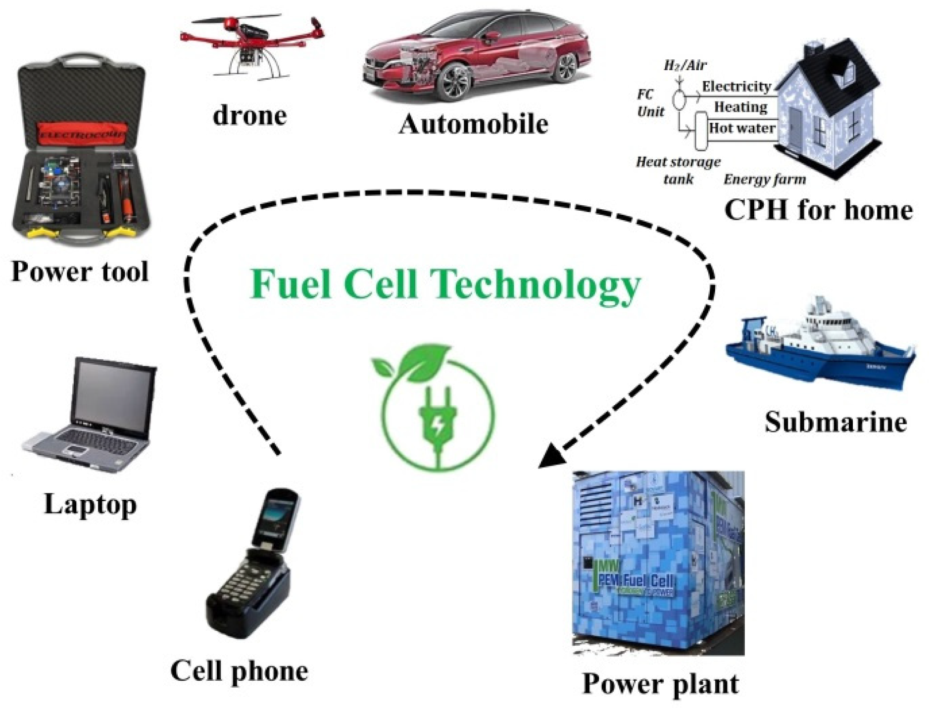
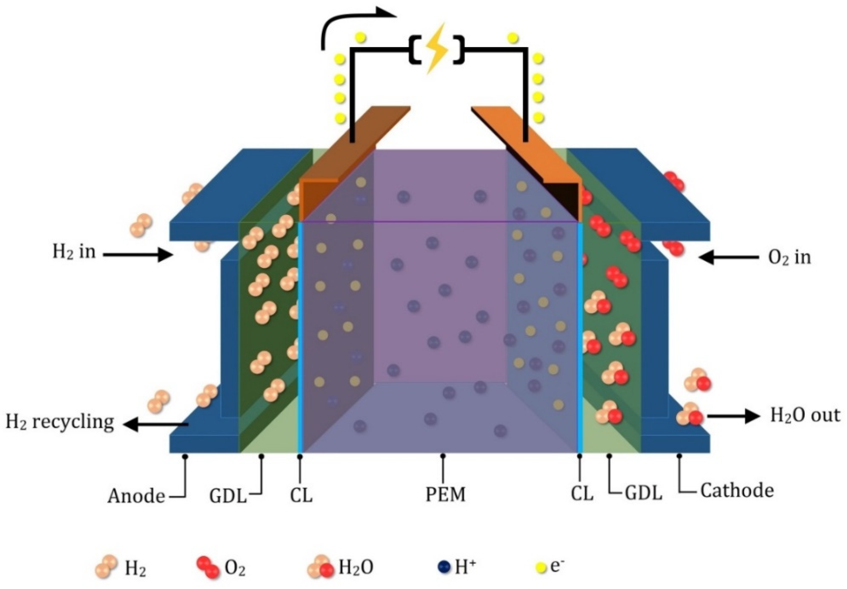
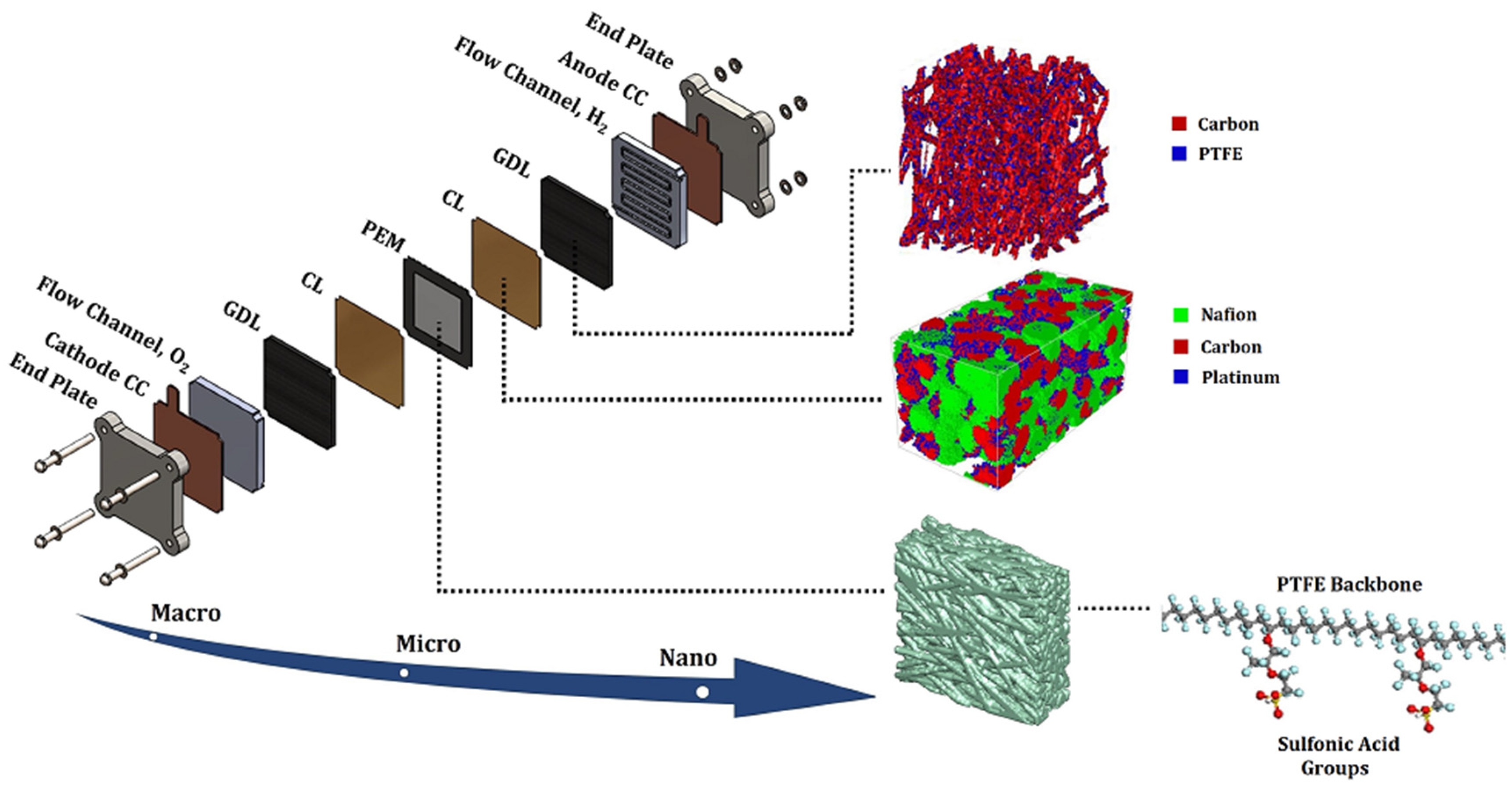
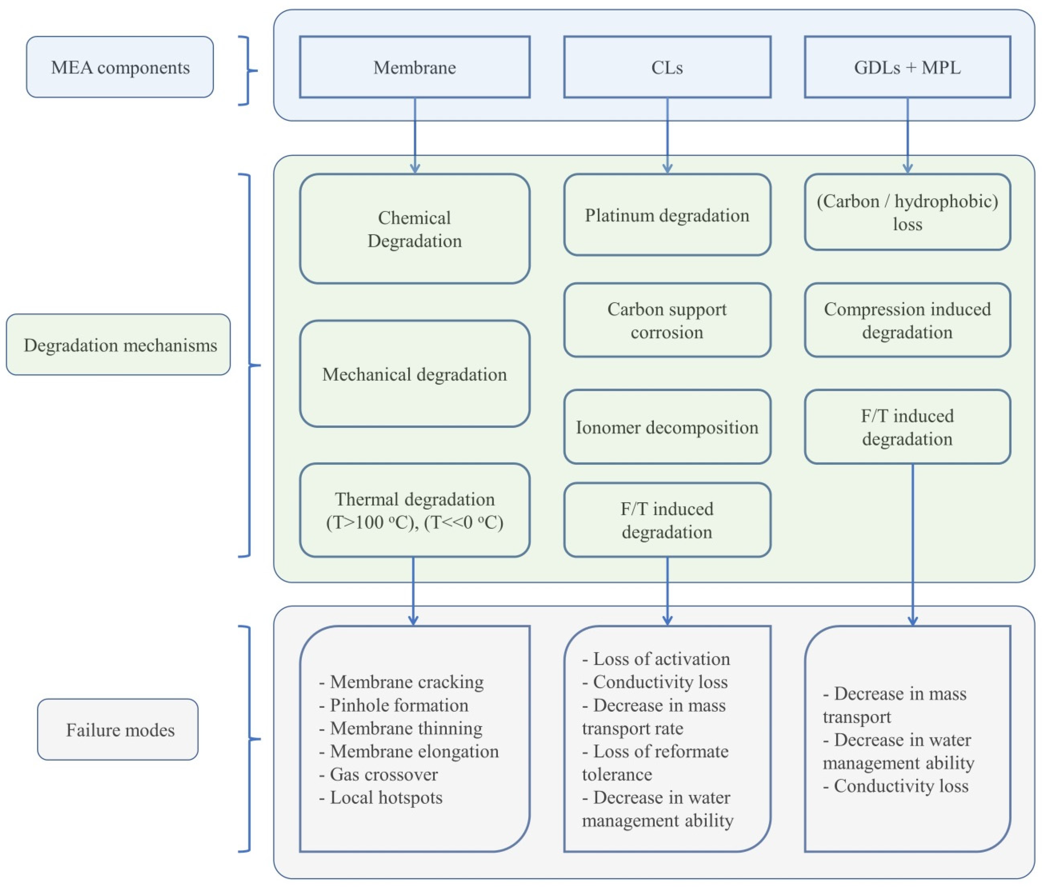
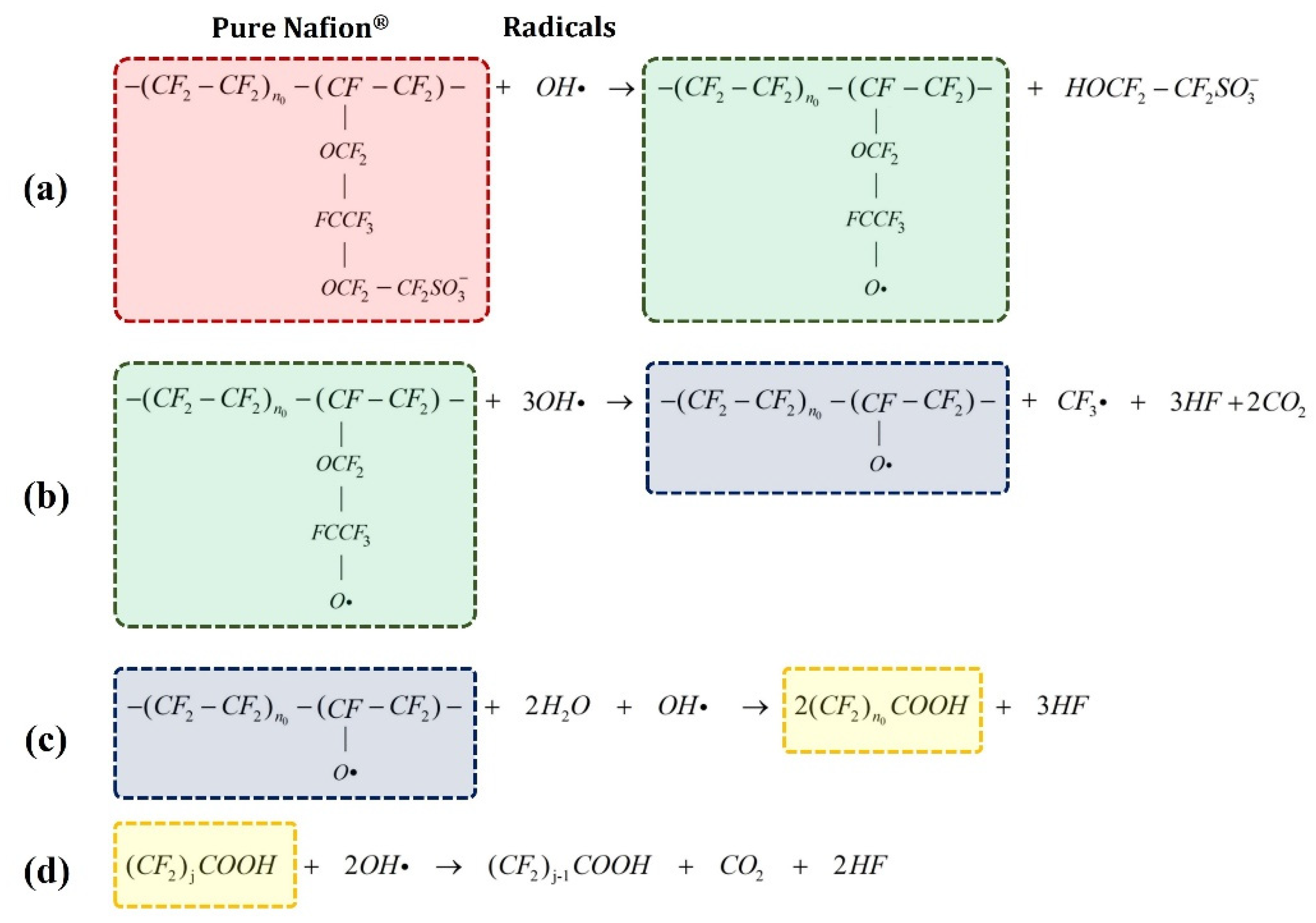
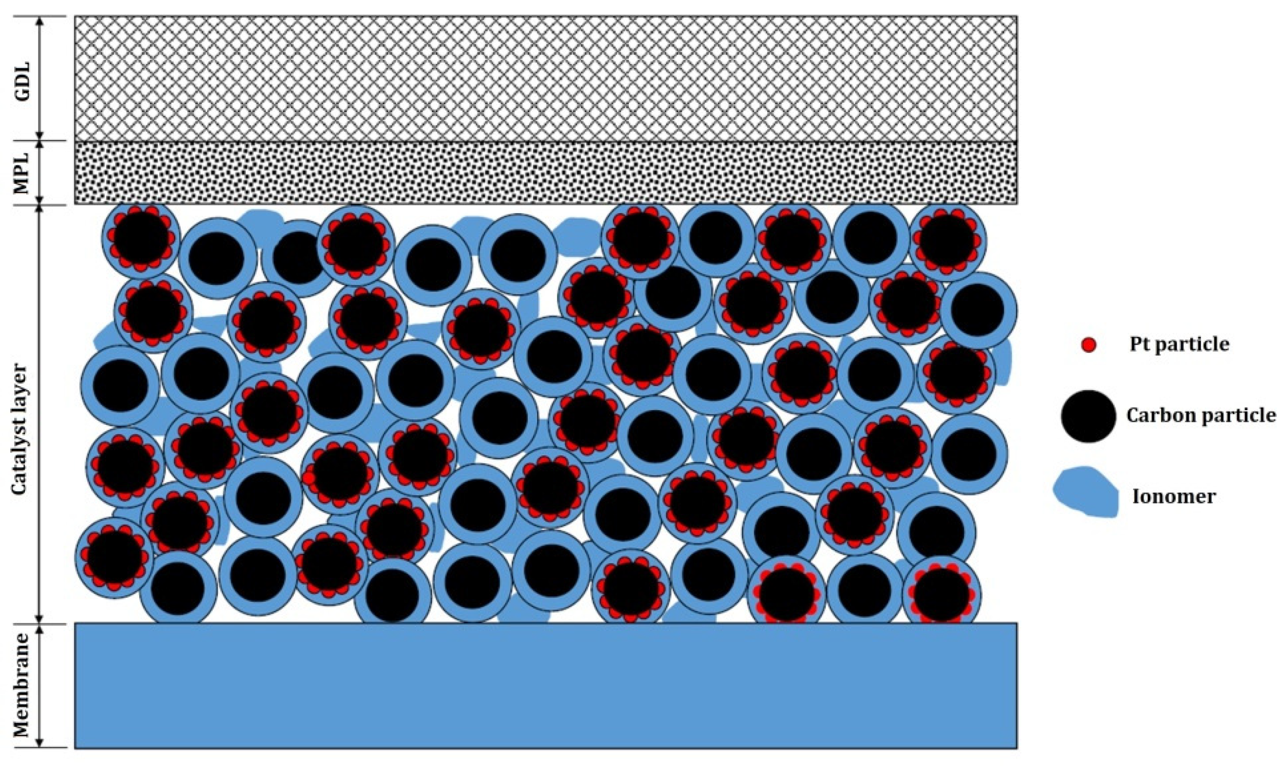
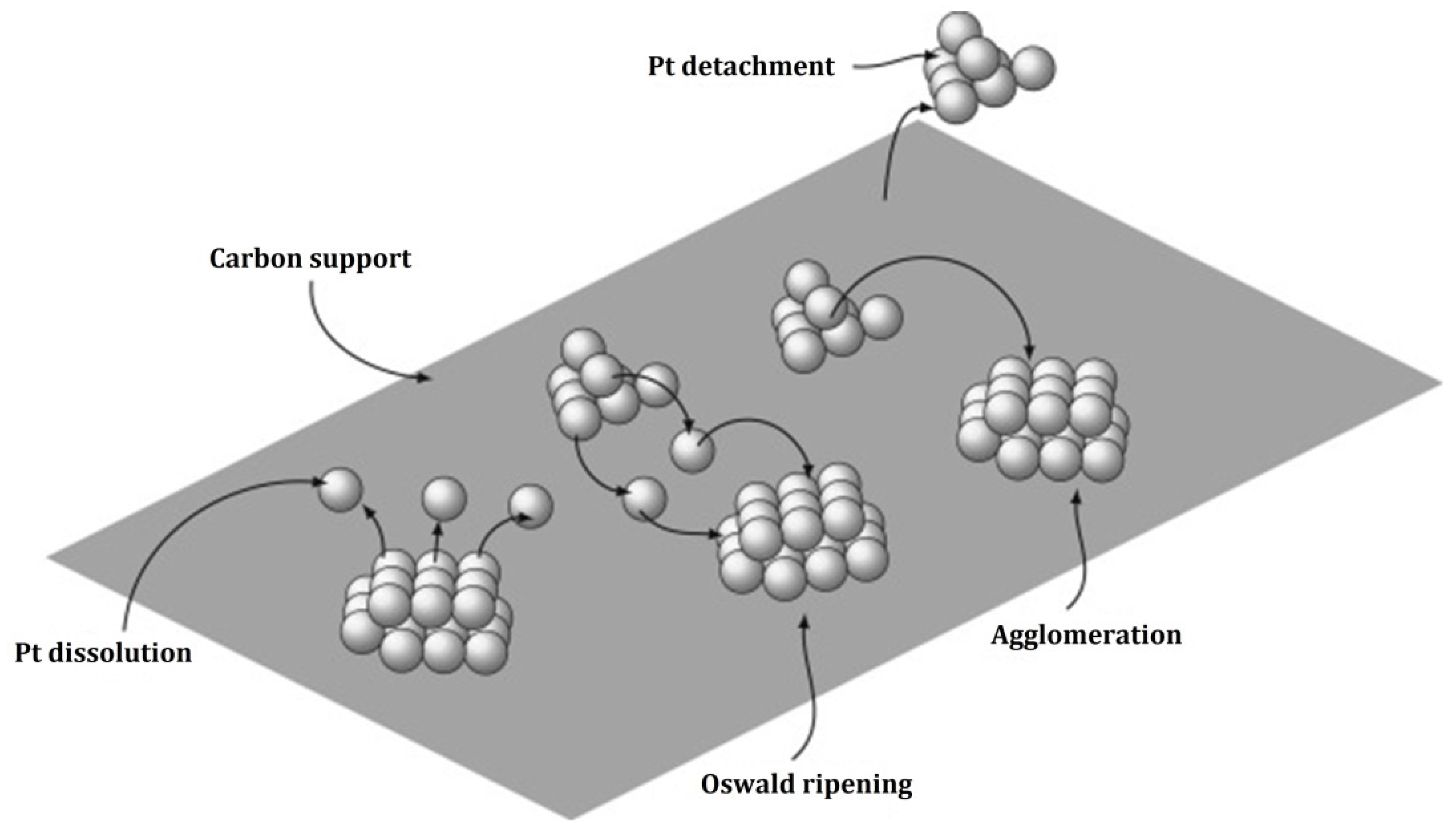
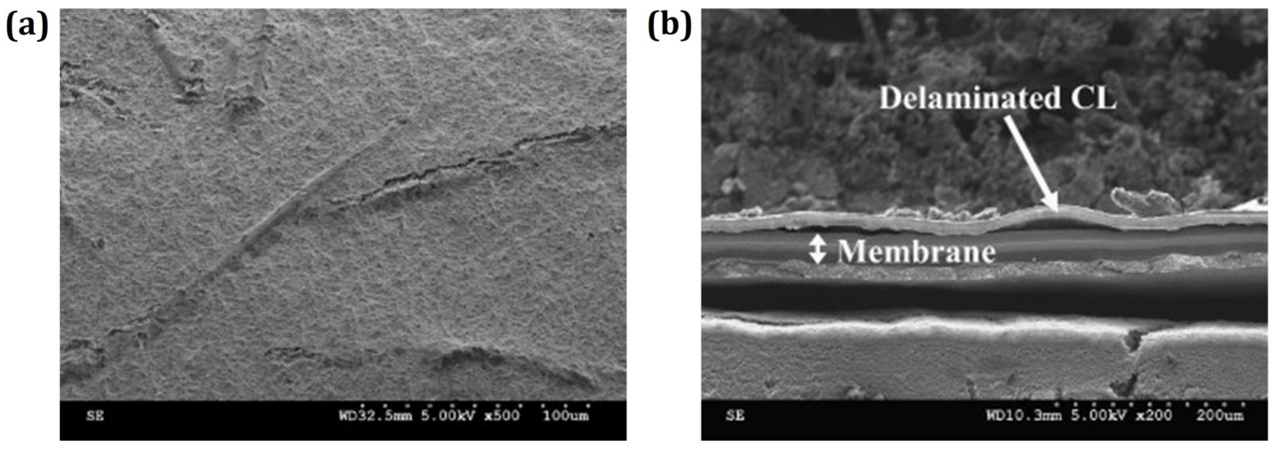
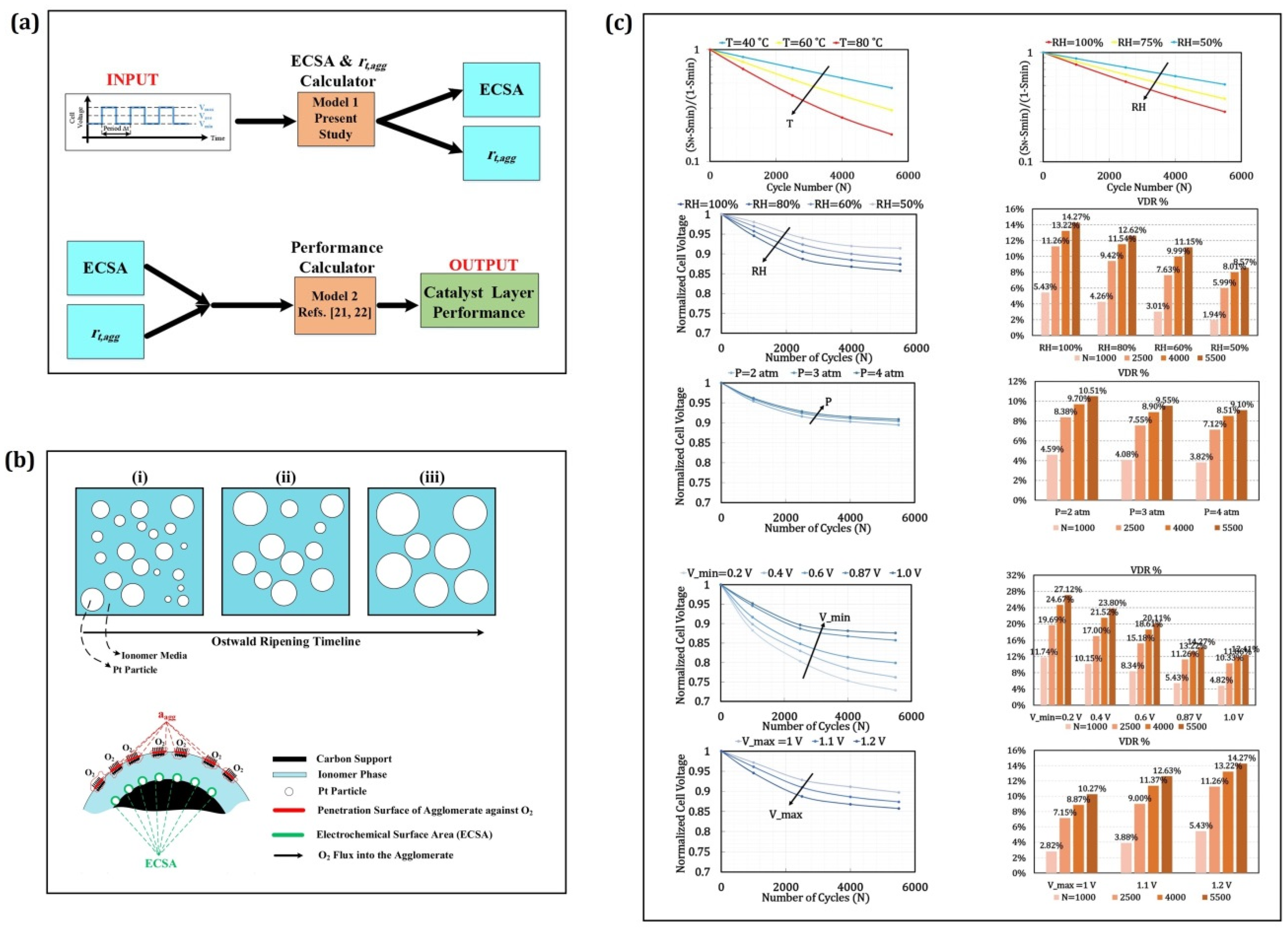
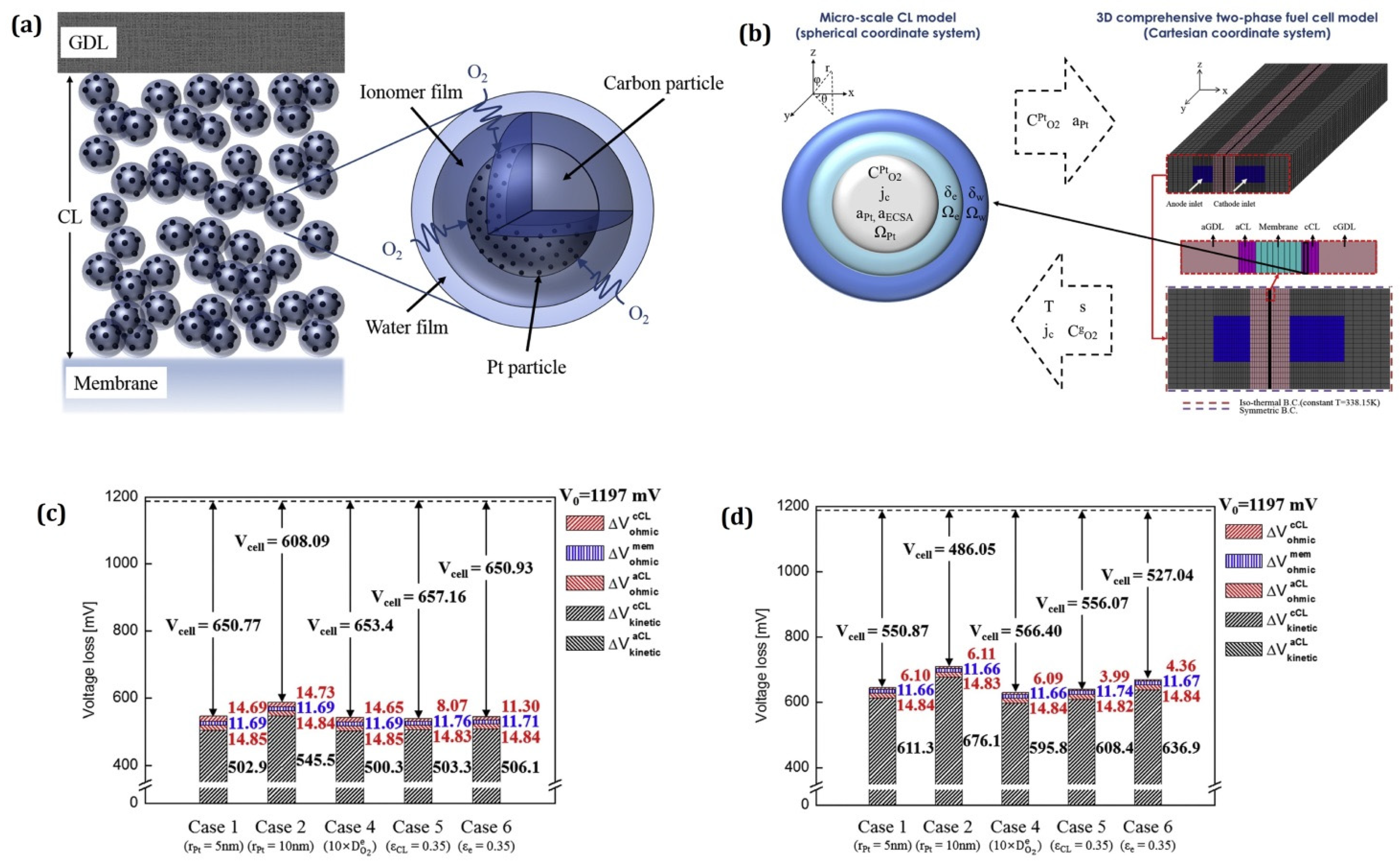
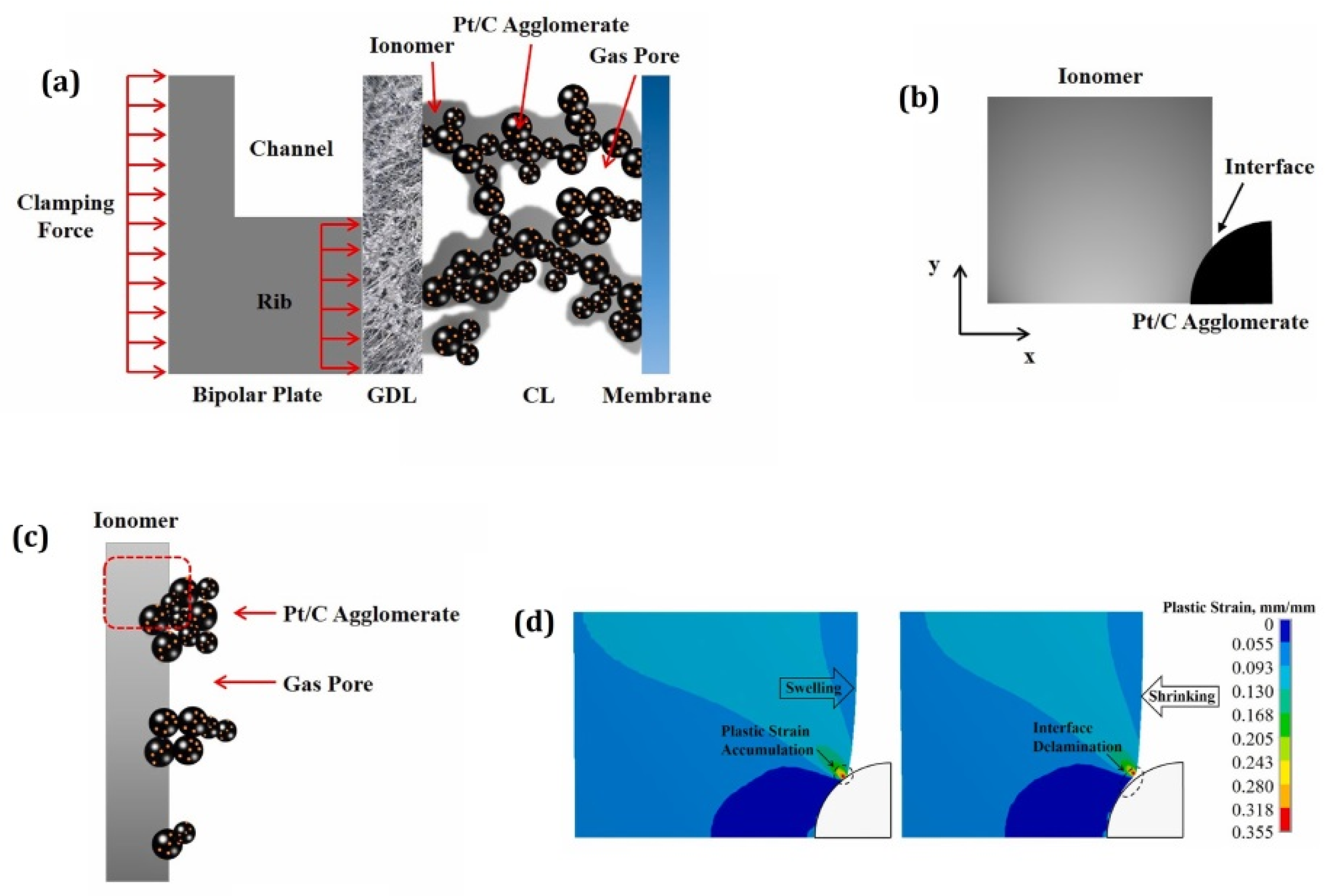
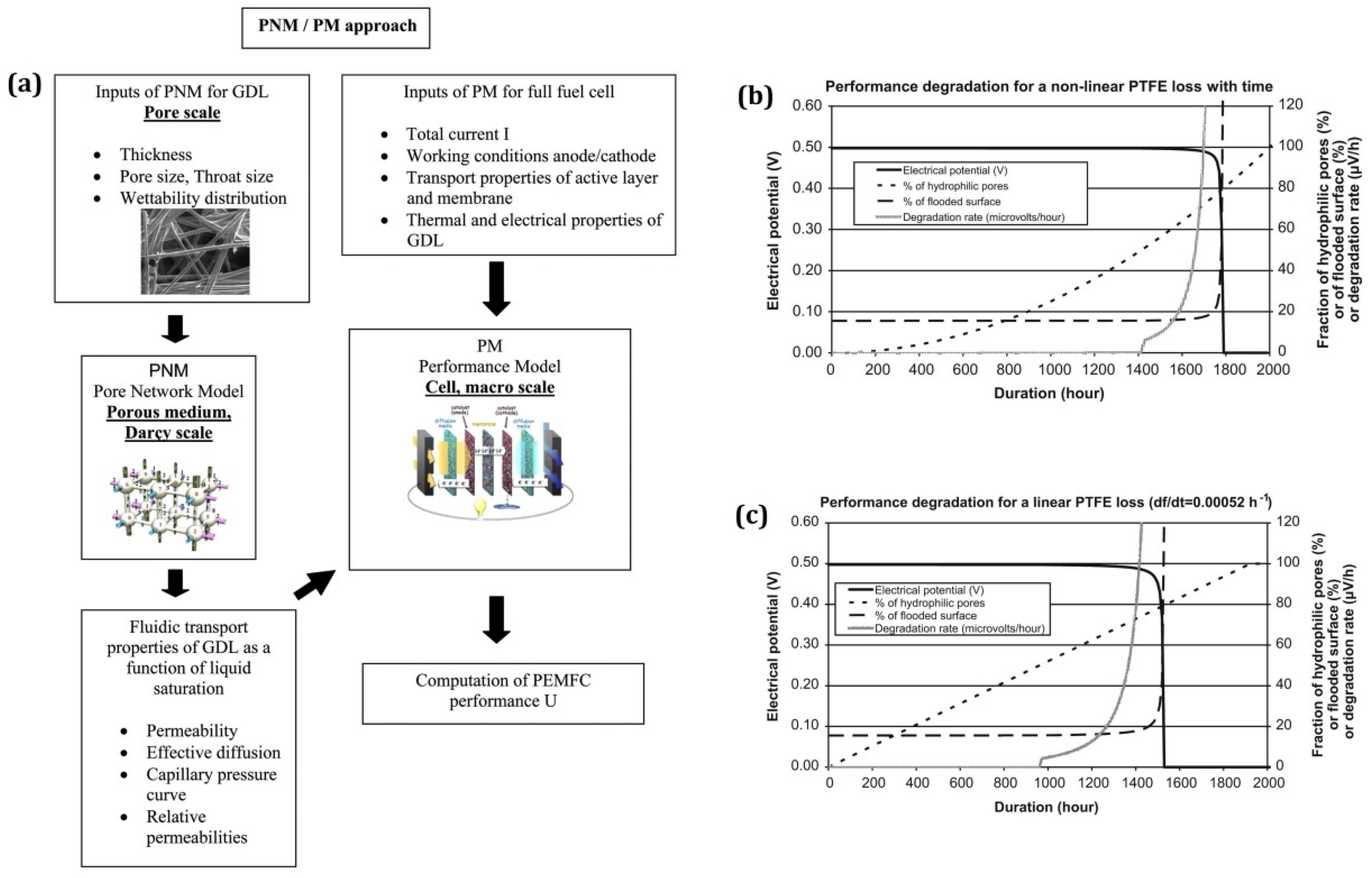
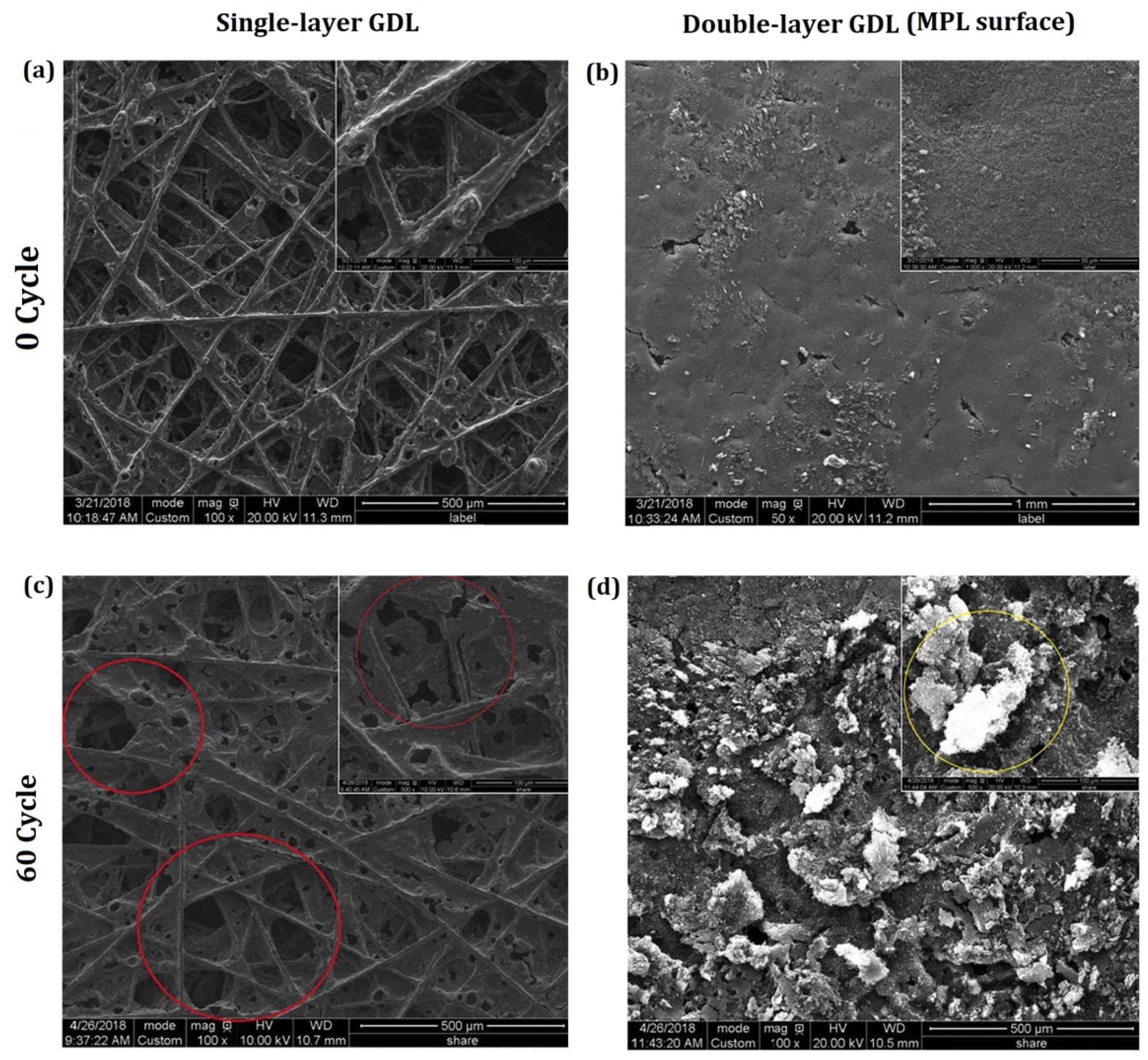
Table 1.
Summary of the membrane degradation models.
| Authors | Year | Model Description |
|---|---|---|
| Tao Xie et al. [56] | 2007 | Chemical degradation: Modeling main chain carboxylic acid unzipping and side chain cleaving |
| Ahmet Kusoglu et al. [65] | 2007 | Mechanical degradation: Modeling the physical response of membrane under humidity cycling |
| A. A. Shah et al. [81] | 2009 | Chemical degradation: Modeling formation of hydroxyl radicals via Fenton reactions |
| Romain Coulon et al. [82] | 2010 | Chemical degradation: Modeling hydroxyl radical formation via Fenton reaction and a radical mechanism of side chain decomposition. |
| H. E. U. Ahmed et al. [69,71] | 2011 | Mechanical degradation: Modeling natural frequency and mode shapes under exited vibration |
| Roshanak Banan et al. [70,71] | 2013, 2015 | Mechanical degradation: Modeling mechanical vibration |
| Kusoglu and Weber et al. [66] | 2014 | Mechanical degradation: Modeling of pinhole growth under environmental cycling loads |
| Seongyeon Won et al. [83] | 2016 | Thermo-chemical degradation: Modeling the degradation of long-run cell voltage |
| Guoliang Ding et al. [61,84] | 2016, 2017 | Mechanical degradation: Modeling crack growth and fatigue due to clamping pressure under humidity cycling |
| L. Karpenko-Jereb et al. [50] | 2016 | Physio-chemical degradation: Temperature, relative humidity, and cell voltage |
| Ka Hung Wong et al. [57] | 2017 | Chemical degradation: Modeling low-voltage degradation of Ceria-supported membrane |
| R. Singh et al. [52] | 2018 | Chemical degradation: Modeling the sequential degradation of PFSA |
| Georg A. Futter et al. [53] | 2019 | Chemical degradation: Modeling of hydrogen peroxide formation |
| Victoria M Ehlinger et al. [48,49] | 2019, 2020 | Physio-chemical degradation: Modeling of pinhole growth under couples mechanical and chemical effect |
| Wenqing Liu et al. [85] | 2020 | Mechanical degradation: Modeling of stress and strain evolution during assembly and operation |
| Weibo Zheng et al. [58] | 2021 | Chemical degradation: Modeling spatial distribution of hydrogen peroxide |
| Y.X. Wang et al. [51] | 2021 | Mechanical degradation: Modeling of crack growth under humidity cycling |
Table 2.
Summary for the CL degradation models.
| Author/s | Year of Publication | Degradation Mechanism/Model Description |
|---|---|---|
| Franco and M. Tembely [102] | 2007 | Pt degradation: Modeling of aging mechanisms in a PEMFC cathode |
| Rong F. et al. [95,114] | 2008 | Structural changes in CL: Modeling of CL microstructure changes induced by load cycling |
| Bi and T. F. Fuller [103] | 2008 | Pt/C catalyst degradation: Modeling of Pt/C catalyst degradation processes using physics-based model |
| T. Takeshita et al. [104] | 2008 | Pt Catalyst Degradation: Modeling of Pt Catalyst degradation using 1D macro model |
| Poornesh K.K. et al. [111,113] | 2010 | Pt/C catalyst degradation: Effect of gradation in catalyst layer on interfacial strength between membrane and catalyst layer |
| Burlatsky S.F. et al. [127] | 2011 | Ionomer decomposition: Modeling of platinum diffusion, precipitation, and band formation in the membrane |
| Colombo E. et al. [128] | 2011 | Pt/C degradation: Modeling the key role of platinum oxides using transient and physical 2D model |
| S. G. Rinaldo et al. [105] | 2012 | Pt degradation: Modeling framework for surface area loss and mass balance phenomena in supported Pt nanoparticle catalysts |
| E. F. Holby and D. Morgan [106] | 2012 | Pt degradation: Modeling of Pt nanoparticle dissolution and oxidation in PEMFCs |
| R. K. Ahluwalia et al. [107,108] | 2014, 2013 | Pt degradation: Modeling the effects of coalescence/sintering of Pt particles on particle growth and ECSA loss |
| Y. Li, K. Moriyama et al. [101] | 2015 | Pt degradation: Modeling of Pt degradation, Ostwald ripening on carbon support and Pt dissolution-re-precipitation through the ionomer phase |
| Li Y. and C.Y. Wang [117] | 2017 | Pt degradation: Modeling of transient platinum degradation under current cycling |
| Moein-Jahromi et al. [118,119] | 2017, 2021 | Pt/C catalyst degradation: Modeling of ECSA degradation, Pt particle growth, the agglomerates via Ostwald ripening, and Pt mass loading loss under cyclic load |
| Randrianarizafy et al. [109] | 2020 | Carbon corrosion: Modeling of the carbon support corrosion and mitigation strategies through the use of a pseudo-3D model |
| Gwak G. et al. [120] | 2020 | Pt degradation: Modeling the oxygen transport resistance and Pt particle growth effect in CL |
| Ghasemi M. et al. [121] | 2021 | Pt degradation: Investigating the usage of TiO2 as Pt catalyst support under different degrees of CL aging using multi-scale two-phase model |
| Chang Y. et al. [129] | 2021 | Structural changes in CL: Modeling the structural changes in CL under humidity and thermal cycling |
| Liu et al. [122] | 2021 | Mechanical degradation: Microstructure changes under accelerated relative humidity cycling |
| Weibo Zheng et al. [99] | 2022 | Pt degradation: Modeling of Pt degradation in the membrane electrode assembly considering Pt mass loss and particle growth mechanisms |
Table 3.
Summary for the GDL degradation models.
| Authors | Year of Publication | Model Description |
|---|---|---|
| Pauchet J. et al. [141] | 2012 | Modeling of the effect of hydrophobicity loss of GDL on performance of a PEMFC |
| Seidenberger K. et al. [142] | 2012 | PTFE degradation: Modeling of water distribution and PTFE degradation mechanisms in PEMFCs |
| Bosomoiu M. et al. [172] | 2015 | Modeling the effective transport properties for fresh GDL vs. aged GDL. |
| Zhang Z. et al. [148] | 2020 | Modeling the microstructure morphology of carbon paper-type GDL using FEM model |
| Zhu L. et al. [170] | 2021 | Simulation approach combining a pore-scale model and lattice Boltzmann method for GDL to study the compression effect |
Publisher’s Note: MDPI stays neutral with regard to jurisdictional claims in published maps and institutional affiliations. |
© 2022 by the authors. Licensee MDPI, Basel, Switzerland. This article is an open access article distributed under the terms and conditions of the Creative Commons Attribution (CC BY) license (https://creativecommons.org/licenses/by/4.0/).
Share and Cite
MDPI and ACS Style
Dafalla, A.M.; Wei, L.; Habte, B.T.; Guo, J.; Jiang, F. Membrane Electrode Assembly Degradation Modeling of Proton Exchange Membrane Fuel Cells: A Review. Energies 2022, 15, 9247. https://doi.org/10.3390/en15239247
AMA Style
Dafalla AM, Wei L, Habte BT, Guo J, Jiang F. Membrane Electrode Assembly Degradation Modeling of Proton Exchange Membrane Fuel Cells: A Review. Energies. 2022; 15(23):9247. https://doi.org/10.3390/en15239247
Chicago/Turabian StyleDafalla, Ahmed Mohmed, Lin Wei, Bereket Tsegai Habte, Jian Guo, and Fangming Jiang. 2022. "Membrane Electrode Assembly Degradation Modeling of Proton Exchange Membrane Fuel Cells: A Review" Energies 15, no. 23: 9247. https://doi.org/10.3390/en15239247
Note that from the first issue of 2016, this journal uses article numbers instead of page numbers. See further details here.