
Torque Control for PMSG-Based Wind-Power System Using Stationary abc-Reference Frame
by
 , ,
, ,
Israel Divan Lopes da Costa
*,
Danilo Iglesias Brandao
* ,
,
Seleme Isaac Seleme, Jr.
and 
Lenin Martins Ferreira Morais
Graduate Program in Electrical Engineering, Universidade Federal de Minas Gerais (UFMG), Antônio Carlos 6627, Belo Horizonte 31270-901, MG, Brazil
*
Authors to whom correspondence should be addressed.
Energies 2022, 15(21), 8060; https://doi.org/10.3390/en15218060
Submission received: 26 August 2022
/
Revised: 23 September 2022
/
Accepted: 1 October 2022
/
Published: 29 October 2022
(This article belongs to the Special Issue Control of Distributed Power Electronic Converters in Smart Energy Systems)
Abstract
:The power system of wind farms is generally characterized by a weak grid, in which voltages may be heavily distorted and imbalanced, challenging the control scheme of wind-power converters that must be impervious to such disturbances. The control scheme in the stationary natural abc-frame has shown good performance under non-ideal voltage conditions, and then this paper proposes to analyze the operational performance of a wind-power system based on a permanent magnet synchronous generator subject to non-ideal conditions of the grid voltage, with its control scheme devised in the abc-reference frame. The proposed control scheme considers the torque control decoupling the flux and torque for the generator-side, showing the possibility to implement the machine torque control, without any coordinates transformation using a closed loop dot-product approach, between the field flux and stator currents. For the grid-side converter, the load current compensation is proposed, using the load current decomposition and conservative power theory (CPT), improving the grid power quality. The simulation results estimate the performance of the grid-side control under distorted and asymmetrical voltages, and the generator-side control against torque disturbances due to wind speed variation. Finally, experimental results in a small-scale test bench validate the proposed control scheme in injecting active and reactive power into the grid, and the torque control under wind speed variation.
1. Introduction
The steady growing of the penetration of distributed generators (DGs) over low-voltage distribution networks is the effect of global electric power demand allied to the deliberate effort of politics to expand the power generation from renewables. Wind-power systems are also connected close to the end-users in a distributed generation approach, in which commercial, industrial, agricultural, and community sites are examples of such applications, whose wind turbines range from 1 kW to 600 kW [1]. The heavy generation of active power into the grid gradually raises the voltage level, causes reverse power flowing, and may impair the voltage quality (i.e., distortion and asymmetry), which challenges the grid-tied wind-power converters.
The typical condition of a weak power grid in wind farms and low-voltage microgrids accentuates the undesired current circulation in the network, which in turn may cause torque oscillation in the generator shaft, a reduction in efficiency, overheating in the generator’s windings, and the shortening of the expected lifetime of the generator itself and the converter´s electrolytic capacitor due to DC voltage oscillation created by imbalance. So, it is expected from the grid-tied inverters’ proper dynamic stiffness regarding the rejection of disturbances coming from both the load current and the grid voltage, and multifunctionalities, in order to mitigate the unwanted current terms (i.e., reactive, harmonic and imbalance) drawn by the non-linear loads.
The variable-speed wind energy conversion system (WECS) based on the permanent magnet synchronous generator (PMSG) has drawn the attention of industry for small-scale wind power generation in a low-voltage network because it shows higher power density besides greater reliability due to the absence of precision gears and brushes compared to other technologies [2]. The common configuration of a PMSG-based wind turbine feeding a grid-tied inverter is composed of a synchronous generator and a back-to-back power converter that exchanges power between the generator and the grid sides. The back-to-back converter comprises a generator-side converter that regulates the delivery of wind-turbine power and a grid-side converter that regulates the DC-link voltage coupling both converter sides [3].
The typical implementation of torque control in synchronous machines regulates the magnitude and phase of the stator current using a flux-oriented control [4]. It can be achieved through several different control methods, including (1) the regulation of the direct (isd) and quadrature (isq) stator current sensing the absolute rotor position [4]; (2) speed sensorless control schemes [5]; (3) direct torque and direct power control (DTC) [6]; and (4) phase-voltage oriented control, without using a rotor position sensor or sensorless estimator [7]. The first method consists in converting current commands in the rotor reference frame to a stator reference through a transform equation based on the generator parameters and the instantaneous rotor position. The second method proposes to estimate the rotor position/speed using a fundamental-frequency model that can be based on open-loop calculation or closed-loop observer. Sensorless methods are very promising because they reduce financial cost and enhance reliability; however, many critical issues, such as stability, robustness, and complexity, may be carefully considered [5]. The direct torque/power control presents advantages such as robustness, simplicity, and a quick dynamic response, and it has been widely used as for the wind turbine converter ACS800 from ABB [8]. The main disadvantages of direct torque control (DTC) is its large torque/flux ripples and unstable switching frequency. Nevertheless, several DTC techniques have been proposed in order to contour these issues [6], such as space-vector-modulated DTC, model predictive DTC [9], and duty-cycle-modulated DTC [10]. The phase-voltage oriented control uses a phase-locked loop (PLL) to establish the current control of the PMSG, following a unity power factor correction. The similarity between all the aforementioned control strategies is to rely on the dq-reference model or dq-reference-control scheme.
The authors of [11] have compared the performance of three-phase four-wire active power filters using the id–iq method (synchronous reference frame), instantaneous pq-strategy (αβ reference frame), and two strategies that can be implemented in a natural abc-reference frame: the unity power factor (UPF) strategy and the perfect harmonic cancelation (PHC) strategy. This paper concludes that the id–iq method and pq-strategy are the most sensitive strategies under distorted and asymmetrical voltage conditions. In fact, the control strategies devised in the abc-frame have the advantage of dealing directly with the positive- and negative-sequence components in the fundamental frequency, whereas those that appear in the αβ- and dq-frame act as a signal with twice the fundamental frequency [12]. Thus, based on this conclusion regarding the operational performance of inverters under the non-ideal voltage condition, and considering the PMSG-based WECS for modern low-voltage power systems, this paper devises the PMSG control scheme in the abc-frame.
The proposed control scheme considers the torque control decoupling the flux and torque for the generator-side converter, and the load current compensation for the grid-side converter, enhancing the grid power quality. It is worth mentioning that the authors of [12,13] have applied the abc-frame control only to the grid-side converter, while the generator-side control was implemented in a synchronous reference frame. To the best of the authors’ knowledge, the generator-side control scheme in the abc-frame has never been presented in the current literature, and it is the main contribution of this paper. Moreover, it is an extended version of [14], emphasizing the control scheme, the modeling, and presenting further simulation and experimental results, validating the proposed torque control for the generator-side converter of PMSG for WECSs.
In the following, Section 2 describes the PMSG-based WECS, and Section 3 presents the control schemes going through the abc-frame modulation methods, generator-side modeling, torque control, and design of the controllers. Section 4 shows the simulation results, while Section 5 shows the experimental ones. Finally, Section 6 concludes.
2. Wind-Power System
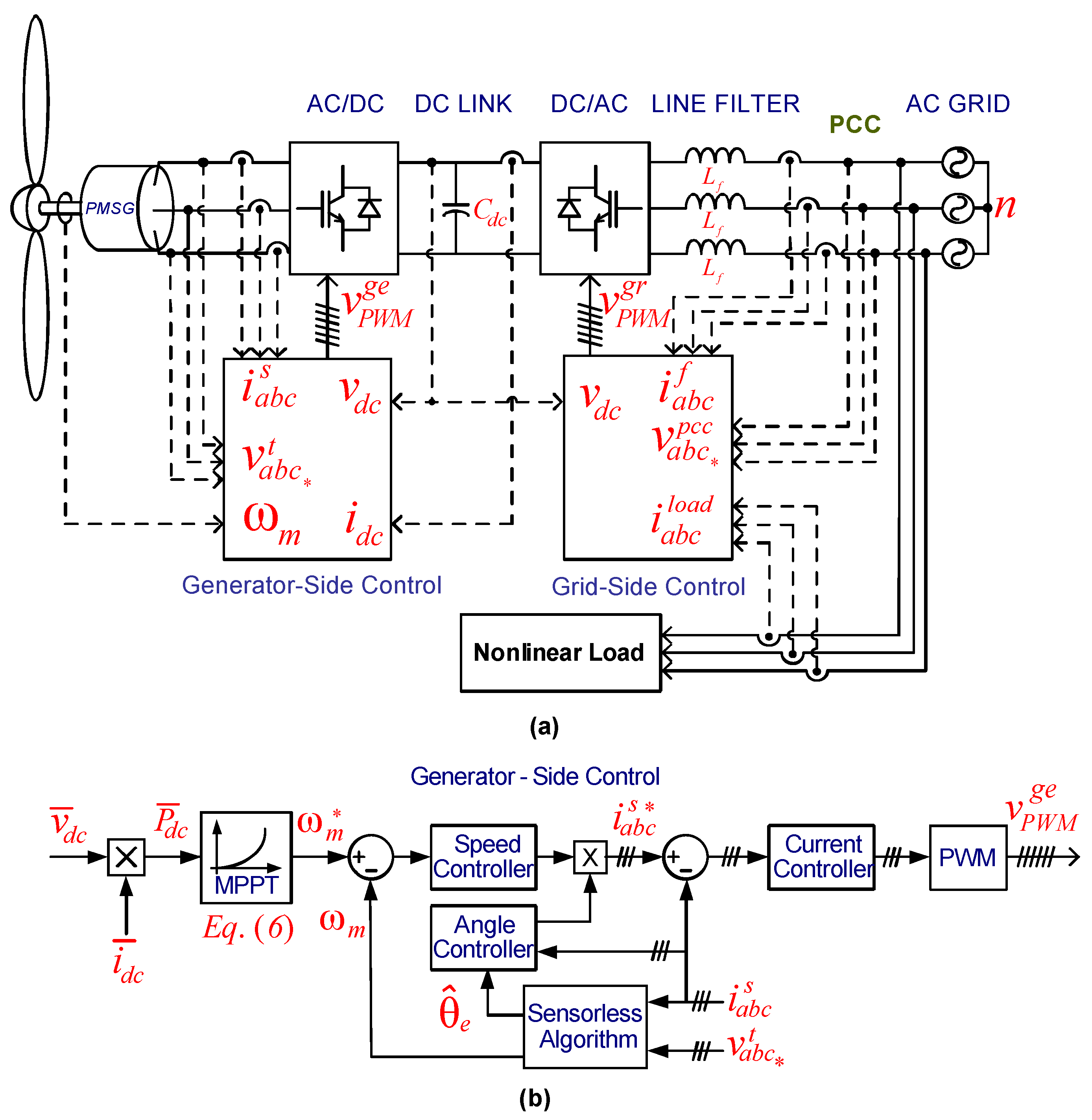
The considered wind-power system is depicted in Figure 1, composed of a back-to-back, two-level converter connecting a wind-turbine, PMSG, to the mains through an inductive filter, and non-linear loads at the PCC. The control scheme of the back-to-back converter is fully implemented in the abc-frame, and it is split into a generator- and grid-side control. The generator-side control is shown in Figure 1b, and it comprises the maximum power-point tracking (MPPT) algorithm; the estimation algorithm of the shaft speed; and the control loops of stator current, electric angle, and mechanical speed control. The grid-side control is shown in Figure 1c, and it comprises the decomposition algorithm responsible for breaking the load current down into current terms for the purpose of selective compensation, and the control loops of the output current and the DC-link voltage.
The generator-side control of Figure 1b regulates the speed control tracking the MPPT and ensures the proper torque control decoupling the flux and torque in order to improve the dynamic response. The grid-side control of Figure 1c aims at guaranteeing the active power feed-in with a high power factor and a low value of current THD. It must meet the minimum grid-code requirements for grid-tied inverters [15]. Besides the active power injection, it has highly desirable ancillary services such as voltage support, dynamic reactive power injection, and selective current compensation [16]. Finally, the DC-link voltage of the back-to-back converter is regulated by the grid-side converter. Section 3 goes through the control loops.
2.1. Wind-Turbine Model
The mechanical power Pwind [W] available in the wind is represented by (1) [17]. Where ρ [kg·m−3] is the air density, Rt [m] is the blade length, and [m·s−1] is the wind speed.
The power conveyed from the wind turbine to its shaft is weighted by the power coefficient , which is dependent on the construction of the turbine and dictates the efficiency of the power transfer.
where the factors to are constant values, herein c = [0.5176, 116, 0.4, 5, 21, and 0.0068], [°] is the blade pitch angle, and is the blade tip-speed ratio due to the wind speed in a time instant [18].
With the variable of
[rad·s−1] is the mechanical speed at the electrical machine axis. Finally, the generator shaft dynamic is represented as
where [kg·m2] is the total moment of inertia of the rotating mass (i.e., turbine plus generator), B [N·s/m] is the viscous friction coefficient, [N·m] is the mechanical torque at the generator shaft, and [N·m] is the electromagnetic torque.
2.2. The Maximum Power-Point Tracking
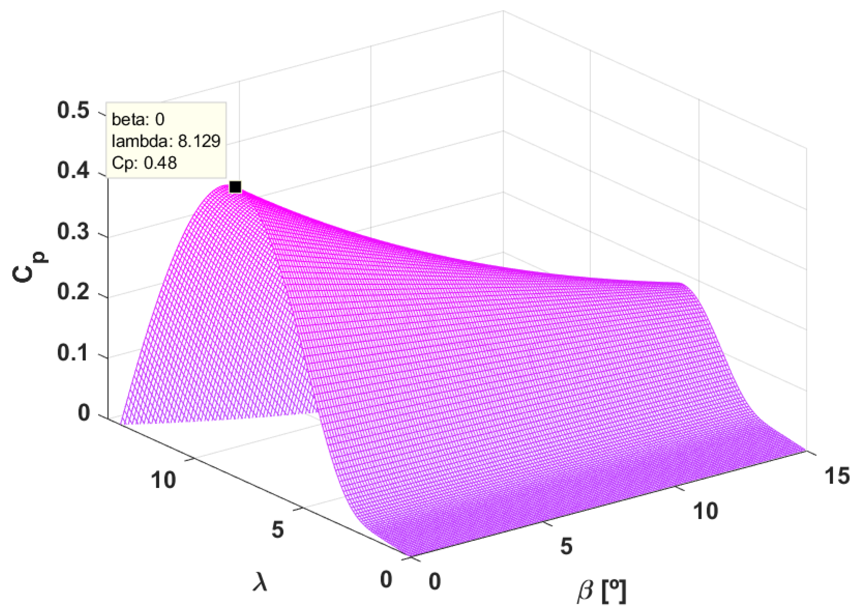
The maximum mechanical power transfer from the wind to the turbine shaft occurs when has its maximum value. Figure 2 shows the curve of Cp represented by (2). The maximum power transferring occurs when = 0° and = 8.129 (i.e., ), with = 0.48 (i.e., ). Note that there is a local maximum point (, ) for each value of the pitch angle. Replacing in (2) and then in (1), for a fixed value, provides an expression for the MPPT:
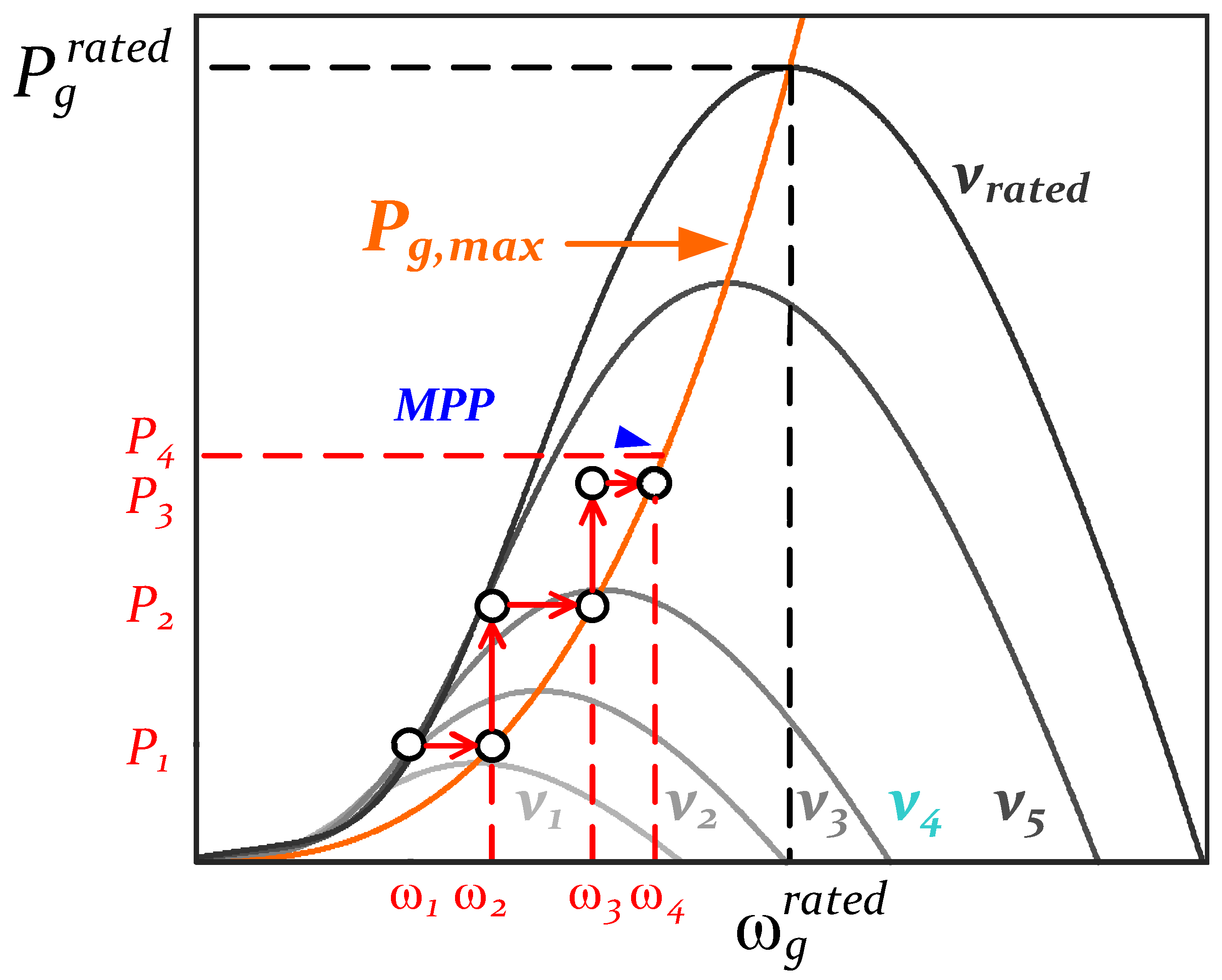
Note that the generator power is a function of its rotor speed, which provides a set of curves as shown in Figure 3. As proposed in [19], Equation (6) can be used for the MPPT by means of sensing the generated power at the DC link of the back-to-back converter. Figure 3 also shows how the tracking of the maximum power point is accomplished for a specific wind speed. If initially the sensing power is P1, the speed reference for the generator is driven to ω2, which in turn increases the mechanical speed, and the generated power goes to P2. Then, this process occurs cyclically until it reaches the vicinity of P4, i.e., the maximum power point.
3. Control of PMSG Power System in abc-Frame
The PMSG control scheme is split into the grid- and generator-side. The former control scheme is widely discussed in the current literature, even in the abc-frame and considering the multifunctional capability of grid-connected inverters [20,21]. On the other hand, to the best of the authors’ knowledge, the generator-side control scheme in the abc-frame has never been presented in the current literature, and it is the main contribution of this paper. So, this section is focused on the latter control scheme, and it goes briefly through the grid-side one.
3.1. abc-Frame Modulation Method
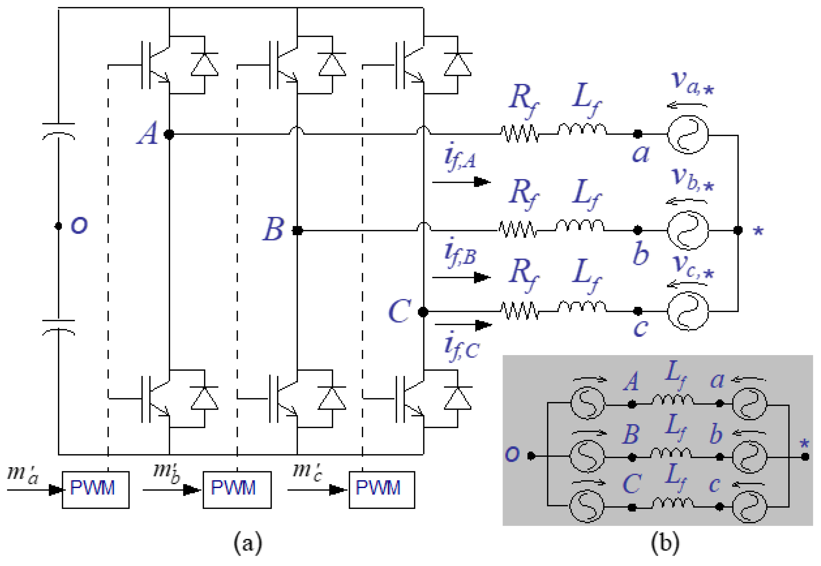
The three-phase, three-wire converter shown in Figure 4a presents a coupling between its output current, if, X, and the input voltage at the converter terminals, vX. Its equivalent model shown in Figure 4b, considering the converter topology as three voltage sources, and disregarding the intrinsic resistance of inductors, can represent the circuit of Figure 4a. Then, it is modeled by (7), which shows a coupling between if, X and vX [10]. Usually, the current control of this converter is performed using the reference frame transformation to the stationary αβ-frame or to the synchronous dq-frame, in order to avoid the input/output variable coupling.
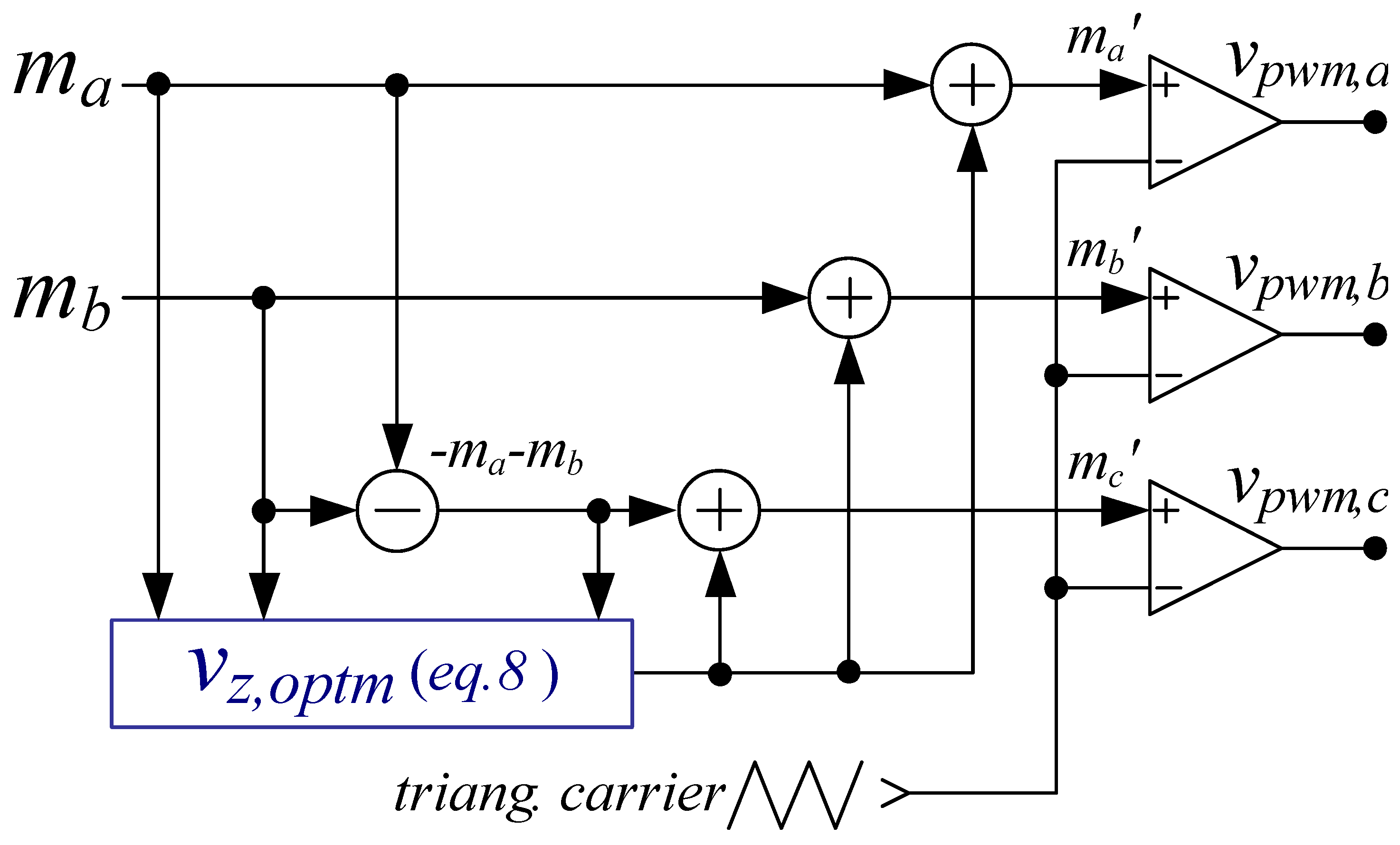
The decoupling of the input/output variable for the system’s proper operation in the stationary abc-frame implementation can be achieved by using the number of phases of the system minus-one controllers, e.g., the three-phase, three-wire converter would need two controllers. This can be devised using two different methods: (1) setting the extra output reference to zero and (2) setting the extra output reference to be the negative sum of the other two references [22]. The first method inconveniently increases the modulating signal amplitude, even using the optimal zero-sequence value method, as calculated by (8). The second method overcomes this drawback, and it can be used, in conjunction with (8), independently of zero-sequence component. Herein, the second method has been used, as shown in Figure 5, for both control schemes (grid- and generator-side converters).
Then, the strategy of using the number of phases of the system minus-one controllers, associated with the optimal zero-sequence method, (1) can fully explore the voltage modulation capability, (2) does not require reference frame transformation, (3) can be easily implemented in commercial microprocessors, and finally (4) shows superior performance in following a reference signal when it has a negative-sequence component if compared with αβ- and dq-strategies [12,23]. However, this paper does not intend to compare the different control strategies but to propose the torque control in the abc-frame for the generator-side converter of a PMSG wind-power system.
3.2. Generator-Side Converter
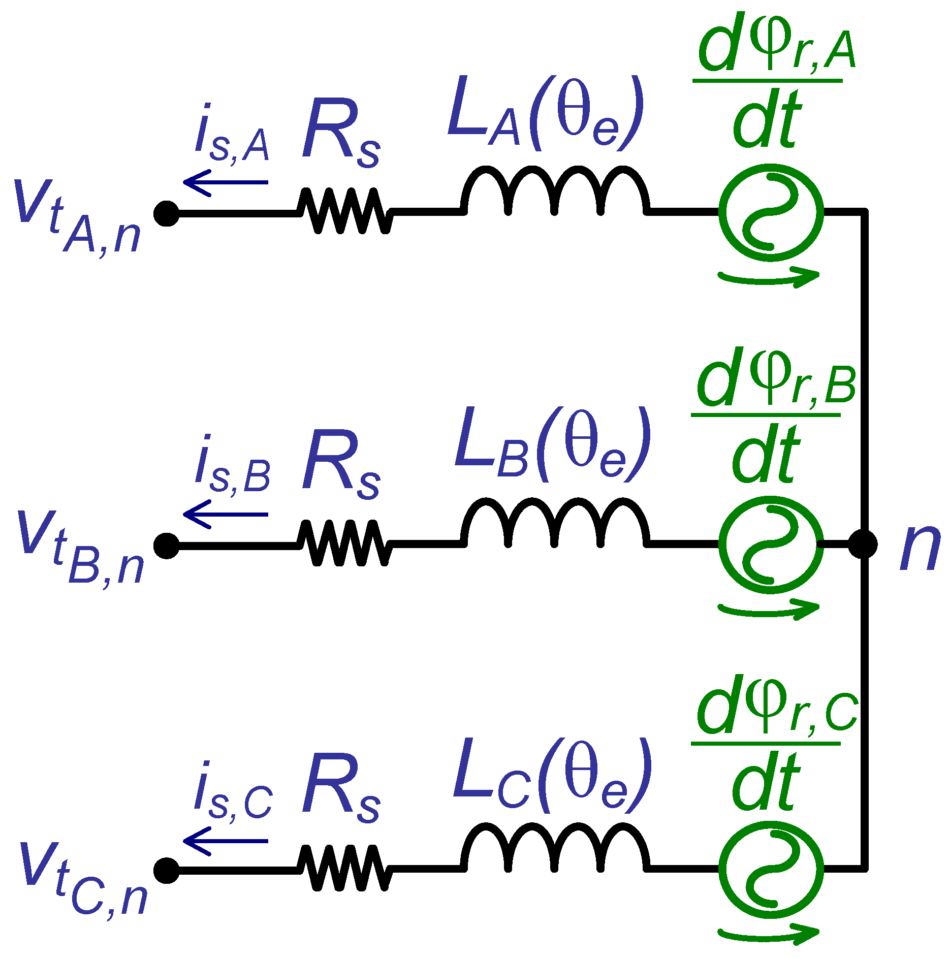
Figure 6 shows the equivalent circuit of a PMSG in a wye connection. The stator currents, , and the rotor flux linkages, φr, X, are considered to be sinusoidal and symmetrical. The considered PMSG in this paper has salient poles; then, the self, LX, and mutual, MX inductances vary sinusoidally with the rotor position, which is twice the electric angle, θe (i.e., two pairs of poles) [22].
where Lls is the leakage inductance and Lm is the magnetizing inductance. Then, the mutual inductance expressions are
The terminal phase voltage equations are obtained by Kirchhoff’s voltage law:
As the stator windings are wound with the same number of turns, so the stator resistances are all equal, Rs, and the stator flux linkage () equations are
is the rotor flux linkage. The generator model is assumed linear, which is a fairly approximation without saturation.
3.3. Torque Control
The torque-control method regulates the electromagnetic torque through instantaneous current control, and then it adjusts the shaft speed with rapid dynamics, improving the system dynamic stiffness against torque disturbance [4]. To achieve torque control, the following requirements must be met at every instant of time: (i) the constant value of the field flux; (ii) independent control of the armature current; and (iii) orthogonal spatial angle orientation between the armature magnetomotive force and the field flux (so that both variables are decoupled).
3.3.1. abc-Frame Considerations for PMSG Control
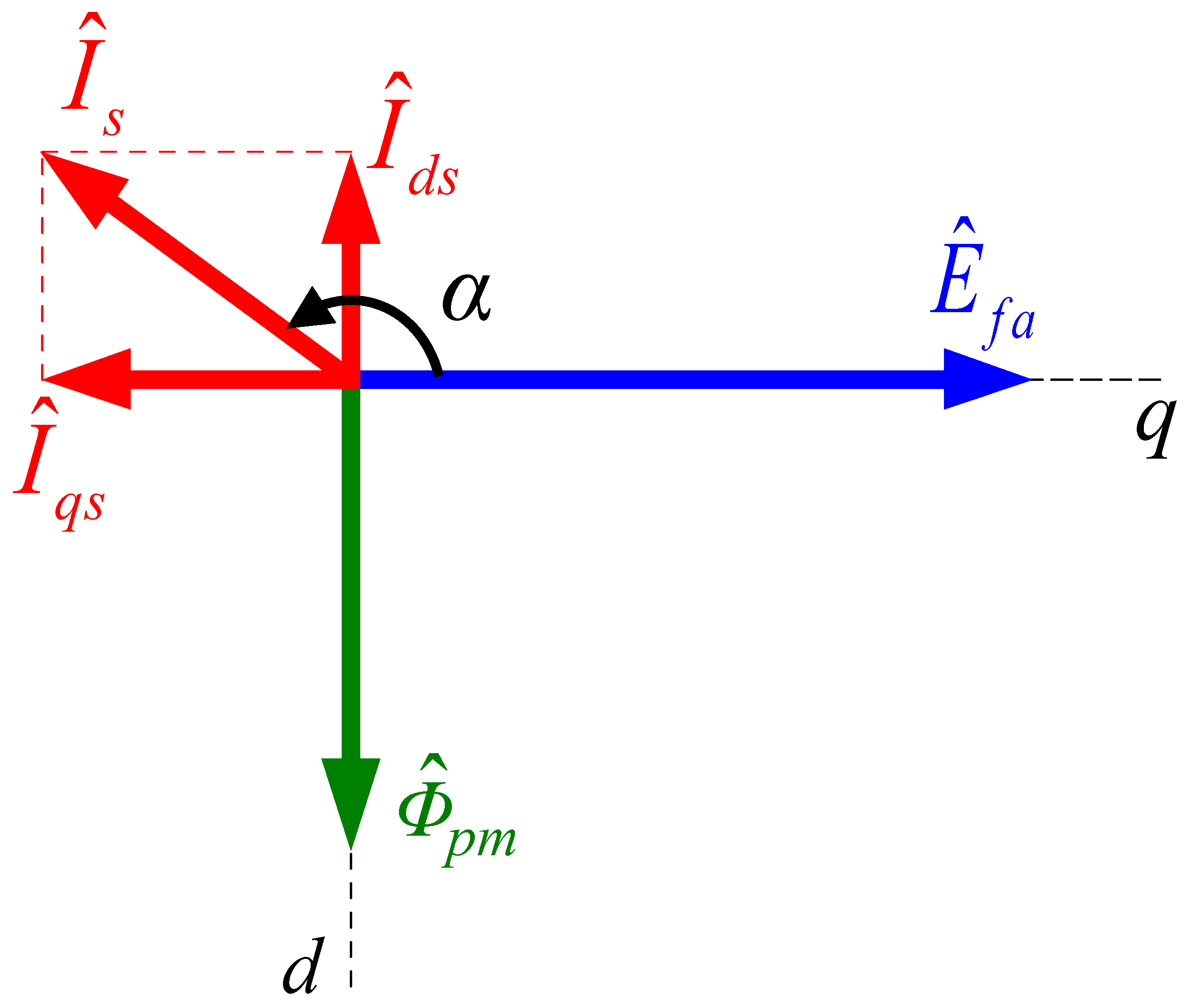
For a PMSG, according to the generator convention [24], Figure 7 shows the synchronous dq-frame vector diagram with the induced armature voltage (blue), ; the permanent magnet field flux (green), ; and the stator current (red), , decoupled into its direct, , and quadrature, , terms.
The electromagnetic torque can be calculated as a function of the angle between the induced voltage and the stator current, [4]:
where pp is the number of pairs of poles, and Ld and Lq are the direct and quadrature inductances, respectively. The electromagnetic torque is composed of the reaction torque and the reluctance torque. The reluctance-torque component vanishes if α is regulated to 0° (i.e., motor convention) or 180° (i.e., generator convention), and the torque magnitude is controlled through the stator current magnitude. It corresponds to split the stator current into direct (id) and quadrature (iq) components, making the d-component zero, while the q-component is the reference value required to provide the appropriate electromagnetic torque. So, in a steady state, the stator current has only the q-component, i.e., the stator current is Is In terms of speed regulation in the natural abc-frame, the same field orientation is achieved by synchronizing the stator current with the induced armature voltage. It can be implanted by measuring the shaft mechanical angular frequency via an encoder or by tracking the electric angular frequency using a sensorless estimation method, as developed in [18,25]. Herein, the latter method was chosen, i.e., the estimation of the machine electrical angle .
3.3.2. Torque and Power Equations in the abc-Frame
By definition, torque is change in energy per angle variation, and assuming that the magnetic system is linear, the coenergy is [24]:
Such bold variables represent three-phase vectors. The torque produced by the machine is
which results in (16):
The previous equation can be expanded in three separated terms: , , and , as follows:
The terms and result from the self and mutual inductances, respectively. The sum of both terms represents the reluctance torque. The last torque term, named reaction torque, is due to the back-EMF and the stator phase currents, and it corresponds to the major contribution of Te. By trigonometric relations, it is possible to prove that [26] if the stator currents are symmetrical and in-phase with the back-EMF (also symmetrical), the terms of T1 and T2 become zero, and then the reaction torque, T3, corresponds to the electromagnetic torque:
where is the peak value of the stator currents and is the peak value of the permanent magnet flux linkage. Then, multiplying the torque by the mechanical angular frequency results in power.
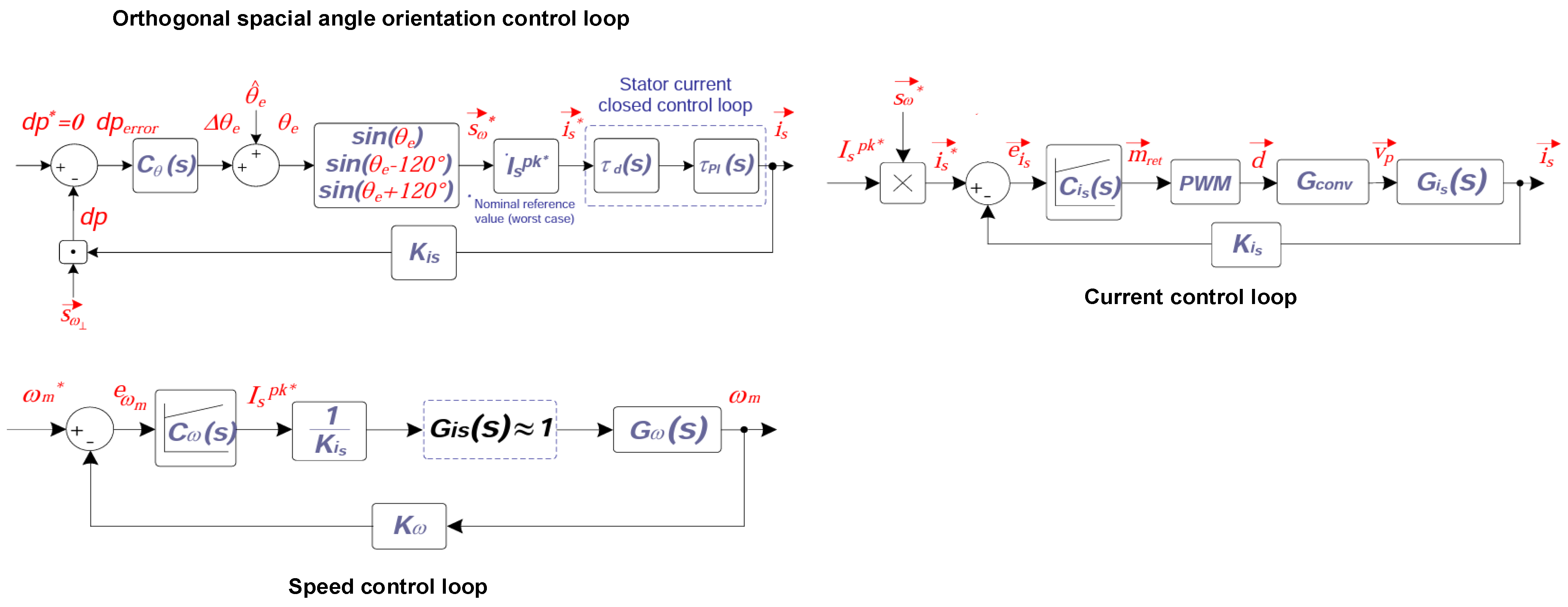
3.4. Generator-Side Control Loop
The complete model to design the generator-side controllers is shown in Figure 8. An outer loop regulates the mechanical speed through a proportional-integral (PI) controller. The mechanical speed reference, , is provided by an MPPT algorithm (6) as discussed in Section 2. Then, the PI controller, , generates the stator peak current reference (). Subsequently, it is multiplied by a symmetrical three-phase set of signals with unit amplitude, . Such a signal could be generated through the estimated machine electrical angle , but it is not very accurate, causing steady-state error and not guaranteeing orthogonal spatial angle orientation during transient. Therefore, a closed-loop control, , must be added in order to provide to such desired features. The control-loop principle is that the induced armature electromotive force in each phase is orthogonal to the permanent-magnet field-flux variation that induces itself. Thus, if each phase of the stator currents is exactly in-phase with its corresponding phase of the armature electromotive force, the dot product of must result in zero. Let us define the variable dp as this scalar product, , because it is used later to evaluate the proposed control torque capacity for decoupling the flux and torque in both steady-state and transient.
Finally, the multiplication of results in a vector that is the phase-stator current reference to the inner current control loop, . This control loop is based on two PI controllers, which, combined with (8), provide the three-phase modulation signal, , to the PWM.
3.4.1. Inner Stator Current Controller
The open-loop transfer function used to calculate the stator current controller, :
where Cpk is the PWM carrier peak value, Vdc is the DC-link voltage nominal value, and Kis is the gain of the stator current sensor.
3.4.2. Mechanical Speed Controller
The open-loop transfer function is used to calculate the PI controller, :
such that the parameter is the mechanical speed sensor gain. The other variables were previous defined.
3.4.3. Orthogonal Spatial Angle Orientation Control Loop
The open-loop transfer function is used to calculate the PI controller, :
such that is the cut-off angular frequency defined with regard to the stator current closed-loop and is the nominal peak value of the stator current.
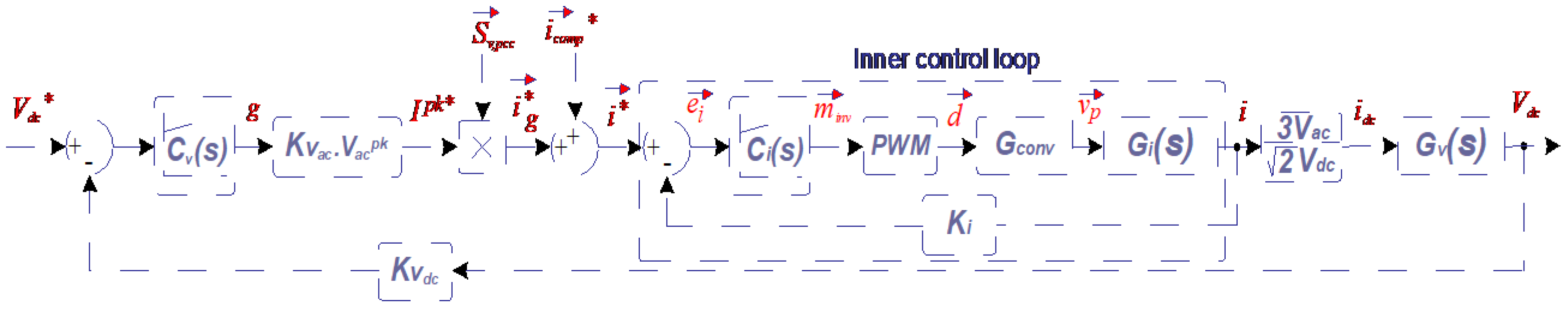
3.5. Grid-Side Control Loop
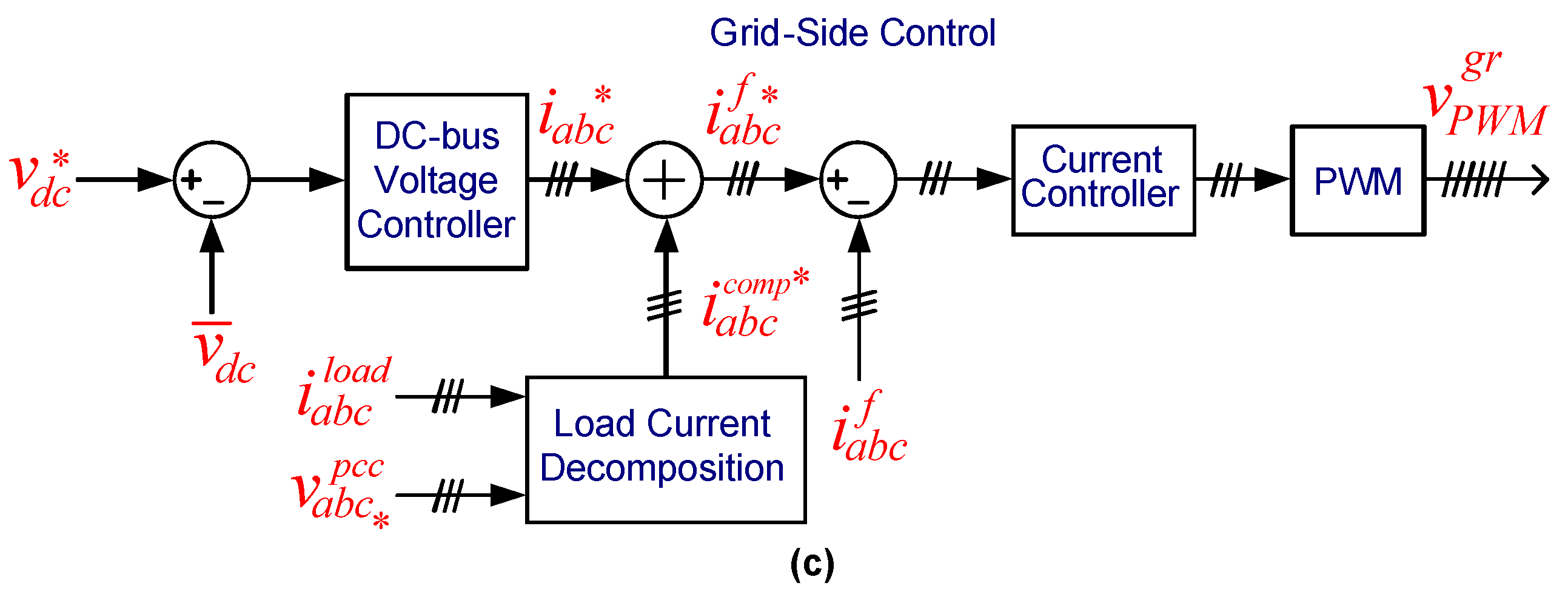
The complete model to design the grid-side controllers is shown in Figure 9. An external DC voltage-control loop regulates the DC-link voltage using a PI controller, Cv. Then, the output of this PI controller is a conductance signal that multiplies a synthetized signal generated through a PLL algorithm [27] tracking the grid voltage. is used to provide a sinusoidal shape to the current reference that corresponds to the active current terms required to ensure the power balance between the DC and AC sides. A second part of the current reference, , is added to , resulting in the grid current reference, . To have a current controller capable of tracking an AC signal into the main harmonic orders, proportional multi-resonant controllers are designed, as described hereafter, and combined with (8), they provide the modulation signal to the PWM. Finally, the compensating current corresponds to the undesired current terms that the grid-side converter must compensate, such as an active power filter. These current terms are generated herein using the current decomposition of CPT [28], which may provide selective compensation of electrical disturbances (i.e., reactive, imbalance, and harmonics) [16].
3.5.1. Inner Inductor Current Controller
The open-loop transfer function used to calculate the multi-resonant current controller, :
where Ki is the gain of the current sensor.
3.5.2. Outer DC-Link Voltage Controller
The open-loop transfer function used to calculate the PI voltage controller, :
where Kvca and Kvdc are the AC and DC voltage-sensor gains, and , , and are the nominal value of rms voltage, peak voltage, and DC-link voltage, respectively.
The parameters are shown in Table 1. The controllers were designed in the basis of frequency methods: the desired crossover angular frequency of the magnitude of the open loop transfer function is equal to one, and its phase is equal to the desired phase margin (PM) [29,30]. Then, the chosen phase margin and chosen crossover frequency are shown in Table 2. All those controllers are PI, except (𝑠), which is a proportional multi-resonant controller (27).
where kp is the proportional gain; ki,h are the integral gains for each selected frequency, i.e., 1, 5, 7, 11, 13, and 19° frequency components; and ωh and ωb are the bandwidth of the resonant controller.
It is worth mentioning that the simulation system was developed on the basis of an experimental set-up in which the synchronous generator possesses few poles (i.e., four poles). A typical PMSG for WECS application generally has many poles in order to run with low mechanical speed. So, the experiment and simulation are considered a gear relation between the turbine and the generator axes of 1/4.25.
4. Simulation Results
The behavior of the proposed control scheme for the PMSG system is evaluated through Matlab/Simulink simulation. The considered circuit is shown in Figure 1, with the sized controllers as discussed in Section 3. This section evaluates the torque control and the compensation capability under distorted and asymmetrical grid-voltage conditions.
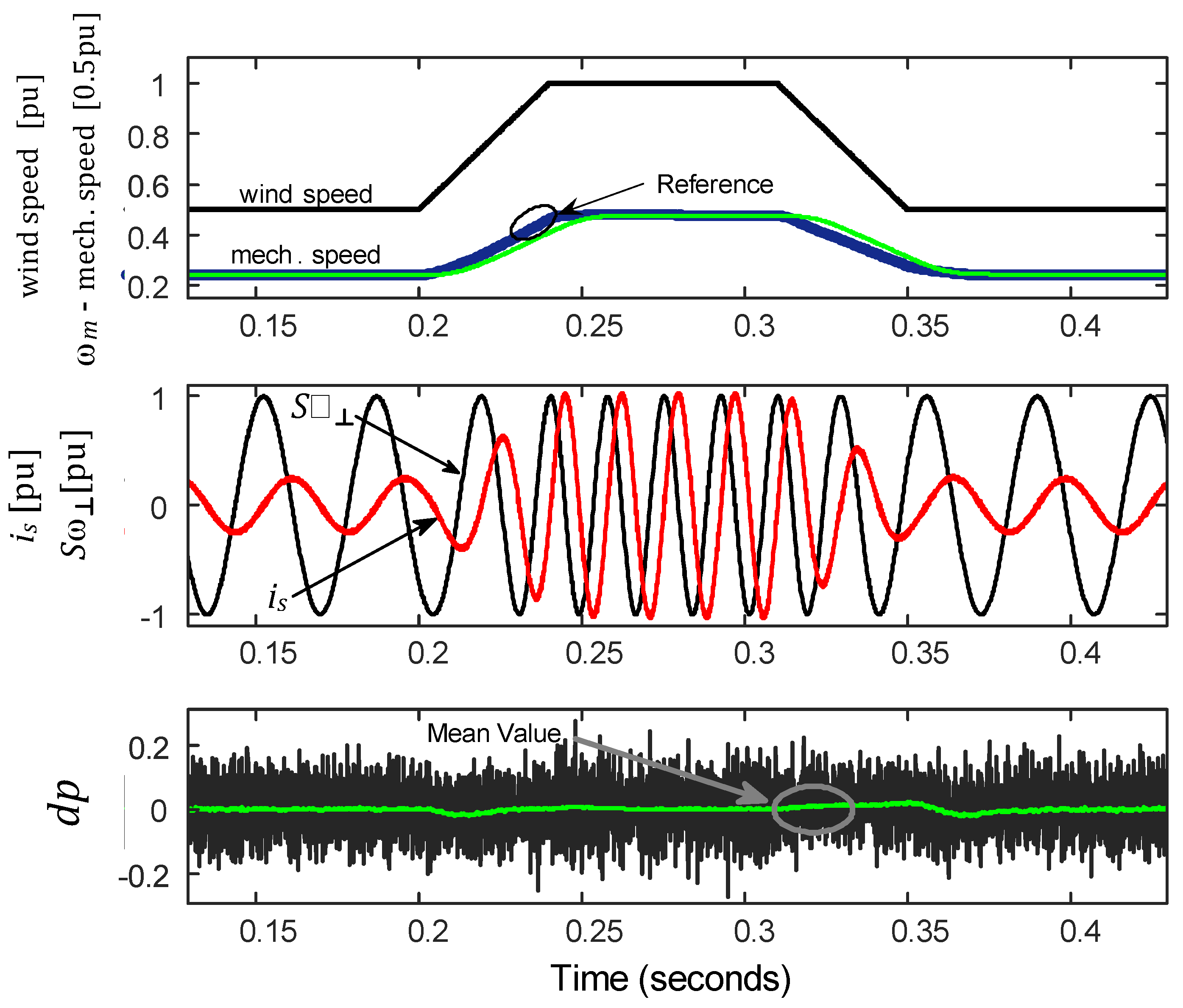
4.1. Wind Speed Variation
Figure 10 shows the mechanical speed at the generator shaft while the wind speed varies, in order to test the MPPT algorithm and the mechanical speed control loop. The wind speed varies from 0.5 pu to 1 pu in a ramp up of 40 ms, and then it returns to its initial value in a ramp-down starting at 0.31 s. Note that the mechanical speed curve scale in Figure 10 is reduced by a factor of 0.5. From the top graphic, one can see the dynamics of the system, and from the bottom graphic one can see its dynamic stiffness against speed variation. This result evaluates whether the proposed control strategy for PMSG is effectual in cancelling the reluctance torque (13) during speed variation, which guarantees the control of torque magnitude directly through the stator current magnitude (21). It can be seen by the orthogonal characteristic of and , and the zeroing average value of the dp variable (green curve in the bottom graphic), as explained in Section 3.4, if the average value of dp is zero; this means that flux and torque in the generator-side are orthogonal to each other.
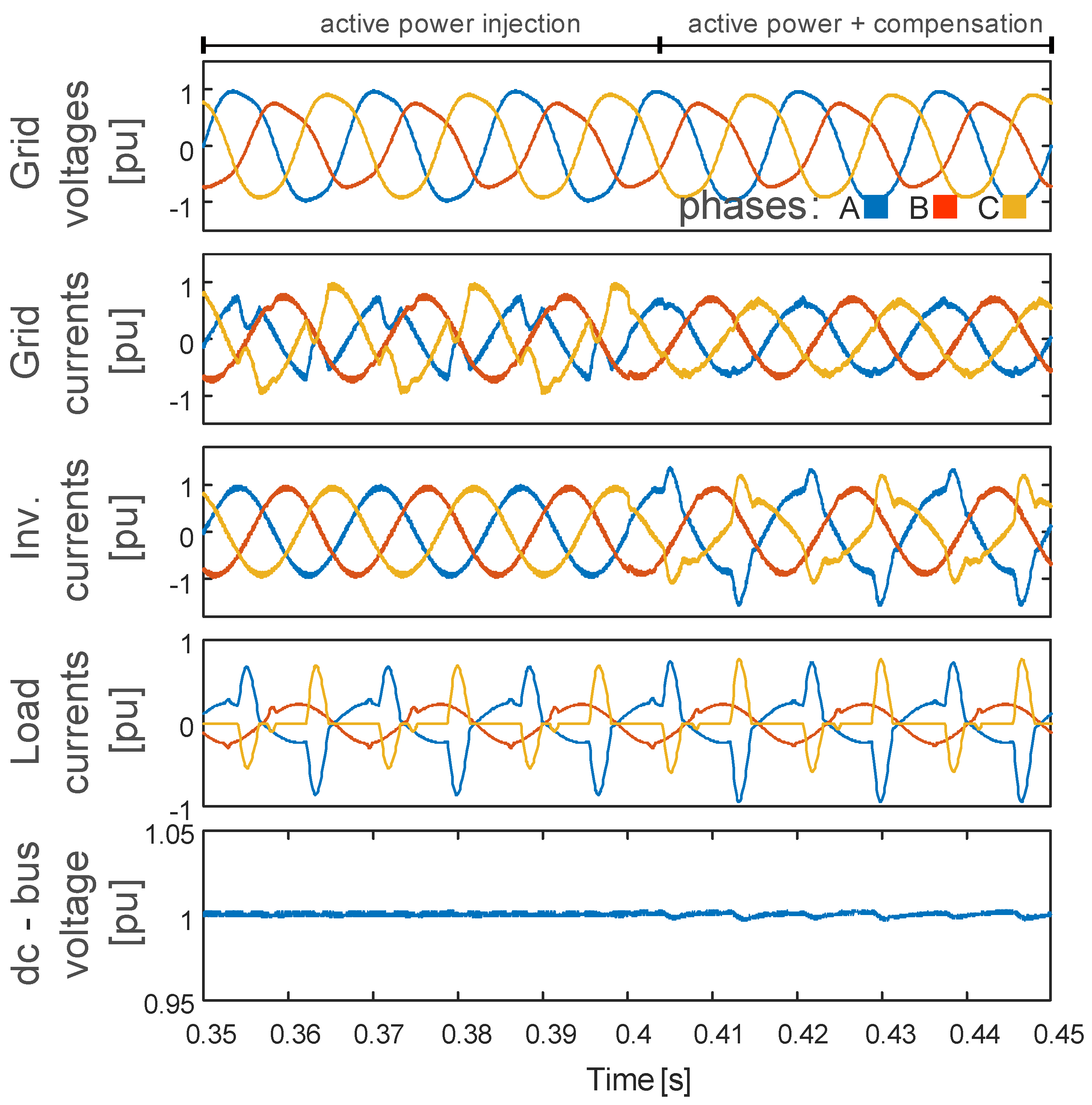
4.2. Asymmetrical and Distorted Grid Voltage
This result considers the wind system in its nominal set point, and Figure 11 is split into two instants. Firstly, the PMSG injects only active power into the grid, and secondly, it generates active power and simultaneously compensates for reactive power, harmonic current, and the imbalance of the local load (i.e., the non-active current term), as shown in Figure 1. The phase-voltage magnitudes and their THD values are 171 V (9.1%), 135 V (11.1%), and 153 V (0.9%) for phases a, b, and c, and the THD values of the load currents are 103.7, 11.5, and 57.8 % for phases a, b, and c, respectively. Before 0.4 s, the grid currents are highly distorted with THD of 46% (phase a) and 31.5% (phase c), while phase b shows 5.6%. The power factor value at the PCC is about 0.80. After 0.4 s, the converter compensates for the non-active term of the load current, and then it enhances the grid current quality, reducing the THD values to 7 (phases a and c) and 5% for phase b. Note that the grid current imbalance is also improved, as well as the power factor value that achieves 0.99. The bottom graphic of Figure 11 shows the DC-link voltage, and during the compensation, it shows negligible oscillation. Such DC voltage oscillation is expected because of the instantaneous active power oscillation at the converter terminals, which is a matter of the engineering sizing of the DC capacitor value. However, if properly sized, the multifunctional capabilities of the grid-side converter may have a minimal impact on the generator-side one.
5. Experimental Results
The experimental results validate the devised control scheme in the abc-frame and the designed controllers. This section tests the torque control and the active and reactive power injection into the grid.
5.1. Experimental Prototype
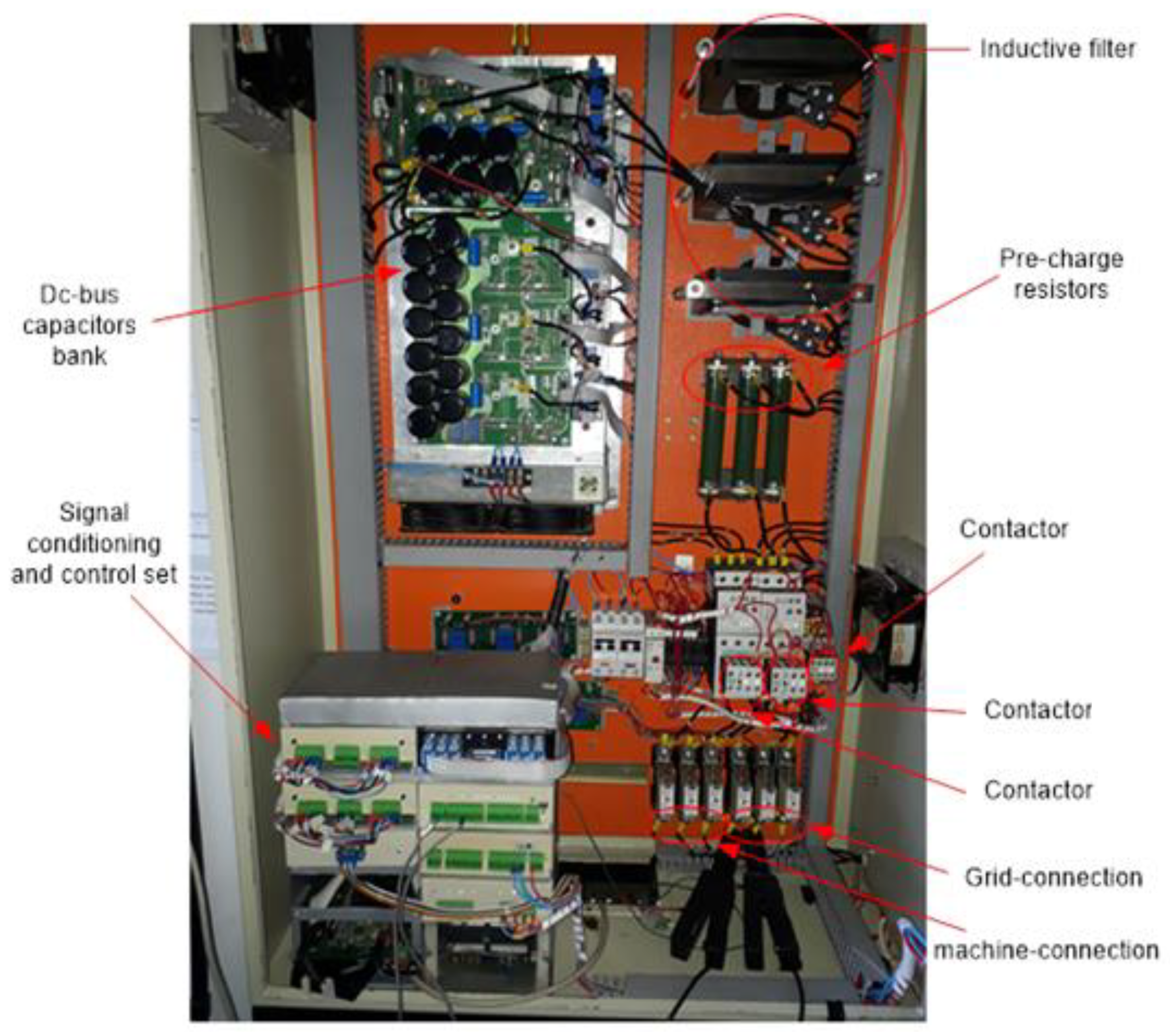
The laboratory-scale prototype, shown in Figure 12, has the same parameters as the simulation circuit. Its main components are a three-phase, three-leg voltage source rectifier and inverter, assembling a total of six SK30GB128 Semikron IGBT modules. The digital control scheme was devised in a floating-point digital signal processor (TMS320F28335). Both the generator- and grid-side converters are driven by PWM technique with a sampling frequency of 12 kHz and a switching frequency of 6 kHz.
5.2. Grid-Side Control
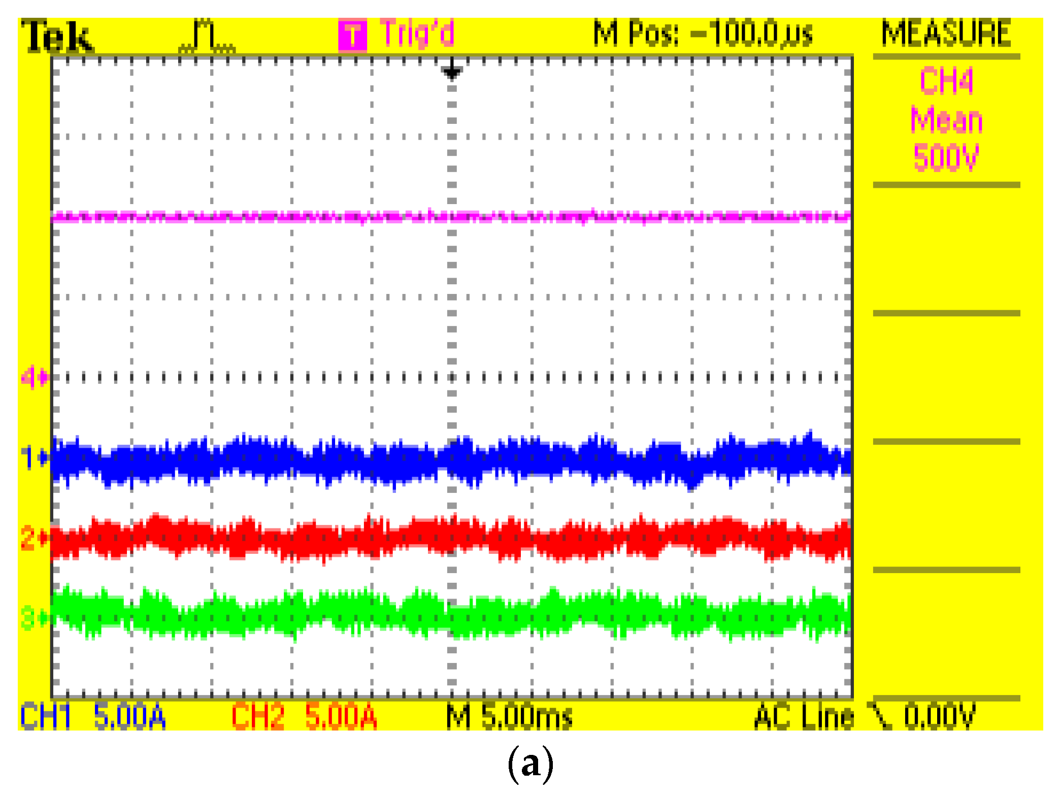
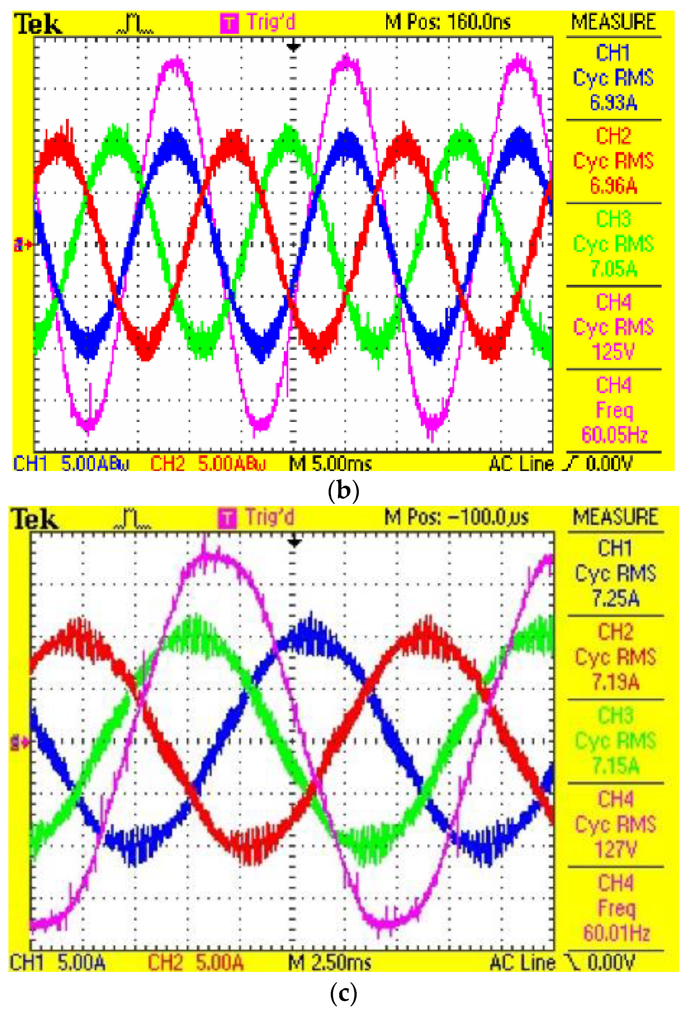
Figure 13 validates the DC-link voltage control, and the current control from the grid-side converter. Figure 13a highlights the controlled DC-link voltage, and the minimum required active power to ensure the power balance between AC and DC sides (i.e., supply the inherent power losses of converter). Figure 13b,c show the active and reactive power injection into the grid. The waveforms of Figure 13b show the power factor close to one, and the THD of currents approximately to 4%; the PCC voltage magnitude is 125 V, and THDv is about 2%. Figure 13c shows the injection of the capacitive reactive power, with a power factor of 0.82 and THDi close to 4%. One can see that the PCC voltage magnitude increases to 127 V, and the THDv is about 2%. The current magnitudes can be seen in Figure 13 itself.
5.3. Generator-Side Control
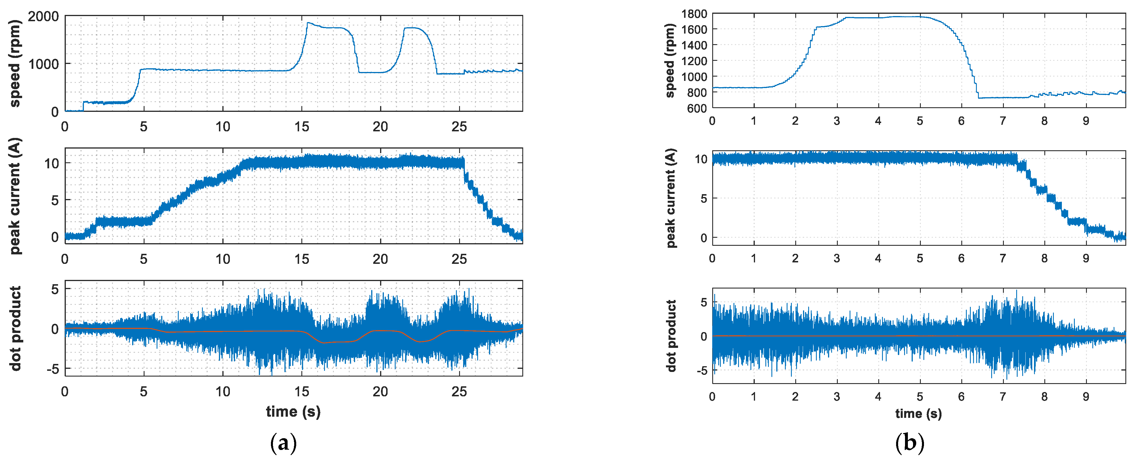
To validate the generator-side control loop that guarantees the orthogonal spatial angle orientation during transient, which is a major requirement for accurate torque control, the synchronous generator runs under speed variation (i.e., torque disturbance). In order to test and evaluate the stator current tracking and the decoupling between the flux and torque, the control scheme without orthogonal spatial angle orientation control is first considered, and then it is considered with the proper angle control loop. Figure 14 shows, from top to bottom, the shaft speed; the peak value of the stator current; and the instantaneous (blue curve) and average (red curve) values of the dot product, dp, that evaluates the capacity for cancelling the reluctance torque (13).
So, Figure 14a represents the first condition, and it shows that the average dot product time-variation depends on the wind speed. Even with the stator peak current tracking its reference, and being constant between 12 and 25 s, the torque control is not effective because the reluctance torque is not cancelled (T1 and T2 from (18) and (19)). It can be observed from the average value of dp that is not zero, even in steady-state, which indicates phase displacement related to the back-EMF. On the other hand, Figure 14b shows the proper torque-control operation with the orthogonal spatial angle orientation control loop of Figure 8, in which the average value of the dot product, dp, is kept at zero. This guarantees the torque control by regulating the stator current, which ensures proper dynamic stiffness against the rejection of external torque disturbances. The stator current reference is reduced after the instant of 7 s, the stator current follows it correctly, and the average value of dp remains zero. The result of Figure 14b is a zoom-in-view for the detailed visualization of the transients.
6. Conclusions
This paper proposed the control scheme conceived in a natural abc-frame for wind-power system based on a permanent magnet synchronous generator. For the grid-side converter, the multifunctionality of compensating the electrical disturbances of load current under distorted and asymmetrical grid voltage was considered. Moreover, experimental results of DC-link voltage regulation and active/reactive power injection were shown. For the generator-side converter, the torque control was tested under wind speed variation through simulation and experimental results.
The proposed control in the abc-frame of Figure 1 can be interpreted in terms of the basic torque control requirements: (1) the constant field flux; (2) the independently controlled stator current; and (3) the orthogonal spatial angle between the flux axis and the magnetomotive force. The first requirement is met due to the permanent magnet poles of a PMSG that produces constant field flux. The stator current closed-loop control imposes the amplitude of the phase stator currents, matching the requirement (2). The third requirement, the orthogonal spatial angle orientation control, imposes the required field orientation. This is achieved by regulating the instantaneous dot-product of and to a zero mean value. So, one concludes that the generator-side control is developed over these three basic requirements for proper torque control.
Author Contributions
Conceptualization, I.D.L.d.C., D.I.B., S.I.S.J. and L.M.F.M.; methodology, I.D.L.d.C., D.I.B.; software, I.D.L.d.C.; validation, I.D.L.d.C., D.I.B. and L.M.F.M.; formal analysis, I.D.L.d.C., D.I.B., S.I.S.J. and L.M.F.M.; investigation, I.D.L.d.C., D.I.B., S.I.S.J. and L.M.F.M.; resources, I.D.L.d.C., D.I.B. and L.M.F.M.; data curation, I.D.L.d.C., D.I.B., S.I.S.J. and L.M.F.M.; writing—original draft preparation, I.D.L.d.C., D.I.B., S.I.S.J. and L.M.F.M.; writing—review and editing, I.D.L.d.C., D.I.B., S.I.S.J. and L.M.F.M.; visualization, I.D.L.d.C., D.I.B., S.I.S.J. and L.M.F.M.; supervision, L.M.F.M., S.I.S.J. and D.I.B.; project administration, L.M.F.M. and D.I.B.; and funding acquisition, D.I.B. All authors have read and agreed to the published version of the manuscript.
Funding
This study was financed in part by the Coordenação de Aperfeiçoamento de Pessoal de Nível Superior—Brasil (CAPES)—Finance Code 001. The APC was funded in part by Pró-Reitoria de Pesquisa (PRPq) da Universidade Federal de Minas Gerais, in part by FAPEMIG under the grant PPM-00587-18, and in part by Worldwide Universities Network—Research Development Fund 2021.
Institutional Review Board Statement
Not applicable.
Informed Consent Statement
Not applicable.
Acknowledgments
The authors acknowledge Victor Mendes from UFMG for providing the research facilities of Laboratory of Energy Conversion and Control (LCCE-UFMG) and the test bench to obtain the experimental results.
Conflicts of Interest
The authors declare no conflict of interest.
References
- U.S. Department of Energy’s Office of Energy Efficiency and Renewable Energy. Wind Energy Technologies Office. 2022. Available online: https://www.energy.gov/eere/wind/how-distributed-wind-works (accessed on 29 July 2022).
- Majout, B.; Bossoufi, B.; Bouderbala, M.; Masud, M.; Al-Amri, J.F.; Taoussi, M.; El Mahfoud, M.; Motahhir, S.; Karim, M. Improvement of PMSG-Based Wind Energy Conversion System Using Developed Sliding Mode Control. Energies 2022, 15, 1625. [Google Scholar] [CrossRef]
- Okedu, K.E. Augmentation of DFIG and PMSG Wind Turbines Transient Performance Using Different Fault Current Limiters. Energies 2022, 15, 4817. [Google Scholar] [CrossRef]
- Novotny, D.W.; Lipo, T.A. Vector Control and Dynamics of AC Drives; Oxford University Press: Oxford, UK, 1996. [Google Scholar]
- Zhao, Y.; Wei, C.; Zhang, Z.; Qiao, W. A Review on Position/Speed Sensorless Control for Permanent-Magnet Synchronous Machine-Based Wind Energy Conversion Systems. IEEE J. Emerg. Sel. Top. Power Electron. 2013, 1, 203–216. [Google Scholar] [CrossRef]
- Niu, F.; Wang, B.; Babel, A.S.; Li, K.; Strangas, E.G. Comparative Evaluation of Direct Torque Control Strategies for Permanent Magnet Synchronous Machines. IEEE Trans. Power Electron. 2016, 31, 1408–1424. [Google Scholar] [CrossRef]
- Tsai, M.-F.; Tseng, C.-S.; Lin, B.-Y. Phase Voltage-Oriented Control of a PMSG Wind Generator for Unity Power Factor Correction. Energies 2020, 13, 5693. [Google Scholar] [CrossRef]
- ABB. ABB Low Voltage Wind Turbine Converters ACS800. 2019. Available online: https://library.e.abb.com/public/6bc97383c44f5098c1257bf6004491db/ACS800%20low%20voltage%20wind%20turbine%20converters_lowres.pdf (accessed on 29 July 2022).
- Yip, S.Y.; Che, H.S.; Tan, C.P.; Chong, W.T. A Look-up Table Model Predictive Direct Torque Control of Permanent Magnet Synchronous Generator based on Vienna Rectifier. IEEE J. Emerg. Sel. Top. Power Electron. 2020, 8, 1208–1222. [Google Scholar] [CrossRef]
- Niu, F.; Huang, X.; Ge, L.; Zhang, J.; Wu, L.; Wang, Y.; Li, K.; Fang, Y. A Simple and Practical Duty Cycle Modulated Direct Torque Control for Permanent Magnet Synchronous Motors. IEEE Trans. Power Electron. 2019, 34, 1572–1579. [Google Scholar] [CrossRef]
- Montero, M.I.M.; Cadaval, E.R.; Gonzalez, F.B. Comparison of Control Strategies for Shunt Active Power Filters in Three-Phase Four-Wire Systems. IEEE Trans. Power Electron. 2007, 22, 229–236. [Google Scholar] [CrossRef]
- Costa, I.D.L.; Brandao, D.I.; Matakas Junior, L.; Simões, M.G.; Morais, L.M.F. Analysis of Stationary- and Synchronous-Reference Frames for Three-Phase Three-Wire Grid-Connected Converter AC Current Regulators. Energies 2021, 14, 8348. [Google Scholar] [CrossRef]
- Bubshait, A.S.; Mortezaei, A.; Simões, M.G.; Busarello, T.D.C. Power Quality Enhancement for a Grid Connected Wind Turbine Energy System. IEEE Trans. Ind. Appl. 2017, 53, 2495–2505. [Google Scholar] [CrossRef]
- Campos, M.F.C.; Brandao, D.I.; Mendes, V.F.; Morais, L.M.F.; Seleme, S.I. Control of a PMSG based wind power system using abc-frame under distorted and asymmetrical voltage conditions. In Proceedings of the IEEE Southern Power Electronics Conference, Puerto Varas, Chile, 4–7 December 2017. [Google Scholar]
- IEEE STD 1547; IEEE Standard for Interconnection and Interoperability of Distributed Energy Resource with Associated Electric Power Systems Interface. IEEE Standards Coordinating Committee: Hoboken, NJ, USA, 2018.
- Bonaldo, J.P.; Paredes, H.K.M.; Pomilio, J.A. Control of Single-Phase Power Converters Connected to Low-Voltage Distorted Power Systems with Variable Compensation Objectives. IEEE Trans. Power Electron. 2016, 31, 2039–2052. [Google Scholar] [CrossRef] [Green Version]
- Heier, S. Grid Integration of Wind Energy: Onshore and Offshore Conversion Systems; John Wiley & Sons: Hoboken, NJ, USA, 2014. [Google Scholar]
- Santos, G.V.; Cupertino, A.F.; Mendes, V.F.; Seleme, S.I. Interconnection and damping assignment passivity-based control of a PMSG based wind turbine for maximum power tracking. In Proceedings of the IEEE International Symposium on Industrial Electronics, Buzios, Brazil, 3–5 June 2015. [Google Scholar]
- Singh, M.; Khadkikar, V.; Chandra, A. Grid synchronisation with harmonics and reactive power compensation capability of a permanent magnet synchronous generator-based variable speed wind energy conversion system. IET Power Electron. 2011, 4, 122–130. [Google Scholar] [CrossRef] [Green Version]
- Rossetto, L.; Malesani, L.; Tenti, P.; Buso, S.; Pollmann, A. Fully digital control of a three phase UPS by VECON integrated controller. In Proceedings of the IAS ’95 Conference Record of the 1995 IEEE Industry Applications Conference Thirtieth IAS Annual Meeting, Orlando, FL, USA, 8–12 October 1995. [Google Scholar]
- Brandao, D.I.; Paredes, H.K.P.; Costabeber, A.; Marafao, F.P. Flexible active compensation based on load conformity factors applied to non-sinusoidal and asymmetrical voltage conditions. IET Power Electron. 2016, 2, 356–364. [Google Scholar] [CrossRef]
- Holmes, D.G.; Lipo, T.A. Pulsewidth Modulation for Power Converters—Principle and Practice; IEEE Press Series on Power Engineering; Wiley: Hoboken, NJ, USA, 2003. [Google Scholar]
- Matakas, L. Controller Implementation for Three-Phase Power Converters without Coordinate Transformations: Geometric Analysis Based on Space Vectors Livre Docência; Universidade de São Paulo: São Paulo, Brazil, 2012. (In Portuguese) [Google Scholar]
- Boldea, I. Variable Speed Generators; CRC Press: Boca Raton, FL, USA, 2006. [Google Scholar]
- Merabet, A.; Tanvir, A.A.; Beddek, K. Speed control of sensorless induction generator by artificial neural network in wind energy conversion system. IET Renew. Power Gener. 2016, 10, 1597–1606. [Google Scholar] [CrossRef]
- Weizhe, Q. Torque Pulsations Minimization in PM Synchronous Motor Drive. Master’s Thesis, National University of Singapore, Singapore, 2004. [Google Scholar]
- Padua, M.S.; Deckmann, S.M.; Marafao, F.P. Frequency-adjustable positive sequence detector for power conditioning applications. In Proceedings of the 2005 IEEE 36th Power Electronics Specialists Conference, Dresden, Germany, 16 June 2005. [Google Scholar]
- Tenti, P.; Paredes, H.K.M.; Matavelli, P. Conservative Power Theory, a Framework to Approach Control and Accountability Issues in Smart Microgrids. IEEE Trans. Power Electron. 2011, 26, 664–673. [Google Scholar] [CrossRef]
- Mattavelli, P.; Buso, S. Digital Control in Power Electronics; Morgan & Claypool: San Rafael, CA, USA, 2006. [Google Scholar]
- Holmes, D.G.; Lipo, T.A.; McGrath, B.P.; Kong, W.Y. Optimized Design of Stationary Frame Three Phase AC Current Regulators. IEEE Trans. Power Electron. 2009, 24, 2417–2426. [Google Scholar] [CrossRef]
Figure 1.
(a) The considered wind-power system with three-phase, three-wire, back-to-back converter; (b) control scheme of the generator-side converter; and (c) control scheme of the grid-side converter.
Figure 1.
(a) The considered wind-power system with three-phase, three-wire, back-to-back converter; (b) control scheme of the generator-side converter; and (c) control scheme of the grid-side converter.


Figure 2.
Power coefficient () versus tip-speed ratio ( ) versus pitch angle ( ).

Figure 3.
Mechanical speed versus generated power for several different wind speeds: v1 < v2 < v3 < v4 < v5.
Figure 3.
Mechanical speed versus generated power for several different wind speeds: v1 < v2 < v3 < v4 < v5.

Figure 4.
(a) Three-phase, three-wire voltage source inverter and (b) its equivalent circuit.

Figure 5.
Control strategy with system minus-one controllers and optimal zero-sequence method.

Figure 6.
Equivalent circuit of the generator stator.

Figure 7.
Vector diagram of a PMSG on synchronous reference frame.

Figure 8.
Closed-loop control model diagram for the generator-side converter. PI controllers were considered for all control loops.
Figure 8.
Closed-loop control model diagram for the generator-side converter. PI controllers were considered for all control loops.

Figure 9.
Closed-loop control model diagram for the grid-side converter.

Figure 10.
System behavior under wind-speed variation.

Figure 11.
Active power injection and non-active current compensation.

Figure 12.
Test bench of the back-to-back converter.

Figure 13.
(a) DC-link voltage control, (b) active power injection, and (c) reactive power injection. Current waveform [CH1, CH2, CH3-5 A/div], DC-link voltage waveform [CH4-250 V/div], and AC voltage waveform [CH4-50 V/div].
Figure 13.
(a) DC-link voltage control, (b) active power injection, and (c) reactive power injection. Current waveform [CH1, CH2, CH3-5 A/div], DC-link voltage waveform [CH4-250 V/div], and AC voltage waveform [CH4-50 V/div].


Figure 14.
Evaluation of the orthogonal spatial angle orientation control during wind speed variation. (a) Without angle control loop; (b) with angle control loop.
Figure 14.
Evaluation of the orthogonal spatial angle orientation control during wind speed variation. (a) Without angle control loop; (b) with angle control loop.


Table 1.
Parameters of the system.
| AC Grid Parameters |
|---|
| Vac= 127 V, f = 60 Hz, Lg = 500 µH, rg = 0.05 Ω |
| Generator parameters |
| S= 3 kVA, Vt = 220 V, Ls = 5.1 mH, Rs = 1.6 Ω,𝑃𝐹= 0.8,𝑁pp= 4,𝜙𝑝𝑚= 0.48Wb,𝑛𝑛𝑜𝑚= 1800rpm, *𝐽𝑡𝑔= 5.64 × 10⁻⁴ kg·m2,𝐵= 2.07 × 10⁻³ N·m·s |
| Converter Parameters |
| 𝑉𝑑𝑐= 500 V, C𝑑𝑐= 3.06 mF,𝐿𝑓= 4 mH,𝑟𝑓= 0.16 Ω,𝑓𝑠= 12 kHz,𝑓𝑠𝑤= 12 kHz (simulation),𝑓𝑠𝑤= 6 kHz (experimental) |
| Sensor Gain Parameters |
| 𝐾𝑖= 1/35,𝐾𝑖𝑠= 1/35,𝐾𝑣𝑎𝑐= 1/311,𝐾𝑣𝑑𝑐= 1/500,𝐾𝜔= 1 |
Turbine + generator.
Table 2.
Parameters of the controllers.
| Controller | fc | PM | Kp | Ki | ||||||
|---|---|---|---|---|---|---|---|---|---|---|
| Cis(s) | 1 kHz | 60° | 1.9 | 76910 | ||||||
| Cω(s) | 40 Hz | 60° | 0.08 | 12.26 | ||||||
| Cθ(s) | 90 Hz | 90° | 0.01 | 50 | ||||||
| Ci(s) | 1.2 kHz | 60° | 1.8 | 1° | 5° | 7° | 11° | 13° | 19° | ωb |
| 94.8 | 89.1 | 83.4 | 66.3 | 54.9 | 9.3 | 6.28 rad | ||||
| Cv(s) | 10 Hz | 60° | 7.63 | 276.7 | ||||||
Publisher’s Note: MDPI stays neutral with regard to jurisdictional claims in published maps and institutional affiliations. |
© 2022 by the authors. Licensee MDPI, Basel, Switzerland. This article is an open access article distributed under the terms and conditions of the Creative Commons Attribution (CC BY) license (https://creativecommons.org/licenses/by/4.0/).
Share and Cite
MDPI and ACS Style
da Costa, I.D.L.; Brandao, D.I.; Seleme, S.I., Jr.; Morais, L.M.F. Torque Control for PMSG-Based Wind-Power System Using Stationary abc-Reference Frame. Energies 2022, 15, 8060. https://doi.org/10.3390/en15218060
AMA Style
da Costa IDL, Brandao DI, Seleme SI Jr., Morais LMF. Torque Control for PMSG-Based Wind-Power System Using Stationary abc-Reference Frame. Energies. 2022; 15(21):8060. https://doi.org/10.3390/en15218060
Chicago/Turabian Styleda Costa, Israel Divan Lopes, Danilo Iglesias Brandao, Seleme Isaac Seleme, Jr., and Lenin Martins Ferreira Morais. 2022. "Torque Control for PMSG-Based Wind-Power System Using Stationary abc-Reference Frame" Energies 15, no. 21: 8060. https://doi.org/10.3390/en15218060
Note that from the first issue of 2016, this journal uses article numbers instead of page numbers. See further details here.