
Electrical Generators for Large Wind Turbine: Trends and Challenges

GREAH, Le Havre Normandie University, 76600 Le Havre, France
*
Author to whom correspondence should be addressed.
Energies 2022, 15(18), 6700; https://doi.org/10.3390/en15186700
Submission received: 19 July 2022
/
Revised: 3 September 2022
/
Accepted: 6 September 2022
/
Published: 13 September 2022
(This article belongs to the Special Issue Trends and Innovations in Wind Power Systems)
Abstract
:This paper presents an overview of the emerging trends in the development of electrical generators for large wind turbines. To describe the developments in the design of electrical generators, it is necessary to look at the conversion system as a whole, and then, the structural and mechanical performances of the drive train need to be considered. Many drive train configurations have been proposed for large wind turbines; they should ensure high reliability, long availability and reduced maintainability. Although most installed wind turbines are geared, directly driven wind turbines with permanent magnet generators have attracted growing interest in the last few years, which has been in parallel to the continuous increase of the per unit turbine power. The aim of this work is to present the recent commercial designs of electrical generators in large wind turbines. Both the strengths and weaknesses of the existing systems are discussed. The most emerging technologies in high-power, low-speed electrical generators are investigated. Furthermore, a comparative analysis of different electrical generator concepts is performed, and the generators are assessed upon a list of criteria such as the mass, cost, and mass-to-torque ratio. Within the framework of these criteria, it may help to determine whether the electrical generator is technically feasible and economically viable for high-power wind turbines. Finally, this review could help to determine suitable generators for use in large and ultra-large wind energy systems.
1. Introduction
To meet the fast-growing energy demand, the current research in wind energy is discussing the idea of upscaling the wind turbines. A large wind turbine leads to a high net power rating and low average Levelized Cost Of Energy LCOE (The LCOE is an indicator taking into consideration the capital cost, operation and maintenance costs (O&M) and the annual energy production). Indeed, with higher hub altitudes, large turbines capture stronger and more stable wind compared to small and medium turbines [1]. Furthermore, the power generated by a wind turbine is proportional to its swept area, so longer blades catch the wind more efficiently. An offshore wind turbine seems to be a good solution to increase the wind power exploitation with lower costs. Not surprisingly, the average size of offshore wind turbines has been increasing over the last several years. The growing interest in large wind turbines generates new technical and economical challenges [2]. Upscaling a turbine can prove quite challenging [3]. In particular, the energy conversion system mass increases faster than the power rating; thus, the drive train issues are of interest. For this reason, it is interesting to consider the scaling effects on the nacelle, tower and foundations. In addition, while attempting to reduce the cost of the energy, multi-megawatts wind turbines must guarantee high availability (Availability: ratio of the total number of hours during a certain period, excluding the number of hours that the wind turbine generator system could not be operated due to maintenance or fault situations, to the total number of hours in the period, expressed as a percentage (IEC 60050-415:1999) [4]), reliability (Reliability: the ability to perform as required, without failure, for a given time interval, under given conditions (IEC 60050-192:2015) [5]) and serviceability (Serviceability: conditions relating to the boundaries of normal service criteria (IEC 60050-415:1999) [4]) [6,7].
The drive train, which represents the direct link between the rotor shaft and the electrical generator, is subject to high dynamic loads (wind loads, electrical load) [3,8,9]. Therefore, taking into account the mechanical and structural performances of the drive train is crucial in the design of a reliable and efficient electrical generator [10,11,12,13,14,15]. In the conventional wind turbines, most of the drive trains had a gearbox and high-speed induction generator. In contrast, with the considerable increase in the average power of wind turbines, direct-drive low-speed generators are gaining attention due to some technical and economic constraints. According to the rotation speed, wind turbines can operate either at fixed or variable speeds. In the fixed speed concept, there is only one wind speed on the turbine’s power curve at which the tip–speed ratio is optimum. Therefore, unless the wind regime at a particular site is highly peaked at that optimal wind speed, the wind turbine will generally be operating off of its optimum performance. Consequently, this system is aerodynamically less efficient. The variable speed concept enables the rotor blades to operate at its optimal tip–speed ratio (TSR) by adapting its rotation speed to the wind speed, so that more wind power is extracted. The variable speed drive can operate efficiently over a wider range of wind speeds and can exhibit more efficient energy extraction at the lower wind speeds. Furthermore, adapting the rotation speed of the rotor to the wind speed not only increases the efficiency of the drive train but also helps to absorb the power fluctuation caused by the turbulence of the wind. In the fixed speed concept, a high-speed induction generator driven through a mechanical multi-stage gearbox is used; hence, it can be directly connected to the grid. On the contrary, in the variable speed concept, the drive train would either be geared (multi-stage or single-stage) or gearless (direct-drive), and a frequency converter can be interposed between the generator and the grid in order to regulate the generator’s speed. In the variable speed concept, the speed range around the synchronous speed is nearly the same as the power through the converter. Therefore, the variable speed concept can be broadly categorized into two categories based on the power rating of the converter: the partially-rated converter-based system (limited range variable speed) and the fully-rated converter-based system (wide range variable speed).
As technology progresses, offshore direct-drive large wind turbines (over 10 MW) are gaining popularity [2,16]. The gearless technology has the advantage that there is no gearbox. Usually, gearboxes incur additional cost and potential failure. Despite the fact that gearbox failure is not the most common, it has high downtime [17,18,19]. Thus, a direct-coupled generator would improve the reliability and efficiency of wind turbine especially in the offshore environment.
This paper reviews the state of the art of under construction, existing and prototypes of electrical generators used in large multi-megawatts wind turbines, and it also discuses future development trends. Firstly, after a short historical background, the current status of wind energy is presented. Furthermore, the wind energy power is described in order to establish a context for understanding the contemporary wind energy industry. Then, reasons behind the increasing capacity of wind turbines are discussed. Up-scaling wind turbines brings many challenges, including mechanical, electrical and manufacturing aspects. Those challenges and some projects to tackle them are exposed. Secondly, features, advantages and drawbacks of indirect drive train wind turbines are discussed. Finally, in the last section, gearless large wind turbines are presented. More focus is on the conventional and the most widely adopted electrical generators. The different topologies of generators used for ultra-large wind turbine applications are reviewed. Those generators are assessed with criteria such as mass to torque ratio, mass, cost and losses. Advantages and drawbacks of each configuration are also discussed.
2. Historical Background and Wind Turbine Technologies
2.1. Wind Power
A wind turbine transforms first the kinetic energy in the wind into rotational mechanical energy next to electrical energy. A turbine could be divided into three main parts including the tower, the rotor and the nacelle. The tower is the supporting structure of the wind turbine. The rotor, referring to the blades and the hub, transfers the mechanical energy to the nacelle. Depending on the rotor orientation, two types of wind turbines could be distinguished: upwind and downwind. In the upwind machine, the rotor is facing the wind, whereas in the downwind machine, the rotor is placed on the lee side of the tower (see Figure 1). The nacelle houses the electrical generator, gearbox (if present), controller and brake. The components of the nacelle are to serve as converters; they transform the rotational energy from the rotor hub to electrical energy.
The total power delivered by a wind turbine differs with respect to the wind speed and characteristic power performance curve of this turbine. The amount of the power extracted by the wind turbine is proportional to its swept area A (m2) (() r is the radius of the swept area, which represents also the blade’s length), the air density (kg/m3) (i.e., mass per unit of volume) and to the cube of the wind velocity (m/s) reduced by power coefficient according to the formula:
where (W) is the available power in wind, is the power coefficient, which is a measure of aerodynamic efficiency of extracting energy from the wind, and z (m) denotes the altitude above the sea. and are the tip–speed ratio and the pitch angle (will be further detailed). It should be noted that the air density varies as a function of temperature and pressure in compliance with the perfect gas law. Since both pressure and temperature depend on the altitude above the sea level, the air density can be expressed by:
where is the standard sea level atmospheric density (1.225 kg/m3);
R is the specific gas constant for air (287.05 J/kg/K );
g is the gravity constant (9.81 m.s−2);
T is the temperature (K);
z is the altitude above sea level (m).
The power coefficient represents the aerodynamic efficiency of the wind turbine; it is a measurement of how efficiently the wind turbine extracts the wind energy (in the airflow). This coefficient depends on the aerodynamic airfoil shape, chord length, blade length, and blade twist. Furthermore, the overall wind turbine efficiency depends on the aerodynamic, mechanical (gearbox, shaft bearing support) and electrical (generator, converter) inefficiencies [20]. The theoretical maximum value of the power coefficient is defined by Betz’s Law, which states that the maximum captured power by the wind turbine could not exceed 16/27 (59.3%) of the available wind power wind [20]. However, is usually less than 45%. This significant reduction in the power coefficient is due to the presence of aerodynamic losses in the wind turbine systems such as the blade tips, blade roots, and wake losses [21]. Fortunately, advances in technology allow modern wind turbines to operate near to the theoretical limit. could be expressed as a function of the tip–speed ratio and the pitch angle ; the curve relating those coefficients could be best obtained from direct measurements of the turbine in operation [22]. The TSR refers to the ratio between the rotor tip speed (linear speed of the rotor tip) and the wind speed:
where (rad/s) () is rotor tip angular velocity, f (Hz) is the blade frequency, and is the rotational speed of the blades (speed of the blades ends). It is therefore essential to calculate the optimal tip speed in order to maximize the turbine’s efficiency [23]. For a given wind turbine, the power coefficient depends on both the tip speed ratio and pitch angle. The characteristic curves in Figure 2 illustrate the interrelationship between and for different values of pitch angle. For a particular value of , the power coefficient increases with the decrease of , and thus, the maximum of the power coefficient is achieved for zero pitch angle (0 degree). For a given pitch angle, it could be seen that the increases with the increase in the tip–speed ratio until it reaches its maximum at , and then, it starts to decline steadily with a further increase in .
The efficiency of the wind turbine is not constant, and it depends on the wind speed. Thus, the power curve could be split into four operation regions with respect to the wind speed.
- Region I: when the wind speed is less than the threshold speed, the torque is insufficient to overcome the power loss (i.e., losses due to drag at the blade, friction losses in the gearbox and in bearings, electrical losses with the generator); as a consequence, no power is generated below the cut-in speed.
- Region II: (variable speed region) when the wind speed exceeds the cut-in speed (around 3–5 m/s depending the turbine design), there is a sufficient torque for rotation; thus, the turbine starts to generate electricity. In this operational mode, which accounted for more than 50% of the yearly energy capture for a typical modern wind turbine [24], the power produced by the wind turbine increases proportionally to the cubic power of the wind speed (as is expected from (1)). The power curve reaches a peak around the so-called rated output speed (12–14 m/s). Above the rated output speed, the power generated remains unchanged at its permanently permissible maximum (known as rated power); it is kept almost constant by different control options. The pitch angle is usually controlled to keep the wind turbine operating at the peak of the –TSR–pitch surface [24] and to limit the power when the speed exceeded the rated wind speed to avoid structural failure [25].
- Region III: (constant speed region) at which the wind speed is between rated speed and cut out speed (around 25 m/s). The rotor speed is held constant above the rated speed by the regulation of the angle of attack (See Figure 2). This ensures limited aerodynamic power in this region despite much more available wind energy.
- Region VI: When the wind speed exceeds the cut-out speed, the wind turbine is shut down.
2.2. Historical Background
During the last decade, various conversion systems for wind turbines have been developed. The earlier wind turbines, with small capacities, were equipped with a constant-speed conversion system. In such a system, a high-speed Squirrel Cage Induction Generator (SCIG) is connected to the turbine’s main shaft through a three-stage gearbox on one hand, and on the other hand, it is directly connected to the grid. It operates slightly above the synchronous speed. Moreover, it is possible to use a two-speed pole-changing generator; most such generators have four or six poles (1500/1000 rpm). Unlike the dual-speed technology, the wind turbine will be often operating off its optimal performances due to the wind regime. This configuration was rejected due to its limitations. First, it presents low reliability due to the presence of the gearbox. Then, conversion efficiency cannot be optimized; just slight variations of the rotor shaft speed is allowed. After all, the turbulence of the wind may cause torque pulsations, which affect not only the power quality but also the mechanical stress [26,27]. Finally, fluctuations of the transmitted power could reach 20% of the nominal power [28]. To overcome limitations of the fixed speed system, an ameliorated version based on induction generators coupled to variable resistance has been developed. This configuration is known as limited-variable speed, OptiSlip or the dynamic rotor resistance concept. An OptiSlip conversion system may operate over a range of rotor speed; however, the variable speed range of the induction generator is limited by the size of the rotor resistor. Then, it is possible to achieve a range of % above the synchronous speed. This concept not only offers a control flexibility but also allows extracting more energy compared to the fixed speed concept. Nevertheless, there is still a lack of capacity regarding the electrical losses (heat in rotor resistance) and the power quality, and it also excluded more advanced power control. In order to enhance the efficiency of the system and avoid the costly slip rings, optical coupling could be used. It consists of mounting an additional rotor resistance on the rotor shaft; the rotor resistance is controlled using an optically controlled converter (OptiSlip concept) [29].
Variable-speed wind energy conversion systems have been proposed to track the changes in wind speed and maintain optimal power generation. In such a configuration, a power converter is required. The converter is used to control the rotor speed and frequency. It is possible to add a full rated power converter between the SGIG and the grid; however, this solution is not economically attractive (full rated converter and gearbox). In fact, reducing the overall cost can be completed either by down scaling the converter (partial scale converter) and/or by removing the gearbox (full scale converter). In the first case, a high-speed Doubly-Fed Induction Generator (DFIG) is used, and the stator of the DFIG is connected directly to the grid (50/60 Hz), while the rotor is connected through slip rings and brushes to the converter and then to the grid. The converter handles, therefore, a fraction of the generator power. A common speed range of % gives a power converter rated at 30% of the generator power. The converter not only performs the reactive power compensation but also guarantees smother grid connection. As it can be noticed, this configuration offers a wider speed range compared with the OptiSlip concept. Nevertheless, the presence of the gearbox induces audible noise and high overall wind turbine cost, including manufacturing and regular maintenance cost. An additional maintenance cost is introduced due to the presence of the slip rings and brushes and carbon brushes wear out, which should be changed at least once a year [30]. As a consequence, manufacturers do not commonly use DFIG in ultra-large powers. To sum up, the drive train layout based on an induction generator offers a simple, robust, reliable, and economical solution, but they present low availability and reliability due to the presence of the gearbox. Indirect drive train concepts for a large wind turbine will be explained in more detail in Section 4. In the second case, a low-speed Permanent Magnet Synchronous Generator (PMSG) or Electrically Excited Synchronous Generator (EESG) is directly coupled to the turbine’s rotor, whereas a full-scale frequency converter is needed. This concept is the most common conversion system in a multi-megawatts wind turbine; it offers a significant energy yield, with high availability and reliability. In contrast, generators in gearless drive trains suffer from many drawbacks such as a heavy machine (considering the active and the supporting structural part), and they are also more costly than the conventional generators. Thus, a hybrid drive train (also know as a semi-direct or multibrid drive train) has been introduced to avoid the drawbacks of both gear and gearless conversion systems. In this concept, only a single-stage planetary gearbox (sometimes two-stages) is used with a medium-speed PMSG, and the gear ratio is about only 10. A single-stage gearbox is lighter and more reliable than a multi-stage one. In addition, unlike PMSG in a direct-drive wind turbine, which requires rather a large diameter generator, the PMSG in a multibrid system is relatively smaller and cheaper. Both the generator and the gearbox have approximately the same size, leading to a more balanced drive train arrangement [31]. Consequently, improved performances, structural economy and higher efficiency could be achieved. The direct and semi-direct drive train will be dealt with in more detail in Section 5.
3. Global Wind Energy Development
3.1. Global Market Status
From 2015 to 2019, global renewable energy generation capacity is increasing. The latest available data show growth of 176 GW in 2019 [32]. At the end of 2020, the global annual renewable generation capacity reached nearly 2800 GW [33]. Although the hydropower accounted for the largest installed renewable energy in 2020 with 20 GW rises compared to 2019 [33], the solar and wind energy continue to lead renewable generation capacity expansion with an augmentation of 126 GW and 111 GW, respectively [33]. The renewable energy sector has quickly grown due to the reduction in costs, which is a normal consequence of the tremendous potential offered by those energies, and the ever-increasing awareness of the importance of this kind of energies (policy development, supporting mechanisms). Many countries try to widen the geographical support of some renewable energies to meet the rapid rise in the electricity demand and moderate the cost of energy; wind energy seems to be one of the competitive ways to clean energy generation. Solar power faces limitations, since it is linked to a region’s specifications. Hydro-power energy is considered to be fully developed [34]. The wind power is the second largest renewable energy, behind hydro-power energy (see Figure 3). Its market is increasing all over the world, and it showed one of the largest annual increases in 2020 despite the COVID-19 pandemic crisis. Furthermore, over the last decade (2010–2019), the cost of the KiloWatt-hour (kWh) for onshore and offshore has declined about 40% and 30%, respectively [35]. The global Levelized Cost Of Electricity (LCOE) from onshore wind has been driven down by 10% from the second half of 2018 to the same period in 2019, which is nearly 50% lower than in the second half of 2009. For offshore wind, the global LCOE plunged by 60% in 7 years, from nearly USD 230 per MWh on the second half of 2012 to USD 78 per MWh in 2019 [36].
The LCOE does not depend solely on the project cost (e.g., costs of development, construction, equipment, operation and maintenance) but also on the wind resources, and then, it varies greatly by country, by region and by farm (size of the farm, the distance between the turbines, etc. [37]). The improvements in wind turbine technology (e.g., higher capacity factor (representing the average power output from a wind farm divided by its maximum power capability on an annual basis. It mainly depends on two factors: the quality of the wind resources where the wind farm is sited; the turbine and balance-of-plant technology used), higher efficiency, reduced cost of manufacturing, lower operations and maintenance costs) and the downward trend in the cost of the wind energy-generated new wind markets. The statistics show that the biggest companies that invest in renewable energy concentrate on the wind power; Figure 4 illustrates how investment in wind energy dominates over the other renewable energy technologies.
According to the Global Wind Energy Council (GWEC), more than 90 GW of new wind power was installed in 2020 [38]. The global new installed wind capacity expanded by 53% growth in 2020 (86.9 GW in onshore and 6.1 GW in offshore) compared to 2019 [38], bringing the total installed capacity to 743 GW. Asia driven by China, the largest regional market, accounted for 60% of the global new installations at the end of 2020 [38]. It is followed by Europe, North America, Latin America and Africa and the Middle East with 16%, 18%, 5%, and 1% of the additional wind capacity, respectively [38].
3.2. Offshore Wind Turbine Technology
Offshore wind power generation is one of the most promising technologies not only to increase the power generation with acceptable cost but also to manage the public resistance due to the visual pollution. Although the majority of the actual wind power installed capacity is land-based, the offshore wind energy is expected to keep expending in future years [39]. Offshore wind energy offers an expanded area of stronger (higher speeds) and consistent wind with less visual pollution and reduced noise impact. Advanced wind turbines operate under extreme weather conditions (IEC S) (International Electrotechnical Commission) is the world’s leading organization that prepares and publishes International Standards for all electrical, electronic and related technologies [40]. The IEC for wind turbines address certification procedures, design, requirement, engineering integrity, measurement techniques, and test procedures [41]) in high wind intensity sites (IEC I) [40,41]. Similarly, new technologies offer not only a better offshore wind farms siting and sizing but also a boosted capacity factor. As an example, floating foundations enable installation in deeper water and thus more attractive energy resources (high wind intensity). In addition, improving the primary energy efficiency may be possible by adapting large wind turbines (longer blades, higher tower) to offshore environments (e.g., dynamics and loads of the system, storm condition). As a consequence, floating multi-megawatt wind turbines may be the suitable solution for the next generation of offshore wind turbines. Despite the fact that there are many environmental restrictions in offshore installations than in land-based systems, the steady wind loading conditions in offshore installations would help in reducing the torque variation which increases the reliability and the availability of the wind turbine. The capacity factor of wind turbines depends on both the design characteristics of the turbine and the proprieties of the wind resources (wind speeds in the site) [42]. Then, projects with large wind turbines will not always have a considerable increase in performances. Additionally, offshore projects could not attract more interest in some regions due to the site performances [43]. In 2020, the global offshore wind industry achieved a new record, with nearly 6.1 GW new installed capacity, bringing the global capacity to 35.2 GW [44]. This expansion is driven by ever more attractive LCOE and by improvements in energy access. The global offshore wind average LCOE has fallen sharply around 68% since the second half of 2012, from 255$ per MWh to 84$ per MWh in 2020. It is expected to reach 58$ per MWh by the end of 2025 [36,45]. Indeed, the cost of installation has fallen by 18% from 2010 to 2019 [35]. Furthermore, scaling up wind turbines helps to lessen the LCOE by saving materials (e.g., foundations, tower), converters, cables and installation. In addition, the technology advancement and design improvements, mainly derived from oil and gas experiences, help to reduce maintenance operations and increase the availability of offshore wind turbines.
Figure 5 and Figure 6 show the global market share of offshore wind energy in 2020. China installed over half of the global offshore wind capacity in 2020; it is the second largest offshore market in terms of cumulative capacity (9.89 GW). Although the UK’s annual installations decreased dramatically by 72% in the last year, it remains the largest offshore wind market in terms of cumulative capacity with more than 10 GW. Furthermore, new offshore installations in Europe are driven by the Netherlands and Belgium, with 24.62% (1493 MW) and 11.59% (703 MW) of the global capacity, respectively. In addition, Europe is the only region with new floating offshore wind installations. By 2021, nine projects, with a total capacity of 338 MW, were commissioned in France, the UK, Ireland and Portugal.
3.3. Large Wind Turbine
3.3.1. Motivation for Large Wind Turbine
Not surprisingly, the average size of the new installed wind turbines, for both onshore and offshore, continued to rise toward double-digit megawatts (>10 MW) structures (see Figure 7). For instance, the rated capacity of offshore wind turbines installed in the European Union (EU) nearly doubled from 2010 to 2018 [46]. Sinking prices of wind turbines have lessened the cost of the energy, while up-scaling the wind conversion system has boosted the capacity factor at the same time the operation and maintenance costs have fallen [35]. Increasing the swept area helps to improve the capacity factor for a given site area by capturing more energy per area land use; wind turbines with 10–12 MW have promising capacity factors over 50% [47].
3.3.2. Global Market Status
According to the Fraunhofer IEE (Fraunhofer Institute for Energy Economics and Energy System Technology), roughly a quarter of new installed offshore wind turbines have more than 5 MW, and approximately three-quarters range between 3 and 5 MW. The global average size of installed turbines was about 2.76 MW in 2019 (with 2.6 MW for onshore and about 5.7 MW for offshore). In the same year, in Europe, the average size for new installation reached 7.2 MW. The highest average per unit capacity of newly installed turbines offshore were in Belgium and Portugal with 8.4 MW followed by Denmark with 8.3 MW. According to WindEurope, in the first quarter of 2017, the power range of ordered offshore wind turbines were between 7 and 9 MW [48]. For that reason, the average growth on the size of new installed offshore turbines in Europe rate more than 35% from approximately 6 MW in 2017 to around 8.2 MW in 2020 [49]. Europe, with 83% of the global floating wind capacity, is the world leader in floating wind energy generation [49]. However, the largest averages of onshore wind turbines were in Morocco with 4.2 MW followed by Finland and Norway with 4.2 MW and 3.8 MW, respectively [50]. Table 1 provides an example of a commercially available large wind turbine.
The most powerful available wind turbine to date is the Haliade-X (General Electric GE) Figure 8; it features 12 MW (or 13 MW and 14 MW in boosted mode). Currently, Haliade-X 12 MW prototypes (the first one was installed in Netherlands (Port of Rotterdam) and the second one was installed in France (Saint-Nazaire)) are undergoing an advanced testing program. Haliade-X is a three-blade horizontal-axis, upwind and pitch-controlled wind turbine, with 138/260 m hub height, 220 m rotor diameter, and the capacity factor of Haliade could reach 64% [57]. Furthermore, SGRE (Siemens Gamesa Renewable Energy) has launched a 10 MW (SGE 10.0-193 DD) wind turbine [58]. A provisional type certificate has been awarded to this model (Østerild (Denmark)), and it is expected to be commercialized by the end of 2022 [58]. Almost all large-scale wind turbines built today are horizontal-axis three-bladed; Seawind, a Netherlands company, patented 6 MW and 12 MW two-bladed floating offshore wind turbines [59]. The adoption of such technology makes the wind turbine much simpler, lighter and with few moving parts. In the last year (2021), a full-scale demonstrator of Seawind 6 MW (Seawind 6–126) was installed in the European marine energy center in Scotland; it is planned to be followed by upscaled models with 12 MW capacity (Seawind 12–225), which will be tested in 2022 [46]. The commercial versions for these turbines will be available in 2023 and 2024, respectively. Another two-bladed offshore wind turbine was developed by the German manufacturer Aerodyn Engineering GmbH, offering a lightweight turbine for 8 MW and 6 MW with 110 m and 100 m rotor diameters, respectively. The same company in collaboration with EnBW (Energie Baden-Württemberg) tested a scaled-down (1:10) version of a novel floating foundation technology (Nezzy2) in the Baltic Sea. The design of SCDnezzy2 is based on two SCD 7.5 MW (Aerodyn) supported by a partially submerged floating foundation (Nezzy2) [60]. The full-scale demonstrator is expected to be tested in 2021/2022 [49]. The first French floating wind turbine concept was patented by Eolink [61]. A cooperation agreement with Centrale Nantes has been concluded to install a down-scaled demonstrator (5 MW) with respect to the full- scale design (12 MW) in the SEM-REV Test Field (the first European site for multi-technology offshore testing that is connected to the grid [62]).
3.3.3. Challenges for Large Wind Turbines (Key Issues in Design of Large Wind Turbine)
The cost of wind power is driven by technological advancements, and consequently, the world’s policy addresses many technical and economic challenges in producing large wind turbines. Up-scaling such structures increases the complexity of their design, manufacturing, transportation and installation. In particular, the mass raise of the rotor, nacelle and the tower present design challenges. Up-scaling the existing concepts might appear to be not beneficial. There are many key factors affecting the deployment of offshore wind turbines. New designs should be developed to address the challenge of marine conditions, corrosion and reliability issues. The development of testing facilities is a crucial issue. Thus, many projects were supported to tackle these challenges in different disciplines:
- INNWIND (Alumni), vision: High-performance innovative design of a beyond-state-of-the-art 10–20 MW offshore wind turbine and hardware demonstrators of some of the critical components [63].
- SUMR (Segmented Ultralight Morphing Rotor), mission: to conceptualize, design and demonstrate morphing technologies for 50 megawatt wind turbines that can reduce the offshore levelized cost of energy by as much as 50% by 2025 [66].
- HiPRWind (High Power, High Reliability Offshore Wind Technology), the project aims to unlock new deep-water areas for wind power by enabling research on floating systems (megawatt scale) [67].
- COREWIND, the project aims to achieve significant cost reductions and enhance the performance of floating wind technology through the optimization of mooring/anchoring systems and dynamic cables [68].
- FLOTANT aims to develop an innovative and integrated Floating Offshore Wind solution optimized for deep waters (100–600 m) capable of hosting a 10 MW wind turbine generator [69].
3.3.4. Manufactures of Operational Large Wind Turbine
Several wind turbines manufacturers introduced large turbines with rating power from 7 to 13 MW.
Due to the rise in the deployment of offshore wind turbines with capacity greater than 4 MW, the power average of offshore wind turbines reached 4.8 MW in 2016. Siemens manufactures nearly 83% of the global wind turbines with capacities more than 5 MW followed by Enercon and GE Wind with % and % [70], respectively.
3.4. Large Wind Turbine Drive Train Technology
In the conventional wind turbines, most of the drive trains had a gearbox and high-speed induction generator. In contrast, with the considerable increase in the average power of wind turbines, direct-drive technology is constantly gaining market share. Avoiding the gearbox helps to increase the reliability and efficiency of the power drive system. For instance, the EU28 market share of gearless drive trains expanded by more than 10% from 2010 to 2018, bringing its regional share to 35% in 2018 [46].
4. Indirect Drive Wind Turbine (High-Speed Generators)
4.1. Single Fed SFIG
4.1.1. Fixed Speed Concept
Fixed speed wind turbines, often also called the Danish concept, were widely adopted in the early years of the wind energy industry (1980–1990) due to their reliability, simplicity and low cost. In this configuration, a three-stage gearbox (the gear ratio is about 100) was connected to a conventional squirrel-cage induction generator (operates often at around 1500 rpm [71]). Subsequently, the generator is directly connected to the power network (50 hz or 60 hz) through a transformer, and thus, the wind turbine speed must be determined cautiously. The conversion system is designed so that the tip–speed ratio is maximum around the average wind speed. To enhance the performance of the induction motor and limit the disturbances on the grid, a capacitor bank is introduced to compensate for the reactive power consumed by the squirrel cage machine, while a soft starter is used to reduce the inrush starting current [72,73]. A constant speed wind turbine operates at a single imposed fixed speed, whatever the wind speed. This speed, which could vary slightly (1%), is a function of the generator pole pairs number, the machine slip, and the gearbox ratio. When the wind speed increases beyond the level at which the rated power was generated, power is limited aerodynamically either by stall or pitch control. Furthermore, in this configuration, we usually have two fixed speeds; this could be achieved either by two generators with different ratings or by one generator with two winding configurations (pole-changeable squirrel cage induction generator) [74,75]. A wind turbine with fixed speed starts operating when the rotor’s speed exceeded a certain rotational-speed threshold. Nevertheless, by using two different induction generators, where the small generator operates around the rated power at low speed and the bigger one operates at higher speeds (See Figure 9), the efficiency is improved at low power [74]. This can be seen in Figure 10; that if the wind turbine is operated in high wind speed regions with relatively high rotational speed, it could takes maximum advantage of the kinetic energy of the wind since it operates near to the optimal power coefficient ), however if it operates at low speeds (≤RPM1), it is far from its maximal efficiency. On the other hand, using different generator sizes would increase the overall efficiency of the wind turbine. Unless there is dual speed technology, the wind turbine will often operate off its optimal performances due to the wind regime. The pole changeable technology is more common in a wind power conversion system. Most of the wind turbine generators have four of six poles (1500/1000 rpm). Some examples of mega-watts pole changing generators follow:
- Bonus 82 (2.3 MW) and Bonus 76 (2 MW) by Bonus (Siemens) were widely installed in wind farms.
- NM72/2000 (2 MW) by Neg Micon (now Vestas) was installed in some wind farms in Denmark and Sweden.
This concept was rejected after a few prototypes due to its limitations, namely:
- Operate with maximum efficiency just four unique speed wind velocities on the turbine’s power curve [76], so the wind turbine is usually operating off its optimum.
- Conversion efficiency cannot be optimized, just slight variations of the rotor shaft speed is allowed.
- Low efficiency and reliability due to the presence of the gearbox.
Although this topology was widely adopted by many manufactures (see Table 2), some fractures led to its end.
4.1.2. Semi-Variable Speed Concept
The semi-variable speed wind energy conversion system, also known as limited variable speed, partial-variable speed, variable-slip, or the dynamic rotor resistance concept [77], is an ameliorated version of the fixed speed system. The wind turbine with such a power conversion system can operate over a range of rotor speeds. This configuration comprises a wound rotor induction generator connected to a low-speed shaft through the gearbox. While the stator of the generator is connected directly to the grid, the rotor windings are connected to a variable resistance bank via brushes and slip rings. The resistor blank, controlled by power electronics, enables controlling the rotor’s circulating current and therefore adjusting the generator speed. However, increasing the slip by raising the rotor’s winding resistance will increase the power extracted. Hence, the variable speed range of the induction generator is limited by the size of the rotor resistors; it is possible to achieve a range of 2–5% in slip variation [78]. The power converter is for low-voltage high current. Although this concept not only offers a higher control flexibility but also allows extracting more energy compared to the fixed speed concept, there is still a lack of capacity regarding the electrical losses (heat in rotor resistance) and the power quality.
Overall, SGIG and WRIG are commonly known as simple, robust, reliable, and having a low price of construction [79]. Nevertheless, it presented many drawbacks such as the consumption of a large amount of reactive power from the grid, very limited power quality control [80], and the pollution of the grid. In order to enhance the efficiency of the system and avoid the costly slip rings, optical coupling could be used. It consists of changing the additional rotor resistance by an optically controlled converter mounted on the rotor shaft [29].
Here are some examples of wind turbines with a squirrel cage asynchronous generator:
- SWT-4.0-130 (4 MW) by Siemens Gamesa (Squirrel cage asynchronous generator with 3-stages gearbox).
- G80-1.8 (1.8 MW) by Siemens Gamesa.
4.1.3. Variable Speed Concept (with Full Scale Frequency Converter)
In 1990, a stator-controlled SCIG was introduced the first time in the wind energy conversion system by the US company Kenetech [81]. Unlike a fixed speed SCIG, the stator of the machine is connected to the grid through a converter. As a consequence, the converter decoupling the frequency between the machine and the grid has to be designed for full load. An example for a similar concept was proposed by RRBEnergy for its PS-1800 (1.8 MW) wind turbine [81] and another was proposed by Siemens SWT-3.6-120 (3.6 MW) (See Table 3). The control of the SCIG can be achieved by simple scalar control so that the converter is relatively simple. Nevertheless, the presence of a full-scale converter causes extra losses and thereby decreases the efficiency of the system.
4.2. Doubly Fed Induction Generator DFIG (Variable Speed Wind Turbine with Partial Scale Frequency Converter Concept)
To achieve variable speeds with small and low-cost generators, DFIGs were introduced. It represent a satisfactory solution due to the nature of the wind speed. This configuration, known as the doubly fed induction generator (DFIG) concept, has become popular in commercial wind turbines; it is likely one of the dominant wind turbine systems. It consists of a wound rotor induction machine coupled with a gearbox (three/four-stage) on one side and a partial scale frequency converter on the other side. The DFIG generators deliver power to the grid through both the rotor and stator. While the stator of the induction generator is connected directly to the grid (50 Hz), the rotor is connected through slip rings and brushes to a partial-scale converter (AC/DC/AC converter) and then to the grid, which controls the rotor speed and frequency. A common speed range of ±30% [29] gives a power converter rated 30% of the generator power. The converter not only performs the reactive power compensation but also ensures smother grid connection. As it can be noticed, this configuration offers a wider speed range compared with the Optislip concept. FIG were widely used in large wind turbine generators (≤6.5 MW) [82], while researchers and manufactures do not commonly consider DFIG in ultra-large wind turbines (over 8 MW) [83]. In contrast, in [83,84], a mechanical and magnetic feasibility of 10 MW DFIG was investigated. DFIGs work at relatively high slips compared with traditional induction generators. Some examples of a multi-megawatt wind turbine with DFIG are listed in Table 4.
Advantages of the DEIG partial-scale frequency converter concept:
- Decoupled active and reactive output power control (due to the use of flux-vector control of the rotor current).
- Enhance the aerodynamic efficiency over a range of wind speeds compared to the fixed speed concept.
- Soft starter and reactive power compensator.
- Only a part of the power goes through the converter, and hence, a small/cheap converter (with lower losses) is needed.
- Lower losses mainly due to the reduction on the stator losses (the stator current is nearly 30% lower) since only two-thirds of the rated power pass through the stator.
- Less variation in the power output.
Limitation of the partial scale frequency converter concept:
- Regular maintenance, audible noise and heat dissipation due to the presence of the gearbox.
- Complex converter control [85].
- Limited speed variation.
- Higher maintenance costs due to the presence of slip rings and brushes (the average life time of DFIG brushes is 6–12 months).
- High overall wind turbine cost due to the use of the gearbox (including both manufacturing and regular maintenance cost).
5. Direct-Drive Wind Turbine (Low Speed Generators)
The gearbox is considered the largest contributor to turbine downtime per failure [18], and they usually do not achieve their 20-year design life [86,87,88]. This is especially true with offshore installations, where it is too expensive to repair/exchange it [88,89]. The gearbox increases the rotational speed of the rotor blades by a step-up ratio. This ratio is equal to the electrical generator speed divided by the turbine rotor blades speed. Due to the size, efficiency and availability requirements, most of the commercially available large wind turbines are gearless. Furthermore, in a Direct Drive Wind Turbine (DDWT), the electrical generator is directly connected to the rotor hub, and thereby, it operates at low rotating speeds. Large-scale wind turbines are designed to spin at relatively low speeds in order to maximize the turbine’s efficiency by maintaining the optimal tip speed, and this occurs with respect to specific limitations related to the rotational speed of the blades. Indeed, due to aerodynamic noise restrictions, the control tends to lower the tip speed. In contrast to the small wind turbines where the mechanical noise (e.g., from the gearbox, generator, or bearing [90]) is considered to be the main source of noise, in large wind turbines, the aerodynamic noise (due to high tip speed) is dominant [91]. For example, the generators of GE 12 MW offshore wind turbine HALIADE-X, SG 11.0-200 DD (Siemens), SG 8.0-167 DD (Siemens) and GW 171/6450 (Goldwind) operate at rated speeds of 7.81 rpm, 8.6–9.1 rpm, 10.3 rpm and 10.7 rpm, respectively. Subsequently, such generators are not standard, and it remains a technical challenge to design a low-speed/high-torque electrical generator. The size and the weight of the low-speed generator need to be further investigated. Despite this rapid growth in the low-speed generator structure, the heavy and large generator could take advantage of supporting the turbine rotor [92]. Whereas the cost, the weight and the losses of conventional high-speed induction generators are relatively low compared to low-speed permanent magnet generator, the direct drive permanent magnet generator seems to reach the most interesting compromise between the energy yield and the losses with acceptable cost [93,94]. The DDWT configuration is the most widely used with variable-speed synchronous machines.
5.1. Advantages of Direct-Drive Wind Turbine
The gearless drive train presents several advantages over the geared one; they came mainly from avoiding failure issues and the downtime effects associated to the gearbox. First, eliminating the gearbox will not only increase the global efficiency (e.g., no belt friction, no gearbox friction) but also lower the maintenance cost [95,96] and replacement requirements (e.g., oil have to be replaced regularly in the gearbox). Second, with few moving parts, directly driven power systems present an improved reliability [95,96,97]. Although electrical and electronic sub-systems present higher failure rates compared to mechanical ones (e.g., gearbox), the downtime of mechanical equipment is longer and results in high maintenance cost [18], especially in hard-to-reach offshore environments. Third, the gearless drive train was found to be less noisy (audible noise) than the geared one; the noise is mainly caused by the high rotational speeds [93]. By avoiding the gearbox vibration, less stress and noise are applied to turbine tower and foundations. This lessens the overall noise emission from the wind turbine. Finally, the full-scaled converter offers high operation flexibility over a large wind speed range [98,99] by decoupling the control of the machine-side and grid-side converter [100,101], which helps to enhance the performance of the wind energy conversion system and increase the energy yield [93]. Indeed, the power converter in a directly driven permanent magnet synchronous generator can be divided into a machine-side converter and grid-side converter interconnected by a DC-link capacitor. Meanwhile, the control of the machine-side converter is designed to achieve the maximum power point tracking (MPPT) by adjusting the synchronous permanent magnet generator’s speed to the change in the wind speed [100,102]. The grid-side inverter helps in achieving the grid requirements in terms of voltage level (regulates the DC-link voltage), frequency, active and reactive power flow to the grid [103].
5.2. Proposed Generator Types for Direct-Drive Wind Turbine
In the last couple decades, low-speed multipole synchronous generators have increasingly gained popularity amongst moden direct-drive wind generator manufacturers (e.g., Siemens, Adwen, General Electric). In such concepts, the generator is directly coupled to the turbine’s rotor, which operates at the optimal speed and can rotate at the variable speed of the rotor independently to the grid frequency. As a result, the energy extracted from the wind increased. Depending on the type of the excitation, the synchronous generator can be either magnetically excited (Permanent Magnet Synchronous Generator (PMSG)) or electrically excited (Electrically Excited Synchronous Generator (EESG)).
5.2.1. Direct-Drive Electrically Excited Synchronous Generator (DD-EESG)
Although EESGs are not as popular as PMSGs in large diameter generators, the German manufacturer Enercon proposed an annular 12 rpm EESG for its 7.5 MW directly driven wind turbine (E-126). It is an up-scaled version of E-112 4.5 MW with a 10 m diameter generator with a weight of 220 tones [104]. DD-EESG was adopted by a few manufacturers for rated powers (100 kW-3 MW) such as Lagerwey (e.g., LW58/750 kW) and M.Torres (e.g., TWT 1.65 MW/82), but up-scaling those machines makes their manufacturing process complicated and expensive; this has prevented manufacturers from considering the electrically exited generator as an option for high-power low-speed applications. Gearless EESGs are built with a wound rotor excited by a direct current source using slip rings and brushes, which are the most common type for wind turbine generators [105], or a brush-less exciter with a rotating rectifier. The presence of DC current supply leads to additional resistive heat losses, and the brushes might increase the maintenance requirement. Furthermore, the excitation field in the rotor rotates at the synchronous speed, and thus, a high number of poles is required in DDWT. Nonetheless, EESGs are not suitable for such applications because they are limited by the pitch pole, which must be large enough to house the rotor winding. Thus, the volume and weight become larger when designing a high-power high-torque wound rotor machine. Moreover, the field winding leads to additional copper losses, which reduce significantly the efficiency of the generator. Consequently, by managing those thermal losses, the cooling system becomes more complex. For instance, the DD-EESG proposed by Enercon (the initial model E-66/2 MW and its adapted versions E-70/2-2.3 MW, E-87/2-2.3-3 MW and E-92/2.3 MW) rated up to 3 MW for wind turbines has a rotor air cooling system. However, with the same outer diameter and increased axial length, Enercon proposed for areas with high wind conditions (E-82/3 MW E4 (IIA) (referring to the IEC wind classes, II designates medium wind conditions, and A refers to high turbulence site characteristics [106]) and E-82/3 MW E3 (IA) (referring to the IEC wind classes, I designates high wind conditions, and A refers to high turbulence site characteristics [106]) water-cooled generators [107]. In fact, the modern DD-EESGs proposed by Enercon (e.g., E-101, E-151/2.9–4.2 MW) are water-cooled [107]. In addition, the converter capacity must be larger than the generator nominal power due to the reactive power. This results in a large and expensive converter with extra losses. Finally, EESG offers an opportunity of adjustable excitation current and hence control for the Elector-Motive Force EMF, but this may not be critical for DD-EESGs, since they are connected to the grid through electronic converters [108].
On the whole, although DD-EESGs are robust, simple to construct and easy to assemble (due to the absence of a permanent magnet), it has been demonstrated in [97] that for a 3 MW wind turbine operating at 15 rpm, DD-EESG is the most expensive and heaviest generator compared with other configurations (direct-drive PMSG, single-stage geared PMSG and DFIG, and three-stage geared DFIG).
5.2.2. Direct-Drive Permanent Magnet Synchronous Generator (DD-PMSG)
The PMSG would present a suitable alternative for direct-drive low-speed application; then, it is widely used by wind turbines suppliers (e.g., General Electric (GE) Energy, Siemens Gamesa (SG) Renewable Energy). The rotor excitation is made by a permanent magnet; therefore, no slip rings and external excitation is needed. The elimination of the slip rings will increase the reliability of the generator and bring down the maintenance cost, whereas the absence of the external energy source results in lower overall copper losses, and thus, DD-PMSGs feature a higher efficiency compared to EESG [97]. PMSGs offer considerable active weight (the active part of the machine is the part that participates in the torque production) reduction and energy yield advantages [105]; the high torque-to-weight ratio could be explained by the use of relatively small pole pitches [108,109]. Indeed, PMSGs are well-adapted to low-speed applications; the higher the pole number, the lighter the magnetic circuit. For the same flux density, low flux is produced by one pole when a high number of poles is considered, and thus, thinner back-iron is required to carry this flux [110]. Although the circulation of eddy currents in a permanent magnet induces losses, they are much lower than the copper losses in EESG [108], thereby resulting in improved thermal characteristics. In particular, the iron losses (including hysteresis and eddy current losses) are highly influenced by the pole/slot combination. As illustrated in (4), the frequency is proportional to the rotor speed and to the number of poles, so a large pole number at low speeds will keep relatively low frequencies, and the iron losses are low compared to the copper resistive losses. Nevertheless, the iron losses increase considerably when the frequency goes up (the frequency is proportional to the pole pairs number p), but this expansion is limited when the iron core (stator yoke and rotor yoke) decreases. As the rotor speed is determined by the application, the frequency, therefore, must be carefully assessed.
The use of PM excitation allows design flexibility in the placement, size, orientation and shape of the permanent magnet [108]. Rare Earth Elements (REEs), such as samarium cobalt (SmCo) or neodymium iron boron (NdFeB), are required in the manufacture of high-performance PMSGs. Most of the PMSGs use NdFeB magnets due to their magnetic properties (high remanent flux density and high coercivity). Table 5 gives some specific characteristics of those permanent magnets. Apart from the technological advances in the power converter systems, the fall in the REE prices 15 years ago plays an important role in the use of such permanent magnets in most commercial ultra-large wind turbines. Table 6 lists some MW-scale DD-PSMGs in operational wind farms.
As explained in the previous section, the permanent magnets allow a great deal of design flexibility, with various shapes, several sizes, varied topologies and orientations. The author in [114] classified the PMSGs into two categories, depending on the direction of the magnetic flux direction in the core: longitudinal and transverse flux machine [114] (See Figure 11). In addition, based on the direction of magnetic flux crossing the airgap, PMSG can be either a radial flux (RF) or axial flux (AF) machine. It is also possible to classify them into iron-cored or coreless, depending on the presence or the absence of the iron in the stator’s core [115], whereas based on the stator’s core design, the machine can be slotted or slotless. The different PMSGs suitable for direct-drive low-speed wind turbine applications are described. Their characteristics are discussed below.
- Radial Flux Permanent Magnet Synchronous Generators (RF-PMSGs) Due to economic consideration, the RF-PMSG, with a surface-mounted permanent magnet, is the most common commercialized topology for direct-drive multi-megawatt wind turbines [96,116], and it is also the most mature technology in terms of manufacturing process. This topology offers not only robust design but also structural stability [117]. In an RF machine, while the magnetic flux flows radially, the current flows axially. The global leader of offshore wind turbine, Siemens, has already commercialized many DD-RF-PMSG large wind turbines such as SG 11.0-200 DD (11 MW) and have at present 14 MW DD-RF-PMSG under development. In addition, in the current year, the DNV-GL certified the Haliade-X 12 MW GE (Figure 12) offshore wind turbine with RFPM (Table 6). It has shown a high capacity factor of 60–64% [57] and high performance in terms of reliability and efficiency. Different configurations of RF-PMSG have been discussed in the literature.Figure 12. Haliade-X 12 MW nacelle (courtesy of GE) [57].Figure 12. Haliade-X 12 MW nacelle (courtesy of GE) [57].
![Energies 15 06700 g012]() The RF machine may be divided into many categories based on the placement of the permanent magnet, the rotor design, the rotor position, the stator core and the winding distribution. The permanent magnet can be surface mounted, inserted or buried. In a surface-mounted PMSG, the permanent magnets are glued to the surface of the rotor; however, to provide acceptable flux density in the airgap, it is necessary to use high-energy magnets (e.g., Alnico, NbFeB), while in buried PMSG with flux concentration, the flux density in the airgap is higher than the remanent flux density of the permanent magnet. Equations (5) and (6) give an estimation of airgap’s flux density for a surface-mounted PMSG, and for a concentration flux PMSG (neglecting the effects of stator slots and leakage within the rotor), , respectively [118]. Notice that in order to have the usual range of induction in large machines (0.8 T–1.1 T), the remanence flux density should be at least for the surface-mounted topology, whereas for the flux concentration PMSG, with convenient choice of the permanent magnet dimensions, it is possible to have high flux density with a low-cost permanent magnet such as ferrite (with [0.20–0.46] T ).where is the permanent magnet remanence, e is the airgap thickness, is the magnet thickness, is rotor yoke thickness, is the magnet height, and is the magnet permeability.Although a low-cost magnet may be used in such a structure, no mass reduction is expected. In fact, due to the need for a large amount of weak magnets (such as ferrit), the machine mass will increase. Thus, no mass saving is expected with this geometry. Buried and concentrated flux rotors of PMSGs offer a better retainment of the magnets, which is an attractive point in high-speed applications; meanwhile, in a gearless wind turbine, PMSG operates at low speeds, so the centrifugal force is not a big concern. Regarding the cost and the better retainment of the magnets, the machine is heavy and with complex manufacturing issues (burying magnets) [117]. Next, in insert surface-mounted and buried configurations, the high-flux leakage is high, which might reduce the power factor and the efficiency of the machine. That is why the insert and buried PMSG are not common in direct-drive wind application. However, to reduce the effect of the leakage flux, an additional magnet could be added to the rotor [119]. A comparative study has been conducted in [14] for a 6 MW DD-PMSG. The results show that flux-concentrating ferrite PMSG weighs (considering the active and the structural mass) nearly twice as much as surface-mounted NdFeB PMSG. Even if the price of the NdFeB magnets was to double, the latter allows significant energy cost savings compared to flux-concentrating ferrite PMSG.The stator surrounds the rotor in conventional electric machines; however, in outer-rotor RF-PMSGs, the rotor is on the outside of the generator. Then, for the same machine’s external diameter, the outer-rotor configuration offers a higher rotor radius compared to the stator one, and thus, a higher number of poles is allowed. In addition, in this configuration, the centrifugal force exerts pressure on the rotor core, thus acting in a way that prevented the magnet detachment (in the case of the inner circumference placed permanent magnet) [120]. Afterwards, the outer rotor placed in contact to the wind improved the cooling of the magnet, thus decreasing the risk of demagnetization. The drive train can be shorted by integrating the outer rotor of the generator to the hub (see Figure 13).Figure 13. Comparison of wind turbine rotor concepts [121]. (a) External rotor. (b) Internal rotor.Figure 13. Comparison of wind turbine rotor concepts [121]. (a) External rotor. (b) Internal rotor.
The RF machine may be divided into many categories based on the placement of the permanent magnet, the rotor design, the rotor position, the stator core and the winding distribution. The permanent magnet can be surface mounted, inserted or buried. In a surface-mounted PMSG, the permanent magnets are glued to the surface of the rotor; however, to provide acceptable flux density in the airgap, it is necessary to use high-energy magnets (e.g., Alnico, NbFeB), while in buried PMSG with flux concentration, the flux density in the airgap is higher than the remanent flux density of the permanent magnet. Equations (5) and (6) give an estimation of airgap’s flux density for a surface-mounted PMSG, and for a concentration flux PMSG (neglecting the effects of stator slots and leakage within the rotor), , respectively [118]. Notice that in order to have the usual range of induction in large machines (0.8 T–1.1 T), the remanence flux density should be at least for the surface-mounted topology, whereas for the flux concentration PMSG, with convenient choice of the permanent magnet dimensions, it is possible to have high flux density with a low-cost permanent magnet such as ferrite (with [0.20–0.46] T ).where is the permanent magnet remanence, e is the airgap thickness, is the magnet thickness, is rotor yoke thickness, is the magnet height, and is the magnet permeability.Although a low-cost magnet may be used in such a structure, no mass reduction is expected. In fact, due to the need for a large amount of weak magnets (such as ferrit), the machine mass will increase. Thus, no mass saving is expected with this geometry. Buried and concentrated flux rotors of PMSGs offer a better retainment of the magnets, which is an attractive point in high-speed applications; meanwhile, in a gearless wind turbine, PMSG operates at low speeds, so the centrifugal force is not a big concern. Regarding the cost and the better retainment of the magnets, the machine is heavy and with complex manufacturing issues (burying magnets) [117]. Next, in insert surface-mounted and buried configurations, the high-flux leakage is high, which might reduce the power factor and the efficiency of the machine. That is why the insert and buried PMSG are not common in direct-drive wind application. However, to reduce the effect of the leakage flux, an additional magnet could be added to the rotor [119]. A comparative study has been conducted in [14] for a 6 MW DD-PMSG. The results show that flux-concentrating ferrite PMSG weighs (considering the active and the structural mass) nearly twice as much as surface-mounted NdFeB PMSG. Even if the price of the NdFeB magnets was to double, the latter allows significant energy cost savings compared to flux-concentrating ferrite PMSG.The stator surrounds the rotor in conventional electric machines; however, in outer-rotor RF-PMSGs, the rotor is on the outside of the generator. Then, for the same machine’s external diameter, the outer-rotor configuration offers a higher rotor radius compared to the stator one, and thus, a higher number of poles is allowed. In addition, in this configuration, the centrifugal force exerts pressure on the rotor core, thus acting in a way that prevented the magnet detachment (in the case of the inner circumference placed permanent magnet) [120]. Afterwards, the outer rotor placed in contact to the wind improved the cooling of the magnet, thus decreasing the risk of demagnetization. The drive train can be shorted by integrating the outer rotor of the generator to the hub (see Figure 13).Figure 13. Comparison of wind turbine rotor concepts [121]. (a) External rotor. (b) Internal rotor.Figure 13. Comparison of wind turbine rotor concepts [121]. (a) External rotor. (b) Internal rotor.![Energies 15 06700 g013]() On the other hand, inner stators have no natural cooling (exposing the stator to the wind helps with the cooling of the winding), so a forced cooling system should be considered; this introduces reliability issues and an additional maintenance cost [117]. However, the rise of the temperature made the stator subject to deflection [15]. This configuration requires a stiffer supporting structure; then, the total mass of the drive train becomes bigger [117]. Although this structure is not common for high-power low-speed generators, it has been used by Bergey for their 7.5 kW wind turbine.In axial flux machines, the permanent magnet produces a flux in the axial direction across the airgap, while the current in the slot flows in the radial direction. AF-PMSGs offer a high torque density, a simple winding, and a large diameter machine with a much smaller axial length compared to a radial flux machine [122,123]. To minimize the weight of the machine, especially the supporting structures, a 10 MW iron-less axial flux permanent magnet generator was investigated [124] for offshore wind turbines. Despite the fact that moving from a slotted (iron-cored) to slotless (air-cored) machine reduces considerably the active part’s mass and simplifies the stator production [108], the airgap will be larger in slotless topology, and hence, the flux density falls for the same quantity of the magnet. This construction was also conducted to winding retention issues and structural instability [116]. Air-cored machines have low iron losses due to the fact that they are toothless; this is especially interesting in the case of high-speed generators. On the other hand, in a direct-drive AF-PMSG, iron losses are not seen as a significant problem [108].This structure has been widely investigated by scientists for small and meduim wind turbines (5–350 kW) [125,126], such as a single-sided slotted stator (1.6 kW) generator [127]. A fundamental issue for this single-sided structure is the magnetic attraction force between the permanent magnet disc and the stator disc. Commonly, to balance the forces and prevent the displacement of the rotor or stator, double-sided machines (putting the rotor between two stators or vice versa) or multi-stage machines are used [127,128,129]. The most prevalent machine configuration in low-speed applications is the Torus machine [107], where the stator with toroidal winding is placed between two permanent magnet-based rotors. If the permanent magnets are placed opposite to each other on the two rotor discs, it is called a TORUS NS type; otherwise, it is a TORUS NN type. The TOURS machine offers a compact lightweight generator with good stator cooling and a negligible cogging torque. Although there are benefits to the TOURS concept, the absence of teeth creates an additional airgap, and thus, the TORUS configuration requires more magnet weight. In addition, with the increase of the power rating, the airgap becomes larger due to the magnet and the winding. Hence, this configuration is more suitable for small wind turbines [130]. Although the multi-stage TORUS machine could be used to compensate for the attraction force in case of an imbalance in airgaps, the amelioration of the flux density should be considered for high-power application.Another topology was proposed in [131], which consists of a slotless C-core AF-PMSG; more details could be found in [117]. A low-speed 1 MW C-core AF-PMSG generator was commercialized by NGenTec [132], and the electric machine was designed to reach high power ranges (≥6 MW).Jeumont Industry installed their first prototype of direct-drive AF-PMSG J48/750 (0.75 MW) in 2009 at the French wind farm Widehem [133]. A considerable reduction in the axial length was achieved because of the elimination of the voluminous gearbox. This model is not currently available, and no large wind turbines equipped with AF-PMSG generators are installed.
On the other hand, inner stators have no natural cooling (exposing the stator to the wind helps with the cooling of the winding), so a forced cooling system should be considered; this introduces reliability issues and an additional maintenance cost [117]. However, the rise of the temperature made the stator subject to deflection [15]. This configuration requires a stiffer supporting structure; then, the total mass of the drive train becomes bigger [117]. Although this structure is not common for high-power low-speed generators, it has been used by Bergey for their 7.5 kW wind turbine.In axial flux machines, the permanent magnet produces a flux in the axial direction across the airgap, while the current in the slot flows in the radial direction. AF-PMSGs offer a high torque density, a simple winding, and a large diameter machine with a much smaller axial length compared to a radial flux machine [122,123]. To minimize the weight of the machine, especially the supporting structures, a 10 MW iron-less axial flux permanent magnet generator was investigated [124] for offshore wind turbines. Despite the fact that moving from a slotted (iron-cored) to slotless (air-cored) machine reduces considerably the active part’s mass and simplifies the stator production [108], the airgap will be larger in slotless topology, and hence, the flux density falls for the same quantity of the magnet. This construction was also conducted to winding retention issues and structural instability [116]. Air-cored machines have low iron losses due to the fact that they are toothless; this is especially interesting in the case of high-speed generators. On the other hand, in a direct-drive AF-PMSG, iron losses are not seen as a significant problem [108].This structure has been widely investigated by scientists for small and meduim wind turbines (5–350 kW) [125,126], such as a single-sided slotted stator (1.6 kW) generator [127]. A fundamental issue for this single-sided structure is the magnetic attraction force between the permanent magnet disc and the stator disc. Commonly, to balance the forces and prevent the displacement of the rotor or stator, double-sided machines (putting the rotor between two stators or vice versa) or multi-stage machines are used [127,128,129]. The most prevalent machine configuration in low-speed applications is the Torus machine [107], where the stator with toroidal winding is placed between two permanent magnet-based rotors. If the permanent magnets are placed opposite to each other on the two rotor discs, it is called a TORUS NS type; otherwise, it is a TORUS NN type. The TOURS machine offers a compact lightweight generator with good stator cooling and a negligible cogging torque. Although there are benefits to the TOURS concept, the absence of teeth creates an additional airgap, and thus, the TORUS configuration requires more magnet weight. In addition, with the increase of the power rating, the airgap becomes larger due to the magnet and the winding. Hence, this configuration is more suitable for small wind turbines [130]. Although the multi-stage TORUS machine could be used to compensate for the attraction force in case of an imbalance in airgaps, the amelioration of the flux density should be considered for high-power application.Another topology was proposed in [131], which consists of a slotless C-core AF-PMSG; more details could be found in [117]. A low-speed 1 MW C-core AF-PMSG generator was commercialized by NGenTec [132], and the electric machine was designed to reach high power ranges (≥6 MW).Jeumont Industry installed their first prototype of direct-drive AF-PMSG J48/750 (0.75 MW) in 2009 at the French wind farm Widehem [133]. A considerable reduction in the axial length was achieved because of the elimination of the voluminous gearbox. This model is not currently available, and no large wind turbines equipped with AF-PMSG generators are installed. - Transverse Flux Permanent Magnet Synchronous Generators (TF-PMSG)TF-PMSG generators produce flux which is perpendicular to the direction of rotor rotation. Compared to a radial flux machine, in TF-PMSG, the electric and the magnetic circuits are decoupled. Unlike conventional machines with longitudinal stators, the space available for conductors in a transverse flux machine does not depend on the pole pitch [108] (See Figure 14). Usually, the filling factor in TF-PMSGs is much larger than in longitudinal machines [134]. Therefore, it is possible to obtain high current loading (up to 300 kA/m [135]) with a short pole pitch. Consequently, TF-PMSGs offer high-power densities (up to 150 kN/m2 [135]) [134,136].In addition to their high torque density (three to five times compared to conventional machines [134]), TF-PMSGs offer low copper losses, modular structure, fault tolerance and simple winding [137]. In contrast, the construction of such machines is complicated (e.g., a 3D flux path makes lamination difficult) and costly. TF-PMSGs suffer from a low power factor (between 0.35 and 0.55) [138,139] and high cogging torque [140]. Indeed, the poor power factor is due to the high armature leakage (the portion of the flux that is not crossing the airgap [141]) and the ineffective use of the magnetic flux [142] (the flux crossing the airgap in the opposite direction), but even with flux concentration TF-PMSG or iron bridges, the power factor is in the range of 0.7. The power factor improvement is possible by either an active current control of the converter or by optimizing the magnetic circuit to minimize the leakage [139,142,143]. TF-PMSGs with large airgaps seem to be no more attractive, because the force density is a little high or even low compared to RFPM machines [144]. The influence of the airgap thickness on the cost-to-torque ratio has been investigated in [144], and it could be concluded that for a direct-drive drive train, TF-PMSGs are only beneficial with thin airgaps. In such a case, the mechanical design should be considered. Then, air-cored TF-PMSGs were rapidly excluded not only due to their large airgap, but also, the need for the iron core is required to create flux lines lying in the transversal plane to the direction of movement [117]. In [145], four different topologies of TF-PMSGs have been investigated (see Figure 15), and the authors found that inner-rotor topologies are lighter and cheaper than outer-rotor ones.Due to their high performances compared to surface-mounted permanent magnet machines, many flux-concentrating TF-PMSGs have been reported in the literature. They could be either single- or double-sided, with or without iron bridges, single or double winding and with passive or active rotors (examples in Figure 16) [108,146,147]. The stator cores can take various shapes C-core, U-core, H-core, Quasi-U-core and E-core [148,149,150]. The iron bridges, placed between the stator cores, are used to reduce the fluxes generated by the unused permanent magnets. Different topologies of TF-PMSG for direct-drive wind turbines have been assessed with diverse criteria including mass, losses, cost and power density [117,145,151].TFPM generators with a broader range of output power have been investigated. In [152], Svechkarenko has studied TF-PMSG generators rated between 3 and 12 MW for offshore wind turbines. In [153], a lightweight 10 MW direct-drive TF-PMSG was designed, resulting in a generator with 60% of mass reduction compared with RFPM. Despite the several advantages of TF-PMSGs for direct-drive applications, they are still branded as low factor machines with high manufacturing and assembling complexity. Consequently, no large wind turbines equipped with TF-PMSG generators are installed.


5.3. Assessment Criteria and Design Requirement of Direct Drive Wind Turbine Generators
The wind power conversion system has to meet many requirements, including manufacture, grid connection, transport and installation. In direct-drive wind turbines, the generator is connected to the grid via a variable frequency power converter, which isolated the stator windings from the grid and allowed a full control of the stator current. As discussed in the previous sections, the manufacturers of generators for gearless large wind turbines need to address several practical aspects related to their transport and installation.
Multi-megawatt wind turbines are often installed in offshore wind farms for their higher energy resource potential, and then, this highly complex environment should be considered. The different components of the generation system should be compatible with the present transportation capacities and construction techniques. The installation and the lifting operations of such large and heavy systems require heavy-lift cranes with good capacities, especially lifting heavier loads of up 100 t to heights of up to 100 m. Therefore, most of the conventional offshore vessels are not adapted to multi-megawatt wind turbines [154]. For instance, the maximum lifting capacity of a large currently available Liebherr crane (HLC 295000) is 200 t for a 150 m lifting height [155]. Thus, having an electrical generator with more than 200 t is not practical for wind turbine manufacturers. An alternative approach would be to use a segmented machine (modular), which helps with the manufacturing, transportation, and maintenance of the nacelle.
The design of direct-drive wind turbine generators has proven to be an arduous task that has to account for the interaction between many disciplines and the presence of diverse concurrents which may usually be contrasting design requirements. Our study focuses only on electromagnetic and thermal design requirements. Various criteria, including the torque density, efficiency, cost, power density, outer diameter, active material weight and power factor have been introduced to assess the relevance and feasibility of electrical machines for high-power wind turbine applications. The most important design criteria in such low-speed applications is the generator’s torque density. The torque density must be improved to address two specific generator issues, namely the weight and size. The cogging torque should be kept low enough to enable the self-start ability of the generator at low power levels, prevent possible mechanical vibration, and reduce the audible noise [156,157].
The frequency of the power converter is determined by the required rotational speed of the electrical generator, n, and its pole number, 2p, such as in (4). The electrical frequency should be kept high enough (>10 Hz) in order to avoid additional cyclic temperature stress on transistors of the power converter and then prevent over-dimensioned IGBTs [158,159]. Hence, according to (4), with low rotational speeds, the use of a large number of poles is necessary. Increasing the pole number reduces the stator iron losses and the amount of lamination materials needed for the stator yoke. Nevertheless, the pole number is limited by the pole pitch, which should be large enough to arrange the bar-shaped conductor in the stator slots.
5.4. Drawbacks of Direct-Drive Wind Turbine
5.4.1. Risks Associated to the Weight and Diameter
Decreasing the rotating velocity at high power levels in the directly driven generators will induce a rise in the torque. Thus, as mentioned before, such machines are special and not conventional. The generator power could be defined:
where is the tangential force density, is the radius of the machine, is the axial length, and and the mechanical angular speed. It follows that the torque is proportional to the airgap diameter squared to the axial length and to the tangential force density [160]. Therefore, to increase the torque, we could either raise the axial length or the airgap diameter of the machine. Hence, directly driven generators have large diameters with high tangential force [93], so a high number of pole pairs is required. That will result in heavy mass with a considerable increase in the construction cost. Moreover, a heavy structural support is necessary to maintain the small airgap and maximize the flux; the structural and electromagnetic scaling laws for such special machines are presented in [161]. However, to ensure the feasibility of the low-speed high-torque machine, the mass of the generator and the structure should be considered. Several methods have been proposed in order to lower the DD-PMSG mass and volume, namely:
- Increasing the flux densityIn order to reduce the volume of the large machine, it is possible to increase the tangential force density, as can been seen in (7). The tangential force density represents the average airgap shear stress resulting from the interaction of the machine’s magnetic filed and the stator current density. Indeed, we should either increase the current density or the airgap flux density due to the magnet, as illustrated in (8) [162]. Transverse-flux PMSGs could be used due their high shear stress [105]. Nevertheless, as explained in the previous section, those structures are not well adapted to our application and present crucial manufacturing issues.where is the fundamental amplitude of the airgap flux density from the magnet (assuming that the flux density is due to the magnet and the linear current loading from the stator is sinusoidally distributed around the stator), is the fundamental amplitude of the stator’s surface current density and is the angle between the peak of the and . It could be concluded from (8) that the torque is maximal when and are in phase. On the other hand, is limited by the stator teeth saturation, and the linear current density is limited by thermal constraints, which are imposed by the insulation materials, the characteristic of the magnet and the cooling techniques. In (9), peaks of both the airgap flux density and the current loading are given:where is the saturation flux density, is the copper fill factor in the coil, and are the width of the tooth and the slot, respectively, is the depth of the slot and is the slot insulation thickness.The maximum allowable current density in a DD-PMSG air-cooled machine is around 3–4 A/mm2 [157]. Hence, by enhancing the cooling system (forced-air cooling, water cooling or mixed cooling), higher values of temperature and densities could be reached. In fact, replacing the air cooling with direct water cooling will slightly influence the total mass of the generator (the mass of the liquid-to-liquid cooling system is around 50 kg [163]). Although air-cooling systems are a bit more efficient that water-cooling ones, they are heavy and bulky [105]. Another possible solution is using superconducting generators [164,165].
- High-Temperature Superconducting Generators (HTSG)With the progress in high-temperature superconducting wire, HTSG looks like quite a promising solution to increase power densities without REE while offering a high efficiency and a reduced weight compared to the conventional generators [166]. For wind turbines, many high-power HTSGs were proposed [167,168]. In [169], a 10 MW MgB2 superconducting generator for offshore was designed and compared with a conventional PMSG, and weight reduction was noticed in both the generator and tower, with 26% and 11%, respectively. Furthermore, in [170], an electromechanical feasibility of a 10 MW HTSG class wind turbine was investigated. In [171], a minimization of the amount and the cost of HTS coils was discussed. In [172], another optimization of a 10 MW HTSG wind generator based on its weight, its volume and the length of the HTS wire was discussed, resulting in a machine with almost the half of the weight compared with PMSG for the same capacity. However, in [173], a 12 MW offshore wind turbine was proposed but with low temperature superconductors (LTS) field winding. In the academic research, where the HTS emerges as a promising solution for the large-scale generators, many prototypes were proposed by the industrial manufacturers such as AMSC SeaTitan 10 MW, GE [174,175,176] and AML [177]. Recently, the first full-scale gearless high-temperature superconducting wind turbine generator was tested [178].
- Using a single/two-stage gearboxA hybrid system (multibrid concept) of conversion has been introduced in the wind turbines in order to decrease the mass and the volume of the DD-PMSG [179]. It has been proposed to use a single-stage gearbox (with a gear ratio in the order of 6 or higher) coupled to a synchronous generator. It aims to avoid the drawbacks of both geared and gearless drive trains by coupling a permanent magnet machine with a gearbox having a reduced number of stages. Hence, that conducted to high efficiency and lighter mass compared to the conventional generators. This arrangement was first introduced by Areva and further promoted by Vestas, WinWinD, Adwen, Aerodyn and Guangdong Mingyang. Although most of the large wind turbine manufacturers adopted medium-speed PMSGs, Aerodyn with its SCD 8.0 MW used an electrically exited synchronous generator. Table 7 shows examples of semi-direct variable-speed multi-megawatt wind turbines.
- PMSG multiple generator-based concept (Liberty/Clipper Wind Power concept)The price of gearboxes per KiloWatt (kW) increases with the increase on the rated power; hence, as distributed drive train with several generators can help to achieve high power density with competitive cost [180,181]. The Clipper concept is based on splitting the drive path from the wind’s rotor to drive multiple parallel generators [181]. Therefore, when one generator/converter fails (under repair), the rest of the generators/converters continue to produce the electric power; hence, this concept offers effective fault-tolerant operation. A commercial conversion system of 2.5 MW with a special quantum drive train (not a conventional gearbox with planetary design, but a new panted design), four PMSGs and four converters (Clipper Windpower) was developed by Clipper wind. Although this configuration offers a number of technical and economic advantages, it has a drawback of requiring a complicated gear-set.
- Using lighter materialUsing material such as aluminum alloys and carbon fiber may offer a light but expensive structural support compared to steel support [182,183]. However, the copper wire could be changed by coils made of aluminum. As aluminum is significantly lighter than copper, a considerable weight reduction may be achieved by adopting aluminum coils; it should also shorten production times [184]. This techoloclogy has been used by Enecron in its EP3 serie (form-wound coils made of aluminum in series for E-126 EP3 and E-138 EP3 wind turbines) [185].
- Using iron-less machineA promising solution was investigated in [186,187]. It consists of the use of iron-less PMSGs, which are lighter than the iron-cored PM generators (a mass typically 20% to 30% of equivalent designs based on iron-cored magnetic circuits) with efficiency over 90%. In contrast, because of its large diameter, this structure could be aerodynamically inefficient [182]. Moreover, in [188], another original idea was proposed: it consists of putting generator bearings adjacent to the airgap and supporting them with rails in order to reduce the stiffness requirements of the rotor and the stator, leading to a large weight decrease. In [182], a new concept using magnetic bearings and mechanical bearings was investigated, which allowed reducing the 5 MW rotor’s mass from 50 t (conventional rotor) to 28 t.
- Using modular machineUsing a modular concept (physical modularity of functional modularity) for the conception of the machine could help reduce the mass of the machine by avoiding wasted material [189,190,191]. Physical modularity offers simple stator lamination with assembly facilities, especially for a large airgap diameter (easy to add and remove modules) [190]. The functional modularity (winding to multiple parallel circuits) would be an interesting option to enhance the fault tolerence of the machine. Even though modular machines present many advantages, experiments show that they present high leakage inductance, which imposes a complex power conditioning unit [28]. Next, the arrangement of modules can lead to mechanical instability, and thus, audible noice and fatigue may be generated [28]. In addition, using modular concentrated winding would induce large space harmonics that lessen the efficiency of the machine.
5.4.2. Risks Associated to the Price of Rare-Earth Elements
The amount of PM required for PMSG is proportional to the size of the machine and inverse proportional to its speed [192]. As discussed above, the permanent magnets were adopted to reduce the mass of direct-drive wind turbine generators. PMSGs are attractive to low-speed high-power wind turbines. Unfortunately, the price of rare-earth elements (REE) has been proven to be very unstable [192], so PMSG is not an economically viable solution. Indeed, the control of the global market is concentrated geographically in Asia and especially China, so a serious risk is associated to the REEs price. Furthermore, the extraction of this material could have negative environmental impacts.
- Replacing the rare-earth material in wind turbine generatorsThe flux concentration may allow the use of magnet materials with low energy density (ferrite) avoiding REE (NdFeB) [118,193]. Inserting ferrite magnets between pole shoes will reinforce the rotor magnetic flux. Therefore, one can get rid of the need for PM with high energy production. In [194], a 6 MW PMSG for a direct-drive wind turbine, using only ferrite magnet, was presented. A valuable comparison was conducted between two 6 MW PMSG topologies, a conventional surface-mounted NdFeB generator and an alternative topology with flux concentrating ferrite magnet; both machines have the same stator. The authors proved that despite the fact that the generator with free REE was heavier ( t versus t) and had high inertia (156,783 kg·m2 versus 898,587 kg·m2), the cost of energy for both machines was almost the same. In addition, with an appropriate optimization, the ferrite PMSG could be one of the most appropriate options if the price of the NdFeB magnets will continue to increase. Nevertheless, when considering the structural support, the energy cost of the free rare-earth magnets machine surged by more than 90% [14]. In addition, Halbach arrays could be used to concentrate the magnetic flux [195]. Another solution was patented in 2015, exploiting a new magnetic circuit design that allows the use of a rare-earth free permanent magnet with low coercivity (AlNiCo, FeCoW) to ameliorate the performance on the PMSG [196].
- Using doubly-excited machineUnlike PMSG, a doubly-excited machine uses permanent magnets and excitation coils. This aims to avoid the drawbacks of both an electrically exited synchronous generator and permanent magnet synchronous generators.
- High-Temperature Superconducting Generators HTSGHTSG could be an option to avoid the rare-earth magnets.
6. Conclusions
As wind technology matures, more focus is placed on large wind turbines (up to 8 MW). This paper presents a review of exciting technologies used in multi-megawatt wind turbines and focuses on the direct-drive technology. The market trends show that there has been a move away from geared high-speed toward a gearless low-speed drive train. Up-scaling a wind turbine without affecting the mass, the volume, and the construction cost can prove quite challenging. In order to identify a suitable generator with improved cost and high efficiency, a comparison was conducted between different generators. It can be concluded that due to the elimination of the gearbox, the direct-drive systems offer better performances compared to geared ones, including low maintenance cost, higher reliability, reduced noise and higher efficiency. Direct-drive wind turbines with a high power range require generators with high torque levels and low rotational speed. This chapter identified the challenges of low-speed generators in direct-drive wind turbines in terms of size, weight and cost. Different solutions has been outlined to overcome the drawbacks associated to such machines.
From the review, it can be can concluded that:
- A radial flux generator seems to be a better option for direct drive wind turbines.
- In low-speed wind turbines, the mass of the supporting structure becomes dominant in the total drive train mass.
- Electrically excited synchronous generators are not suitable for small pole pitch machines (high pole number).
- The size and cost reduction of generators are of particular interest. There are two main drawbacks of DD-PMSG:
- –
- Risks associated to diameter and size. Opportunities for improvement:
- *
- Size reduction (increasing the flux density, enhancing the cooling, using high-temperature superconductors, adding a single-stage gearbox, using a modular generator).
- *
- Mass reduction (using iron-less machine, using lighter materials (e.g., aluminum alloys).
- –
- Risks associated to the prices of rare-earth permanent magnets. Opportunities for improvement:
- *
- Replacing rare-earth permanent magnets.
- *
- Double excitation.
- –
- Transportation and logistic limitations (related to the size and the mass of the machine).
Funding
This research was funded by the Normandie Region.
Conflicts of Interest
He authors declare no conflict of interest.
References
- Willey, L.D. Design and Development of Megawatt Wind Turbines; WIT Press: Billerica, MA, USA, 2010; Volume 44, Chapter 6; pp. 187–253. [Google Scholar] [CrossRef]
- Sartori, L.; Bellini, F.; Croce, A.; Bottasso, C. Preliminary design and optimization of a 20 MW reference wind turbine. J. Phys. Conf. Ser. 2018, 1037, 042003. [Google Scholar] [CrossRef]
- Nejad, A.R.; Keller, J.; Guo, Y.; Sheng, S.; Polinder, H.; Watson, S.; Dong, J.; Qin, Z.; Ebrahimi, A.; Schelenz, R.; et al. Wind Turbine Drivetrains: State-of-The-Art Rechnologies and Future Development Trends. Wind. Energy Sci. 2022, 7, 387–411. [Google Scholar] [CrossRef]
- IEC 60050-415; International Electrotechnical Vocabulary (IEV)—Part 415: Wind Turbine Generator Systems. International Electrotechnical Commission IEC: Geneva, Switzerland, 1999.
- IEC 60050-192; International Electrotechnical Vocabulary (IEV)—Part 192: Dependability. International Electrotechnical Commission IEC: Geneva, Switzerland, 2015.
- Carroll, J. Cost of Energy Modelling and Reductionopportunities for Offshore Wind Turbines. Ph.D. Thesis, University of Strathclyde, Glasgow, UK, 2016. [Google Scholar]
- Carroll, J.; McDonald, A.; McMillan, D. Failure rate, repair time and unscheduled O & M cost analysis of offshore wind turbines. Wind. Energy 2016, 19, 1107–1119. [Google Scholar] [CrossRef]
- Moghadam, F.; Nejad, A. Evaluation of PMSG-based drivetrain technologies for 10-MW floating offshore wind turbines: Pros and cons in a life cycle perspective. Wind. Energy 2020, 23, 1542–1563. [Google Scholar] [CrossRef]
- Artigao, E.; Koukoura, S.; Honrubia-Escribano, A.; Carroll, J.; McDonald, A.; Gómez-Lázaro, E. Current signature and vibration analyses to diagnose an in-service wind turbine drive train. Energies 2018, 11, 960. [Google Scholar] [CrossRef]
- Jaen-Sola, P.; Donald, A.S.M.; Oterkus, E. Design of Direct-Drive Wind Turbine Electrical Generator Structures using Topology Optimization Techniques. J. Phys. Conf. Ser. 2020, 1618, 052009. [Google Scholar] [CrossRef]
- Hayes, A.C.; Whiting, G.L. Reducing the Structural Mass of Large Direct Drive Wind Turbine Generators through Triply Periodic Minimal Surfaces Enabled by Hybrid Additive Manufacturing. Clean Technol. 2021, 3, 227–242. [Google Scholar] [CrossRef]
- Tartt, K.; Amiri, A.; McDonald, A.; Jaen-Sola, P. Structural Optimisation of Offshore Direct Drive Wind Turbine Generators Including Static and Dynamic Analyses. J. Phys. Conf. Ser. 2021, 2018, 012040. [Google Scholar] [CrossRef]
- Sola, P. Advanced Structural Modelling and Design of Wind Turbine electrical Generators. Ph.D. Thesis, Newcastle University, Newcastle upon Tyne, UK, 2017. [Google Scholar]
- McDonald, A.; Bhuiyan, N.A. On the Optimization of Generators for Offshore Direct Drive Wind Turbines. IEEE Trans. Energy Convers. 2017, 32, 348–358. [Google Scholar] [CrossRef] [Green Version]
- Mcdonald, A.; Mueller, M.; Polinder, H. Structural Mass in Direct-Drive Permanent Magnet Electrical Generators. Renew. Power Gener. IET 2008, 2, 3–15. [Google Scholar] [CrossRef]
- Gaertner, E.; Rinker, J.; Sethuraman, L.; Zahle, F.; Anderson, B.; Barter, G.E.; Abbas, N.J.; Meng, F.; Bortolotti, P.; Skrzypinski, W.; et al. IEA Wind TCP Task 37: Definition of the IEA 15-Megawatt Offshore Reference Wind Turbine; National Renewable Energy Laboratory (NREL): Golden, CO, USA, 2020. [CrossRef]
- Spinato, F.; Tavner, P.; van Bussel, G.; Koutoulakos, E. Reliability of Wind Turbine Subassemblies. IET Renew. Power Gener. 2009, 3, 387. [Google Scholar] [CrossRef]
- Faulstich, S.; Hahn, B.; Tavner, P.J. Wind Turbine Downtime and its Importance for Offshore Deployment. Wind Energy 2011, 14, 327–337. [Google Scholar] [CrossRef]
- Igba, J.; Alemzadeh, K.; Durugbo, C.; Henningsen, K. Performance Assessment of Wind Turbine Gearboxes Using in-Service Data: Current Approaches and Future Trends. Renew. Sustain. Energy Rev. 2015, 50, 144–159. [Google Scholar] [CrossRef]
- Neill, S.P.; Hashemi, M.R. Offshore Wind. In Fundamentals of Ocean Renewable Energy; E-Business Solutions; Academic Press: Cambridge, MA, USA, 2018; pp. 83–106. [Google Scholar] [CrossRef]
- Tong, W. Fundamentals of Wind Energy. In Wind Power Generation and Wind Turbine Design; WIT Press: Southampton, UK, 2010; p. 23. [Google Scholar]
- Aissaoui, A.G.; Tahour, A. (Eds.) Wind Turbines—Design, Control and Applications; InTech: Houston, TX, USA, 2016. [Google Scholar] [CrossRef]
- Dykes, K.; Platt, A.; Guo, Y.; Ning, A.; King, R.; Parsons, T.; Petch, D.; Veers, P. Effect of Tip-Speed Constraintson the Optimized Design of a Wind Turbine; Technical Report; National Renewable Energy Laboratory (NREL): Golden, CO, USA, 2014.
- Johnson, K.; Fingersh, L.; Balas, M.; Pao, L. Methods for Increasing Region 2 Power Capture on a Variable Speed HAWT. In Proceedings of the 42nd AIAA Aerospace Sciences Meeting and Exhibit, Reno, Nevada, 5–8 January 2004. [Google Scholar] [CrossRef]
- Wang, N. Advanced Wind Turbine Control; Hu, W., Ed.; Springer: Cham, Switzerland, 2018; pp. 281–297. [Google Scholar] [CrossRef]
- Cheng, M.; Zhu, Y. The State of the Art of Wind Energy Conversion Systems and Technologies: A Review. Energy Convers. Manag. 2014, 88, 332–347. [Google Scholar] [CrossRef]
- Blaabjerg, F.; Iov, F.; Chen, Z.; Ma, K. Power Electronics and Controls for Wind Turbine Systems. In Proceedings of the 2010 IEEE International Energy Conference, Manama, Bahrain, 18–22 December 2010; pp. 333–344. [Google Scholar] [CrossRef]
- Dubois, M.R. Review of Electromechanical Conversion in Wind Turbines; Technical Report, Group Electrical Power Processing; TU Delft: Delft, The Netherlands, 2000. [Google Scholar]
- Hansen, A.D. Generators and Power Electronics for Wind Turbines; John Wiley & Sons, Ltd.: West Sussex, UK, 2012. [Google Scholar] [CrossRef]
- Sadarangani, C. Brushless Wind Power Generator for Limited Speed Range; Technical Report; Energiforsk AB: Stockholm, Sweden, 2018. [Google Scholar]
- Touimi, K. Design Optimization of a Gearbox Driven Tidal Stream Turbine. Ph.D. Thesis, Université de Bretagne Occidentale, Brest, France, 2020. [Google Scholar]
- IRENA. Renewable Capacity Highlights; Technical Report; The International Renewable Energy Agency (IRENA): Abu Dhabi, United Arab Emirates, 2020. [Google Scholar]
- IRENA. Renewable Capacity Statistics 2021; Technical Report; The International Renewable Energy Agency (IRENA): Abu Dhabi, United Arab Emirates, 2021. [Google Scholar]
- Goudarzi, N.; Zhu, W.D. A Review of the Development of Wind Turbine Generators Across the World. In ASME International Mechanical Engineering Congress and Exposition; Dynamics, Control and Uncertainty, Parts A and B: Houston, TX, USA, 2012; pp. 1257–1265. [Google Scholar] [CrossRef]
- IRENA. Renewable Power Generation Costs in 2019; Technical Report; International Renewable Energy Agency: Abu Dhabi, United Arab Emirates, 2020. [Google Scholar]
- FS-UNEP. Global Trends in Renewable Energy Investment 2020; Technical Report; The Frankfurt School—UNEP Collaborating Centre for Climate & Sustainable Energy Finance; Frankfurt School of Finance & Management: Frankfurt, Germany, 2020. [Google Scholar]
- Antonini, E.G.A.; Caldeira, K. Spatial Constraints in Large-Scale Expansion of Wind Power Plants. Proc. Natl. Acad. Sci. USA 2021, 118, e2103875118. [Google Scholar] [CrossRef]
- GWEC. Global Wind Report 2021; Technical Report; Global Wind Energy Council: Brussels, Belgium, 2021. [Google Scholar]
- Klinge Jacobsen, H.; Hevia-Koch, P.; Wolter, C. Nearshore and Offshore Wind Development: Costs and Competitive Advantage Exemplified by Nearshore Wind in Denmark. Energy Sustain. Dev. 2019, 50, 91–100. [Google Scholar] [CrossRef]
- Webstore International Electrotechnical Commission IEC. Available online: https://webstore.iec.ch/ (accessed on 15 April 2021).
- Thresher, R.W.; Robinson, M.; Musial, W.; Veers, P.S. Evolution of Modern Wind Turbines Part B: 1988 to 2008. In Wind Turbine Technology: Fundamental Concepts in Wind Turbine Engineering, Second Edition; ASME Press: New York, NY, USA, 2009. [Google Scholar] [CrossRef]
- Abed, K.; El-Mallah, A. Capacity Factor of Wind Turbines. Energy 1997, 22, 487–491. [Google Scholar] [CrossRef]
- Chaviaropoulos, P.; Natarajan, N.; Jensen, P. Key Performance Indicators and Target Values for Multi-Megawatt Offshore Turbines. In Proceedings of the EWEA 2014 European Wind Energy Association (EWEA), Barcelona, Spain, 10–13 March 2014. [Google Scholar]
- GWEC. Global Offshore Wind 2020: Key Trends and Data; Technical Report; Global Wind Energy Council: Brussels, Belgium, 2021. [Google Scholar]
- GWEC. Global Offshore Wind Report 2020; Technical Report; Global Wind Energy Council: Brussels, Belgium, 2020. [Google Scholar]
- Telsnig, T. Wind Energy Technology Development Report 2020; Publications Office of the European Union: Luxembourg, 2020. [Google Scholar]
- IEA. Offshore Wind Outlook 2019; Technical Report; The International Energy Agency: Paris, France, 2019.
- WindEurope. Wind Energy in Europe: Outlook to 2020; Technical Report; Wind Europe: Brussels, Belgium, 2017. [Google Scholar]
- WindEurope. Offshore Wind in Europe—Key Trends and Statistics 2020; Technical Report; Wind Europe: Brussels, Belgium, 2020. [Google Scholar]
- Andre, T.; Guerra, F. Renewables 2020: Global Status Report; REN21 (Renewable Energy Policy Network for the 21st Century): Paris, France, 2020. [Google Scholar]
- Northwester 2. Available online: https://www.belgianoffshoreplatform.be/fr/projects/northwester-2 (accessed on 12 April 2021).
- QFWE. 2020 Global Floating Wind Energy Market and Forecast Report2019—2034; Technical Report; Quest Floating Wind Energy: Sugar Land, TX, USA, 2020. [Google Scholar]
- Éolienne en Mer Dieppe et Le Tréport: Le Projet en Bref. Available online: https://dieppe-le-treport.eoliennes-mer.fr/le-projet/le-projet-en-bref/ (accessed on 12 April 2021).
- Éoliennes en Mer Îles d’Yeu et Noirmoutier: Le Projet en Bref. Available online: https://iles-yeu-noirmoutier.eoliennes-mer.fr/le-projet/le-projet-en-bref/ (accessed on 12 April 2021).
- Hornsea Two. Available online: https://hornseaprojects.co.uk/hornsea-project-two (accessed on 12 April 2021).
- Windpark Estinnes. Available online: https://www.windvision.com/project/estinnes (accessed on 12 April 2021).
- Electric, G. Haliade-X Offshore Wind Turbine. Available online: https://www.ge.com/renewableenergy/wind-energy/offshore-wind/haliade-x-offshore-turbine (accessed on 10 April 2021).
- SIEMENS. SG 11.0-200 DD Offshore Wind Turbine. Available online: https://www.siemensgamesa.com/products-and-services/offshore/wind-turbine-sg-11-0-200-dd (accessed on 10 April 2021).
- Seawind’s Innovative High-Performing Turbine. Available online: https://seawindtechnology.com/solutions (accessed on 10 April 2021).
- EnBW. Floating Wind Turbine: Nezzy2. Available online: https://www.enbw.com/renewable-energy/wind-energy/our-offshore-wind-farms/nezzy2-floating-wind-turbine (accessed on 10 April 2021).
- EOLINK. EOLINK Cost-effective Floating Wind Farms. Available online: http://eolink.fr/en/about (accessed on 10 April 2021).
- SEM-REV. SEM-REV Presentation & Mission. Available online: https://sem-rev.ec-nantes.fr/english-version/sem-rev/sem-rev-presentation-mission (accessed on 10 April 2021).
- INNWIND.EU. Design of State of the Art 10–20MW Offshore Wind Turbines. Available online: http://www.innwind.eu/about-innwind (accessed on 10 April 2021).
- AdVanced Aerodynamic Tools for lArge Rotors (AVATAR). Available online: https://cordis.europa.eu/project/id/608396 (accessed on 10 April 2021).
- Ceyhan, J.S.O.; Boorsma, K.; Gonzalez, A.; Munduate, X.; Pires, O.; Sørensen, N.; Ferreira, C.; Sieros, G.; Madsen, J.; Voutsinas, S.; et al. Latest results from the EU project AVATAR: Aerodynamic modelling of 10 MW wind turbines. J. Phys. Conf. Ser. 2016, 753, 022017. [Google Scholar] [CrossRef]
- SUMR. SUMR Segmented Ultralight Morphing Rotor. Available online: https://sumrwind.com (accessed on 10 April 2021).
- HiPRWind Project. Available online: http://www.hiprwind.eu/?q=mission (accessed on 10 April 2021).
- COREWIND Project. Available online: http://corewind.eu/about (accessed on 10 April 2021).
- FLOTANT Project. Available online: https://flotantproject.eu (accessed on 10 April 2021).
- FTI Intelligence. Global Wind Market Update, Demand & Supply 2016: Part One–Supply Side Analysis; FTI Intelligence: Copenhagen, Denmark, 2017. [Google Scholar]
- Vázquez-Hernández, C.; Serrano-González, J.; Centeno, G. A Market-Based Analysis on the Main Characteristics of Gearboxes Used in Onshore Wind Turbines. Energies 2017, 10, 1686. [Google Scholar] [CrossRef]
- Polinder, H.; de Haan, S.W.H.; Dubois, M.R.; Slootweg, J.G.H. Basic Operation Principles and Electrical Conversion Systems of Wind Turbines. EPE J. 2005, 15, 43–50. [Google Scholar] [CrossRef]
- Camm, E.; Behnke, M.R.; Bolado, O.; Bollen, M.; Bradt, M.; Brooks, C.; Dilling, W.; Edds, M.; Hejdak, W.J.; Houseman, D.; et al. Characteristics of Wind Turbine Generators for Wind Power Plants. In Proceedings of the 2009 IEEE Power Energy Society General Meeting, Calgary, AB, Canada, 26–30 July 2009; pp. 1–5. [Google Scholar] [CrossRef]
- Handman, E.M.C.B.D. Dual-Speed Wind Turbine Generation; Technical Report; National Renewable Energy Laborator: Golden, CO, USA, 1996.
- Petersson, A. Analysis, Modeling and Control of Doubly-Fed Induction Generators for Wind Turbines; Technical Report no. 464L; School of Electrical Engineering, Chalmers University of Technology: Goteborg, Sweden, 2005. [Google Scholar]
- Carlin, P.; Laxson, A.; Muljadi, E. The History and State of the Art of Variable-Speed Wind Turbine Technology. Wind Energy 2003, 6, 129–159. [Google Scholar] [CrossRef]
- Santoso, M.S.S. Dynamic Models for Wind Turbines and Wind Power Plants; Technical Report; The University of Texas at Austin: Austin, TX, USA, 2008. [Google Scholar]
- Blaabjerg, F.; Chen, Z.; Teodorescu, R.; Iov, F. Power Electronics in Wind Turbine Systems. In Proceedings of the 2006 CES/IEEE 5th International Power Electronics and Motion Control Conference, Shanghai, China, 14–16 August 2006; Volume 1, pp. 1–11. [Google Scholar] [CrossRef]
- Rabiul, M.I.; Youguang, G.; Jianguo, Z. A Review of Offshore Wind Turbine Nacelle: Technical Challenges, and Research and Developmental Trends. Renew. Sustain. Energy Rev. 2014, 33, 161–176. [Google Scholar] [CrossRef]
- AMSC. Optimizing Reactive Compensation for Wind Parks: Meeting Today’s Utility and Regulatory Requirements. In A White Paper by AMSC; AMSC: Devens, MA, USA, 2012. [Google Scholar]
- Earnest, J.; Rachel, S. Wind Power Technology; PHI Learning: Delhi, India, 2020. [Google Scholar]
- Khazdozian, H.A.; Hadimani, R.L.; Jiles, D.C. Size Reduction of Permanent Magnet Generators for Wind Turbines with Higher Energy Density Permanent Magnets. In Proceedings of the 2014 North American Power Symposium (NAPS), Pullman, WA, USA, 7–9 September 2014; pp. 1–6. [Google Scholar] [CrossRef]
- Colli, V.D.; Marignetti, F.; Attaianese, C. Analytical and Multiphysics Approach to the Optimal Design of a 10-MW DFIG for Direct-Drive Wind Turbines. IEEE Trans. Ind. Electron. 2012, 59, 2791–2799. [Google Scholar] [CrossRef]
- Colli, V.D.; Marignetti, F.; Attaianese, C. 2-D Mechanical and Magnetic Analysis of a 10 MW Doubly Fed Induction Generator for Direct-Drive Wind Turbines. In Proceedings of the 2009 35th Annual Conference of IEEE Industrial Electronics, Porto, Portugal, 3–5 November 2009; pp. 3863–3867. [Google Scholar] [CrossRef]
- Chen, Z. Issues of Connecting Wind Farms into Power Systems. In Proceedings of the 2005 IEEE/PES Transmission & Distribution Conference & Exposition: Asia and Pacific, Dalian, China, 18 August 2005. [Google Scholar] [CrossRef]
- Sheng, S. Gearbox Typical Failure Modes, Detection and Mitigation Methods; Technical Report; National Renewable Energy Laboratory/National WindTechnology Center: Golden, CO, USA, 2014.
- Ragheb, A.; Ragheb, M. Wind Turbine Gearbox Technologies. In Proceedings of the 2010 1st International Nuclear & Renewable Energy Conference (INREC), Amman, Jordan, 21–24 March 2010. [Google Scholar] [CrossRef]
- Ragheb, A.M.; Ragheb, M. Fundamental and Advanced Topics in Wind Power; Chapter Wind Turbine Gearbox Technologies; IntechOpen: London, UK, 2011; pp. 189–206. [Google Scholar]
- Ukonsaari, J.; Bennstedt, N.V.A. Wind Turbine Gearboxes: Maintenance Effect on Present and Future Gearboxes for Wind Turbines; Technical Report; ENERGIFORSK: Stockholm, Sweden, 2016. [Google Scholar]
- Szász, R.Z.; Fuchs, L. Wind Turbine Acoustics. In Wind Power Generation and Wind Turbine Design; Tong, W., Ed.; WIT Press: Southampton, UK, 2010; pp. 153–183. [Google Scholar]
- Oerlemans, S. Wind Turbine Noise: Primary Noise Sources; Technical Report; National Aerospace Laboratory NLR: Amsterdam, The Netherlands, 2011. [Google Scholar]
- Spera, D.A. Introduction to Modern Wind Turbines. In Wind Turbine Technology: Fundamental Concepts in Wind Turbine Engineering, Second Edition; ASME Press: New York, NY, USA, 2009. [Google Scholar] [CrossRef]
- je Bang, D.; Polinder, H.; Shrestha, G.; Ferreira, J.A. Promising Direct-Drive Generator System for Large Wind Turbines. In Proceedings of the 2008 Wind Power to the Grid—EPE Wind Energy Chapter 1st Seminar, Delft, The Netherlands, 27–28 March 2008. [Google Scholar] [CrossRef]
- Li, H.; Chen, Z. Design Optimization and Site Matching of Direct-Drive Permanent Magnet Wind Power Generator Systems. Renew. Energy 2009, 34, 1175–1184. [Google Scholar] [CrossRef]
- Chen, Z.; Blaabjerg, F. Wind Energy: The World’s Fastest Growing Energy Source. IEEE Power Electron. Soc. Newsl. 2006, 18, 15–19. [Google Scholar]
- Grauers, A. Design of Direct-Driven Permanent-Magnet Generatorsfor Wind Turbines. Ph.D. Thesis, Chalmers University of Technology, Göteborg, Sweden, 1996. [Google Scholar]
- Polinder, H.; Pijl, F.V.D.; Vilder, G.J.D.; Tavner, P. Comparison of Direct-Drive and Geared Generator Concepts for Wind Turbines. IEEE Trans. Energy Convers. 2006, 21, 725–733. [Google Scholar] [CrossRef]
- Chinchilla, M.; Arnaltes, S.; Burgos, J.C. Control of Permanent-Magnet Generators Applied to Variable-Speed Wind-Energy Systems Connected to the Grid. IEEE Trans. Energy Convers. 2006, 21, 130–135. [Google Scholar] [CrossRef]
- Chen, Z.; Guerrero, J.M.; Blaabjerg, F. A Review of the State of the Art of Power Electronics for Wind Turbines. IEEE Trans. Power Electron. 2009, 24, 1859–1875. [Google Scholar] [CrossRef]
- Hamatwi, E.; Davidson, I.E.; Gitau, M.N. Rotor Speed Control of a Direct-Driven Permanent Magnet Synchronous Generator-Based Wind Turbine Using Phase-Lag Compensators to Optimize Wind Power Extraction. J. Control Sci. Eng. 2017, 2017, 6375680. [Google Scholar] [CrossRef]
- Novak, P.; Ekelund, T.; Jovik, I.; Schmidtbauer, B. Modeling and Control of Variable-Speed Wind-Turbine Drive-System Dynamics. IEEE Control Syst. Mag. 1995, 15, 28–38. [Google Scholar] [CrossRef]
- Geng, H.; Xu, D.; Wu, B.; Yang, G. Active Damping for PMSG-Based WECS With DC-Link Current Estimation. IEEE Trans. Ind. Electron. 2011, 58, 1110–1119. [Google Scholar] [CrossRef]
- Alizadeh, O.; Yazdani, A. A Strategy for Real Power Control in a Direct-Drive PMSG-Based Wind Energy Conversion System. IEEE Trans. Power Deliv. 2013, 28, 1297–1305. [Google Scholar] [CrossRef]
- Keysan, O. Future Electrical Generator Technologies for Offshore Wind Turbines. Eng. Technol. Ref. 2015, 1, 1–14. [Google Scholar] [CrossRef]
- Bywaters, G.; John, V.; Lynch, J.; Mattila, P.; Norton, G.; Stowell, J.; Salata, M.; Labath, O.; Chertok, A.; Hablanian, D. Northern Power Systems WindPACT Drive Train Alternative Design Study Report; Period of Performance: 12 April 2001 to 31 January 2005; NREL: Golden, CO, USA, 2004. [CrossRef]
- Stork, C.; Butterfield, C.; Holley, W.; Madsen, P.; Jensen, P. Wind Conditions for Wind Turbine Design Proposals for Revision of the IEC 1400-1 Standard. J. Wind. Eng. Ind. Aerodyn. 1998, 74–76, 443–454. [Google Scholar] [CrossRef]
- De Vries, E. Wind Turbine Drive Systems: A Commercial Overview. In Electrical Drives for Direct Drive Renewable Energy Systems; Mueller, M., Polinder, H., Eds.; Woodhead Publishing Series in Energy; Woodhead Publishing: Sawston, UK, 2013; pp. 139–157. [Google Scholar] [CrossRef]
- Dubois, M.R.J. Optimized Permanent Magnet Generator Topologies for Direct-Drive Wind Turbines. Ph.D. Thesis, Delft University of Technology, Delft, The Netherlands, 2004. [Google Scholar]
- Lampola, P. Directly Driven, Low-Speed Permanent-Magnet Generators for Wind Power Applications. Ph.D. Thesis, Helsinki University of Technology, Espoo, Finland, 2000. [Google Scholar]
- Spooner, E.; Gordon, P.; French, C. Lightweight, Ironless-stator, PM Generators for Direct-Drive Wind Turbines. In Proceedings of the Second International Conference on Power Electronics, Machines and Drives (PEMD 2004), Edinburgh, UK, 31 March–2 April 2004; Volume 1, pp. 29–33. [Google Scholar] [CrossRef]
- Coey, J. Permanent Magnet Applications. J. Magn. Magn. Mater. 2002, 248, 441–456. [Google Scholar] [CrossRef]
- Eklund, P.; Eriksson, S. The Influence of Permanent Magnet Material Properties on Generator Rotor Design. Energies 2019, 12, 1314. [Google Scholar] [CrossRef]
- Liu, Y. Design of a Superconducting DC Wind Generator. Ph.D. Thesis, Karlsruher Institut für Technologie (KIT), Karlsruhe, Germany, 2018. [Google Scholar] [CrossRef]
- Dehlinger, N. Étude des Performances d’une Machine à Flux Transverse à Noyaux Ferromagnétiques Amorphes. Ph.D. Thesis, Université Laval, Québec, QC, Canada, 2007. [Google Scholar]
- Spooner, E.; Gordon, P.; Bumby, J.; French, C. Lightweight Ironless-Stator PM Generators for Direct-Drive Wind Turbines. IEE Proc.—Electr. Power Appl. 2005, 152, 17. [Google Scholar] [CrossRef]
- Bang, D.; Polinder, H.; Shrestha, G.; Ferreira, J.A. Review of Generator Systems for Direct-Drive Wind Turbines; European Wind Energy Conference & Exhibition: Brussels, Belgium, 2008. [Google Scholar]
- Mueller, M.; Zavvos, A. Electrical Generators for Direct Drive Ssystems: A Technology Overview. In Electrical Drives for Direct Drive Renewable Energy Systems; Mueller, M., Polinder, H., Eds.; Woodhead Publishing Series in Energy; Woodhead Publishing: Sawston, UK, 2013; pp. 3–29. [Google Scholar] [CrossRef]
- Spooner, E.; Williamson, A. Direct Coupled, Permanent Magnet Generators for Wind Turbine Applications. Electr. Power Appl. IEE Proc. 1996, 143, 1–8. [Google Scholar] [CrossRef]
- Zhao, C.; Zhu, D.; Yan, Y. The Optimization Of Auxiliary Poles of IPM Synchronous Machine. In Proceedings of the 2005 International Conference on Electrical Machines and Systems, Nanjing, China, 27–29 September 2005; Volume 1, pp. 344–349. [Google Scholar] [CrossRef]
- Libert, F. Design, Optimization and Comparison of Permanent Magnet Motors for a Low-Speed Direct-Driven Mixer. Ph.D. Thesis, Department of Electrical Engineering, Royal Institute of Technology, Stockholm, Sweden, 2004. [Google Scholar]
- Teng, W.; Ding, X.; Tang, S.; Xu, J.; Shi, B.; Liu, Y. Vibration Analysis for Fault Detection of Wind Turbine Drivetrains—A Comprehensive Investigation. Sensors 2021, 21, 1686. [Google Scholar] [CrossRef]
- Sitapati, K.; Krishnan, R. Performance Comparisons of Radial and Axial Field, Permanent-Magnet, Brushless Machines. IEEE Trans. Ind. Appl. 2001, 37, 1219–1226. [Google Scholar] [CrossRef]
- Huang, S.; Luo, J.; Leonardi, F.; Lipo, T. A Comparison of Power Density for Axial Flux Machines Based on General Purpose Sizing Equations. IEEE Trans. Energy Convers. 1999, 14, 185–192. [Google Scholar] [CrossRef]
- Zhang, Z.; Nilssen, R.; Muyeen, S.M.; Nysveen, A.; Al-Durra, A. Design Optimization of Ironless Multi-Stage Axial-Flux Permanent Magnet Generators for Offshore Wind Turbines. Eng. Optim. 2017, 49, 815–827. [Google Scholar] [CrossRef]
- Chalmers, B.J.; Spooner, E. An Axial-Flux Permanent-Mmagnet Generator for a Gearless Wind Energy System. IEEE Trans. Energy Convers. 1999, 14, 251–257. [Google Scholar] [CrossRef]
- Gerlando, A.D.; Foglia, G.; Iacchetti, M.F.; Perini, R. Axial Flux PM Machines With Concentrated Armature Windings: Design Analysis and Test Validation of Wind Energy Generators. IEEE Trans. Ind. Electron. 2011, 58, 3795–3805. [Google Scholar] [CrossRef]
- Parviainen, A.; Pyrhonen, J.; Kontkanen, P. Axial Flux Permanent Magnet Generator with Concentrated Winding for Small Wind Power Applications. In Proceedings of the IEEE International Conference on Electric Machines and Drives, San Antonio, TX, USA, 15 May 2005; pp. 1187–1191. [Google Scholar] [CrossRef]
- Wu, W.; Spooner, E.; Chalmers, B. Design of Slotless TORUS Generators with Reduced Voltage Regulation. IEE Proc. Elect. Power Appl. 1995, 142, 337–343. [Google Scholar] [CrossRef]
- Chen, Y.; Pillay, P. Axial-flux PM Wind Generator with a Soft Magnetic Composite Core. In Proceedings of the Fourtieth IAS Annual Meeting. Conference Record of the 2005 Industry Applications Conference, Kowloon, Hong Kong, China, 2–6 October 2005; Volume 1, pp. 231–237. [Google Scholar] [CrossRef]
- Chen, Y.; Pillay, P.; Khan, A. PM Wind Generator Topologies. IEEE Trans. Ind. Appl. 2005, 41, 1619–1626. [Google Scholar] [CrossRef]
- Mueller, M.; McDonald, A.; Macpherson, D. Structural Analysis of Low-Speed Axial-Flux Permanent Magnet Machines. IEE Proc.—Electr. Power Appl. 2005, 152, 1417. [Google Scholar] [CrossRef]
- McDonald, A.S.; Al-Khayat, N.; Belshaw, D.; Ravilious, M.; Kumaraperumal, A.; Benatamane, A.M.; Galbraith, M.; Staton, D.; Benoit, K.; Mueller, M. 1MW Multi-Stage Air-Cored Ppermanent Magnet Generator for Wind Turbines. In Proceedings of the 6th IET International Conference on Power Electronics, Machines and Drives (PEMD 2012), Bristol, UK, 27–29 March 2012; pp. 1–6. [Google Scholar] [CrossRef]
- Rapin, M.; Noel, J.M. Énergie Eolienne: Du Petit Eolien à l’Eolien offshore, 2nd ed.; ADEME: Montrouge, France, 2016. [Google Scholar]
- Hasubek, B.E. Analysis and Design of Passive Rotor Transverse Flux machines with Permanent Magnets on the Stator. Ph.D. Thesis, University of Calgary, Calgary, AB, Canada, 2000. [Google Scholar]
- Dubois, M.; Polinder, H. Study of TFPM Machines With Toothed Rotor Applied to Direct-Drive Generators for Wind Turbines; Nordic Workshop on Power and Industrial Electronics: Trondheim, Norway, 2004. [Google Scholar]
- Chang, J.; Kang, D.; Lee, J.; Hong, J. Development of Transverse Flux Linear Motor with Permanent Magnet Excitation for Direct Drive Applications. IEEE Trans. Magn. 2005, 41, 1936–1939. [Google Scholar] [CrossRef]
- Polinder, H.; Bang, D.J.; Li, H.; Chen, Z.; Mueller, M.; McDonald, A. Concept Report on Generator Topologies, Mechanical & Electromagnetic Optimization; Technical Report; Delft University of Technology: Delft, The Netherlands, 2007. [Google Scholar]
- Harris, M.; Pajooman, G.; Abu Sharkh, S. The Problem of Power Factor in VRPM (transverse-flux) Machines. In Proceedings of the Eighth International Conference on Electrical Machines and Drives (Conf. Publ. No. 444), Cambridge, UK, 1–3 September 1997; pp. 386–390. [Google Scholar] [CrossRef]
- Anglada, J.R.; Sharkh, S.M. An Insight Into Torque Production and Power Factor in Transverse-Flux Machines. IEEE Trans. Ind. Appl. 2017, 53, 1971–1977. [Google Scholar] [CrossRef]
- Wang, J.; Chau, K.T.; Jiang, J.Z.; Yu, C. Design and Analysis of a Transverse Flux Permanent Magnet Machine Using Three-Dimensional Scalar Magnetic Potential Finite Flement Method. J. Appl. Phys. 2008, 103, 07F107. [Google Scholar] [CrossRef]
- Matsch, L. Electromagnetic and Electromechanical Machines; Harper & Row: New York, NY, USA, 1986. [Google Scholar]
- Anglada, J.R.; Sharkh, S.M. Analysis of Transverse Flux Machines Using a Virtual Mutual Inductance Approach. IEEE Trans. Energy Convers. 2018, 33, 465–472. [Google Scholar] [CrossRef]
- Ahmed, A.; Husain, I. Power Factor Improvement of a Transverse Flux Machine With High Torque Density. IEEE Trans. Ind. Appl. 2018, 54, 4297–4305. [Google Scholar] [CrossRef]
- Dubois, M.; Polinder, H.; Ferreira, J. Influence of Air Gap Thickness in Transverse Flux Permanent Magnet (TFPM) Generators for Wind Turbine Application; IEEE Benelux Chapter Young Researchers Symposium: Leuven, Belgium, 2002. [Google Scholar]
- Je Bang, D.; Polinder, H.; Shrestha, G.; Ferreira, J.A. Comparative Design of Radial and Transverse Flux PM Generators for Direct-Drive Wind Turbines. In Proceedings of the IEEE 2008 18th International Conference on Electrical Machines, Vilamoura, Portugal, 6–9 September 2008. [Google Scholar] [CrossRef]
- Kumar, R.; Zhu, Z.Q.; Duke, A.; Thomas, A.; Clark, R.; Azar, Z.; Wu, Z.Y. A Review on Transverse Flux Permanent Magnet Machines for Wind Power Applications. IEEE Access 2020, 8, 216543–216565. [Google Scholar] [CrossRef]
- Viktor, G.; Dobzhanskyi, O.; Rostislav, G.; Gouws, R. Improvement of Transverse-Flux Machine Characteristics by Finding an Optimal Air-Gap Diameter and Coil Cross-Section at the Given Magneto-Motive Force of the PMs. Energies 2021, 14, 755. [Google Scholar] [CrossRef]
- Maddison, C.P. Transverse Flux Machines for High Torque Applications. Ph.D. Thesis, Newcastle University, Newcastle upon Tyne, UK, 1999. [Google Scholar]
- Weh, H. Transverse-Flux Machines in Drive and Generator Aapplication. In Proceedings of the IEEE Symposium on Electric Power Engineering (Stockholm Power Tech), Strockholm, Sweden, 18–22 June 1995; pp. 75–80. [Google Scholar]
- Ballestín-Bernad, V.; Artal-Sevil, J.S.; Domínguez-Navarro, J.A. A Review of Transverse Flux Machines Topologies and Design. Energies 2021, 14, 7173. [Google Scholar] [CrossRef]
- Deok-JE, B. Design of Transverse Flux PermanentMagnet Machines for Large Direct-DriveWind Turbines. Ph.D. Thesis, Delft University of Technology, Delft, The Netherlands, 2010. [Google Scholar]
- Svechkzrenko, D. On Analytical Modeling and Design of a Novel Transverse Flux Generator for Offshore Wind Turbines. Ph.D. Thesis, KTH Royal Institute of Technology, Stockholm, Sweden, 2007. [Google Scholar]
- Bang, D.J.; Polinder, H.; Shrestha, G.; Ferreira, J.A. Design of a Lightweight Transverse Flux Permanent Magnet Machine for Direct-Drive Wind Turbines. In Proceedings of the 2008 IEEE Industry Applications Society Annual Meeting, Las Vegas, NV, USA, 7–11 October 2008; pp. 1–7. [Google Scholar] [CrossRef]
- Jiang, Z. Installation of Offshore Wind Turbines: A Technical Review. Renew. Sustain. Energy Rev. 2021, 139, 110576. [Google Scholar] [CrossRef]
- Heavy Lift Crane Series—Shaping Tomorrows Energy. Available online: https://www.liebherr.com/en/int/products/maritime-cranes/offshore-cranes/heavy-lift-crane/heavy-lift-crane.html (accessed on 10 April 2021).
- Muljadi, E.; Green, J. Cogging Torque Reduction in a Permanent Magnet Wind Turbine Generator. In Proceedings of the ASME 2002 Wind Energy Symposium. ASMEDC, Reno, NV, USA, 14–17 January 2002. [Google Scholar] [CrossRef]
- Polinder, H. Principles of Electrical Design of Permanent Magnet Generators for Direct Drive Renewable Energy Systems. In Electrical Drives for Direct Drive Renewable Energy Systems; Mueller, M., Polinder, H., Eds.; Woodhead Publishing Series in Energy; Woodhead Publishing: Sawston, UK, 2013; pp. 30–50. [Google Scholar] [CrossRef]
- Ruuskanen, V. Design Aspects of Megawatt-Range Direct-Driven Permanent Magnet Wind Generators. Ph.D. Thesis, Lappeenranta University of Technology, Lappeenranta, Finland, 2011. [Google Scholar]
- Meier, F. Permanent Magnet Synchronous Machines with Non-Overlapping ConcentratedWindings for Low-Speed Direct-Drive Applications; School of Electrical Engineering, Electrical Machines and Power Electronics: Stockholm, Sweden, 2008. [Google Scholar]
- Dubois, M.; Polinder, H.; Ferreira, J. Comparison of Generator Topologies for Direct-Drive Wind Turbines. In Proceedings of the Nordic Countries Power and Industrial Electronics Conference (NORPIE), Aalborg, Denmark, 13–16 June 2000. [Google Scholar]
- Shrestha, G.; Polinder, H.; Ferreira, J. Scaling Laws for Direct Drive Generators in Wind Turbines. In Proceedings of the 2009 IEEE International Electric Machines and Drives Conference, Miami, FL, USA, 3–6 May 2009; pp. 797–803. [Google Scholar] [CrossRef]
- Grauers, A.; Kasinathan, P. Force Density Limits in Low-Speed PM Machines Due toTemperature and Reactance. IEEE Trans. Energy Convers. 2004, 19, 518–525. [Google Scholar] [CrossRef]
- Semken, R.S.; Polikarpova, M.; Roytta, P.; Alexandrova, J.; Pyrhonen, J.; Nerg, J.; Mikkola, A.; Backman, J. Direct-Drive Permanent Magnet Generators for High-Power Wind Turbines: Benefits and Limiting Factors. IET Renew. Power Gener. 2012, 6, 1. [Google Scholar] [CrossRef]
- Kim, C.; Sung, H.J.; Go, B.S.; Sim, K.; Nam, G.D.; Kim, S.; Park, M. Design, Fabrication, and Testing of a Full-Scale HTS Coil for a 10 MW HTS Wind Power Generator. IEEE Trans. Appl. Supercond. 2021, 31, 1–5. [Google Scholar] [CrossRef]
- Seo, G.; Mun, J.; Kim, D.; Park, M.; Kim, S. Neon-Helium Hybrid Cooling System for a 10 MW Class Superconducting Wind Power Generator. IEEE Trans. Appl. Supercond. 2021, 31, 1–5. [Google Scholar] [CrossRef]
- AMSC. Concepts for High Power Wind Turbines Introducing HTS Technology. In Proceedings of the World Green Energy Forum 2010, Gyeongju City, Korea, 17–19 November 2010. [Google Scholar]
- Cheng, Y.; Zhang, Y.; Qu, R.; Li, D.; Liu, Y.; Noe, M. Design and Analysis of 10 MW HTS Double-Stator Flux-Modulation Generator for Wind Turbine. IEEE Trans. Appl. Supercond. 2021, 31, 1–8. [Google Scholar] [CrossRef]
- Xu, Y.; Maki, N.; Izumi, M. Performance Comparison of 10-MW Wind Turbine Generators With HTS, Copper, and PM Excitation. IEEE Trans. Appl. Supercond. 2015, 25, 1–6. [Google Scholar] [CrossRef]
- Marino, I.; Pujana, A.; Sarmiento, G.; Sanz, S.; Merino, J.M.; Tropeano, M.; Sun, J.; Canosa, T. Lightweight MgB 2 Superconducting 10 MW Wind Generator. Supercond. Sci. Technol. 2016, 29, 024005. [Google Scholar] [CrossRef]
- Shafaie, R.; Kalantar, M. Design of a 10-MW-Class Wind Turbine HTS Synchronous Generator With Optimized Field Winding. IEEE Trans. Appl. Supercond. 2013, 23, 5202307. [Google Scholar] [CrossRef]
- Karmaker, H.; Ho, M.; Kulkarni, D. Comparison Between Different Design Topologies for Multi-Megawatt Direct Drive Wind Generators Using Improved Second Generation High Temperature Superconductors. IEEE Trans. Appl. Supercond. 2015, 25, 1–5. [Google Scholar] [CrossRef]
- Sung, H.J.; Kim, G.H.; Kim, K.; Jung, S.J.; Park, M.; Yu, I.K.; Kim, Y.G.; Lee, H.; Kim, A.R. Practical Design of a 10 MW Superconducting Wind Power Generator Considering Weight Issue. IEEE Trans. Appl. Supercond. 2013, 23, 5201805. [Google Scholar] [CrossRef]
- Wang, J.; Qu, R.; Tang, Y.; Liu, Y.; Zhang, B.; He, J.; Zhu, Z.; Fang, H.; Su, L. Design of a Superconducting Synchronous Generator With LTS Field Windings for 12 MW Offshore Direct-Drive Wind Turbines. IEEE Trans. Ind. Electron. 2016, 63, 1618–1628. [Google Scholar] [CrossRef]
- Fair, R.; Stautner, W.; Douglass, M.; Rajput-Ghoshal, R.; Moscinski, M.; Riley, P.; Wagner, D.; Kim, J.; Hou, S.; Lopez, F.; et al. Next Generation Drive Train: Superconductivity for Large-ScaleWind Turbines. In Proceedings of the Applied Superconductivity Conference, Portland, OR, USA, 18 November 2012. [Google Scholar]
- Laskaris, E.T.; Sivasubramaniam, K. Method and Apparatus for a Superconducting Generator Driven by Wind Turbine. U.S. Patent 2008/0197633 A1, 26 October 2008. [Google Scholar]
- Stautner, E.W.; Vermilyea, M.E.; Kagan, A. Superconducting Generator Driven by a Wind Turbine. U.S. Patent 2020/112075 A1, 13 January 2020. [Google Scholar]
- Prince, V. Large-Scale Wind Energy Systems: 10 MW and Beyond. In Proceedings of the World Future Energy Summit 2015, Abu Dhabi, United Arab Emirates, 19–22 January 2015. [Google Scholar]
- Song, X.; Bührer, C.; Brutsaert, P.; Ammar, A.; Krause, J.; Bergen, A.; Winkler, T.; Dhalle, M.; Hansen, J.; Rebsdorf, A.V.; et al. Ground Testing of the World’s First MW-Class Direct-Drive Superconducting Wind Turbine Generator. IEEE Trans. Energy Convers. 2020, 35, 757–764. [Google Scholar] [CrossRef]
- Li, H.; Chen, Z.; Polinder, H. Optimization of Multibrid Permanent-Magnet Wind Generator Systems. IEEE Trans. Energy Convers. 2009, 24, 82–92. [Google Scholar] [CrossRef]
- Mikhail, A.S.; Cousineau, K.L.; Howes, L.H.; Erdman, W.; Holley, W. Variable Speed Distributed Drive Train Wind Turbine System. U.S. Patent 7042110B2, 9 May 2005. [Google Scholar]
- Thresher, R.; Laxson, A. Advanced Wind Technology: New Challenges for a New Century. In Proceedings of the European Wind Energy Conference, Athens, Greece, 27 February–2 March 2006. [Google Scholar]
- Shrestha, G.; Polinder, H.; Bang, D.J.; Ferreira, J.A. Structural Flexibility: A Solution for Weight Reduction of Large Direct-Drive Wind-Turbine Generators. IEEE Trans. Energy Convers. 2010, 25, 732–740. [Google Scholar] [CrossRef]
- Miller, W.; Zhuang, L.; Bottema, J.; Wittebrood, A.; De Smet, P.; Haszler, A.; Vieregge, A. Recent Development in Aluminium Alloys for the Automotive Industry. Mater. Sci. Eng. A 2000, 280, 37–49. [Google Scholar] [CrossRef]
- ENERCON. ENERCON: Product Protfolio; Technical Report; ENERCON Energy for the World: Aurich, Germany, 2019. [Google Scholar]
- ENERCON. Performance Increase in 3 MW Class; Technical Report; ENERCON Magazine: Aurich, Germany, 2017. [Google Scholar]
- Zhang, Z.; Matveev, A.; Nilssen, R.; Nysveen, A. Ironless Permanent-Magnet Generators for Offshore Wind Turbines. IEEE Trans. Ind. Appl. 2014, 50, 1835–1846. [Google Scholar] [CrossRef]
- Mueller, M.A.; McDonald, A.S. A Lightweight Low-Speed Permanent Magnet Electrical Generator for Direct-Drive Wind Turbines. Wind Energy 2009, 12, 768–780. [Google Scholar] [CrossRef]
- Engstrom, S.; Lindgren, S. Design of NewGen Direct Drive Generator for Demonstration in a 3.5 MW Wind Turbine. In Proceedings of the EWEC (European Wind Energy Conference & Exhibition, Milan, Italy, 7–10 May 2007. [Google Scholar]
- Spooner, E.; Williamson, A. Modular, Permanent Magnet Wind Turbine Generators. In Proceedings of the IAS ’96. Conference Record of the 1996 IEEE Industry Applications Conference Thirty-First IAS Annual Meeting, San Diego, CA, USA, 6–10 October 1996; Volume 1, pp. 497–502. [Google Scholar] [CrossRef]
- Shipurkar, U.; Polinder, H.; Ferreira, J.A. Modularity in Wind Turbine Generator Systems—Opportunities and Challenges. In Proceedings of the 2016 18th European Conference on Power Electronics and Applications (EPE’16 ECCE Europe), Karlsruhe, Germany, 5–9 September 2016; pp. 1–10. [Google Scholar] [CrossRef]
- Chen, Z.; Spooner, E. A Modular, Permanent Magnet Generator for Variable Speed Wind Turbines. In Proceedings of the 1995 Seventh International Conference on Electrical Machines and Drives (Conf. Publ. No. 412), Durham, UK, 11–13 September 1995; pp. 453–457. [Google Scholar] [CrossRef]
- Eriksson, S.; Bernhoff, H. Rotor Design for PM Generators Reflecting the Unstable Neodymium Price. In Proceedings of the 2012 XXth International Conference on Electrical Machines, Marseille, France, 2–5 September 2012; pp. 1419–1423. [Google Scholar] [CrossRef] [Green Version]
- Danielsson, O.; Thorburn, K.; Eriksson, M.; Leijon, M. Permanent Magnet Fixation Concepts for Linear Generator. In Proceedings of the Fifth European Wave Energy Conference, Cork, Irlanda, 17–20 September 2007. [Google Scholar]
- Azim, B.N.; Alasdair, M. Assessment of the Suitability of Ferrite Magnet Excited Synchronous Generators for Offshore Wind Turbines. In Proceedings of the EWEA Offshore, Copenhagen, Denmark, 10–12 March 2015. [Google Scholar]
- Khazdozian, H.A. Improved Design of Permanent Magnet Generators for Large Scale Wind Turbines. Ph.D. Thesis, Iowa State University, Ames, IA, USA, 2016. [Google Scholar]
- Lutz, J.; Ley, J. Brushless PM Machine Construction Enabling Low Coercivity Magnets. U.S. Patent 8928198 B2, 6 January 2015. [Google Scholar]
Figure 1.
Upwind and downwind wind turbines.

Figure 2.
Power coefficient with respect to the pitch angle and tip speed ratio .

Figure 3.
Cumulative installed renewable power capacity mix in 2020 (own representation with information from [33]).
Figure 3.
Cumulative installed renewable power capacity mix in 2020 (own representation with information from [33]).

Figure 4.
Global investment in renewable energy in 2019 (own representation with information from [36]).
Figure 4.
Global investment in renewable energy in 2019 (own representation with information from [36]).

Figure 5.
Global new offshore wind installations in 2020–by country (adapted with permission from Ref. from [45]). 2020, GWEC.).
Figure 5.
Global new offshore wind installations in 2020–by country (adapted with permission from Ref. from [45]). 2020, GWEC.).

Figure 6.
Cumulative capacity of offshore wind energy in 2020–by country (adapted with permission from Ref. from [45]). 2020, GWEC.).
Figure 6.
Cumulative capacity of offshore wind energy in 2020–by country (adapted with permission from Ref. from [45]). 2020, GWEC.).

Figure 7.
Evolution of offshore wind turbine size (Reprinted with permission from [45]. 2020, GWEC).
Figure 7.
Evolution of offshore wind turbine size (Reprinted with permission from [45]. 2020, GWEC).

Figure 8.
Haliade-X prototype (Reprinted with permission from [57]. 2022, GE).
Figure 8.
Haliade-X prototype (Reprinted with permission from [57]. 2022, GE).

Figure 9.
Block diagram of dual-speed wind turbine generation.

Figure 10.
Power versus rotational speed of dual-speed wind turbine generation.

Figure 11.
Flux path in one pole pair of longitudinal and transverse. PMSG (a) Longitudinal. (b) Transverse.
Figure 11.
Flux path in one pole pair of longitudinal and transverse. PMSG (a) Longitudinal. (b) Transverse.

Figure 14.
The influence of the pole pitch reduction on PMSG’s force density. (a) Longitudinal PMSG. (b) Transverse Flux PMSG.
Figure 14.
The influence of the pole pitch reduction on PMSG’s force density. (a) Longitudinal PMSG. (b) Transverse Flux PMSG.

Figure 15.
Transverse flux permanent magnet synchronous generators [145]. (a) Inner rotor. (b) Outer rotor.
Figure 15.
Transverse flux permanent magnet synchronous generators [145]. (a) Inner rotor. (b) Outer rotor.

Figure 16.
U-Core flux-concentrating transverse flux permanent magnet synchronous generators topologies [108]. (a) Double-sided single-winding. (b) Double-sided double-winding.
Figure 16.
U-Core flux-concentrating transverse flux permanent magnet synchronous generators topologies [108]. (a) Double-sided single-winding. (b) Double-sided double-winding.


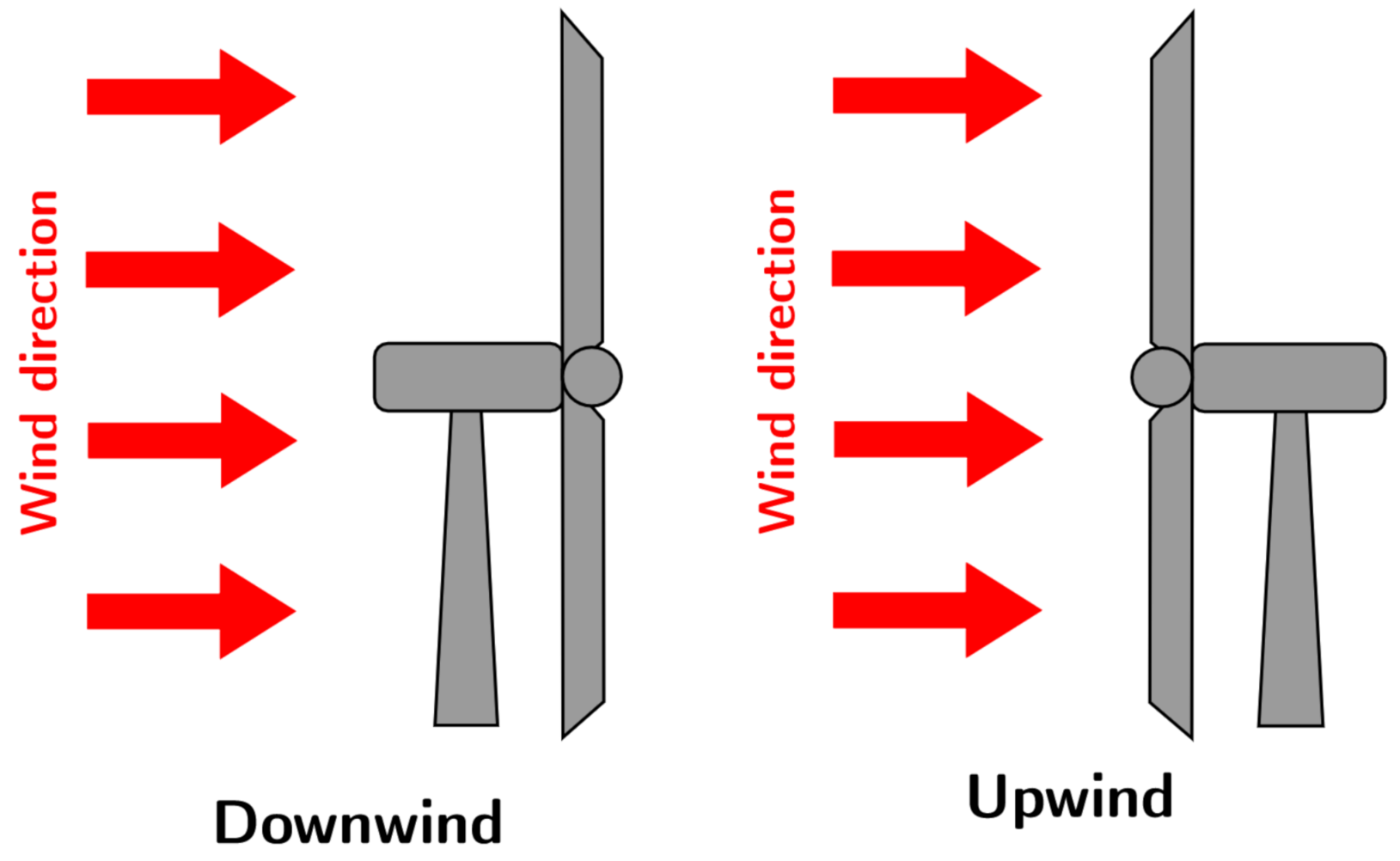
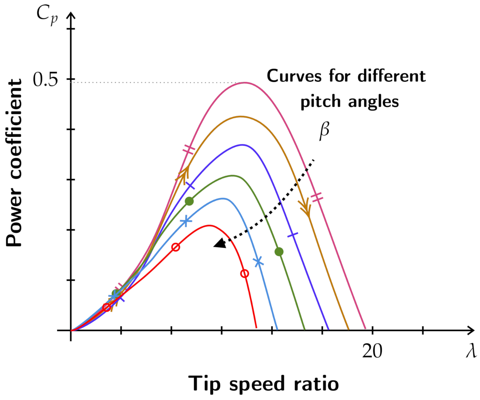
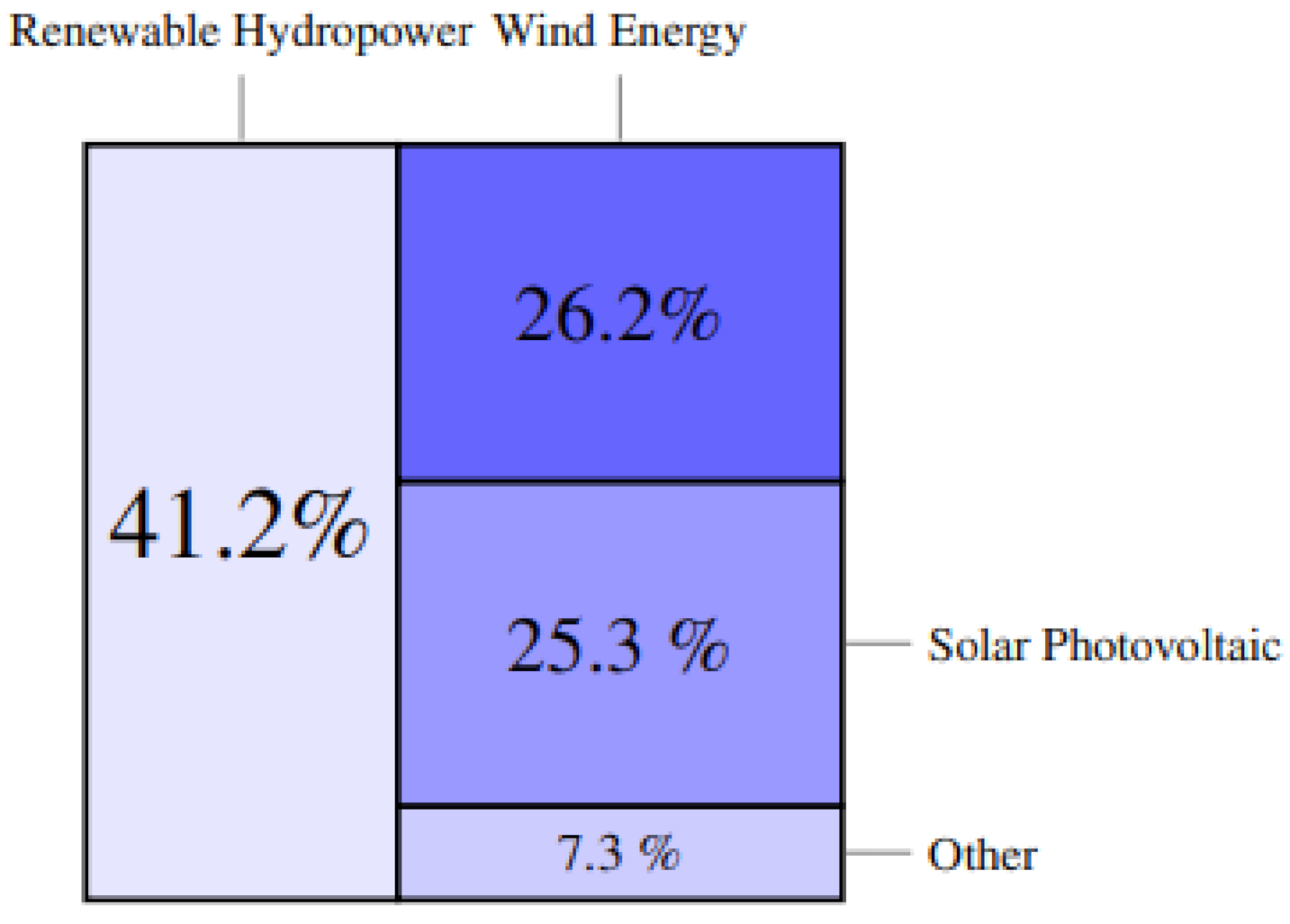
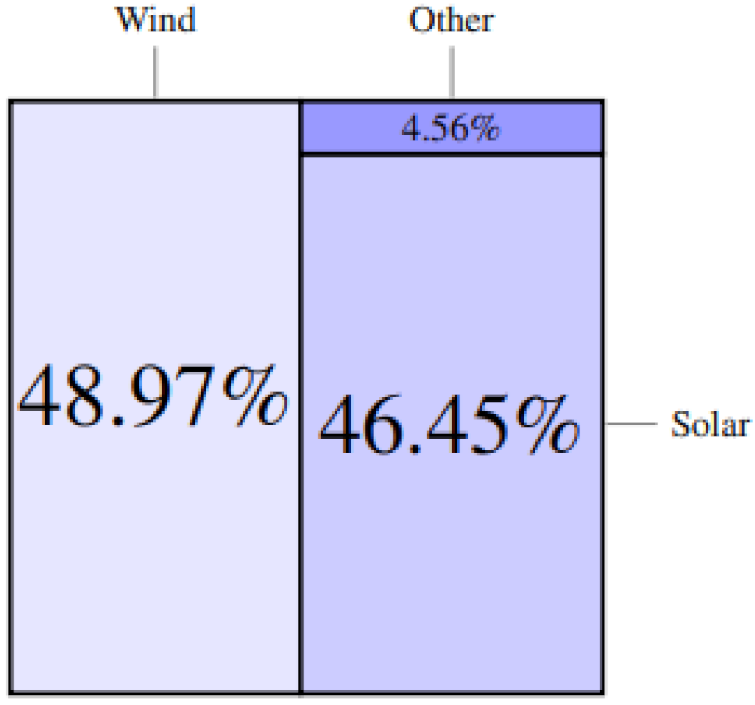
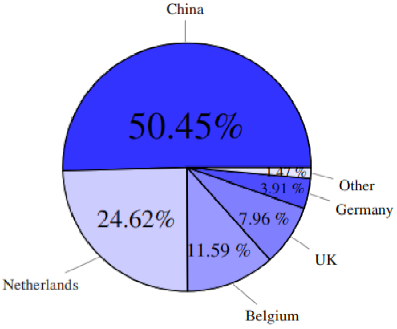
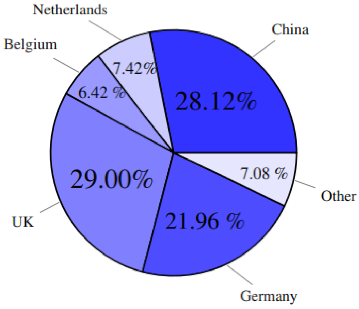
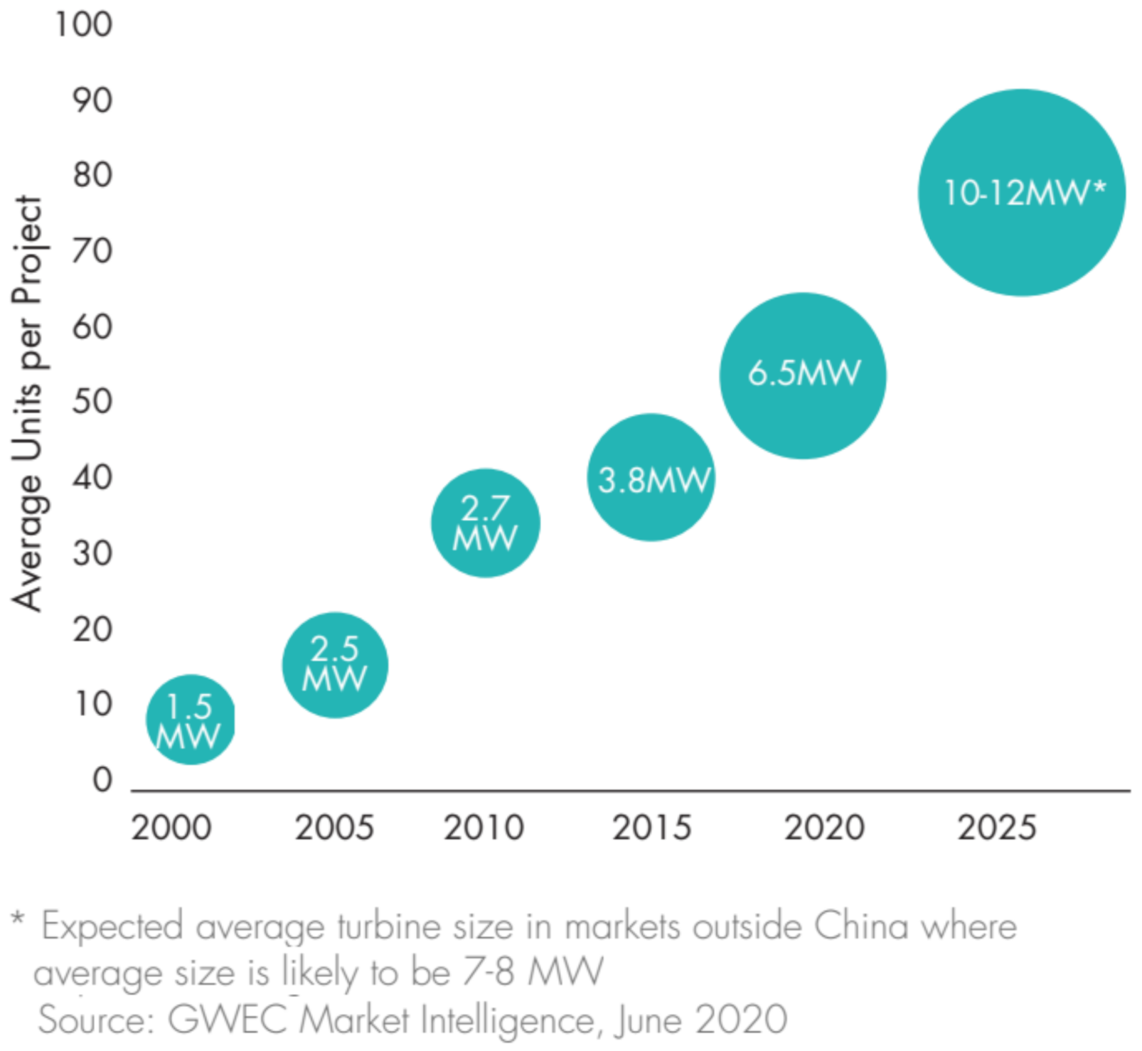
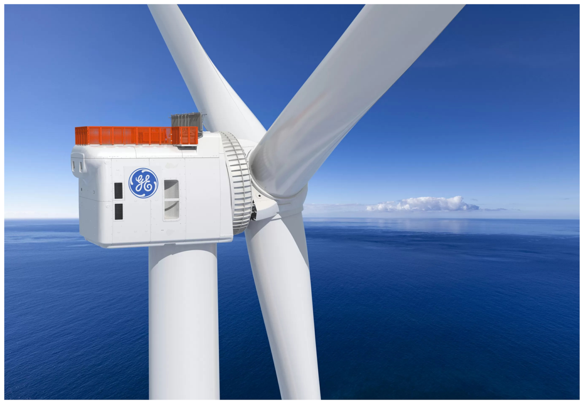
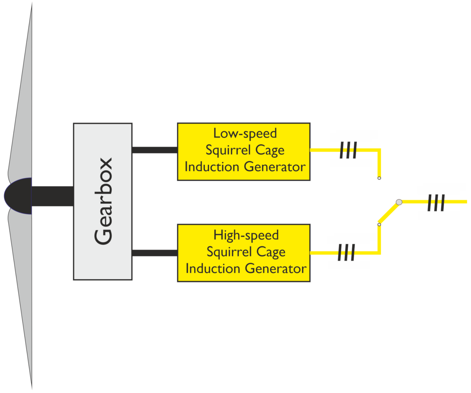
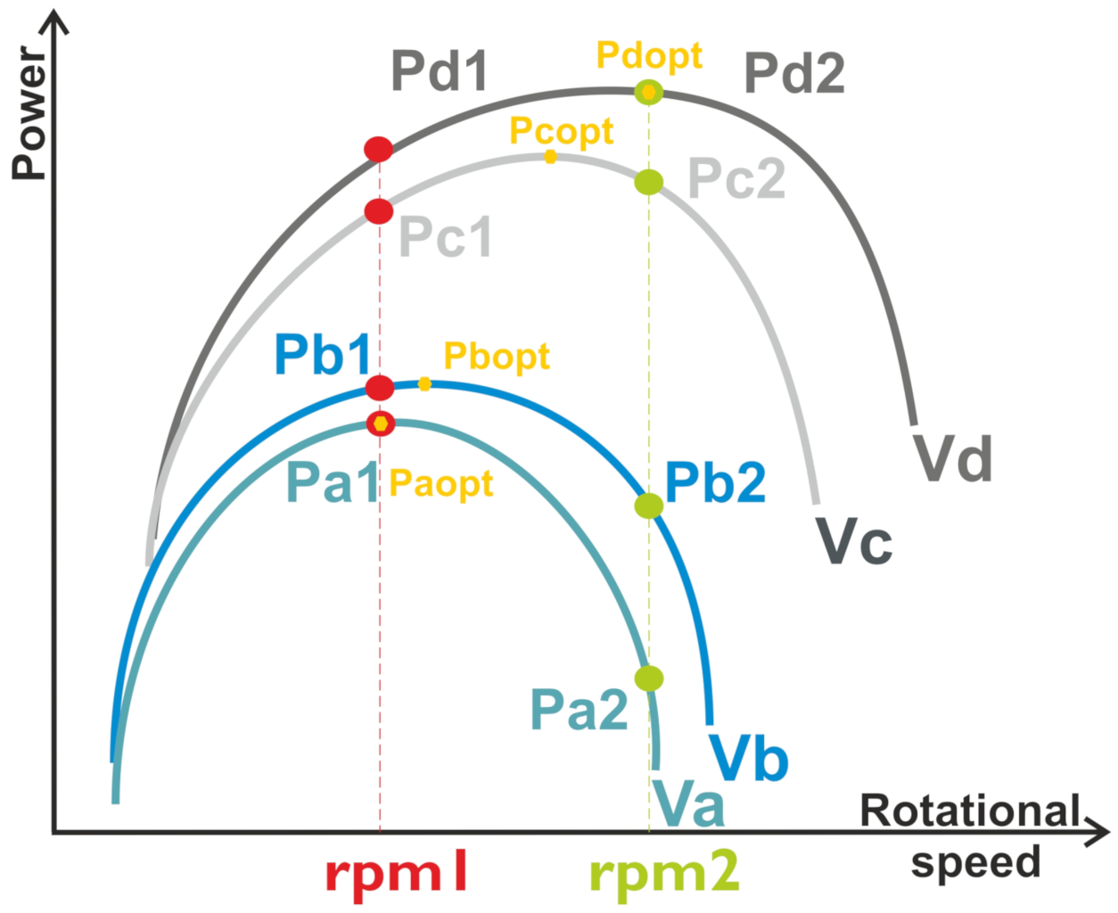
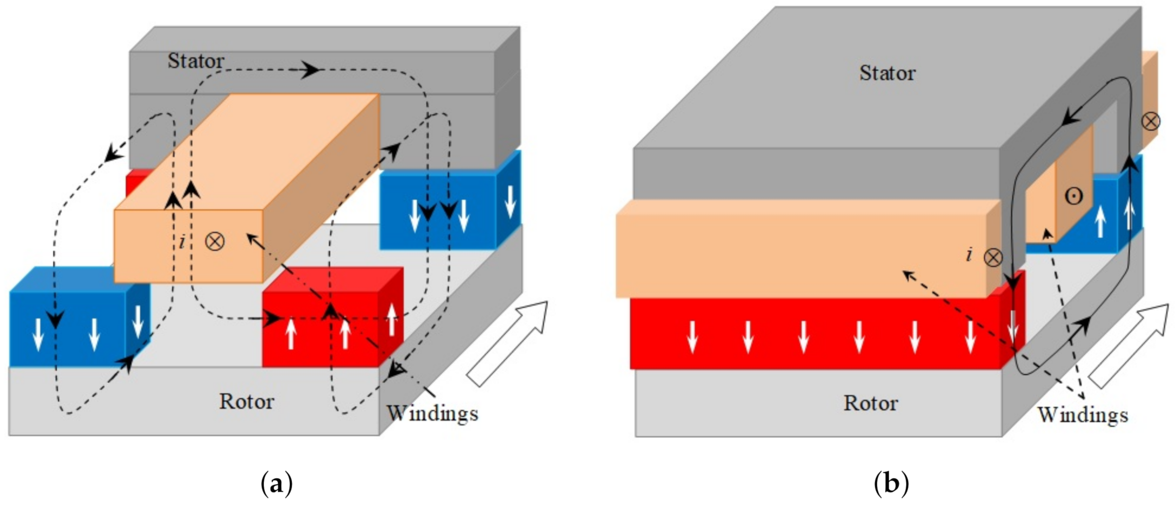
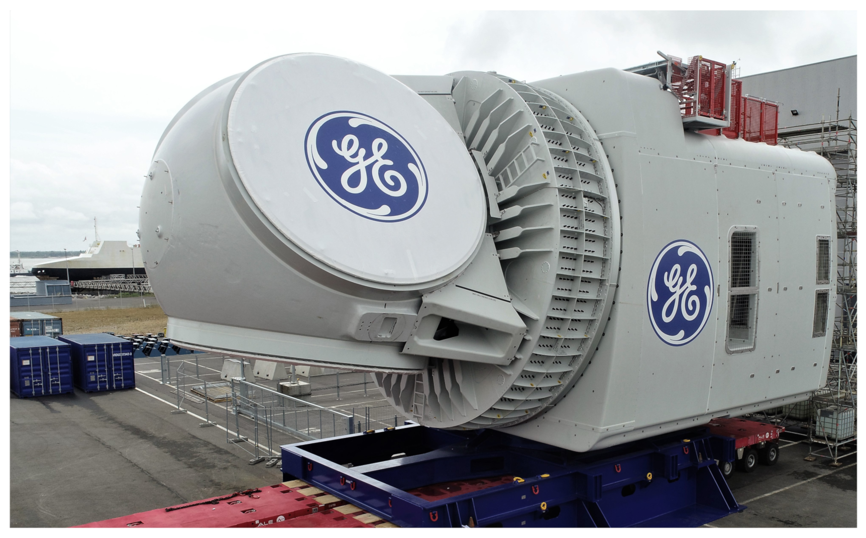
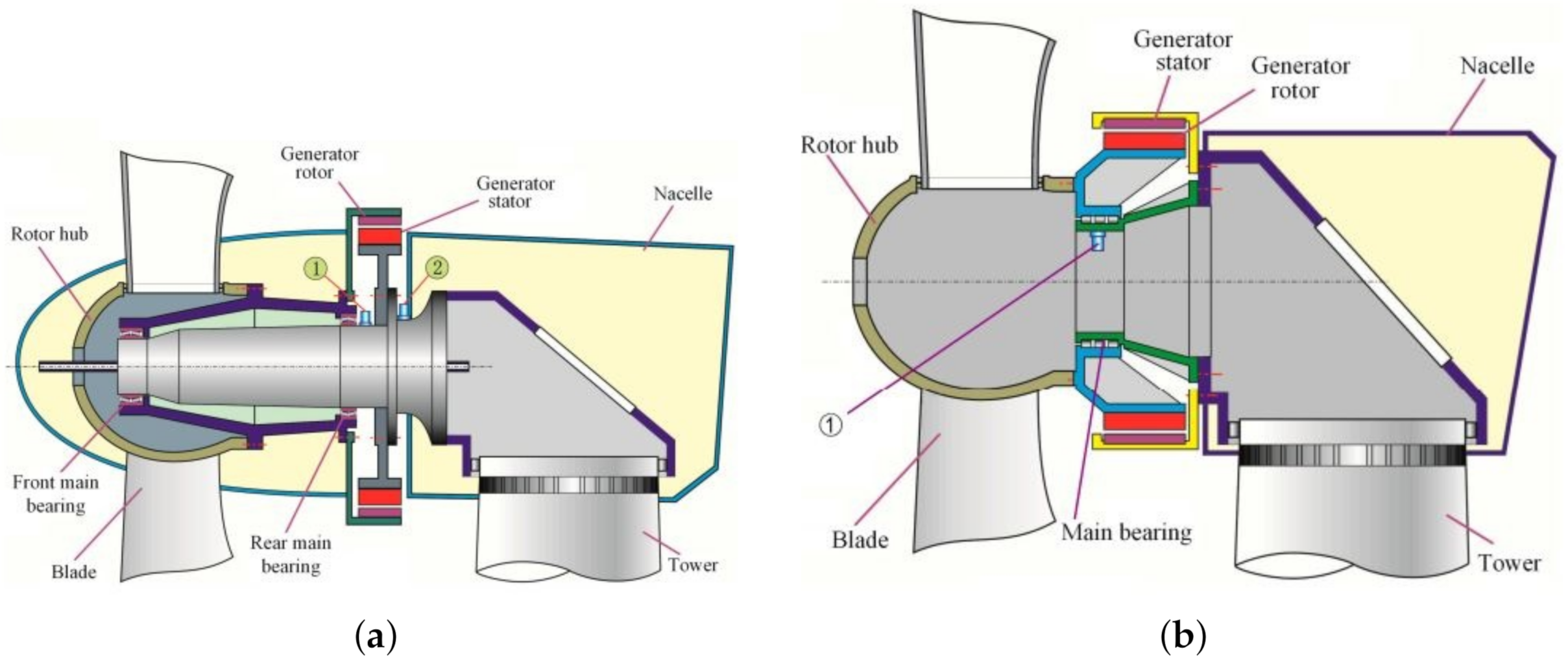
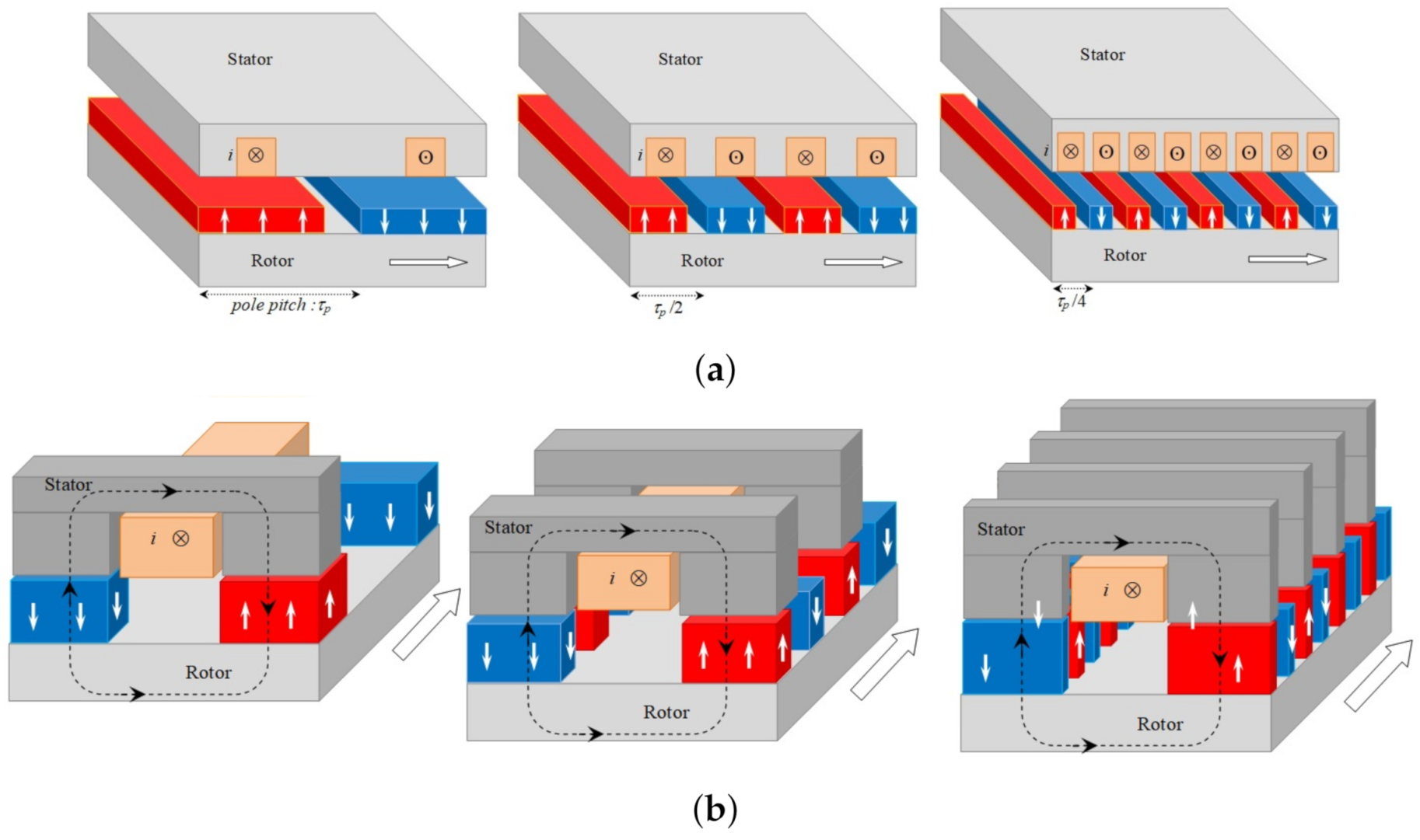
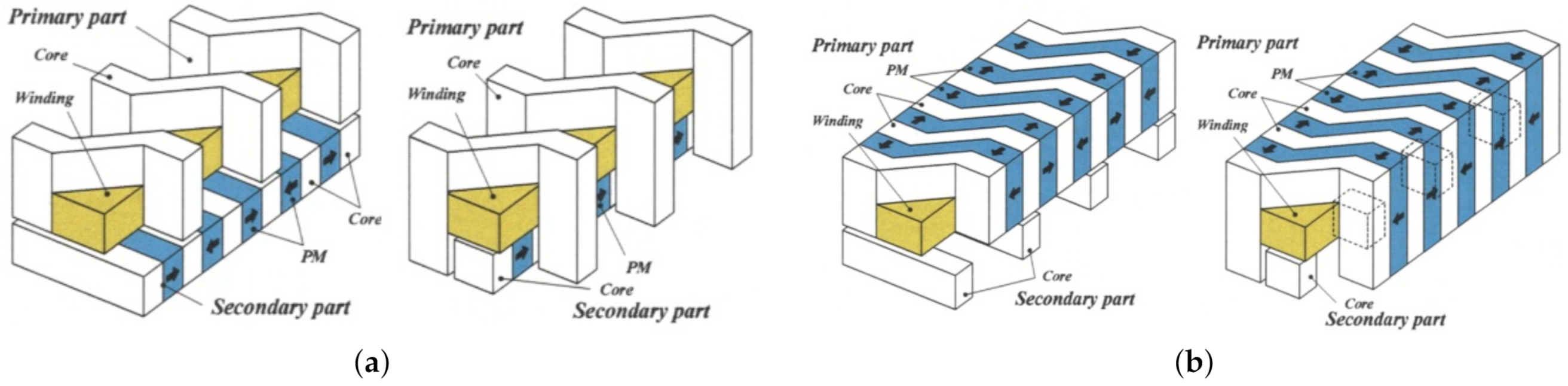
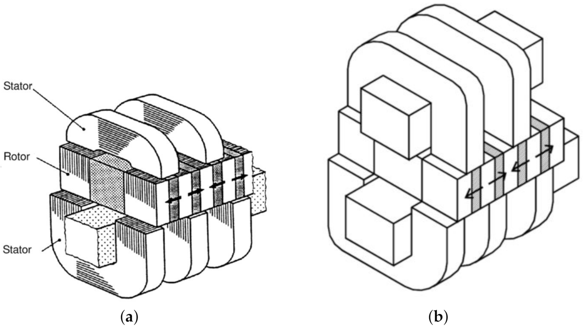
Table 1.
An example of a commercially available large wind turbine.
| Manufacturer | Wind Turbine | Power Rating (MW) | Wind Farms (Example) | ||
|---|---|---|---|---|---|
| Farms | Number of Turbines | Total Capacity (MW) | |||
| MHI-Vestas | V164-9.5 (offshore) | 9.5 | Northwester II (Belgium) [51] Kincardine II (United Kingdom) [52] Borssele 3&4 (Netherlands) [49] Borssele 5 (Netherlands) [49] | 23 5 76 2 | 219 48 722 19 |
| V164-8.4 (offshore) | 8.4 | Windfloat Atlantic (Portugal) [49] | 2 | 17 | |
| V150-5.6 (onshore) | 5.6 | Paskoonharju 2 (Finland) | 21 | 117.6 | |
| Siemens Gamesa | SG 8.0-167 DD (offshore) | 8 | Kaskasi II (Germany) [49] Le Tréport (France) [53] Noirmoutier (France) [54] Hornsea II (UK) [55] Borssele 1&2 (Netherlands) [49] | 38 62 62 165 94 | 342 496 496 1320 752 |
| SG 8.4-167 DD (offshore) | 8.4 | Seamade (Belgium) [49] Kriegers Flak (Denmark) [49] | 58 72 | 487 604 | |
| E-126 7.580 (onshore) | 7.5 | Estinnes (Belgium) [56] | 11 | 81 | |
| General Electric | Cypress 5.5-158 (onshore) | 5.5 | Oitis (Brazil) Metsälamminkangas (Finland) | 103 240 | 567 132 |
| NORDEX | N163/5.X | 5.X | Stakraft—Ventos de Santa Eugenia (Brazil) | 91 | 518.3 |
Table 2.
Example of multi-megawatt constant speed operational wind turbine.
| Wind Turbine | Power Control | Gearbox | Generator | |||
|---|---|---|---|---|---|---|
| Reference Manufacturer | Rated Power [MW] | Stages | Gear Ratio | Type | Voltage [V] | |
| V80-1.8 Vestas | 1.8 | OptiSlip | 3 | 1:112 | SQ | 690 |
| NM72/2000 NegMicon | 1.5–2 | Active-Stall | 3 | 1:84 | SQ | 690 |
| Bonus | 1–2.3 | Active-Stall | 3 | 1:98 | SQ | 690 |
| ECO 80/1670 Ecotècnia | 1–2 | Stall | 3 | 1:100 | SQ | 690 |
| N60/1300 Nordex | 1.3 | Stall | 3 | 1:94.4 | SQ | 690 |
Table 3.
Example of multi-megawatt variable speed with full scale frequency converter wind turbine concept (SCIG system with three-stage gearbox).
Table 3.
Example of multi-megawatt variable speed with full scale frequency converter wind turbine concept (SCIG system with three-stage gearbox).
| Wind Turbine | Gearbox | Generator | |||
|---|---|---|---|---|---|
| Reference/Manufacturer | Rated Power (MW) | Stages | Gear Ratio | Type | Voltage (V) |
| PS-1800 RRB Energy | 1.8 | 3 | 1:61 | SCIG | 690 |
| SWT-3.6-120 Siemens | 3.6 | 3 | 1:119 | SCIG | 690 |
| V 126-3.45 MW Vestas | 3.45 | 3 | 1:125.16 | SCIG | 750 |
Table 4.
Example of multi-megawatt variable speed with partial-scale frequency converter wind turbine concept.
Table 4.
Example of multi-megawatt variable speed with partial-scale frequency converter wind turbine concept.
| Wind Turbine | Gearbox | Generator | |||
|---|---|---|---|---|---|
| Reference Manufacturer | Rated Power (MW) | Stages | Gear Ratio | Type | Voltage (V) |
| N149/4.5 Nordex | 4.5 | 3 | 1:113.5 | DFIG | 660 |
| SG 5.0-145 Siemens | 5.0 | 3 | 1:128.7 | DFIG | 690 |
| SL 6000/155 Sinovel | 6 | 3 | DFIG | 6300 | |
| UP 6000/136 United Power | 6 | DFIG | 6600 | ||
| 6.2M-152 Repower | 6.2 | 3 | 1:116 | DFIG | 6600/660 |
Table 5.
The main characteristics of some permanent magnets.
| Remanence (T) [111] | Energy Product (Kj/m3) [111] | Maximal Temperature T (°C) [112] | Price [113] | |
|---|---|---|---|---|
| Ferrites | 0.20–0.46 | 6.4–41.8 | 300 | Cheap |
| SmCo | 0.87–1.19 | 143–251 | 250–350 | Medium |
| NdFeB | 1.08–1.49 | 220–430 | 150 | Expensive |
Table 6.
List of ultra-large operational direct drive permanent magnet synchronous generators.
| Wind Turbine | Rated Power (MW) | Manu- Facturer | Rotor Diameter (m) | Hub Height (m) | Electric Generator | Power Converter | |||||
|---|---|---|---|---|---|---|---|---|---|---|---|
| Manu- Facturer | Rated Power (MW) | Rated Speed (rpm) | Rated Ferquency (Hz) | Rated Current (A)/ Voltage (V) | Insulation Class | Rated Current (A)/ Rated Voltage (V) | |||||
| Haliade-X (Offshore) | 12 | GE Renewable Energy | 220 | 138 | GE | 12.79 | 7.81 | 7.81 | 2 × 1455/ 3220 | F | |
| SG 11.0-200 DD (Offshore) | 11 | Siemens Gamesa | 200 | 140 | Siemens Gamesa | 11–12 | 8.6– 9.1 | 14-15 | 2 × 4900–5000/ 820 | H | 6000/690 |
| SG 8.0-167 DD | 8 | Siemens Gamesa | 167 | 119 | Siemens Gamesa | 8.4–9.4 | 10.3– 10.8 | 12–13 | 2 × 4000/820 | F | 4250/690 |
| SWT-7.0-154 | 7 | Siemens Gamesa | 154 | 120 | Siemens Gamesa | 7–7.35 | 10.3– 10.8 | 12–13 | 1 × 3400/750 | F | 2 × 4000/690 |
| GW 171/6450 | 6.45 | Goldwind | 171 | 109 | Xingjiang Goldwind | 6.9 | 10.7– 12.84 | 10.7 | 1560/720 | F | 5941/690 |
Table 7.
Example of multi-megawatt variable speed with full-scale frequency converter wind turbine concept (PMSG/EESG system with one/two-stage gearbox).
Table 7.
Example of multi-megawatt variable speed with full-scale frequency converter wind turbine concept (PMSG/EESG system with one/two-stage gearbox).
| Wind Turbine | Gearbox | Generator | ||||
|---|---|---|---|---|---|---|
| Reference | Manufacturer | Rated Power [MW] | Stages | Gear Ratio | Type | Voltage [V] |
| M5000-116/135 | Areva | 5 | 1 | 1:10 | PMSG | 3300 |
| WWD-3 D120 | WinWinD | 3 | 2 | PMSG | 690 | |
| G128/5000 | Gamesa | 5 | 2 | 1:41 | PMSG | 690 |
| HTW5.2-136 | Hitachi | 5.2 | 2 | 1:40 (Approx.) | PMSG | 33,000 |
| AD 8-180 | Adwen | 8 | 2 | 1:41 | PMSG | 6600 |
| SCD 8.0MW | Aerodyn | 8 | 2 | 1:27 | EESG | - |
| MySE7.25-158 | Guangdong Mingyang | 7.25 | 2 | 1:23.18 | PMSG | 690 |
| V164-10MW | Vestas | 10 | 2 | 1:40.8 | PMSG | 730 |
Publisher’s Note: MDPI stays neutral with regard to jurisdictional claims in published maps and institutional affiliations. |
© 2022 by the authors. Licensee MDPI, Basel, Switzerland. This article is an open access article distributed under the terms and conditions of the Creative Commons Attribution (CC BY) license (https://creativecommons.org/licenses/by/4.0/).
Share and Cite
MDPI and ACS Style
Bensalah, A.; Barakat, G.; Amara, Y. Electrical Generators for Large Wind Turbine: Trends and Challenges. Energies 2022, 15, 6700. https://doi.org/10.3390/en15186700
AMA Style
Bensalah A, Barakat G, Amara Y. Electrical Generators for Large Wind Turbine: Trends and Challenges. Energies. 2022; 15(18):6700. https://doi.org/10.3390/en15186700
Chicago/Turabian StyleBensalah, Amina, Georges Barakat, and Yacine Amara. 2022. "Electrical Generators for Large Wind Turbine: Trends and Challenges" Energies 15, no. 18: 6700. https://doi.org/10.3390/en15186700
Note that from the first issue of 2016, this journal uses article numbers instead of page numbers. See further details here.