
A Novel Magnetic Circuit Design Method for a Permanent Magnetic Chuck of a Wall-Climbing Robot

1
School of Mechanical Engineering, Shanghai Jiao Tong University, Shanghai 200240, China
2
School of Logistics Engineering, Shanghai Maritime University, Shanghai 201306, China
3
School of Mechanical and Automotive Engineering, Shanghai University of Engineering Science, Shanghai 201620, China
*
Author to whom correspondence should be addressed.
Energies 2022, 15(18), 6653; https://doi.org/10.3390/en15186653
Submission received: 30 July 2022
/
Revised: 2 September 2022
/
Accepted: 6 September 2022
/
Published: 12 September 2022
(This article belongs to the Special Issue Advances in Energy Optimal Control of Electromechanical and Robotic Systems)
Abstract
:Permanent magnet wall-climbing robots are widely used in the maintenance of tanks in the petrochemical industry and the overhaul of large-pressure pipelines in the hydropower industry. One of the difficulties is to achieve the safe and reliable adsorption of wall-climbing robots. Based on the Halbach array, a double-layer superposition magnetic circuit magnetization method is designed in this paper. Under the same constraints, the adsorption force of the permanent magnetic chuck is increased by at least compared with the traditional magnetic circuit design method. Under the working air gap of 1∼9 mm, the average magnetic energy utilization rate is increased by at least . This approach not only improves the magnetic energy utilization of the permanent magnetic chuck but also improves the adsorption safety of the wall-climbing robot.
1. Introduction
In recent years, due to the development of the wall-climbing robot technology, manual work can be replaced in some dangerous scenarios, such as the detection and maintenance of petrochemical tanks, rust removal and painting in the shipbuilding industry. Therefore, wall-climbing robots have attracted the attention of many research institutions and researchers at local and international levels [1,2,3,4,5]. According to the adsorption method, the types of wall-climbing robots are mainly divided into negative pressure adsorption [3], permanent magnet adsorption [5], electromagnetic adsorption [6] and bionic adsorption [1]. According to the movement mode, wall-climbing robots are mainly divided into wheel [7], crawler [8], wheel foot [4] and leg-type robots [3]. At present, the main research focus for developing wall-climbing robots that are suitable for working on metal walls is on wheeled or crawler-type permanent magnet adsorption wall-climbing robots [6,8,9,10,11,12]. Wheeled and tracked permanent magnet adsorption wall-climbing robots are favored by many industries because of their reliable adsorption and flexible movement. Researchers have also performed extensive experiments on permanent magnet adsorption wall-climbing robots to achieve reliable adsorption and flexible movement [7,8,13,14,15]. Ultimately, the contradiction between the reliable adsorption and flexible movement of wall climbing robots is attributed to the design of the permanent magnet adsorption mechanism [16,17,18,19,20,21].
At present, the permanent magnet adsorption mechanism for the wheeled wall-climbing robot is mainly divided into two types: one is a magnetic wheel and the other is a magnetic chuck. For the magnetic wheel design, Seung Chul Han et al. [22] proposed a method to adjust the magnetic adsorption force by adding a magnetic guide needle in the design of the magnetic wheel. Yihui Zhang et al. [23] proposed a method to adjust the magnetic wheel adsorption force by changing the diameter of the permanent magnet. This method can improve the magnetic adsorption force when the size of the magnetic wheel is determined, but it will be affected by the thickness of the yoke between the magnets in the magnetic wheel. W. Fischer et al. [24] designed a permanent magnet wheeled robot for detecting ultrathin fragile walls. Every magnetic wheel consists of ten magnetic rings. During the working process, the contact and separation of the magnetic wheel are controlled by the lifting mechanism to achieve control of the magnetic adsorption force. Myounggyu Noh et al. [25] modeled and analyzed the adsorption force between the magnetic wheel and the metal wall. By estimating the magnetic resistance between the magnetic wheel and the contact wall, the calculation model of the magnetic attraction force is derived. Zhengyi Xu et al. [26] designed an optimized magnetic wheel solution for sandblasting and descaling wall-climbing robots, which achieves flexible motion on large-curvature surfaces. Most of the aforementioned permanent magnet adsorption wall-climbing robots based on the magnetic wheel design are only suitable when small load capacities are required.
Another suitable design for the permanent magnet adsorption wall-climbing robot is the magnetic chuck. Magnetic chuck wall-climbing robots are mainly used when high load capacities are required. Regarding the optimal design of magnetic circuits for permanent magnetic chucks, Minghui Wu et al. [27], Wei Song et al. [28] and Jiashe Zhu et al. [29] conducted an in-depth study on the magnetic circuit optimization design of the magnetic chuck using the opposite magnetization method. They analyzed the effects of the arrangement between the magnetic poles, the thickness of the yoke and the size of the magnetic poles on the adsorption force. W. Shen et al. [30] deduced the design requirements for the adsorption force to prevent overturning of the wall-climbing robot. By analyzing the statics of the wall-climbing robot under different working conditions, they designed two different types of permanent magnetic chucks. Chenfei Yan et al. [31] proposed a magnetic chuck composed of multidirectional magnetized permanent magnets. Compared with the magnetic chuck composed of the Halbach array magnetization, the utilization rate of permanent magnets is higher. Guangdou Liu et al. [32] proposed a new one-dimensional Halbach array using curved permanent magnets. Jiangbo Wang et al. [33] proposed an optimized linear Halbach array magnetic circuit design method. By optimizing the size parameters of the magnetic poles, the utilization of the magnetic energy of the Halbach array is improved. Min seob Sim et al. [34] proposed mathematical modeling and analysis methods for open-space Halbach arrays, namely, the ampere model and the Biot Savart law (AB method). The proposed AB method quickly and accurately analyzes the Halbach array with minimum memory consumption. Jaewook Lee et al. [35] proposed a topology optimization method to design patterns of permanent magnets in a Halbach array using the isoparametric projection method.
In summary, some research has been conducted on the optimization of the design of magnetic circuit for the permanent magnet adsorption wall-climbing robot. However, researchers have not systematically studied the effects of different magnetic circuit optimization design methods on the adsorption force for a fixed-size permanent magnet adsorption mechanism. Moreover, the structural parameters of the magnetic pole, the thickness of the yoke and the working air gap are equally important for the design of the permanent magnet adsorption mechanism, which must be considered in the design. Therefore, based on a fixed-size permanent magnetic chuck, the effects of different magnetization methods on the adsorption force of the magnetic chuck are simulated and analyzed in this paper. Moreover, we analyzed the effects of the magnetic pole size parameters, yoke thickness and working air gap on the adsorption force. Regarding the magnetic chuck, an optimal design method of a double-layer superimposed Halbach array is proposed. A new parameter index is defined to evaluate the magnetic energy utilization rate of the adsorption mechanism.
The overall arrangement of this paper is as follows. In Section 1, the research status of the adsorption mechanism for wall-climbing robots is summarized. In the Section 2, the static analysis of the permanent magnet adsorption wall-climbing robot under different working states is implemented, and then, based on the results, a double-layer superposition Halbach array magnetic circuit optimization design method for the magnetic chuck is proposed. In the Section 3, the effects of different magnetization methods, magnetic pole size parameters and yoke thicknesses on the adsorption force of the magnetic chuck are analyzed. The accuracy of the simulation results is verified by tensile testing of the actual magnetic chuck. The experimental results are presented in the Section 4. In the Section 5, several conclusions drawn from this research are presented.
2. Methods
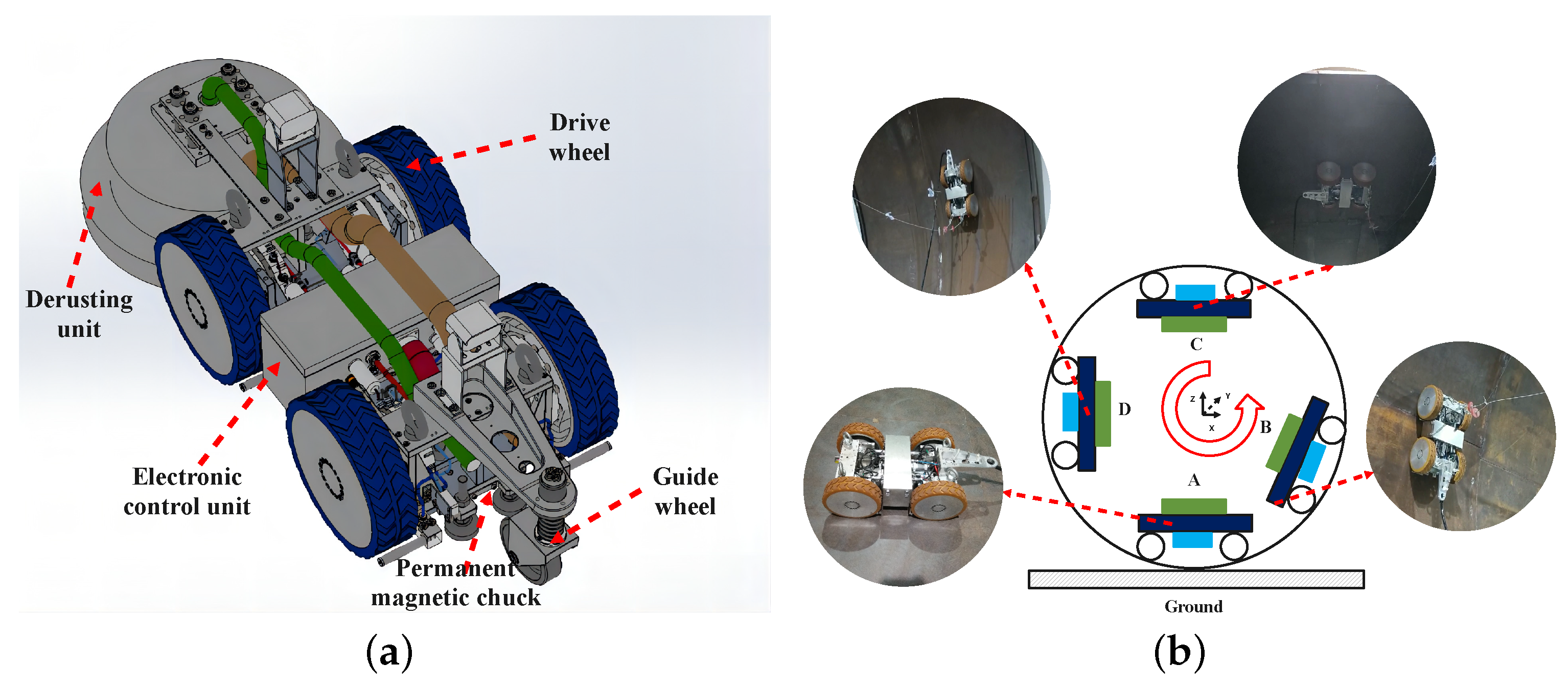
In this paper, the application of a noncontact permanent magnet wall-climbing robot in the inspection and maintenance tasks of water diversion penstocks is used as an example. The fundamental composition of the wall-climbing robot and the typical state in the working process are shown in Figure 1a. The wall-climbing robot is mainly composed of a derusting unit, four driving wheels, an auxiliary guide wheel, an electronic control unit and three permanent magnetic chucks.
When the wall-climbing robot works inside the penstock, the typical working state is divided into four working conditions A, B, C and D, as shown in Figure 1b. In State A, the wall-climbing robot is in a static equilibrium state. In State B, the wall-climbing robot may slide down or overturn due to the effect of gravity. In State C, the wall-climbing robot may disengage along the normal direction under the influence of gravity. In State D, if the support force of the wall for the wall-climbing robot is not sufficiently strong, rollover may occur. A detailed static analysis of the four working states of the wall-climbing robot is provided below.
2.1. Static Analysis of Wall-Climbing Robots under Different Working Conditions
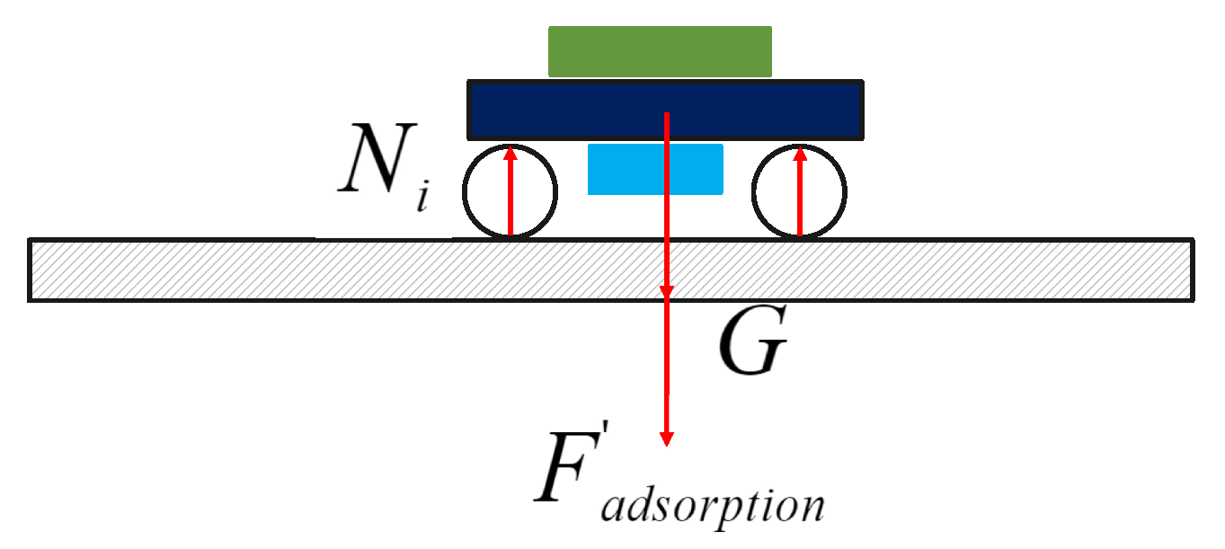
The static analysis of the wall-climbing robot in State A can be simplified as shown in Figure 2. In this state, the wall-climbing robot will not have any accidents.
where represents the support force on each wheel, G represents the weight of the whole robot and represents the required adsorption force.
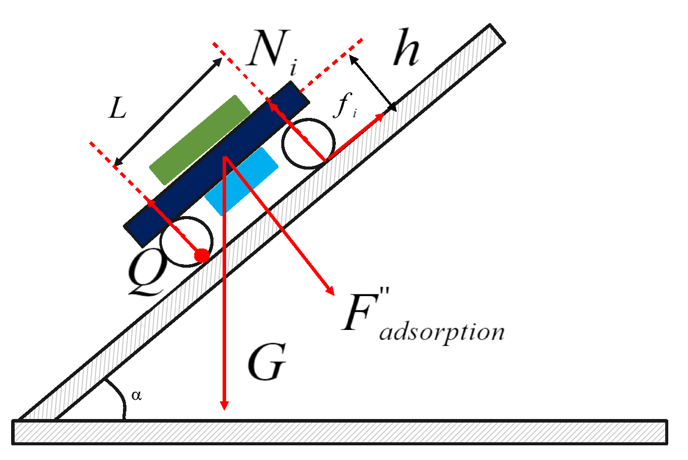
The force analysis of the wall-climbing robot in State B can be simplified as shown in Figure 3. In this state, the possible accidents of the wall-climbing robot that occur are sliding down and rolling over. The required adsorption force must satisfy the following equation to prevent these accidents:
where represents the support force on each wheel, G represents the weight of the whole robot, represents the required adsorption force, represents the angle between the robot and the horizontal plane, represents the friction force on each wheel and represents the resulting force of friction.
The critical condition for rollover along the Q point is that the supporting force of the two front wheels is zero. The following moment inequalities Equation (4) must be satisfied to avoid these accidents:
where L represents the track width between the front and rear wheels, and h represents the distance from the center of gravity of the robot body to the adsorption plane.
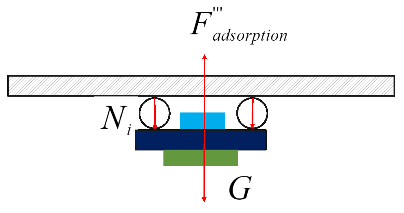
In State C, the force analysis of the wall-climbing robot can be simplified as shown in Figure 4. The most likely accident in this state is that the robot disengages along the normal direction. The adsorption force must satisfy the following conditions to avoid this accident:
where represents the support force on each wheel, G represents the weight of the whole robot and represents the required adsorption force.
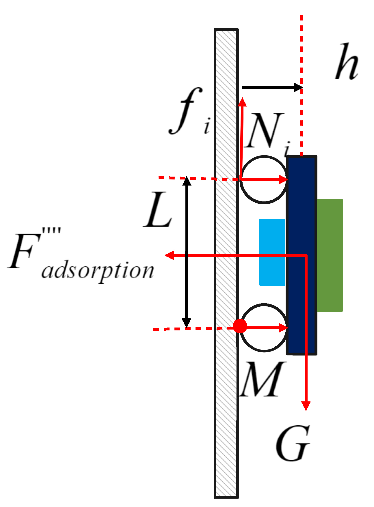
In State D, the analysis of the force of the wall-climbing robot can be simplified, as shown in Figure 5. In this state, the robot is most likely to roll over. The adsorption force must satisfy the following conditions to avoid this accident:
where represents the support force on each wheel, G represents the weight of the whole robot, represents the required adsorption force and represents the friction force on each wheel.
The adsorption force must satisfy the following moment inequality to ensure that the wall-climbing robot does not overturn longitudinally from Point M in Equation (8).
where L represents the track width between the front and rear wheels, and h represents the distance from the center of gravity of the robot to the adsorption plane.
Based on the results of the static analysis conducted under all the aforementioned working conditions, we concluded that the adsorption force provided by the magnetic chuck must meet the following conditions to achieve the reliable operation of the wall-climbing robot in the penstock:
where represents the minimum adsorption force required for reliable adsorption. After considering the safety factor, the minimum adsorption force is obtained from (Equation 10).
Based on the analysis described above, the magnetic circuit of the adsorption mechanism must be optimized to meet the requirements for reliable adsorption and flexible movement. When designing the permanent magnet adsorption mechanism, the self-weight of the robot body and load capacity must be considered. In this paper, the self-weight of the robot and load are 1100 N, the wheelbase is 460 mm and the height from the robot gravity center to the adsorption surface is 120 mm. Therefore, the minimum adsorption force that must be provided is 1148 N to achieve the reliable operation of the robot.
2.2. Modeling and Analysis of the Double-Layer Superimposed Halbach Array
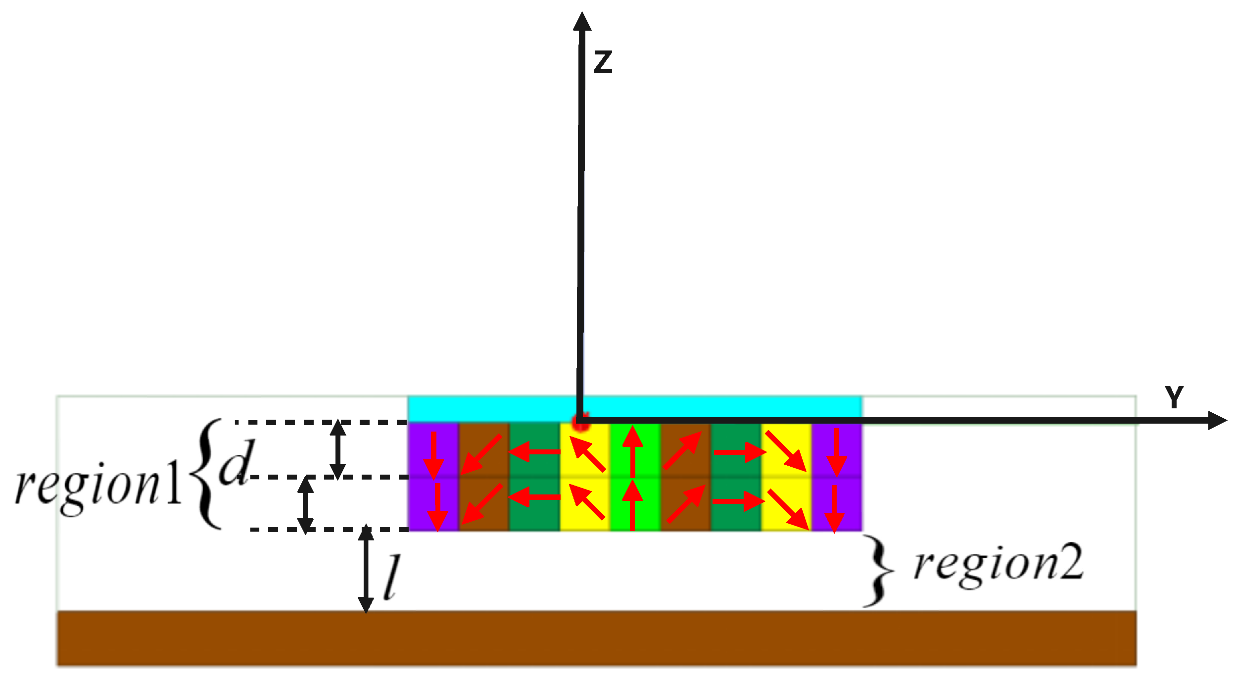
From the static analysis described above, the magnetic circuit must be optimized to improve the adsorption force and to ensure the reliable adsorption of the wall-climbing robot. According to the basic principle of magnetic circuit design, magnetic flux leakage is inevitable, and the magnetic field lines are continuous on any closed surface. Halbach array theory shows that Halbach arrays exert a “self-shielding effect” [36,37]. Permanent magnetic units with different magnetization directions are arranged in a certain order to form a Halbach array. The magnetic field has an obvious characteristic of being strong on one side and weak on the other. Based on the basic principle of magnetic circuit design and the theory of the Halbach array, as shown in Figure 6, an optimal method for designing the magnetic circuit of a two-layer superimposed Halbach array is proposed in this paper.
Maxwell’s equations [38] are the basis for the study of electromagnetic fields. The adsorption force of a permanent magnetic chuck on a metal wall can be obtained using Maxwell’s stress tensor method. The principle is simply described as follows: in isotropic and uniform media, the area fraction of the stress tensor T on curved surface S is equal to the adsorption force F generated by the permanent magnetic chuck.
where S is a closed surface in isotropic and uniform media, n is the unit vector of the external normal of the micro element , B is the magnetic flux density and is the relative permeability.
The magnetization vector of the ideal linear Halbach magnet changes smoothly and continuously according to the sinusoidal curve. Thus, the field strength on one side of the strong magnetic field of the magnet changes according to the sinusoidal law, and the field strength on the other side is zero. However, in practice, the ideal Halbach magnet does not exist, and it only approximately simulates the magnetic circuit of the Halbach magnet. The following assumptions are needed to establish the mathematical model of the magnetic field for the Halbach magnet:
- (1)
- The length of a nonideal Halbach array composed of segmented permanent magnets bonded together is unlimited, and the end effect of the Halbach array is not considered.
- (2)
- The demagnetization curve of a permanent magnet is linear, and its permeability is the same as that of air. The return permeability is .
- (3)
- The study area is an ideal space without free current.
- (4)
- The permeability of soft magnetic materials is infinite.
- (5)
- The magnetic energy loss on the yoke is not considered.
Based on the assumptions listed above, we presumed that the Halbach array consisting of segmented permanent magnets is magnetized by the superposition of the following two orthogonal sinusoids:
where m is the wavenumber, is related to , , is the remanence of the permanent magnet, is the permeability, represents the initial magnetization and , and represent the magnetizations in the X, Y and Z directions, respectively.
The following equation is obtained from Maxwell’s equation [38]:
where and represent the scalar magnetic potential of Region 1 and Region 2, respectively. Using , we obtain the value when :
where and represent the magnetic field strengths of Region 1 and Region 2, respectively. and represent the unit direction vector on each coordinate axis.
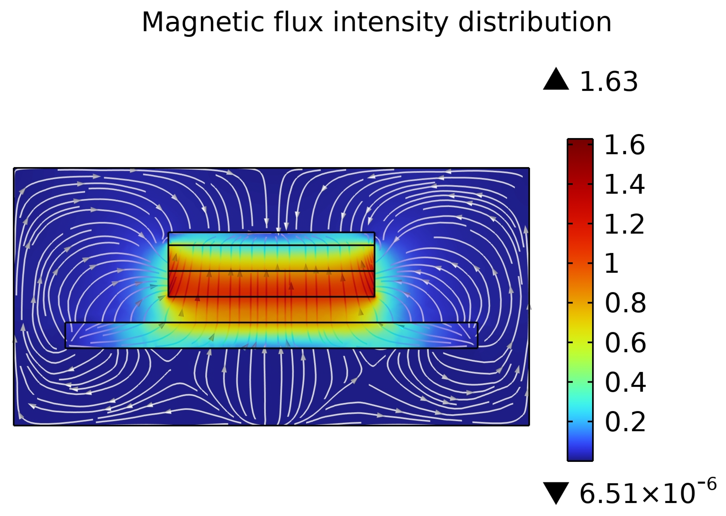
The magnetic lines and magnetic flux density distribution of the ideal Halbach array are shown in Figure 7. From the perspective of energy conservation, the external effective magnetic field of the ideal Halbach permanent magnet array is mainly concentrated under the permanent magnet array. The Halbach permanent magnet array leakage flux is relatively small, and the magnetic energy utilization rate is significantly improved.
3. Results
In this paper, according to the actual parameters of the climbing robot and the demand for the adsorption force, three permanent magnetic chucks with a size of mm are designed. The Ansoft Maxwell electromagnetic simulation software is used for the simulation analysis to assess the effects of different magnetization methods on the adsorption force of the permanent magnetic chuck. Second, the relationship between the adsorption force with the working air gap and the thickness of the yoke is discussed, when different magnetization methods are analyzed. Third, for the double-layer superposition Halbach array magnetic circuit design method, the effect of the size parameters of the magnetic pole on the adsorption force is analyzed. Finally, the accuracy of the simulation results is verified by analyzing the actual permanent magnetic chuck.
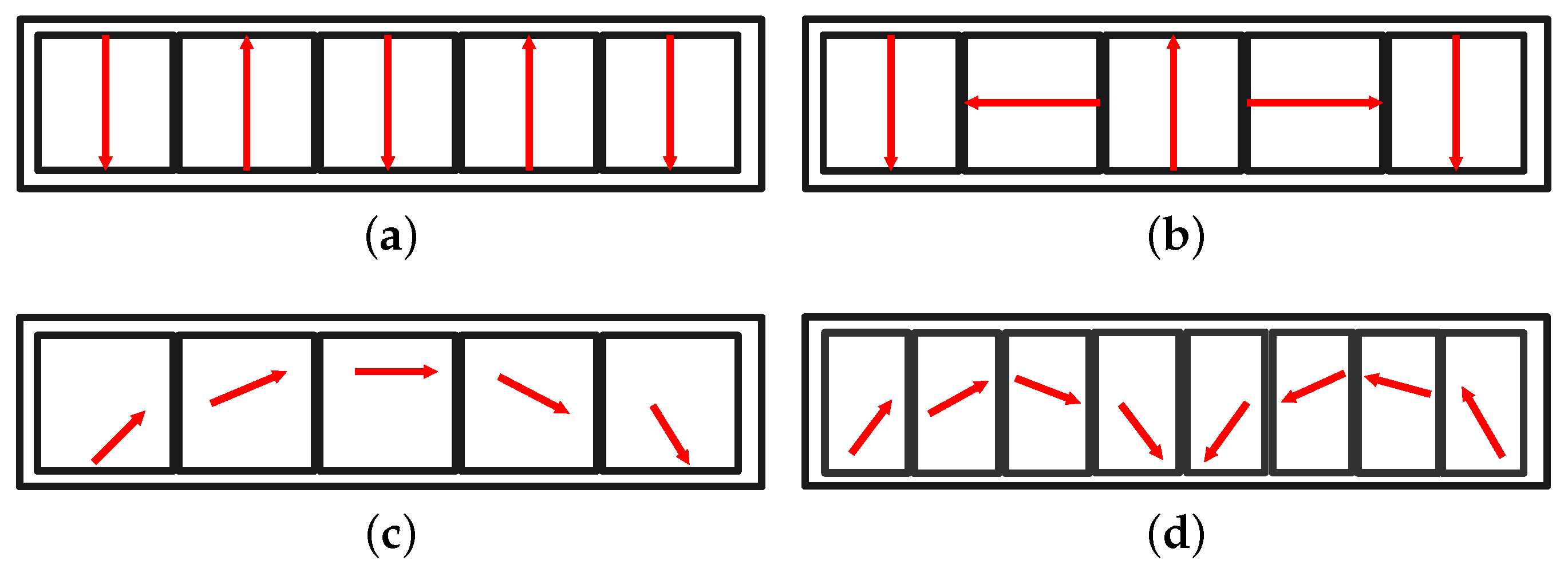
At present, the mainstream magnetization method of the permanent magnetic chuck is shown in Figure 8. The formula used to calculate the magnetic adsorption force of a permanent magnetic chuck with a three-dimensional finite element analysis is Equation (15) [39,40].
where is the area of a single grid and is the magnetic flux intensity of each grid element.
The permanent magnetic material used in this simulation is NdFeB-N35, the yoke material is industrial pure iron and the test steel plate material is Q235. The detailed parameters of the permanent magnetic materials are shown in Table 1.
The detailed settings of the permanent magnetic chuck simulating different magnetization methods are as follows:
- (1)
- Opposite magnetization. The permanent magnetic chuck is composed of five magnetic poles, of which two magnetic poles with a size of mm are arranged at the edge, and the remaining three magnetic poles with a size of mm are arranged in the middle. The magnetization direction between adjacent magnetic poles is opposite. The magnetic pole is magnetized according to the magnetization method shown in Figure 8a.
- (2)
- Halbach array magnetization. The permanent magnetic chuck is composed of five magnetic poles with a size of mm. The magnetic pole is magnetized according to the magnetization method shown in Figure 8b.
- (3)
- Sinusoidal magnetization. The permanent magnetic chuck is composed of 18 magnetic poles with a size of mm. The magnetic pole is magnetized according to the magnetization method shown in Figure 8c. The included angle of the magnetization direction between adjacent magnetic poles is .
- (4)
- Multidirectional magnetization (PMAD). The permanent magnetic chuck is composed of eight magnetic poles with a size of mm. The magnetization direction of the magnetic poles adopts a symmetrical form. The magnetic poles are magnetized in the directions of , , , , , , and according to Yan [31].
- (5)
- Double-layer superimposed Halbach array magnetization. The permanent magnetic chuck is composed of 18 magnetic poles, and the size of a single magnetic pole is mm. The magnetic poles are magnetized according to the magnetization method shown in Figure 6.
The adsorption force generated by the permanent magnetic chuck under different working air gaps and different yoke thicknesses is simulated and analyzed. Then, for the double-layer superimposed Halbach array, we simulate and analyze the effect of the size parameters of the magnetic pole on the adsorption force of the permanent magnetic chuck and optimize the existing indicators for evaluating the magnetic energy utilization of the permanent magnetic chuck according to the simulation results. Finally, we verify the accuracy of the simulation results by using the actual permanent magnetic chuck for tensile testing.
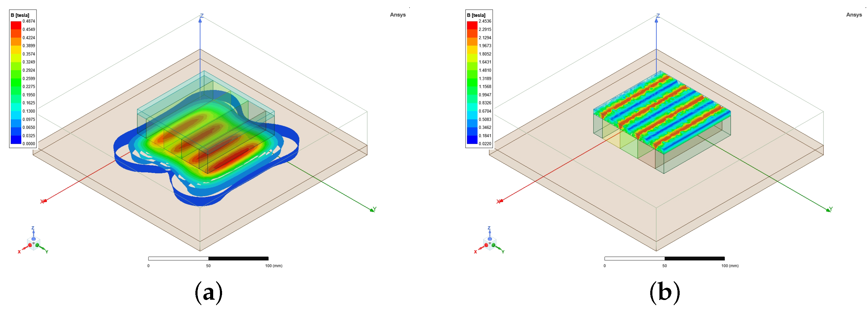
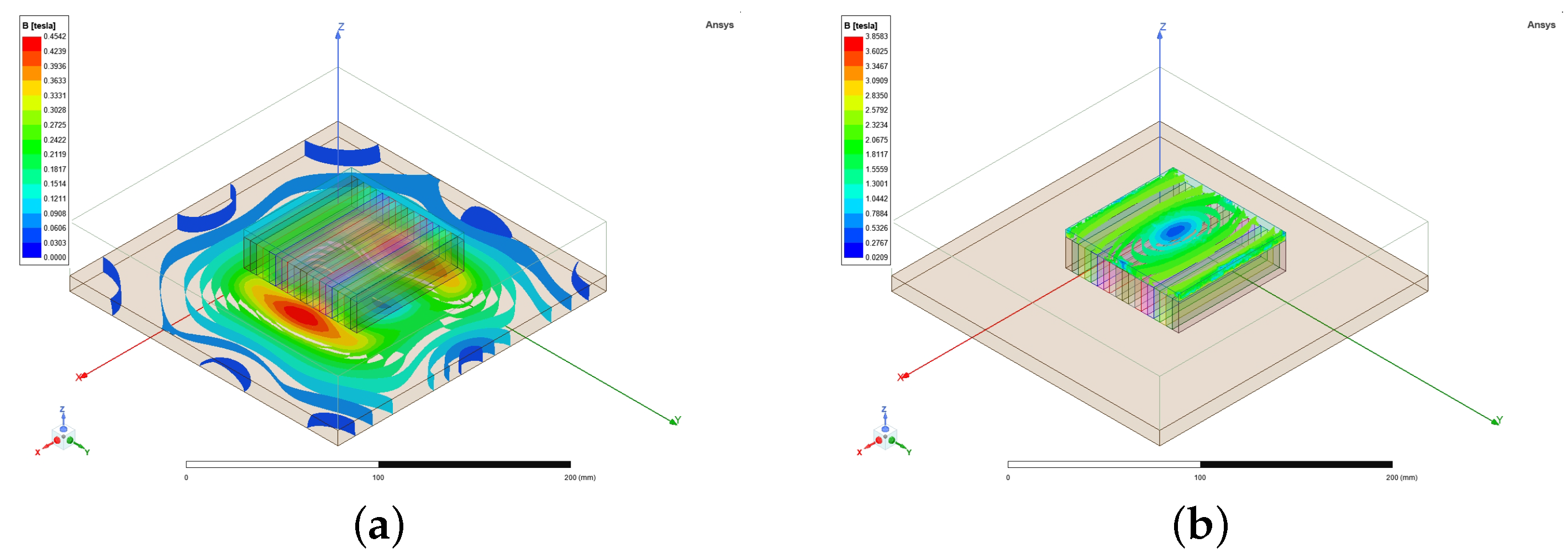
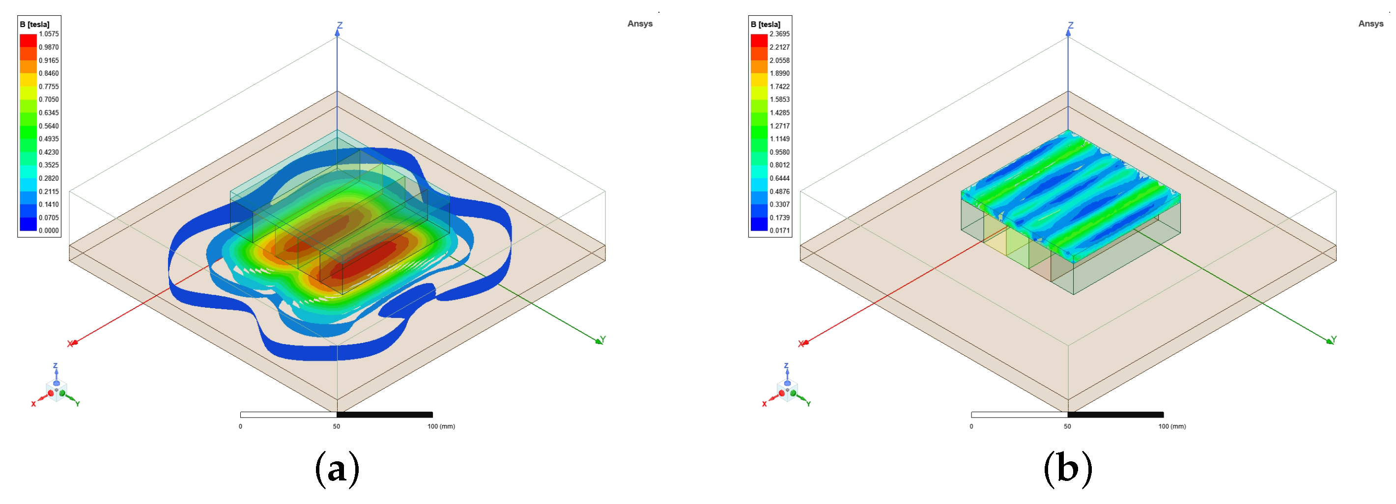
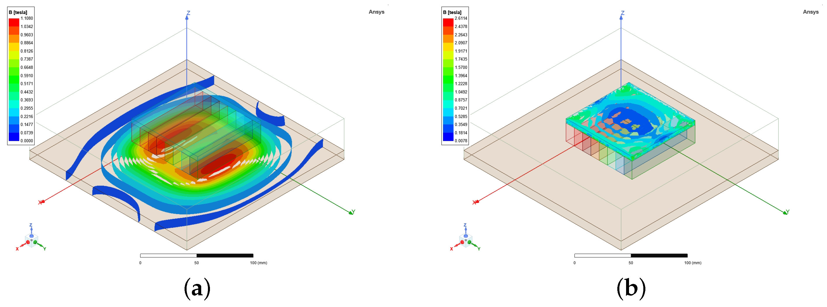
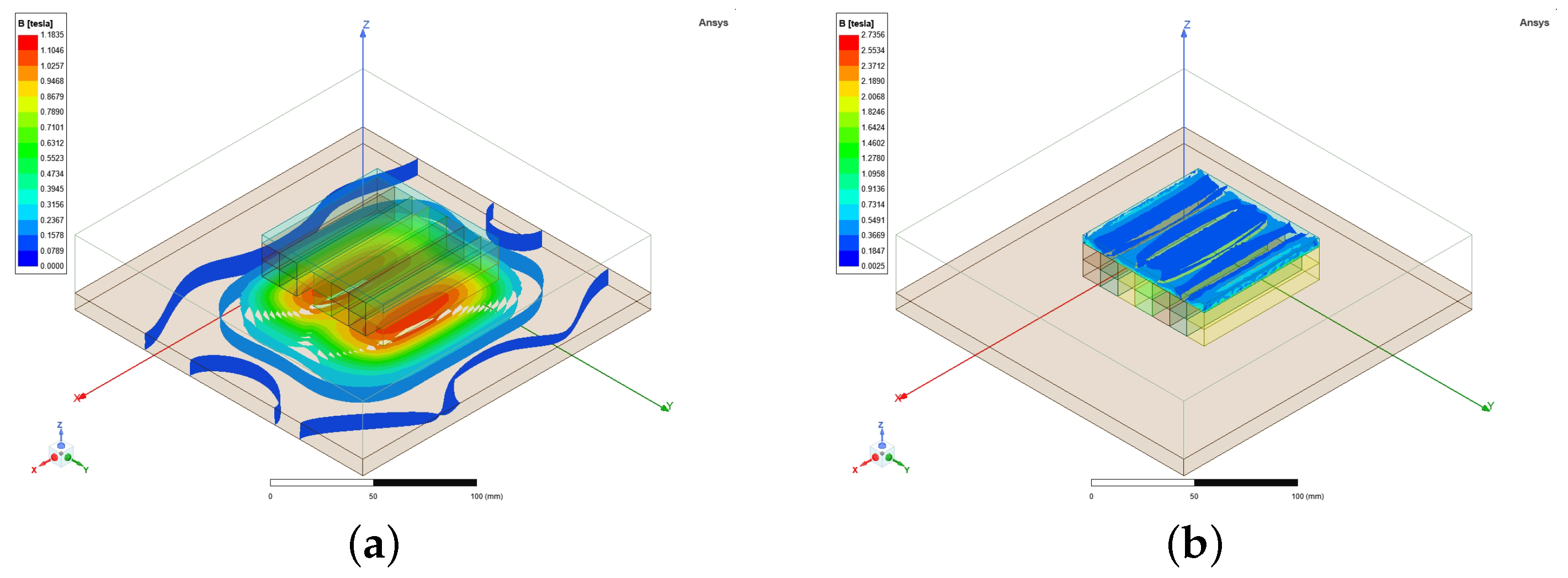
The distribution of the magnetic flux density on the test steel plate and yoke when different magnetization methods are adopted for the permanent magnetic chuck are shown in Figure 9, Figure 10, Figure 11, Figure 12 and Figure 13, respectively. As shown in the figure, when the double-layer superposition Halbach array magnetization method is adopted for the permanent magnetic chuck, the magnetic flux density on the yoke side is smaller. This result is closer to the magnetic flux density distribution of the ideal Halbach array.
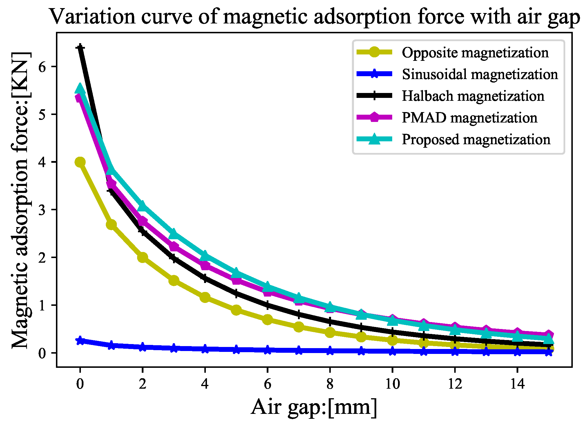
Figure 14 shows the variation curve for the adsorption force provided by the permanent magnetic chuck with the working air gap when different magnetization methods are used. When the working air gap is 1∼6 mm, the permanent magnetic chuck provides greater adsorption force by using the double-layer superposition Halbach array magnetization method.
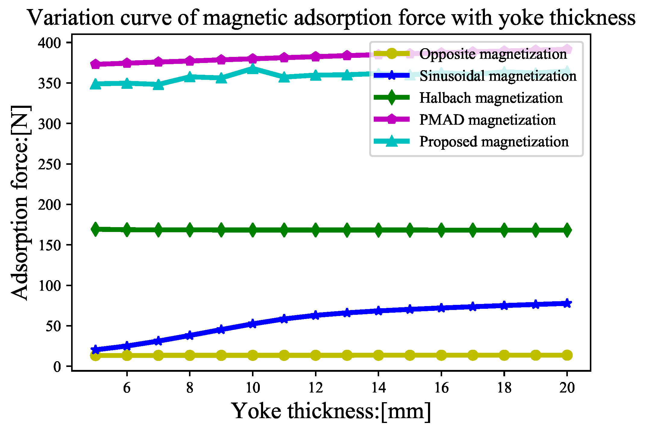
Figure 15 shows the curve of the adsorption force provided by the permanent magnetic chuck with the thickness of the yoke when different magnetization methods are used. The thickness of the yoke has little effect on the adsorption force provided by the permanent magnetic chuck.
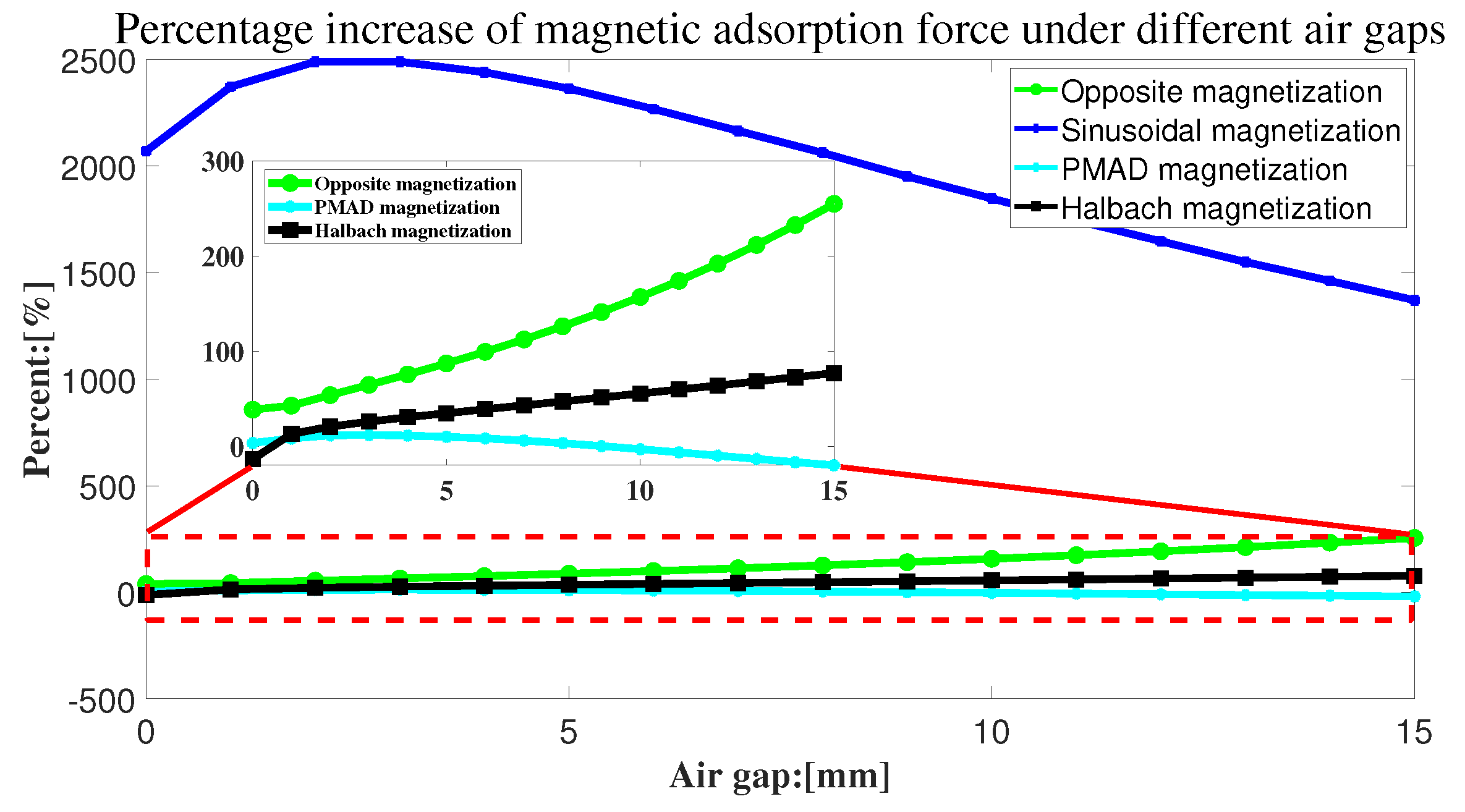
Figure 16 shows the curve comparing the increase in adsorption force with other magnetization methods when the double-layer superimposed Halbach array magnetization method is adopted for the permanent magnetic chuck under the same constraint conditions. Table 2 lists in detail the percent improvement achieved with the proposed magnetization method using different air gaps.
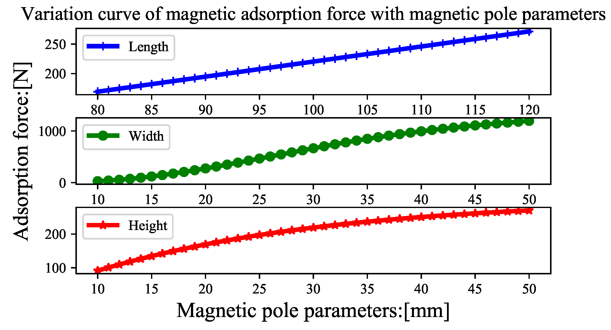
Figure 17 shows the relationship between the magnetic pole size parameter and the adsorption force when the double-layer superimposed Halbach array magnetization method is adopted for the permanent magnetic chuck.
Through the aforementioned analysis, we find that the adsorption force generated by the permanent magnetic chuck is related not only to the magnetization method but also to the size parameters of the magnetic poles. Based on the utilization rate of permanent magnets per unit mass, a new index is proposed for evaluating the rate of magnetic energy utilization by permanent magnetic chucks.
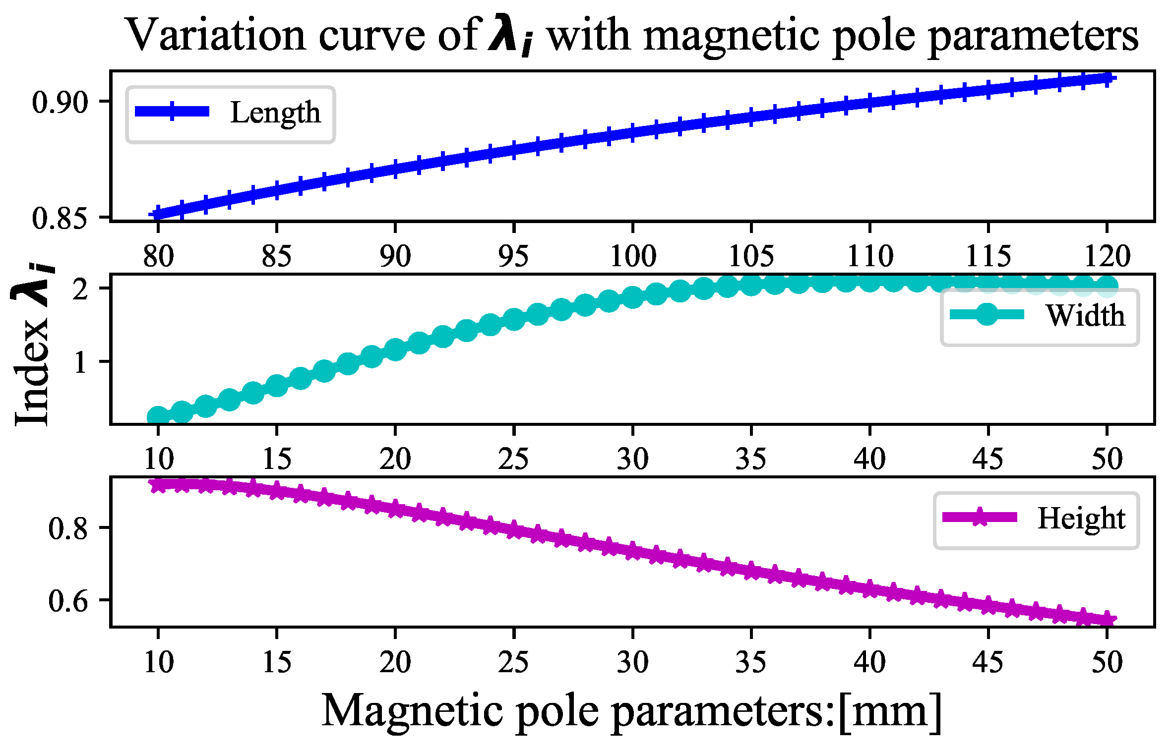
where is the magnetic pole density, and l, w and h are the length, width and height of the magnetic pole, respectively. Figure 18 shows the relationship between and l, w, h.
Figure 18 shows the variation curve for the magnetic energy utilization rate with magnetic pole size parameters. A linear positive correlation is observed between the magnetic energy utilization and the magnetic pole length parameter. However, the utilization of magnetic energy has a nonlinear relationship with the height and width parameters of magnetic poles.
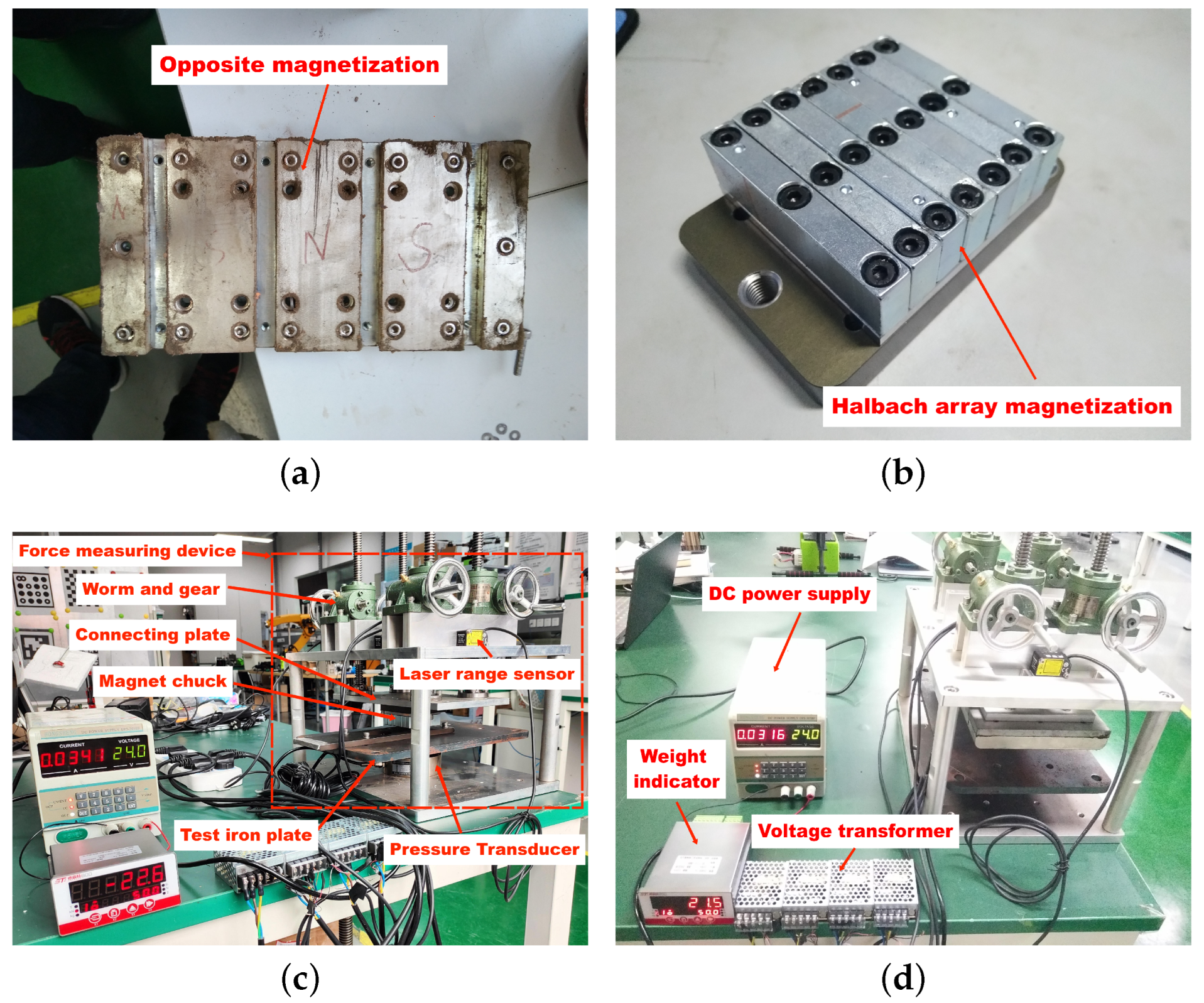
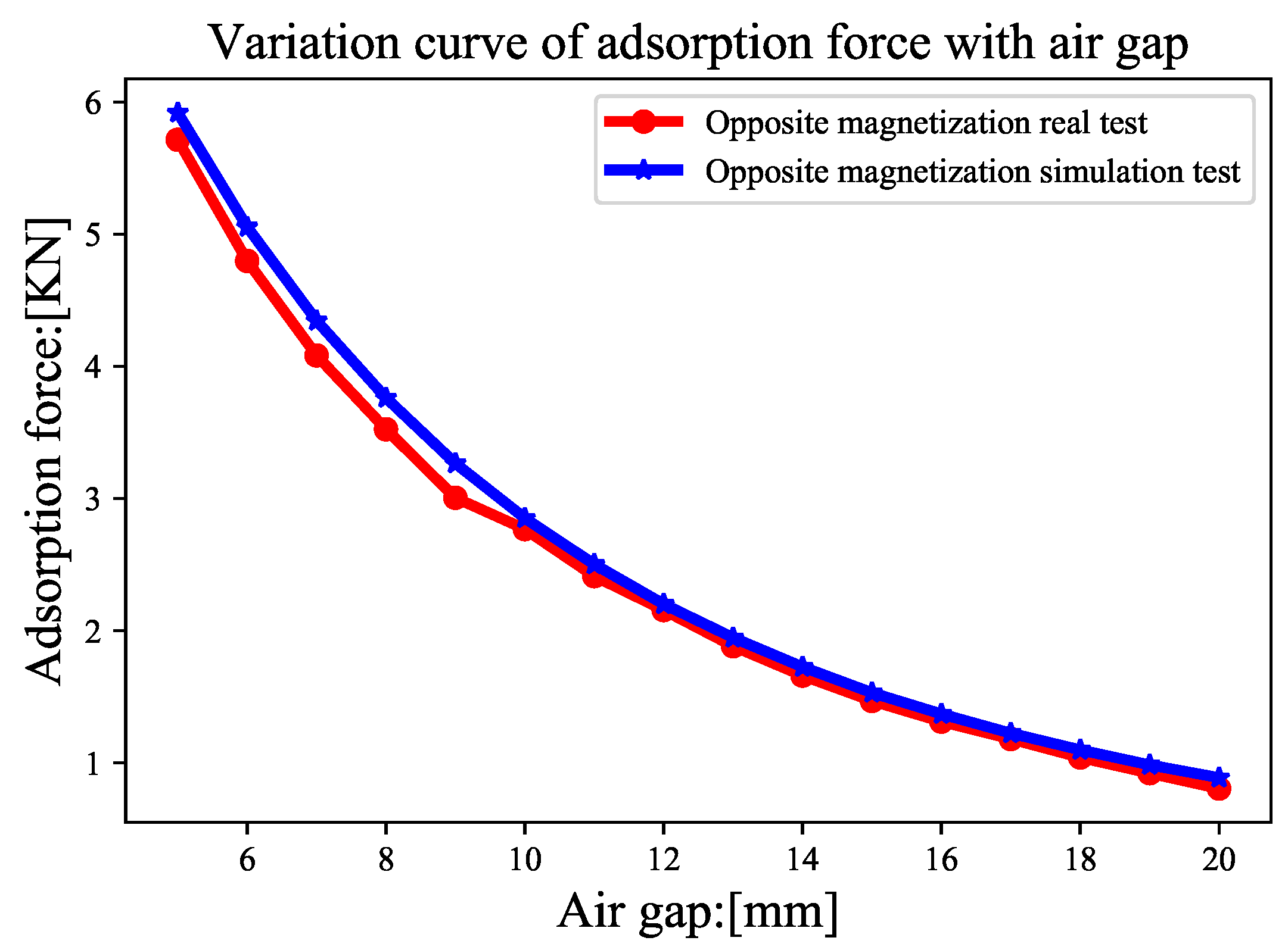
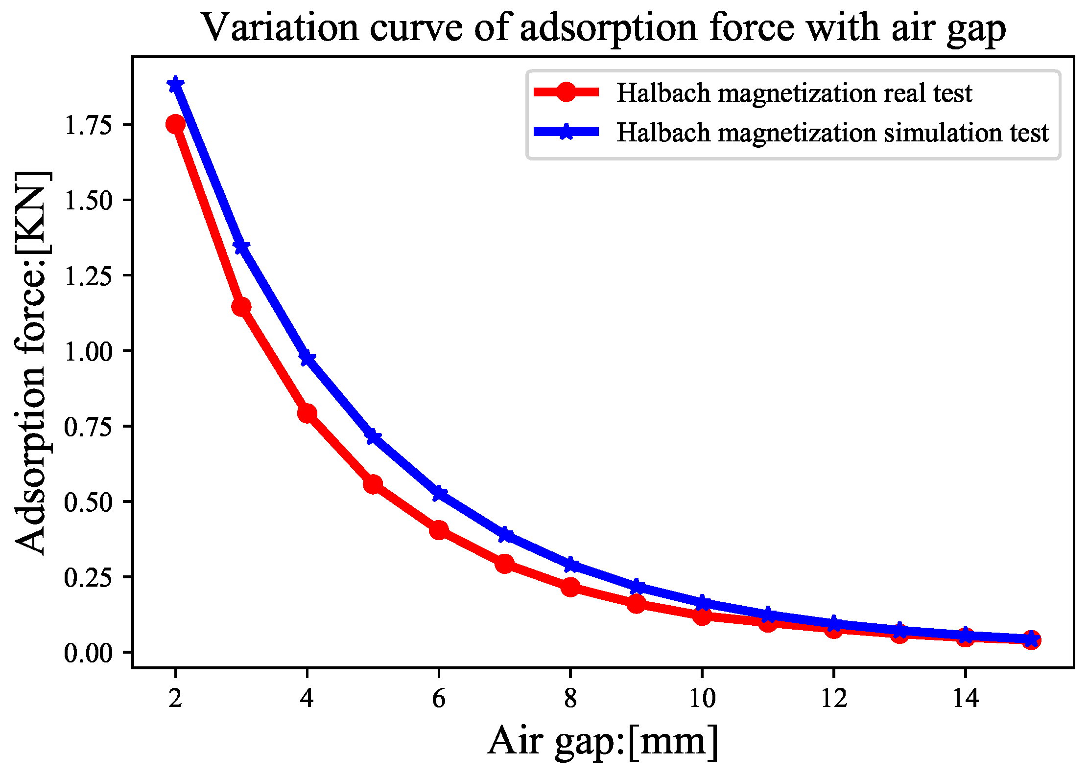
Figure 19a,b show the real permanent magnetic chuck designed using opposite magnetization and Halbach array magnetization, respectively. Figure 19c,d show the adsorption force test of the permanent magnetic chuck produced using the self-developed permanent magnetic chuck adsorption force test mechanism. Figure 20 and Figure 21 show the curves comparing the actual adsorption force and the simulated adsorption force of the permanent magnet chuck produced using the opposite magnetization and Halbach array magnetization methods, respectively. The simulation results are basically consistent with the actual test results.
Table 3 shows the comparison of the adsorption force provided by the permanent magnetic chuck produced with different magnetization methods under different working conditions of the wall-climbing robot. Under the same constraints, the double-layer superimposed Halbach array magnetization method provides greater adsorption force. The wall-climbing robot achieves more reliable adsorption.
Table 4 shows the quantitative comparison of the magnetic energy utilization ratio of the permanent magnet chuck produced using the magnetization method proposed in this paper compared with other methods at different working air gaps. The magnetization method proposed in this paper has a higher rate of magnetic energy utilization.
4. Discussion
First, the adsorption methods used by wall-climbing robots are summarized in this paper. Second, the force of the permanent magnetic adsorption wheel wall-climbing robot under typical working conditions is analyzed. Then, according to the requirements of the wall-climbing robot for the adsorption force, permanent magnetic chucks produced with different magnetization methods are designed. Finally, with the help of simulation software, the permanent magnetic chuck produced with different magnetization methods under the same constraint conditions is simulated and verified. Based on the simulation and actual test results, the magnetization method of the permanent magnetic chuck exerts a substantial effect on the adsorption force. Moreover, the effect of the magnetic pole size parameters of the permanent magnetic chuck on the adsorption force should not be ignored. In particular, the double-layer superimposed Halbach array magnetization method proposed in this paper provides a greater adsorption force than the current optimal PMAD magnetization method under the same constraints. This finding is very important for improving the reliable adsorption of wall-climbing robots. In the future, the design of a permanent magnetic chuck may be further optimized according to the newly defined permanent magnet utilization evaluation index.
5. Conclusions
This paper is based on the requirements of a noncontact permanent magnet wall-climbing robot for the inspection and maintenance task of a diversion penstock. First, a noncontact permanent magnet adsorption wheel wall-climbing robot is designed. Then, the magnetic circuit design of the permanent magnetic chuck of the wall-climbing robot is analyzed in detail, and a double-layer superposition magnetization method based on the Halbach array is proposed. At the same time, a new index to evaluate the utilization of magnetic energy is defined based on the size parameters of the magnetic pole that constitutes the permanent magnetic chuck. When the working air gap is 1∼6 mm, the double-layer superimposed Halbach array magnetization method increases the adsorption force by more than . At a working air gap of 1∼9 mm, the average magnetic energy utilization rate is increased by at least . Regarding the magnetic circuit design of permanent magnetic chucks, the main contributions of this paper are as follows:
- (1)
- A double-layer superposition Halbach array magnetization method is proposed.
- (2)
- An index for evaluating magnetic energy utilization based on magnetic pole size parameters is defined.
Author Contributions
Y.Z. (Yulong Zhang) conceived the original ideas, designed all the experiments and subsequently drafted the manuscript. E.G. and Y.Z. (Yanzheng Zhao) supervised the project and reviewed the manuscript. P.L. revised the format and charts of the manuscript. All authors have read and agreed to the published version of the manuscript.
Funding
This research was supported by the China Yangtze Power Co., Ltd. and Leader Harmonious Drive Systems Co., Ltd.
Data Availability Statement
The data that support the findings of this study are available from the corresponding author upon reasonable request.
Acknowledgments
We thank Engineer Baoshan Xie, Engineer Yunhai Zhou and Engineer Jianwei Li of Leader Harmonious Drive Systems Co., Ltd. for their help during the experiment.
Conflicts of Interest
The authors declare no conflict of interest.
References
- Nansai, S.; Mohan, R.E. A survey of wall-climbing robots: Recent advances and challenges. Robotics 2016, 5, 14. [Google Scholar] [CrossRef]
- Dethe, R.D.; Jaju, S. Developments in wall-climbing robots: A review. Int. J. Eng. Res. Gen. Sci. 2014, 2, 33–42. [Google Scholar]
- Chu, B.; Jung, K.; Han, C.S.; Hong, D. A survey of climbing robots: Locomotion and adhesion. Int. J. Precis. Eng. Manuf. 2010, 11, 633–647. [Google Scholar] [CrossRef]
- Vlasova, N.S.; Bykov, N.V. The problem of adhesion methods and locomotion mechanism development for wall-climbing robots. arXiv 2019, arXiv:1905.09214. [Google Scholar]
- Silva, M.F.; Machado, J.T. A survey of technologies and applications for climbing robots locomotion and adhesion. In Climbing and Walking Robots; Springer: Berlin/Heidelberg, Germany, 2010; pp. 1–22. [Google Scholar]
- Zhang, R. Design and Implementation of an Autonomous Climbing Robot. Ph.D. Thesis, Stanford University, Stanford, CA, USA, 2012. [Google Scholar]
- Silva, M.; Barbosa, R.; Oliveira, A. Magnetic wheeled climbing robot: Design and implementation. Comput. Intell. Decis. Mak. 2013, 61, 301–311. [Google Scholar]
- Schmidt, D.; Berns, K. Climbing robots for maintenance and inspections of vertical structures—A survey of design aspects and technologies. Robot. Auton. Syst. 2013, 61, 1288–1305. [Google Scholar] [CrossRef]
- Zhang, M.; Zhang, X.; Li, M.; Cao, J.; Huang, Z. Optimization Design and Flexible Detection Method of a Surface Adaptation Wall-Climbing Robot with Multisensor Integration for Petrochemical Tanks. Sensors 2020, 20, 6651. [Google Scholar] [CrossRef]
- Zhang, X.; Zhang, X.; Zhang, M.; Sun, L.; Li, M. Optimization Design and Flexible Detection Method of Wall-Climbing Robot System with Multiple Sensors Integration for Magnetic Particle Testing. Sensors 2020, 20, 4582. [Google Scholar] [CrossRef]
- Xu, Z.; Ma, P. A wall-climbing robot for labelling scale of oil tank’s volume. Robotica 2002, 20, 209–212. [Google Scholar] [CrossRef]
- Liu, J.; Yu, H.; Mei, L.; Han, B. Development of a new type of automatic magnetic particle inspection wall-climbing robot. Adv. Mech. Eng. 2021, 13, 168781402110473. [Google Scholar] [CrossRef]
- Mahmood, S.K.; Bakhy, S.H.; Tawfik, M.A. Magnetic–type Climbing Wheeled Mobile Robot for Engineering Education. In Proceedings of the 2nd International Scientific Conference of Al-Ayen University (ISCAU-2020), Online, Iraq, 15–16 July 2020. [Google Scholar]
- Howlader, M.O.F.; Sattar, T.P. Development of magnetic adhesion based climbing robot for non-destructive testing. In Proceedings of the 7th Computer Science and Electronic Engineering Conference (CEEC-2015), Colchester, UK, 24–25 September 2015. [Google Scholar]
- Lee, W.; Hirai, M.; Hirose, S. Gunryu III: Reconfigurable magnetic wall-climbing robot for decommissioning of nuclear reactor. Adv. Robot. 2013, 27, 1099–1111. [Google Scholar] [CrossRef]
- Eto, H.; Asada, H.H. Development of a Wheeled Wall-Climbing Robot with a Shape-Adaptive Magnetic Adhesion Mechanism. In Proceedings of the 2020 IEEE International Conference on Robotics and Automation (ICRA), Paris, France, 31 May– 31 August 2020. [Google Scholar]
- Silva, M.F.; Barbosa, R.S.; Oliveira, A.L. Climbing robot for ferromagnetic surfaces with dynamic adjustment of the adhesion system. J. Robot. 2012, 2012, 906545. [Google Scholar] [CrossRef]
- Howlader, M.O.F.; Sattar, T.P. Design and optimization of permanent magnet based adhesion module for robots climbing on reinforced concrete surfaces. Intell. Syst. Appl. 2016, 650, 153–171. [Google Scholar]
- Ding, W.; Wang, X.; Tang, C. Structural design of permanent magnet adsorption tracked ship wall-climbing robot. Hydromechatron. Eng. 2016, 44, 6–11. [Google Scholar]
- Gao, X.; Shao, J.; Dai, F.; Zong, C.; Guo, W.; Bai, Y. Strong magnetic units for a wind power tower inspection and maintenance robot. Int. J. Adv. Robot. Syst. 2012, 9, 189. [Google Scholar] [CrossRef]
- Espinoza, R.V.; de Oliveira, A.S.; de Arruda, L.V.R.; Junior, F.N. Navigation’s stabilization system of a magnetic adherence-based climbing robot. J. Intell. Robot. Syst. 2015, 78, 65–81. [Google Scholar] [CrossRef]
- Han, S.C.; Kim, J.; Yi, H.C. A novel design of permanent magnet wheel with induction pin for mobile robot. Int. J. Precis. Eng. Manuf. 2009, 10, 143–146. [Google Scholar] [CrossRef]
- Zhang, Y.; Dai, Z.; Xu, Y.; Qian, R. Design and adsorption force optimization analysis of TOFD-based weld inspection robot. In Proceedings of the Second International Conference on Mechanical, Electric and Industrial Engineering, Hangzhou, China, 25–27 May 2019. [Google Scholar]
- Fischer, W.; Tâche, F.; Siegwart, R. Inspection system for very thin and fragile surfaces, based on a pair of wall-climbing robots with magnetic wheels. In Proceedings of the 2007 IEEE/RSJ International Conference on Intelligent Robots and Systems, San Diego, CA, USA, 29 October–2 November 2007. [Google Scholar]
- Noh, M.; Kwon, E.; Park, S.H.; Park, Y.W. Modeling of attractive force by magnetic wheel used for mobile robot. Actuators 2020, 9, 67. [Google Scholar] [CrossRef]
- Xu, Z.; Xie, Y.; Zhang, K.; Hu, Y.; Zhu, X.; Shi, H. Design and optimization of a magnetic wheel for a grit-blasting robot for use on ship hulls. Robotica 2017, 35, 712–728. [Google Scholar] [CrossRef]
- Wu, M.; Pan, G.; Zhang, T.; Chen, S.; Zhuang, F.; Zhao, Y.-Z. Design and optimal research of a non-contact adjustable magnetic adhesion mechanism for a wall-climbing welding robot. Int. J. Adv. Robot. Syst. 2013, 10, 63. [Google Scholar] [CrossRef]
- Song, W.; Jiang, H.; Wang, T.; Ji, D.; Zhu, S. Design of permanent magnetic wheel type adhesion locomotion system for water jetting wall-climbing robot. Adv. Mech. Eng. 2018, 10, 1687814018787378. [Google Scholar] [CrossRef]
- Zhu, J.; Sun, Z.; Huang, W.; Chen, Q. Design of a Master-Slave Composite Wall-Climbing Robot System for Penstock Assembly Welding. In Proceedings of the 12th International Conference on Intelligent Robotics and Applications (ICIRA 2019), Shenyang, China, 8–11 August 2019. [Google Scholar]
- Shen, W.; Gu, J.; Shen, Y. Permanent magnetic system design for the wall-climbing robot. In Proceedings of the IEEE International Conference Mechatronics and Automation, Niagara Falls, ON, Canada, 29 July–1 August 2005. [Google Scholar]
- Yan, C.; Sun, Z.; Zhang, W.; Chen, Q. Design of novel multidirectional magnetized permanent magnetic adsorption device for wall-climbing robots. Int. J. Precis. Eng. Manuf. 2016, 17, 871–878. [Google Scholar] [CrossRef]
- Liu, G.; Hou, S.; Xu, X.; Xiao, W. Design of a New 1D Halbach Magnet Array with Good Sinusoidal Magnetic Field by Analyzing the Curved Surface. Sensors 2021, 21, 2522. [Google Scholar] [CrossRef]
- Wang, J.; Li, C.; Li, Y.; Yan, L. Optimization design of linear Halbach array. In Proceedings of the 2008 International Conference on Electrical Machines and Systems, Wuhan, China, 17–20 October 2008. [Google Scholar]
- Sim, M.S.; Ro, J.S. Semi-analytical modeling and analysis of Halbach array. Energies 2020, 13, 1252. [Google Scholar] [CrossRef]
- Lee, J.; Nomura, T.; Dede, E.M. Topology optimization of Halbach magnet arrays using isoparametric projection. J. Magn. Magn. Mater. 2017, 432, 140–153. [Google Scholar] [CrossRef]
- Halbach, K. Design of permanent multipole magnets with oriented rare earth cobalt material. Nucl. Instrum. Methods 1980, 169, 1–10. [Google Scholar] [CrossRef]
- Halbach, K. Strong rare earth cobalt quadrupoles. IEEE Trans. Nucl. Sci. 1979, 26, 3882–3884. [Google Scholar] [CrossRef]
- Yao, P.; Li, D. The magnetic field analysis and optimization of permanent magnetic adhesion device for a novel wall-climbing robot. In Proceedings of the International Technology and Innovation Conference 2009 (ITIC 2009), Xi’an, China, 12–14 October 2009. [Google Scholar]
- Guo, D.; Chen, Y. Optimization Design and Analysis of an Adaptive Variable Magnetic Adsorption Climbing Robot. In Proceedings of the 5th IFToMM International Conference on Mechanisms, Transmissions and Applications, School of Mechanical Engineering of Dalian University of Technology, Dalian, China, 9–11 October 2019. [Google Scholar]
- Hussain, S.; Sattar, T.; Salinas, E. Parameter analysis and design framework for magnetic adhesion wall-climbing wheeled robot. Int. J. Intell. Syst. Technol. Appl. 2012, 11, 102–116. [Google Scholar] [CrossRef]
Figure 1.
System composition and typical working state diagram of a wall-climbing robot. (a) Main components of the wall-climbing robot. (b) Typical motion states of wall-climbing robots inside a diversion penstock.
Figure 1.
System composition and typical working state diagram of a wall-climbing robot. (a) Main components of the wall-climbing robot. (b) Typical motion states of wall-climbing robots inside a diversion penstock.

Figure 2.
Schematic diagram of the static analysis under State A.

Figure 3.
Schematic diagram of the static analysis under State B.

Figure 4.
Schematic diagram of the static analysis under State C.

Figure 5.
Schematic diagram of the static analysis under State D.

Figure 6.
Schematic diagram of the double-layer Halbach array modeling.

Figure 7.
Magnetic lines and magnetic flux density distribution of an ideal Halbach array permanent magnetic chuck.
Figure 7.
Magnetic lines and magnetic flux density distribution of an ideal Halbach array permanent magnetic chuck.

Figure 8.
Permanent magnetic chuck magnetization method. (a) Opposite magnetization. (b) Halbach magnetization. (c) Sinusoidal magnetization. (d) PMAD magnetization.
Figure 8.
Permanent magnetic chuck magnetization method. (a) Opposite magnetization. (b) Halbach magnetization. (c) Sinusoidal magnetization. (d) PMAD magnetization.

Figure 9.
Simulation results for opposite magnetization. (a) Cloud map of the magnetic flux intensity on the test steel plate. (b) Cloud map of the magnetic flux intensity on the yoke.
Figure 9.
Simulation results for opposite magnetization. (a) Cloud map of the magnetic flux intensity on the test steel plate. (b) Cloud map of the magnetic flux intensity on the yoke.

Figure 10.
Simulation results for sinusoidal magnetization. (a) Cloud map of the magnetic flux intensity on the test steel plate. (b) Cloud map of the magnetic flux intensity on the yoke.
Figure 10.
Simulation results for sinusoidal magnetization. (a) Cloud map of the magnetic flux intensity on the test steel plate. (b) Cloud map of the magnetic flux intensity on the yoke.

Figure 11.
Simulation results for Halbach array magnetization. (a) Cloud map of the magnetic flux intensity on the test steel plate. (b) Cloud map of the magnetic flux intensity on the yoke.
Figure 11.
Simulation results for Halbach array magnetization. (a) Cloud map of the magnetic flux intensity on the test steel plate. (b) Cloud map of the magnetic flux intensity on the yoke.

Figure 12.
Simulation results for PMAD magnetization. (a) Cloud map of the magnetic flux intensity on the test steel plate. (b) Cloud map of the magnetic flux intensity on the yoke.
Figure 12.
Simulation results for PMAD magnetization. (a) Cloud map of the magnetic flux intensity on the test steel plate. (b) Cloud map of the magnetic flux intensity on the yoke.

Figure 13.
Simulation results for the proposed magnetization method. (a) Cloud map of the magnetic flux intensity on the test steel plate. (b) Cloud map of the magnetic flux intensity on the yoke.
Figure 13.
Simulation results for the proposed magnetization method. (a) Cloud map of the magnetic flux intensity on the test steel plate. (b) Cloud map of the magnetic flux intensity on the yoke.

Figure 14.
Effect of the magnetization mode on the magnetic adsorption force.

Figure 15.
Effect of the yoke thickness on the magnetic adsorption force.

Figure 16.
Comparison of the percent improvement with the magnetization method proposed in this paper and other methods.
Figure 16.
Comparison of the percent improvement with the magnetization method proposed in this paper and other methods.

Figure 17.
Variation curve of the magnetic adsorption force with magnetic pole parameters.

Figure 18.
Variation curve of the evaluated index with magnetic pole size parameters.

Figure 19.
Practical test of the permanent magnetic chuck. (a) Opposite magnetization of the permanent magnetic chuck. (b) Halbach magnetization of the permanent magnetic chuck. (c) Tension test of the Halbach magnetized permanent magnetic chuck. (d) Tension test of the opposite magnetized permanent magnetic chuck.

Figure 20.
Comparison of opposite magnetization adsorption forces.

Figure 21.
Comparison of Halbach magnetization adsorption forces.


Table 1.
Parameters of the NdFeB-N35 permanent magnet.
| Material | BH(max) | |||
|---|---|---|---|---|
| NdFeB-N35 | T | ≥859 KA/m | ≥955 KA/m | KJ/m |
Table 2.
Comparison of the percent improvement between the proposed magnetization method and other magnetization methods.
Table 2.
Comparison of the percent improvement between the proposed magnetization method and other magnetization methods.
| Air Gap [mm] | Opposite | Sinusoidal | PMAD | Halbach |
|---|---|---|---|---|
| 9 | 7.1968 | 19.5127 | 0.0060 | 0.5160 |
| 8 | 5.8543 | 20.6233 | 0.0364 | 0.4746 |
| 7 | 4.7136 | 21.6529 | 0.0637 | 0.4332 |
| 6 | 3.7550 | 22.6780 | 0.0863 | 0.3927 |
| 5 | 2.9481 | 23.6378 | 0.1034 | 0.3507 |
| 4 | 2.2676 | 24.4055 | 0.1157 | 0.3084 |
| 3 | 1.6860 | 24.8974 | 0.1233 | 0.2631 |
| 2 | 1.1779 | 24.8933 | 0.1179 | 0.2103 |
| 1 | 0.6931 | 23.7222 | 0.0865 | 0.1328 |
Table 3.
Comparison of the adsorption force of the magnetic chuck with the same size and produced different magnetization methods on the adsorption surface under different states.
Table 3.
Comparison of the adsorption force of the magnetic chuck with the same size and produced different magnetization methods on the adsorption surface under different states.
| State | Opposite | Sinusoidal | Halbach | PMAD | Proposed |
|---|---|---|---|---|---|
| A | 214.02 N | 133.29 N | 1191.96 N | 1300.20 N | 1551.24 N |
| B | 378.63 N | 167.19 N | 1698.33 N | 1644.69 N | 2069.70 N |
| C | 284.01 N | 148.89 N | 1420.56 N | 1460.31 N | 1788.87 N |
| D | 162.00 N | 119.88 N | 1003.11 N | 1160.52 N | 1348.80 N |
Table 4.
Comparison of the magnetic energy utilization of the proposed method compared with other methods at different working air gaps.
Table 4.
Comparison of the magnetic energy utilization of the proposed method compared with other methods at different working air gaps.
| Air Gap [mm] | Opposite | Sinusoidal | PMAD | Halbach |
|---|---|---|---|---|
| 9 | 0.4694 | 0.7627 | 0.0048 | 0.2729 |
| 8 | 0.5341 | 0.9125 | 0.0336 | 0.3079 |
| 7 | 0.6069 | 1.0955 | 0.0687 | 0.3464 |
| 6 | 0.6880 | 1.3206 | 0.1095 | 0.3888 |
| 5 | 0.7774 | 1.5993 | 0.1562 | 0.4328 |
| 4 | 0.8742 | 1.9466 | 0.2102 | 0.4777 |
| 3 | 0.9756 | 2.3835 | 0.2721 | 0.5164 |
| 2 | 1.0737 | 2.9388 | 0.3224 | 0.5311 |
| 1 | 1.1482 | 3.6595 | 0.3036 | 0.4470 |
| Mean() | 0.7942 | 1.8466 | 0.1646 | 0.4134 |
Publisher’s Note: MDPI stays neutral with regard to jurisdictional claims in published maps and institutional affiliations. |
© 2022 by the authors. Licensee MDPI, Basel, Switzerland. This article is an open access article distributed under the terms and conditions of the Creative Commons Attribution (CC BY) license (https://creativecommons.org/licenses/by/4.0/).
Share and Cite
MDPI and ACS Style
Zhang, Y.; Guan, E.; Li, P.; Zhao, Y. A Novel Magnetic Circuit Design Method for a Permanent Magnetic Chuck of a Wall-Climbing Robot. Energies 2022, 15, 6653. https://doi.org/10.3390/en15186653
AMA Style
Zhang Y, Guan E, Li P, Zhao Y. A Novel Magnetic Circuit Design Method for a Permanent Magnetic Chuck of a Wall-Climbing Robot. Energies. 2022; 15(18):6653. https://doi.org/10.3390/en15186653
Chicago/Turabian StyleZhang, Yulong, Enguang Guan, Peixing Li, and Yanzheng Zhao. 2022. "A Novel Magnetic Circuit Design Method for a Permanent Magnetic Chuck of a Wall-Climbing Robot" Energies 15, no. 18: 6653. https://doi.org/10.3390/en15186653
Note that from the first issue of 2016, this journal uses article numbers instead of page numbers. See further details here.