
Modeling of NOMA-MIMO-Based Power Domain for 5G Network under Selective Rayleigh Fading Channels
by
 , , ,
, , ,
Mohamed Hassan
1 ,
,
Manwinder Singh
1,*,
Khalid Hamid
2,
Rashid Saeed
3 ,
,
Maha Abdelhaq
4 and
Raed Alsaqour
5 1
Department of Wireless Communication, Lovely Professional University, Phagwara 144001, Punjab, India
2
Department Communication Systems Engineering, University of Science & Technology, Omdurman P.O. Box 30, Sudan
3
Department of Computer Engineering, College of Computers and Information Technology, Taif University, P.O. Box 11099, Taif 21944, Saudi Arabia
4
Department of Information Technology, College of Computer and Information Sciences, Princess Nourah bint Abdulrahman University, P.O. Box 84428, Riyadh 11671, Saudi Arabia
5
Department of Information Technology, College of Computing and Informatics, Saudi Electronic University, Riyadh 93499, Saudi Arabia
*
Author to whom correspondence should be addressed.
Energies 2022, 15(15), 5668; https://doi.org/10.3390/en15155668
Submission received: 12 July 2022
/
Revised: 1 August 2022
/
Accepted: 1 August 2022
/
Published: 4 August 2022
(This article belongs to the Special Issue Energy Efficiency in Wireless Networks)
Abstract
:The integration of multiple-input multiple-output (MIMO) and non-orthogonal multiple access (NOMA) technologies is a hybrid technology that overcomes a myriad of problems in the 5G cellular system and beyond, including massive connectivity, low latency, and high dependability. The goal of this paper is to improve and reassess the bit error rate (BER), spectrum efficiency (SE) of the downlink (DL), average capacity rate, and outage probability (OP) of the uplink (UL) in a 5G network using MIMO. The proposed model utilizes QPSK modulation, four users with different power location coefficients, SNR, transmit power, and two contrasting bandwidths 80 and 200 MHz under selective frequency Rayleigh fading channels. The proposed model’s performance is evaluated using the MATLAB software program. The DL results found that the BER and SE against transmitted power showed the MIMO-NOMA enhanced the BER performance for the best user U4 from 10−1.7 to 10−5.2 at 80 MHz bandwidth (BW), and from 10−1.5 to 10−5 at 200 MHz for transmitting power of 40 dBm. In contrast, the SE performance for the best user U4 is enhanced from 24 × 10−3 to 25 × 10−3 bits/second/Hz at 80 MHz BW and from 19.8 × 10⁻³ to 20 × 10−3 bps/Hz at 200 MHz BW. Although the outcomes for the UL were obtained in terms of average capacity rate and OP versus SNR at 80, and 200 MHz BW, the MIMO-NOMA result showed that the average capacity rate for the best user U4 performance improves by 12 bps/Hz for 1 dB SNR and the OP is reduced by 15 × 10−3 for 80 MHz BW and by 12 × 10−3 for 200 MHz BW at an SNR of 0.17 dB. As the BW increased the BER, the average capacity rate increased while the SE and OP decreased. For both DL/UL NOMA with and without MIMO, closed-form expressions for BER, SE, average capacity rate, and OP were obtained. All users’ performance, even those whose connections were affected by interference or Rayleigh fading channels significantly improved, when MIMO-NOMA was implemented.
1. Introduction
Due to the compelling multimedia applications and the popularity of smart mobile devices, wireless communication has developed at a breakneck pace over the last decade [1,2]. Non-orthogonal multiple access (NOMA) has been offered as a possible strategy for achieving mass accessibility with keeping spectral efficiency [3,4]. NOMA achieves multiple access by modifying the power level of overlay user signals at the transmitter and receiving the signal using successive interference cancellation (SIC) in receivers, with noise-limiting user rates for better channels and bandwidth-limiting user rates for bad channels [5,6,7,8]. SIC is implemented at the power user level because NOMA is sequential interference cancellation, allowing the powerful user to detect and discard messages from users with weaker channel conditions. Data from users with better channel conditions is considered interference by the weaker user [9]. In the NOMA downlink (DL) system, multiple users share the same time, coding, and frequency resources due to the multiplexing of the power field. The base station (BS) sends an overlay signal to each user, which includes a signal for all users [10]. Because users no longer have to wait for an orthogonal resource block to become available, NOMA can accomplish huge connections while drastically lowering transmission delay [11]. As a result, NOMA with SIC is a promising multiple-access approach in the next-generation communication system [12]. NOMA is a wireless technology that can meet the demands of today’s wireless environment [13]. The analysis of different access technologies is still in its early phases [14]. The main leading research group is working on determining the spectrum’s efficiency because all features are constantly generated [15,16].
In uplink (UL) NOMA, a group of users simultaneously sends their signals to their associated BS [17,18]. Intra-cluster interference, as a result, impacts a user’s received signal, which is determined statically by other users’ channel data [19]. To reduce interference, the BS could use SIC to decode signals. Separate message signals with an adequate power variance must arrive at the receiver BS to correctly utilize the SIC technique. This is commonly handled in the DL by employing different scales at the transmitter. Furthermore, such values are superfluous because the UL channel gains already offer enough separation between the received signals. The standard UL transmits power control, which is supposed to balance the received signal levels of users, is not recommended for UL NOMA transmissions because it may reduce channel distinctness [20,21,22,23,24].
Using several antennas in both the transmitter and receiver can considerably increase the capacity of a radio communication channel. That is, many separate channels can be managed in the same bandwidth using multiple-input multiple-output (MIMO) technology with these antennas, but only if the propagation environment is sufficiently rich [25,26]. Although the use of MIMO techniques adds another dimension to enhance efficiency, research into combining MIMO and NOMA has recently a lot of interest [26,27].
The additive white Gaussian noise (AWGN) and Rayleigh fading channels were investigated for the accurate expression of the BER rate generated in a closed form for BPSK modulation in the perfect and deficient SIC states for the DL NOMA network. However, it did not include parameters that influence the BER, such as distance and power location coefficients in [28]. Three power assignment strategies are proposed to improve NOMA SE by optimizing the given power to each NOMA in [29,30]. The impact of interference on users of the energy allocation process, nevertheless, has not been investigated or examined. Investigate the attainable rates of UP NOMA with a synchronized transmission in [31] and estimate both the upper and lower bounds of a synchronized NOMA system’s possible rates, illustrating that the measured lower bound is approximately the rate achievable by conventional synchronized NOMA systems. Nonetheless, each user is provided with a relatively limited number of transmitted symbols, which may lead to inaccurate findings. The ergodic rate achievable in [23,24] is monitored and checked to ensure optimal performance of the encoder and pre-detection systems that simplify decoding in the dual receive channels used for DL and UL transmissions. Nevertheless, the number of users is insufficient to confirm the optimal situation, and there has been no research into the method’s impact on OP or BER, for example.
In this paper, we examine the impact of varying the bandwidth and the number of antennas in a 5G network on the bit error rate (BER) and spectrum efficiency (SE) of the downlink, and the average capacity rate and outage probability (OP) of the uplink in a network subject to Rayleigh fading. During the analytical process, the integral expressions of the BER, SE, capacity rate, and OP were generated. In addition, modeling is used to verify all the potential configurations of the system. The following are some of the research’s most significant contributions:
- Two different bandwidths (BWs) for the NOMA system over a Rayleigh fading channel are proposed and investigated;
- Improvements in the system have been examined when NOMA and MIMO are used together to handle four users.
The article addresses the NOMA technique which is considered one of the main bullets of 5G technology. Our main innovative idea in the article is remodeling NOMA-MIMO for the power domain for a higher data rate, capacity, and throughput. This has been performed by proposing a new power domain scheme for NOMA-MIMO.
The remainder of the paper is structured as follows: Section 2 contains previous and related works. Section 3 discusses the proposed system mathematical model. Simulation and simulation parameters are presented in Section 4. The results and discussions are presented in Section 5 and, finally, Section 6 concludes the paper and presents further future work.
2. Related Work
Multiple beams forming with a single carrier are utilized in NOMA systems to accommodate numerous users as a two-stage beam forming solution for modular beam forming vectors, according to the author in [32]. A reduced total transmission packet shaping issue is built to identify both users’ packet-shaping vectors and power.
The author in [33], established successful precoding and detecting procedures to produce a considerable difference between users’ effective channel gains, allowing NOMA’s potential to be achieved even when the users’ initial channel conditions are comparable. The author investigated the performance of MIMO-NOMA when numerous users are aggregated into a group, finding that MIMO-NOMA outperforms MIMO-OMA in terms of total channel capacity and total practical capacity [34].
Using statistical channel state information at the transmitter, the ergodic capacity maximization problem for selective Rayleigh fading MIMO-NOMA systems was investigated in [30]. The MIMO-NOMA schemes greatly outperform the conventional OMA scheme, according to numerical results.
Following a review of the concept of integrating NOMA downlink with MIMO, an experiment was carried out to assess the performance of NOMA downlink combined with MIMO under realistic settings in [35]. In UL, the user connection. The author investigated NOMA in [36], considering numerous specified power allocation techniques. It has been demonstrated that NOMA with the suggested user pair technique outperforms NOMA with the previously described signal realignment.
The author looked in [37] at many NOMA DL and UL user power field-based communication systems with different fading bindings for all users who can follow one of the many conceivable distributions. At high SNRs, analytical expressions of the OP for the NOMA DL and UL systems were derived.
An unmanned aerial vehicle-assisted NOMA network with UL and DL transmissions was explored, and analytical expressions of OP as the major measure were derived in [38]. The author explores a novel UL/DL NOMA system with a uniform relay and set decode order that involves the use of statistical channel state information, resulting in enhanced fairness and applicability [39]. The author evaluated the potential of UL and DL resource utilization, adaptive control, and power control for wireless communications systems under the assumptions of in-band full-duplex BSs, NOMA operation, and queue stability limitations.
A method is proposed for solving by finding a correlation similarity in [40]. The efficacy of different NOMA plots over the tapping delay line channel in both normal and fast UE speed and correlation-level modeling was explored by the author in [40,41,42]. With UE’s normal and fast speed, NOMA methods work differently.
3. System Model
3.1. DL Scenario
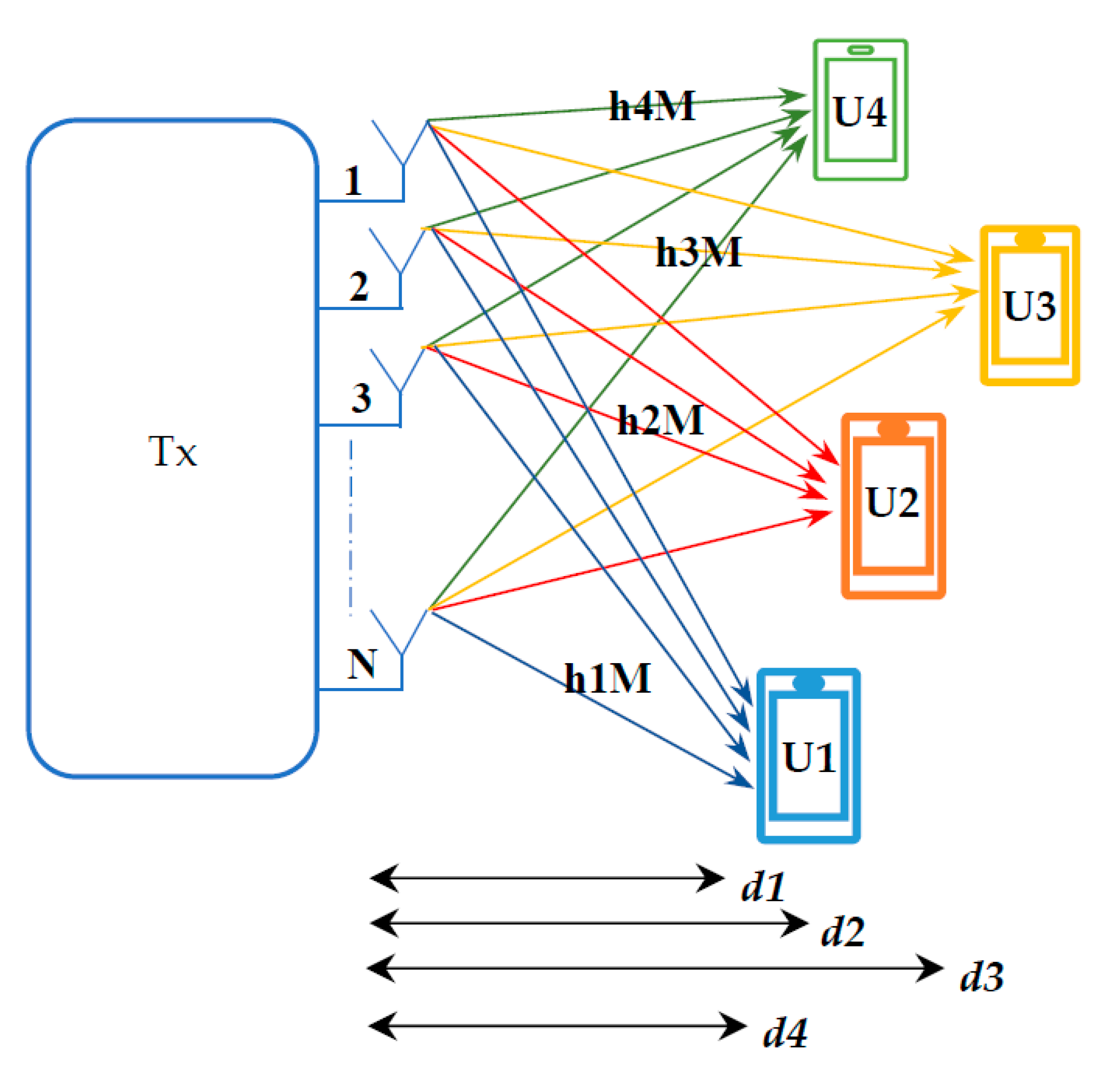
Consider a wireless network with four DL NOMA users and a 64 × 64 MIMO system (as depicted in Figure 1). are the four users with different bandwidths of 80 and 200 MHz [43]. Let represent their various BS distances, indicating the preferred order. Depending on the distance, is the weak/far user while U4 is the strong/near user from BS. Let identify which selective Rayleigh fading coefficients they correspond to .
The total Rayleigh fading channel for each user is given by [44]:
where, is the number of users, and is the number of channels. and show their respective power coefficients. According to the NOMA (power domain) principles, the lower user must have more power and the better user should have less power [45,46]. As a result, the power coefficients must be modified as Let and be the QPSK-formed messages to send to BS . The BS’s encoded overlay signal is then given by as in [47].
decodes directly when it has maximum power, interfering with the 2nd, 3rd, and 4th signals. As a result, the first possible rate is
The obtained rate is for after SIC eliminated data.
The achieved rate is for after SIC deleted U1 and data.
The acquired rate is for after SIC deleted data, data, and data.
To calculate the spectrum efficiency.
where the is spectrum efficiency, is the throughput and is the bandwidth.
3.2. UL Scenario
The power domain multiplexing for uplink NOMA is almost entirely different. In downlink NOMA, the BS employed superposition coding to offer power domain multiplexing; however, the user’s transmit power is limited only by their battery capacity in the uplink. That is, both users can transmit at full strength. Changes in the users’ channel gains cause variation in the power domain at the receiver side of BS.
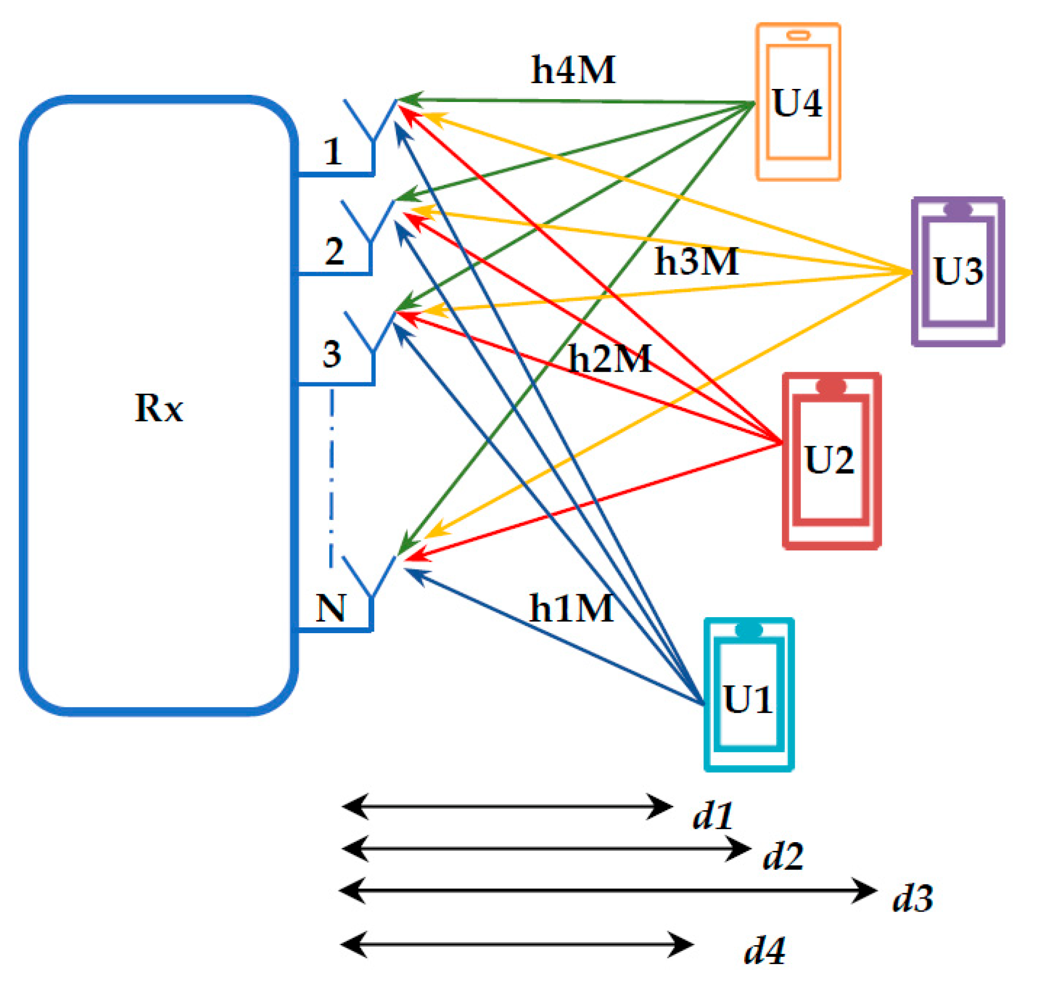
Let and represent the messages that will be sent by four UL NOMA users , accordingly. Suppose that both users’ signals have the same strength and consider the 64 × 64 MIMO system and BW equal to 80 MHz on a wireless network (as depicted in Figure 2). Let denote the various BS distances, with being the preferred order. from BS is the weak/far user, while is the strong/near user, depending on the distance. Let determine which selective Rayleigh fading coefficients they relate to
The total Rayleigh fading channel for each user is given by:
where is the number of users and is the number of channels.
The signal was received at the BS.
where is the noise power.
3.2.1. Capacity Rates Achievable of Four Users UL NOMA
The signal from the close user is decoded first, with the signal from the distant users being treated as interference. Therefore, the rate at which the BS can decode the data of a nearby user is, according to [48,49].
After the SIC has been calculated, the maximum rate can be obtained.
After the SIC has been calculated, the maximum rate that can be accomplished
After the SIC has been calculated, the maximum rate of U1 can be achieved.
3.2.2. OP of Four Users UL NOMA
Consider that the four users have different target rates.
The capacity is calculated as follows:
capacity is calculated as follows:
capacity is calculated as follows:
capacity is calculated as follows:
For , the OP condition is:
The OP of :
For , the OP condition is:
The OP of :
For , the OP condition is:
The OP of :
For , the OP condition is:
The OP of :
where is the number of transferred samples.
4. Simulation Parameters
5. Results and Discussions
5.1. The Outcomes of the DL Scenario
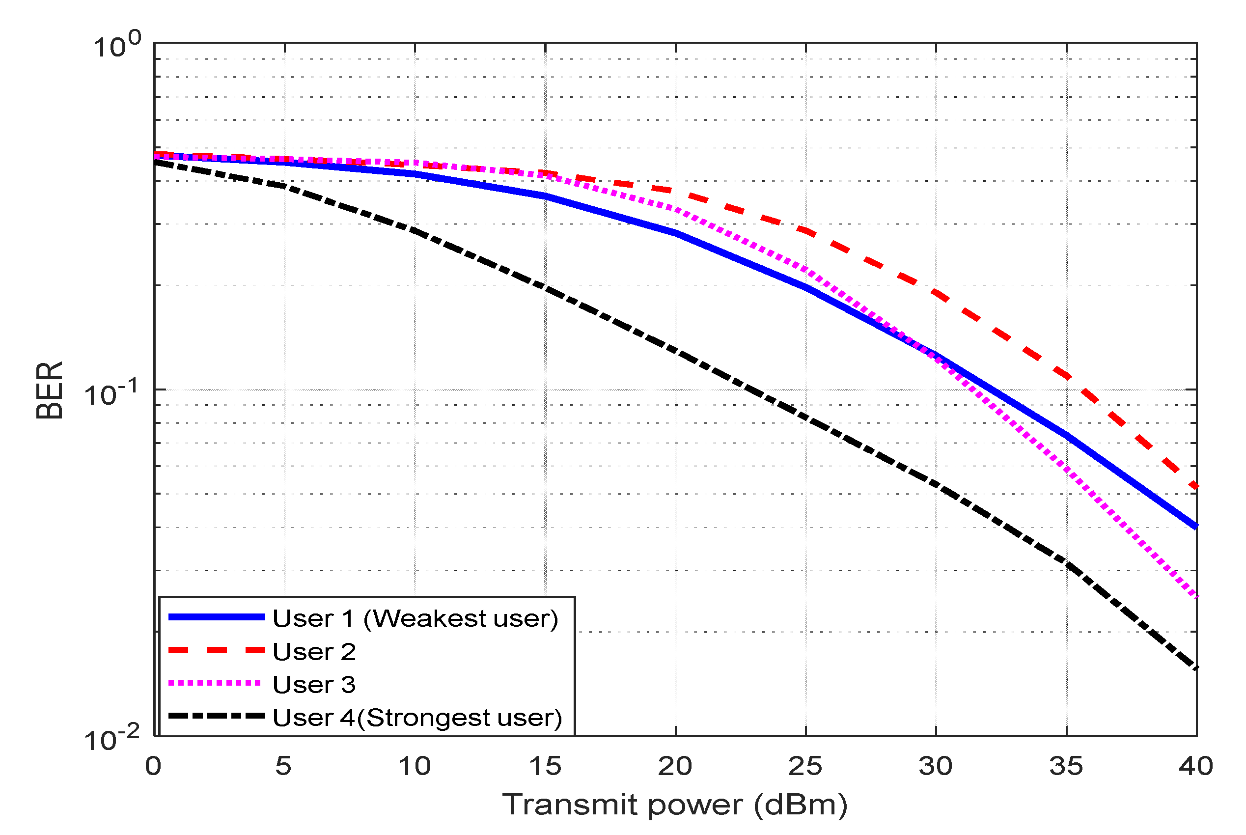
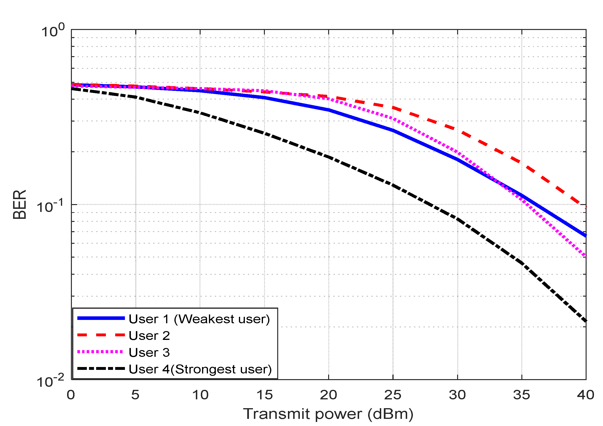
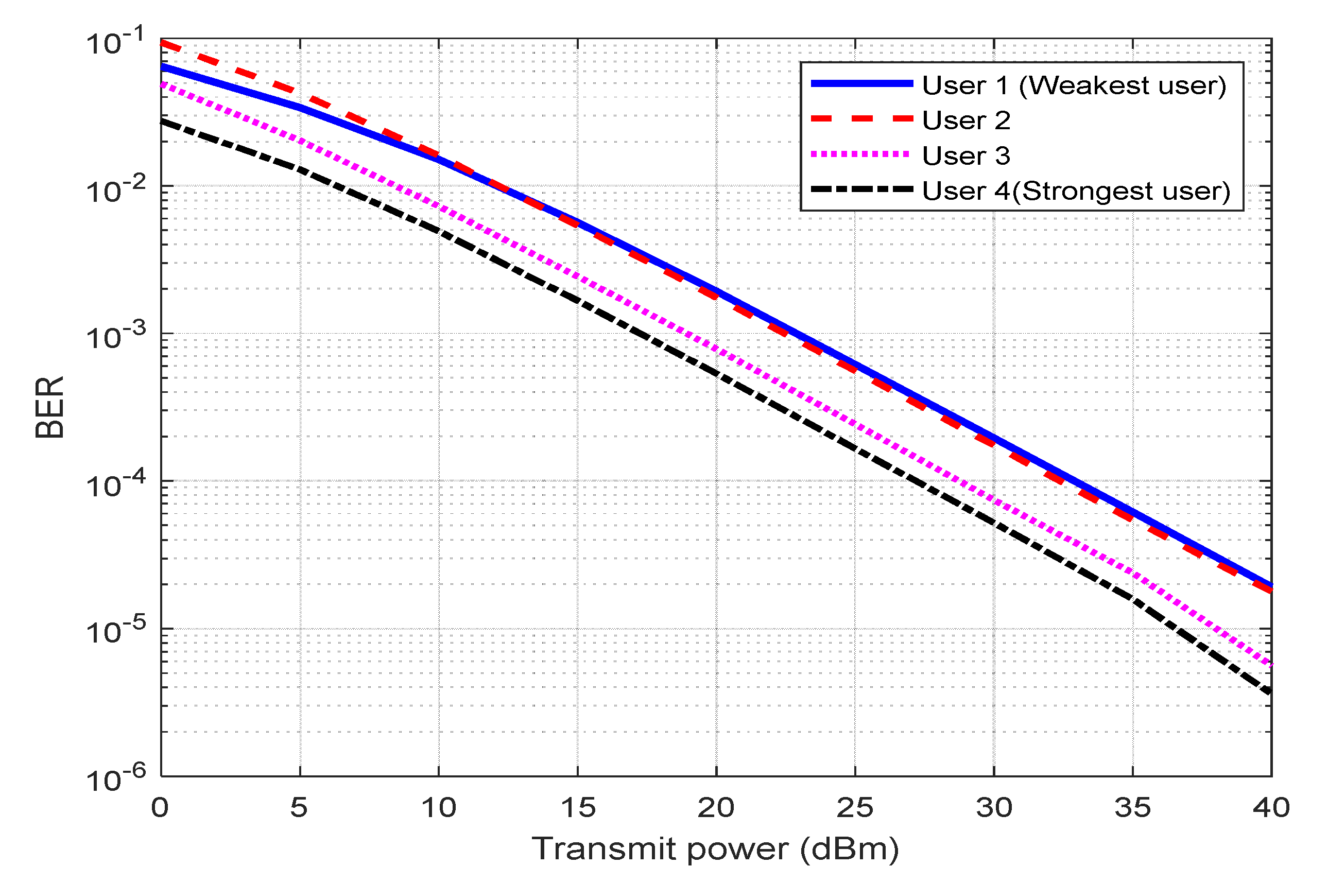
The DL NOMA system results showed that using 64 × 64 MIMO improved the SE and BER performance. The near–far user’s problem is also resolved, where the performance of all users becomes close to each other’s for different power location coefficients, transmitted power, and distance parameters when compared without MIMO DL NOMA performance. Figure 3 depicts the DL NOMA BER performance versus transmitted power at 80 MHz BW. The findings indicate that the BER performance decreases as transmitted power increases. As an outcome, the U4 BER performance is best for all users, because U4 is the nearest one. At a transmitter power of 25 dBm, the BER rate for U1, U2, U3, and U4 is found to be 20%, 28%, 22%, and 8%, respectively. Figure 4 shows the DL NOMA BER performance against transmitted power at 200 MHz BW; the findings show that the BER performance decreases as transmitted power increases. As a result, the U4 BER performance is best when compared with all users because U4 is the nearest one. At a transmit power of 25 dBm, the BER rates for U1, U2, U3, and U4 are found to be 27%, 36%, 31%, and 13%, respectively. The 64 × 64 MIMO DL NOMA enhances the performance of BER for the best user U4 from 10−1.7 to 10−5.2 at 80 MHz then, from 10−1.5 to 10−5 at 200 MHz BW at a transmitter power of 40 dBm in Figure 4. In contrast, the SE performance for the best user U4 is improved by 8 × 10⁻³ bps/Hz for 80 MHz BW and by 10−2 bps/Hz for 200 MHz BW at a transmitter power of 40 dBm. The UL NOMA systems results obtained using 64 × 64 MIMO enhanced the average capacity rate performance by 12 bps/Hz, reduced the OP by 15 × 10−3 for 80 MHz BW at SNR of 1 dB.
At 80 MHz BW and 64 × 64 MIMO, Figure 5 shows the DL NOMA BER performance versus transmitted power. When transmitted power is 20 dBm, the BER rate for U1, U2, U3, and U4 is found to be 19 × 10−4, 18 × 10−4, 8 × 10⁻⁴, and 5 × 10⁻⁴, respectively. Figure 6 shows the DL NOMA BER performance against transmitted power at 200 MHz BW and 64 × 64 MIMO, at a transmitted power of 25 dBm, the BER rates for U1, U2, U3, and U4 are found to be 46 × 10−4, 43 × 10−4, 19 × 10−4, and 7 × 10⁻⁴, respectively. The MIMO system reduces the BER performance.
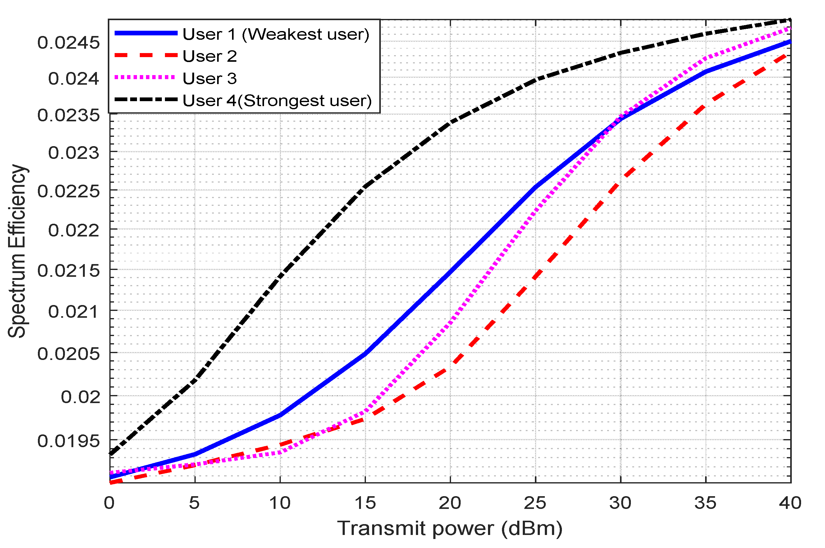
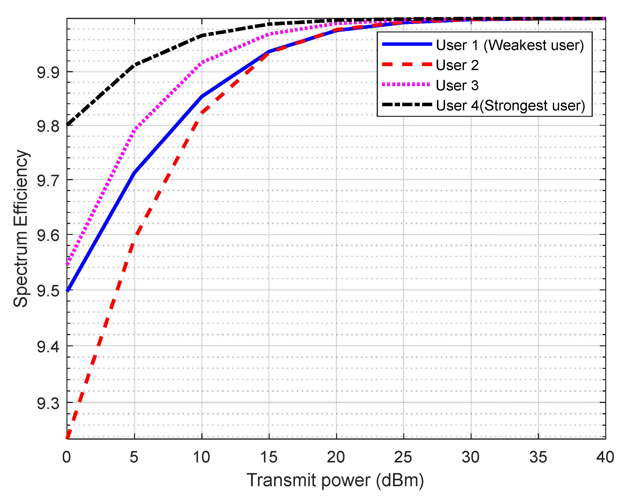
Figure 7 shows the performance of the DL NOMA SE vs. transmitted power at 80 MHz BW, with the outcomes demonstrating that SE performance improves as transmitted power increases. As an outcome, the U4 BER performance is best for all users, because U4 is the nearest one. There is a clear separation of SE performance for all users from one another until the transmitted power reaches 5 dBm. Figure 8 depicts the DL NOMA SE performance versus transmitted power at 200 MHz BW, with the results indicating that increasing transmitted power improves SE performance. The U4 SE performance is best when compared with all users because U4 is the nearest one. The outcomes are superior to those of the best U2 users in [38], with an improvement rate of 10−2.3 in the BER.
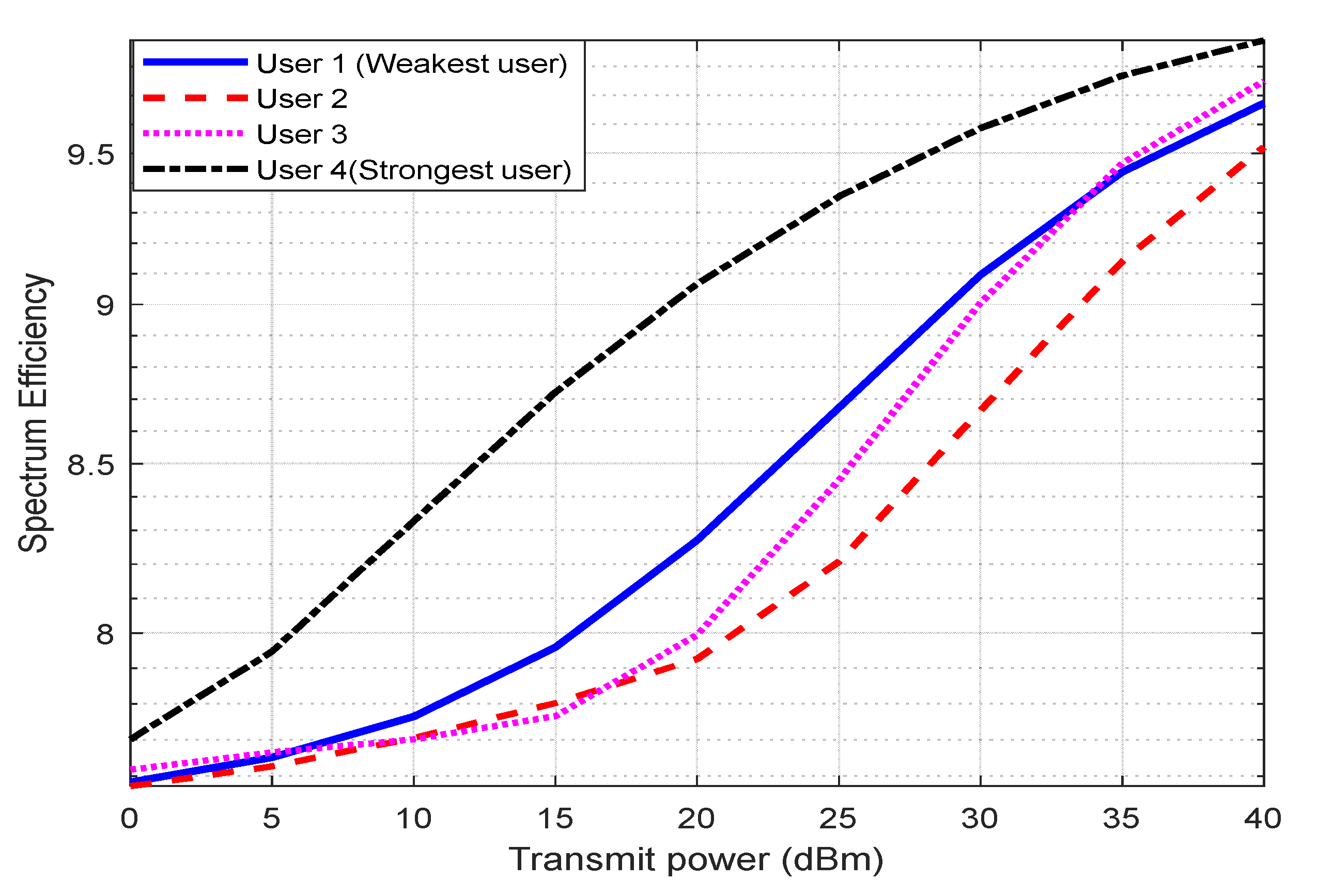
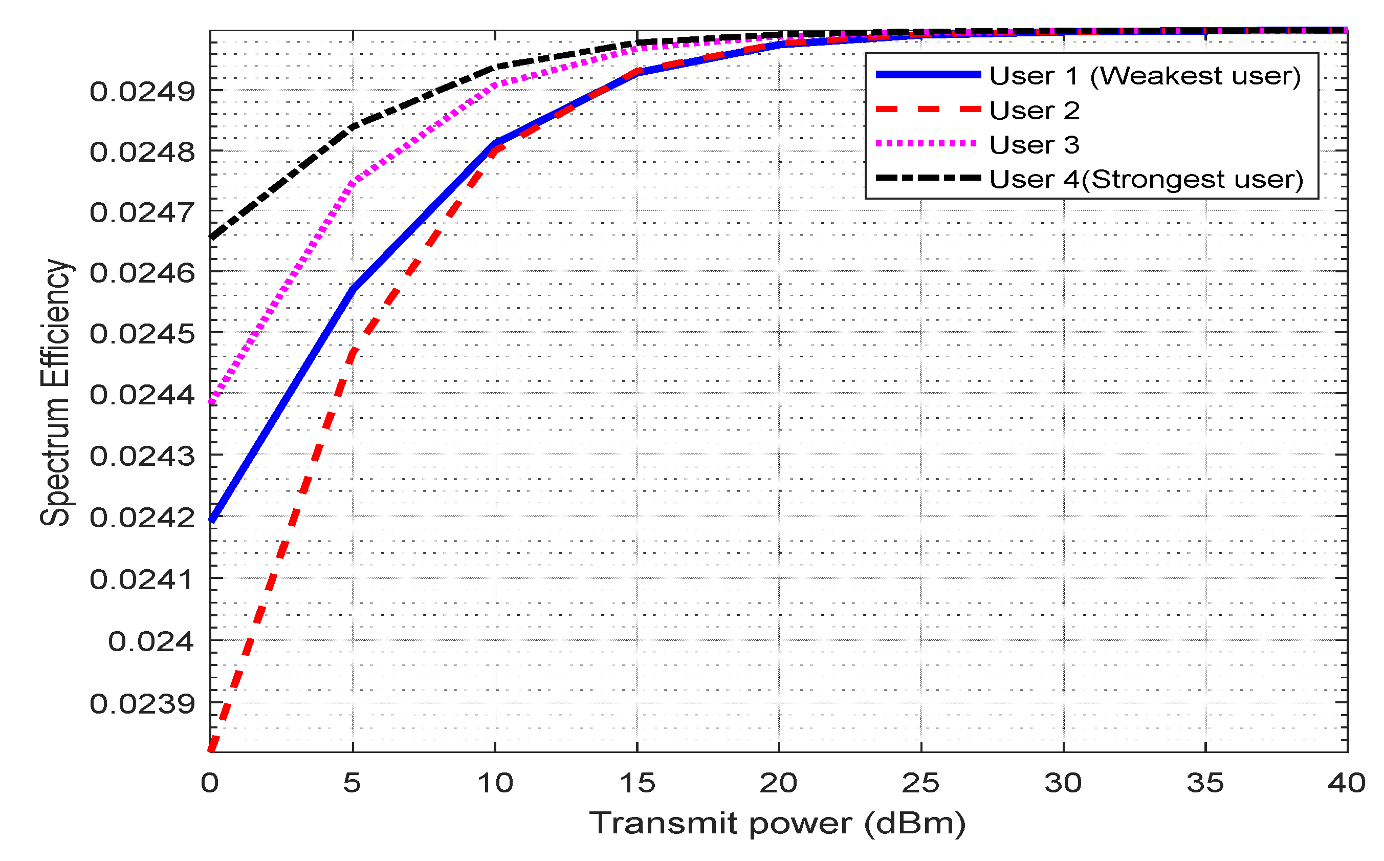
The performance of the DL NOMA SE in terms of transmitted power at 80 MHz BW and 64 × 64 MIMO is shown in Figure 9. At the transmitting power of 5 dBm, the SE for all users is relatively close. Figure 10 depicts the DL NOMA SE performance versus transmit power at 200 MHz BW and 64 × 64 MIMO. At a transmitter power of 10 dBm, the SE for all users is relatively close. The MIMO improved SE performance.
5.2. The Outcomes of the UL Scenario
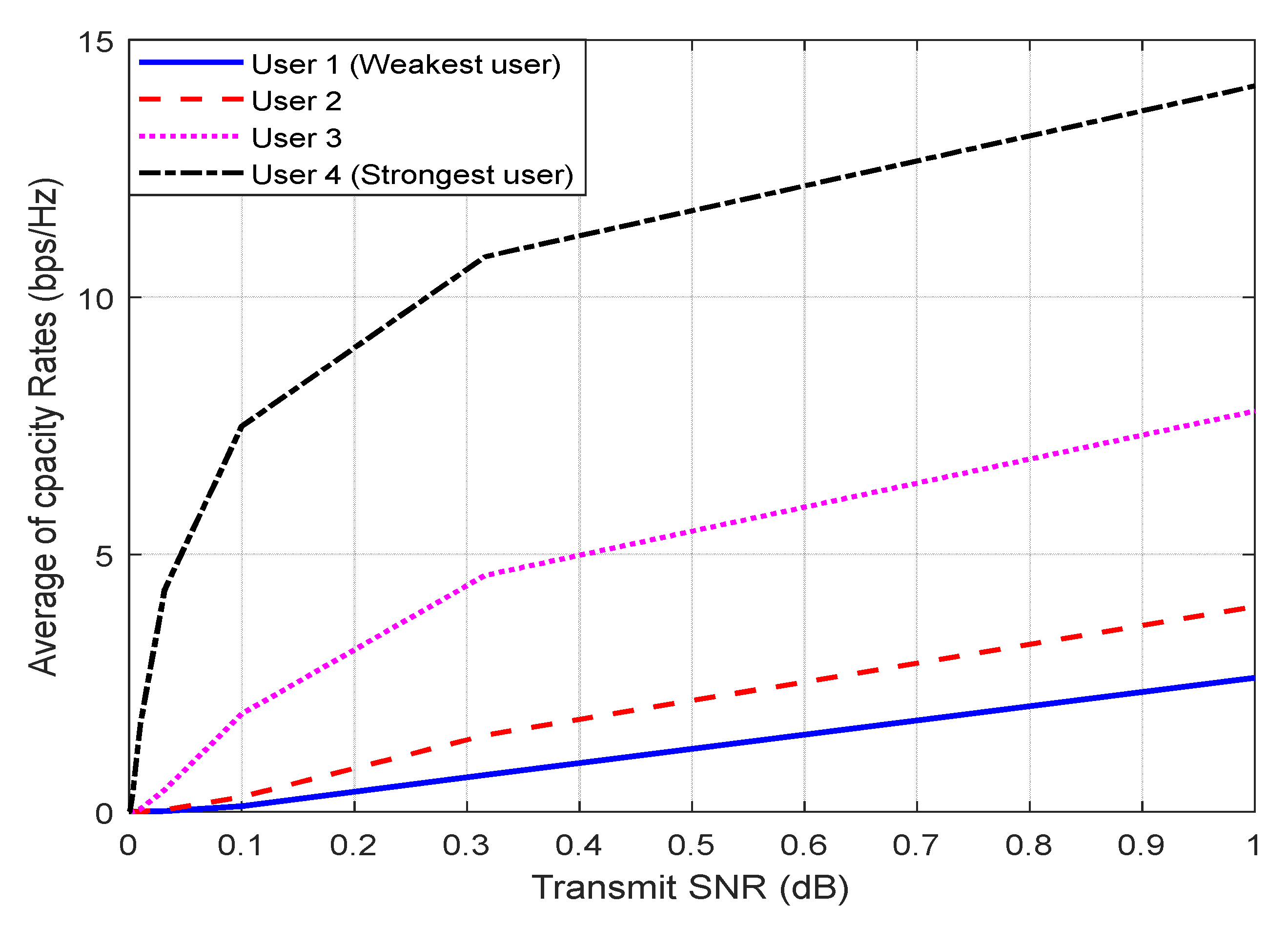
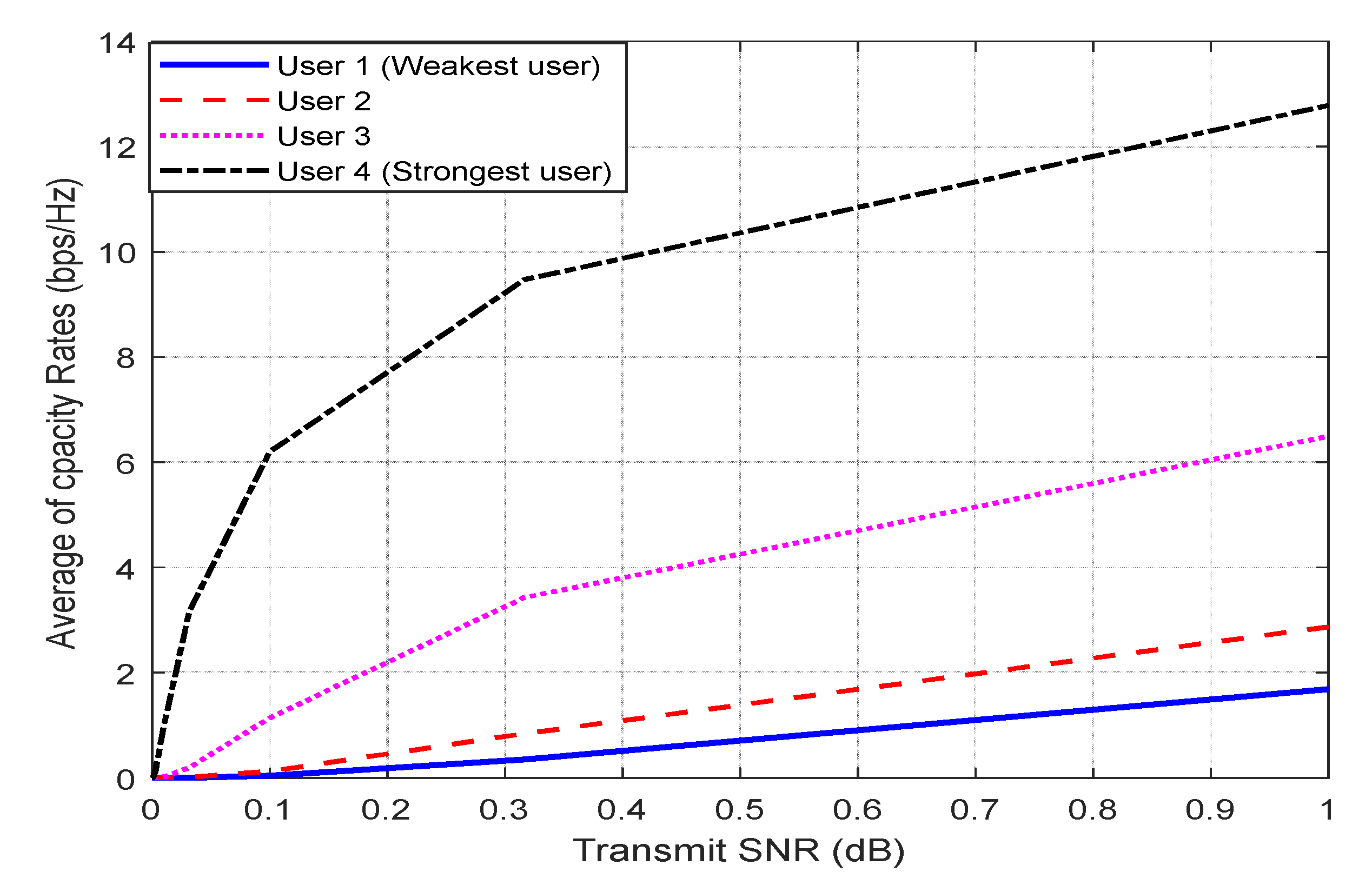
The UL NOMA average capacity rate vs. SNR at 80 MHz BW is depicted in Figure 11. The result shows that the average capacity rate for U4 is best for all users because U4 is the closest. At SNR of 1 dB, the average capacity rate for U1, U2, U3, and U4 is found to be 1.6873, 2.8718, 6.4960, and 12.7814, respectively. Figure 12 shows the UL average capacity rate against SNR at 200 MHz BW. At SNR of 1 dB, the average capacity rate for U1, U2, U3, and U4 is found to be 2.6015, 3.9841, 7.7910, and 14.1068, respectively. The results reveal that when an SNR increases, the average capacity rate performance rises as well. The 64 × 64 MIMO improved the performance of the capacity average rate by 12 bps/Hz and reduced the OP by 15 × 10−3 for 80 MHz BW at SNR of 1 dB; it enhanced the performance capacity average rate by 12 bps/Hz, and decreased the OP by 12 × 10−3 for 200 MHz BW at 0.17 dB SNR for the user U4. In general, an increase in BW increases the capacity average rate and BER while decreasing OP and SE. MIMO significantly enhances the throughput of all users.
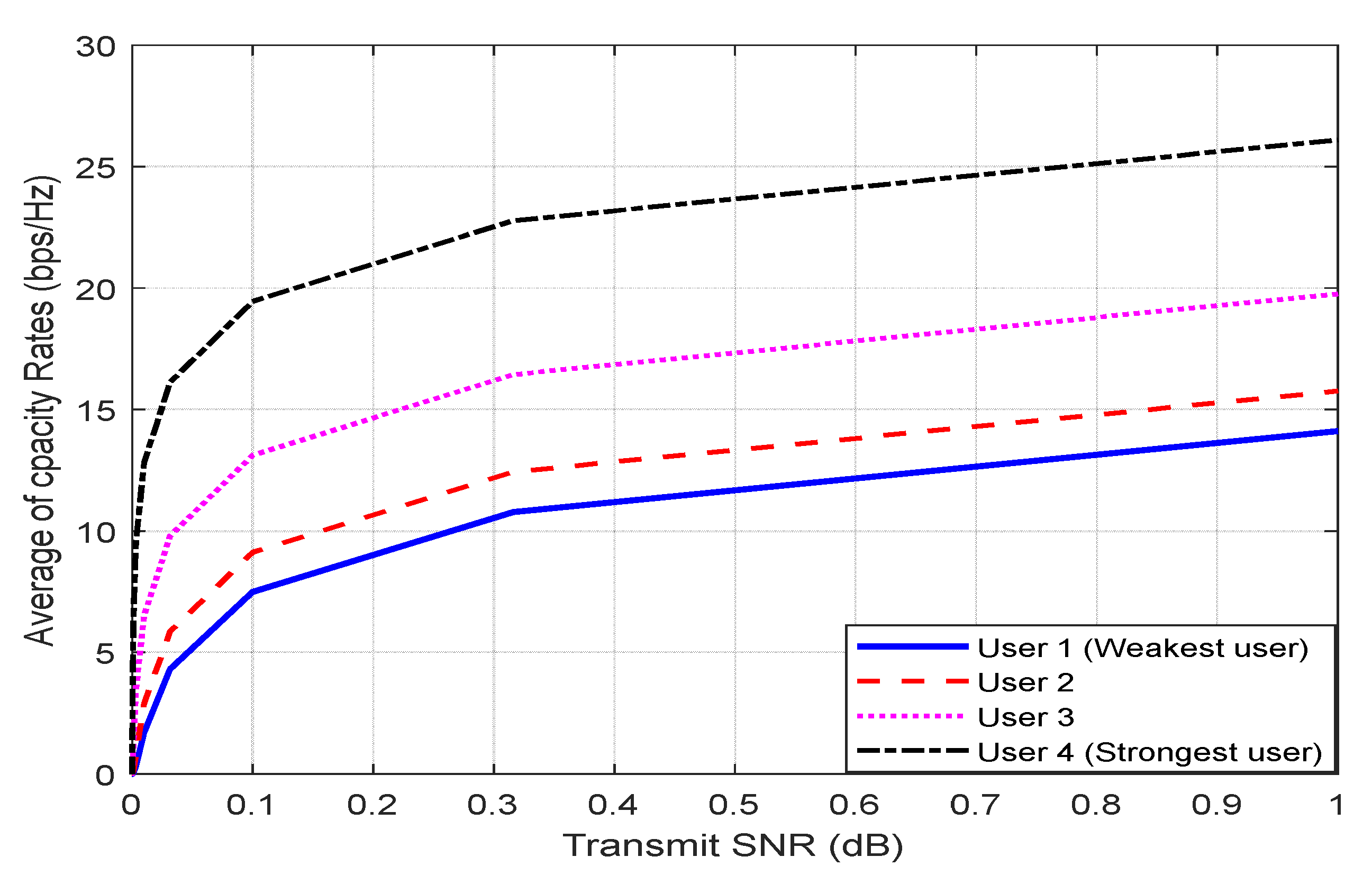
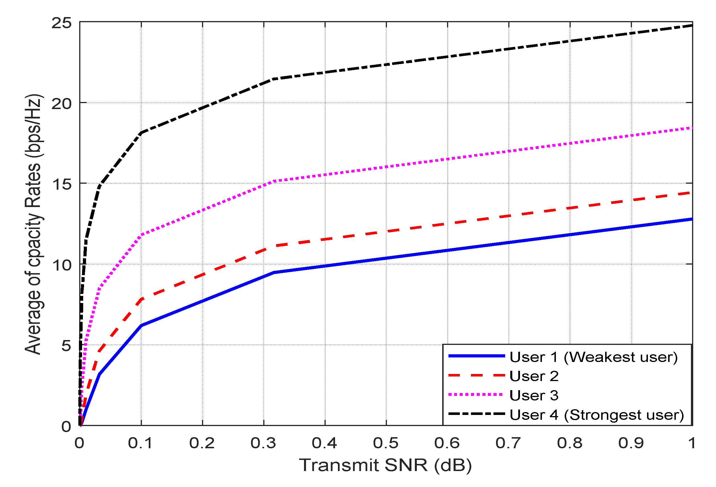
The average capacity rate performance for UL NOMA versus SNR at 80 MHz BW and 64 × 64 MIMO is obtained in Figure 13. The outcomes were achieved for four users 12.7881, 14.4423, 18.4489, and 24.7815, respectively. Figure 14 shows the average capacity rate performance versus SNR for UL NOMA at 200 MHz BW and 64 × 64 MIMO. The results show that the average capacity rate performance improves as the SNR increases. The average capacity rate performance for U4 is the best according to the data obtained for four users 14.1110, 15.7659, 19.7693, and 26.1040 at the SNR of 1 dB. Users’ performance has improved considerably.
The BW and average capacity rate have a positive relationship, with an increase in BW leading to an increase in average capacity rate. The average capacity rate increases dramatically when the system is enhanced using the MIMO scheme.
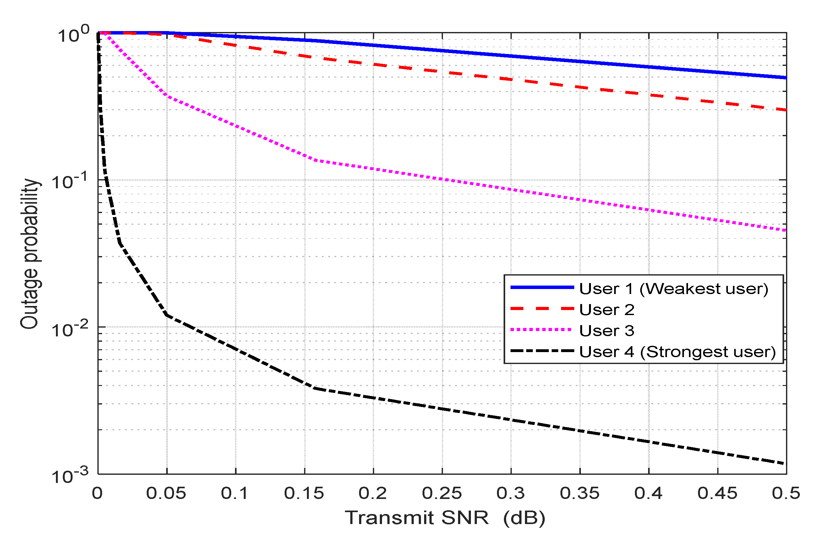
The UL NOMA of OP vs. SNR correlation is shown in Figure 15 at 80 MHz BW. When SNR is 0.17 dB, the results for U1, U2, U3, and U4 are 99.9 × 10⁻², 98.9 × 10⁻², 44.3 × 10⁻², and 15 × 10−3, respectively. Figure 16 depicts the UL NOMA of OP versus the SNR at 200 MHz BW. At an SNR of 0.17 dB, the results for U1, U2, U3, and U4 are 0.9989, 0.9715, 0.3709, and 0.0120, respectively. The findings show that as the SNR improves, the OP performance decreases. Results achieved have an improvement in average capacity rate and are superior to those of the best U2 users in [35].
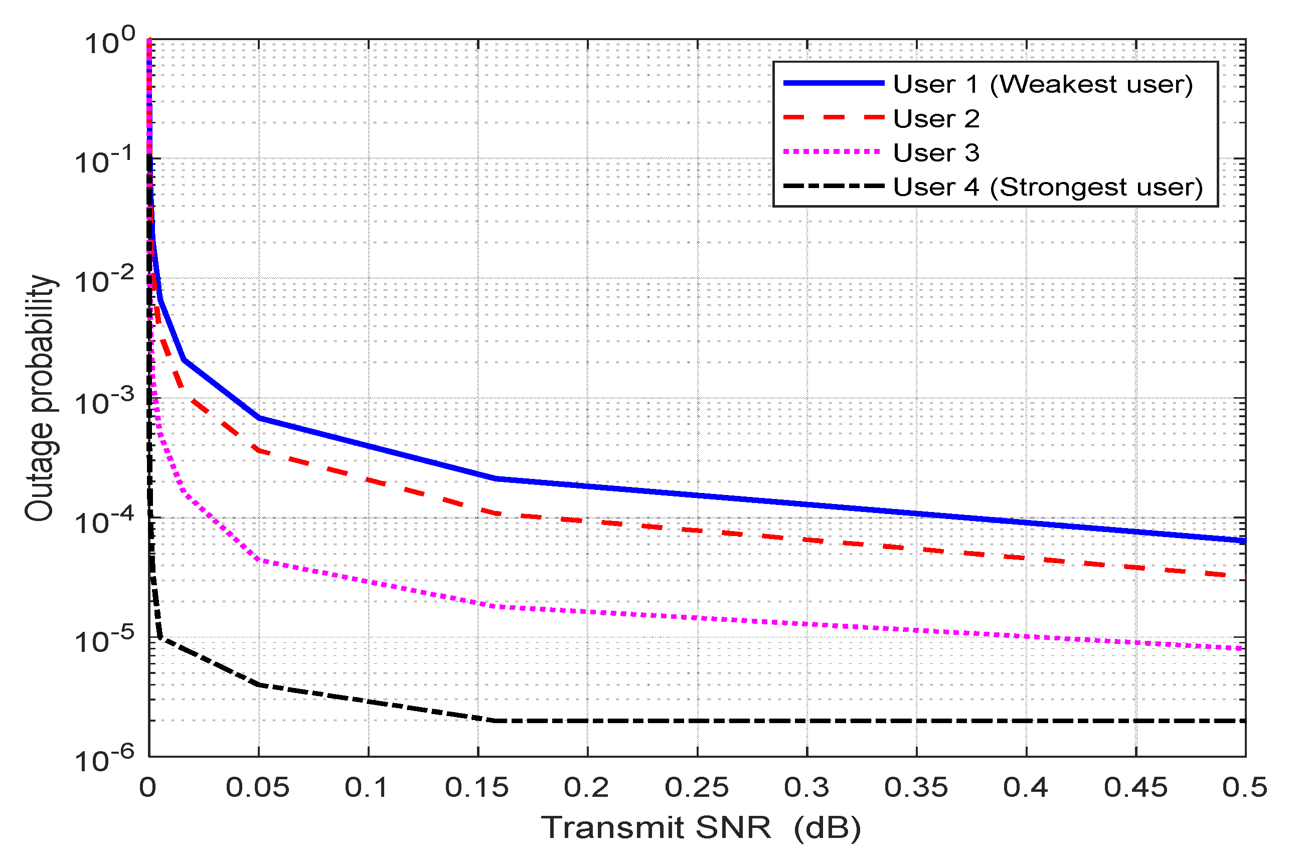
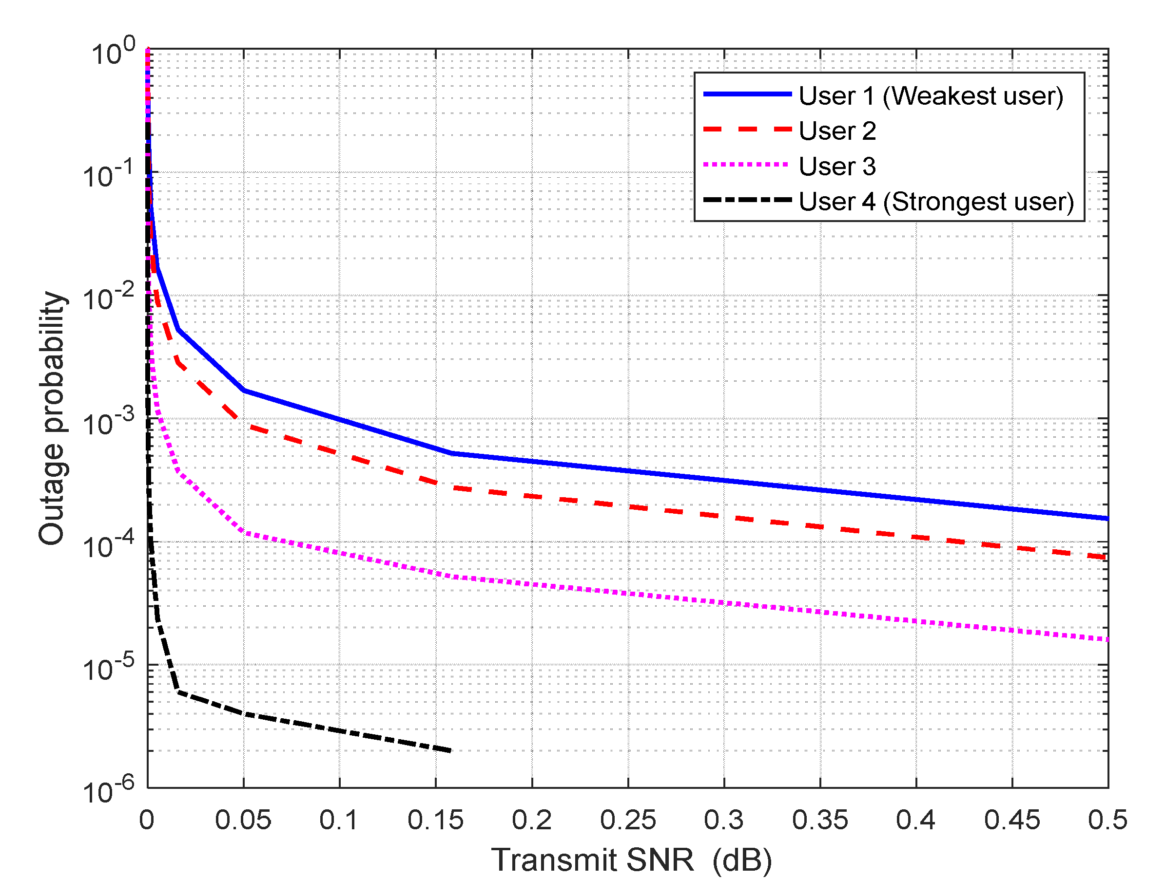
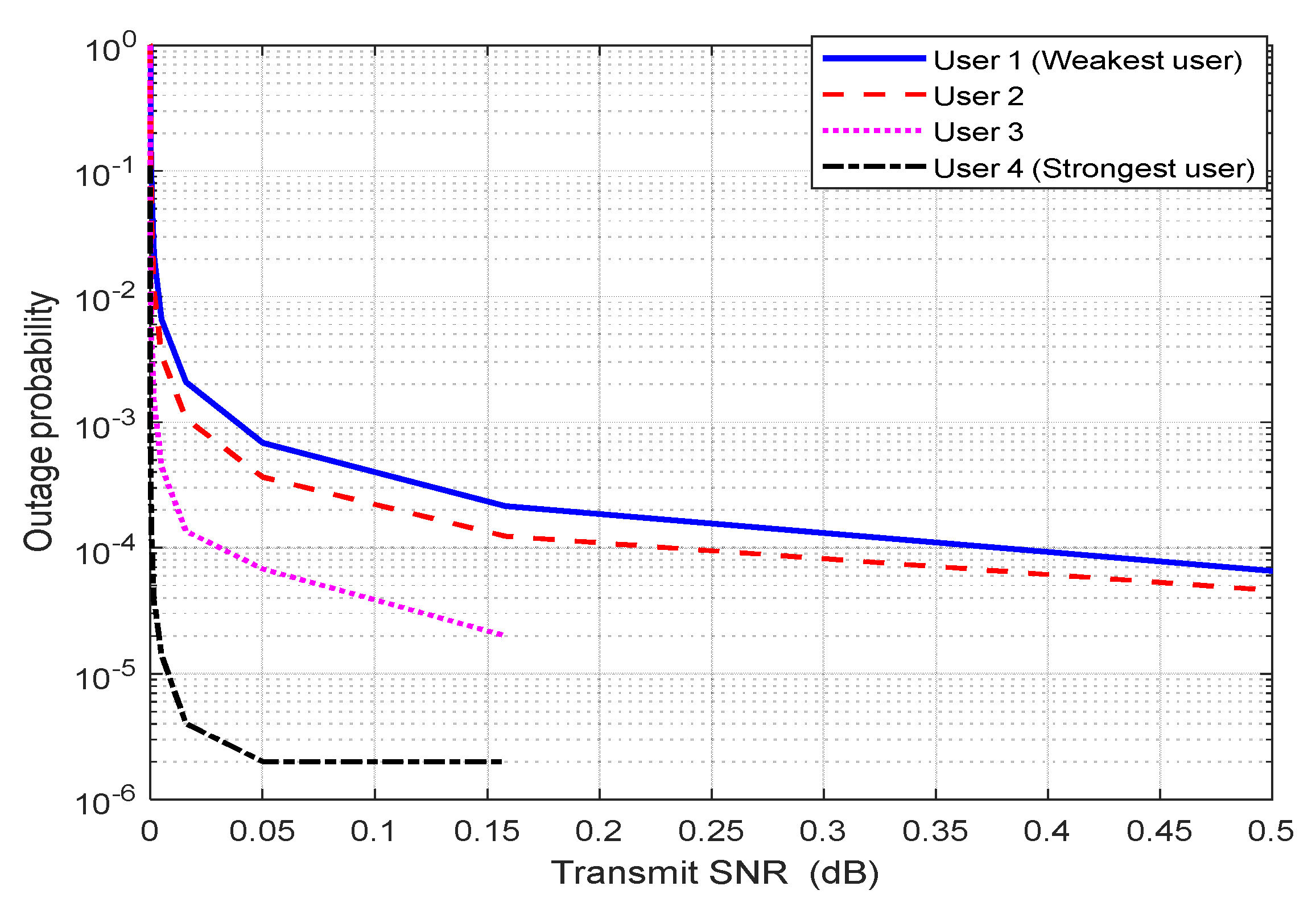
At 80 MHz BW with 64 × 64 MIMO, Figure 17 depicts the UL NOMA of OP vs. SNR. At an SNR of 0.17 dB, the outcomes for U1, U2, U3, and U4 are 0.0053, 0.0027, 0.0003, and 0.0000. At 200 MHz BW and 64 × 64 MIMO, Figure 18 depicts the UL NOMA of OP vs. the SNR. At an SNR of 0.17 dB, the results for U1, U2, U3, and U4 are 21 × 10−4, 10−4, 10−4, and 10−5. The data show that when the SNR increases, the performance of the OP decreases [39,40,41].
The BW and OP have an inverse connection, with an increase in BW resulting in a drop in OP. The OP drops dramatically when the system is optimized utilizing the MIMO technique. With an improvement rate of 10−1.9 in OP, the results are superior to those of the top U2 users in [38].
6. Conclusions and Future Work
This paper demonstrated the performance of DL and UL NOMA PD in a 5G network with and without 64 × 64 MIMO technologies. The BER and SE performance of DL NOMA was investigated and analyzed for various distances, power location coefficients, transmitted power, and BW, whereas the average capacity rate and OP performance of UL NOMA were examined for various distances, SNR, and BW. The DL NOMA system results showed that using 64 × 64 MIMO enhanced the performance of BER, and SE, and solved the near–far user’s problem, where the performance of all users becomes close to each other’s for different transmitted power, distance, and power location coefficients parameters when compared without MIMO DL NOMA performance. The results demonstrated that the 64 × 64 MIMO DL NOMA enhances the BER performance for the best user U4 from 10−1.7 to 10−5.2 at 80 MHz BW, and from 10−1.5 to 10−5 at 200 MHz BW at a transmitter power of 40 dBm. In contrast, the SE performance for the best user U4 is improved by 0.8% bps/Hz for 80 MHz BW and by 1.01% bps/Hz for 200 MHz BW at a transmitter power of 40 dBm. The UL NOMA systems results obtained using 64 × 64 MIMO enhanced the average capacity rate performance by 12 bps/Hz, reduced the OP by 0.0150 for 80 MHz BW at SNR of 1 dB, improved the average capacity rate performance by 12 bps/Hz, and decreased the OP by 0.0120 for 200 MHz BW at SNR of 0.17 dB for the best user U4. In general, an increase in BW increases BER and average capacity rate while decreasing SE and OP. MIMO significantly improves the performance of all users. In the future, it will be looked into how MIMO cooperative NOMA and cognitive radio work together.
Author Contributions
Conceptualization, M.H.; methodology, M.H. and M.S.; software, M.H.; validation, M.H., M.S. and K.H.; formal analysis, M.H., M.S. and K.H.; investigation, R.S. and R.A.; resources, R.S., M.A. and R.A.; data curation, R.S., M.A. and R.A.; writing—original draft preparation, M.H.; writing—review and editing, M.A., R.S. and R.A.; visualization, M.H. and K.H.; supervision, M.S.; project administration, M.S.; funding acquisition, M.A. All authors have read and agreed to the published version of the manuscript.
Funding
This research was supported by Princess Nourah bint Abdulrahman University Researchers Supporting Project Number (PNURSP2022R97), Princess Nourah bint Abdulrahman University, Riyadh, Saudi Arabia.
Institutional Review Board Statement
Not applicable.
Informed Consent Statement
Not applicable.
Data Availability Statement
Not applicable.
Acknowledgments
Princess Nourah bint Abdulrahman University Researchers Supporting Project Number (PNURSP2022R97), Princess Nourah bint Abdulrahman University, Riyadh, Saudi Arabia.
Conflicts of Interest
The authors declare no conflict of interest.
References
- Dai, L.; Wang, B.; Yuan, Y.; Han, S.; Chih-Lin, I.; Wang, Z. Non-orthogonal multiple access for 5G: Solutions, challenges, opportunities, and future research trends. IEEE Commun. Mag. 2015, 53, 74–81. [Google Scholar] [CrossRef]
- Timotheou, S.; Krikidis, I. Fairness for non-orthogonal multiple access in 5G systems. IEEE Signal Processing Lett. 2015, 22, 1647–1651. [Google Scholar] [CrossRef] [Green Version]
- Chen, Z.; Ding, Z.; Dai, X.; Zhang, R. An optimization perspective of the superiority of NOMA compared to conventional OMA. IEEE Trans. Signal Processing 2017, 65, 5191–5202. [Google Scholar] [CrossRef] [Green Version]
- Feng, D. Performance comparison on NOMA schemes in high speed scenario. In Proceedings of the 2019 IEEE 2nd International Conference on Electronics Technology (ICET), Chengdu, China, 10–13 May 2019; pp. 112–116. [Google Scholar]
- Bello, M.; Chorti, A.; Fijalkow, I.; Yu, W.; Musavian, L. Asymptotic performance analysis of NOMA uplink networks under statistical QoS delay constraints. IEEE Open J. Commun. Soc. 2020, 1, 1691–1706. [Google Scholar] [CrossRef]
- Maatouk, A.; Assaad, M.; Ephremides, A. Minimizing the age of information: NOMA or OMA? In Proceedings of the IEEE INFOCOM 2019-IEEE Conference on Computer Communications Workshops (INFOCOM WKSHPS), Paris, France, 29 April–2 May 2019; pp. 102–108. [Google Scholar]
- Wei, Z.; Yang, L.; Ng, D.W.K.; Yuan, J.; Hanzo, L. On the performance gain of NOMA over OMA in uplink communication systems. IEEE Trans. Commun. 2019, 68, 536–568. [Google Scholar] [CrossRef] [Green Version]
- Ding, Z.; Zhao, Z.; Peng, M.; Poor, H.V. On the spectral efficiency and security enhancements of NOMA assisted multicast-unicast streaming. IEEE Trans. Commun. 2017, 65, 3151–3163. [Google Scholar] [CrossRef]
- Hassan, M.; Singh, M.; Hamid, K. Survey on NOMA and Spectrum Sharing Techniques in 5G. In Proceedings of the 2021 IEEE International Conference on Smart Information Systems and Technologies (SIST), Nur-Sultan, Kazakhstan, 28–30 April 2021; pp. 1–4. [Google Scholar]
- Makki, B.; Chitti, K.; Behravan, A.; Alouini, M.-S. A survey of NOMA: Current status and open research challenges. IEEE Open J. Commun. Soc. 2020, 1, 179–189. [Google Scholar] [CrossRef] [Green Version]
- Shahab, M.B.; Johnson, S.J.; Shirvanimoghaddam, M.; Chafii, M.; Basar, E.; Dohler, M. Index modulation aided uplink NOMA for massive machine type communications. IEEE Wirel. Commun. Lett. 2020, 9, 2159–2162. [Google Scholar] [CrossRef]
- Cejudo, E.C.; Zhu, H.; Alluhaibi, O. On the power allocation and constellation selection in downlink NOMA. In Proceedings of the 2017 IEEE 86th Vehicular Technology Conference (VTC-Fall), Toronto, ON, Canada, 24–27 September 2017; pp. 1–5. [Google Scholar]
- Lei, L.; Yuan, D.; Ho, C.K.; Sun, S. Power and channel allocation for non-orthogonal multiple access in 5G systems: Tractability and computation. IEEE Trans. Wirel. Commun. 2016, 15, 8580–8594. [Google Scholar] [CrossRef] [Green Version]
- Chandrasekhar, R.; Navya, R.; Kumari, P.K.; Kausal, K.; Bharathi, V.; Singh, P. Performance evaluation of MIMO-NOMA for the next generation wireless communications. In Proceedings of the 2021 3rd International Conference on Signal Processing and Communication (ICPSC), Coimbatore, India, 13–14 May 2021; pp. 631–636. [Google Scholar]
- Saetan, W.; Thipchaksurat, S. Application of deep learning to energy-efficient power allocation scheme for 5G SC-NOMA system with imperfect SIC. In Proceedings of the 2019 16th International Conference on Electrical Engineering/Electronics, Computer, Telecommunications and Information Technology (ECTI-CON), Pattaya, Thailand, 10–13 July 2019; pp. 661–664. [Google Scholar]
- Tweed, D.; Le-Ngoc, T. Dynamic resource allocation for uplink MIMO NOMA VWN with imperfect SIC. In Proceedings of the 2018 IEEE International Conference on Communications (ICC), Kansas City, MO, USA, 20–24 May 2018; pp. 1–6. [Google Scholar]
- Krishnamoorthy, A.; Huang, M.; Schober, R. Precoder design and power allocation for downlink MIMO-NOMA via simultaneous triangularization. In Proceedings of the 2021 IEEE Wireless Communications and Networking Conference (WCNC), Nanjing, China, 29 March–1 April 2021; pp. 1–6. [Google Scholar]
- Hua, Y.; Wang, N.; Zhao, K. Simultaneous unknown input and state estimation for the linear system with a rank-deficient distribution matrix. Math. Probl. Eng. 2021, 2021, 6693690. [Google Scholar] [CrossRef]
- Sun, H.; Sun, J.; Zhao, K.; Wang, L.; Wang, K. Data-Driven ICA-Bi-LSTM-Combined Lithium Battery SOH Estimation. Math. Probl. Eng. 2022, 2022, 9645892. [Google Scholar] [CrossRef]
- Rehman, B.U.; Babar, M.I.; Ahmad, A.W.; Alhumyani, H.; Abdel Azim, G.; Saeed, R.A.; Abdel Khalek, S. Joint power control and user grouping for uplink power domain non-orthogonal multiple access. Int. J. Distrib. Sens. Netw. 2021, 17, 15501477211057443. [Google Scholar] [CrossRef]
- Shieh, S.-L.; Lin, C.-H.; Huang, Y.-C.; Wang, C.-L. On gray labeling for downlink non-orthogonal multiple access without SIC. IEEE Commun. Lett. 2016, 20, 1721–1724. [Google Scholar] [CrossRef]
- Al Rabee, F.; Davaslioglu, K.; Gitlin, R. The optimum received power levels of uplink non-orthogonal multiple access (NOMA) signals. In Proceedings of the 2017 IEEE 18th Wireless and Microwave Technology Conference (WAMICON), Cocoa Beach, FL, USA, 24–25 April 2017; pp. 1–4. [Google Scholar]
- Tweed, D.; Derakhshani, M.; Parsaeefard, S.; Le-Ngoc, T. Outage-constrained resource allocation in uplink NOMA for critical applications. IEEE Access 2017, 5, 27636–27648. [Google Scholar] [CrossRef]
- Ding, Z.; Lei, X.; Karagiannidis, G.K.; Schober, R.; Yuan, J.; Bhargava, V.K. A survey on non-orthogonal multiple access for 5G networks: Research challenges and future trends. IEEE J. Sel. Areas Commun. 2017, 35, 2181–2195. [Google Scholar] [CrossRef] [Green Version]
- Moriyama, M.; Kurosawa, A.; Matsuda, T.; Matsumura, T. A Study of Parallel Interference Cancellation Combined with Successive Interference Cancellation for UL-NOMA Systems. In Proceedings of the 2021 24th International Symposium on Wireless Personal Multimedia Communications (WPMC), Okayama, Japan, 14–16 December 2021; pp. 1–6. [Google Scholar]
- Hassan, M.B.; Ali, E.S.; Saeed, R.A. Ultra-Massive MIMO in THz Communications: Concepts, Challenges and Applications. In Next Generation Wireless Terahertz Communication Networks, 1st ed.; CRC Press: Boca Raton, FL, USA, 2021; Chapter 10; pp. 267–297. [Google Scholar]
- Budhiraja, I.; Kumar, N.; Tyagi, S.; Tanwar, S.; Han, Z.; Piran, M.J.; Suh, D.Y. A systematic review on NOMA variants for 5G and beyond. IEEE Access 2021, 9, 85573–85644. [Google Scholar] [CrossRef]
- Celik, A.; Al-Qahtani, F.S.; Radaydeh, R.M.; Alouini, M.-S. Cluster formation and joint power-bandwidth allocation for imperfect NOMA in DL-HetNets. In Proceedings of the GLOBECOM 2017-2017 IEEE Global Communications Conference, Singapore, 4–8 December 2017; pp. 1–6. [Google Scholar]
- Zeng, J.; Lv, T.; Liu, R.P.; Su, X.; Peng, M.; Wang, C.; Mei, J. Investigation on evolving single-carrier NOMA into multi-carrier NOMA in 5G. IEEE Access 2018, 6, 48268–48288. [Google Scholar] [CrossRef]
- Islam, S.R.; Avazov, N.; Dobre, O.A.; Kwak, K.-S. Power-domain non-orthogonal multiple access (NOMA) in 5G systems: Potentials and challenges. IEEE Commun. Surv. Tutor. 2016, 19, 721–742. [Google Scholar] [CrossRef] [Green Version]
- Alsaqour, R.; Ali, E.S.; Mokhtar, R.A.; Saeed, R.A.; Alhumyani, H.; Abdelhaq, M. Efficient Energy Mechanism in Heterogeneous WSNs for Underground Mining Monitoring Applications. IEEE Access 2022, 10, 72907–72924. [Google Scholar] [CrossRef]
- Aldababsa, M.; Göztepe, C.; Kurt, G.K.; Kucur, O. Bit error rate for NOMA network. IEEE Commun. Lett. 2020, 24, 1188–1191. [Google Scholar] [CrossRef]
- Al-Abbasi, Z.Q.; Khamis, M.A. Spectral efficiency (SE) enhancement of NOMA system through iterative power assignment. Wirel. Netw. 2021, 27, 1309–1317. [Google Scholar] [CrossRef]
- Li, S.; Wei, Z.; Yuan, W.; Yuan, J.; Bai, B.; Ng, D.W.K. On the achievable rates of uplink NOMA with asynchronized transmission. In Proceedings of the 2021 IEEE Wireless Communications and Networking Conference (WCNC), Nanjing, China, 29 March–1 April 2021; pp. 1–7. [Google Scholar]
- Choi, J. Minimum power multicast beamforming with superposition coding for multiresolution broadcast and application to NOMA systems. IEEE Trans. Commun. 2015, 63, 791–800. [Google Scholar] [CrossRef]
- Liu, F.; Petrova, M. Proportional fair scheduling for downlink single-carrier NOMA systems. In Proceedings of the GLOBECOM 2017-2017 IEEE Global Communications Conference, Singapore, 4–8 December 2017; pp. 1–7. [Google Scholar]
- Saeed, R.A.; Abbas, E.B. Performance evaluation of MIMO FSO communication with gamma-gamma turbulence channel using diversity techniques. In Proceedings of the 2018 International Conference on Computer, Control, Electrical, and Electronics Engineering (ICCCEEE), Khartoum, Sudan, 12–14 August 2018; pp. 1–5. [Google Scholar]
- Shen, D.; Wei, C.; Zhou, X.; Wang, L.; Xu, C. Photon Counting Based Iterative Quantum Non-Orthogonal Multiple Access with Spatial Coupling. In Proceedings of the 2018 IEEE Global Communications Conference (GLOBECOM), Abu Dhabi, United Arab Emirates, 9–13 December 2018; pp. 1–6. [Google Scholar]
- Mokhtar, R.A.; Saeed, R.A.; Alhumyani, H. Cooperative Fusion Architecture-based Distributed Spectrum Sensing Under Rayleigh Fading Channel. Wirel. Pers. Commun. 2022, 124, 839–865. [Google Scholar] [CrossRef]
- Lo, S.-H.; Chen, Y.-F. Subcarrier Allocation for Rate Maximization in Multiuser OFDM NOMA Systems on Downlink Beamforming. In Proceedings of the 2020 6th International Conference on Applied System Innovation (ICASI), Taitung, Taiwan, 5–8 November 2020; pp. 56–61. [Google Scholar]
- Abdelrahman, Y.T.; Saeed, R.A.; El-Tahir, A. Multiple Physical Layer Pipes performance for DVB-T2. In Proceedings of the 2017 International Conference on Communication, Control, Computing and Electronics Engineering (ICCCCEE), Khartoum, Sudan, 16–18 January 2017; pp. 1–7. [Google Scholar]
- Sedaghat, M.A.; Müller, R.R. On user pairing in uplink NOMA. IEEE Trans. Wirel. Commun. 2018, 17, 3474–3486. [Google Scholar] [CrossRef]
- Agarwal, A.; Chaurasiya, R.; Rai, S.; Jagannatham, A.K. Outage probability analysis for NOMA downlink and uplink communication systems with generalized fading channels. IEEE Access 2020, 8, 220461–220481. [Google Scholar] [CrossRef]
- Mukhtar, A.M.; Saeed, R.A.; Mokhtar, R.A.; Ali, E.S.; Alhumyani, H. Performance Evaluation of Downlink Coordinated Multipoint Joint Transmission under Heavy IoT Traffic Load. Wirel. Commun. Mob. Comput. 2022, 2022, 6837780. [Google Scholar] [CrossRef]
- Do, D.-T.; Nguyen, T.-T.T.; Nguyen, T.N.; Li, X.; Voznak, M. Uplink and downlink NOMA transmission using full-duplex UAV. IEEE Access 2020, 8, 164347–164364. [Google Scholar] [CrossRef]
- Krishnamoorthy, A.; Schober, R. Uplink and downlink MIMO-NOMA with simultaneous triangularization. IEEE Trans. Wirel. Commun. 2021, 20, 3381–3396. [Google Scholar] [CrossRef]
- Do, D.-T.; Nguyen, T.-L.; Ekin, S.; Kaleem, Z.; Voznak, M. Joint user grouping and decoding order in uplink/downlink MISO/SIMO-NOMA. IEEE Access 2020, 8, 143632–143643. [Google Scholar] [CrossRef]
- Elbamby, M.S.; Bennis, M.; Saad, W.; Debbah, M.; Latva-Aho, M. Resource optimization and power allocation in in-band full duplex-enabled non-orthogonal multiple access networks. IEEE J. Sel. Areas Commun. 2017, 35, 2860–2873. [Google Scholar] [CrossRef]
- Elfatih, N.M.; Hasan, M.K.; Kamal, Z.; Gupta, D.; Saeed, R.A.; Ali, E.S.; Hosain, M.S. Internet of vehicle’s resource management in 5G networks using AI technologies: Current status and trends. IET Commun. 2022, 16, 400–420. [Google Scholar] [CrossRef]
Figure 1.
Illustrates the wireless network consisting of 4 users 64 × 64 MIMO-DL-NOMA (power domain).
Figure 1.
Illustrates the wireless network consisting of 4 users 64 × 64 MIMO-DL-NOMA (power domain).

Figure 2.
Illustrates the wireless network consisting of 4 users 64 × 64 MIMO-UL-NOMA (power domain).
Figure 2.
Illustrates the wireless network consisting of 4 users 64 × 64 MIMO-UL-NOMA (power domain).

Figure 3.
BER vs. transmit power for four users with varying distances and power coefficients, for DL NOMA at BW (80 MHz).
Figure 3.
BER vs. transmit power for four users with varying distances and power coefficients, for DL NOMA at BW (80 MHz).

Figure 4.
BER against transmitting power for four users with varying distances and power coefficients, for DL NOMA at BW (200 MHz).
Figure 4.
BER against transmitting power for four users with varying distances and power coefficients, for DL NOMA at BW (200 MHz).

Figure 5.
BER vs. transmitting power for four users with varying distances and power coefficients, for DL NOMA at BW (80 MHz with 64 × 64 MIMO for DL NOMA.
Figure 5.
BER vs. transmitting power for four users with varying distances and power coefficients, for DL NOMA at BW (80 MHz with 64 × 64 MIMO for DL NOMA.

Figure 6.
BER against transmitting power for four users with varying distances and power coefficients for DL NOMA at BW 200 MHz with 64 × 64 MIMO for DL NOMA.
Figure 6.
BER against transmitting power for four users with varying distances and power coefficients for DL NOMA at BW 200 MHz with 64 × 64 MIMO for DL NOMA.

Figure 7.
SE vs. transmit power for four users with varying distances, with power coefficients and BW 80 MHz for DL NOMA.
Figure 7.
SE vs. transmit power for four users with varying distances, with power coefficients and BW 80 MHz for DL NOMA.

Figure 8.
SE against transmitting power for four users with varying distances, with power coefficients and BW 200 MHz for DL NOMA.
Figure 8.
SE against transmitting power for four users with varying distances, with power coefficients and BW 200 MHz for DL NOMA.

Figure 9.
SE vs. transmitting power for four users with varying distances, with power coefficients, with the 64 × 64 MIMO and BW 80 MHz for DL NOMA.
Figure 9.
SE vs. transmitting power for four users with varying distances, with power coefficients, with the 64 × 64 MIMO and BW 80 MHz for DL NOMA.

Figure 10.
SE against transmitting power for four users with varying distances, with power coefficients with the 64 × 64 MIMO and BW 200 MHz for DL NOMA.
Figure 10.
SE against transmitting power for four users with varying distances, with power coefficients with the 64 × 64 MIMO and BW 200 MHz for DL NOMA.

Figure 11.
Average capacity rate vs. SNR for four users with varying distances and BW 80 MHz for UL NOMA.
Figure 11.
Average capacity rate vs. SNR for four users with varying distances and BW 80 MHz for UL NOMA.

Figure 12.
Average capacity rate against SNR for four users with varying distances and BW 200 MHz for UL NOMA.
Figure 12.
Average capacity rate against SNR for four users with varying distances and BW 200 MHz for UL NOMA.

Figure 13.
Average capacity rate vs. SNR for four users with varying distances, with 64 × 64 MIMO and BW 80 MHz for UL NOMA.
Figure 13.
Average capacity rate vs. SNR for four users with varying distances, with 64 × 64 MIMO and BW 80 MHz for UL NOMA.

Figure 14.
Average capacity rate against SNR for four users with varying distances, with 64 × 64 MIMO and BW 200 MHz for UL NOMA.
Figure 14.
Average capacity rate against SNR for four users with varying distances, with 64 × 64 MIMO and BW 200 MHz for UL NOMA.

Figure 15.
OP vs. SNR for four users with varying distances and BW 80 MHz for UL NOMA.

Figure 16.
OP against SNR for four users with varying distances and BW 200 MHz for UL NOMA.

Figure 17.
OP vs. SNR for four users with varying distances, with 64 × 64 MIMO and BW 80 MHz for UL NOMA.
Figure 17.
OP vs. SNR for four users with varying distances, with 64 × 64 MIMO and BW 80 MHz for UL NOMA.

Figure 18.
OP against SNR for four users with varying distances, with 64 × 64 MIMO and BW 200 MHz for UL NOMA.
Figure 18.
OP against SNR for four users with varying distances, with 64 × 64 MIMO and BW 200 MHz for UL NOMA.


Table 1.
Simulator parameters for the DL scenario.
| No. | Parameters | Values | |
|---|---|---|---|
| 1. | Number of users | 4 users | |
| 2. | Transmit power | 0 to 40 dBm | |
| 3. | Bandwidth | BW 1 | 80 MHz |
| BW 2 | 200 MHz | ||
| 4. | Distances | User 1 | 800 m |
| User 2 | 600 m | ||
| User 3 | 300 m | ||
| User 4 | 100 m | ||
| 5. | Power coefficients | User 1 | 0.75 |
| User 2 | 0.188 | ||
| User 3 | 0.047 | ||
| User 4 | 0.011 | ||
| 6. | Path loss exponent | 4 | |
| 7. | MIMO | 64 × 64 | |
| 8. | Modulation | QPSK | |
Table 2.
Simulator parameters for the UL scenario.
| No. | Parameters | Values | |
|---|---|---|---|
| 1. | Number of users | 4 users | |
| 2. | Transmit power | −30 to 30 dBm | |
| 3. | Bandwidth | BW1 | 80 MHz |
| BW2 | 200 MHz | ||
| 4. | Distances | User1 | 800 m |
| User 2 | 600 m | ||
| User 3 | 300 m | ||
| User 4 | 100 m | ||
| 6. | Path loss exponent | 4 | |
| 7. | MIMO | 64 × 64 | |
Publisher’s Note: MDPI stays neutral with regard to jurisdictional claims in published maps and institutional affiliations. |
© 2022 by the authors. Licensee MDPI, Basel, Switzerland. This article is an open access article distributed under the terms and conditions of the Creative Commons Attribution (CC BY) license (https://creativecommons.org/licenses/by/4.0/).
Share and Cite
MDPI and ACS Style
Hassan, M.; Singh, M.; Hamid, K.; Saeed, R.; Abdelhaq, M.; Alsaqour, R. Modeling of NOMA-MIMO-Based Power Domain for 5G Network under Selective Rayleigh Fading Channels. Energies 2022, 15, 5668. https://doi.org/10.3390/en15155668
AMA Style
Hassan M, Singh M, Hamid K, Saeed R, Abdelhaq M, Alsaqour R. Modeling of NOMA-MIMO-Based Power Domain for 5G Network under Selective Rayleigh Fading Channels. Energies. 2022; 15(15):5668. https://doi.org/10.3390/en15155668
Chicago/Turabian StyleHassan, Mohamed, Manwinder Singh, Khalid Hamid, Rashid Saeed, Maha Abdelhaq, and Raed Alsaqour. 2022. "Modeling of NOMA-MIMO-Based Power Domain for 5G Network under Selective Rayleigh Fading Channels" Energies 15, no. 15: 5668. https://doi.org/10.3390/en15155668
Note that from the first issue of 2016, this journal uses article numbers instead of page numbers. See further details here.