
A Study on the Adaptability of Nonhydrocarbon Gas-Assisted Steam Flooding to the Development of Heavy Oil Reservoirs

1
Oil Production Technology Research Institute, Petro China Xinjiang Oilfield Company, Karamay 834000, China
2
Heavy Oil Development Company, PetroChina Xinjiang Oilfield Company, Karamay 834000, China
3
School of Petroleum Engineering, China University of Petroleum (East China), Qingdao 266580, China
*
Author to whom correspondence should be addressed.
Energies 2022, 15(13), 4805; https://doi.org/10.3390/en15134805
Submission received: 30 May 2022
/
Revised: 20 June 2022
/
Accepted: 24 June 2022
/
Published: 30 June 2022
(This article belongs to the Special Issue Advances in Unconventional Oil and Gas)
Abstract
:In view of the serious heat loss in the process of steam injection for heavy oil recovery, nonhydrocarbon gas combined with steam has attracted much attention in recent years to realize the efficient development of heavy oil. Due to the wide variety of nonhydrocarbon gases, their performance in pressurization, dissolution, viscosity reduction, and heat loss decrease is changeable. In this paper, four groups of one-dimensional physical simulation experiments on different nonhydrocarbon gas-assisted steam flooding methods were carried out, and the effect on oil displacement characteristics under high temperature and pressure conditions was studied. Moreover, the differences in N2, CO2, and flue gas in energy supplementation, heat transfer, and oil recovery efficiency were also analyzed. The results showed that the three nonhydrocarbon gas-assisted steam flooding methods could significantly improve the oil displacement efficiency, which was specifically embodied as a faster oil production rate and longer production period. Compared with pure steam flooding, the recovery was increased by 12.13%, 16.71% and 13.01%, respectively. The effects of N2 in energy supplementation and heat transfer reinforcement were the greatest among the three nonhydrocarbon gases, followed by those of flue gas, and the CO2 effects were the worst. The temperature at the end of the sandpack model increased by 14.3 °C, 8.8 °C and 13.1 °C, respectively. In addition, CO2-assisted steam flooding had a prominent oil recovery effect, and the oil content of the sands in the front and middle of the model was significantly lower than that of other displacement methods. Most importantly, combined with the analysis of the remaining oil in the oil sands after displacement, we explained the contrasting contradictions of the three non-hydrocarbon gases in terms of recovery and energy supply/heat transfer, and further confirmed the gas properties and reservoir adaptability of the three non-hydrocarbon gases. The results may provide a theoretical basis for the selection of nonhydrocarbon gases for heavy oil reservoirs with different production requirements.
1. Introduction
With the development of conventional oil and gas resources entering the middle and late stages, many tricky problems have arisen at the sites, such as the high moisture content of the export liquid and depletion of natural energy in the formation, inducing higher development difficulty and reducing economic benefits at the same time. However, the demand for energy is increasing daily, and conventional oil resources obviously cannot meet the requirements of the current fast-developing industry. To ensure national energy security and the sustainable development of society, it is urgent to intensify the exploration of unconventional oil and gas resources and new energy. As one of the representatives, heavy oil is widely distributed in the world and has abundant reserves, accounting for more than 70% of the world’s total oil reserves, and approximately 17% is recoverable, showing promising value and prospects for development [1,2]. Compared with conventional oil, the most notable features of heavy oil are high viscosity, high specific gravity, and the existence of many heavy components, such as sulfur, heavy metals, and asphaltenes, giving rise to its large flowing resistance in the formation, so the recoverable reserves through water flooding are extremely low, which is the fundamental reason for its limited production. Heavy oil has evident thermal expansion and temperature sensitivity; that is, when the temperature increases, the viscosity decreases, and the fluidity increases [3,4]. Therefore, thermal technologies have become an effective means of heavy oil development. Multiple conventional thermal methods of enhancing oil recovery, such as in situ combustion, hot water flooding and steam injection, which include steam huff and puff [5,6,7], steam flooding [8,9] and chemical assisted steam flooding [10], are being used by the oil and gas industry [11]. In addition, new measures, such as electromagnetic heating [12,13,14] and catalytic modification [15], also have significant potential exploration value.
Nevertheless, almost all thermal measures exhibit certain faults in technological aspects. In the process of steam flooding, the injected steam is prone to gas channeling along the high-permeability layer formed by the heterogeneity of the formation. The water breakthrough time of the oil well is greatly shortened, and the heat cannot comprehensively spread to the vast formation, so the ultimate recovery is located at a relatively low degree. On the other hand, when continuously injecting steam into the rock-oil-water system, a phase change (from liquid to steam phase) usually occurs, ultimately inducing unfavorable wettability and directly affecting the extent of heavy oil recovery [16,17,18]. Therefore, a series of measures to improve heat utilization, such as suppressing steam channeling, expanding the scope of heat spread, and reducing heat loss during the process, have been key to solving this problem. Flue gas, as a kind of non-condensable gas, is mainly formed in the process of producing steam. Because of its low thermal conductivity, it is widely used in thermal recovery processes to achieve the efficient development of crude oil and simultaneously reduce carbon emissions. Zhoujie Wang et al. [19] conducted steam condensation heat transfer experiments with the addition of flue gas and steam flooding experiments in a one-dimensional sandpack model. They believed that the flue gas can inhibit the condensation and heat release of steam in the front and middle parts of the reservoir and hinder the formation of condensing droplets, thereby promoting the expansion of the steam chamber into the deep reservoir. The adsorption and retention of nanoparticles in the reservoir can result in a significant plugging effect, forcing the direction of liquid flow to change and increasing the sweep coefficient. Osamah A. and Abdullah F. [20] synergized the recovery mechanisms of both EOR agents by injecting a hot hydrophilic nanofluid (HNF) slug, followed by superheated steam (SHS) in a second slug. The thermophysical properties of hydrophilic nanoparticles improve the thermal performance of SHS injection and increase oil mobility, which can substantially reduce steam consumption by up to 50% and reduce the costs of producing steam while also improving oil recovery through the utilization of nanotechnology. When passing through a narrow rock pore throat, the foam expands and deforms, generating additional flow resistance. With the continuous accumulation of foam, the resistance effect becomes increasingly obvious. Moreover, foam has the characteristics of blocking water but not oil and is often called an intelligent fluid. Yongqing Bai et al. [21] foamed a physically crosslinked clayey hydrogel Bent/PAM with low thermal conductance, high thermal stability and good mobility, which was synthesized by a one-pot process, enabling remarkable blockage of steam channeling. Zhanxi Pang et al. [22] selected a kind of foaming agent for thermal foam flooding and carried out many displacements in a sandpack, and the results showed that foam can effectively increase the displacement efficiency of steam flooding from 43.30% to 81.24% and that thermal foams can effectively improve the injection profile to restrain steam injection from gravity override and steam channeling in reservoirs. Changfeng Xi et al. [23] conducted 3D physical modeling experiments of steam flooding, CO2-foam-assisted steam flooding, and CO2-assisted steam flooding under different perforation conditions. The experimental results show that after the adjustment of perforation holes in the later stage of CO2-assisted steam flooding, the steam chamber in the middle and lower part of the water injection well expand laterally, and the production and development mode of gravity drainage is formed in the top chamber of the production well.
In this paper, from the perspective of increasing the heat transfer range of steam and promoting the expansion of the steam chamber to the deep reservoir, the effects of different types of gases on the oil production rate, temperature field change, displacement pressure, etc., were researched based on a one-dimensional steam flooding experiment assisted by nonhydrocarbon gas. The oil displacement characteristics and the distribution of the remaining oil after displacement were also analyzed, yielding a certain guiding significance for the development of enhanced heavy oil recovery by injecting gas/steam.
2. Experimental Section
2.1. Materials
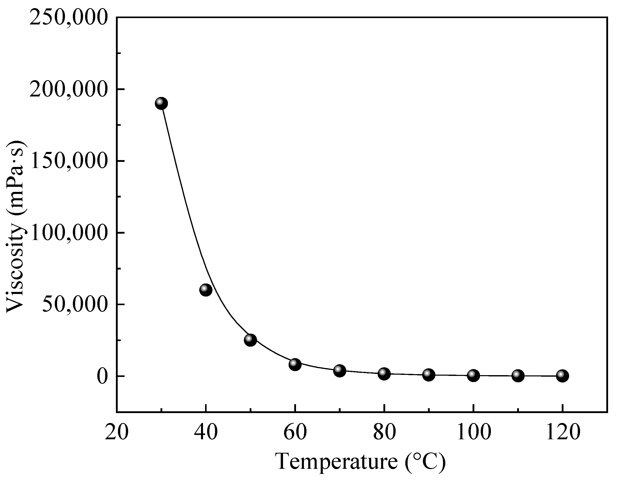
Removal of brine and gases from crude oil samples. The crude oil used in the experiment came from China’s Shengli Oilfield. The viscosity of the crude oil was tested by a rheometer (Model MCR 302, Anton Paar, Austria). The relationship between viscosity and temperature is shown in Figure 1. The flue gas used in the experiment was a 1:4 mixture of CO2 and N2, which was similar to actual flue gas produced by steam generators in oil fields. The purity of CO2 and N2 were both 99.9 mol%, provided by China Tianyuan Company. Two types of silica sands were used to fill the sandbags: 80 mesh and 120 mesh, respectively. The water used in the laboratory to generate steam was distilled water. The parameters of the sand bag used in the oil displacement experiment are shown in Table 1. The physical properties of the sand bag were the same, which was consistent with actual field conditions.
2.2. Apparatus
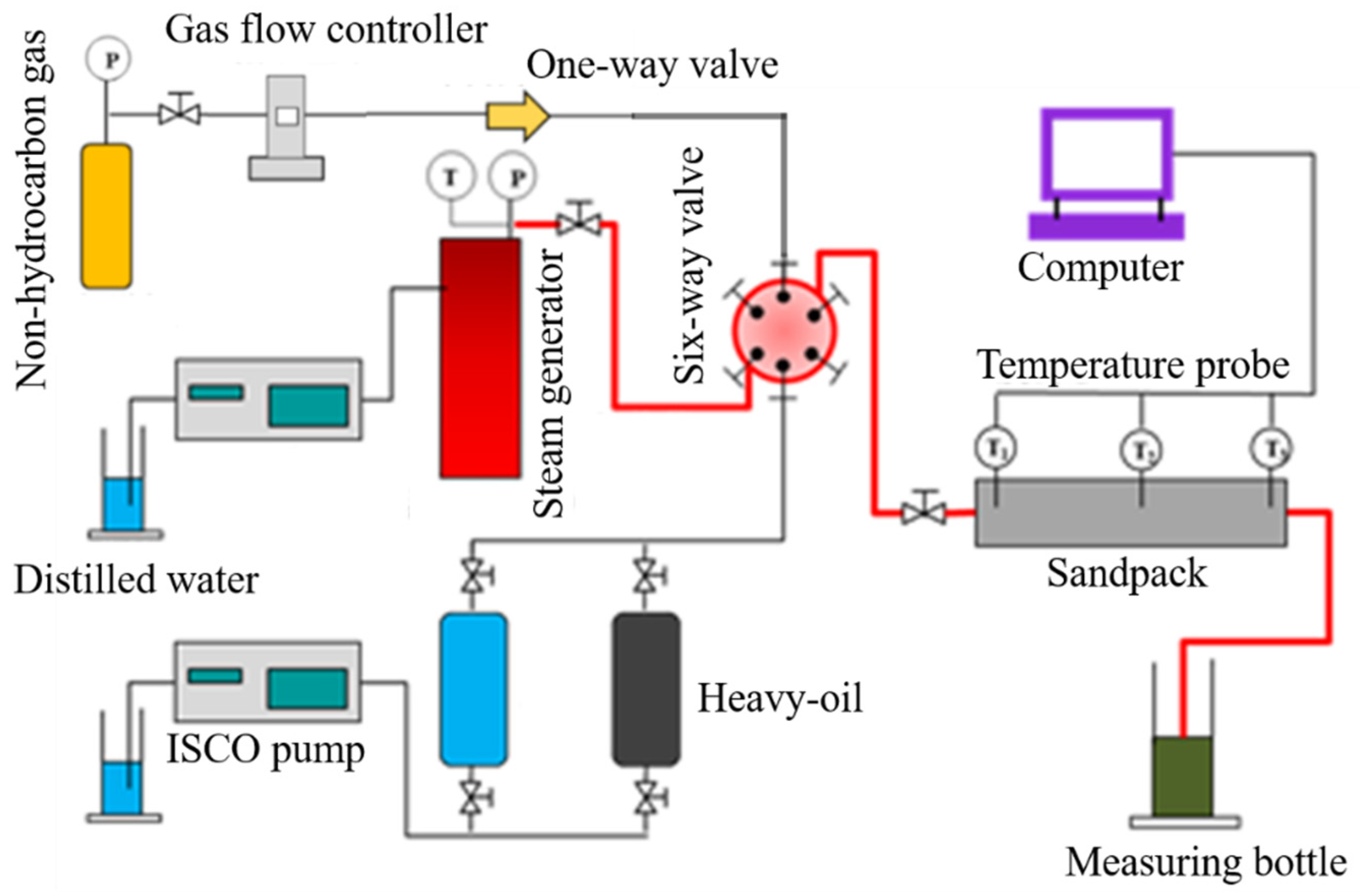
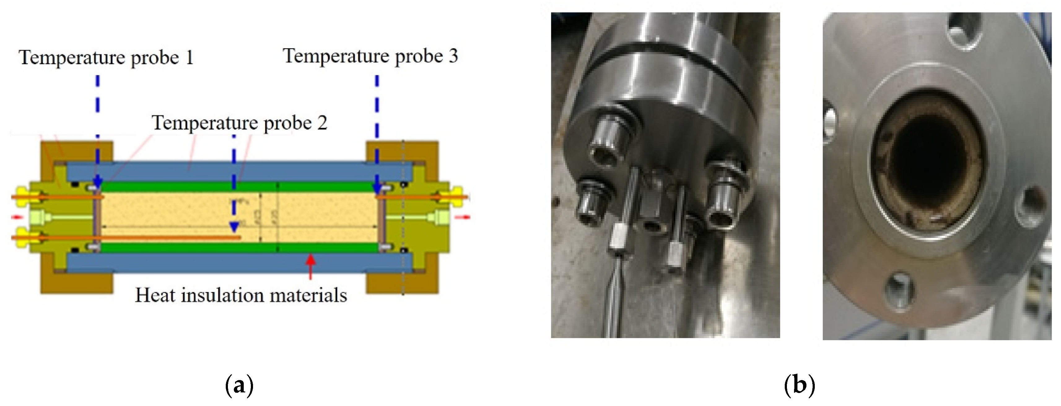
The flow chart of the nonhydrocarbon gas-assisted steam flooding experiment is shown in Figure 2 and the involved experimental devices are listed in Table 2. A specific flow of flue gas was injected into the experimental model through a gas flow controller. Distilled water pressurized by a high-precision syringe pump was heated into steam by a steam generator. Water or heavy oil was injected from the intermediate vessel into the sand bag with three temperature test points. The temperature was measured by thermocouples. The schematic diagram and real picture of the sandpack model are shown in Figure 3.
2.3. Experimental Procedures
(1) Fill the sandpack with sand of different diameters, and then test the air tightness of the sandpack.
(2) Measure the dry weight of the sandpack. Then, test the wet weight of the sandpack saturated with salt water. The porosity is calculated from the weight difference, and the permeability is calculated from the Darcy equation.
(3) Place the sandpack in a 100 °C oven for 2 h until the temperature of the sandpack stabilizes. Then, crude oil is injected into the sandpack at a flow rate of 0.5 mL/min to achieve oil saturation.
(4) The steam generator is pre-heated at a temperature of 250 °C. When the temperature of the sandpack and the steam generator stabilize, steam or steam with flue gas is injected into the sandpack according to the designed experimental parameters. The steam injection flow rate is set to the equivalent of condensate water.
(5) During the experiment, the temperature of each temperature measurement point in the sandpack is monitored and recorded in real time, and the water production and crude oil production are recorded.
(6) When the temperature of the sandpack is stable and the proportion of water in the produced fluid reaches 98%, the oil displacement experiment is stopped.
(7) The oil sand samples located in different positions of the model after the end of the displacement are selected to analyze the distribution of the remaining oil and evaluate the oil displacement effect of different displacement methods. The injection parameters of various displacement experiments are shown in Table 3.
3. Results and Discussion
3.1. Variation in the Oil Displacement Parameters
In the experiments, temperature changes at three locations within the sandpack were used to determine the heat transfer performance of steam flow in porous media. The temperature changes of the three thermocouples in the sandpack under different injection parameters were obtained. After the temperature of the sandpack was stable in the experiment, the data of each temperature measurement point were recorded. Taking the one-dimensional pure steam flooding as the standard control group, a total of 4 experiments were carried out with the addition of N2, CO2 and flue gas-assisted steam flooding. The oil characteristics of gas-assisted steam flooding and their mechanisms for enhancing heavy oil production were explored through the curves of apparent oil displacement parameters changing with time.
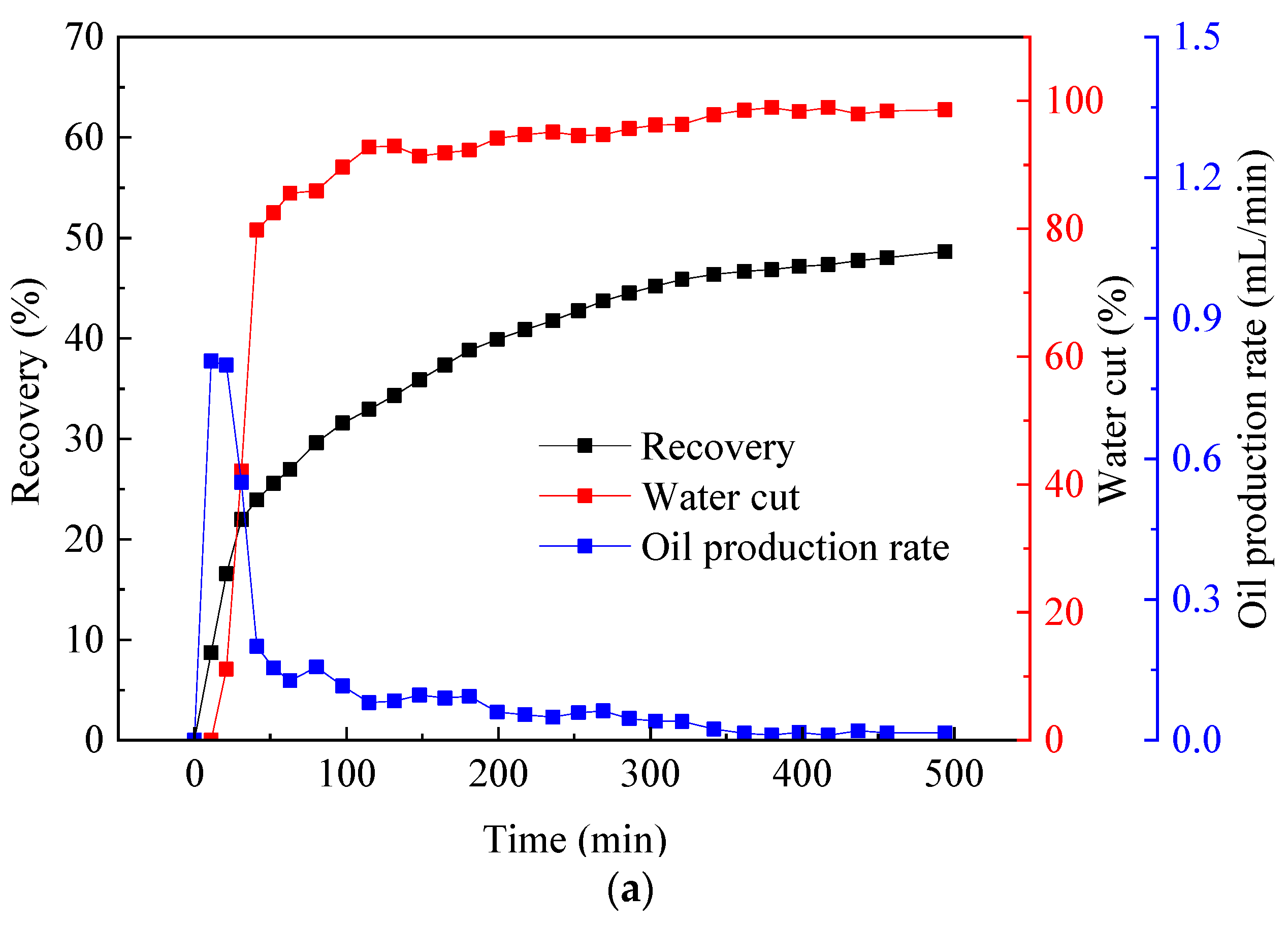
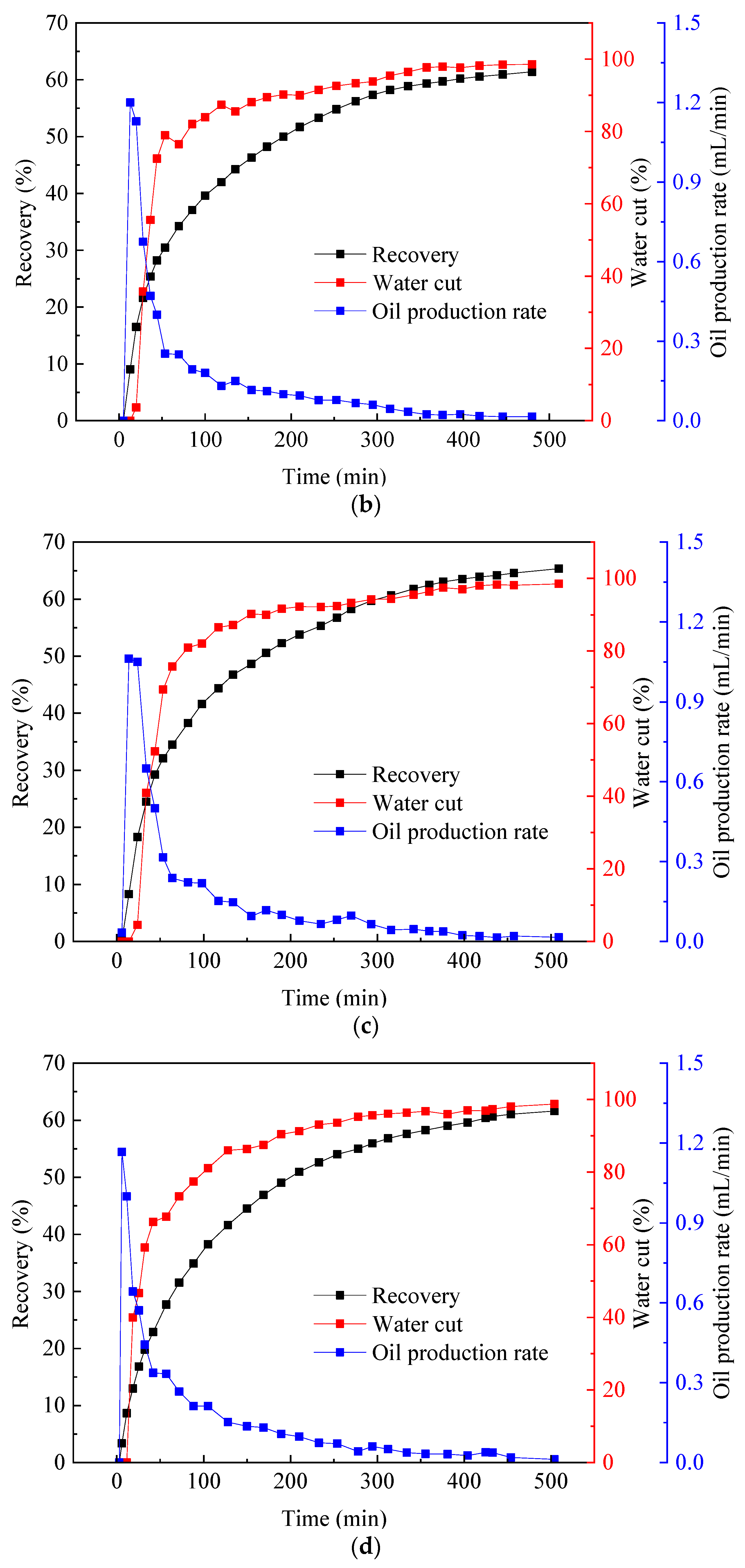
The liquid production characteristic curve included three parameters: recovery, water cut and oil production rate. For sandstone, the surface of the formation rock was mostly hydrophilic, and the seepage resistance of steam in the formation mainly came from the capillary force generated by the two-phase flow. In Figure 4, when the steam injection volume was approximately 0.3 PV, water started to appear at the outlet, and at this moment, the oil production rate reached a peak value of 0.81 mL/min. After that, due to the gradual formation of the dominant flow channel, the steam began to channel, and the water cut curve rose rapidly, corresponding to the rapid decrease in the oil production rate. During the subsequent displacement process, the flow of steam in the sandpack reached a steady state, the oil production rate fluctuated around the equilibrium value of 0.1 mL/min, and the recovery and water cut increased steadily as the remaining oil in the reservoir decreased. The ultimate recovery was near 48%, which was relatively low in terms of the thermal recovery of heavy oil.
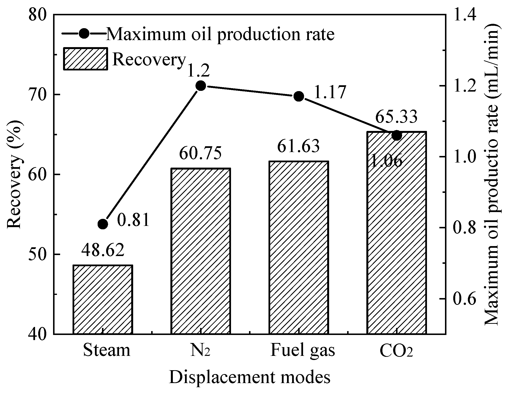
From Figure 4b–d, it could be found that after adding nonhydrocarbon gas, the variation law of oil displacement parameters was similar to that of pure steam flooding; that is, there were two stages: a high-producing period and a low-producing period. The high-producing period appeared in the early stage of displacement, and the oil production rate increased sharply at first and then decreased rapidly. The low-producing period appeared in the middle and late displacement stages, and the production rate decreased slowly and gradually stabilized. The maximum oil production rates of N2-assisted steam flooding, flue gas-assisted steam flooding, and CO2-assisted steam flooding were 1.2 mL/min, 1.17 mL/min (since the main component of flue gas was N2 and only a small amount of CO2 existed, the maximum oil production rate of flue gas-assisted steam flooding was very close to the former), and 1.06 mL/min, respectively, which were higher than that of pure steam flooding. In Figure 5, the steam mixed with the nonhydrocarbon gas flowed faster than pure steam in the formation, and the peak value was higher due to the lower seepage resistance of the gas, thereby improving the oil displacement efficiency.
Figure 5 shows that after adding nonhydrocarbon gas, the ultimate recovery was improved to different degrees. It is not difficult to understand that since the main composition of flue gas was also N2, the recovery of N2-assisted steam flooding was very close to that of flue gas-assisted steam flooding. Although the maximum oil production rate of CO2-assisted steam flooding was relatively lower, the high production period lasted for a longer time, so the final recovery degree was the highest.
3.2. Variation in the Pressure Difference during Displacement
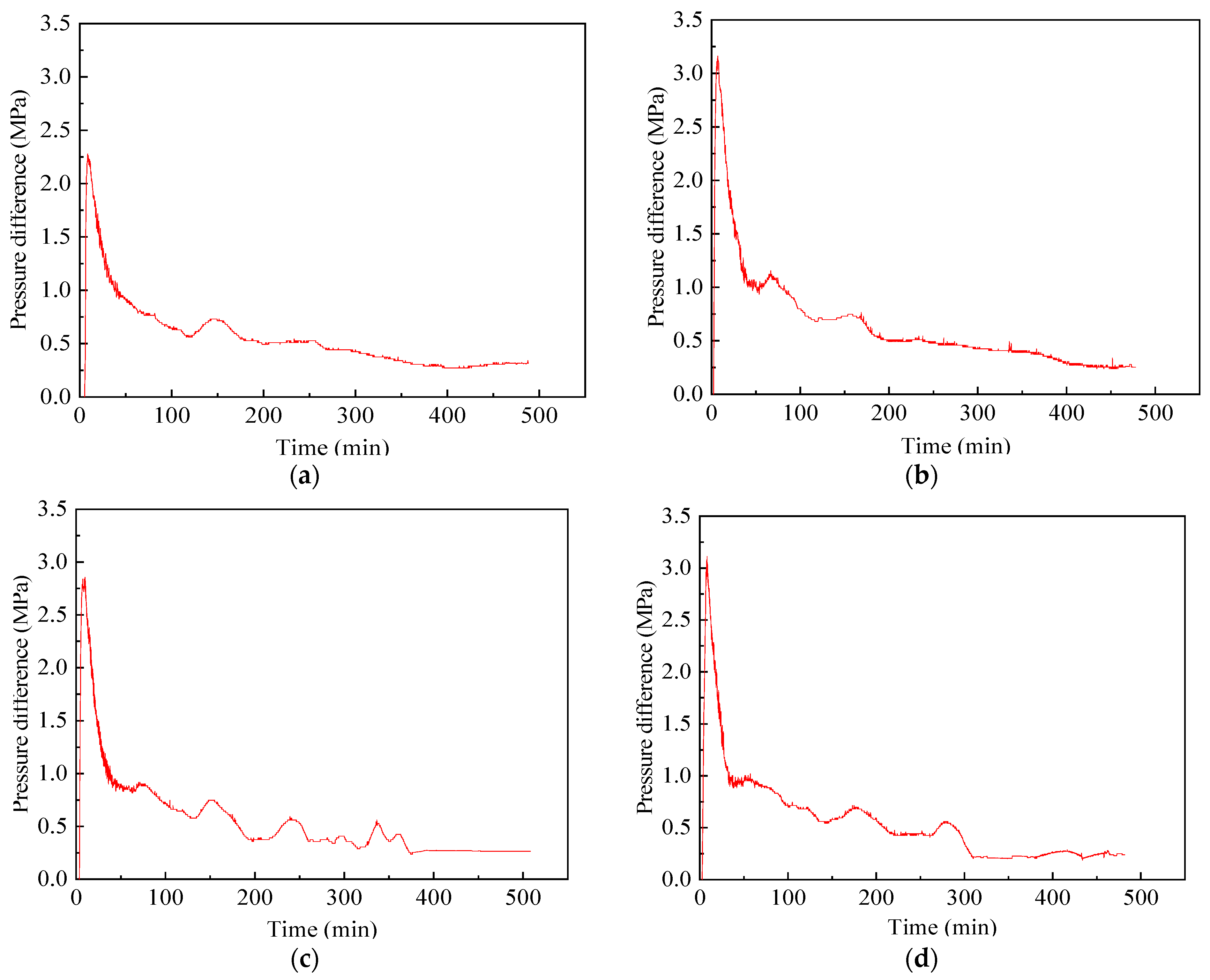
In Figure 6, the variation in the pressure difference of pure steam flooding and nonhydrocarbon gas-assisted steam flooding was similar, and the curve trends were basically the same. For a period of time when the steam was injected, the fluid flowed among the sand grains to open up the dominant channel for seepage. At this stage, no water was seen at the outlet, and the injection pressure increased rapidly, providing momentum for the flow of heavy oil. As the heavy oil along the dominant steam channel was continuously removed, high-permeability channels formed. After that, the flow resistance of steam/nonhydrocarbon gas dropped greatly, and a large amount of injected gas was channeled. Therefore, the displacement pressure suddenly dropped and finally remained stable with a small fluctuation. The heavy oil lying in the corners gradually expanded under the action of heat, occupying the large pores of fluid seepage, or the unstably filled sand particles formed displacement under the scouring of the steam/nonhydrocarbon gas, which slightly plugged the high-permeability channels. The pressure difference curves fluctuated in waves under this dynamic balance mechanism.
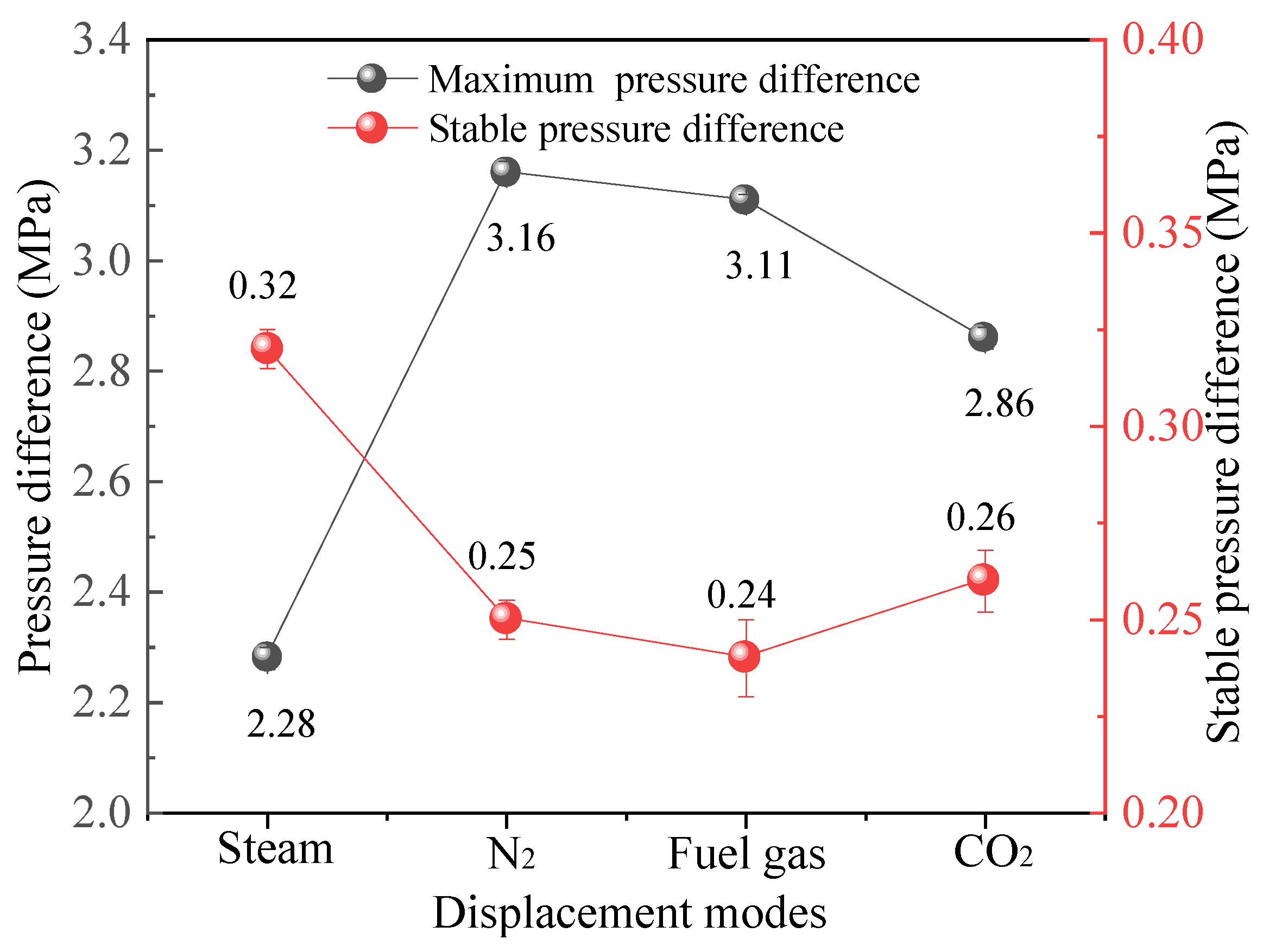
Further interpretation of the curves showed that the maximum displacement pressure difference of steam flooding was 2.28 MPa, and the maximum displacement pressure differences of N2-assisted steam flooding, flue gas-assisted steam flooding and CO2-assisted steam flooding were 3.16 MPa, 3.11 MPa and 2.86 MPa, respectively (Figure 7). After adding gas, the reasons why the maximum displacement pressure difference of each displacement mode was more than that of pure steam were as follows: First, in the high temperature and pressure conditions, the thermal motion of gas molecules was intensified, and the mixing degree of the two was higher. The dryness of the steam decreased, and the flow resistance of the mixed steam increased. Second, the non-condensate gas could form an insulating gas film on the surface of the rock particles, which prevented the direct contact between the steam and rock for heat exchange, and the viscosity of the heavy oil in the formation decreased slightly, resulting in a reduction in the flow capacity. In the later stage of displacement, due to the high gas mobility, the flow resistance of the mixed steam was reduced, so the stable pressure difference was lower than that of pure steam flooding. Compared with CO2, N2 was not easy to compress and had poor solubility in crude oil. Therefore, the maximum displacement pressure difference of N2-assisted steam flooding was significantly greater than that of the other two gases, which also showed that N2 possessed more ascendancies in supplementing the formation energy.
3.3. Variation in the Temperature Field
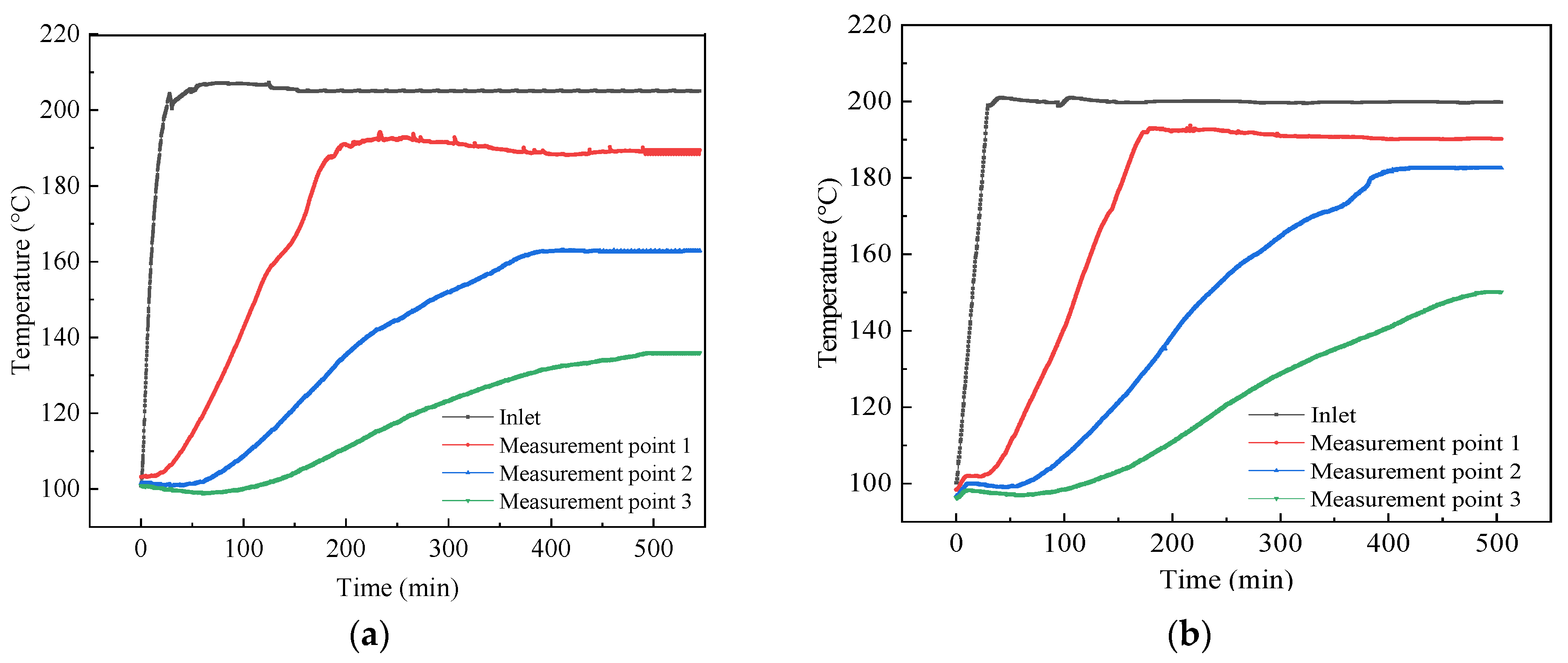
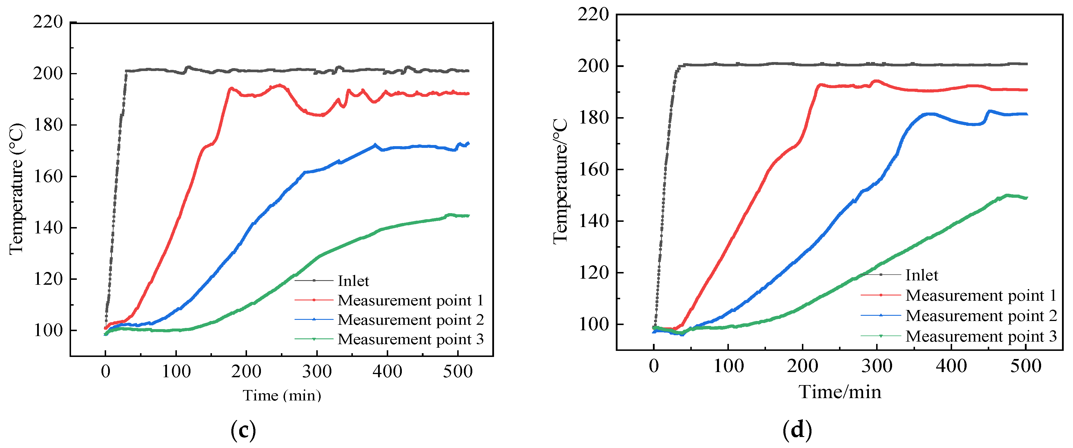
Figure 8 shows the temperature change process of the sandpack model under different displacement methods. The commonality was that as the steam front continued to advance into the deep reservoir, each temperature measurement point started to heat in sequence. The inlet first sensed the temperature change, and the curve increased nearly vertically and quickly reached a stable temperature. The temperature of the measurement points closer to the outlet end had a slower temperature rise, a longer heating time, and a lower stable temperature. It was determined that without changing the environmental conditions and injection parameters, the steam continuously exchanged heat with the formation rocks and fluids during the flow process, and with liquefaction and heat dissipation, its own temperature was lowered, inducing the heat it carried to be gradually reduced. Under the same displacement mode, the difference between the stable temperatures of adjacent temperature measurement points increased, indicating that the heat loss of the steam was severe along the way.
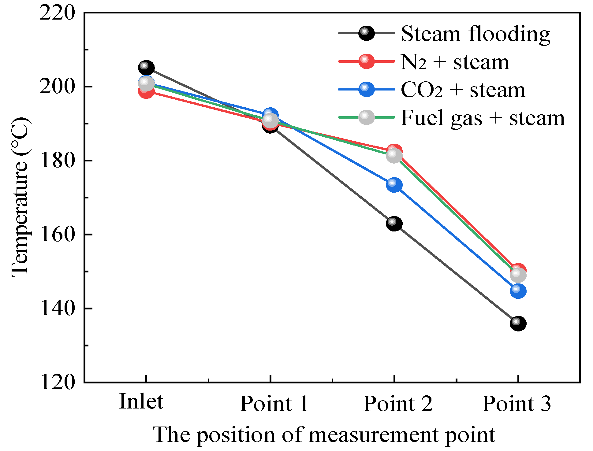
The stable temperature of each temperature measurement point under different displacement modes is shown in Figure 9 and Table 4. In pure steam flooding, the end temperature of the model was 135.9 °C, while it increased by 14.3 °C, 8.8 °C, and 13.1 °C in the steam flooding model assisted by N2, CO2, and flue gas, respectively. On the one hand, the addition of nonhydrocarbon gases improved the flow rate of the mixed thermal fluid. On the other hand, nonhydrocarbon gas would be enriched in the front edge of the flow, prompting heat exchange resistance between steam and rocks. Under the combined action of the two, the nonhydrocarbon gas spurred the steam to flow rapidly and reduced the heat loss in the low oil saturation region, thereby bringing more heat into the deep reservoir. The best effect of preventing the heat transfer mode was obtained with N2-assisted steam flooding, followed by flue gas, and CO2 was the worst because N2 was not easily compressed with a low thermal conductivity, and the energy-providing effect was outstanding, while CO2 had better dissolution and compressibility.
3.4. Distribution of the Remaining Oil
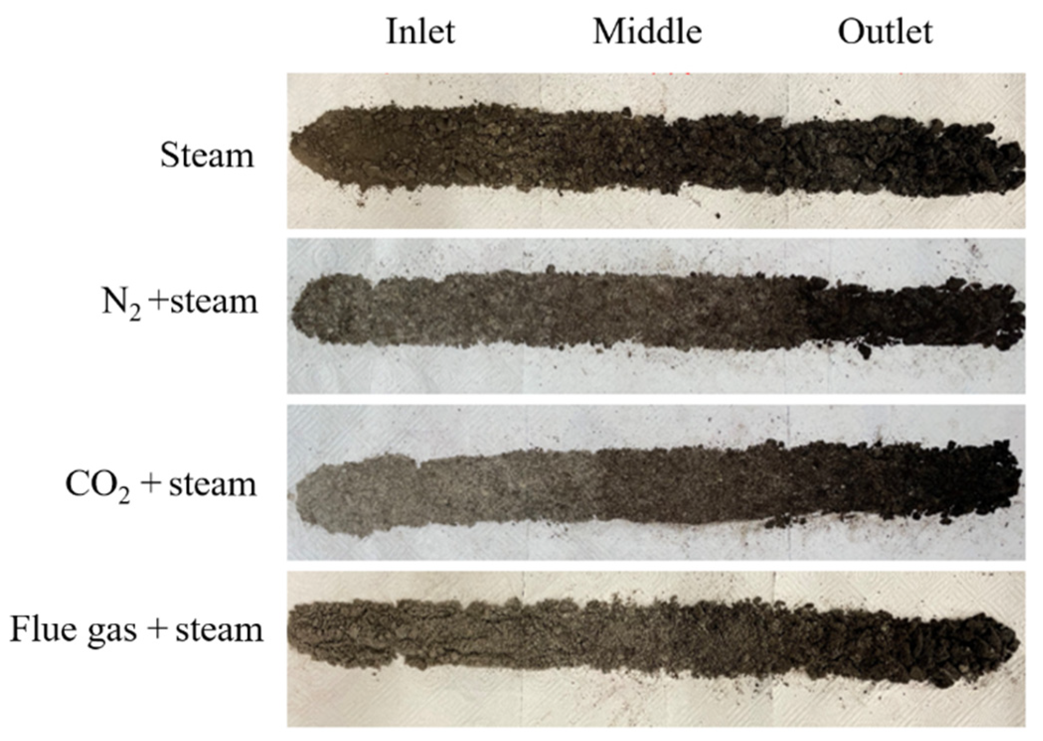
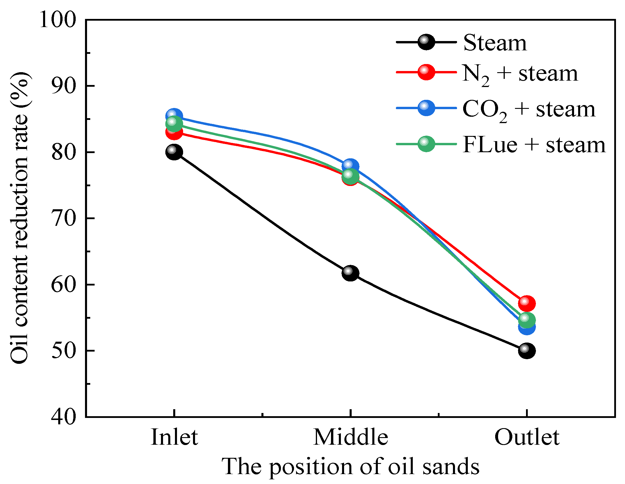
After flooding, samples were taken at different positions of the sandpack model to observe the distribution of the remaining oil, as shown in Figure 10. From the inlet to the outlet, the color of the oil sand became darker, and the oil content gradually increased. Due to the limited heat of the injected steam, the heavy oil near the inlet had the most obvious effect of heating up and reducing viscosity and had the highest recovery degree with an oil content of 5.15% (Table 5). Then, as the steam gradually liquefied and released heat, the heat brought to the rear of the reservoir dropped, and the oil content at the outlet was 12.88%. At the inlet and the middle position, the oil content of CO2-assisted steam flooding was lower than that of N2-assisted steam flooding, indicating that although CO2-assisted steam flooding was not as good as N2-assisted steam flooding in promoting the development of steam chambers, the oil recovery efficiency in the affected range was higher than that of N2-assisted steam flooding (Figure 11). Compared with steam flooding assisted by nonhydrocarbon gas, it was found that the color of the oil sand was obviously lighter, and the remaining oil content was reduced, indicating that the addition of nonhydrocarbon gas significantly improved the overall oil displacement efficiency. In the area affected by steam heat, the result of multiple mechanisms, such as temperature rise and viscosity reduction, thermal expansion, and CO2 extraction to light components, was that the oil recovery efficiency was greatly enhanced.
3.5. Analysis of the Reasons for the Effects Induced by Different Gases
From the above experimental results, some rules were determined. The mixing of the non-condensate gas with the steam increased the mobility of the displacement medium, thus prolonging the high production period and increasing the maximum oil recovery rate, because the gas was unable to liquefy into water when contacting cold objects, emitting much heat during the flow. The gas had a large molecular distance, and the viscous force between the molecules was mild, and the force generated by mutual shearing was significantly smaller than that of the liquid, so that it could quickly channel flow in the tiny pores, opening up the main path for the liquid flow and increasing the range of thermal spreading.
In terms of suppressing the heat transfer effect of condensation, the advantages of N2 were more obvious than those of CO2. After investigation, N2 had low thermal conductivity and low compressibility. Because of lower density and better mobility, the injected N2 could form a thermal isolation layer at the top of the reservoir. It not only inhibited steam override, but also prevented heat loss from the overlying rock, thus increasing thermal efficiency and sweep efficiency [24]. This was determined by the structure and physical properties of the gas molecules.
In terms of supplementing formation energy, compared with CO2, N2 was less compressible and insoluble in crude oil. Under the condition of the same injection amount, it could occupy a larger space, and better supplement formation energy, which provided higher displacement power and accelerated the advancement of thermal fluid to the deep formation, then expanding the swept range. This feature also positively affected the expansion of the heat spread.
In the aspect of enhancing oil recovery, CO2 could dissolve in crude oil under certain conditions and reduce its viscosity, which not only supplements crude oil energy, but also increases fluid pressure in porous media. At the same time, the two further formed a miscible phase, which greatly reduced the interfacial tension, thereby decreasing the seepage resistance. As a kind of common acid gas, CO2 also possessed a certain acid etching effect on rock particles that dissolved the cement between particles from the micro perspective, expanding the fluid flow space, and improving the flow capacity of the heavy oil originally located in the corner.
The research content of this paper was based only on the one-dimensional sandpack model of steam flooding. There are certain limitations in the testing and evaluation of oil production parameters, injection pressure and other indicators that affect the reservoir development effect, and the dynamic changes in the actual development process cannot be accurately predicted, but can provide a certain theoretical basis.
4. Conclusions
(1) Steam flooding assisted by three nonhydrocarbon gases, N2, CO2 and flue gas, could significantly improve the oil displacement efficiency, which was manifested as accelerated oil recovery and a prolonged high production period. Compared with that of pure steam flooding, the recovery factor was increased by 12.13%, 16.71% and 13.01%, respectively.
(2) The effect of enhancing the heat transfer of N2-assisted steam flooding was the best among the three nonhydrocarbon gases, and the CO2 effect was the worst. Compared with steam flooding, N2-, flue gas- and CO2-assisted steam flooding increased the temperature at the end of the sandpack by 14.3 °C, 13.1 °C and 8.8 °C, respectively. That is, N2 could bring more heat into the deep formation under the same conditions.
(3) N2 showed more evident assets in supplementing the formation energy. The maximum displacement pressure differences during steam flooding assisted by N2, CO2 and flue gas were 3.16 MPa, 2.86 MPa and 3.11 MPa, respectively.
(4) The oil content of the sands after undergoing CO2-assisted steam flooding was lower than that of N2-assisted steam flooding for the inlet and middle points of the sandpack, not the outlet, which indicated that CO2 had a more remarkable effect on oil displacement.
Author Contributions
Y.H. and W.X. mainly participated in the investigation of the research background and the integration of experimental data. S.C. and B.L. (Boliang Li) participated in the entire experimental process, including designing the experimental plan, recording the experimental detection data, etc. L.D. and B.L. (Binfei Li) mainly participated in the writing of the article. All authors have read and agreed to the published version of the manuscript.
Funding
The project was financially supported by National Natural Science Foundation of China (No. ZX20210203) and project: Research on the Mechanism and Parameter Optimization Design of Preliminary Non-hydrocarbon Gas Injection in Heavy Oil Old Areas.
Institutional Review Board Statement
Not applicable.
Informed Consent Statement
Not applicable.
Data Availability Statement
Not applicable.
Acknowledgments
We sincerely appreciate the researchers from the Shandong Engineering Research Center for Foam Application in Oil and Gas Field Development and Xinjiang Oilfield Engineering Technology Research Institute, Xinjiang Oilfield Heavy Oil Development Company for their assistance in this study. The valuable comments made by the anonymous reviewers are also sincerely appreciated. The authors would like to thank the reviewers for their helpful suggestions.
Conflicts of Interest
The authors declare that they have no known competing financial interests or personal relationships that could have appeared to influence the work reported in this paper.
References
- Pratama, R.A.; Babadagli, T. A review of the mechanics of heavy-oil recovery by steam injection with chemical additives. J. Pet. Sci. Eng. 2022, 208, 109717. [Google Scholar] [CrossRef]
- Dong, X.; Liu, H.; Chen, Z.; Wu, K.; Lu, N.; Zhang, Q. Enhanced oil recovery techniques for heavy oil and oilsands reservoirs after steam injection. Appl. Energy 2019, 239, 1190–1211. [Google Scholar] [CrossRef]
- Taylor, S.E. Interfacial chemistry in steam-based thermal recovery of oil sands bitumen with emphasis on steam-assisted gravity drainage and the role of chemical additives. Colloids Interfaces 2018, 2, 16. [Google Scholar] [CrossRef] [Green Version]
- Xu, X.; He, Y. Blockchain application in modern logistics information sharing: A review and case study analysis. Prod. Plan. Control 2022, 1–15. [Google Scholar] [CrossRef]
- Cokar, M.; Kallos, M.S.; Gates, I.D. Reservoir simulation of steam fracturing in early-cycle cyclic steam stimulation. SPE Reserv. Eval. Eng. 2012, 15, 676–687. [Google Scholar] [CrossRef]
- Butler, R.; Yee, C. Progress in the in situ recovery of heavy oils and bitumen. J. Can. Pet. Technol. 2002, 41, 31–40. [Google Scholar] [CrossRef]
- Xu, X.; Wang, C.; Zhou, P. GVRP considered oil-gas recovery in refined oil distribution: From an environmental perspective. Int. J. Prod. Econ. 2021, 235, 108078. [Google Scholar] [CrossRef]
- Feng, G.; Li, Y.; Yang, Z. Performance evaluation of nitrogen-assisted steam flooding process in heavy oil reservoir via numerical simulation. J. Pet. Sci. Eng. 2020, 189, 106954. [Google Scholar] [CrossRef]
- Pang, Z.; Wang, L.; Yin, F.; Lyu, X. Steam chamber expanding processes and bottom water invading characteristics during steam flooding in heavy oil reservoirs. Energy 2021, 234, 121214. [Google Scholar] [CrossRef]
- Irani, M.; Gates, I. Understanding the Convection Heat-Transfer Mechanism in the Steam-Assisted-Gravity-Drainage Process. SPE J. 2013, 18, 1202–1216. [Google Scholar] [CrossRef]
- Sivakumar, P.; Krishna, S.; Hari, S.; Vij, R.K. Electromagnetic heating, an eco-friendly method to enhance heavy oil production: A review of recent advancements. Environ. Technol. Innov. 2020, 20, 101100. [Google Scholar] [CrossRef]
- Hu, L.; Andy Li, H.; Babadagli, T.; Ahmadloo, M. A semianalytical model for simulating combined electromagnetic heating and solvent-assisted gravity drainage. SPE J. 2018, 23, 1248–1270. [Google Scholar] [CrossRef]
- Hu, L.; Li, H.A.; Babadagli, T.; Ahmadloo, M. Experimental investigation of combined electromagnetic heating and solvent-assisted gravity drainage for heavy oil recovery. J. Pet. Sci. Eng. 2017, 154, 589–601. [Google Scholar] [CrossRef]
- Paz, P.Z.; Hollmann, T.H.; Kermen, E.; Chapiro, G.; Slob, E.; Zitha, P.L. EM Heating-Stimulated Water Flooding for Medium–Heavy Oil Recovery. Transp. Porous Media 2017, 119, 57–75. [Google Scholar] [CrossRef] [Green Version]
- Wang, X.; Li, X.; Liu, S.; Zhou, H.; Li, Q.; Yang, J. Cis-9-Octadecenylamine modified ferric oxide and ferric hydroxide for catalytic viscosity reduction of heavy crude oil. Fuel 2022, 322, 124159. [Google Scholar] [CrossRef]
- Zhao, Y. Laboratory experiment and field application of high pressure and high quality steam flooding. J. Pet. Sci. Eng. 2020, 189, 107016. [Google Scholar] [CrossRef]
- Pratama, R.A.; Babadagli, T. Reconsideration of Steam Additives to Improve Heavy-Oil Recovery Efficiency: Can New Generation Chemicals Be a Solution for Steam-Induced Unfavorable Wettability Alteration? Energy Fuels 2020, 34, 8283–8300. [Google Scholar] [CrossRef]
- Pratama, R.A.; Babadagli, T. Wettability state and phase distributions during steam injection with and without chemical additives: An experimental analysis using visual micromodels. SPE Reserv. Eval. Eng. 2020, 23, 1133–1149. [Google Scholar] [CrossRef]
- Wang, Z.; Li, S.; Li, Z. A novel strategy to reduce carbon emissions of heavy oil thermal recovery: Condensation heat transfer performance of flue gas-assisted steam flooding. Appl. Therm. Eng. 2022, 205, 118076. [Google Scholar] [CrossRef]
- Alomair, O.A.; Alajmi, A.F. A novel experimental nanofluid-assisted steam flooding (NASF) approach for enhanced heavy oil recovery. Fuel 2022, 313, 122691. [Google Scholar] [CrossRef]
- Bai, Y.; Lian, Y.; Zhao, J.; Cao, Z.; Sun, J.; Zhang, H. Thermal-insulation and temperature-resistant foamed gel for thermal management of heavy oil steam flooding. J. Mol. Liq. 2022, 359, 119304. [Google Scholar] [CrossRef]
- Pang, Z.; Liu, H.; Zhu, L. A laboratory study of enhancing heavy oil recovery with steam flooding by adding nitrogen foams. J. Pet. Sci. Eng. 2015, 128, 184–193. [Google Scholar] [CrossRef]
- Xi, C.; Qi, C.; Zhang, Y.; Liu, T.; Shen, D.; Mu, H.; Dong, H.; Li, X.; Jiang, Y.; Wang, H. CO2 assisted steam flooding in late steam flooding in heavy oil reservoirs. Pet. Explor. Dev. 2019, 46, 1242–1250. [Google Scholar] [CrossRef]
- Wu, Z.; Wang, L.; Xie, C.; Yang, W. Experimental investigation on improved heavy oil recovery by air assisted steam injection with 2D visualized models. Fuel 2019, 252, 109–115. [Google Scholar] [CrossRef]
Figure 1.
The relationship between the viscosity and temperature of the heavy oil used in the experiment.
Figure 1.
The relationship between the viscosity and temperature of the heavy oil used in the experiment.

Figure 2.
Schematic diagram of the experimental setup in the laboratory.

Figure 3.
The sandpack with three temperature probes: (a) is a schematic diagram and (b) is a real picture.
Figure 3.
The sandpack with three temperature probes: (a) is a schematic diagram and (b) is a real picture.

Figure 4.
The liquid production characteristic curves under different flooding methods: (a) pure steam flooding, (b) N2 + steam flooding, (c) CO2 + steam flooding, and (d) flue gas + steam flooding.
Figure 4.
The liquid production characteristic curves under different flooding methods: (a) pure steam flooding, (b) N2 + steam flooding, (c) CO2 + steam flooding, and (d) flue gas + steam flooding.


Figure 5.
Maximum oil production rate and recovery under different displacement methods.

Figure 6.
Variation in the displacement pressure difference under different displacement modes: (a) pure steam flooding, (b) N2 + steam flooding, (c) CO2 + steam flooding, and (d) flue gas + steam flooding.
Figure 6.
Variation in the displacement pressure difference under different displacement modes: (a) pure steam flooding, (b) N2 + steam flooding, (c) CO2 + steam flooding, and (d) flue gas + steam flooding.

Figure 7.
Maximum pressure difference and stable pressure difference under different displacement methods.
Figure 7.
Maximum pressure difference and stable pressure difference under different displacement methods.

Figure 8.
Temperature variation at temperature measurement points under different flooding modes: (a) pure steam flooding, (b) N2 + steam flooding, (c) CO2 + steam flooding, and (d) flue gas + steam flooding.
Figure 8.
Temperature variation at temperature measurement points under different flooding modes: (a) pure steam flooding, (b) N2 + steam flooding, (c) CO2 + steam flooding, and (d) flue gas + steam flooding.


Figure 9.
The comparative curves of the stable temperature of the measurement points under different displacement modes.
Figure 9.
The comparative curves of the stable temperature of the measurement points under different displacement modes.

Figure 10.
The distribution of the remaining oil under different displacement methods.

Figure 11.
Comparison of oil content reduction rate of oil sands after displacement.


Table 1.
Parameters of the sandpack used in the flooding experiment.
| Displacement | Length/cm | Diameter/cm | Porosity/% | Permeability/mD | Back Pressure/MPa |
|---|---|---|---|---|---|
| Steam flooding | 60 | 2.54 | 33.1 | 1184 | 1 |
| N2-assisted steam flooding | 60 | 2.54 | 34.17 | 1230 | 1 |
| CO2-assisted steam flooding | 60 | 2.54 | 33.18 | 1152 | 1 |
| Flue gas-assisted steam flooding | 60 | 2.54 | 33.84 | 1203 | 1 |
Table 2.
Relevant parameters of experimental equipment.
| Device | Type |
|---|---|
| Gas flow controller | Model Sla58550, Brooks, United States, flow rate range of 0–30 mL/min under standard conditions |
| High-precision syringe pump | Model 100DX, Teledyne ISCO Company, Teledyne Co., Ltd., USA, flow accuracy of ± 0.25 μL/min and pressure accuracy of ± 0.5% |
| Steam generator | Model GL-1, Haian Petroleum Equipment Company, temperature range of 100–350 °C and pressure range of 0.1–25 MPa |
| Thermocouples | Model K, Haian Petroleum Equipment Company, temperature accuracy of ± 0.1 °C |
Table 3.
Injection parameters of various displacement experiments.
| Steam Flow Rate/(mL·min−1) | Steam Dryness | Gas Flow Rate/(mL·min−1) | Back Pressure/MPa |
|---|---|---|---|
| 1 | 0.7 | 1 | 1 |
Table 4.
The stable temperature of the measurement points under different displacement modes.
| Displacement Mode | Inlet/°C | Measurement Point 1/°C | Measurement Point 2/°C | Measurement Point 3/°C |
|---|---|---|---|---|
| Steam | 205.1 | 189.4 | 162.9 | 135.9 |
| N2 + steam | 198.8 | 190.2 | 182.5 | 150.2 |
| CO2 + steam | 201 | 192.3 | 173.4 | 144.7 |
| Flue gas + steam | 200.8 | 190.8 | 181.3 | 149 |
Table 5.
The oil content of oil sands at different positions after displacement.
| Oil Content/%. | Position | ||
|---|---|---|---|
| Displacement Modes | Inlet | Middle | Outlet |
| Initial oil sands | 25.77 | 25.77 | 25.77 |
| Steam | 5.15 | 9.86 | 12.88 |
| N2 + steam | 4.37 | 6.15 | 11.05 |
| CO2 + steam | 3.76 | 5.72 | 11.95 |
| Flue gas + steam | 4.05 | 6.1 | 11.69 |
Publisher’s Note: MDPI stays neutral with regard to jurisdictional claims in published maps and institutional affiliations. |
© 2022 by the authors. Licensee MDPI, Basel, Switzerland. This article is an open access article distributed under the terms and conditions of the Creative Commons Attribution (CC BY) license (https://creativecommons.org/licenses/by/4.0/).
Share and Cite
MDPI and ACS Style
Huang, Y.; Xiao, W.; Chen, S.; Li, B.; Du, L.; Li, B. A Study on the Adaptability of Nonhydrocarbon Gas-Assisted Steam Flooding to the Development of Heavy Oil Reservoirs. Energies 2022, 15, 4805. https://doi.org/10.3390/en15134805
AMA Style
Huang Y, Xiao W, Chen S, Li B, Du L, Li B. A Study on the Adaptability of Nonhydrocarbon Gas-Assisted Steam Flooding to the Development of Heavy Oil Reservoirs. Energies. 2022; 15(13):4805. https://doi.org/10.3390/en15134805
Chicago/Turabian StyleHuang, Yong, Wulin Xiao, Sen Chen, Boliang Li, Liping Du, and Binfei Li. 2022. "A Study on the Adaptability of Nonhydrocarbon Gas-Assisted Steam Flooding to the Development of Heavy Oil Reservoirs" Energies 15, no. 13: 4805. https://doi.org/10.3390/en15134805
Note that from the first issue of 2016, this journal uses article numbers instead of page numbers. See further details here.