
Symmetry Detection and Topological Synthesis of Mechanisms of Powertrains


School of Mechanical Engineering and Electronic Information, China University of Geosciences, Wuhan 430074, China
*
Author to whom correspondence should be addressed.
Energies 2022, 15(13), 4755; https://doi.org/10.3390/en15134755
Submission received: 15 May 2022
/
Revised: 15 June 2022
/
Accepted: 16 June 2022
/
Published: 28 June 2022
(This article belongs to the Special Issue New Trends of Power Electronics Technology and Application in Energy Field)
Abstract
:The function of vehicle powertrains (including hybrid powertrains) is to transmit power from the power source (engine or electric machine) to driving wheels. The planetary gear train (PGT) is a core structure of mechanisms of powertrains. The detection of topological symmetry is helpful for improving the efficiency of mechanism design. In this paper, we present a fully automatic and reliable method for detecting symmetry of plane kinematic chains and extend this method to symmetry detection and the topological design of mechanisms of powertrains. First, the topological model and adjacency matrix are introduced to represent various kinds of plane kinematic chains. Then, the moment matrix of the kinematic chain is established to obtain link groups, based on which we propose an algorithm to generate the unique numerical code of each link and precisely detect the symmetry. Our method is applied to synthesize different kinds of plane kinematic chains and mechanisms, which can improve the design efficiency of mechanisms of powertrains and other mechanical devices.
1. Introduction
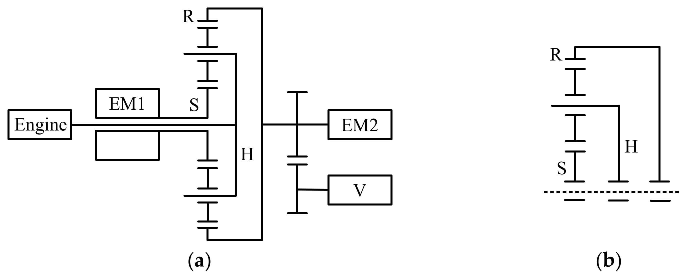
The function of vehicle powertrains is to transmit power from the power source to the driving wheels, and planetary gear trains (PGTs) are widely used as the core structure of the mechanisms of powertrains [1,2,3]. For example, Figure 1a is the architecture of the Toyota Prius 2004 hybrid powertrain, and the core structure of Figure 1a is shown in Figure 1b, which is a four-link one-degree-of-freedom (DOF) PGT. A PGT is a special kind of kinematic chain containing both revolute and geared pairs. Figure 2a shows a linkage kinematic chain which only contains revolute pairs. This kind of kinematic chain is also widely used in the mechanisms of various mechanical devices.
The creation of novel mechanisms is the key to develop mechanical devices and systems. One of the effective mechanism design methods is based on the structural synthesis of kinematic chains [4,5]. In the conceptual design of mechanisms, the avoidance of isomorphic (topologically identical) mechanisms is an essential and troublesome problem. The symmetry information of kinematic chains can be used to resolve this issue and enhance the efficiency of mechanism design [6,7].
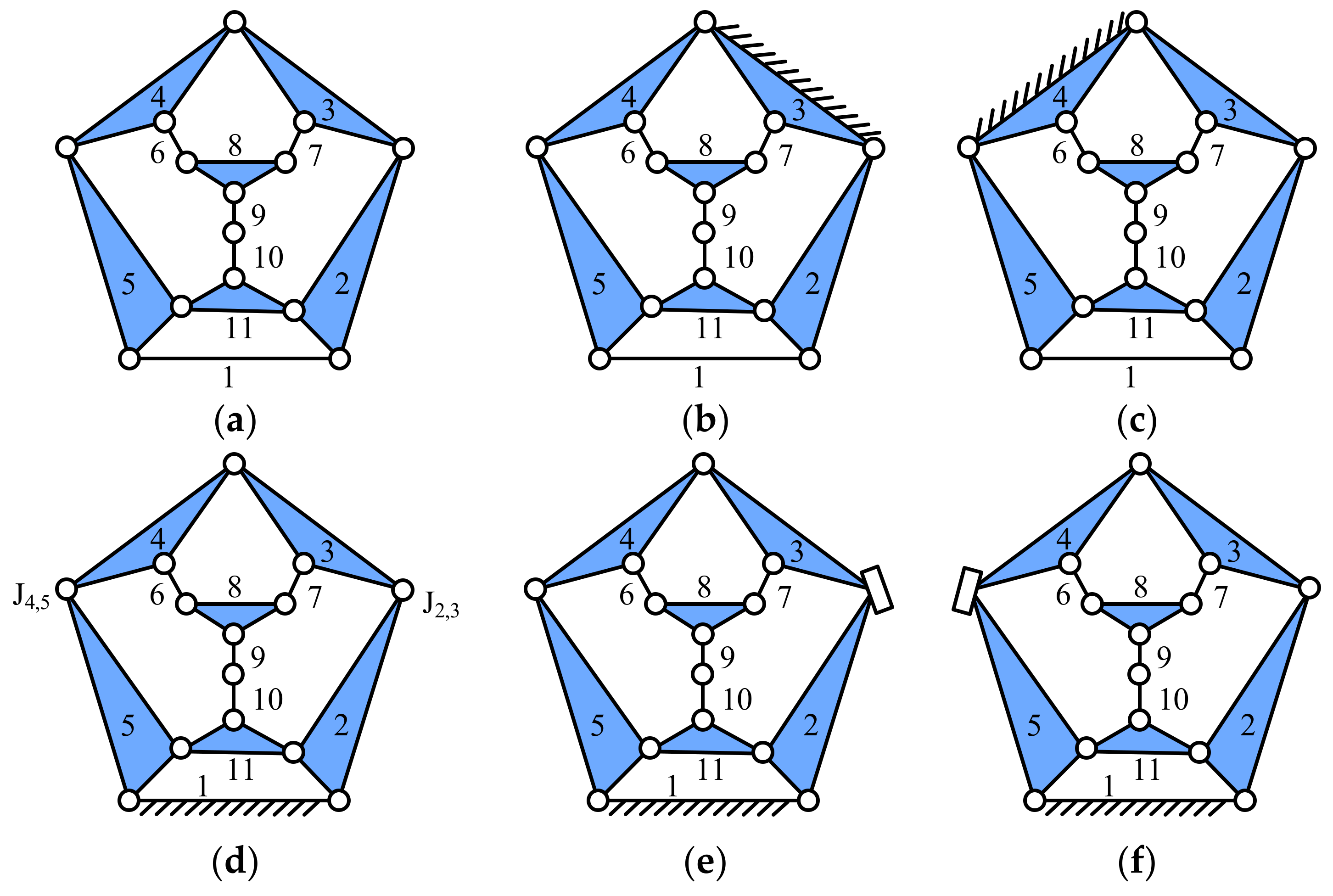
Two links/joints are said to be symmetric (or similar) if they have the same topological characteristics. For a given kinematic chain, if two symmetric links are assigned as functional links, such as ground links, input links, and output links, the generated mechanisms are isomorphic; similarly, if two symmetric revolute pairs are transformed into other types of kinematic pairs, such as prismatic pairs, geared pairs, and cam pairs, the generated mechanisms are also isomorphic. For example, Figure 2a is an 11-link two-DOF simple joint kinematic chain, where links 2 and 5, links 3 and 4, and links 6 and 7 are symmetric, respectively. By assigning links 3 and 4 as ground links, the derived kinematic chain inversions, shown in Figure 2b,c, are isomorphic. Similarly, the revolute joints J2,3 and J4,5 in Figure 2d are symmetric. By transforming these two joints as prismatic pairs, the derived mechanisms shown in Figure 2e,f are isomorphic. Obviously, the research on the symmetry of kinematic chains is of great significance because it can be used to avoid the generation of isomorphic mechanisms.
Mruthyunjaya and Balasubramanian [8,9,10] applied the characteristic polynomial to obtain nonsymmetric ground links and synthesize 8, 9 and 10-link kinematic chain inversions. Rao and Varada Raju [11,12] introduced the concept of Hamming matrix of the kinematic chain and studied the detection of symmetric links by comparing their Hamming strings. Yan and his coworkers [6,13,14] developed an algorithm to detect symmetric links and joints based on the concept of the permutation group. The symmetry information was used to enumerate nonisomorphic specialized mechanisms. Kim and Kwak [15] developed a method to generate the edge list of graphs based on the level structure of kinematic chains, and the edge list was used to detect the symmetric links of kinematic chains. Chu and Cao [16] proposed the link’s adjacent-chain table as an invariant to study the symmetry of kinematic chains. Nonsymmetric links were selected as the ground links of the kinematic chain inversions. Yadav et al. [17,18] developed algorithms based on link-path codes to distinguish the nonsymmetric links of the kinematic chains. Wang and Yan [7] presented a method to detect the link symmetry based on the weights of links. This method was applied to avoid isomorphic configuration schemes and enhance the efficiency in the conceptual design of the plane mechanisms. Tuttle and his coworkers [19,20] presented a famous technique to detect the symmetric links of kinematic chains based on symmetry groups. This technique played an important role in their structural synthesis of kinematic chains and kinematic chain inversions.
Rao and Prasad Raju Pathapati [21] developed a loop-based invariant, called the link adjacency string, to identify nonsymmetric links of kinematic chains with up to 10 links. Kuo and Shih [22] applied the concept of pseudogenetic computation to generate vertex family strings, which were used to identify symmetric links and joints of plane kinematic chains and mechanisms. Simoni et al. [23] studied the symmetry of kinematic chains based on the group of automorphisms and enumerated kinematic chain inversions with up to four independent loops. Dargar et al. [24] acquired a kind of structural invariant to synthesize kinematic chain inversions whose ground links are nonsymmetric. Nie et al. [25,26] developed a kind of weight code and similarity code for the detection of symmetric links, and the configuration analysis and synthesis of kinematic chains. Yang et al. [27] developed a perimeter loop-based method to determine nonsymmetric links and synthesize nonisomorphic kinematic chain inversions with complex topology. Based on the link adjacency relationship, Deng et al. [28] developed the extended adjacency identification index to recognize symmetric links and joints of various kinds of kinematic chains. Sun and his coworkers [29,30,31] presented a method based on the power of adjacency matrix to detect symmetric links and joints. This method was applied to eliminate isomorphism in the synthesis of kinematic chains.
The symmetry detection method is desired to be reliable. Only in this way can isomorphism be precisely eliminated when synthesizing and designing mechanisms. However, many existing methods cannot guarantee reliability because they fail in some cases, as discussed in Refs. [27,28]. On the other hand, most studies only focused on the kinematic chains with simple joints, whereas other types of kinematic chains, such as those chains containing multiple joints, prismatic pairs, and geared pairs, were rarely discussed.
In this paper, we present a fully automatic and reliable method for detecting symmetry of various kinds of kinematic chains and extend this method to the symmetry detection and the topological design of mechanisms of powertrains. First, the topological model and adjacency matrix are introduced to represent kinematic chains. Then, the moment matrix of the kinematic chain is established to obtain link groups, based on which we propose an algorithm to generate the unique numerical code of each link and precisely detect the symmetry. The detection procedure is fully automatic, and our method is applied to synthesize different kinds of plane kinematic chains and mechanisms, which can improve the design efficiency of mechanisms of powertrains and other mechanical devices.
2. Topological Model and Adjacency Matrix of Kinematic Chains
For the convenience of establishing a mathematical model and computer processing, topological models and adjacency matrices are introduced to represent kinematic chains.
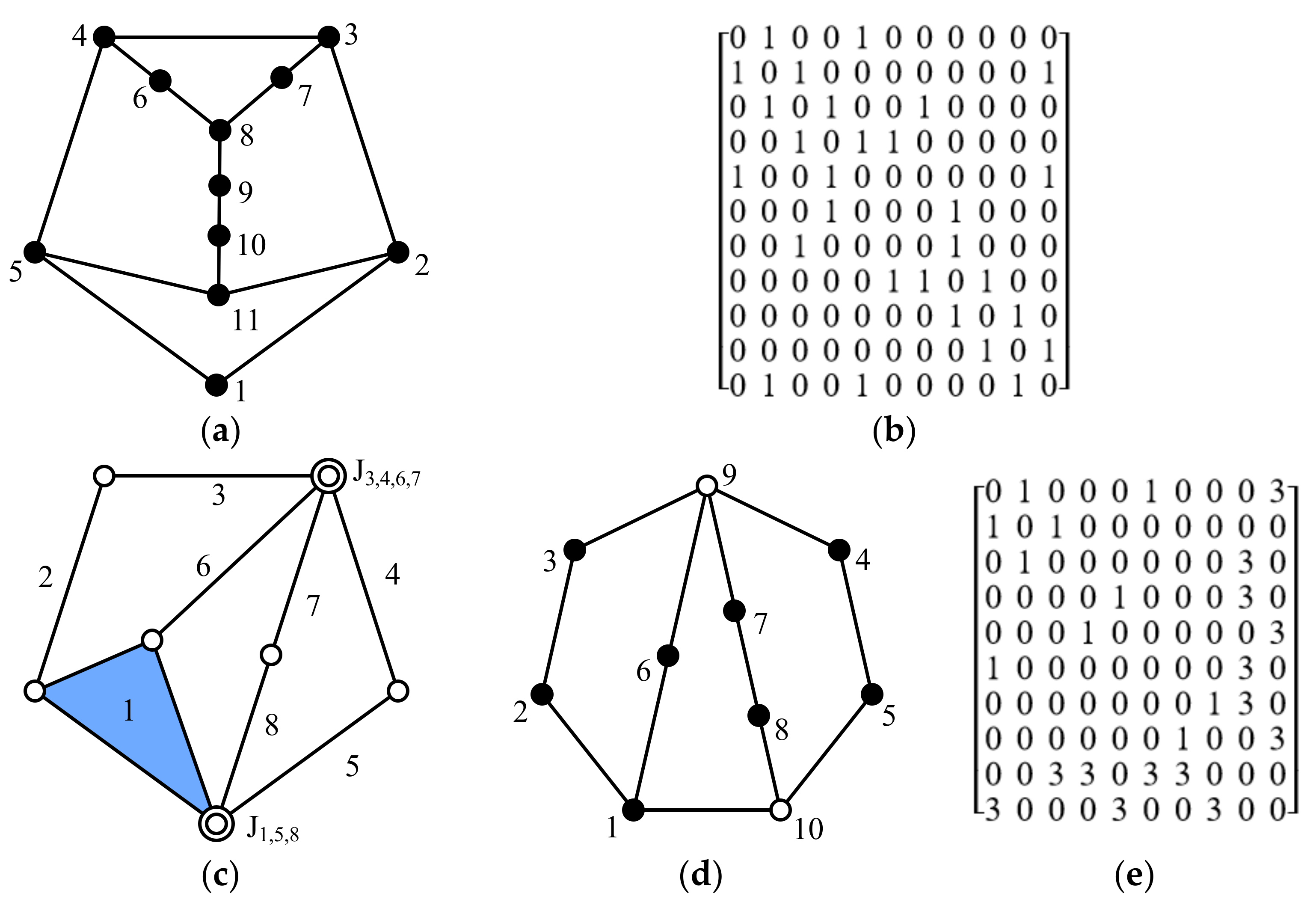
In the topological model of the simple joint kinematic chain, a vertex denotes a link, and an edge denotes a revolute pair. For example, the topological model of Figure 2a is shown in Figure 3a. Its corresponding vertex–vertex adjacency matrix is defined by Equation (1), where n is the number of vertices, and the revolute edge is given the weight of 1. By definition, the adjacency matrix of Figure 3a is shown in Figure 3b.
If more than two links are connected by a shared revolute pair, this pair is called a multiple joint. In the topological model of the multiple joint kinematic chain, a hollow vertex denotes a multiple joint and a solid vertex denotes a link. For example, Figure 3c shows an 8-link 1-DOF multiple joint kinematic chain whose joints J1,5,8 and J3,4,6,7 are multiple joints, and its topological model is shown in Figure 3d. The corresponding vertex–vertex adjacency matrix is defined by Equation (2), where the edge incident with a hollow vertex is given the weight of 3. For example, the adjacency matrix of Figure 3d is shown in Figure 3e.
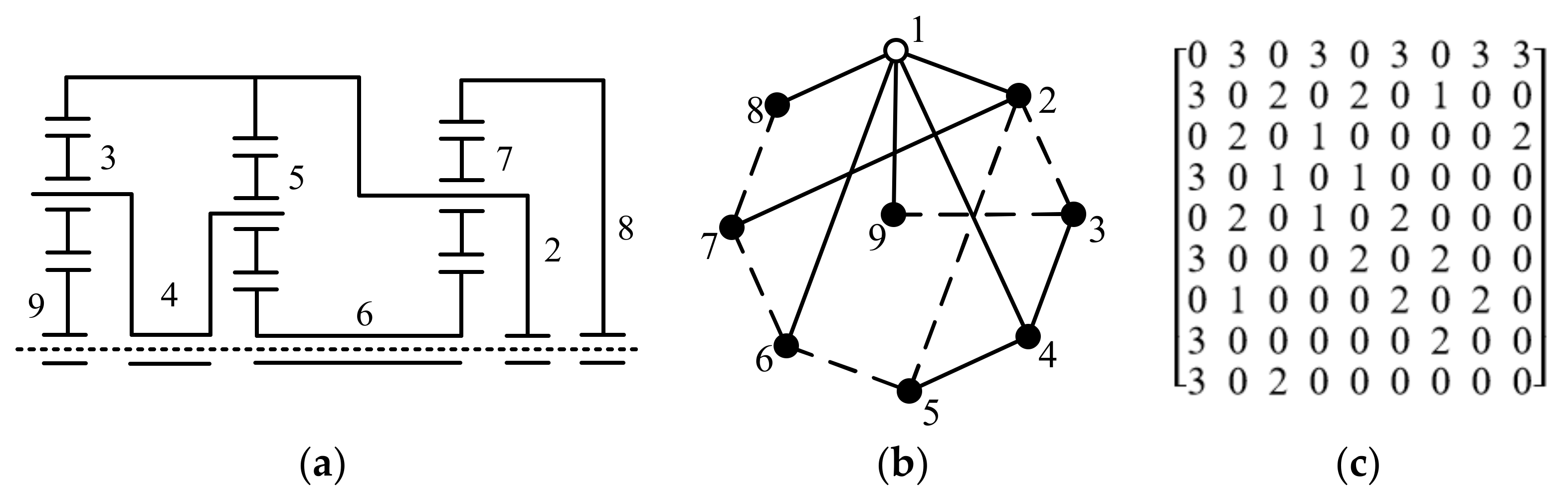
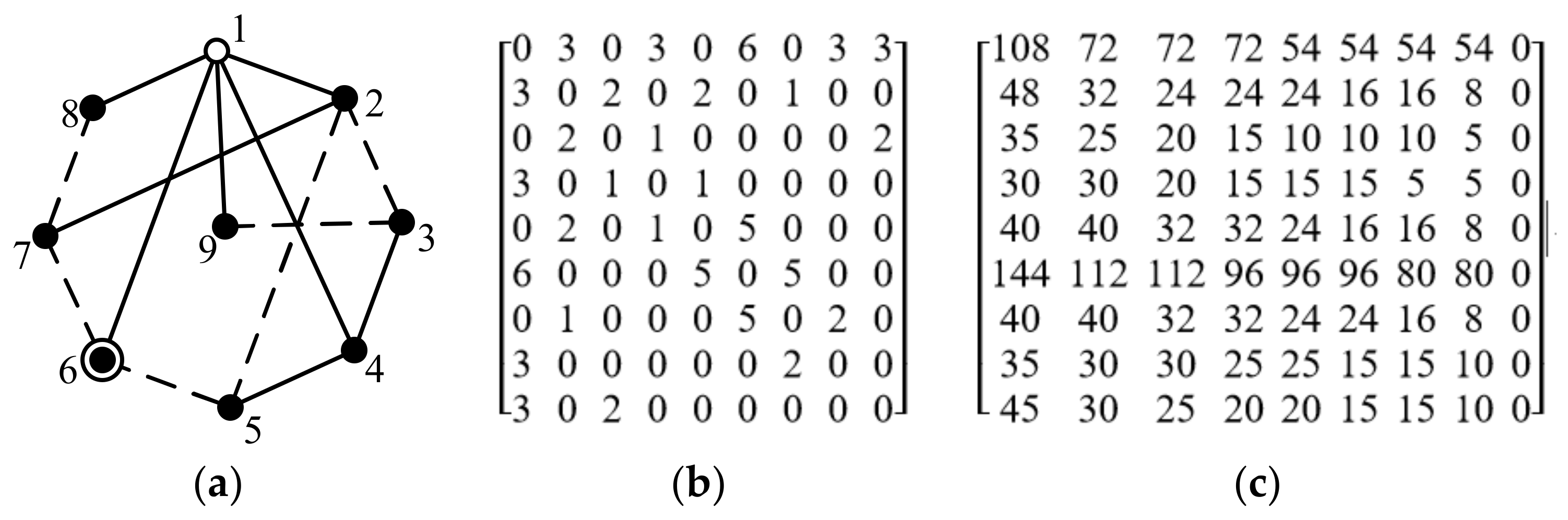
In the topological model of planetary gear train, a dashed edge denotes a geared pair, and a solid edge denotes a revolute pair. For example, Figure 4a shows an 8-link 1-DOF planetary gear train, and Figure 4b is its topological model. The corresponding vertex–vertex adjacency matrix is defined by Equation (3). In order to distinguish revolute and geared pairs, a dashed edge is given the weight of 2. For example, the adjacency matrix of Figure 4b is shown in Figure 4c.
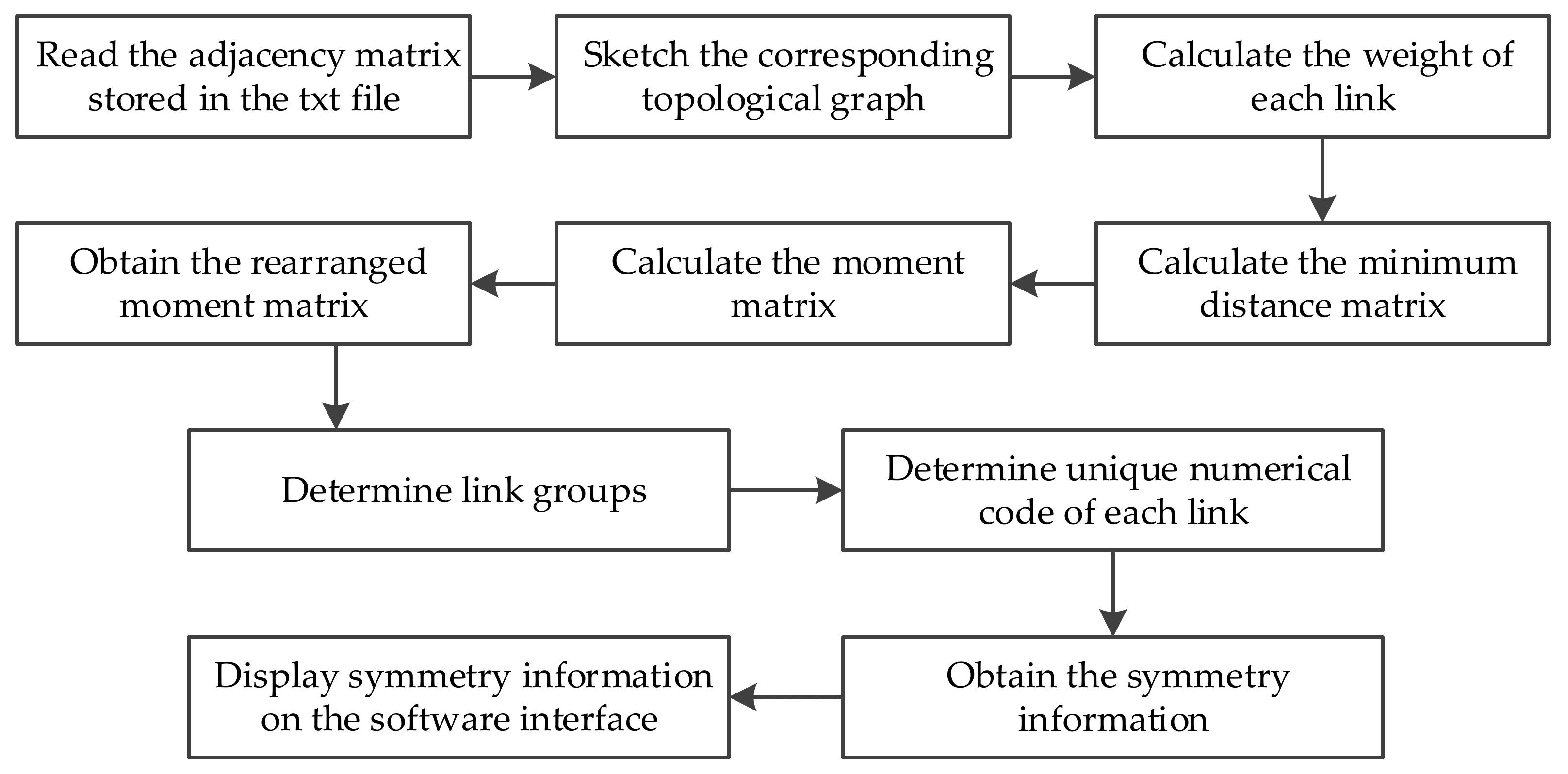
In the definition of the adjacency matrix, edge weights of 1, 2, and 3 are used to distinguish different types of edges. In fact, the values of the edge weights can be any different numbers, and their values do not affect the symmetry detection result. Our present symmetry detection method is fully automatic, and the adjacency matrix is the only input data needed to develop the computer software. Upper triangular elements of the adjacency matrix are stored in a txt file, and the computer software performs the symmetry detection work by reading and processing the data of adjacency matrix. The flow chart of our automatic symmetry detection method is illustrated in Figure 5.
3. Moment Matrix of Kinematic Chain
Symmetric links have the same topological characteristics and attributes. The symmetry detection aims to develop a structural invariant or index to distinguish symmetric and nonsymmetric links. In this section, we propose the concept of moment matrix for the symmetry detection task. The advantageous features are that the moment matrix can be directly derived from the adjacency matrix, and it can distinguish symmetric and nonsymmetric links efficiently.
3.1. Weight of a Link
The weight of a link is defined as the sum of weights of edges incident with this link. This parameter can be easily obtained from the adjacency matrix of kinematic chain. That is, the weight of link i is the sum of elements in row i. For example, Figure 6a shows a 10-link 1-DOF simple joint kinematic chain, and Figure 6b is its adjacency matrix. The weight of link 1 is the sum of elements in row 1, i.e., 0 + 1 + 0 + 0 + 1 + 0 + 1 + 1 + 0 + 1 = 5. Similarly, the weights of links 2–10 are equal to 2, 2, 4, 3, 2, 2, 2, 2, 2, respectively.
3.2. Minimum Distance Matrix
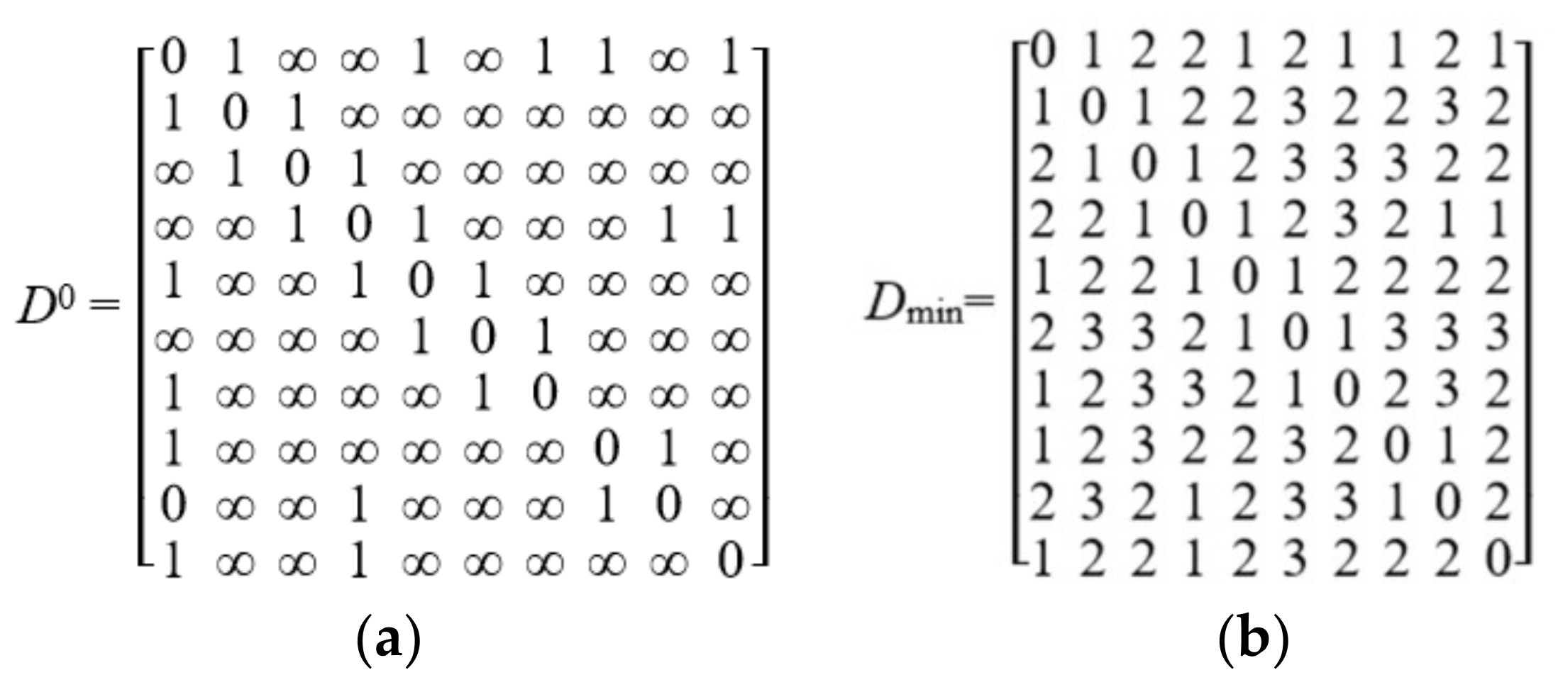
The minimum distance matrix of a topological graph is denoted as Dmin = [Di,j]n×n, where Di,j is the minimum distance between vertices i and j. First, we define an initial distance matrix D0 as shown in Equation (4), where wi,j is the weight of edge ei,j. For example, the initial distance matrix of Figure 6a is shown in Figure 7a.
An array of recursive matrices, D1 … Dk … Dn where , can be computed in turn according to the Floyd algorithm shown in Equation (5). The n-th recursive matrix is the minimum distance matrix Dmin. According to Equation (5), the recursive matrix D10, i.e., Dmin, of Figure 6a is obtained and shown in Figure 7. As an example, element D1,3 in Figure 7b is equal to 2, meaning that the minimum distance between vertices 1 and 3 in Figure 6a is 2. This value corresponds to path 1–2–3 which has two 1-weight edges in Figure 6a.
3.3. Moment of a Link
The moment of a force about a point is defined as the product of the force and the perpendicular distance, i.e., the minimum distance from the point to the force. Analogous to this concept, the moment of link i about link j in a kinematic chain is the product of the weight of link i and the minimum distance from link i to link j. For example, the weight of link 1 in Figure 6a is 5, and the minimum distance from link 1 to link 3 is 2; hence, the moment of link 1 about link 3 is M1,3 = 5 × 2 = 10.
3.4. Moment Matrix
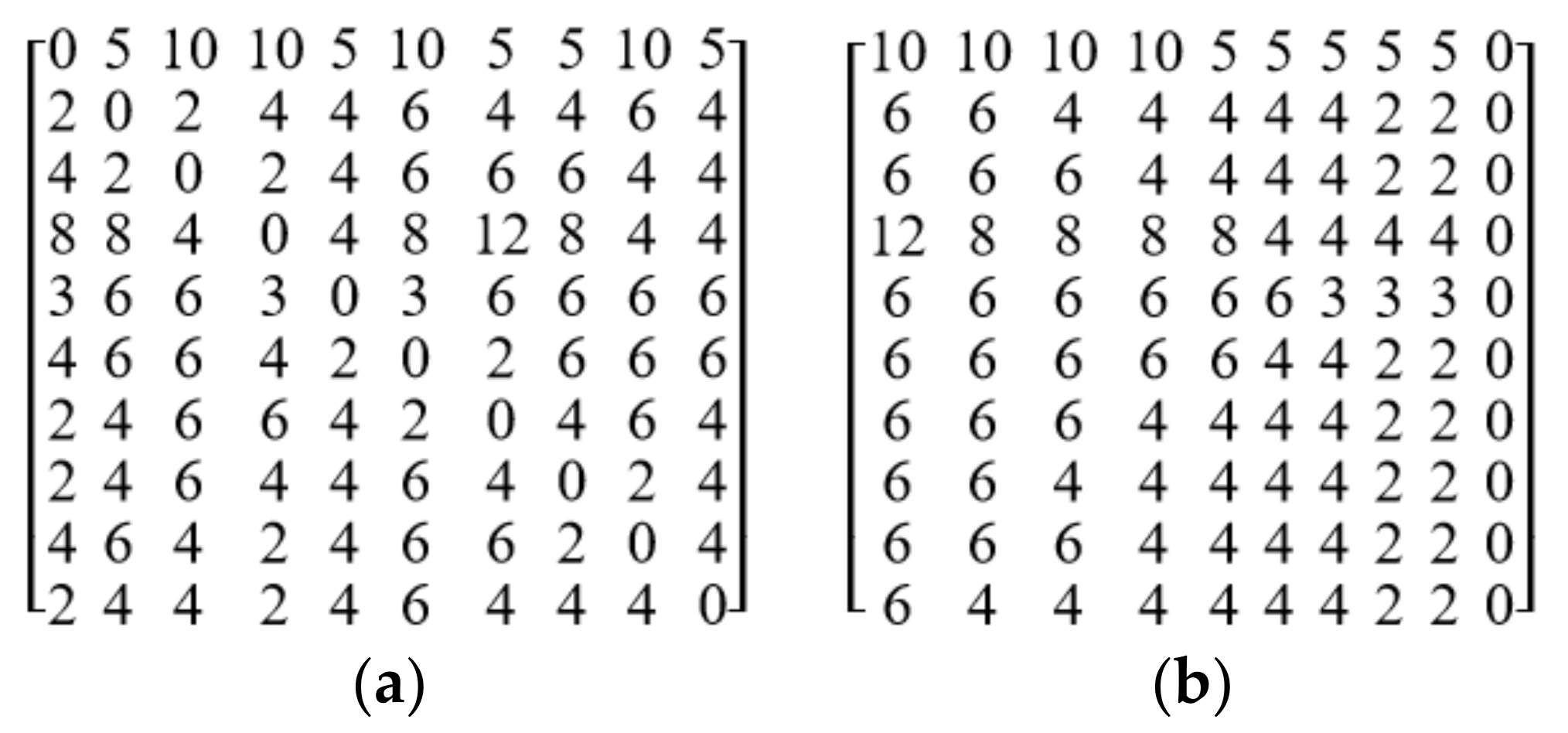
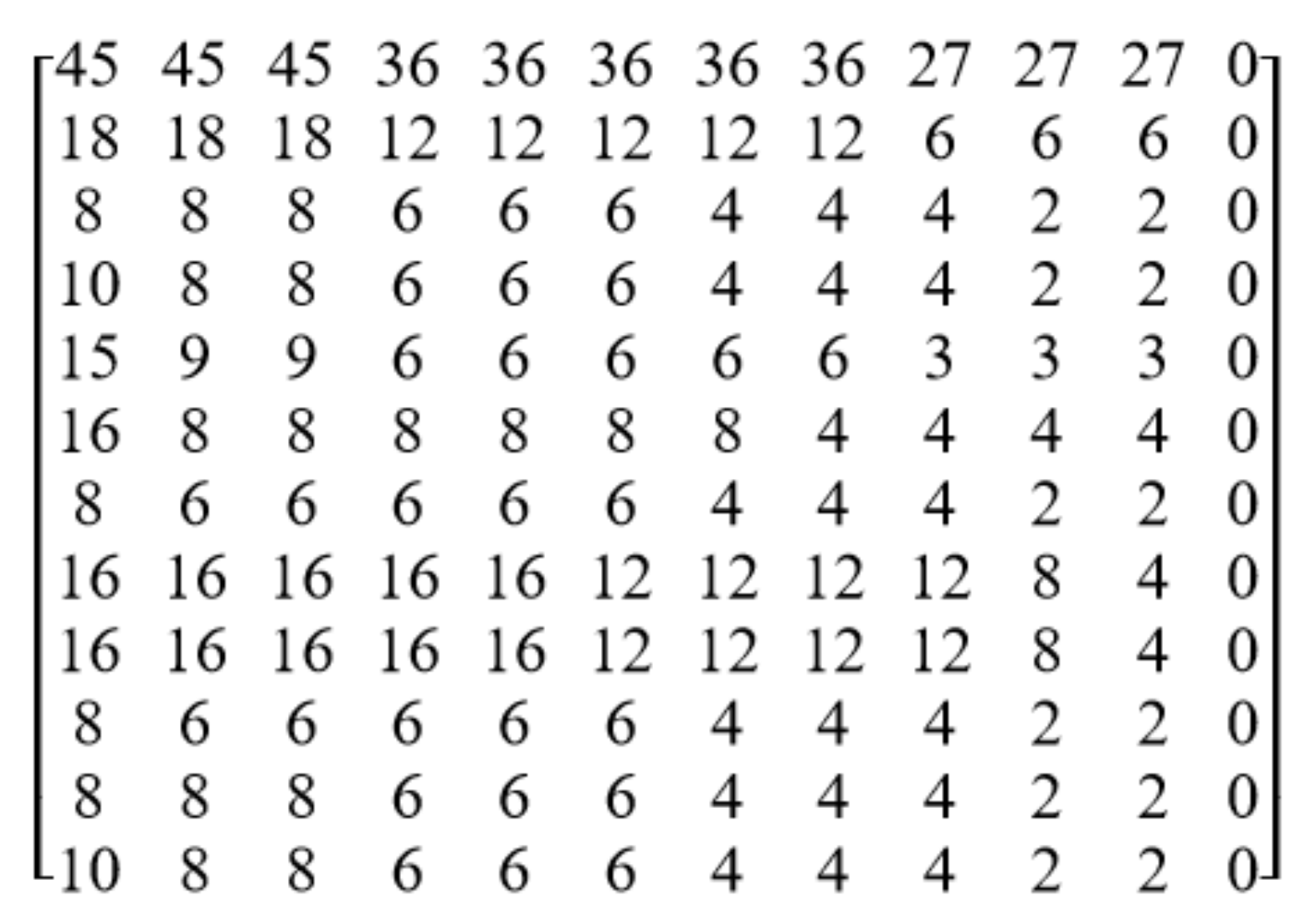
The moment matrix of a kinematic chain is denoted as M = [Mi,j]n×n, where Mi,j is the moment of link i about link j. The rearranged moment matrix is acquired by permuting the elements in each row of the moment matrix in descending order. For example, the moment matrix of Figure 6a is shown in Figure 8a, and the corresponding rearranged moment matrix is shown in Figure 8b. In the following, we will present the symmetry detection method based on the rearranged moment matrix.
4. Unique Numerical Code for Symmetry Detection
The symmetry detection method is desired to be reliable. Only in this way can isomorphism be precisely eliminated when synthesizing and designing mechanisms. We propose an algorithm to generate the unique numerical code of each link based on the rearranged moment matrix. The derived unique numerical code can be used to precisely detect symmetric links of kinematic chains.
4.1. Link Group
If the elements in row i of the rearranged moment matrix are equal to those elements in row j, links i and j are put in the same group. For example, both the elements in rows 2 and 8 in Figure 8b are (6, 6, 4, 4, 4, 4, 4, 2, 2, 0), hence, links 2 and 8 are put in the same group; similarly, the elements in rows 3, 7, and 9 are (6, 6, 6, 4, 4, 4, 4, 2, 2, 0), hence, links 3, 7, and 9 are put in the same group. Finally, the link groups (LGs) of Figure 6a are acquired as LGs = {1}, {2, 8}, {3, 7, 9}, {4}, {5}, {6}, {10}. The links in different groups are obviously nonsymmetric because they have the different topological characteristics. It is necessary to further confirm whether the links in the same group are symmetric. In the present example, it is necessary to confirm whether links 2 and 8 in Figure 6a are symmetric, as well as links 3, 7, and 9.
4.2. Unique Numerical Code
In order to generate the unique numerical code of link i, link i is extracted as the first group to obtain new link groups, denoted as LGsi. For the new link groups LGsi, links in the same group are permuted in all possible ways to derive new relabeling of the kinematic chain. The numerical code of each relabeling is formed by concatenating the upper triangular elements of the associated adjacency matrix row-by-row. The maximum numerical code is defined as the unique numerical code of link i, denoted as the UN-codei. Symmetric links of a kinematic chain can be precisely detected by comparing their unique numerical codes. If UN-codei = UN-codej, links i and j are symmetric; otherwise, they are nonsymmetric.
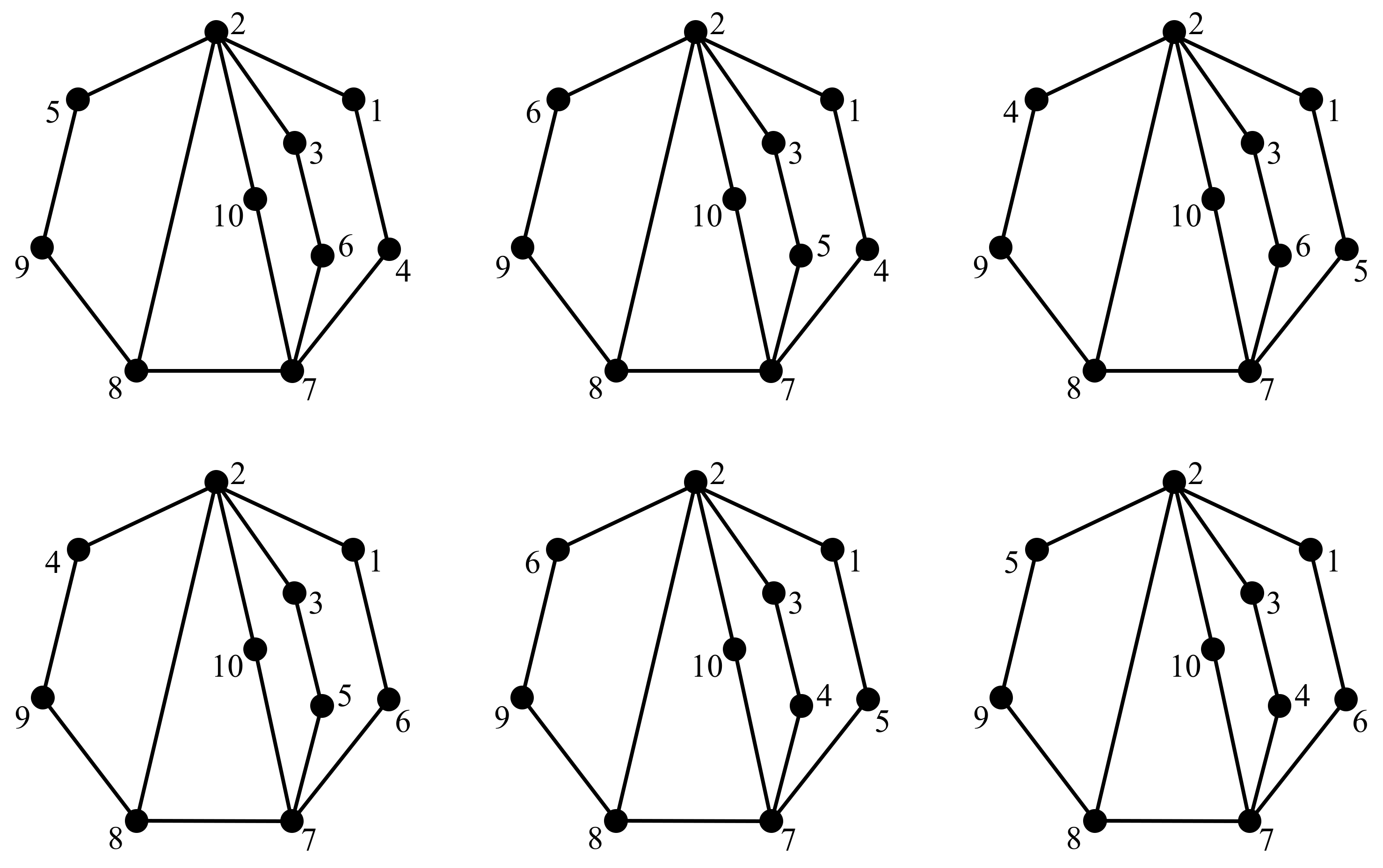
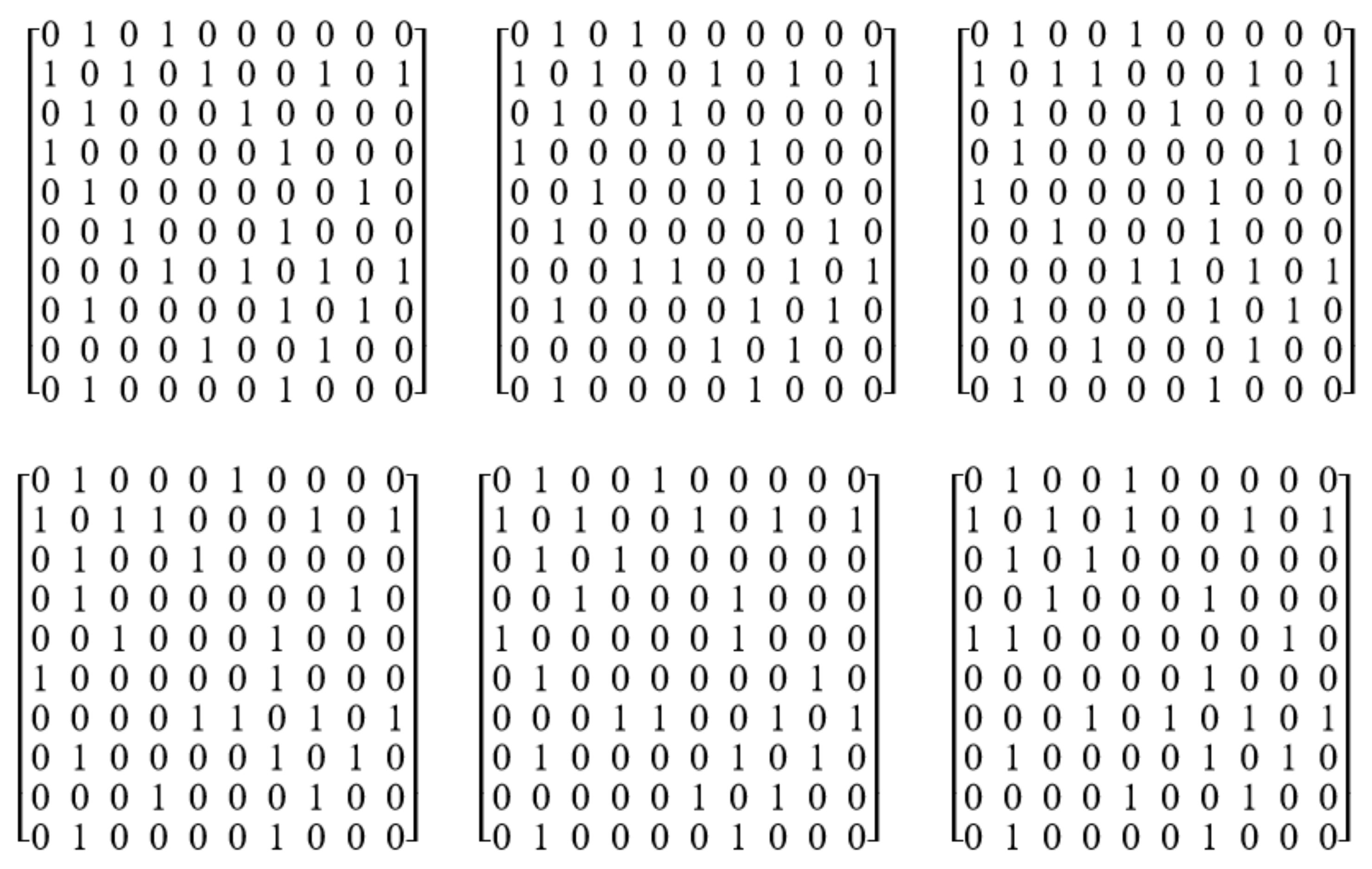
The vertex group LGs of Figure 6a are listed in the first row of Table 1. Taking link 2 for instance, let us discuss how to obtain the unique numerical code of link 2, namely UN-code2. Link 2 is extracted as the first group and the derived new link groups LGs2 are {2}, {1}, {8}, {3, 7, 9}, {4}, {5}, {6}, {10}, as listed in the second row of Table 1. There are six permutations in group {3, 7, 9}, hence, there are six ways to relabel Figure 6a, as listed in Table 2. The six ways of relabeling Figure 6a are shown in Figure 9. For example, for the first permutation, links 2, 1, 8, 3, 7, 9, 4, 5, 6, 10 of Figure 6a are relabeled as 1–10, respectively, and the corresponding relabeled graph is shown in the first graph in Figure 9; for the second permutation, links 2, 1, 8, 3, 9, 7, 4, 5, 6, 10 are relabeled as 1–10, respectively, and the corresponding relabeled graph is shown in the second graph in Figure 9. The adjacency matrices of the graphs in Figure 9 are shown in Figure 10. For example, by concatenating the upper triangular elements of the first graph in Figure 10, the numerical code of the first graph in Figure 9 is acquired as C1 = 101000000-10100101-0010000-001000-00010-1000-101-10-0. The numerical codes of the graphs in Figure 9 are acquired and listed in Table 1. Among the six numerical codes C1–C6, the largest one is C1; hence, C1 is determined as the unique numerical code of link 2, namely UN-code2 = 101000000-10100101-0010000-001000-00010-1000-101-10-0. In the same way, the unique numerical code of link 8 is UN-code8 = 101000000-10100101-0010000-001000-00010-1000-101-10-0. Due to UN-code2 = UN-code8, we can conclude that links 2 and 8 in Figure 6a are symmetric.
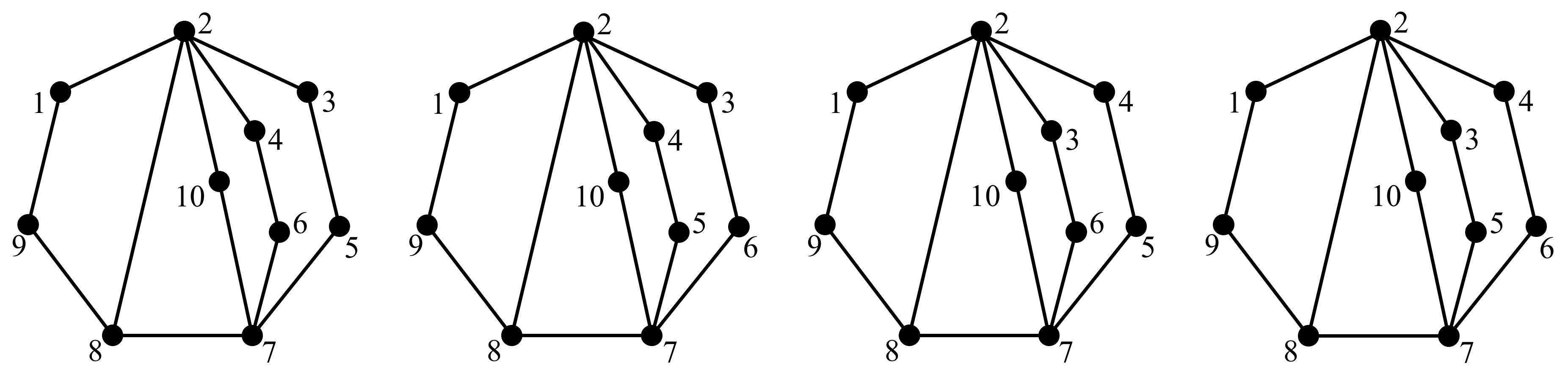
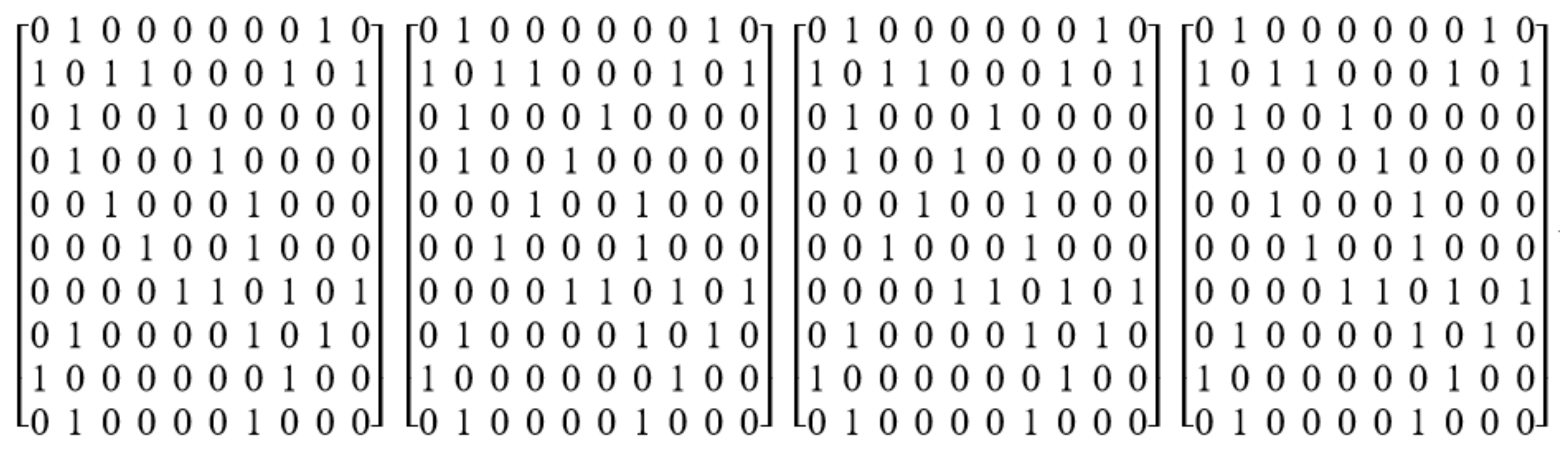
As another example, let us discuss how to obtain the unique numerical code of link 7, namely UN-code7. Link 7 is extracted as the first group and the derived new link groups LGs7 are {7}, {1}, {2, 8}, {3, 9}, {4}, {5}, {6}, {10}, as listed in the second row of Table 3. There are two permutations in group {2, 8} and two permutations in group {3, 9}, hence there are four ways to relabel Figure 6a, as listed in Table 4. The four ways to relabel Figure 6a are shown in Figure 11. For example, for the first permutation, links 7, 1, 2, 8, 3, 9, 4, 5, 6, 10 of Figure 6a are relabeled as 1–10, respectively, and the corresponding relabeled graph is shown in the first graph in Figure 11. The adjacency matrices of the graphs in Figure 11 are shown in Figure 12. For example, by concatenating the upper triangular elements of the first graph in Figure 12, the numerical code of the first graph in Figure 11 is acquired as C1 = 100000010-11000101-010 0000-010000-01000-1000-101-10-0. The numerical codes of the graphs in Figure 11 are acquired and listed in Table 3. Among the four numerical codes C1–C4, both C1 and C4 have the largest value; hence, C1 (or C4) is determined as the unique numerical code of link 7, namely UN-code7 = 100000010-11000101-0100000-010000-01000-1000-101-10-0. In the same way, we can get that both UN-code3 and UN-code9 are equal to 010001000-11100101-0000000-010000-00010-1000-101-10-0. Due to UN-code3 = UN-code9 and UN-code7 ≠ UN-code3, we can conclude that links 3 and 9 in Figure 6a are symmetric, whereas link 7 is not symmetric with links 3 and 9.
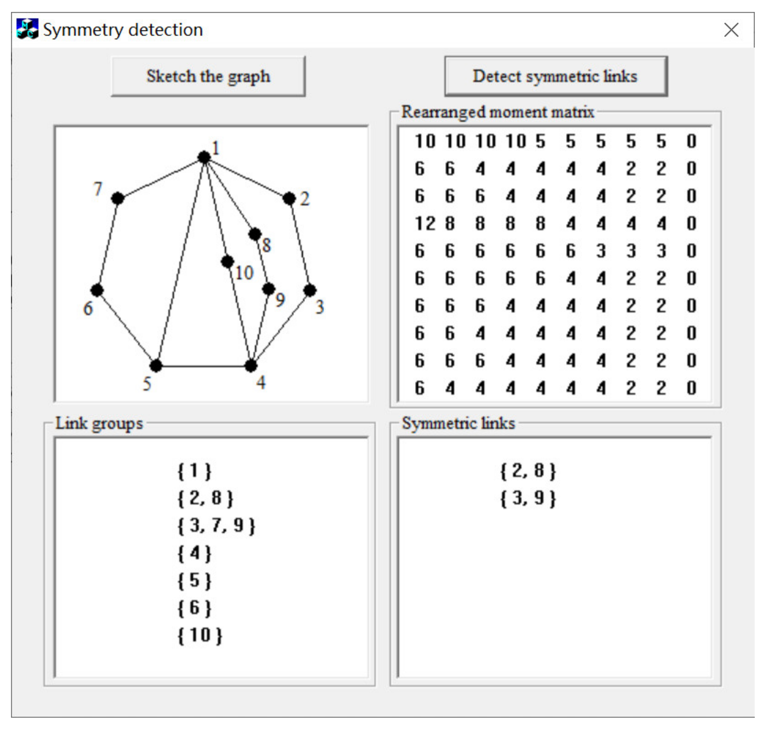
We have developed the symmetry detection software based on the C++ computer programming language, and the software interface is developed based on MFC (Microsoft Foundation Classes). Our present symmetry detection method is fully automatic, and the adjacency matrix is the only input data needed to develop the computer software. Upper triangular elements of the adjacency matrix are stored in a txt file. By reading the adjacency matrix, the topological graph can be automatically sketched, and the detection result can be automatically generated and displayed on the software interface. For example, the automatic detection of symmetric links of the kinematic chain in Figure 6a is shown in Figure 13. In the window “symmetric links”, groups {2, 8} and {3, 9} mean that links 2 and 8 are symmetric, and links 3 and 9 are also symmetric.
5. Applications in Various Kinematic Chains and Mechanisms
The first major advantage of our symmetry detection method is reliability. The unique numerical code and the associated link have a strict one-to-one correspondence; hence, the derived unique numerical codes can be used to precisely detect the symmetric links of kinematic chains and mechanisms. The second major advantage of our method is versatility. By giving different weights to different kinds of edges in the topological graph, our method possesses the ability to deal with all kinds of plane kinematic chains and mechanisms.
5.1. Synthesis of Kinematic Chain Inversions
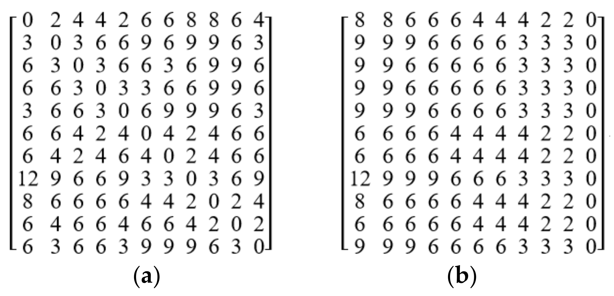
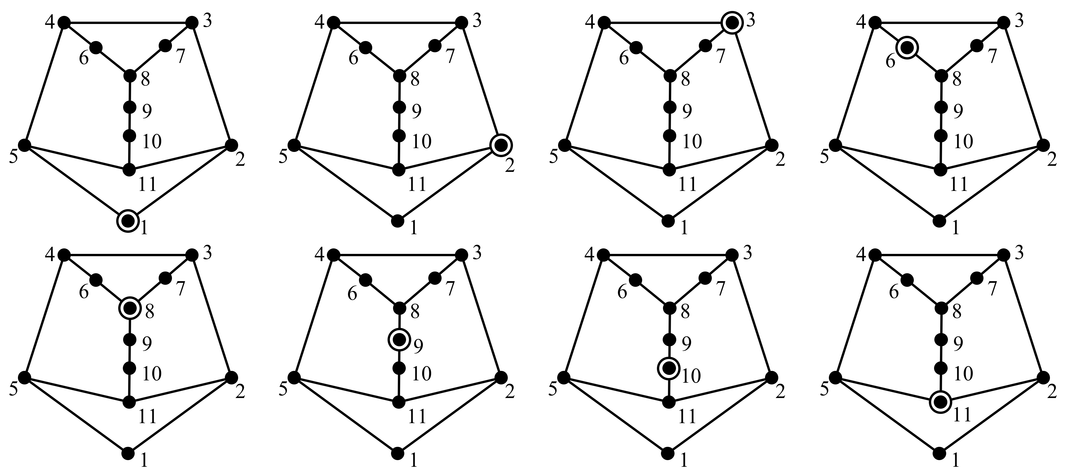
A plane kinematic chain inversion refers to as a plane kinematic chain with one link fixed (assigned as the ground link). Symmetric links should not be assigned as ground links to avoid isomorphic inversions. The synthesis of inversions from the 11-link two-DOF kinematic chain in Figure 3a is discussed as follows. The moment matrix and rearranged moment matrix of Figure 3a are shown in Figure 14a and b, respectively. According to Figure 14b, the link groups LGs of Figure 3a are acquired as {1}, {2, 5, 11}, {3, 4}, {6, 7}, {8}, {9}, {10}. The unique numerical codes of the links in the same groups are listed in Table 5. We can conclude that links 2 and 5, links 3 and 4, and links 6 and 7 are symmetric, respectively. The inversion whose ground link is 5 should be excluded because it is isomorphic with the inversion whose ground link is 2. Similarly, the inversions whose ground links are 4 and 7 should be also excluded. Therefore, eight nonisomorphic inversions can be synthesized from Figure 3a, as shown in Figure 15, where a ground link is marked with a small circle. Finally, from the atlas of 753 11-link 2-DOF plane nonfractionated kinematic chains, we have automatically synthesized 7156 nonisomorphic inversions. Our method is also applied to synthesize different kinds of inversions with 8–12 links, and the synthesis results are listed in Table 6.
5.2. Synthesis of Assur Groups
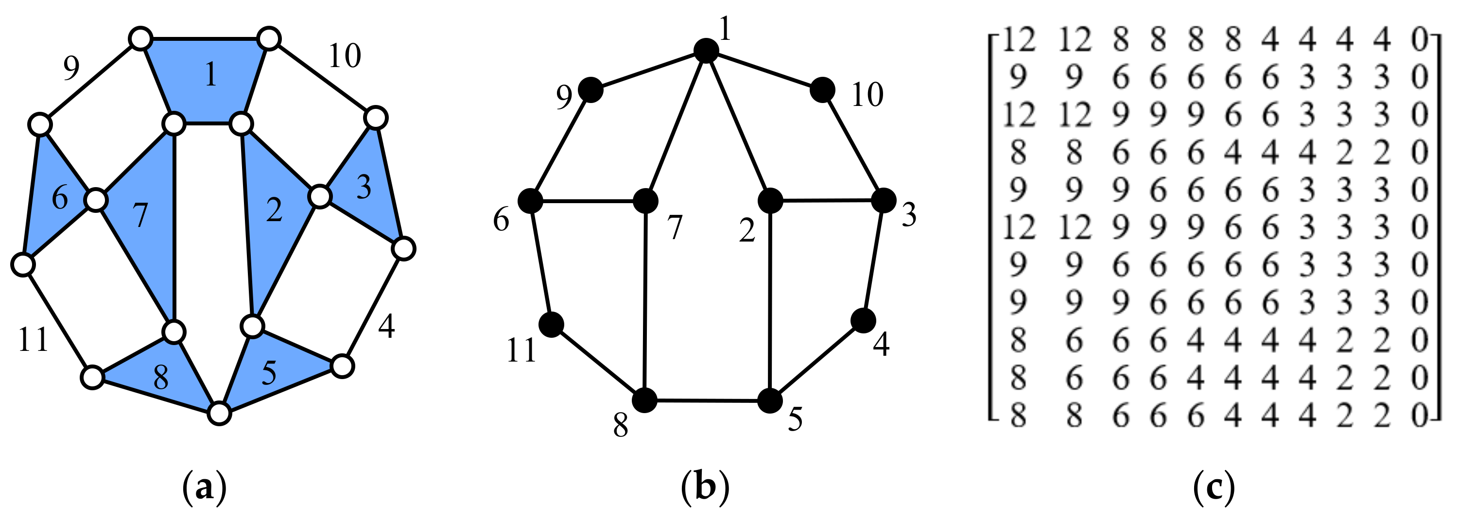
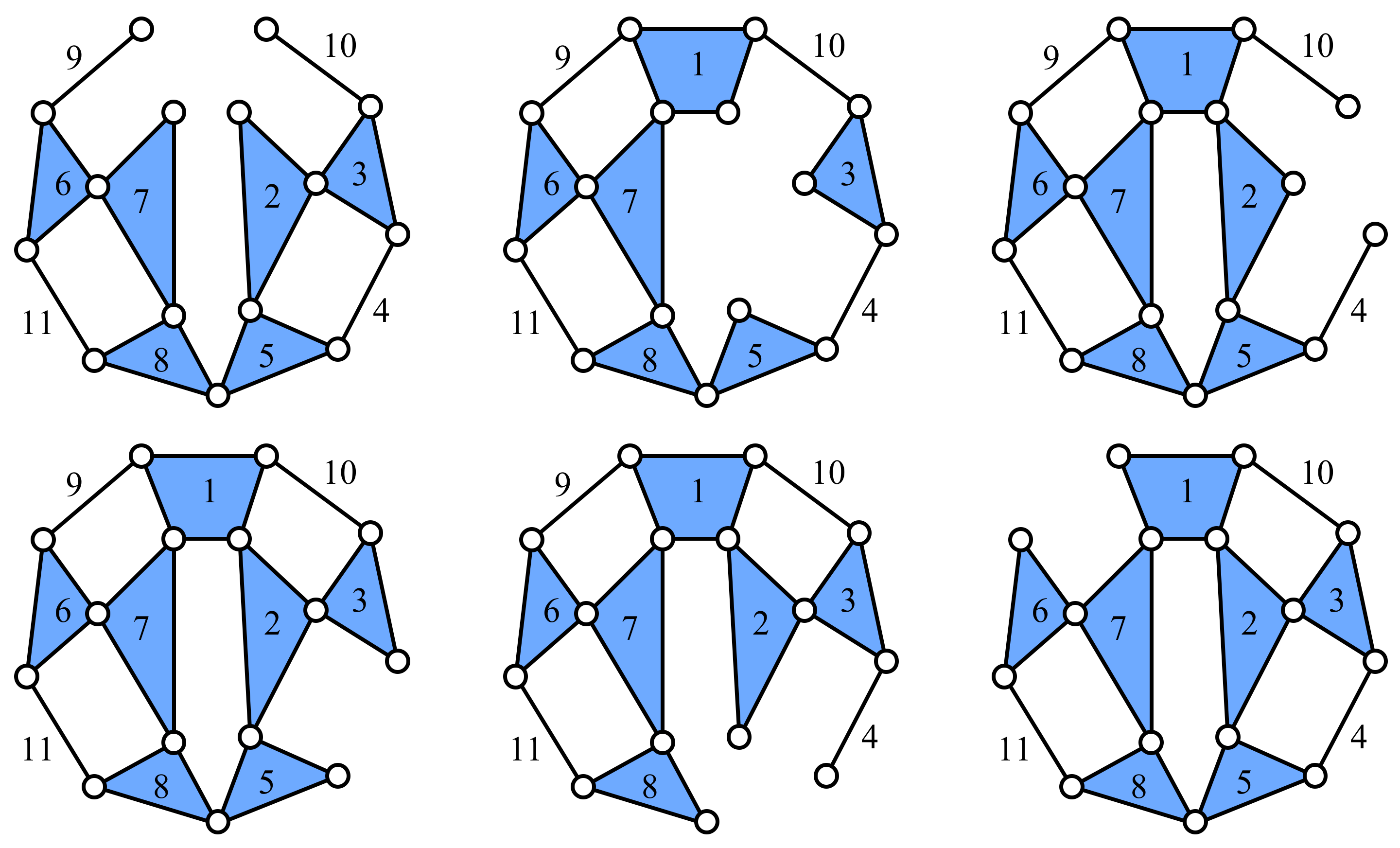
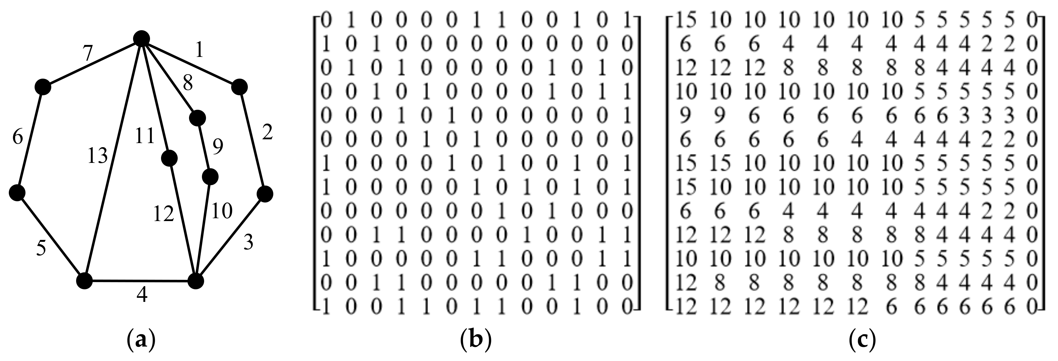
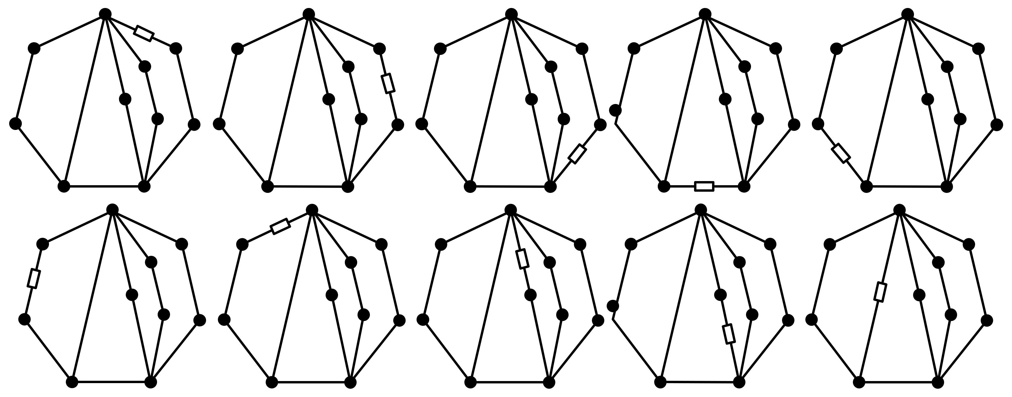
A Baranov truss is a plane zero-DOF kinematic chain without any rigid subchain. An Assur Group is an open zero-DOF kinematic chain which can be obtained by removing one link of a Baranov truss. If symmetric links of a Baranov truss are removed, the derived Assur Groups are isomorphic. For example, Figure 16a shows an 11-link Baranov truss, Figure 16b is the corresponding topological graph, and Figure 16c is its rearranged moment matrix. According to Figure 16c, the link groups LGs of Figure 16a are acquired as {1}, {2, 7}, {3, 6}, {4, 11}, {5, 8}, {9, 10}. The unique numerical codes of the links in the same groups are listed in Table 7. Symmetric links of Figure 16a can be acquired as {2, 7}, {3, 6}, {4, 11}, {5, 8}, {9, 10}. For the purpose of avoiding isomorphism, only one link in each group of symmetric links is removed to generate Assur Groups. Therefore, six nonisomorphic Assur Groups can be synthesized from Figure 16a, which are generated by removing links 1, 2, 3, 4, 5, and 9, respectively, as shown in Figure 17.
5.3. Synthesis of Multiple Joint Kinematic Chains
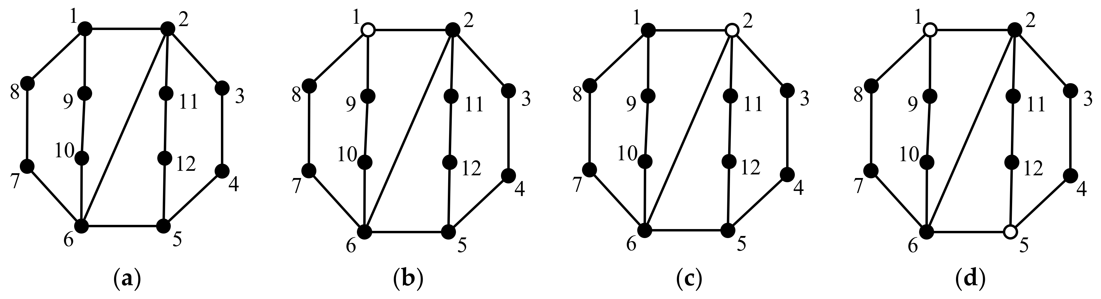
An (N-1)-link (F-1)-DOF kinematic chain with one multiple joint can be generated from an N-link F-DOF simple joint kinematic chain by transforming a multiple link into a multiple joint. A 12-link three-DOF simple joint kinematic chain is shown in Figure 18a. Using our method, we can conclude that multiple links 1 and 5 are symmetric, and multiple links 2 and 6 are symmetric. Symmetric multiple links should not be transformed into multiple joints for the purpose of avoiding isomorphism; hence, two 11-link two-DOF kinematic chains with one multiple joint can be synthesized from Figure 18a, as shown in Figure 18b,c. Furthermore, an (N-1)-link (F-1)-DOF kinematic chain with two multiple joints can be generated from an N-link F-DOF kinematic chain with one multiple joint by transforming a multiple link into a multiple joint. The rearranged moment matrix of Figure 18b is shown in Figure 19. According to Figure 19, multiple links 2, 5, and 6 in Figure 18b are nonsymmetric. However, due to the constraint of rigid subchain, only multiple link 5 is allowed to be transformed into multiple joint, and the derived 10-link one-DOF kinematic chain with two multiple joints is shown in Figure 18d. Due to the constraint of rigid subchain, no kinematic chain with two multiple joints can be synthesized from Figure 18c.
Our method is also applied to the counterexamples in Ref. [29]. For the multiple joint kinematic chain, numbered as No. 12 in Appendix C of Ref. [29], we find that there are no symmetric vertices; for the multiple joint kinematic chain, numbered as No. 18 in Appendix C of Ref. [29], we find that vertices 1 and 3 are symmetric, vertices 4, 8, 9, and 10 are symmetric, and vertices 5 and 7 are symmetric. Our conclusion can be verified by Ref. [28], whereas the method in Ref. [29] fails to correctly detect symmetric vertices in these two kinematic chains.
5.4. Synthesis of Kinematic Chains with Prismatic Pairs
Kinematic chains with prismatic pairs can be synthesized by transforming the revolute pairs into prismatic pairs. This process involves the detection of symmetric edges, i.e., symmetric kinematic pairs. Our method can be used to detect symmetric edges based on the edge–edge adjacency matrix. For example, the kinematic chain in Figure 6a is resketched as Figure 20a and its edges are numbered. The corresponding edge–edge adjacency matrix and rearranged moment matrix are shown in Figure 20b and c, respectively. According to Figure 20c, the edge groups of Figure 20a are acquired as {1, 8}, {2, 9}, {3, 10}, {4, 11}. Finally, edges 1 and 8, edges 2 and 9, and edges 3 and 10, respectively, are determined as being symmetric according to their unique numerical codes. Hence, 10 nonisomorphic kinematic chains with one prismatic pair can be synthesized from Figure 20a, as shown in Figure 21. A prismatic pair is denoted by an edge marked with a small rectangle.
5.5. Topological Synthesis of Planetary Gear Mechanisms of Powertrains
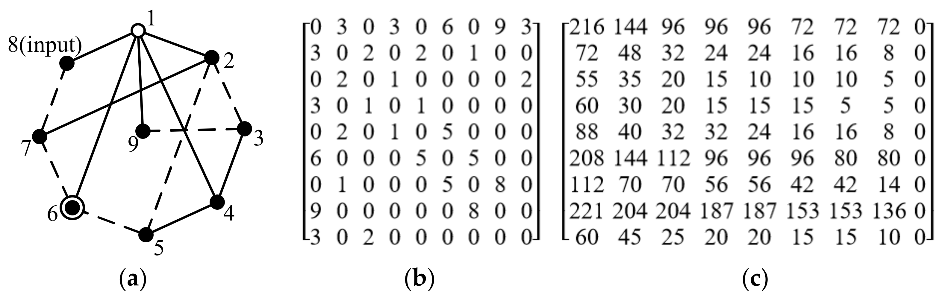
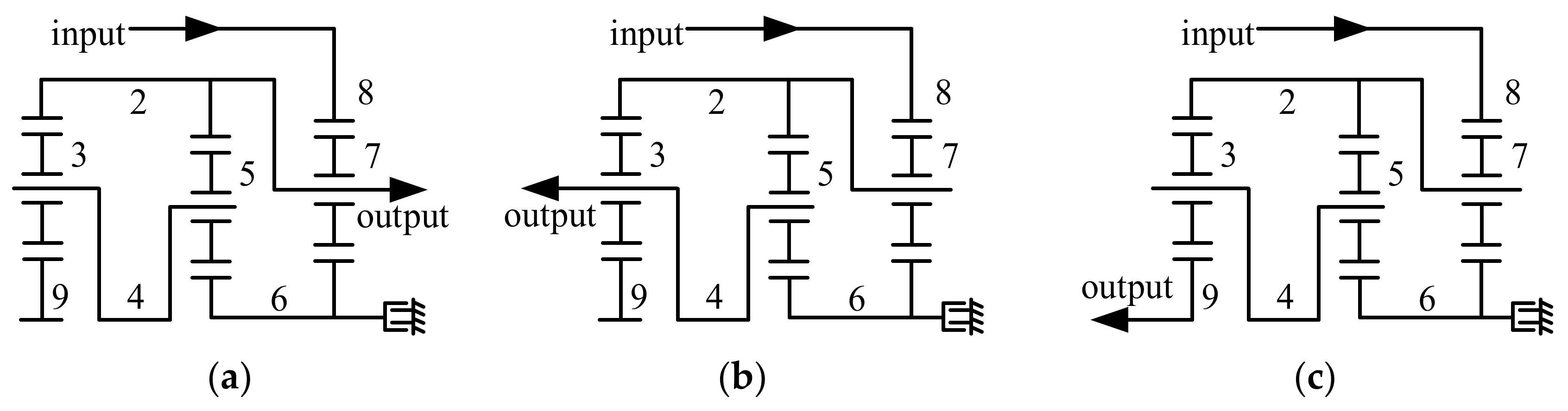
Planetary gear mechanisms are the core mechanism of powertrains and transmission systems. The topological synthesis of planetary gear mechanisms is achieved by assigning ground links, input links, and output links in the planetary gear trains to obtain nonisomorphic mechanisms. Taking Figure 4b, for instance, central links 2, 4, 6, 8, and 9 are detected as being nonsymmetric according to the rearranged moment matrix; hence, all the five links can be assigned as the ground link. As an example, the mechanism whose ground link is link 6 is shown in Figure 22a, and its adjacency matrix is shown in Figure 22b. In order to distinguish different kinds of edges, the weight of edges incident with link 6 is increased by 3. For example, the weight of edge e1,6 in Figure 4b is 3, while in Figure 22a its weight is 3 + 3 = 6. The adjacency matrix of Figure 22a is shown in Figure 22b, and the corresponding rearranged moment matrix is shown in Figure 22c, based on which central links 2, 4, 8, and 9 are detected as being nonsymmetric. All these four links can be assigned as input links. As an example, the mechanism whose input link is link 8 is shown in Figure 23a, and its adjacency matrix is shown in Figure 23b, where the weight of edges incident with link 8 is increased by 6. According to the rearranged moment matrix in Figure 23c, central links 2, 4, and 9 are detected as being nonsymmetric. The derived nonisomorphic planetary gear mechanisms whose output links are link 2, 4, and 9 are shown in Figure 24a–c, respectively.
Some other examples of symmetry detection of 12-link three-DOF simple joint kinematic chains, 10-link one-DOF multiple joint kinematic chains, and 8-link two-DOF planetary gear trains are shown in Table A1 in Appendix A, Table A2 in Appendix B and Table A3 in Appendix C, respectively. All the topological graphs and symmetric vertices are automatically generated via our computer software. The topological graphs and groups of symmetric vertices shown in Appendix A, Appendix B and Appendix C are screenshots taken from the software interface.
6. Conclusions
In this paper, we present a fully automatic and reliable method for detecting the symmetry of plane kinematic chains and extend this method to the symmetry detection and the topological design of mechanisms of powertrains. The topological model and adjacency matrix are introduced to represent various kinds of plane kinematic chains. The moment matrix of the kinematic chain is established to obtain link groups, based on which we propose an algorithm to generate the unique numerical code of each link, and precisely detect the symmetric links of kinematic chains.
We have developed the symmetry detection software based on the C++ computer programming language, and the software interface is developed based on MFC. The present symmetry detection method is fully automatic, and the adjacency matrix is the only input data needed to develop the computer software. The upper triangular elements of the adjacency matrix are stored in a txt file. By reading the adjacency matrix, the corresponding topological graph can be automatically sketched, and the moment matrix and symmetry detection results can be automatically generated and displayed on the software interface.
Our method can be used to detect symmetric links of all kinds of plane kinematic chains and mechanisms, and it can be also applied to detect symmetric kinematic pairs based on the edge–edge adjacency matrix. This method is applied to synthesize different kinds of plane kinematic chains and mechanisms, which proves the versatility and reliability of the method.
The present study can be applied to avoid the generation of isomorphism and is helpful for improving the design efficiency of mechanisms of powertrains and other mechanical devices. The future work is to establish a mechanism evaluation method to design novel mechanisms of powertrains with the best performance based on the atlas of synthesized planetary gear mechanisms.
Author Contributions
Conceptualization, W.Y.; methodology, W.Y.; software, W.Y.; validation, W.Y.; formal analysis, W.Y.; investigation, W.Y.; resources, W.Y.; data curation, W.Y.; writing—original draft preparation, W.Y.; writing—review and editing, C.L.; visualization, C.L.; supervision, C.L.; project administration, C.L.; funding acquisition, W.Y. and C.L. All authors have read and agreed to the published version of the manuscript.
Funding
This research was funded by the Fundamental Research Funds for the Central Universities, China University of Geosciences (Wuhan) (no. 162301212701) and the National Natural Science Foundation of China (no. 42002310). The APC was funded by the Fundamental Research Funds for the Central Universities, China University of Geosciences (Wuhan) (no. 162301212701).
Institutional Review Board Statement
Not applicable.
Informed Consent Statement
Not applicable.
Data Availability Statement
Not applicable.
Acknowledgments
The authors are grateful to the projects supported by the Fundamental Research Funds for the Central Universities, China University of Geosciences (Wuhan) (no. 162301212701) and the National Natural Science Foundation of China (no. 42002310).
Conflicts of Interest
The authors declared no potential conflict of interest with respect to the research, authorship, and publication of this article.
Appendix A

Table A1.
Symmetry detection of 12-link 3-DOF simple joint kinematic chains.
| Graphs | Groups of Symmetric Vertices | Graphs | Groups of Symmetric Vertices |
|---|---|---|---|
 |  |  |  |
 |  |  | None |
 | None |  |  |
 | None |  | None |
 | None |  |  |
 |  |  |  |
 |  |  | None |
 |  |  |  |
Appendix B
Table A2.
Symmetry detection of 10-link 1-DOF kinematic chains with two multiple joints.
| Graphs | Groups of Symmetric Vertices | Graphs | Groups of Symmetric Vertices |
|---|---|---|---|
 | None |  |  |
 |  |  | None |
 |  |  |  |
 |  |  |  |
Appendix C
Table A3.
Symmetry detection of 8-link 2-DOF planetary gear trains.
| Graphs | Groups of Symmetric Vertices | Graphs | Groups of Symmetric Vertices |
|---|---|---|---|
 | None |  |  |
 | None |  |  |
 |  |  |  |
 |  |  | None |
References
- Zhuang, W.C.; Zhang, X.W.; Ding, Y.; Wang, L.M.; Hu, X.S. Comparison of multi-mode hybrid powertrains with multiple planetary gears. Appl. Energy 2016, 178, 624–632. [Google Scholar] [CrossRef]
- Pei, H.X.; Hu, X.S.; Yang, Y.L.; Tang, X.L.; Hou, C.; Cao, P.D. Configuration optimization for improving fuel efficiency of power split hybrid powertrains with a single planetary gear. Appl. Energy 2018, 214, 103–116. [Google Scholar] [CrossRef]
- Ho, T.T.; Hwang, S.J. Configuration synthesis of novel hybrid transmission systems using a combination of a Ravigneaux gear train and a simple planetary gear train. Energies 2020, 13, 2333. [Google Scholar] [CrossRef]
- Mruthyunjaya, T.S. Kinematic structure of mechanisms revisited. Mech. Mach. Theory 2003, 38, 279–320. [Google Scholar] [CrossRef]
- Yan, H.S.; Chiu, Y.T. On the number synthesis of kinematic chains. Mech. Mach. Theory 2015, 89, 128–144. [Google Scholar] [CrossRef]
- Yan, H.S.; Hwang, Y.W. The specialization of mechanisms. Mech. Mach. Theory 1991, 26, 541–551. [Google Scholar] [CrossRef]
- Wang, Y.X.; Yan, H.S. Computerized rules-based regeneration method for conceptual design of mechanisms. Mech. Mach. Theory 2002, 37, 833–849. [Google Scholar] [CrossRef]
- Mruthyunjaya, T.S. A computerized methodology for structural synthesis of kinematic chains: Part 2—Application to several fully or partially known cases. Mech. Mach. Theory 1984, 19, 497–505. [Google Scholar] [CrossRef]
- Mruthyunjaya, T.S. A computerized methodology for structural synthesis of kinematic chains: Part 3—Application to the new case of 10-link, three-freedom chains. Mech. Mach. Theory 1984, 19, 507–530. [Google Scholar] [CrossRef]
- Mruthyunjaya, T.S.; Balasubramanian, H.R. In quest of a reliable and efficient computational test for detection of isomorphism in kinematic chains. Mech. Mach. Theory 1987, 22, 131–139. [Google Scholar] [CrossRef]
- Rao, A.C.; Varada Raju, D. Application of the hamming number technique to detect isomorphism among kinematic chains and inversions. Mech. Mach. Theory 1991, 26, 55–75. [Google Scholar] [CrossRef]
- Rao, A.C. Hamming number technique—I. Further applications. Mech. Mach. Theory 1997, 32, 477–488. [Google Scholar] [CrossRef]
- Yan, H.S.; Hung, C.C. Identifying and counting the number of mechanisms from kinematic chains subject to design constraints. ASME J. Mech. Des. 2006, 128, 1177–1182. [Google Scholar] [CrossRef]
- Hung, C.C.; Yan, H.S.; Pennock, G.R. A procedure to count the number of planar mechanisms subject to design constraints from kinematic chains. Mech. Mach. Theory 2008, 43, 676–694. [Google Scholar] [CrossRef]
- Kim, J.T.; Kwak, B.M. An algorithm of topological ordering for unique representation of graphs. ASME J. Mech. Des. 1992, 114, 103–108. [Google Scholar] [CrossRef]
- Chu, J.K.; Cao, W.Q. Identification of isomorphism among kinematic chains and inversions using link’s adjacent chain table. Mech. Mach. Theory 1994, 29, 53–58. [Google Scholar]
- Yadav, J.N.; Pratap, C.R.; Agrawal, V.P. Mechanisms of a kinematic chain and the degree of structural similarity based on the concept of link-path code. Mech. Mach. Theory 1996, 31, 865–871. [Google Scholar] [CrossRef]
- Yadav, J.N.; Pratap, C.R.; Agrawal, V.P. Computer aided detection of isomorphism among kinematic chains and mechanisms using the concept of modified distance. Mech. Mach. Theory 1996, 31, 439–444. [Google Scholar] [CrossRef]
- Tuttle, E.R.; Peterson, S.W.; Titus, J.E. Further applications of group theory to the enumeration and structural analysis of basic kinematic chains. ASME J. Mech. Transm. Autom. Des. 1989, 111, 494–497. [Google Scholar] [CrossRef]
- Tuttle, E. Generation of planar kinematic chains. Mech. Mach. Theory 1996, 31, 729–748. [Google Scholar] [CrossRef]
- Rao, A.C.; Prasad Raju Pathapati, V.V.N.R. Loop based detection of isomorphism among chains, inversions and type of freedom in multi degree of freedom chain. ASME J. Mech. Des. 2000, 122, 31–42. [Google Scholar] [CrossRef]
- Kuo, C.H.; Shih, C.J. Computational identification of link adjacency and joint incidence in kinematic chains and mechanisms. ASME J. Mech. Design 2008, 130, 084501. [Google Scholar] [CrossRef]
- Simoni, R.; Carboni, A.P.; Martins, D. Enumeration of kinematic chains and mechanisms. Proc. Inst. Mech. Eng. Part C J. Mech. Eng. Sci. 2009, 223, 1017–1024. [Google Scholar] [CrossRef]
- Dargar, A.; Hasan, A.; Khan, R.A. Some new codes for isomorphism identification among kinematic chains and their inversions. Int. J. Mech. Robot. Syst. 2013, 1, 49–67. [Google Scholar] [CrossRef]
- Nie, S.H.; Li, B.; Qiu, A.H.; Gong, S.G. Kinematic configuration analysis of planar mechanisms based on basic kinematic chains. Mech. Mach Theory 2011, 46, 1327–1334. [Google Scholar] [CrossRef]
- Nie, S.H.; Liao, A.H.; Qiu, A.H.; Gong, S.G. Addition method with 2 links and 3 pairs of type synthesis to planar closed kinematic chains. Mech. Mach. Theory 2012, 58, 179–191. [Google Scholar] [CrossRef]
- Yang, W.J.; Ding, H.F.; Lai, X.Z.; Wu, M. Automatic synthesis of planar simple joint mechanisms with up to 19 links. Mech. Mach. Theory 2017, 113, 193–207. [Google Scholar] [CrossRef]
- Deng, T.; Xu, H.; Wu, C.J.; Zhang, L.; Gan, Z.H. Topological symmetry identification of kinematic chains based on topological index. Mech. Mach. Theory 2020, 154, 104099. [Google Scholar] [CrossRef]
- Sun, L.; Cui, R.J.; Ye, Z.Z.; Zhou, Y.Z.; Xu, Y.D.; Wu, C.Y. Similarity recognition and isomorphism identification of planar kinematic chains. Mech. Mach. Theory 2020, 145, 103678. [Google Scholar] [CrossRef]
- Cui, R.J.; Ye, Z.Z.; Xu, S.F.; Wu, C.Y.; Sun, L. Synthesis of planar kinematic chains with prismatic pairs based on a similarity recognition algorithm. ASME J. Mech. Robot. 2021, 13, 1–13. [Google Scholar] [CrossRef]
- Sun, L.; Ye, Z.Z.; Cui, R.J.; Huang, X.W.; Wu, C.Y. Eliminating isomorphism identification method for synthesizing nonfractionated kinematic chains based on graph similarity. Mech. Mach. Theory 2022, 167, 104500. [Google Scholar] [CrossRef]
Figure 1.
Architecture of Toyota Prius 2004 hybrid powertrain (a) and its core PGT (b), where EM, R, S, H and V denote the electric machine, ring gear, sun gear, carrier and vehicle wheel, respectively.
Figure 1.
Architecture of Toyota Prius 2004 hybrid powertrain (a) and its core PGT (b), where EM, R, S, H and V denote the electric machine, ring gear, sun gear, carrier and vehicle wheel, respectively.

Figure 2.
Isomorphic mechanisms generated by assigning symmetric links or joints, where numbers in this figure are the labeling of links (a) An 11-link 2-DOF kinematic chain; (b) the kinematic chain inversion whose ground link is link 3; (c) the kinematic chain inversion whose ground link is link 4; (d) the kinematic chain inversion whose ground link is link 1; (e) the kinematic chain inversion whose ground link is link 1 and joint J2,3 is a prismatic pair; (f) the kinematic chain inversion whose ground link is link 1 and joint J4,5 is a prismatic pair.

Figure 3.
Topological models and adjacency matrices of simple joint and multiple joint kinematic chains. (a) The topological model of Figure 2a and (b) the corresponding adjacency matrix; (c) a multiple joint kinematic chain, (d) its topological model and (e) the corrsponding adjacency matrix.
Figure 3.
Topological models and adjacency matrices of simple joint and multiple joint kinematic chains. (a) The topological model of Figure 2a and (b) the corresponding adjacency matrix; (c) a multiple joint kinematic chain, (d) its topological model and (e) the corrsponding adjacency matrix.

Figure 4.
An 8-link 1-DOF planetary gear train (a), its topological model (b) and the corresponding adjacency matrix (c).
Figure 4.
An 8-link 1-DOF planetary gear train (a), its topological model (b) and the corresponding adjacency matrix (c).

Figure 5.
Flow chart of the automatic symmetry detection method.

Figure 6.
A 10-link 1-DOF simple joint kinematic chain (a) and its adjacency matrix (b).

Figure 7.
Initial distance matrix of Figure 6a (a) and the corresponding minimum distance matrix (b).
Figure 7.
Initial distance matrix of Figure 6a (a) and the corresponding minimum distance matrix (b).

Figure 8.
Moment matrix of Figure 6a (a) and the rearranged moment matrix (b).
Figure 8.
Moment matrix of Figure 6a (a) and the rearranged moment matrix (b).


Figure 10.
Adjacency matrices of the graphs in Figure 9.
Figure 10.
Adjacency matrices of the graphs in Figure 9.


Figure 12.
Adjacency matrices of the graphs in Figure 11.
Figure 12.
Adjacency matrices of the graphs in Figure 11.

Figure 13.
Automatic detection of symmetric links of the kinematic chain in Figure 6a.
Figure 13.
Automatic detection of symmetric links of the kinematic chain in Figure 6a.

Figure 14.
Moment matrix of Figure 3a (a) and the rearranged moment matrix (b).
Figure 14.
Moment matrix of Figure 3a (a) and the rearranged moment matrix (b).

Figure 15.
Nonisomorphic inversions synthesized from Figure 3a.
Figure 15.
Nonisomorphic inversions synthesized from Figure 3a.

Figure 16.
An 11-link Baranov truss (a), its topological model (b) and its rearranged moment matrix (c).
Figure 16.
An 11-link Baranov truss (a), its topological model (b) and its rearranged moment matrix (c).

Figure 17.
Nonisomorphic Assur Groups synthesized from Figure 16a.
Figure 17.
Nonisomorphic Assur Groups synthesized from Figure 16a.

Figure 18.
A 12-link 3-DOF simple joint kinematic chain (a), two kinematic chains with one multiple joint (b,c), and the kinematic chain with two multiple joints (d).
Figure 18.
A 12-link 3-DOF simple joint kinematic chain (a), two kinematic chains with one multiple joint (b,c), and the kinematic chain with two multiple joints (d).

Figure 19.
The rearranged moment matrix of Figure 18b.
Figure 19.
The rearranged moment matrix of Figure 18b.

Figure 20.
An edge-labeled kinematic chain (a), its edge-edge adjacency matrix (b) and its rearranged moment matrix (c).
Figure 20.
An edge-labeled kinematic chain (a), its edge-edge adjacency matrix (b) and its rearranged moment matrix (c).

Figure 21.
Nonisomorphic kinematic chains with one prismatic pair synthesized from Figure 20a.
Figure 21.
Nonisomorphic kinematic chains with one prismatic pair synthesized from Figure 20a.

Figure 22.
The mechanism whose ground link is link 6 (a), its adjacency matrix (b) and the rearranged moment matrix (c).
Figure 22.
The mechanism whose ground link is link 6 (a), its adjacency matrix (b) and the rearranged moment matrix (c).

Figure 23.
The mechanism whose ground link is link 6 and input link is link 8 (a), its adjacency matrix (b) and the rearranged moment matrix (c).
Figure 23.
The mechanism whose ground link is link 6 and input link is link 8 (a), its adjacency matrix (b) and the rearranged moment matrix (c).

Figure 24.
Planetary gear mechanisms derived from Figure 23. (a) The output is link 2; (b) the output is link 4; (c) the output is link 9.
Figure 24.
Planetary gear mechanisms derived from Figure 23. (a) The output is link 2; (b) the output is link 4; (c) the output is link 9.

Table 1.
The generation of the unique numerical code of link 2 in Figure 6a, where LGs2 denotes the link groups for link 2.
Table 1.
The generation of the unique numerical code of link 2 in Figure 6a, where LGs2 denotes the link groups for link 2.
| LGs | {1}, {2, 8}, {3, 7, 9}, {4}, {5}, {6}, {10} |
| LGs2 | {2}, {1}, {8}, {3, 7, 9}, {4}, {5}, {6}, {10} |
| Numerical Codes | C1 = 101000000-10100101-0010000-001000-00010-1000-101-10-0 |
| C2 = 101000000-10010101-0100000-001000-01000-0010-101-10-0 | |
| C3 = 100100000-11000101-0010000-000010-01000-1000-101-10-0 | |
| C4 = 100010000-11000101-0100000-000010-01000-1000-101-10-0 | |
| C5 = 100100000-10010101-1000000-001000-01000-0010-101-10-0 | |
| C6 = 100100000-10100101-1000000-001000-00010-1000-101-10-0 | |
| UN-code2 | 101000000-10100101-0010000-001000-00010-1000-101-10-0 |
Table 2.
Permutations for the link groups LGs2 of Figure 6a.
Table 2.
Permutations for the link groups LGs2 of Figure 6a.
| Permutations | 2, 1, 8, 3, 7, 9, 4, 5, 6, 10 |
| 2, 1, 8, 3, 9, 7, 4, 5, 6, 10 | |
| 2, 1, 8, 7, 3, 9, 4, 5, 6, 10 | |
| 2, 1, 8, 7, 9, 3, 4, 5, 6, 10 | |
| 2, 1, 8, 9, 3, 7, 4, 5, 6, 10 | |
| 2, 1, 8, 9, 7, 3, 4, 5, 6, 10 | |
| New Labeling | 1, 2, 3, 4, 5, 6, 7, 8, 9, 10 |
Table 3.
The generation of the unique numerical code of link 7 in Figure 6a, where LGs7 denotes the link groups for link 7.
Table 3.
The generation of the unique numerical code of link 7 in Figure 6a, where LGs7 denotes the link groups for link 7.
| LGs | {1}, {2, 8}, {3, 7, 9}, {4}, {5}, {6}, {10} |
| LGs7 | {7}, {1}, {2, 8}, {3, 9}, {4}, {5}, {6}, {10} |
| Numerical Codes | C1 = 100000010-11000101-0100000-010000-01000-1000-101-10-0 |
| C2 = 100000010-11000101-0010000-100000-01000-1000-101-10-0 | |
| C3 = 100000010-11000101-0010000-100000-01000-1000-101-10-0 | |
| C4 = 100000010-11000101-0100000-010000-01000-1000-101-10-0 | |
| UN-code7 | 100000010-11000101-0100000-010000-01000-1000-101-10-0 |
Table 4.
Permutations for the link groups LGs7 of Figure 6a.
Table 4.
Permutations for the link groups LGs7 of Figure 6a.
| Permutations | 7, 1, 2, 8, 3, 9, 4, 5, 6, 10 |
| 7, 1, 2, 8, 9, 3, 4, 5, 6, 10 | |
| 7, 1, 8, 2, 3, 9, 4, 5, 6, 10 | |
| 7, 1, 8, 2, 9, 3, 4, 5, 6, 10 | |
| New Labeling of | 1, 2, 3, 4, 5, 6, 7, 8, 9, 10 |
Table 5.
Unique numerical codes of Figure 3a.
Table 5.
Unique numerical codes of Figure 3a.
| Groups | Unique Numerical Codes |
|---|---|
| {2, 5, 11} | UN-code2 = UN-code5 = 1101000000-010000000-10000001-0100000-110000-01000-0100-100-10-1 |
| UN-code11 = 0110000001-110000000-01000000-0100000-110000-01000-0100-100-10-1 | |
| {3, 4} | UN-code3 = UN-code4 = 0100110000-110000000-01000000-1100000-000001-01000-0100-100-10-1 |
| {6, 7} | UN-code6 = UN-code7 = 0000100100-110000000-01100000-1010000-000001-10000-1000-100-10-1 |
Table 6.
Synthesis results of kinematic chain inversions.
| No. of Links | DOFs | No. of Inversions | No. of Links | DOFs | No. of Inversions |
|---|---|---|---|---|---|
| 8 | 1 | 71 | 8 | 3 | 18 |
| 9 | 2 | 220 | 10 | 1 | 1834 |
| 10 | 3 | 517 | 11 | 2 | 7156 |
| 12 | 1 | 75397 | 12 | 3 | 20737 |
Table 7.
Unique numerical codes of Figure 16a.
Table 7.
Unique numerical codes of Figure 16a.
| Groups | Unique Numerical Codes |
|---|---|
| {2, 7} | UN-code2 = UN-code7 = 1010001000-100000011-01000100-0100010-010001-01000-0100-100-00-0 |
| {3, 6} | UN-code3 = UN-code6 = 0100100010-110000011-00001000-1000100-010001-01000-0100-100-00-0 |
| {4, 11} | UN-code4 = UN-code11 = 0001001000-110000011-01001000-0100100-000010-10001-0100-100-00-0 |
| {5, 8} | UN-code5 = UN-code8 = 0100010100-110000011-01000000-0100100-010010-01001-0000-100-00-0 |
| {9, 10} | UN-code9 = UN-code10 = 1001000000-110000001-01000100-0100010-010000-01001-0100-010-10-0 |
Publisher’s Note: MDPI stays neutral with regard to jurisdictional claims in published maps and institutional affiliations. |
© 2022 by the authors. Licensee MDPI, Basel, Switzerland. This article is an open access article distributed under the terms and conditions of the Creative Commons Attribution (CC BY) license (https://creativecommons.org/licenses/by/4.0/).
Share and Cite
MDPI and ACS Style
Yang, W.; Li, C. Symmetry Detection and Topological Synthesis of Mechanisms of Powertrains. Energies 2022, 15, 4755. https://doi.org/10.3390/en15134755
AMA Style
Yang W, Li C. Symmetry Detection and Topological Synthesis of Mechanisms of Powertrains. Energies. 2022; 15(13):4755. https://doi.org/10.3390/en15134755
Chicago/Turabian StyleYang, Wenjian, and Changping Li. 2022. "Symmetry Detection and Topological Synthesis of Mechanisms of Powertrains" Energies 15, no. 13: 4755. https://doi.org/10.3390/en15134755
Note that from the first issue of 2016, this journal uses article numbers instead of page numbers. See further details here.