
Current Sensor Fault Diagnosis and Tolerant Control for Nine-Phase PMSM Drives Based on Improved Axis Rotation


College of Electrical Engineering, Qingdao University, Qingdao 266071, China
*
Author to whom correspondence should be addressed.
Energies 2022, 15(13), 4671; https://doi.org/10.3390/en15134671
Submission received: 21 May 2022
/
Revised: 20 June 2022
/
Accepted: 24 June 2022
/
Published: 25 June 2022
(This article belongs to the Special Issue Advanced Design and Control of Multiphase Machines)
Abstract
:Fault probability rises with an increase in the number of current sensors in multi-phase permanent synchronous motor (PMSM) drives. This paper proposes an improved axis rotation method for fault diagnosis and tolerant control to make the multi-phase PMSM drives against current sensor loss signal and gain faults. This method can effectively diagnose and distinguish faults without selecting a threshold value, and the degree of fault can be further estimated. The proposed method makes current sensor fault diagnosis and tolerant control become an integrated module. The validity and accuracy of the proposed method is verified by different fault diagnoses and tolerant control experiments of a 9 kw nine-phase PMSM drive.
1. Introduction
Multi-phase motor drives have strong application requirements in the high-reliability of multi-electric aircraft, ships and EVs due to their higher power density, lower torque ripple and superior fault tolerant capability [1,2,3]. However, the fault probability rises with an increase in the number of current sensors. In the operation process of multi-phase motor drives, over-voltage, over-current, aging and other harsh working environments may cause the current sensor output signal to be inaccurate [4,5]. The current sensor faults should be diagnosed and tolerated rapidly and effectively in applications with high-reliability requirements. The different current sensor faults will cause a different degree of distortion in the current feedback signals. It is necessary to accurately detect different types of faults in order to design corresponding fault tolerant control strategies. Therefore, it is significant to study the diagnosis and tolerant control of current sensor faults in multi-phase PMSM drives [6,7,8].
Current sensor faults have been effectively diagnosed and located in many existing literatures. The extended Kalman filter is suggested to detect the loss signal fault in [9]. The Kalman filter is merged with a system reconfiguration under the faults of the current sensor methods in [10] to diagnose the faults. A valid sliding mode observer (SMO) is adopted in [11] to diagnose the current sensor loss signal fault in PMSM sensorless control systems. The current error module is built based on the estimated signal error of the other health current sensors. Three reliable observers are suggested in [12] to observe the real-time state of three current sensors, therefore the loss signal fault can be located by the observers. Ref. [13] proposes an observer-based strategy relying on the adaptive threshold for fault location and tolerance. However, these observer models are easily affected by the motor parameters and operating environments. The signal-based methods need no complex calculation; only by signal processing can accurate sensor fault detection and tolerant control be obtained. Current signal analysis is combined with an SMO in [14], and the sensor loss signal fault is diagnosed through the space vector error-projection algorithm. The phase and line voltage signal deviations strategy are presented in [15]. The loss signal faults can be diagnosed and isolated rapidly in both rectifier and inverter mode.
The above methods are only for current sensor loss signal fault detection and tolerant control. In addition to loss signal faults, the gain faults should also be detected and tolerated effectively. Fortunately, many efforts have been devoted to the research of loss signal and gain fault diagnosis. The state-observer-based algorithm shows its positive performance in current sensor loss signal and gain fault detection in [16,17]. In [18], the current estimations from an improved open-loop observer are adopted to obtain the fault detection and tolerant control. An algorithm programmed into the FPGA as a general controller is considered in [19]. For the three-phase PMSM systems, the fault diagnosis range in [19] is extended to loss signal and gain faults. The signal-based detection method with normalization in [20,21] has been widely used to achieve fault detection and tolerant control. The AC component of current analysis error is extracted by an improved filter in [22], and gain fault of the linear motor system is distinguished with other faults by the different frequency components. A modified algorithm combining a delay function and the current space vector is addressed in [23], which can detect and isolate loss signal and gain faults. Axis rotation is adopted in [24] for deciding the correct estimated value of the fault current sensor, and it shows good characteristics in the field of electric vehicle sensor fault detection and fault tolerance.
Considering different current sensor fault diagnosis and tolerant control for multi-phase PMSM drives, this paper proposes a method to diagnose both loss signal faults and gain faults based on improved axis rotation. Different from the existing literature, this signal-based method can accurately diagnose and effectively distinguish the loss signal and gain faults without additional hardware. By eliminating the selection of threshold value, the adaptability of this method to different operating conditions is also enhanced. Moreover, the degree of gain faults can be estimated quantitatively and it can be used to further tolerant control. Different types of current sensor faults are matched with corresponding fault tolerant control strategies. The method makes current sensor fault diagnosis and tolerant control become an integrated module. This article is structured as follows: The topology of nine-phase PMSM drives is introduced in Section 2. The influence on currents of current sensor loss signal faults and gain faults are analyzed in Section 3. The proposed diagnosis and tolerant control method are illustrated in Section 4 and Section 5, respectively. The corresponding experiments of a 9 kw nine-phase PMSM are carried out to verify the effectiveness and accuracy of the proposed method in Section 6. A conclusion is drawn in Section 7.
2. Influence of Current Sensor Faults on Drive Systems
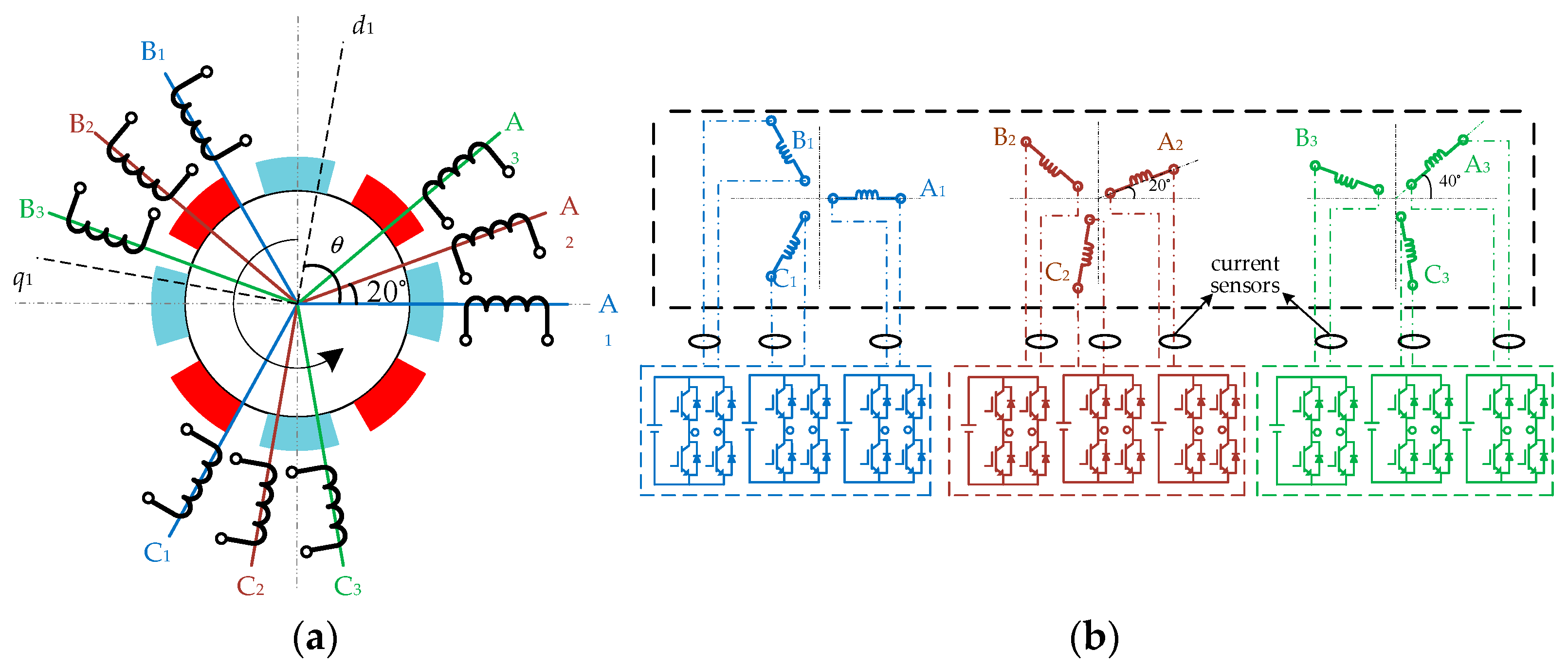
The nine-phase PMSM in this article is composed of three sets of three-phase open-end windings which are spatially shifted π/9 degrees. Each phase is equipped with an independent current sensor. An H-bridge inverter circuit drives nine-phase effectively with more control, reliability, and independence. Figure 1a shows the nine-phase PMSM windings structure, and Figure 1b shows the nine-phase H-bridge drive topology.
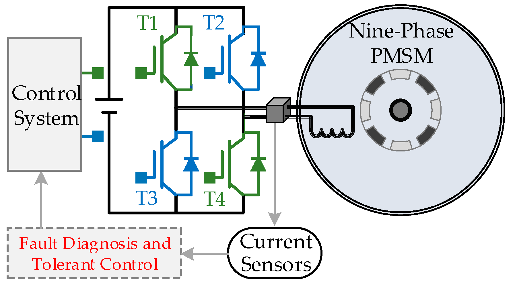
The probability of faults increases with the number of current sensors required for the nine-phase PMSM drives. The fault diagnosis and tolerant control of nine-phase PMSM drives are shown in Figure 2.
3. Influence of Current Sensor Faults on Motor Drives
Based on the frequency of faults and the degree of negative impact on the motor drives, the typical current sensor faults distinguished by output characteristics can be classified as gain fault and loss signal fault. Taking phase-A1 current sensor faults as an example, the measured phase currents of each sensor can be expressed as:
where, i*A1, i*A2 … i*C3 are the real phase currents, iA1, iA2 … iC3 are the measured values by nine-phase current sensors, λ is the gain coefficient of fault current sensor, Iam is the phase current amplitude, θori is the initial phase angle and ω is the electrical angular frequency respectively.
In normal conditions, λ = 1; when loss signal faults occur, λ = 0; when gain faults occur, λ > 1. The expression of id1 and iq1 in the d-q coordinate is in Equation (2).
Assuming that the fault of the phase-A1 current sensor in the multi-phase motor drives has little effect on the normal phase current amplitude, Equation (1) is substituted into Equation (2), then the measured value of iq1_m can be expressed.
- In normal conditions, λ = 1, DC component is zero, so iq1 is equal to iq1_m with no bias.
- When loss signal faults occur, the real phase currents are not measured by current sensors. The AC component are zero-mean pulsations; DC component is a bias less than zero due to λ = 0.
- When gain faults occur, the AC component is still zero-mean pulsations, but the DC component is a bias greater than zero due to λ > 1.
Therefore, the iq1_m impacted by the DC component can be used as the characteristic quantity to distinguish normal conditions, loss signal faults and gain faults. In addition to the fault type, the location of the fault point is also essential, so it is necessary to further propose a perfect diagnosis strategy combined with iq1_m.
4. Diagnosis for Current Sensors Faults
4.1. Improved Axis Rotation
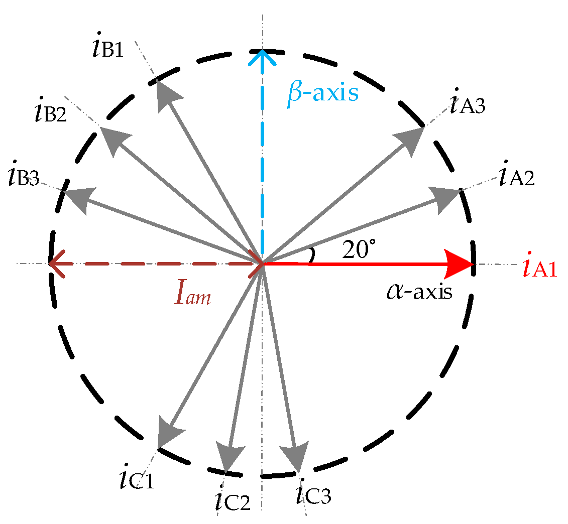
From the transformation matrix of the semi-symmetric nine-phase PMSM natural coordinate system to the synchronous stationary coordinate system (Clark), it can be seen that in the standard transformation shown in Figure 3, A1-axis and α1-axis are in the same direction. The component of phase current iA1 on β1-axis is zero and the component on α1-axis is 100% iA1.
Therefore, from the iα1 and iβ1 in Equation (4), only the current sensor fault of phase-A1 has the least influence on iβ1 and the largest influence on iα1 among all nine phases.
where, iα1_1 and iβ1_1 are fundamental wave currents of α and β when phase-A1 is used as reference axis.
In general, regarding the other phases, when different phase-N is selected as the reference axis, the Clark matrix will shift different angles θN, and current sensor faults of reference phase-N has the least influence on the corresponding iβ1_N, and the largest influence on iα1_N. The general formula of iα1_N and iβ1_N can be obtained in Equation (5).
where, the θN of stator windings of semi-symmetric nine-phase motor system can be expressed as:
When different phases are selected as reference axes, the expressions of iα1_N and iβ1_N can be obtained in Equation (7).
Therefore, the above formula shows that the iα1_1 changes the most in all iα1_N when loss signal fault (iA1 = 0) occurs in phase-A1, which is equivalent to the iα1_1 losing 100% of iA1 and iα1_1 has the lowest mean value in all iα1_N. Also, iβ1_1 has the smallest change in all iβ1_N, and the other eight iβ1_N have lost sinπ/9, sin2π/9 … sin14π/9 times of iA1, respectively.
- In normal conditions, nine iα1_N have the same mean value, and so do nine iβ1_N.
- When loss signal fault (iA1 = 0) occurs in phase-A1, the above formula shows that the iα1_1 changes the most in all iα1_N, which is the equivalent to the iα1_1 losing 100% of iA1, and iα1_1 has the lowest mean value in all iα1_N. Also, iβ1_1 has the smallest change in all iβ1_N, and the other eight iβ1_N have lost sinπ/9, sin2π/9...sin14π/9 times of iα1_1, respectively.
- When gain fault (iA1 =λi*A1) occurs in phase-A1, iα1_1 has the largest change in all iα1_N, equivalent to iα1_1 increased by 100% “(λ − 1)iA1”, which has the largest mean of all iα1_N. Additionally, iβ1_1 has the smallest change in all iβ1_N. The other phases have gained sinπ/9, sin2π/9 … sin14π/9 times of (λ − 1)iA1, respectively. iβ1_1 has the smallest mean in all iβ1_N.
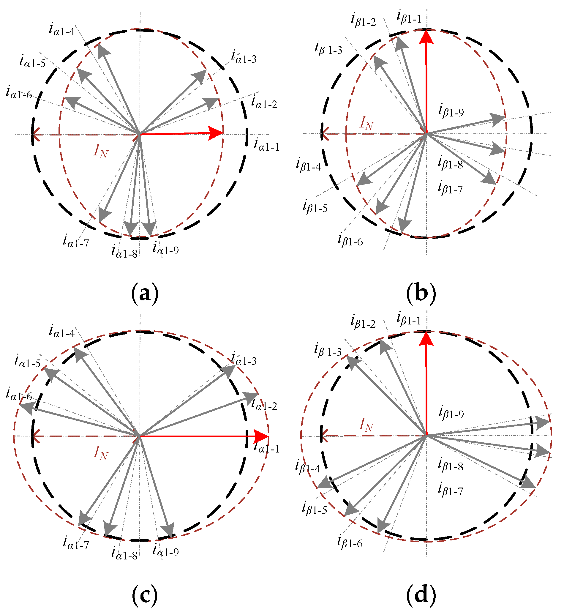
Therefore, if the mean value difference of each iα1_N and iβ1_N is selected for comparison, the difference corresponding to the fault phase is the largest, which can be used as the characteristic quantity for locating the fault phase. Taking phase-A1 faults as an example, in combination with Equation (7), the reference vectors of iα1_N and iβ1_N in each axis rotation coordinate system are shown in Figure 4.
The proposed method is based on the principle of axis rotation; iα1_N and iβ1_N always change in reverse direction after a fault, so the diagnosis variables can be designed by combining them.
4.2. Diagnosis Strategy
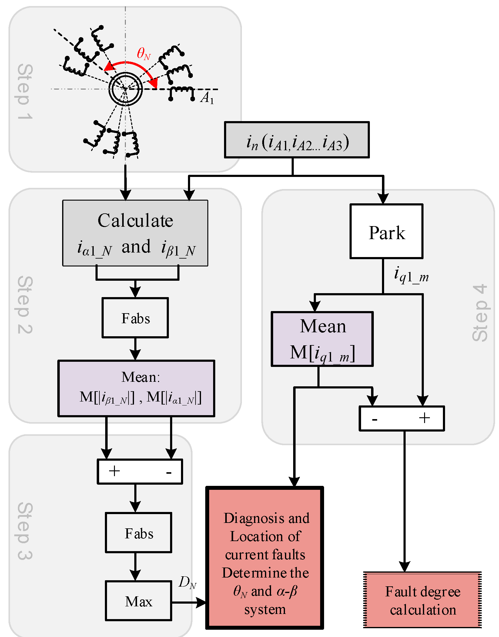
Based on the above derivation, this paper proposes a fault diagnosis method of current sensor based on improved axis rotation. The fault diagnosis of a multi-phase motor can be realized by analyzing the sampled current information of the system. Its diagnosis principle is shown in Figure 5.
Step 1: The rotation angle θN of different phases in the multi-phase motor should be determined, and the expressions of iα1_N and iβ1_N with different reference phases as α1-axis should be established according to θN. Nine-phase motors correspond to 2 × 9 expressions.
Step 2: iα1_N and iβ1_N are respectively defined as iα1_N = Iam1cos(ωt − θN), iβ1_N = Iam2sin(ωt − θN), where Iam1 and Iam2 are the current amplitude. M[|iα1_N|] and M[|iβ1_N|] are respectively obtained by the absolute-mean processor in Equation (8).
When current sensor fault occurs, the absolute-mean difference between iα1_N and iβ1_N is the largest in the axis rotation coordinate system corresponding to the fault phase. Therefore, the difference of M[|iα1_N|] and M[|iβ1_N|] can distinguish between fault and health phases.
Step 3: The fault phase of the current sensor can be located by diagnosis variables “DN = Max(|M[|iβ1_N|]-M[|iα1_N|])” after screened by the maximum calculator. The proposed method eliminates the selection of threshold value, and the phase with the strictest maximum in the all DN corresponding to the nine-phase currents is the fault phase, which greatly reduces the probability of misdiagnosis.
Step 4: The above algorithm realizes the location of the fault current sensor. However, to distinguish between gain faults and loss signal faults, the q1-axis current iq1_m is used. After processed by a mean processor and combined with Equation (3), the expression of M[iq1_m] can be obtained:
- In normal conditions, λ = 1, DC = 0, M[iq1_m] = iq1_m. There was no change in iq1_m.
- When loss signal fault occurs, λ = 0, M[AC] is a zero-mean value. So, M[iq1_m] = iq1-Iamsin(θori)/9.
- When gain faults occurs, λ > 1, M[AC] is still a zero-mean value, but M[iq1_m] = iq1 + (λ − 1)Iamsin(θori)/9.
Therefore, M[iq1_m] will be biased with different properties when the current sensor fault occurs, and the bias caused by loss signal faults and gain faults must be opposite. Therefore, the next key is to determine the DC component “Iamsin(θori)/9”.
Since iq1_m can be considered to be derived from the nine-phase current through Park transformation in Equation (5), M[iq1_m] is equivalent to the mean action of the nine-phase currents, that is, M[iq1_m] = M[cosθe × iA1] + … + M[cos(θe − 14π/9) × iC3]. Therefore, M[iq1_m] will become “8/9” of its original value after a phase current sensor fault. The expression of M[iq1_m] after faults can be obtained:
- In normal conditions, iq1_m has no DC component, iq1_m = iq1.
- When loss signal fault occurs, the DC component causes iq1_m to be 1/9 less than the iq1_m in normal conditions, that is, Iamsin(θori)/9 = iq1/9.
- When gain fault occurs, the DC component causes iq1_m more (λ − 1)Iamsin(θori)/9 than iq1_m in normal operation.
Therefore, the loss signal faults and gain faults can be distinguished by comparing the bias direction of M[iq1_m] after the faults occur.
Different from the loss signal faults, if the gain coefficient λ can be obtained when the gain fault occurs, the fault tolerant operation can be realized only by adjusting the factor of current sampling. From Equation (11), it can be concluded that the gain fault causes the fault iq1_m to be (λ − 1)iq1/9 larger than normal iq1_m. So λ can be obtained by Equation (12).
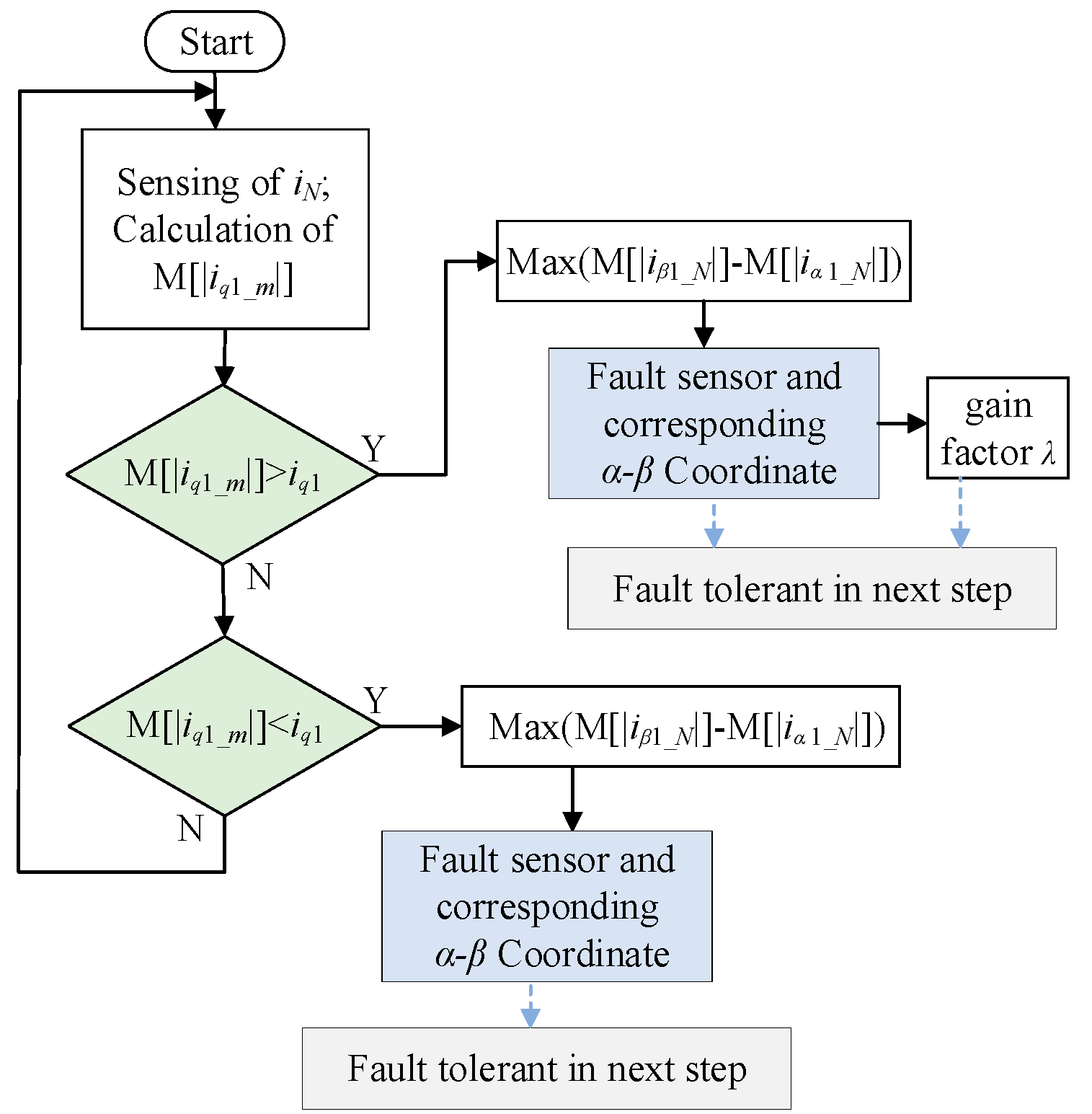
Combining with the diagnosis variables DN and M[iq1_m], the current sensor gain and loss signal faults can be distinguished and located, the gain coefficient λ of fault degree is obtained, which is prepared for fault tolerant in the next stage. The diagnosis method proposed in this paper is shown in Figure 6.
5. Tolerant Control of Current Sensors Faults
According to Section 2, iq1_m will produce different forms of pulsation and bias when the current sensor faults occur, thus affecting the stable operation of the control system. Therefore, the key to fault tolerant of current sensor depends on the correct estimation of feedback current i*d1 and i*q1. id1 and iq1 are derived from iβ1_N and iα1_N, so as long as the correct i*β1_N and i*α1_N is estimated by the appropriate algorithm, the fault tolerant operation of current sensors can be realized.
The fault diagnosis in Section 3 can locate the corresponding phase of the fault current sensor, and then determine the corresponding θA1 of axis rotation system. Taking phase-A1 as a fault example, in its corresponding rotation system, the phase current iβ1_1 remains unchanged before and after the fault, so iβ1_1 can be used as the β1-axis fault tolerant current i*β1 after the fault. The calculation of α1-axis fault tolerant current i*α1 is discussed as follows. According to Equation (10), the M[iq1_m] after loss signal fault and its value in normal conditions meet Equation (13):
So α1-axis fault tolerant current i*α1 can be obtained by the anti-Park matrix in Equation (13).
Among them, the rotation angle θA1 of the transformation matrix in Equation (14) should be selected in accordance with the θA1 determined by the fault diagnosis module.
After i*α1 and i*β1 are determined, the feedback current i*d1 and i*q1 can be obtained from the rotation matrix corresponding to θA1.
i*d1 and i*q1 are incorporated into the control system as fault tolerant feedback to realize fault tolerant operation of current sensor fault. Thus, i*α1, i*β1, i*d1 and i*q1 are obtained by rotation transformation with the same angle θA1. The θA1 corresponding to the fault can be determined only by the fault detection module, that is, fault diagnosis and fault tolerant operate in the same rotation transformation system, realizing the integration of diagnosis and fault tolerant. It is worth noting that the combination of fault diagnosis and fault-tolerant control module needs to consider the correspondence of θN. As a bridge connecting diagnosis and tolerance, the selection of θN determines the accuracy of fault tolerance current i*q1. Moreover, for gain faults, fault-tolerant control can be realized directly and accurately only by compensating a calculated gain coefficient λ (Equation (12)) for the fault phase current.
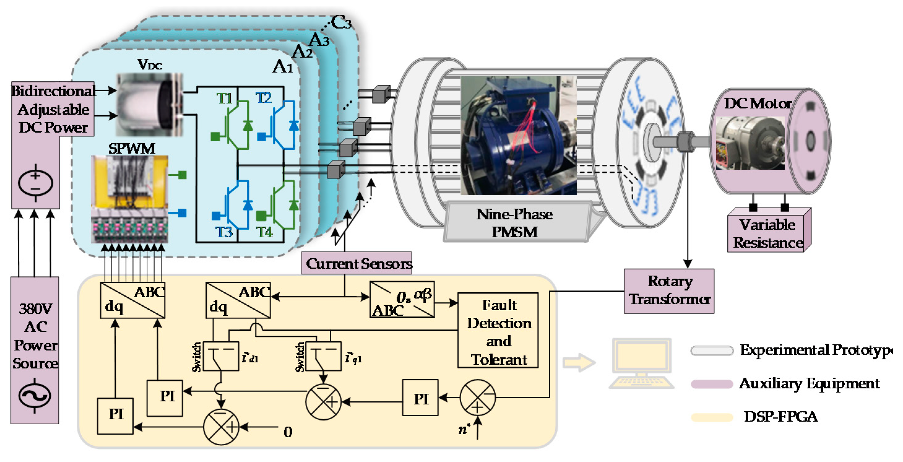
The proposed method used stator currents to diagnosis current sensor faults and obtained tolerant control by estimating and switching the iq1. Therefore, is strongly adaptable to a different controller. Additionally, the discussion and verification of the proposed method in this paper are operated under a vector control system (Figure 7).
6. Experimental Verification
6.1. Experimental Setup
In order to verify the validity of the fault diagnosis and fault tolerant method proposed in this paper, an experimental platform of nine-phase PMSM was built. The platform consists of a DC power, a controller, a 9 kw nine-phase PMSM, a DC motor, a speed-torque measuring instrument, and a voltage source inverter (VSI). The 9 kw nine-phase PMSM is powered by VSI; H-bridge inverter circuits drive each phase respectively, and the load shaft is connected with a DC generator. The block diagram of the motor control principle is shown Figure 7. The parameters of nine-phase PMSM are shown in Table 1.
6.2. Loss Signal Fault Diagnosis
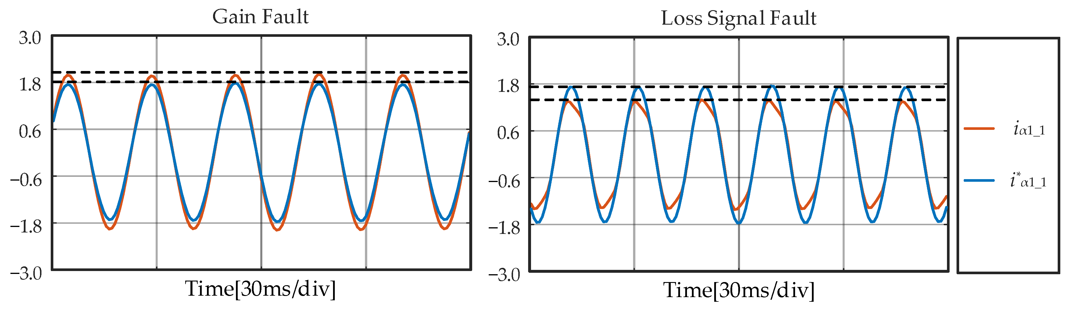
Some literature on axis rotation uses the difference between iα1_1 and i*α1_1 as diagnosis variables [24]. Thresholds are introduced to distinguish normal conditions from current sensor faults. Because this threshold is so similar in gain and loss signal faults (Figure 8), the algorithm presented in [24] cannot distinguish them effectively.
In this paper, the mean value difference of each iα1_N and iβ1_N is selected for comparison, the “DN = Max(|M[|iβ1_N|] − M[|iα1_N|])” corresponding to the fault phase is the largest, which can be used to locate the fault without the selection of a threshold.
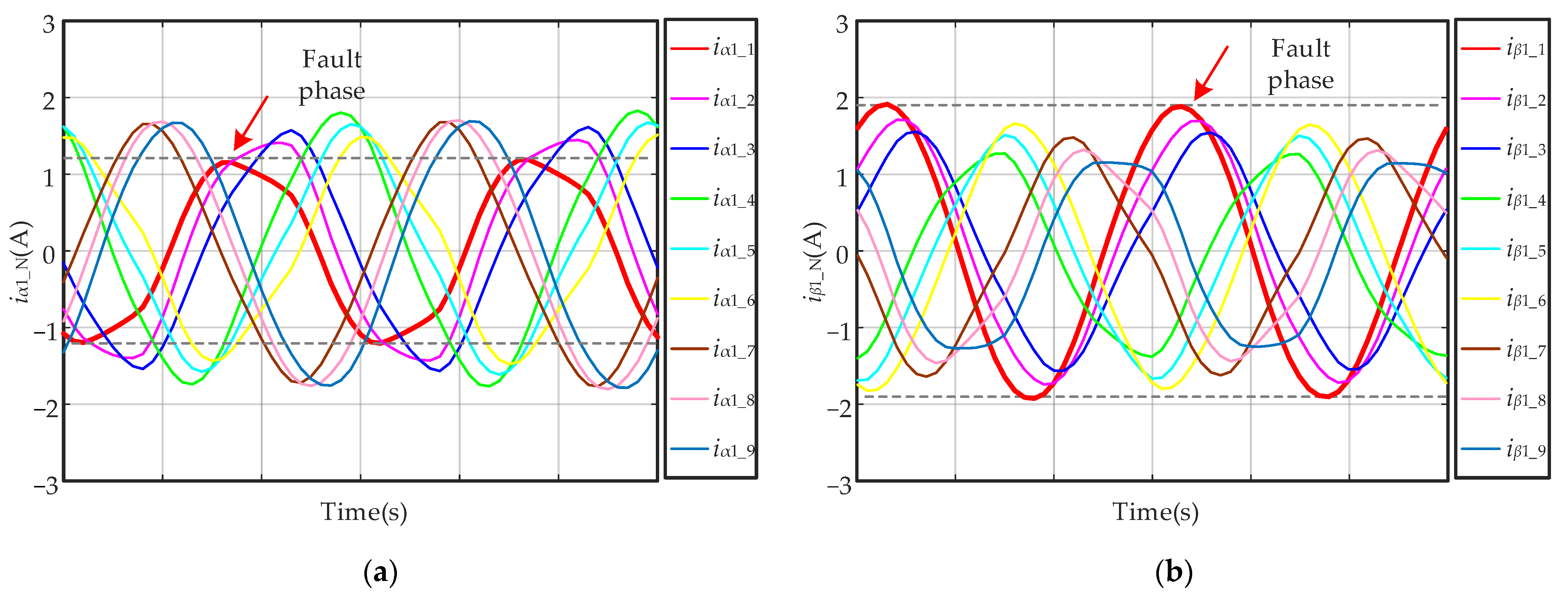
First, the motor operates stably with 25 Nm load. Then, the output of the phase-A1 current sensor is set to zero through simulation in DSP. The corresponding i*α1_N and i*β1_N are shown in Figure 9.
When iA1 = 0, the loss signal fault occurs in phase-A1. According to the Equation (7), among the nine iα1_N and iβ1_N obtained by the axis rotation system, iα1_1 is most affected and iβ1_1 keeps the amplitude almost constant. Thus, it can be seen in the Figure 8 that iα1_1 becomes the current with the lowest amplitude, and conversely, iβ1_1 becomes the one with the highest amplitude.
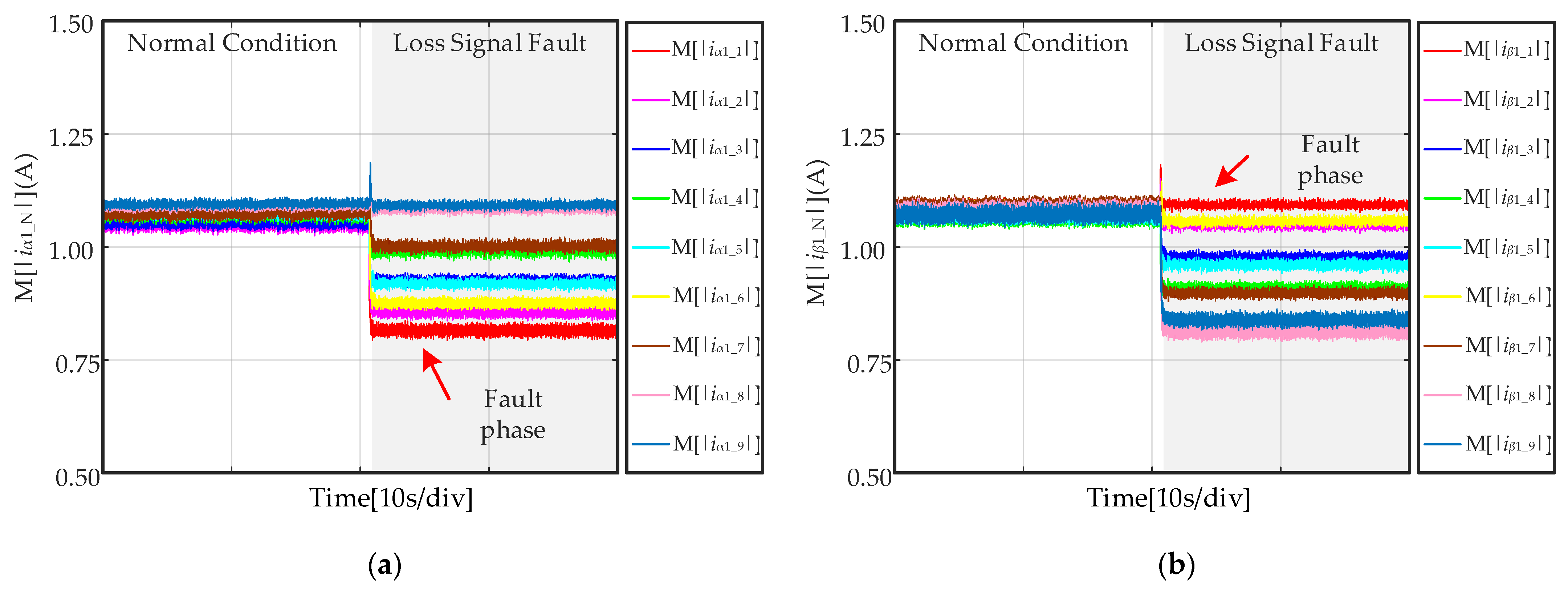
Figure 10 shows the M[|iα1_N|] and M[|iβ1_N|] calculated by absolute-mean processors. Due to the linear relationship between amplitude and absolute-mean in Equation (8), the value of M[|iα1_1|] is the smallest of the nine M[|iα1_N|]. Similarly, M[|iβ1_1|] is the largest one of the nine M[|iβ1_N|].
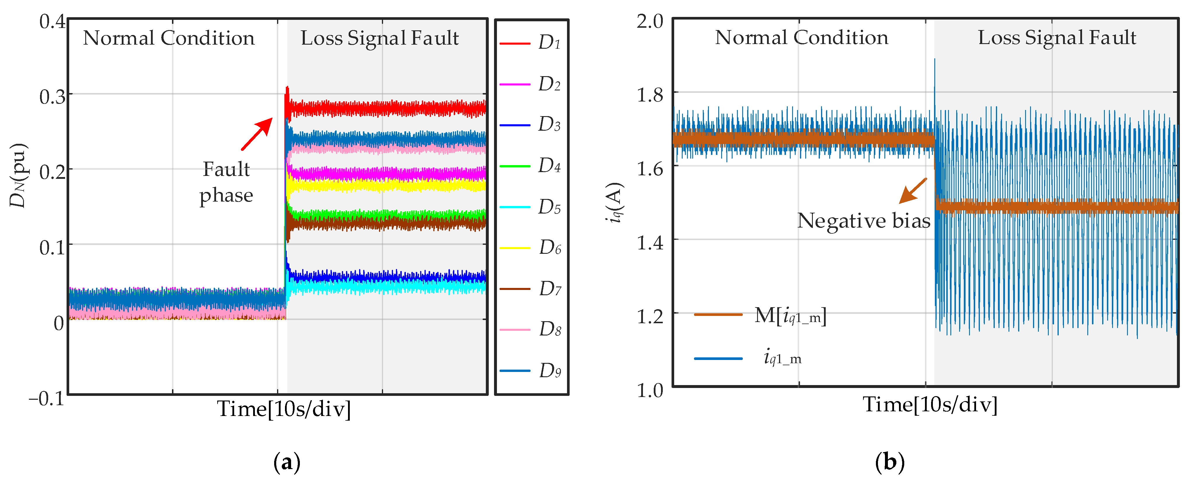
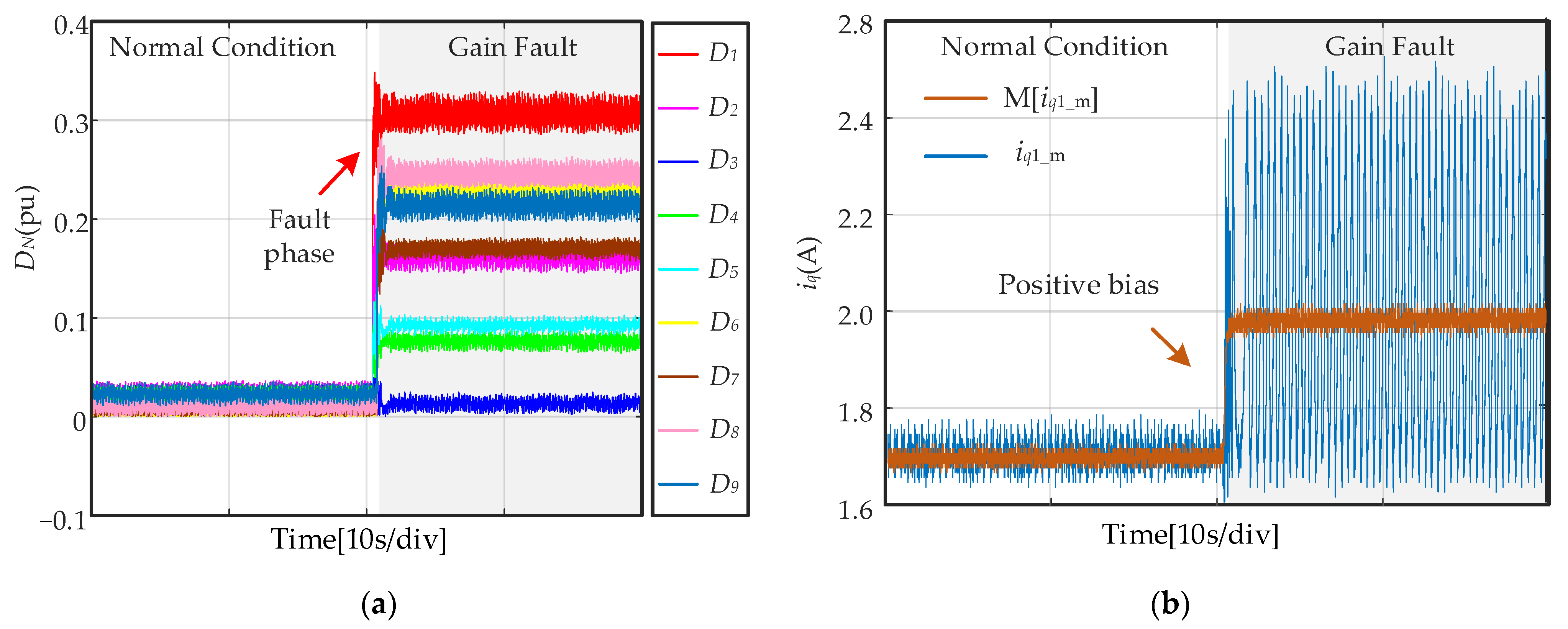
Figure 11 shows the diagnosis variables DN and M[iq1_m]. In normal conditions, each DN are almost equal and approximately zero. When a current sensor fault occurs, the difference between M[|iα1_N|] and M[|iβ1_N|] of the fault phase is strictly maximum in Figure 10. Therefore, D1 is the max value of nine DN, so the fault phase can be located. Moreover, iq1_m has a negative DC bias “−Iamsin(θori)/9”, a zero-mean pulse. Thus, M[iq1_m] in a loss signal fault is less than it is in normal conditions, so the loss signal fault of phase-A1 current sensor can be diagnosed.
6.3. Gain Fault Diagnosis
This fault diagnosis experiment is to verify the validity of the proposed method for current sensor gain fault. When a 2.5 times gain fault of phase-A1 current sensor is set through simulation in DSP. The corresponding i*α1_N and i*β1_N are shown in Figure 12.
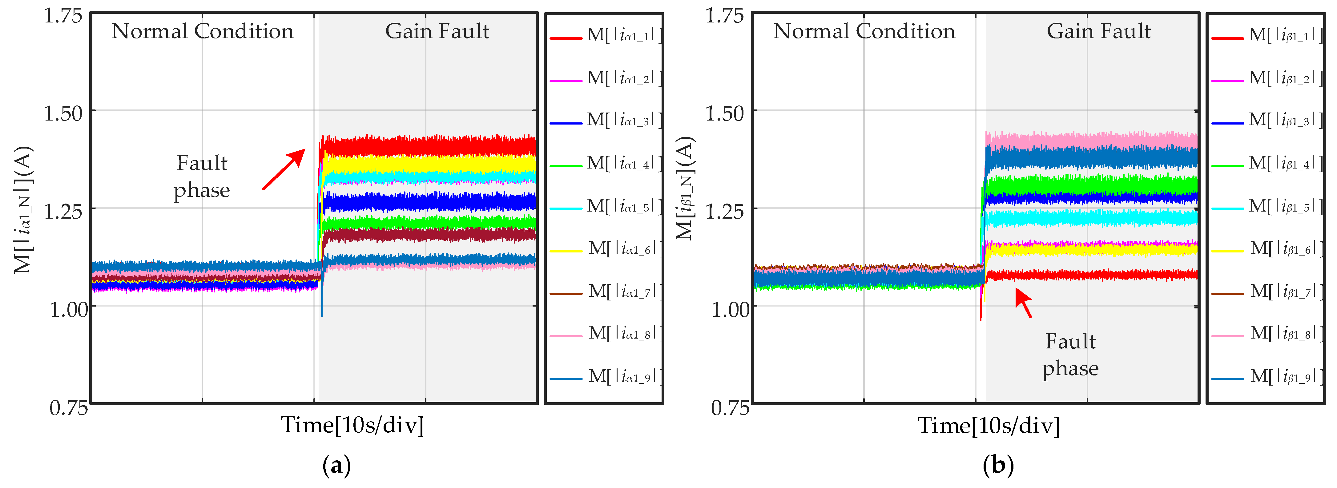
When the loss signal fault occurs in phase-A1 (iA1 = 2.5i*A1), iα1_1 is most affected while iβ1_1 keeps the constant amplitude. According to Equation (7), iα1_1 becomes the current with the largest amplitude and iβ1_1 becomes the one with the smallest amplitude. The M[|iα1_N|] and M[|iβ1_N|] calculated by absolute-mean processors are shown in Figure 12. Therefore, the value of M[|iα1_1|] is the largest of the nine M[|iα1_N|], and M[|iβ1_1|] is the smallest one of the nine M[|iβ1_N|].
Figure 13 shows the diagnosis variables DN and M[iq1_m]. Each DN are approximately zero in normal conditions. When the fault occurs, the difference between M[|iα1_N|] and M[|iβ1_N|] of the fault phase is strictly maximum in Figure 13. Therefore, D1 is also the max value of DN, so the fault phase-A1 can be located. Moreover, iq1_m has a distinct positive DC bias “1.5Iamsin(θori)/9” and a zero-mean pulse. Thus, M[iq1_m] in loss signal fault is greater than it is in normal conditions, which can be used to further diagnose tolerant control. So, the loss signal fault of phase-A1 current sensor can be diagnosed.
The threshold selection is eliminated in the whole diagnosis process, and the loss signal faults can be located by selecting the phase with the maximum value of the diagnosis variables DN. M[iq1_m] has an obvious negative bias feature, which makes the distinction between loss signal and gain faults more accurate.
6.4. Loss Signal Fault Tolerant
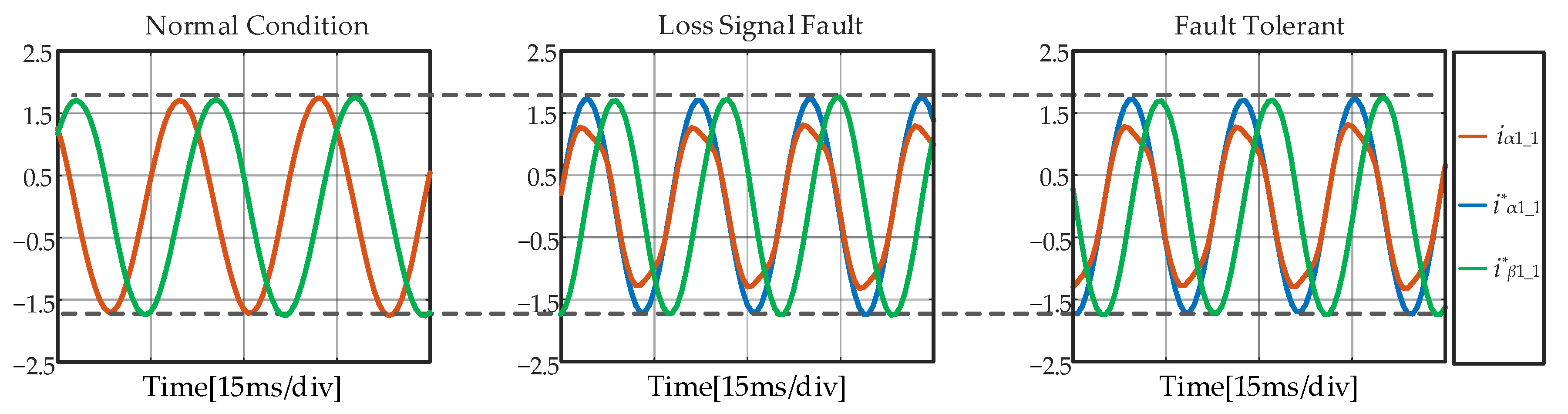
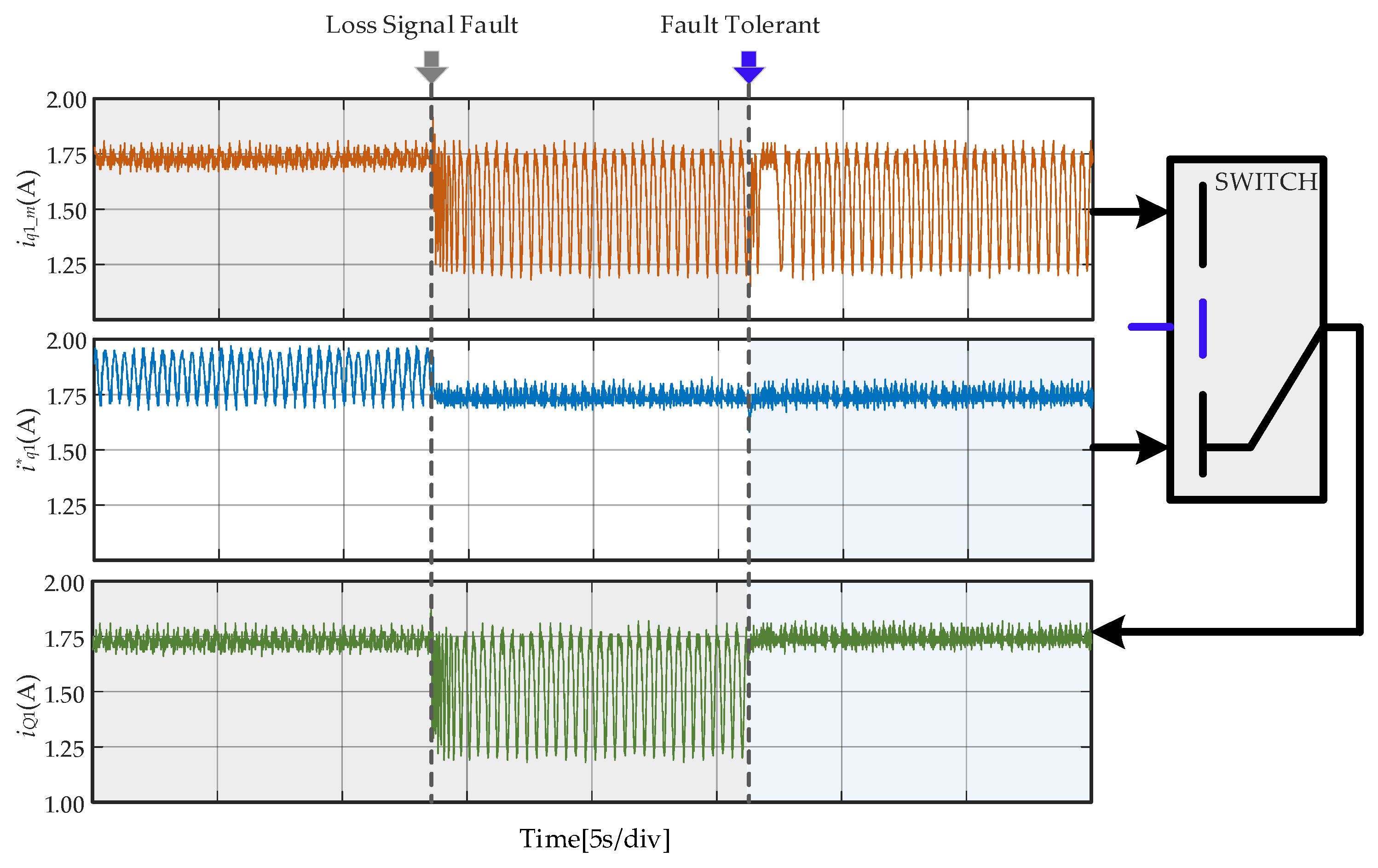
In order to verify the effectiveness of the proposed fault tolerant method, the loss signal fault-tolerant control experiment is shown as follows: iα1_1 and iβ1_1 are the actual currents, i*α1_1 and i*β1_1 are the fault tolerant currents. Since iβ1_1 remains almost constant when fault occurs, iβ1_1 can be directly referred to as i*β1_1. And the conversion between iq1_m and fault tolerant current i*q1 is realized by the switch designed in DSP.
In Figure 14, iα1_1 and iβ1_1 (i*β1_1) have similar amplitude in normal conditions. However, due to the existence of a correction factor of 9/8 in Equation (12), the amplitude of the fault tolerant current i*α1_1 is slightly higher than iα1_1 and i*β1_1. When the loss signal fault occurs in A1, iα1_1 is most affected and i*β1_1 keeps almost constant but the tolerant current i*α1_1 has the same amplitude as iα1_1 in normal condition. Before and after the fault-tolerant control, i*α1_1 can maintain a stable correct amplitude, so that it can be connected to the system together with i*β1_1 as the fault tolerant current.
Figure 15 shows that iq1_m produces a large pulse due to the DC bias and AC pulsation when faults occur. At this time, the current iQ1 connected to the feedback system is still iq1_m. Then, the switch is given a fault tolerant signal and it selects i*q1 to be transferred to the output. Therefore, the feedback current iQ1 is restored to iq1_m in normal condition, and fault-tolerant control is realized.
6.5. Gain Fault Tolerant
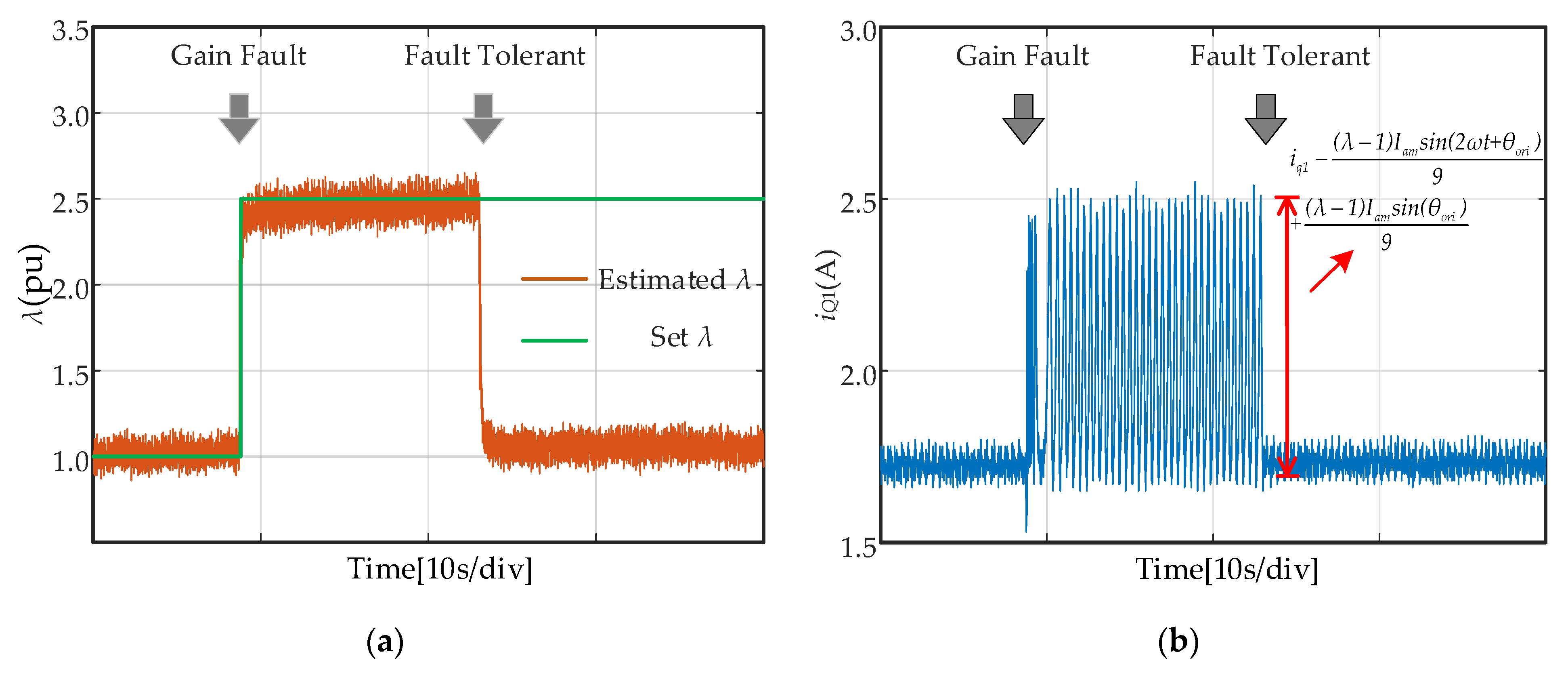
The proposed method can estimate the gain coefficient λ, which can be used as the correction factor of the fault phase current sensor, and can achieve fault-tolerant control directly and accurately.
In Figure 16a, when a 2.5 times gain fault of a phase-A1 current sensor is set, the estimated coefficient λ has good tracking effect in normal and fault conditions. Therefore, fault-tolerant control can be realized by compensating the gain coefficient of the fault current sensor in DSP. After compensation, the estimated λ and iq1_m are both restored to normal values.
Different from the existing algorithms, the proposed method can estimate the gain coefficient λ, which can be used as the correction factor of the fault sensor. The fault-tolerant control achieves tolerant accuracy by applying this factor.
7. Conclusions
In this paper, a fault diagnosis and tolerant control method is proposed to different kinds of current sensor faults in multi-phase PMSM drives. It is desirable that the method utilizes the stator currents signal-processing, making it even simpler and less computationally demanding. It is also worth noting that the diagnosis variables have distinct characteristics which eliminate (to some extent) the margin of the design of the threshold. This method can distinguish between loss signal and gain faults effectively and lacks operating condition dependence. Moreover, the degree of current sensor gain fault can be quantitatively described by an estimated coefficient. Finally, fault diagnosis and tolerant control experiments are presented, which show the effectiveness and rapidity regarding the method. The optimization of diagnosis variables when multiple faults occur is the next focus.
Author Contributions
Conceptualization, X.Z. (Xudong Zhang); Funding acquisition, X.Z. (Xiaoqin Zheng); Methodology, X.Z. (Xudong Zhang); Software, X.L.; Visualization, X.L.; Writing—original draft, X.Z. (Xudong Zhang); Writing—review & editing, X.Z. (Xiaoqin Zheng). All authors have read and agreed to the published version of the manuscript.
Funding
This research was funded by the National Natural Science Foundation of China, grant number 51907093, 52037005, U2106217.
Institutional Review Board Statement
Not applicable.
Informed Consent Statement
Not applicable.
Data Availability Statement
Not applicable.
Acknowledgments
Thanks to Xinzhen Wu and Haifeng Wang for experimental guidance and writing suggestions for this article.
Conflicts of Interest
The authors declare no conflict of interest.
References
- Liu, Z.; Fang, L.; Jiang, D.; Qu, R. A Machine-Learning-Based Fault Diagnosis Method with Adaptive Secondary Sampling for Multiphase Drive Systems. IEEE Trans. Power Electron. 2022, 37, 8767–8772. [Google Scholar] [CrossRef]
- Chen, C.; Xu, J.; Yuan, X.; Wu, X. Characteristic Analysis of the Peak Braking Force and the Critical Speed of Eddy Current Braking in a High-Speed Maglev. Energies 2019, 12, 2622. [Google Scholar] [CrossRef] [Green Version]
- Wang, H.; Zheng, X.; Yuan, X.; Wu, X. Low-Complexity Model-Predictive Control for a Nine-Phase Open-End Winding PMSM with Dead-Time Compensation. IEEE Trans. Power Electron. 2022, 37, 8895–8908. [Google Scholar] [CrossRef]
- Wang, J.; Jiang, W.; Wang, S.; Lu, J.; Williams, B.W.; Wang, Q. A Novel Step Current Excitation Control Method to Reduce the Torque Ripple of Outer-Rotor Switched Reluctance Motors. Energies 2022, 15, 2852. [Google Scholar] [CrossRef]
- Wang, H.; Wu, X.; Zheng, X.; Yuan, X. Virtual Voltage Vector Based Model Predictive Control for a Nine-Phase Open-End Winding PMSM With a Common DC Bus. IEEE Trans. Ind. Electron. 2022, 69, 5386–5397. [Google Scholar] [CrossRef]
- Harikumaran, J.; Buticchi, G.; Galea, M.; Wheeler, P. Open Phase Fault Tolerant Control of Multi Three Phase Machines. IEEE Trans. Power Electron. 2021, 2, 535–544. [Google Scholar] [CrossRef]
- Zhao, B.; Gong, J.; Tong, T.; Xu, Y.; Semail, E.; Nguyen, N.K.; Gillon, F. A Novel Five-Phase Fractional Slot Concentrated Winding with Low Space Harmonic Contents. IEEE Trans. Magn. 2021, 57, 1–5. [Google Scholar] [CrossRef]
- Nguyen, N.K.; Meinguet, F.; Semail, E.; Kestelyn, X. Fault-Tolerant Operation of an Open-End Winding Five-Phase PMSM Drive With Short-Circuit Inverter Fault. IEEE Trans. Ind. Electron. 2016, 63, 595–605. [Google Scholar] [CrossRef] [Green Version]
- Foo, G.H.B.; Zhang, X.; Vilathgamuwa, D.M. A Sensor Fault Detection and Isolation Method in Interior Permanent-Magnet Synchronous Motor Drives Based on an Extended Kalman Filter. IEEE Trans. Ind. Electron. 2013, 60, 3485–3495. [Google Scholar] [CrossRef]
- Xiahou, K.S.; Lin, X.; Wu, Q.H. Current sensor fault-tolerant control of DFIGs using stator current regulators and Kalman filters. In Proceedings of the 2017 IEEE Power & Energy Society General Meeting (PESGM), Chicago, IL, USA, 16–20 July 2017; pp. 1–5. [Google Scholar]
- Wang, G.; Hao, X.; Zhao, N.; Zhang, G.; Xu, D. Current Sensor Fault-Tolerant Control Strategy for Encoderless PMSM Drives Based on Single Sliding Mode Observer. IEEE Trans. Transp. Electrific. 2020, 6, 679–689. [Google Scholar] [CrossRef]
- Yu, Y.; Zhao, Y.; Wang, B.; Huang, X.; Xu, D. Current Sensor Fault Diagnosis and Tolerant Control for VSI-Based Induction Motor Drives. IEEE Trans. Power Electron. 2018, 33, 4238–4248. [Google Scholar] [CrossRef]
- Jlassi, I.; Estima, J.; El Khil, O.S.K.; Bellaaj, N.M.; Cardoso, A.J.M. A Robust Observer-Based Method for IGBTs and Current Sensors Fault Diagnosis in Voltage-Source Inverters of PMSM Drives. IEEE Trans. Ind. Appl. 2017, 53, 2894–2905. [Google Scholar] [CrossRef]
- Zhang, G.; Zhou, H.; Wang, G.; Li, C.; Xu, D. Current Sensor Fault-Tolerant Control for Encoderless IPMSM Drives Based on Current Space Vector Error Reconstruction. IEEE J. Emerg. Sel. Topics Power Electron. 2020, 8, 3658–3668. [Google Scholar] [CrossRef]
- Li, Z.; Wheeler, P.; Watson, A.; Costabeber, A.; Wang, B.; Ren, Y.; Bai, Z.; Ma, H. A Fast Diagnosis Method for Both IGBT Faults and Current Sensor Faults in Grid-Tied Three-Phase Inverters with Two Current Sensors. IEEE Trans. Power Electron. 2020, 35, 5267–5278. [Google Scholar] [CrossRef]
- Venghi, L.E.; Aguilera, F.; de la Barrera, P.M.; De Angelo, C.H. Single-Observer Based Current Sensor Fault Tolerant Control for IM Traction Drives. IEEE Lat. Am. Trans. 2021, 19, 2087–2096. [Google Scholar] [CrossRef]
- Sakthivel, R.; Kavikumar, R.; Mohammadzadeh, A.; Kwon, O.-M.; Kaviarasan, B. Fault Estimation for Mode-Dependent IT2 Fuzzy Systems With Quantized Output Signals. IEEE Trans. Fuzz Syst. 2021, 29, 298–309. [Google Scholar] [CrossRef]
- Venghi, L.E.; Aguilera, F.; de la Barrera, P.M.; De Angelo, C.H. Detection and isolation of current-sensor and open-switch faults in electric traction drives. IEEE Latin Am. Trans. 2021, 19, 1335–1346. [Google Scholar] [CrossRef]
- Ruba, M.; Nemeş, R.O.; Ciornei, S.M.; Marţiş, C. Simple and Robust Current Sensor Fault Detection and Compensation Method for 3-Phase Inverters. IEEE Access 2020, 8, 34820–34832. [Google Scholar] [CrossRef]
- Wu, C.; Guo, C.; Xie, Z.; Ni, F.; Liu, H. A Signal-Based Fault Detection and Tolerance Control Method of Current Sensor for PMSM Drive. IEEE Trans. Ind. Electron. 2018, 65, 9646–9657. [Google Scholar] [CrossRef]
- Huang, W.; Du, J.; Hua, W.; Lu, W.; Bi, K.; Zhu, Y.; Fan, Q. Current-Based Open-Circuit Fault Diagnosis for PMSM Drives With Model Predictive Control. IEEE Trans. Power Electron. 2021, 36, 10695–10704. [Google Scholar] [CrossRef]
- Wang, W.; Tian, W.; Wang, Z.; Hua, W.; Cheng, M. A Fault Diagnosis Method for Current Sensors of Primary Permanent-Magnet Linear Motor Drives. IEEE Trans. Power Electron. 2020, 36, 2334–2345. [Google Scholar] [CrossRef]
- Tran, C.D.; Palacky, P.; Kuchar, M.; Brandstetter, P.; Dinh, B.H. Current and Speed Sensor Fault Diagnosis Method Applied to Induction Motor Drive. IEEE Access 2021, 9, 38660–38672. [Google Scholar] [CrossRef]
- Chakraborty, C.; Verma, V. Speed and Current Sensor Fault Detection and Isolation Technique for Induction Motor Drive Using Axes Transformation. IEEE Trans. Ind. Electron. 2015, 62, 1943–1954. [Google Scholar] [CrossRef]
Figure 1.
(a) Winding structure of nine-phase PMSM; (b) H-bridge drive topology.

Figure 2.
Diagram of diagnosis and tolerant control of nine-phase PMSM drives.

Figure 3.
The standard Clark transformation.

Figure 4.
(a) iα1_N in loss signal fault; (b) iβ1_N in loss signal fault; (c) iα1_N in gain fault; (d) iβ1_N in gain fault.
Figure 4.
(a) iα1_N in loss signal fault; (b) iβ1_N in loss signal fault; (c) iα1_N in gain fault; (d) iβ1_N in gain fault.

Figure 5.
Block diagram of proposed method.

Figure 6.
Flowchart of proposed method.

Figure 7.
Control system of a nine-phase PMSM motor.

Figure 8.
iα1_1 and i*α1_1 in different faults.

Figure 9.
(a) iα1_N in loss signal fault; (b) iβ1_N in loss signal fault.

Figure 10.
(a) M[|iα1_N|] in loss signal fault; (b) M[|iβ1_N|] in loss signal fault.

Figure 11.
(a) DN in loss signal fault; (b) M[iq1_m] and iq1_N in loss signal fault.

Figure 12.
(a) M[|iα1_N|] in gain fault; (b) M[|iβ1_N|] in gain fault.

Figure 13.
(a) DN in gain fault; (b) M[iq1_m] and iq1_N in gain fault.

Figure 14.
iα1_1, i*α1_1 and i*β1_1 in different conditions.

Figure 15.
iq1_m, i*q1 and iQ1 in different conditions.

Figure 16.
(a) Estimated λ and set λ; (b) iQ1.


Table 1.
Nine-phase PMSM parameters.
| Parameters | Value |
|---|---|
| Power | 9 kw |
| Voltage | 234 V |
| Current | 4.6 A |
| Speed | 900 rpm |
| Torque | 95.5 Nm |
| d-axis inductance | 41.2 mH |
| q-axis inductance | 41.2 mH |
| Armature resistance | 2.47 Ω |
| Magnet flux linkage | 0.8524 Wb |
| pole-pairs | 4 |
| Rotational inertia/kg·m2 | 0.03128 |
Publisher’s Note: MDPI stays neutral with regard to jurisdictional claims in published maps and institutional affiliations. |
© 2022 by the authors. Licensee MDPI, Basel, Switzerland. This article is an open access article distributed under the terms and conditions of the Creative Commons Attribution (CC BY) license (https://creativecommons.org/licenses/by/4.0/).
Share and Cite
MDPI and ACS Style
Zhang, X.; Liu, X.; Zheng, X. Current Sensor Fault Diagnosis and Tolerant Control for Nine-Phase PMSM Drives Based on Improved Axis Rotation. Energies 2022, 15, 4671. https://doi.org/10.3390/en15134671
AMA Style
Zhang X, Liu X, Zheng X. Current Sensor Fault Diagnosis and Tolerant Control for Nine-Phase PMSM Drives Based on Improved Axis Rotation. Energies. 2022; 15(13):4671. https://doi.org/10.3390/en15134671
Chicago/Turabian StyleZhang, Xudong, Xiaoming Liu, and Xiaoqin Zheng. 2022. "Current Sensor Fault Diagnosis and Tolerant Control for Nine-Phase PMSM Drives Based on Improved Axis Rotation" Energies 15, no. 13: 4671. https://doi.org/10.3390/en15134671
Note that from the first issue of 2016, this journal uses article numbers instead of page numbers. See further details here.