
Investigation of Pressure Coefficient Distribution on the Surface of a Modular Building


1
Department of Construktion Organization and Technology, Czestochowa University of Technology, 42-201 Czestochowa, Poland
2
Department of Heat and Gas Supply and Ventilation, Lviv Polyechnic National University, 79013 Lviv, Ukraine
3
Department of HVAC Engineering, Bialystok University of Technology, 15-351 Bialystok, Poland
*
Author to whom correspondence should be addressed.
Energies 2022, 15(13), 4644; https://doi.org/10.3390/en15134644
Submission received: 13 June 2022
/
Revised: 22 June 2022
/
Accepted: 23 June 2022
/
Published: 24 June 2022
Abstract
:This article considers the distribution of the pressure coefficient on the surface of a modular house model in order to further assess the possibility of operation of a thermosyphon solar collector integrated into the external protection. The experiment was planned to estimate the factors influencing the value of the aerodynamic coefficient. The results of experimental studies conducted in a wind tunnel are presented. The obtained graphical dependences were compared with the results of computer simulations and convergence was evaluated.

1. Introduction
Modern construction technologies require significant expenditures of energy resources and materials, which in turn makes the construction industry one of the largest producers of waste and pollutants. From an economic point of view, this sector has a negative impact on the environment, emitting tons of greenhouse gases into the atmosphere, which in turn increases global warming and ozone depletion. However, the environmental performance of the construction industry may differ significantly in different geographical regions [1]. One of the important ways to solve this global problem is the use of modular construction. The strategy of construction companies and production centers for the production of modular prefabricated building structures will reduce the consumption of materials and energy, which in turn will improve the impact on the environment [2,3]. In addition, the use of renewable energy sources for innovative life support technologies for modular buildings remains an important factor in reducing the negative impact on the environment [4].
However, it should be emphasized that modularity in construction is an appropriate approach to the development of design solutions, and should provide flexibility in the operation of a building during its life cycle [5,6]. A number of scientific works are devoted to this problem, in which much attention was paid to solving the problem of modularity; various new types of connections of building structures are proposed [7,8,9,10,11], as well as innovative building materials [12].
This approach to modularity makes it possible to address the ambitious initiatives of the governments of a number of countries to provide affordable and quality housing for the economically disadvantaged and low-income groups. Even inexpensive building structures can, to some extent, meet the standards and requirements for maintaining the microclimate and ensure a long life cycle of modular buildings [13,14]. Rapid construction technologies are important, especially in emergencies. Outdoor modular design is ideal for such cases [15,16,17,18]. The original solution to this problem is the use of sea containers. Although such methods of rapid construction require solving many problems, including the organization of international standardization, determining the structural strength of the structure, including under the action of wind pressure [19,20,21,22,23], and the use of BIM technologies in design. Recently, there has been a surge in the use of construction information modeling (BIM) and this has accelerated the development of the construction industry. The integration of BIM technologies into industrialization is seen as a prospect for possible improvement of modular construction [24,25]. This approach avoids a number of design errors, as it often happens that in order to quickly build a facility, construction and design occur simultaneously [26,27,28]. Also, an important positive point in this approach is the high level of detail of the set of components of the building [29]. This improves the environmental performance of construction compared to conventional technologies, as there is the possibility of multiple uses of components and materials [30]. Environmental performance is one of the most important aspects, leading to a long life cycle of modular buildings of various types, including residential, commercial, educational and medical [31].
Another important aspect of modular construction that needs to be addressed in the current environment of organic energy shortages is energy efficiency, which is based on reducing energy consumption through the use of innovative life support systems. For example, radiant heating systems that maintain a comfortable indoor environment, the temperature of which can reach 21 °C, have a vertical temperature gradient below 3 °C [32]. Infrared heaters integrated into the building’s enclosing structures reduce the thermal inertia of the building. The use of alternative energy sources to maintain the thermal state has an unconditional impact on the energy efficiency of the building. Hybrid outdoor protection in combination with technologies for converting solar energy into heat can significantly reduce the load on traditional systems for providing microclimate parameters [33]. The microclimates in the premises of modular buildings also need special attention, as they significantly affect the physiological state of the human body and its efficiency. Hybrid external protections of the modular house have essential thermal stability and tightness on air permeability. Microclimate maintenance systems in this case have an important task to ensure the supply of fresh air and constant monitoring of the concentration of carbon dioxide in the room, which may vary depending on the presence of people [34].
After analyzing the uniqueness of design, construction and features of the requirements for efficient and safe operation of modular buildings, it was concluded that unfortunately there is no data on guidelines for architectural forms and their aerodynamic characteristics for modular buildings. Instead, data on the stability of lightweight structures under wind pressure were utilized [35,36,37,38,39], but do not consider the issue of assessing the impact of air flow on the energy performance of the building. Therefore, the author set himself the task to study the aerodynamic characteristics of the modular building, to identify features of the distribution of the pressure coefficient on its surface and to draw conclusions about the possibility of using a thermosyphon solar collector in hybrid exterior protections.
2. Materials and Methods
2.1. Determination of Aerodynamic Characteristics of the House
The purpose of the aerodynamic research was to establish features of the character of distribution of aerodynamic factors on the surface of a modular house, and to analyze the functionality of the thermosyphon solar collector implemented in external protection. Furthermore, the research allows the evaluation of the operation of the thermosyphon solar collector in oncoming undisturbed air flow at different speeds.
Setting the task for the experiment involved determination of pressure coefficients on the surface of the house and in the prayer places of ventilation holes in the thermosyphon solar collector caused by oncoming undisturbed air flow. Construction of graphical dependences of pressure coefficients depended on dimensionless linear coordinates. The research was carried out for the most unfavorable variant of operation of the thermosyphon solar collector, i.e., at the angle of the wind flow α = 0° directed to the outer facade of the modular building with the built-in thermosyphon solar collector.
Experimental installation for the study of aerodynamic characteristics of a modular building involved the manufacturing of an experimental physical model. It was decided to create a hollow model of a modular building at a scale of 1:16 with a thermosyphon solar collector integrated into the outer wall. The main component was used corrugated cardboard, which does not differ in aerodynamic characteristics from metal or concrete.
Given the actual size of the house and the layout of the working part of the wind tunnel (diameter of the working part was 1.0 m), the maximum area of the model should be within 5–15% of the cross-sectional area of the working part of the wind tunnel. In our case, depending on the angle of attack, the cross-sectional area of the model was 14.4% of the working area of the pipe.
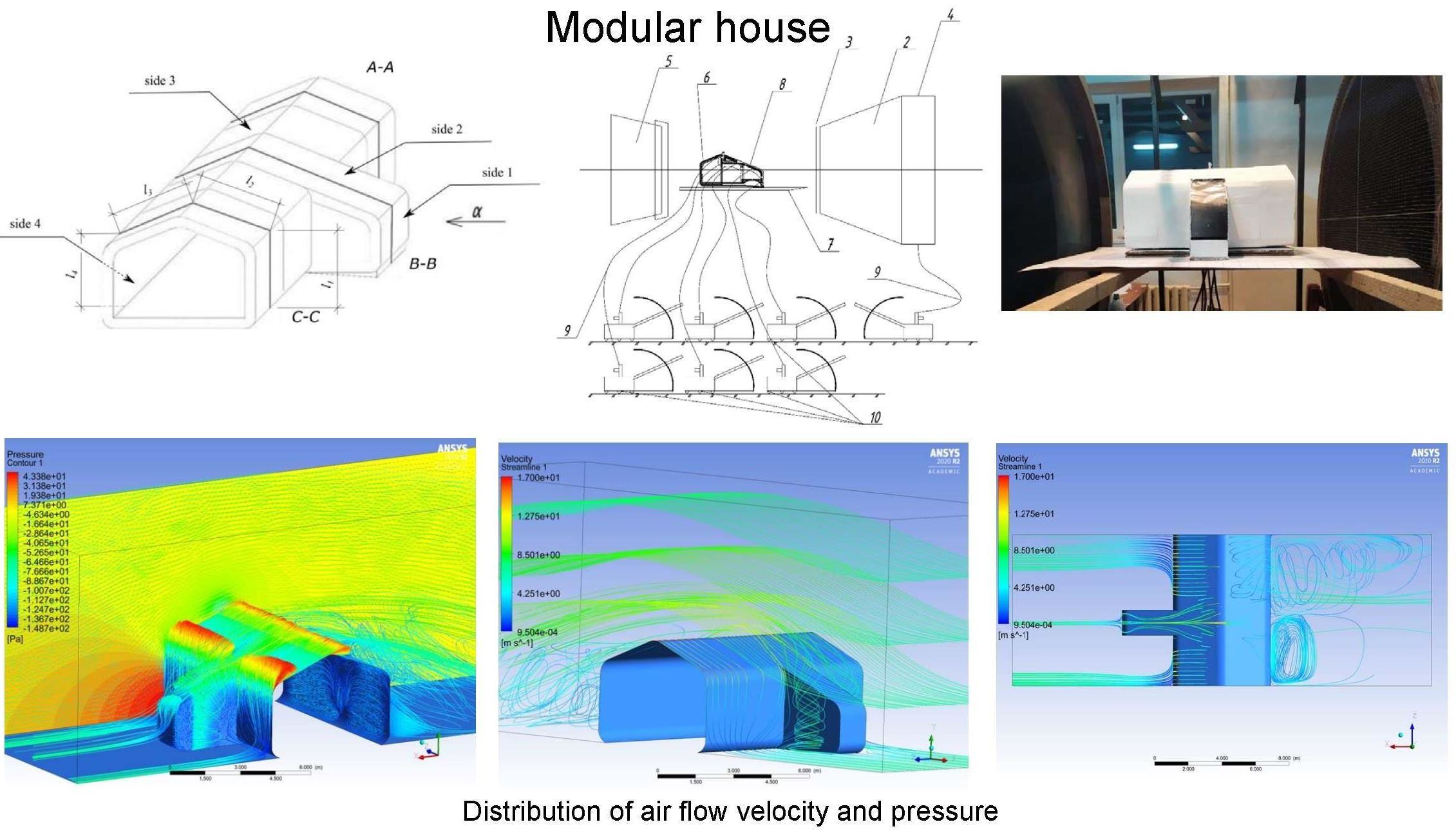
Figure 1, (a) shows a photo of the model of the house in the working part of the wind tunnel and the scheme of the experimental installation. (b) shows that the basis of the model simulated a smooth surface of the earth without plantings and with low roughness. The flow regime was turbulent.
2.2. Measuring Instruments
The experimental studies used devices that have passed metrological verification and are listed in Table 1.
3. Results
Aerodynamic studies were conducted in the wind tunnel of the National University “Lviv Polytechnic” with an open working part with a diameter of 1 m.
- The plane of the surface on which the model is located was divided by a grid with a step size of 40 mm × 40 mm. The letter axes are located perpendicular to the windward facade of the house model; the numerical ones are parallel.
- At each point of the grid, a hole was made and a drainage tube with a diameter of 0.8 mm was installed flush with the underlying surface, which was connected to the differential micromanometer MMN-240 by means of a flexible rubber tube.
- In the second stage, the distribution of pressure coefficients on the surfaces of the hollow model of the house (thermosyphon collector, projected roof, windward and windward facade) was studied. For this purpose, the places of cross sections (from A-A; B-B; C-C) were conditionally determined, in which holes were made at the level of each cell and drainage tubes were installed from the middle of the model.
- The studies were performed at three different air-flow velocities in the range v∞ = 7–10 m/s. The pressure determined at the drainage points was recorded by a micromanometer 10.
- The velocity of undisturbed air flow v∞ in the working part of the pipe was determined by the pressure in the prechamber of the pipe and specified by the value of dynamic pressure in the working part of the pipe, which was measured with a pneumometric tube and micrometer 10. Scheme and general view of the experimental setup are shown in Figure 2.
- The dependence was used to determine the pressure coefficientswhere lmod—micromanometer readings during measurements at the drainage points of the model; kmod, ktube—correction factors of micromanometers 1 and 2; lmod0, l tube0—initial readings of micromanometers 1 and 2; lmod—micromanometer readings when measuring the total pressure in the working part of the pipe.±k = ((lmod − lmod0) kmod)/(0.96722(ltube − ltube0) ktube),
- Studies were conducted for the direction of air flow on the model with an angle of attack α = 0°, i.e., on the facade with a built-in thermosyphon solar collector.
The experiment was planned in order to minimize the number of experiments, as well as selected independent factors, in particular: total pressure, wind flow velocity and overall dimensions of the model. The experiments were carried out in a wind tunnel on a model of a house for three characteristic sections A-A, B-B and C-C in the direction of the oncoming air flow α = 0° (Figure 2).
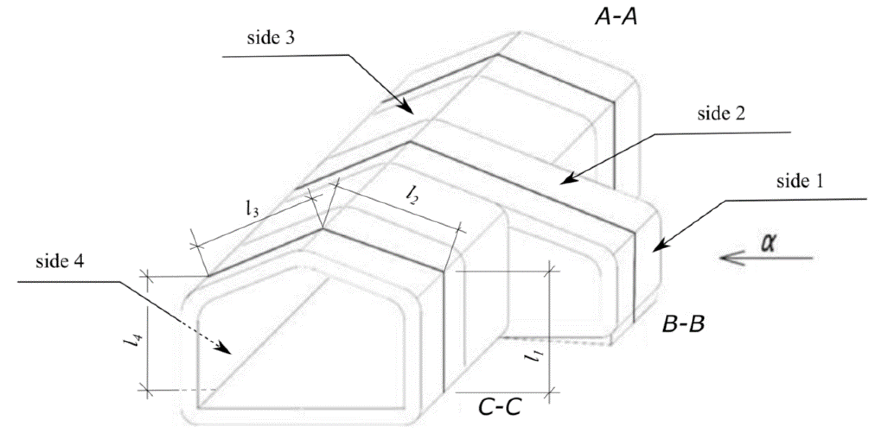
The research was carried out in the direction of the oncoming air flow along the running linear coordinate l in three characteristic sections A-A, B-B and C-C, which are located on flat surfaces side 1, side 2, side 3 and side 4.
As a result, the graphical dependences of the pressure coefficient Cp on the dimensionless coordinate l\L are obtained (Figure 3). It was taken into account that:
where l1, l2, l3 and l4 are linear geometric sizes of corresponding segments.
L = l1 + l2 + l3 + l4
As a result of experimental studies, it was found that on the rear facade of the model (side 4), from the side of the oncoming air flow, there is a vacuum. The minimum value of the pressure coefficient reaches Cp = −0.4 in contrast to the other two sections A-A and C-C, for which these values on the same facade are positive. This can be explained by the originality of the shape of the model block, in particular its convexity in the section B-B. The possibility of installing a thermosyphon solar collector in this section was evaluated and the results of research confirmed this possibility, as evidenced by the fact that the front facade on the side of the oncoming air flow (side 1 and side 2) is supported. In addition, from the graphical dependencies (Figure 3b), you can see that Cpl\L = 0.05 > Cpl\L = 0.56; this will further create the energy potential for air movement in the thermosyphon solar collector, which will be the next stage of research.
To assess the adequacy of the experimental studies, a comparison was made between the obtained data and the results of computer simulations, which were conducted on the ANSYS platform. The information here has been used to validate the velocity and turbulence intensity profile. The model’s dimensions were kept the same to enable comparisons of the different parameters [40,41]. A similar shape of a modular building, which was studied in a wind tunnel, was adopted for modeling. Figure 4 presents diagrams of the distribution of the speed of the oncoming air flow at α = 0° and pressure distribution on the surface of the model.
Presented in Figure 4 are computer simulation results that prove the validity of experimental studies. The pressure distribution on the surface of the computer model is identical to the distribution of the pressure coefficient when studying it in a wind tunnel.
4. Conclusions
- On the side of the oncoming undisturbed air flow with an angle of attack α = 0° on the surface of the facade (side 1), the value of the pressure coefficient gradually increases, reaching a maximum value at the coordinate l\L = 0.15 and decreases when approaching the roof edge (side 2).
- In the windward area of the roof (side 2), pressure coefficients take positive values that range from 0.8 to 1.25. This fluctuation of the values of the coefficient Cp indicates the possibility of tearing off the boundary layer at the edges of the roof surface of the house model.
- In the windward zone on the roof surface (side 3), the value of pressure coefficients acquires negative values in the range −0.23… −0.43.
- For the windward facade of the model (side 4) in sections A-A and C-C, pressure coefficients are positive and range from 0.39 to 0.43. The section B-B is special for this facade, as it is characterized by a rarefaction of −0.27… −0.39, the formation of which can be explained by the elongated shape of the middle segment of the house, which falls on this section.
- The distribution of pressure coefficients obtained as a result of experimental studies in the wind tunnel and computer models of house flow make it possible to assert the effective operation of the thermosyphon solar collector, which can be installed on the windward side of the facade, especially in section B-B.
Author Contributions
Conceptualization, V.Z. and M.U.; methodology, V.Z.; software, M.R.; validation, Y.F., M.A. and M.R.; formal analysis, V.Z.; investigation, M.U.; resources, V.Z.; data curation, M.U.; writing—original draft preparation, Y.F.; writing—review and editing, Y.F.; visualization, M.R.; supervision, M.A.; project administration, V.Z.; funding acquisition, M.U. All authors have read and agreed to the published version of the manuscript.
Funding
This research received no external funding.
Conflicts of Interest
The authors declare no conflict of interest.
References
- Pervez, H.; Ali, Y.; Petrillo, A. A quantitative assessment of greenhouse gas (GHG) emissions from conventional and modular construction: A case of developing country. J. Clean. Prod. 2021, 294, 126210. [Google Scholar] [CrossRef]
- Kamali, M.; Hewage, K.; Sadiq, R. Conventional versus modular construction methods: A comparative cradle-to-gate LCA for residential buildings. Energy Build. 2019, 204, 109479. [Google Scholar] [CrossRef]
- Tavares, V.; Lacerda, N.; Freire, F. Embodied energy and greenhouse gas emissions analysis of a prefabricated modular house: The “Moby” case study. J. Clean. Prod. 2018, 212, 1044–1053. [Google Scholar] [CrossRef]
- Johannes, A.W.H.; van Oorschot, J.A.; Halman, J.I.; Hofman, E. The adoption of green modular innovations in the Dutch housebuilding sector. J. Clean. Prod. 2021, 319, 128524. [Google Scholar] [CrossRef]
- Peltokorpi, A.; Olivieri, H.; Granja, A.D.; Seppänen, O. Categorizing modularization strategies to achieve various objectives of building investments. Constr. Manag. Econ. 2017, 36, 32–48. [Google Scholar] [CrossRef]
- Said, H.M.; Chalasani, T.; Logan, S. Exterior prefabricated panelized walls platform optimization. Autom. Constr. 2017, 76, 1–13. [Google Scholar] [CrossRef]
- Lacey, A.; Chen, W.; Hao, H.; Bi, K. Structural response of modular buildings—An overview. J. Build. Eng. 2018, 16, 45–56. [Google Scholar] [CrossRef] [Green Version]
- Rajanayagam, H.; Poologanathan, K.; Gatheeshgar, P.; Varelis, G.E.; Sherlock, P.; Nagaratnam, B.; Hackney, P. A-State-Of-The-Art review on modular building connections. Structures 2021, 34, 1903–1922. [Google Scholar] [CrossRef]
- Srisangeerthanan, S.; Hashemi, M.J.; Rajeev, P.; Gad, E.; Fernando, S. Review of performance requirements for inter-module connections in multi-story modular buildings. J. Build. Eng. 2019, 28, 101087. [Google Scholar] [CrossRef]
- Chen, Z.; Niu, X.; Liu, J.; Khan, K.; Liu, Y. Seismic study on an innovative fully-bolted beam-column joint in prefabricated modular steel buildings. Eng. Struct. 2021, 234, 111875. [Google Scholar] [CrossRef]
- Zhai, S.-Y.; Lyu, Y.-F.; Cao, K.; Li, G.-Q.; Wang, W.-Y.; Chen, C. Experimental study on bolted-cover plate corner connections for column-supported modular steel buildings. J. Constr. Steel Res. 2021, 189, 107060. [Google Scholar] [CrossRef]
- Aquino, C.D.; Branco, J.M. Experimental evaluation of a modular timber unit filled with insulated corkboard. J. Build. Eng. 2020, 32, 101725. [Google Scholar] [CrossRef]
- Rockwood, D.; da Silva, J.T.; Olsen, S.; Robertson, I.; Tran, T. Design and prototyping of a FRCC modular and climate responsive affordable housing system for underserved people in the pacific island nations. J. Build. Eng. 2015, 4, 268–282. [Google Scholar] [CrossRef]
- Bardhan, R.; Debnath, R. Evaluating building material based thermal comfort of a typical low-cost modular house in India. Mater. Today Proc. 2018, 5, 311–317. [Google Scholar] [CrossRef] [Green Version]
- Gatheeshgar, P.; Poologanathan, K.; Gunalan, S.; Shyha, I.; Sherlock, P.; Rajanayagam, H.; Nagaratnam, B. Development of affordable steel-framed modular buildings for emergency situations (COVID-19). In Structures; Elsevier: Amsterdam, The Netherlands, 2021; pp. 862–875. ISSN 2352-0124. [Google Scholar] [CrossRef]
- Lawson, M.; Ogden, R.; Goodier, C. Design in Modular Construction; CRC Press: Boca Raton, FL, USA, 2014; Volume 476. [Google Scholar] [CrossRef]
- Abdelmageed, S.; Zayed, T. A study of literature in modular integrated construction—Critical review and future directions. J. Clean. Prod. 2020, 277, 124044. [Google Scholar] [CrossRef]
- Pullen, T.; Hall, D.M.; Lessing, J. White Paper: A Preliminary Overview of Emerging Trends for Industrialized Construction in the United States; Center for Integrated Facility Engineering: Stanford, CA, USA, 2019; pp. 1–24. [Google Scholar] [CrossRef]
- Giriunas, K.; Sezen, H.; Dupaix, R.B. Evaluation, modeling, and analysis of shipping container building structures. Eng. Struct. 2012, 43, 48–57. [Google Scholar] [CrossRef] [Green Version]
- Lyu, Y.-F.; Li, G.-Q.; Cao, K.; Zhai, S.-Y.; Wang, Y.-B.; Mao, L.; Ran, M.-M. Bending behavior of splice connection for corner-supported steel modular buildings. Eng. Struct. 2021, 250, 113460. [Google Scholar] [CrossRef]
- Lyu, Y.-F.; Li, G.-Q.; Cao, K.; Zhai, S.-Y.; Li, H.; Chen, C.; Wang, Y.-Z. Behavior of splice connection during transfer of vertical load in full-scale corner-supported modular building. Eng. Struct. 2021, 230, 111698. [Google Scholar] [CrossRef]
- Jȩdrzejuk, H.; Klemm, K.; Marks, W. Multicriteria optimization of buildings arrangement based on wind criteria. Arch. Civ. Eng. 2008, 54, 751–767. [Google Scholar]
- Klemm, K.; Jȩdrzejuk, H.; Marks, W. Application of multicriteria optimization in wind flow analysis. In Proceedings of the 23rd International Conference on Passive and Low Energy Architecture (PLEA 2006), Geneva, Switzerland, 6–8 September 2006. [Google Scholar]
- Ramaji, I.J.; Memari, A.M. Product Architecture Model for Multistory Modular Buildings. J. Constr. Eng. Manag. 2016, 142, 04016047. [Google Scholar] [CrossRef]
- Zhang, J.; Long, Y.; Lv, S.; Xiang, Y. BIM-enabled Modular and Industrialized Construction in China. Procedia Eng. 2016, 145, 1456–1461. [Google Scholar] [CrossRef] [Green Version]
- Hyun, H.; Kim, H.; Lee, H.-S.; Park, M.; Lee, J. Integrated Design Process for Modular Construction Projects to Reduce Rework. Sustainability 2020, 12, 530. [Google Scholar] [CrossRef] [Green Version]
- Schoenborn, J.M. A Case Study Approach to Identifying the Constraints and Barriers to Design, Innovation for Modular Construction. Ph.D. Thesis, Virginia Polytechnic Institute and State University, Blacksburg, VA, USA, 2012. pp. 19–32. Available online: http://hdl.handle.net/10919/32397 (accessed on 27 April 2012).
- Yuan, Z.; Sun, C.; Wang, Y. Design for Manufacture and Assembly-oriented parametric design of prefabricated buildings. Autom. Constr. 2018, 88, 13–22. [Google Scholar] [CrossRef]
- Cao, J.; Bucher, D.F.; Hall, D.M.; Lessing, J. Cross-phase product configurator for modular buildings using kit-of-parts. Autom. Constr. 2021, 123, 103437. [Google Scholar] [CrossRef]
- Aye, L.; Ngo, T.; Crawford, R.H.; Gammampila, R.; Mendis, P. Life cycle greenhouse gas emissions and energy analysis of prefabricated reusable building modules. Energy Build. 2012, 47, 159–168. [Google Scholar] [CrossRef]
- Kamali, M.; Hewage, K. Life cycle performance of modular buildings: A critical review. Renew. Sustain. Energy Rev. 2016, 62, 1171–1183. [Google Scholar] [CrossRef]
- Li, Z.; Zhang, D.; Li, C. Experimental evaluation of indoor thermal environment with modularity radiant heating in low energy buildings. Int. J. Refrig. 2020, 123, 159–168. [Google Scholar] [CrossRef]
- Zhelykh, V.; Venhryn, I.; Kozak, K.; Shapoval, S. Solar collectors integrated into transparent facades. Prod. Eng. Arch. 2020, 26, 84–87. [Google Scholar] [CrossRef]
- Kapalo, P.; Klymenko, H.; Zhelykh, Z.; Adamski, M. Investigation of indoor air quality in the selected ukraine classroom–case study. In Proceedings of the International Conference Current Issues of Civil and Environmental Engineering Lviv-Košice–Rzeszów; Springer: Cham, Switzerland, 2019; ISBN 978-3-030-27010-0. Electronic ISBN: 978-3-030-27011-7. [Google Scholar]
- Wills, J.; Lee, B.; Wyatt, T. A model of wind-borne debris damage. J. Wind Eng. Ind. Aerodyn. 2002, 90, 555–565. [Google Scholar] [CrossRef]
- Peng, J.; Hou, C.; Shen, L. Numerical analysis of corner-supported composite modular buildings under wind actions. J. Constr. Steel Res. 2021, 187, 106942. [Google Scholar] [CrossRef]
- Chen, W.; Hao, H.; Du, H. Failure analysis of corrugated panel subjected to windborne debris impacts. Eng. Fail. Anal. 2014, 44, 229–249. [Google Scholar] [CrossRef]
- Chen, W.; Hao, H. Experimental and numerical study of composite lightweight structural insulated panel with expanded polystyrene core against windborne debris impacts. Mater. Des. 2014, 60, 409–423. [Google Scholar] [CrossRef] [Green Version]
- Barbolini, F.; Cappellacci, P.; Guardigli, L. A Design Strategy to Reach nZEB Standards Integrating Energy Efficiency Measures and Passive Energy Use. Energy Procedia 2017, 111, 205–214. [Google Scholar] [CrossRef]
- Singh, J.; Roy, A.K. Effects of roof slope and wind direction on wind pressure distribution on the roof of a square plan pyramidal low-rise building using CFD simulation. Int. J. Adv. Struct. Eng. 2019, 11, 231–254. [Google Scholar] [CrossRef] [Green Version]
- Sanyal, P.; Dalui, S.K. Effects of courtyard and opening on a rectangular plan shaped tall building under wind load. Int. J. Adv. Struct. Eng. 2018, 10, 169–188. [Google Scholar] [CrossRef] [Green Version]
Figure 1.
Photo of a model of a modular house in the working part wind tunnel: (a) scheme of experimental setup; (b) 1—working part of the wind tunnel; 2—nozzle; 3—leveling grid; 4—prechamber; 5—diffuser; 6—model of the house; 7—underlying surface of the model; 8—drainage points (static pressure selection); 9—flexible tubes; 10—micromanometers MMN.


Figure 2.
Characteristic cross sections A-A, B-B and C-C for conducting experimental studies on the model in the direction of the oncoming wind flow α = 0°.
Figure 2.
Characteristic cross sections A-A, B-B and C-C for conducting experimental studies on the model in the direction of the oncoming wind flow α = 0°.

Figure 3.
Dependences of the pressure coefficient Cp on the dimensionless coordinate l\L: (a) for cutting A-A; (b) for cutting B-B; (c) for cutting C-C.
Figure 3.
Dependences of the pressure coefficient Cp on the dimensionless coordinate l\L: (a) for cutting A-A; (b) for cutting B-B; (c) for cutting C-C.

Figure 4.
Distribution of air flow velocity, m/s (a,b) and pressure, Pa (c) on the surface of the model of the house when flowing undisturbed air flow at the angle of attack α = 0°.
Figure 4.
Distribution of air flow velocity, m/s (a,b) and pressure, Pa (c) on the surface of the model of the house when flowing undisturbed air flow at the angle of attack α = 0°.


Table 1.
Devices for research and their technical characteristics.
| № | Name of Measuring Instruments | Characteristics |
|---|---|---|
| 1 | Pito-Prantle nozzle №77 | Ζ = 0.983 sensitivity ± 50 |
| 2 | Barometer-aneroid BAMM №8795 | 80,000–106,000 Pa Precision ± 200 Pa |
| 3 | Aspiration psychrometer №20922 | Precision ± 0.1 °C |
| 4 | High-pressure nozzle D = 0.8 mm | Ζ = 0.99 |
| 5 | Micromanometer MMN-24001.0 №2000 i №2200 | Precision ± 0.5 mm |
Publisher’s Note: MDPI stays neutral with regard to jurisdictional claims in published maps and institutional affiliations. |
© 2022 by the authors. Licensee MDPI, Basel, Switzerland. This article is an open access article distributed under the terms and conditions of the Creative Commons Attribution (CC BY) license (https://creativecommons.org/licenses/by/4.0/).
Share and Cite
MDPI and ACS Style
Zhelykh, V.; Ulewicz, M.; Furdas, Y.; Adamski, M.; Rebman, M. Investigation of Pressure Coefficient Distribution on the Surface of a Modular Building. Energies 2022, 15, 4644. https://doi.org/10.3390/en15134644
AMA Style
Zhelykh V, Ulewicz M, Furdas Y, Adamski M, Rebman M. Investigation of Pressure Coefficient Distribution on the Surface of a Modular Building. Energies. 2022; 15(13):4644. https://doi.org/10.3390/en15134644
Chicago/Turabian StyleZhelykh, Vasyl, Małgorzata Ulewicz, Yurii Furdas, Mariusz Adamski, and Maksym Rebman. 2022. "Investigation of Pressure Coefficient Distribution on the Surface of a Modular Building" Energies 15, no. 13: 4644. https://doi.org/10.3390/en15134644
Note that from the first issue of 2016, this journal uses article numbers instead of page numbers. See further details here.