Design and Analysis of Optimal Current Vector for HTS-Based Multi-Input Wireless Power Transfer Systems


Department of Electrical and Electronic Engineering, The University of Hong Kong, Hong Kong, China
*
Author to whom correspondence should be addressed.
Energies 2022, 15(12), 4337; https://doi.org/10.3390/en15124337
Submission received: 18 May 2022
/
Revised: 6 June 2022
/
Accepted: 10 June 2022
/
Published: 14 June 2022
(This article belongs to the Section F3: Power Electronics)
Abstract
:This paper presents a newly-designed optimal current algorithm for high-temperature superconductor (HTS)-based multi-input wireless power transfer (WPT) systems. In this way, both high controllability and lower AC losses can be achieved in the proposed systems, and they are especially superior for long-range and long-time operations. Simplified AC loss modeling for HTS windings is developed for the designed transmitter coils. The accordant optimal current vector is derived and analyzed in order to achieve the highest output power and the lowest primary AC losses. With the proper current control of multiple transmitters and the use of a designed HTS coupler, the system controllability can be greatly improved compared with conventional WPT systems. Based on the information on the impedance characteristics on the primary side, the magnetic field generated by different transmitters can be maximized at the target position. Thus, the maximum output power tracking can be realized with a relatively long transmission distance and a low coupling coefficient. Both active and passive solutions are designed and presented to deal with the cross-coupling issue in multi-input WPT systems. For numerical validation, a practical prototype of the HTS couplers is fabricated. An experimental platform is established with a liquid nitrogen cooling system. The test results further validate the feasibility and the high controllability of the proposed system.
1. Introduction
Magnetic coupling resonance-based wireless power transfer (WPT) systems have drawn considerable attention and research interest recently for their high embeddability and great convenience [1,2,3]. Undoubtedly, WPT is gradually becoming one of the most prominent technologies in future industrial applications [4,5]. With its rapid development, modern industrial applications have placed more requirements on this technology for higher convenience and flexibility in control [6,7]. However, for conventional one-to-one WPT systems, the coupling strength between the transmitter and receiver coils will be highly sensitive to their relative position relationships [8]. Even slight lateral or angular misalignments will cause great output decay [9,10]. Stemming from this, a conventional one-to-one system will only be suitable for static wireless power transfer [11], and the transmission distance will also be highly limited [12]. On the other hand, the lack of controllability means that it may not be able to further satisfy some special working requirements. For example, dynamic charging systems require an extraordinarily good fault-tolerance ability [13,14,15]. Multi-output systems should be designed with consideration of output power distribution on the secondary side [16,17,18]. Therefore, more controllable and flexible systems with multiple input currents are gradually becoming a future development trend of WPT technology.
1.1. Related Surveys
As mentioned before, multi-input WPT systems can be regarded as a viable solution to effectively increase the system controllability as well as the output performance [19,20,21]. By breaking the traditional single large coil into a small transmitter coil array or matrix, the system gives us a greater degree of freedom in control, and thus its flexibility can be greatly improved. With the proper current algorithm [22,23,24], the system can maximize the resonant magnetic field at one or multiple target positions in order to achieve the best output performance. As a result, both the transmission distance and fault tolerance ability of the system can be effectively improved. However, in many previous works, the optimal current vector usually required a complex algorithm, as well as impedance matching schemes, which brings a heavy burden for optimization and the system design [25,26]. Another key problem in most long-distance WPT lies in the fact that the heating loss consumed at the primary side becomes comparable to the power transmitted. It has already been proven by many previous research works that HTS-based coupler coils will be superior to traditional copper coils in transmission efficiency, especially for long-time operations [27,28,29]. However, very few of these studies focused on multi-coupling WPT systems and their accordant current algorithm. By using HTS-based coupler coils, the traditional heating loss calculation model that only considers the parasite resistance will no longer be suitable. Under the superconducting condition, the resistance of the winding can be considered to be zero, and AC losses will become the dominant components. Thus, the AC loss modeling for HTS coils and the accordant optimal current algorithm for HTS-based multi-input WPT systems still deserves further in-depth research.
1.2. Contributions of This Study
Based on the above-mentioned problems, this paper designs and analyzes the most convenient optimal current vector according to simplified AC loss modeling for HTS coils. As a result, the maximum output power tracking can be realized with multiple-current control. Both a near-field high-power-level system and a far-field low-power-level system are presented and analyzed in order to validate the effectiveness of the proposed optimal current vector. To deal with the cross-coupling effect between the multiple transmitters, two different solutions are presented and discussed in order to realize muti-current synchronization. Both the simulation and experimental results validate the supposition that the proposed current control can perfectly meet the requirements of good output performance, high controllability, and a high fault-tolerant ability for long-range wireless power transfer.
1.3. Organization of This Paper
Section 2 presents the system modeling, proposed optimal current algorithm, and the system implementations. Simulations for the proposed system with different receiver configurations and transmission ranges are conducted. The accordant results are presented and analyzed in Section 3. In Section 4, multiple HTS transmitter coils are fabricated, and the experimental platform is established with a liquid nitrogen cooling system. The system performance is practically tested and analyzed. Finally, a conclusion is drawn in Section 5.
2. Design Scheme
2.1. AC Loss Modelling for the HTS Winding
The designed HTS winding configuration is depicted in Figure 1, where t and w denote the thickness and width of the tape, respectively; tm is the thickness of the metal layer; d is the inter-turn gap; and It is the transport current. Each turn of the winding can be simplified and regarded as a stack of superconductive (SC) material with a ferromagnetic substrate as the stabilizer or reinforcing layer [30,31]. When the operating frequency is low enough and the transport current is much less than the critical current, which is denoted by Ic, the hysteresis loss and eddy current loss per tape per length per cycle can be expressed as [31]
where ρ denotes the electrical resistivity, f denotes the operation frequency, and F and G denote two different integration functions of (d/w) and (It/Ic), respectively. As can be observed, the eddy current loss increases with the operating frequency. However, if the operating frequency and transport current are all within the limit, the current conducting in the SC layer will strongly shield the metal layer; thus, the hysteresis loss will dominate the AC loss components, and the eddy current loss can be neglected for simplicity [32,33]. The critical current of the SC material is determined by its inherent property, and the frequency limit can be estimated by [30]
Under the condition that the metal layer has the same width as the SC layer, F~ for It << Ic [31]. Assuming that the material is distributed homogeneously in each unit length of the winding, the total averaged AC power loss of the designed transmitter coil can be approximately obtained through
where Chyst denotes the constant coefficient, the value of which is determined by the critical current, winding material, and system configurations.
2.2. Optimal Current Algorithm
Different compensation topologies can be applied in multi-input WPT systems. The most simplified one is the series-to-series (SS) architecture, the equivalent circuit of which is shown in Figure 2a. In the fully compensated situation, the reactive part of the impedance for each circuit loop should equal zero. For a system with n transmitters, it should be satisfied that
where ω denotes the angular frequency of the system. Based on the previous analysis, the system equations can be expressed as
where Itp and Utp denote the input current and input voltage of the pth transmitter, respectively; Mtpi denotes the mutual inductance between the pth and ith transmitter coils; Mri is the mutual inductance between the ith transmitter and receiver coils; and Ir and Zr denote the receiver current and total impedance of the receiver circuit, respectively. The output power is given by
where Rl denotes the equivalent load resistance. In order to obtain the optimal vector of the transmitter currents, the signal-noise-ratio (SNR) of the system, namely the ratio between the power transmitted to the receiver and the power loss at the primary side, is given by
Apparently, Iti cannot all equal zero. Thus, (8) can be considered as a continuous function involving multi-variables Iti. In order to reach the highest SNR, for the pth transmitter current, it should be satisfied that
which yields
Assuming that the base current is denoted by Ibase, (10) can be further expressed as
Hence, the output power of the system can be obtained through
In practical applications, it is not always easy to obtain data from the secondary side. However, based on (11), the optimal vector of the multi-input currents can be acquired only through the mutual inductance ratios, and their absolute values are not necessarily needed. It can be derived from (6) that
As depicted in (13), for the fixed system configuration, the mutual inductance ratio between the receiver and each transmitter coil can be conveniently obtained and calculated through the input currents and voltages of the primary side. Thus, the optimal current vector can be calculated and scaled through (11). Therefore, no extra communication system will be needed from the secondary side. Another critical issue is that the calculated input currents should always be in-phase or opposite-phase for more efficient operation [34], while in SS-type multi-input WPT systems, the mutual inductances between the transmitter coils will cause the undesired phase shifting of the input currents. This problem can be neglected when the mutual inductance between the transmitter coils is weak enough. However, with a system configuration in which the transmitter coils are relatively strongly coupled, a phase synchronization process will become necessary. An efficient method to solve this problem is to delay a certain angle for each control signal, as given by
Another effective way to automatically realize current synchronization is to use individual high-order compensations to create a constant current output for each transmitter, as depicted in Figure 2b. As can be seen, the system design requires only passive electric components, and the active phase correction process will no longer be needed anymore. Under the fully-compensated condition given by (15), the LCC topology forms a double-resonant circuit, and can thereby achieve a constant current output for each inverter, as shown in (16) [35,36]. As a result, with the synchronized input signal, the multiple transmitter currents will be perfectly synchronized, with no error. However, a tradeoff exists in that the extra inductors may bring more conduction losses. For a system with too many transmitter coils, the design complexity will also be inevitably increased.
2.3. Coil Design
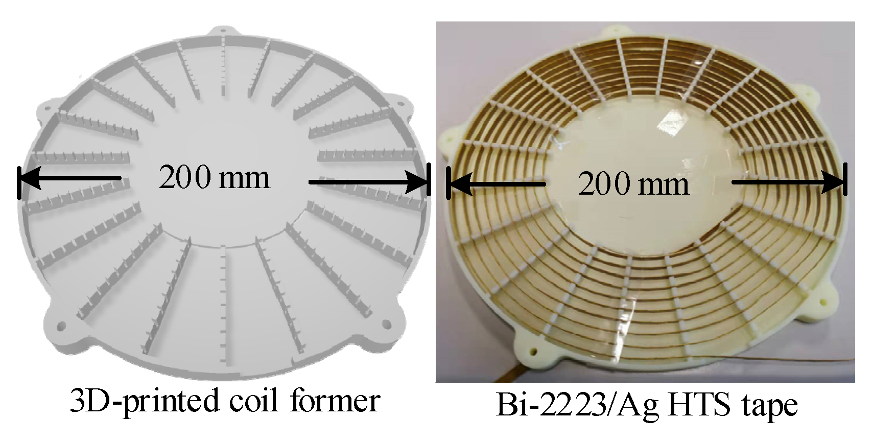
In this work, Bi-2223/Ag is adopted as the tape material for the prototype fabrication. The critical current is 50 A and the estimated frequency limit is higher than 1 MHz. As discussed in [32], with the inter-turn gap increases, the AC losses will converge to the same value, as the winding is in the isolated single-turn condition, and this value will be achieved approximately when the gap equals the tape width. Here, we chose 4.5 mm as the gap distance for the tape width of 4 mm in order to minimize the AC losses as much as possible. In order to satisfy the requirement that the coil winding should be homogeneously fabricated with the equaled gap and radius for each transmitter, and to protect the tape material from being overly bent or twisted, a coil former with equal-gapped fixing slits along its axial directions was designed and printed. Its 3D model and the realized fabrication of the HTS transmitters are shown in Figure 3. The practical configuration of the transmitter coil is listed in Table 1. Several critical points are worth mentioning in the coil designs. Firstly, the inner radius needs to be greater than the minimum allowed bending radius (here, this threshold is 40 mm), in order to make sure that the insulation layer is not damaged. Secondly, the intern gap should be large enough that every single turn of the winding can be sufficiently cooled by the liquid nitrogen. What is more, an apparent tradeoff exists in the coupling coefficient and the AC loss control. Under the condition of the above-mentioned criteria, the larger coverage area of the coil means a longer tape length will be needed; as a result, the transport losses will naturally be increased, especially for a relatively high operation frequency. For the designed winding, the measured results of the transport current losses versus the input current under the frequency of 100 kHz are presented in Figure 4. As can be seen, every increased turn will bring an accordant incremental quantity in primary AC losses [28]. This will have a considerable impact on the system efficiency, especially for the low-power-level applications. Therefore, in practice, different aspects should be considered in the transmitter coil design, including the rated transport current, the operation frequency, the transmission distance, and the configuration of the receiver coils, etc.
3. System Performance
The magnetic profiles of the system with two transmitters and one receiver were evaluated using the finite element method (FEM), and the results are presented in Figure 5 and Figure 6. In order to adapt to different working scenarios, two Litz wire-fabricated receivers with different coil sizes were designed, as described in Figure 5a and Figure 6a, respectively. The turn numbers of the two receivers were 20 and 30, respectively. The receiver with the bigger coil size (Rx 1) is designed to pick up a relatively higher output power while the smaller receiver coil (Rx 2) was designed for long-range low-power-level applications such as medical implants or undersea sensor networks. Because these appliances normally have very low power consumption [37,38], for each charging cycle, the charging energy will be enough for these devices to operate for a relatively long time. Thus, the system functionality weighs much more than the efficiency. Therefore, the acceptable transmission distance for these working scenarios can be relatively longer. FEM simulations for both systems were conducted under the operation frequency of 100 kHz [39,40]. The equivalent load resistances are 5 Ω and 50 Ω for Rx 1 and Rx 2, respectively. As depicted in Figure 5 and Figure 6, the proposed optimal current vector performs well for both receivers with different configurations. Compared with the conventional one-to-one WPT system, the use of multiple transmitters can effectively reduce the input voltage pressure for each coil and strengthen the magnetic field at the target position in order to reach the desired output power. Under the condition that the transmitter currents are synchronized to each other, the output current induced on the secondary side lags the input current by 90°. The maximum point of the magnetic flux density generated at the Rx 1 coil is 46.4 mT, which is stronger than that at the Rx 2 coil by over 300 times, and the ratio between the received power for the two systems is about 35:1. The magnetic profile for the equaled or unequaled coupling coefficient between Rx 2 and the two transmitters is compared in Figure 6b and Figure 6c, respectively. The comparison was conducted under the condition with the same AC power losses consumed at the primary side. The input current ratio was calculated by (10), and the output power ratio between the two cases was 1.2:1. Based on the symmetric property of the system configuration, the proposed current control can realize the maximum output power tracking for different position relationships between the receiver and the transmitters with a relatively low fluctuation of output power.
4. Experimental Validation
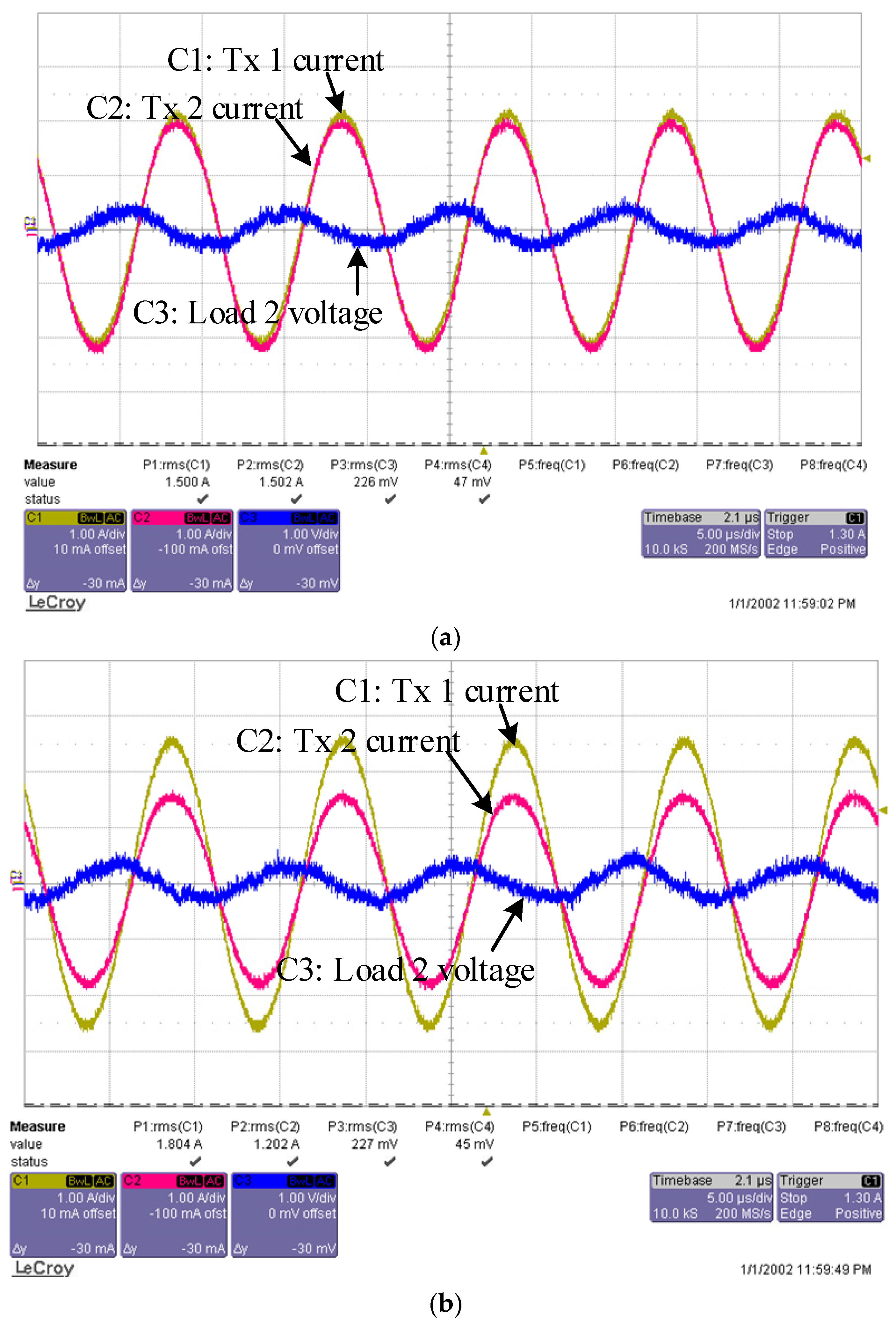
In order to further validate the practical performance of the proposed system, a practical prototype was built, and the measurement platform was established as shown in Figure 7. Two designed transmitters were placed in a Styrofoam container and cooled by a liquid nitrogen bath. The measured system parameters are presented in Table 2. As with the simulation model, the two receivers were fabricated with Litz wire, with 20 single-layer turns (Rx 1) and 30 double-layer turns (Rx 2), respectively. The transmission distances for the two receivers were 100 mm and 300 mm, respectively. The measured input and output waveforms for the two receivers are presented as shown in Figure 8 and Figure 9, respectively. As depicted, the two transmitters are input with identical 1.5 A currents, and can always be synchronized to each other. Because of the strengthened magnetic field, the output power was slightly increased when the transmitter coil was under superconducting conditions, compared to room-temperature operation.
For the long-distance working scenario, Rx 2 successfully picks up a certain amount of power with a distance over 12 times its radius. The output power can remain constant for different receiver positions with the proper current control. The system power distribution for Rx 1 is analysed as presented in Figure 10. The transmitter prototype adopted in the experiments is relatively small, with only 10 turns. The critical current is also not big enough. However, in practical applications, the fabrication can be greatly improved for a higher transport current, larger transmitter coil sizes, and many more turns. Thus, there is the potential to utilize the proposed system for longer transmission distances, as well as higher output powers.
5. Conclusions
Based on the energy beam-forming technology, this paper presents an optimal current vector for HTS multi-input WPT systems. Bi-2223/Ag HTS material is utilized in the coupler coil design to improve the system performance. Firstly, tractable AC loss modeling for the HTS material is established, based on which the accordant optimal current algorithm for multiple transmitters is designed and proposed. By using the information on different input impedance characteristics of the transmitters, the optimal current vector can be obtained in order to realize the maximum output power tracking for different receiver positions. All of the measurements can be conducted from the primary side, and there is no need for extra information feedback from the receiver. The FEA results suggest that the magnetic field generated by the multiple transmitter currents can be maximized at the target positions. For implementation, two different solutions were presented in this paper to solve the cross-coupling problem which will be commonly encountered in multi-input WPT systems. Additionally, practical prototypes of the system were built for different receiver configurations. The accordant experimental platform was established with a liquid nitrogen cooling system for practical tests. The results further validate the effectiveness of the proposed system, as well as its feasibility in practical applications.
Author Contributions
Conceptualization, methodology, software, and writing—original draft preparation, X.T.; investigation, validation and data curation, X.T. and W.L.; resources and supervision, K.T.C. All authors have read and agreed to the published version of the manuscript.
Funding
This research received a grant from the Hong Kong Research Grants Council, Hong Kong Special Administrative Region, China (Project No. T23-701/20-R).
Institutional Review Board Statement
Not applicable.
Informed Consent Statement
Not applicable.
Data Availability Statement
Not applicable.
Conflicts of Interest
The authors declare no conflict of interest.
Abbreviations
| Qhyst | Hysteresis loss per cycle |
| Qeddy | Eddy current loss per cycle |
| t | Tape thickness |
| tm | Metal layer thickness of the tape |
| w | Tape width |
| d | Innerturn gap |
| It | Transport current |
| Ic | Critical current |
| fc | Critical frequency |
| Chyst | Constant coefficient for hysteresis loss estimation |
| ω | System angular frequency |
| Ut | Input voltage |
| Mtpi | Mutual inductance between the pth and ith transmitter coils |
| Mrp | Mutual inductance between the receiver coil and the pth transmitter coil |
| Lt | Transmitter inductance |
| Ct | Compensated capacitor for a transmitter in series resonance |
| Ls | Series-connected inductor in the LCC-S topology |
| Cp | Parallel-connected capacitor in the LCC-S topology |
| Ct | Series-connected capacitor in the LCC-S topology |
| Lr | Receiver inductance |
| Cr | Compensated capacitor for the receiver |
| Ir | Compensated capacitor for the receiver |
| Zr | Secondary impedance |
| Rl | Equivalent load resistance |
| γ | Signal noise ratio |
| Ibase | Base current for the optimal current vector |
| φtp | Phase correction angle for the pth input signal in the SS topology |
References
- Clerckx, B.; Huang, K.; Varshney, L.R.; Ulukus, S.; Alouini, M.-S. Wireless power transfer for future networks: Signal processing, machine learning, computing, and sensing. IEEE J. Sel. Top. Signal Process. 2021, 15, 1060–1094. [Google Scholar] [CrossRef]
- Jiang, C.; Chau, K.T.; Leung, Y.Y.; Liu, C.; Lee, C.H.T.; Han, W. Design and analysis of wireless ballastless fluorescent lighting. IEEE Trans. Ind. Electron. 2019, 66, 4065–4074. [Google Scholar] [CrossRef]
- Han, W.; Chau, K.T.; Zhang, Z. Flexible induction heating using magnetic resonant coupling. IEEE Trans. Ind. Electron. 2017, 64, 1982–1992. [Google Scholar] [CrossRef]
- Tian, X.; Chau, K.T.; Han, W.; Lee, C.H.T. Design and analysis of double-layer electromagnetic field limiter for wireless rechargeable medical implants. IEEE Trans. Magn. 2021, 57, 5100206. [Google Scholar] [CrossRef]
- Liu, W.; Chau, K.T.; Chow, C.C.T.; Lee, C.H.T. Wireless energy trading in traffic internet. IEEE Trans. Power Electron. 2022, 37, 4831–4841. [Google Scholar] [CrossRef]
- Huang, Y.; Liu, C.; Xiao, Y.; Liu, S. Separate power allocation and control method based on multiple power channels for wireless power transfer. IEEE Trans. Power Electron. 2020, 35, 9046–9056. [Google Scholar] [CrossRef]
- Lee, H.-S.; Lee, J.-W. Adaptive wireless power transfer beam scheduling for non-static IoT devices using deep reinforcement learning. IEEE Access 2020, 8, 206659–206673. [Google Scholar] [CrossRef]
- Tian, X.; Chau, K.T.; Han, W.; Lee, C.H.T. Analysis of multi-coil omnidirectional energy harvester. IEEE Trans. Magn. 2021, 57, 8000806. [Google Scholar] [CrossRef]
- Wen, F.; Chu, X.; Li, Q.; Zhao, W.; Zhu, X.; Wu, Y. Receiver localization strategy of wireless charging system based on mutual inductance disturbance. IEEE Trans. Appl. Supercond. 2021, 31, 0600604. [Google Scholar] [CrossRef]
- Qian, L.; Chen, M.; Cui, K.; Shi, G.; Wang, J.; Xia, Y. Modeling of mutual inductance between two misalignment planar coils in wireless power transfer. IEEE Microw. Wirel. Compon. Lett. 2020, 30, 814–817. [Google Scholar] [CrossRef]
- Shu, X.; Zhang, B.; Wei, Z.; Rong, C.; Sun, S. Extended-distance wireless power transfer system with constant output power and transfer efficiency based on parity-time-symmetric principle. IEEE Trans. Power Electron. 2021, 36, 8861–8871. [Google Scholar] [CrossRef]
- Dong, Z.; Liu, S.; Li, X.; Xu, Z.; Yang, L. A novel long-distance wireless power transfer system with constant current output based on domino-resonator. IEEE J. Emerg. Sel. Top. Power Electron. 2021, 9, 2343–2355. [Google Scholar] [CrossRef]
- Fujita, T.; Yasuda, T.; Akagi, H. A dynamic wireless power transfer system applicable to a stationary system. IEEE Trans. Ind. Appl. 2017, 53, 3748–3757. [Google Scholar] [CrossRef]
- Zhang, Z.; Chau, K.T. Homogeneous wireless power transfer for move-and-charge. IEEE Trans. Power Electron. 2015, 30, 6213–6220. [Google Scholar] [CrossRef]
- Dai, X.; Jiang, J.; Wu, J. Charging area determining and power enhancement method for multiexcitation unit configuration of wirelessly dynamic charging EV system. IEEE Trans. Ind. Electron. 2019, 66, 4086–4096. [Google Scholar] [CrossRef]
- Tian, X.; Chau, K.T.; Pang, H.; Liu, W. Power adaption design for multifrequency wireless power transfer system. IEEE Trans. Magn. 2021. [Google Scholar] [CrossRef]
- Tian, X.; Chau, K.T.; Hua, Z.; Han, W. Design and analysis of demand-customized selective wireless power transfer system. IEEE Trans. Ind. Electron. 2022. [Google Scholar] [CrossRef]
- Zhong, W.; Hui, S.Y.R. Auxiliary circuits for power flow control in multifrequency wireless power transfer systems with multiple receivers. IEEE Trans. Power Electron. 2015, 30, 5902–5910. [Google Scholar] [CrossRef]
- Kim, M.W.; Kim, J.H.; Cho, Y.; Kim, M.; Choi, B.H.; Lee, K.; Kim, J.; Cho, G.H.; Rim, C.T. High-resolution synthesized magnetic field focusing for RF barcode applications. IEEE Trans. Ind. Electron. 2018, 65, 597–607. [Google Scholar] [CrossRef]
- Kim, J.H.; Choi, B.H.; Kit, H.R.; Rim, C.T. 2-D synthesized magnetic field focusing technology with loop coils distributed in a rectangular formulation. IEEE Trans. Power Electron. 2019, 66, 5558–5566. [Google Scholar] [CrossRef]
- Asiful Huda, S.M.; Arafat, M.Y.; Moh, S. Wireless power transfer in wirelessly powered sensor networks: A Review of recent progress. Sensors 2022, 22, 2952. [Google Scholar] [CrossRef] [PubMed]
- Jung, H.; Lee, B. Optimization of magnetic field focusing and null steering for selective wireless power transfer. IEEE Trans. Power Electron. 2020, 35, 4622–4633. [Google Scholar] [CrossRef]
- Zhao, Y.; Li, X.; Ji, Y.; Xu, C. Random energy beamforming for magnetic MIMO wireless power transfer system. IEEE Internet Things J. 2020, 7, 1773–1787. [Google Scholar] [CrossRef]
- Yang, G.; Moghadam, M.R.V.; Zhang, R. Magnetic MIMO signal processing and optimization for wireless power transfer. IEEE Trans. Signal Process. 2017, 65, 2860–2874. [Google Scholar] [CrossRef] [Green Version]
- Tang, W.; Zhu, Q.; Yang, J.; Song, D.; Su, M.; Zou, R. Simultaneous 3-D wireless power transfer to multiple moving devices with different power demands. IEEE Trans. Power Electron. 2020, 35, 4533–4546. [Google Scholar] [CrossRef]
- Lu, Z.; Zhao, Y.; Liu, D. Adaptive impedance matching scheme for magnetic MIMO wireless power transfer system. Electronics 2021, 10, 2788. [Google Scholar] [CrossRef]
- Hwang, Y.J.; Jang, J.Y. Design and characteristic analysis of an inductive link for wireless current charging of a HTS magnet. IEEE Trans. Appl. Supercond. 2022, 32, 4600905. [Google Scholar] [CrossRef]
- Philip, M.; Zhang, H.; Kails, K.; Li, Q. Loss characteristics of superconducting pancake, solenoid and spiral coils for wireless power transfer. Supercond. Sci. Technol. 2020, 33, 074008. [Google Scholar]
- Chung, Y.D.; Lee, C.Y.; Kang, H.K.; Park, Y.G. Design consideration and efficiency comparison of wireless power transfer with HTS and cooled copper antennas for electric vehicle. IEEE Trans. Appl. Supercond. 2015, 25, 5000205. [Google Scholar] [CrossRef]
- Grilli, F.; Pardo, E.; Stenvall, A.; Nguyen, D.N.; Yuan, W.; Gömöry, F. Computation of losses in HTS under the action of varying magnetic fields and currents. IEEE Trans. Appl. Supercond. 2014, 24, 78–110. [Google Scholar] [CrossRef]
- Müller, K.-H. AC losses in stacks and arrays of YBCO/Hastelloy and monofilamentary Bi-2223/Ag tapes. Phys. C Supercond. 1999, 312, 149–167. [Google Scholar] [CrossRef]
- Utschick, C.; Som, C.; Šouc, J.; Große, V.; Gömöry, F.; Gross, R. Superconducting wireless power transfer beyond 5 kW at high power density for industrial applications and fast battery charging. IEEE Trans. Appl. Supercond. 2021, 31, 5500110. [Google Scholar] [CrossRef]
- Jiang, Z.; Long, N.J.; Staines, M.; Li, Q.; Slade, R.A.; Amemiya, N.; Caplin, A.D. Transport AC loss measurements in single- and two-layer parallel coated conductor arrays with low turn numbers. IEEE Trans. Appl. Supercond. 2012, 32, 8200306. [Google Scholar] [CrossRef]
- Tian, X.; Chau, K.T.; Liu, W.; Lee, C.H.T. Selective wireless power transfer using magnetic field editing. IEEE Trans. Power Electron. 2019, 66, 245–254. [Google Scholar] [CrossRef]
- Zhu, Q.; Wang, L.; Guo, Y.; Liao, C.; Li, F. Applying LCC compensation network to dynamic wireless EV charging system. IEEE Trans. Ind. Electron. 2016, 63, 6557–6567. [Google Scholar] [CrossRef]
- Tian, X.; Chau, K.T.; Liu, W.; Pang, H.; Lee, C.H.T. Maximum power tracking for magnetic field editing based omnidirectional wireless power transfer. IEEE Trans. Power Electronics. 2022. [Google Scholar] [CrossRef]
- Aslam, N.; Xia, K.; Hadi, M.U. Optimal wireless charging inclusive of intellectual routing based on SARSA learning in renewable wireless sensor networks. IEEE Sens. J. 2019, 19, 8340–8351. [Google Scholar] [CrossRef]
- Chen, J.C.; Kan, P.; Yu, Z.; Alrashdan, F.; Garcia, R.; Singer, A.; Lai, C.S.; Avants, B.; Crosby, S.; Li, Z.; et al. A wireless millimetric magnetoelectric implant for the endovascular stimulation of peripheral nerves. Nat. Biomed. Eng. 2022. [Google Scholar] [CrossRef]
- He, Y.; Wang, Y.; Nie, X.; Chen, W.; Yan, Z. High-temperature superconducting capacitor and its application to a superconducting wireless power transfer system. IEEE Trans. Appl. Supercond. 2019, 29, 5000207. [Google Scholar] [CrossRef]
- Chung, Y.D.; Lee, C.Y.; Kim, D.W.; Kang, H.; Park, Y.G.; Yoon, Y.S. Conceptual design and operating characteristics of multi-resonance antennas in the wireless power charging system for superconducting MAGLEV train. IEEE Trans. Appl. Supercond. 2017, 27, 3601805. [Google Scholar] [CrossRef]
Figure 1.
Simplified HTS winding configuration.

Figure 2.
Equivalent circuit of a multi-input WPT system. (a) SS topology; (b) LCC-S topology.

Figure 3.
Coil design.

Figure 4.
Transport current losses under a 100 kHz operation frequency.

Figure 5.
FEM results for a large receiver coil. (a) System configuration; (b) magnetic profile.


Figure 6.
FEM results for a small receiver coil. (a) System configuration; (b) magnetic profile with a center-positioned receiver; (c) magnetic profile with an off-center-positioned receiver.
Figure 6.
FEM results for a small receiver coil. (a) System configuration; (b) magnetic profile with a center-positioned receiver; (c) magnetic profile with an off-center-positioned receiver.

Figure 7.
Experimental platform.

Figure 8.
Measured waveforms for Rx 1. (a) Room-temperature environment; (b) liquid nitrogen environment.
Figure 8.
Measured waveforms for Rx 1. (a) Room-temperature environment; (b) liquid nitrogen environment.

Figure 9.
Measured waveforms for Rx 2. (a) Center-positioned; (b) off-center-positioned.

Figure 10.
Power analysis.


Table 1.
Parameters of the transmitter coils.
| Items | Value |
|---|---|
| Material (SC/metal) | Bi-2223/Ag |
| Thickness × width (t × w) | 0.5 × 4 mm |
| Number of turns | 10 |
| Inner radius | 53 mm |
| Interturn gap (d) | 4.5 mm |
| Outer radius | 98 mm |
| Total length | 4.2 m |
| Inductance (averaged) | 20.4 μH |
Table 2.
Measured system parameters.
| Items | Value |
|---|---|
| Inductance of Rx 1 | 208.5 μH |
| Compensated capacitor for Rx 1 | 12.1 nF |
| Resistance of Rx 1 | 0.3 Ω |
| Load resistor 1 | 5 Ω |
| Inductance of Rx 2 | 36.6 μH |
| Compensated capacitor for Rx 2 | 69.2 nF |
| Resistance of Rx 2 | 0.5 Ω |
| Load resistor 2 | 50 Ω |
Publisher’s Note: MDPI stays neutral with regard to jurisdictional claims in published maps and institutional affiliations. |
© 2022 by the authors. Licensee MDPI, Basel, Switzerland. This article is an open access article distributed under the terms and conditions of the Creative Commons Attribution (CC BY) license (https://creativecommons.org/licenses/by/4.0/).
Share and Cite
MDPI and ACS Style
Tian, X.; Chau, K.T.; Liu, W. Design and Analysis of Optimal Current Vector for HTS-Based Multi-Input Wireless Power Transfer Systems. Energies 2022, 15, 4337. https://doi.org/10.3390/en15124337
AMA Style
Tian X, Chau KT, Liu W. Design and Analysis of Optimal Current Vector for HTS-Based Multi-Input Wireless Power Transfer Systems. Energies. 2022; 15(12):4337. https://doi.org/10.3390/en15124337
Chicago/Turabian StyleTian, Xiaoyang, Kwok Tong Chau, and Wei Liu. 2022. "Design and Analysis of Optimal Current Vector for HTS-Based Multi-Input Wireless Power Transfer Systems" Energies 15, no. 12: 4337. https://doi.org/10.3390/en15124337
Note that from the first issue of 2016, this journal uses article numbers instead of page numbers. See further details here.