
Torque Improvement of Six-Phase Permanent-Magnet Synchronous Machine Drive with Fifth-Harmonic Current Injection for Electric Vehicles


1
Electrical & Electronics and Communication Engineering Department, Koreatech University, Cheonan-si 31253, Korea
2
Department of Electrical & Electronics, Korea Polytechnic, Gumi-si 39257, Korea
*
Author to whom correspondence should be addressed.
Energies 2022, 15(9), 3122; https://doi.org/10.3390/en15093122
Submission received: 24 March 2022
/
Revised: 21 April 2022
/
Accepted: 22 April 2022
/
Published: 25 April 2022
(This article belongs to the Special Issue Power Electronic Applications to Electric Vehicles, Renewable Energy Sources and Energy Savings)
Abstract
:This paper proposes a method to improve the output torque of a six-phase permanent-magnet synchronous machine (PMSM) within the same current peak limit through a fifth-harmonic injection into each phase current of the stator. Compared to the fifth + seventh-harmonic current-injection method used to improve the output torque of the six-phase PMSM, the control system can be stably controlled, and the controller design complexity decreased. This is because the harmonic component was converted into a direct current (DC) component and controlled by a proportional-integral (PI) controller instead of the fifth + seventh-harmonic injection method, which converts the harmonic component into an alternating current (AC) component and controls it with a resonance controller. The appropriate fifth-harmonic ratio for maximum output torque through fifth-harmonic injection was selected through optimization using values analyzed via fast Fourier transform (FFT) for stator phase harmonic current terms caused by inverter nonlinearity and motor design errors. Therefore, it was possible to optimize the fifth-harmonic ratio to be injected without requiring torque modeling using the physical properties of the motor. The experimental results were obtained under the rated current condition with six-phase PMSM in the laboratory, and the average output torque increase under fifth-harmonic injection was about 5% compared to the method without harmonic injection.
1. Introduction
The three-phase PMSM used in power electronics applications such as electric vehicles, aircraft, trains, and ships offers the advantages of high torque density, high efficiency, and low torque ripple. In recent years, the six-phase PMSM, which divides and uses two three-phase windings, has attracted attention for several reasons compared to the three-phase PMSM [1,2,3,4,5,6,7,8,9,10]. First, because of the rated limit of a power supply, the inverter rating is limited within a certain range. Thus, when a three-phase PMSM is replaced with a six-phase PMSM, the rated power can be increased with double the power capability [11,12,13,14,15]. Second, the six-phase PMSM can be driven in three phases for single-phase or two-phase failure. Moreover, as two solid-state inverters are used, the degree of freedom of the current control is twice that of the three-phase PMSM. As a result, the six-phase PMSM has better fault tolerance capabilities and output power density [15,16].
Recently, studies were conducted to discover a method for increasing output power torque through harmonic injection into six-phase PMSM. These studies will be briefly introduced in this paper. The harmonic injection method can be roughly divided into two types. The first is the third-harmonic current-injection method [17,18,19,20,21,22]. Although the output torque is increased under the third-harmonic current-injection method, two neutral points of the three-phase winding must be connected to the middle point of the DC link capacitor, and an inverter leg, an additional current sensor, and a regulator are also required. In the process of providing the path for the third-harmonic injection, if the average voltage of the DC link capacitor is not uniform, and an asymmetric voltage may be generated [17,18,22]. Therefore, additional inverter legs must be used, and additional current sensors and hardware are required to obtain feedback from the third harmonic for effective control. Thus, there are disadvantages related to increasing costs and the space required for lead wires and terminals. As a second method, there is a fifth + seventh-harmonic current-injection method capable of improving the output torque [8,9,10,14,23,24,25,26,27]. The advantage of this method is that it can improve the output torque by changing only the controller without additional hardware compared to the third-harmonic current-injection method. This is because the vector space decomposition (VSD) model is widely used to inject the fifth + seventh-harmonic current [8,9,10,14,15]. The VSD model is a method for individually controlling a six-phase machine by decomposing it into a d–q plane for fundamental control and a z1–z2 plane for harmonic injection.
In the literature [14], the fifth + seventh-harmonic injection method is presented first. In [8], we identified the inductance harmonics and permanent-magnet (PM) flux linkage harmonics of the motor, modeled the optimal output torque, and presented a fifth + seventh-harmonic injection method using these results. However, an estimation of motor harmonic components is required and cannot be applied to models with inductance harmonic effects in the z1–z2 plane [23,24].
In most fifth + seventh-harmonic injection literature, fifth + seventh harmonics are controlled using a resonance controller by creating a sine wave in the order of the sixth harmonic, which is six times the fundamental frequency [8,9,15]. The resonance controller acts as an integrator with infinite gain at the frequency to be controlled. However, since the resonance controller has a narrow frequency band, the gain decreases rapidly if the frequency to be controlled is slightly different from the resonance frequency. When only the resonance controller is used, a steady-state error occurs, which can be supplemented by connecting the PI controller in parallel. When the frequency is low (40 to 60 Hz), appropriate performance is achieved, but when the high frequency to be controlled exceeds the bandwidth of the PI controller, control stability is not guaranteed [26,27]. In addition, since the operating frequency of the resonance controller varies depending on the speed of the motor, it is necessary to find the gain value according to the frequency in all cases; otherwise, the system becomes unstable [25]. When a resonance controller is digitally implemented, a discretization process is required to convert a controller designed in the continuous time domain into a discrete time domain. In many cases, the resonance controller pole features a slight displacement in the discretization of various techniques. Consequently, the use of resonance controller increases design complexity and requires design caution [25,26,27].
Because of the aforementioned resonance controller′s weakness, this paper employs a method to improve control stability and reduce the complexity of the controller by viewing a harmonic component as a DC component and controlling it with a PI controller. A resonance controller was used in the fifth + seventh-harmonic injection method because the fifth + seventh-harmonic components were converted into a sixth sine waveform to consider both the fifth + seventh-harmonic components due to the limitations in the degree of freedom of the z1–z2 plane under VSD theory. Therefore, when the harmonic component is regarded as a DC component and harmonics are injected using a PI controller, only one of the fifth-harmonic or seventh-harmonic components can be injected due to this limitation.
Therefore, after comparing the performance of fifth- and seventh-harmonic component-injection methods through a finite-element method (FEM) simulation, we selected a fifth-harmonic injection method. This paper thus proposes a MTPPC control method that increases the maximum output torque compared to the same current peak through fifth-harmonic injection into each phase current of the stator. A brief description of the fifth-harmonic injection method is as follows. As the required harmonic magnitude and harmonic phase for fifth-harmonic injection, we selected the optimization process using the MATLAB optimization toolbox, which resulted in FFT analysis of an actual stator current including harmonic terms caused by the nonlinearity of an inverter and an error in the motor design process. Additionally, an optimized reference value was applied to the z1–z2 plane, and the fifth-harmonic component was converted into a DC component, controlled the by PI controller. MTPPC control was possible as harmonic injection was performed.
This paper has the following structure. Section 2 describes the torque equation of the PMSM and outlines in detail how to optimize the harmonic coefficients for fifth + seventh-, fifth-, and seventh-harmonic injection. In addition, an FEM simulation was performed using Altair′s Flux-2D program to analyze the stator phase current and output torque performance according to optimized harmonic coefficients. Section 3 also describes in detail the current control for the fifth-harmonic injection. Section 4 analyzes the stator current and output torque performance of the fundamental control method and the fifth-harmonic injection method through experiments using a six-phase PMSM motor manufactured in the laboratory.
2. Analysis of Various Harmonic Injection Methods
2.1. Vector Space Decomposition of the Six-Phase PMSMs
The six-phase PMSM can be decomposed into three two-dimensional orthogonal planes as , and using the VSD method. The plane has a fundamental (n = 1, 2, 3…) harmonics order and is a major factor in actual torque generation. The plane has a harmonics order of 6 (n = 1, 2, 3…), which has little effect on torque generation and causes loss. The plane is a component that causes loss with the 6 (n = 1, 2, 3…) harmonic order, but when the neutral point of the six-phase PMSM is isolated, the region does not exist. Therefore, controlling the , regions based on VSD theory may affect the fundamental and harmonic components. For more information on VSD theory, refer to [15].
The equation for converting original six-dimensional vector space into three planes based on VSD theory is the six-phase Clarke conversion equation (Equation (1)). Here, is 30° because the winding of the six-phase stator ABC, XYZ is shifted by 30° at an electric angle, as shown in [14]. Equation (2) represents the fixed coordinate system of regions as a synchronous coordinate system via Park transformation, and is the rotor angle.
The components of the six-phase stator’s ABC, XYZ winding can be determined by vector and multiplied by as in Equation (3) to represent the fixed coordinate system region of , , described above. Since the neutral points are not connected, this process is possible except for the area of . In Equation (4), the , regions are converted into synchronous coordinate systems. In other words, the regions can be converted into the frame. The harmonic order characteristics are the same and can be expressed as the vector.
The stator phase voltage, magnetic flux, and torque expressions using VSD are shown in (5)–(7). Detailed expressions of these parameters can be found in [15,28,29]:
where , are the stator voltage, stator current, and total linkage flux vectors in the frame, respectively, is the phase winding resistance, is the rotor electrical speed, are self-inductance in the , are self-inductance in the , is the output torque, is the phase number ( = 3, 4, 5…), is the machine pole number, and is the fundamental component of the PM flux linkage.
In Equation (7) above, it can be seen that only the parameters corresponding to plane affect the average torque. Therefore, to examine the effect of the average torque due to the fifth-harmonic injection, PM flux links of each phase are converted into the PM flux link vector Equation (8) at the frame using Equations (3) and (4):
where the phase PM flux linkage vectors in the frame, and is the electrical rotor position.
In addition, the total average torque can be represented by the cogging torque component independent of the influence of harmonic current injection and the magnetic coenergy model equation in the frame [8,30]:
Here, Equations (6) and (8) were substituted for Equation (9), and the cross-coupling effect was excluded because it had a negligible effect on the average torque. Finally, the average torque equation can be represented by Equation (10) [8,31]:
In Equation (10), the parameters of the frame affect the average torque through harmonic injection. However, the authors in [8] used an average torque that can be generated by the frame itself via harmonic injection. However, since the torque component of the harmonic influence is very small, it is sufficient to consider only Equation (7) composed of the parameters in the frame. Therefore, increasing the fundamental current component in the frame proportionally increases the average torque. Therefore, in this paper, we developed a method for improving torque output through increasing the fundamental current component by injecting a fifth-harmonic component. We also analyzed whether the output torque was improved.
2.2. Coefficient of Current Harmonic Methods
As shown in Section 2.1, by increasing the fundamental current in frame proportionally increase the output torque. However, the allowable stator current is determined based on the hardware limitations of inverters and motors. To increase the fundamental component within the limits of the rated current peak value, the peak value of the current is lowered by injecting an appropriate harmonic component. If the fundamental current component is increased by the peak of the lowered current, the output torque is also increased proportionally. However, the harmonic component increases motor loss and torque ripple, so it is important to select the optimized harmonic magnitude and phase to be injected when injecting harmonics. In addition, since the harmonic coefficient is selected based on the fundamental coefficient, the reference currents for injecting the harmonic current should be input at a constant ratio based on the fundamental reference currents . Therefore, it is important to appropriately select current components to improve output torque density. Therefore, we describe a method for selecting the coefficients of fundamental and harmonic components in Section 2.2.
The ideal stator current for creating a composite waveform of fundamental and harmonic components is provided in Equation (11):
where is the phase current with the fundamental and harmonic components, is the fundamental coefficient, are the fifth- and seventh-harmonic coefficients, respectively, , are, respectively, the fifth-harmonic phase angle and the seventh-harmonic coefficient based on fundamental waves, and is the phase angle of the zero.
Depending on the ratio of the harmonic component, the stator current may appear in various forms. The harmonic coefficient that increases the fundamental current component as much as possible within the current peak limit should be derived through optimization calculations. The fifth + seventh-harmonic injection method should be used to optimize the coefficients, and the fifth + seventh-harmonic injection method should be used to optimize the coefficients, respectively.
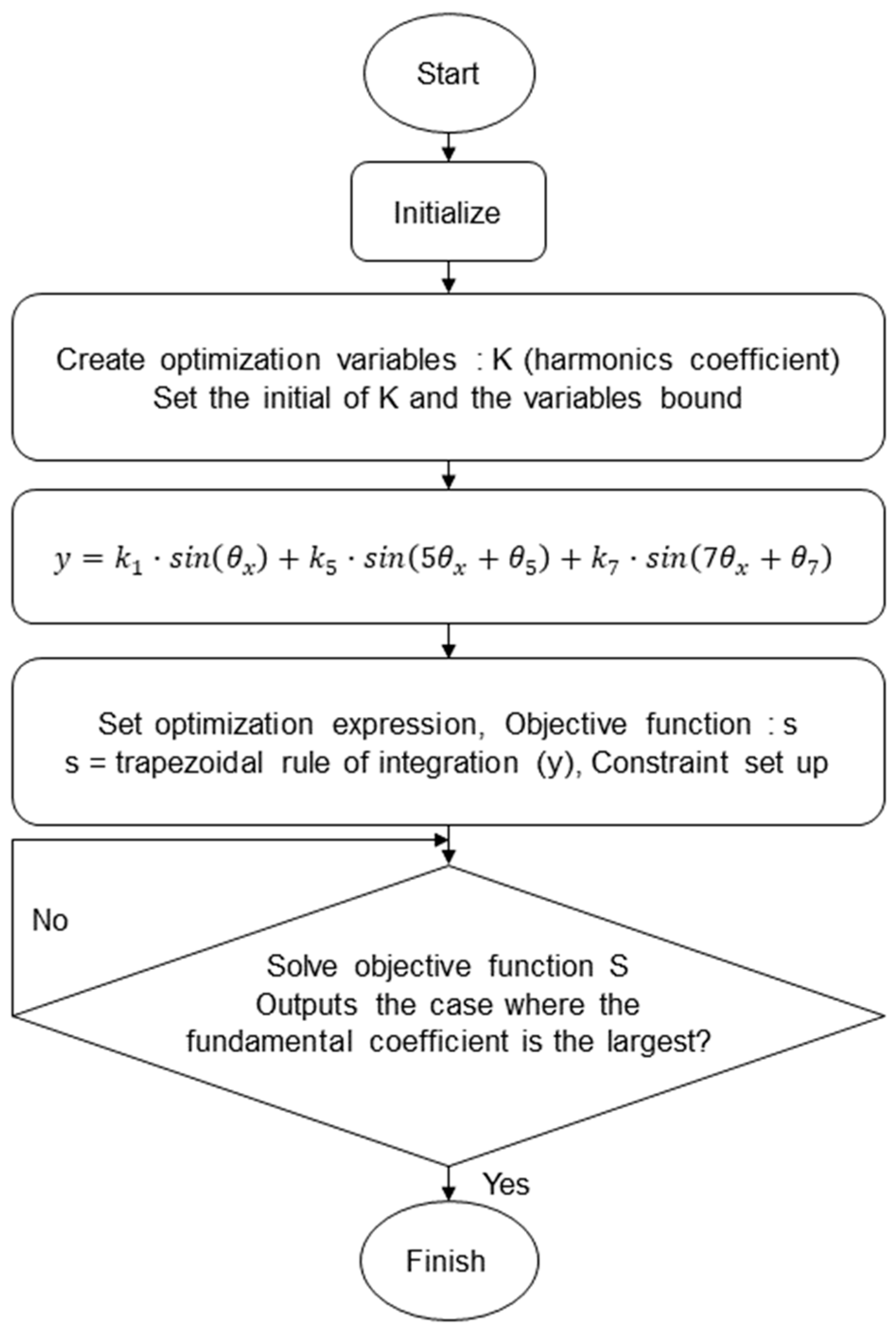
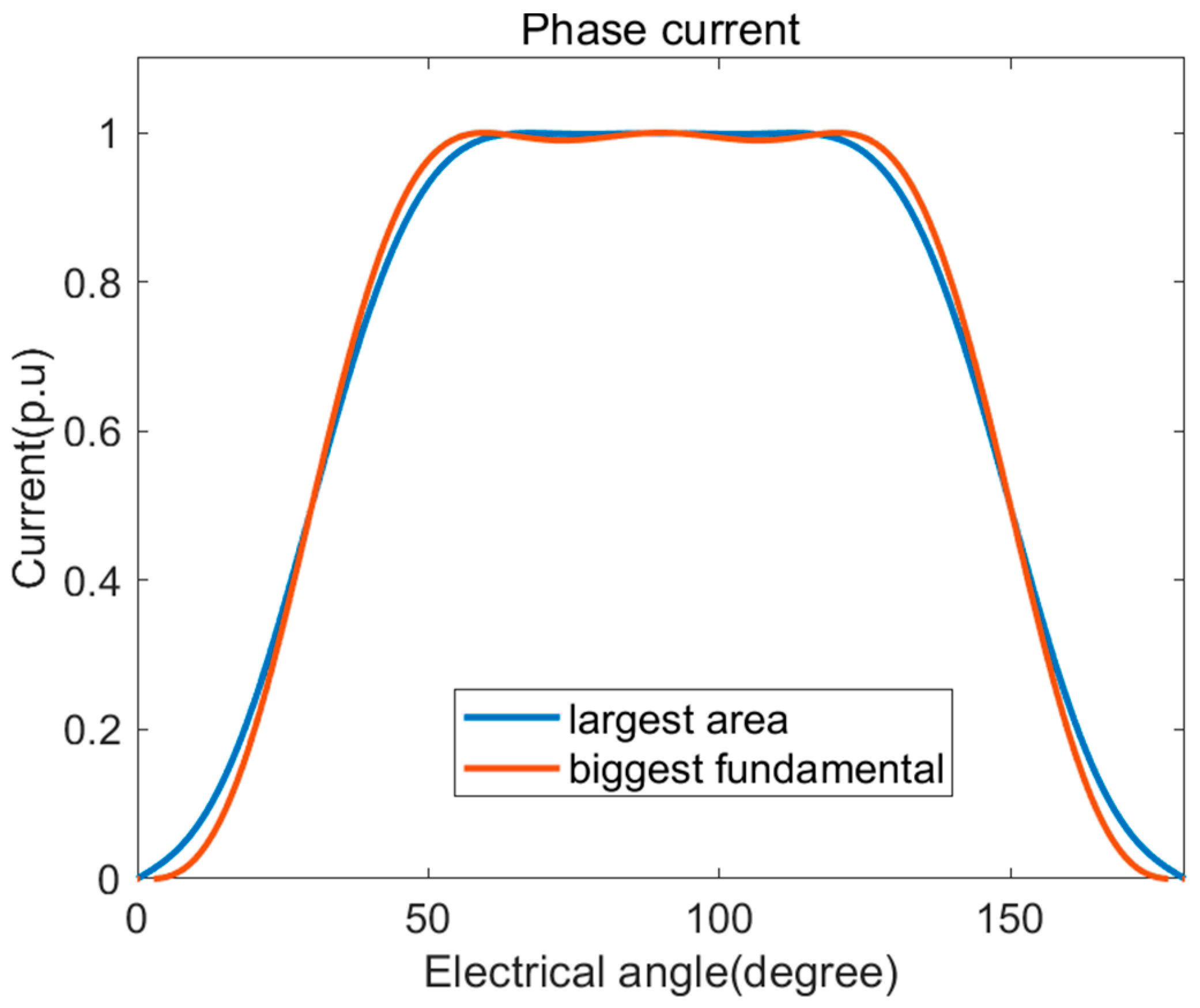
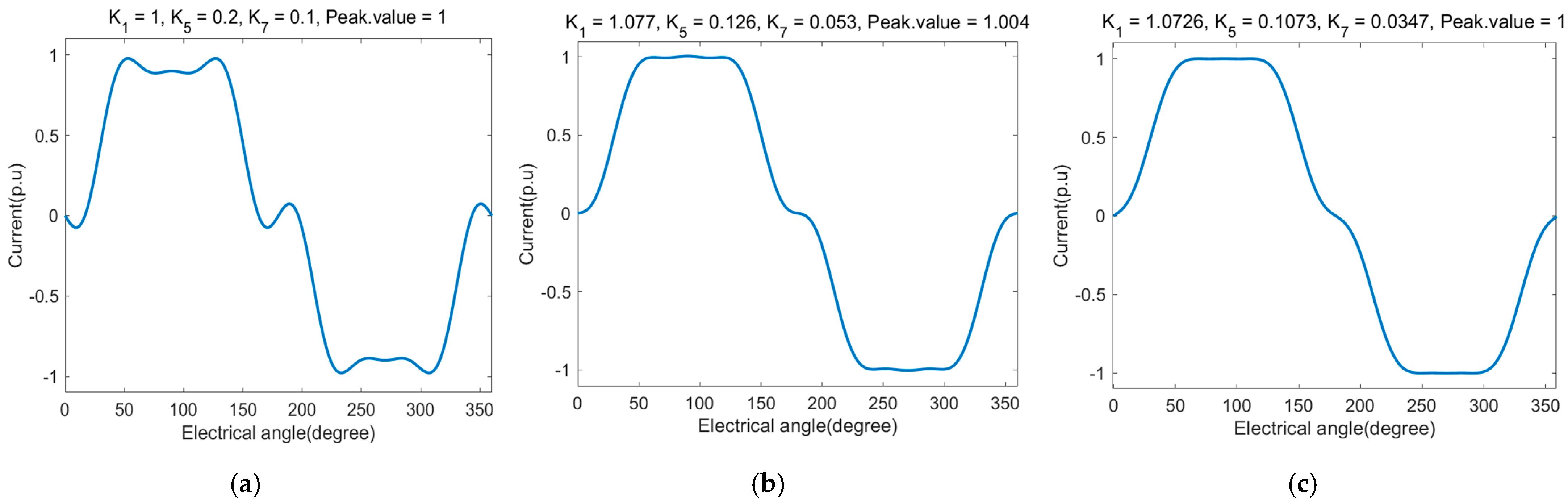
Each coefficient component was selected through the process shown in Figure 1 using the optimization module of MATLAB. The constraint conditions set in the process of Figure 1 were as follows: (1) The maximum current peak did not exceed 1 p.u., and (2) the area of 1/2 of the periodic current was maximized. Using the above optimization constraint settings, various forms of current can be generated. Figure 2 shows the current in two cases where the maximum current range is optimized under the conditions of 0.99 to 1 p.u. One shows the case where the fundamental coefficient is maximum, and the other shows the case where the area of current is the largest. Based on several optimization tests, when the maximum current (peak) range was set close to 1 p.u., it converged into a case with the largest area of current. We calculated the coefficient at which the current achieved the maximum area under the maximum current range conditions of 0.998 to 1 p.u. Figure 3a–c shows the currents that were visible during the optimization process. Figure 3a shows the current as the initial calculated value during the optimization process, Figure 3b shows the current as calculated when the maximum current range condition is set to 0.996 to 1.004 p.u, and Figure 3c shows the current as the result of the optimization process convergence. Table 1 presents the optimized harmonic coefficients determined according to the fifth + seventh-, fifth-, and seventh-harmonic injection methods and the fundamental control methods selected through this process. The fundamental control method controls only the fundamental components of the frame without harmonic injection.
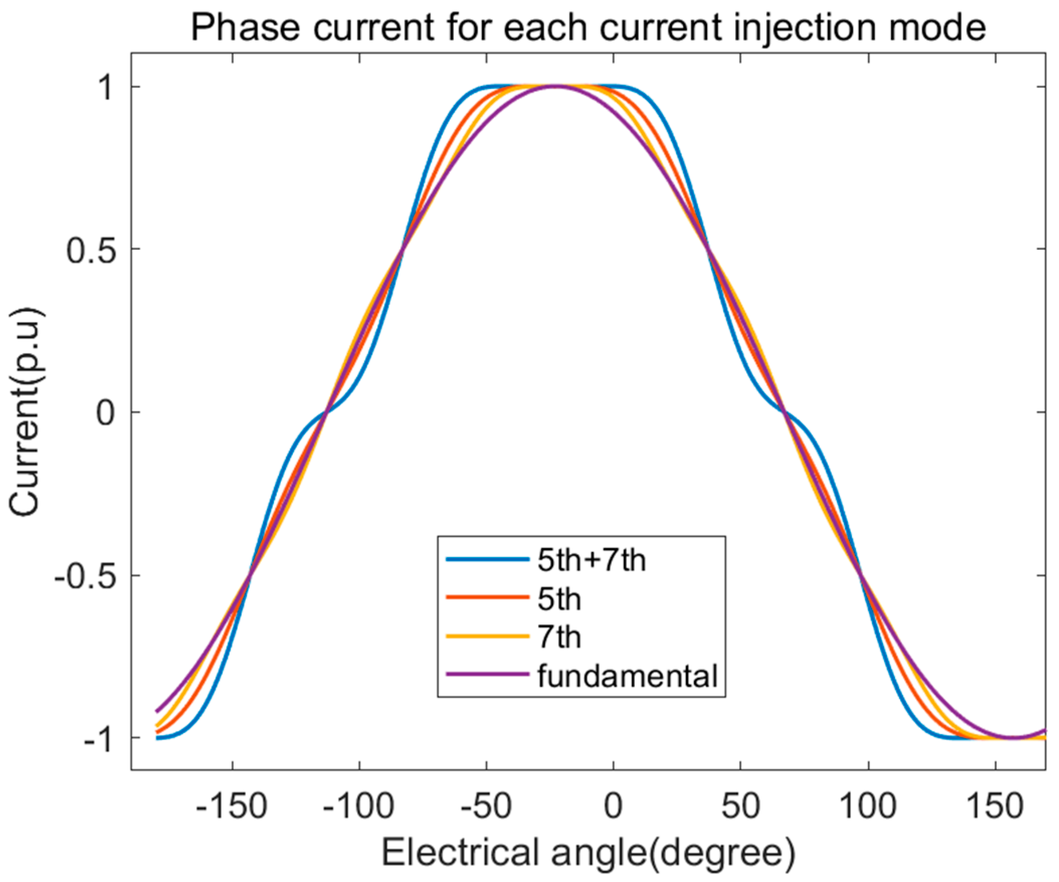
In Table 1, is 1.0726 p.u. for the fifth + seventh-harmonic injection method, 1.0462 p.u. for the fifth-harmonic injection method, and 1.0231 p.u. for the seventh-harmonic injection method. Additionally, based on 1 p.u., the fundamental growth rates are 7.26%, 4.62%, and 2.31%, respectively. Figure 4 shows the results of the optimized current for each harmonic injection method. It can be seen that the current area is large in the order of fifth + seventh-, fifth-, and seventh-harmonic injection methods under a maximum current of 1 p.u. or less. Therefore, when the current area increases within the maximum current limit by injecting harmonics, the fundamental component also increases. As shown in Section 2.1, increasing the fundamental component proportionally increases the output torque. Therefore, it is expected that the output torque will also increase in proportion to the current root mean square (RMS). In the next section, we analyze how much the output torque increases within the same current peak limit when the optimized harmonic coefficient is injected into the six-phase PMSM using an FEM simulation.
2.3. Analysis of Current Harmonic Methods Using FEM
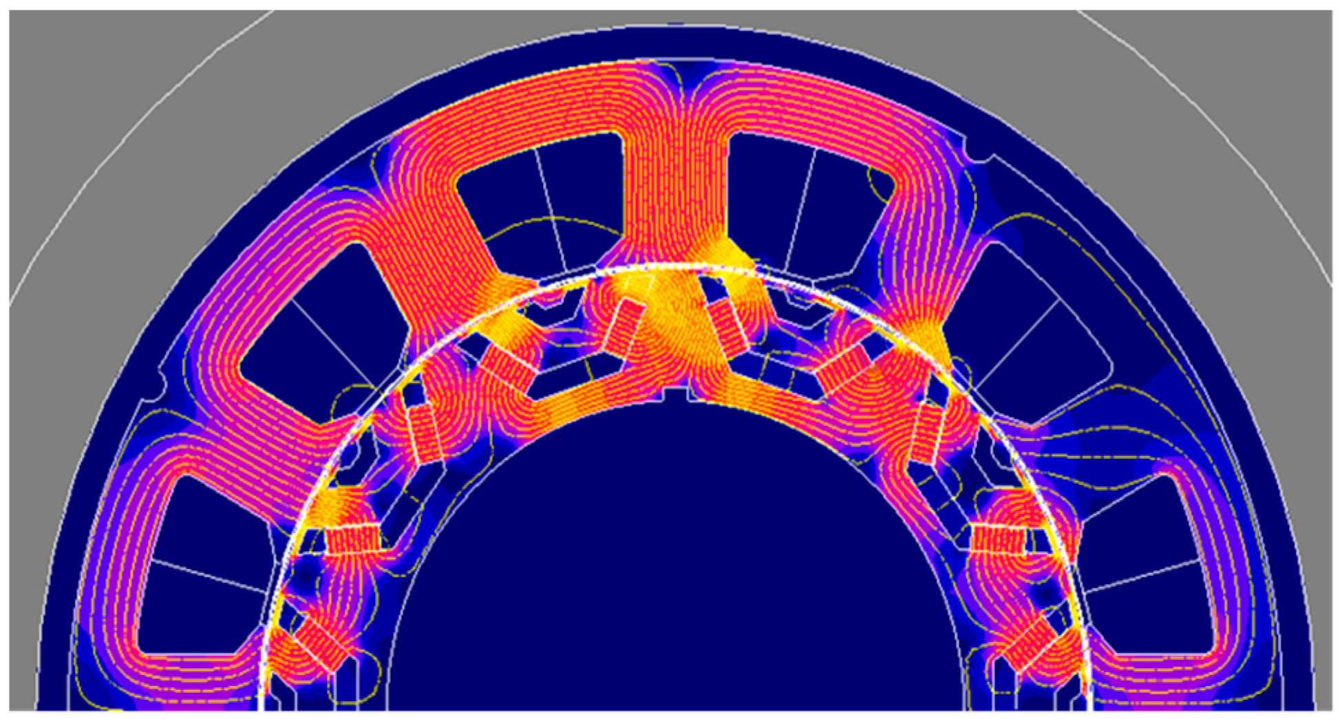
To compare the stator phase current and output torque performance of the six-phase PMSM under the various harmonic injection methods, we performed a FEM simulation using the Flux-2D software. To shorten the motor design time, a six-phase PMSM motor was designed using the Lumped parameter method (LPM), which can quickly calculate performance. The detailed design methods and specifications are presented in [16]. Figure 5 shows the FEM model of the test motor, and the design parameters are listed in Table 2. Figure 6 shows the distribution of magnetic flux density under 10 Arms, 5° (load angle), and fundamental operating conditions.
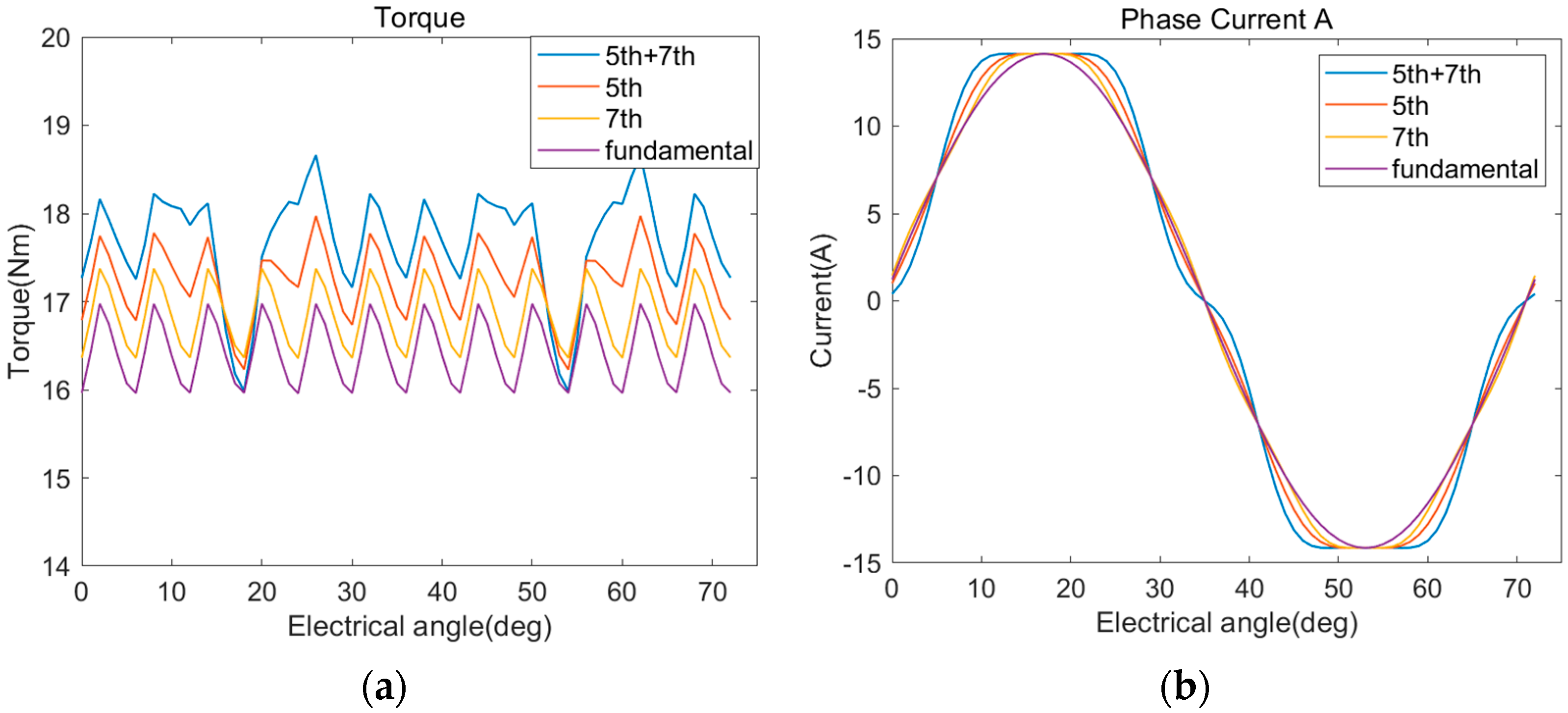
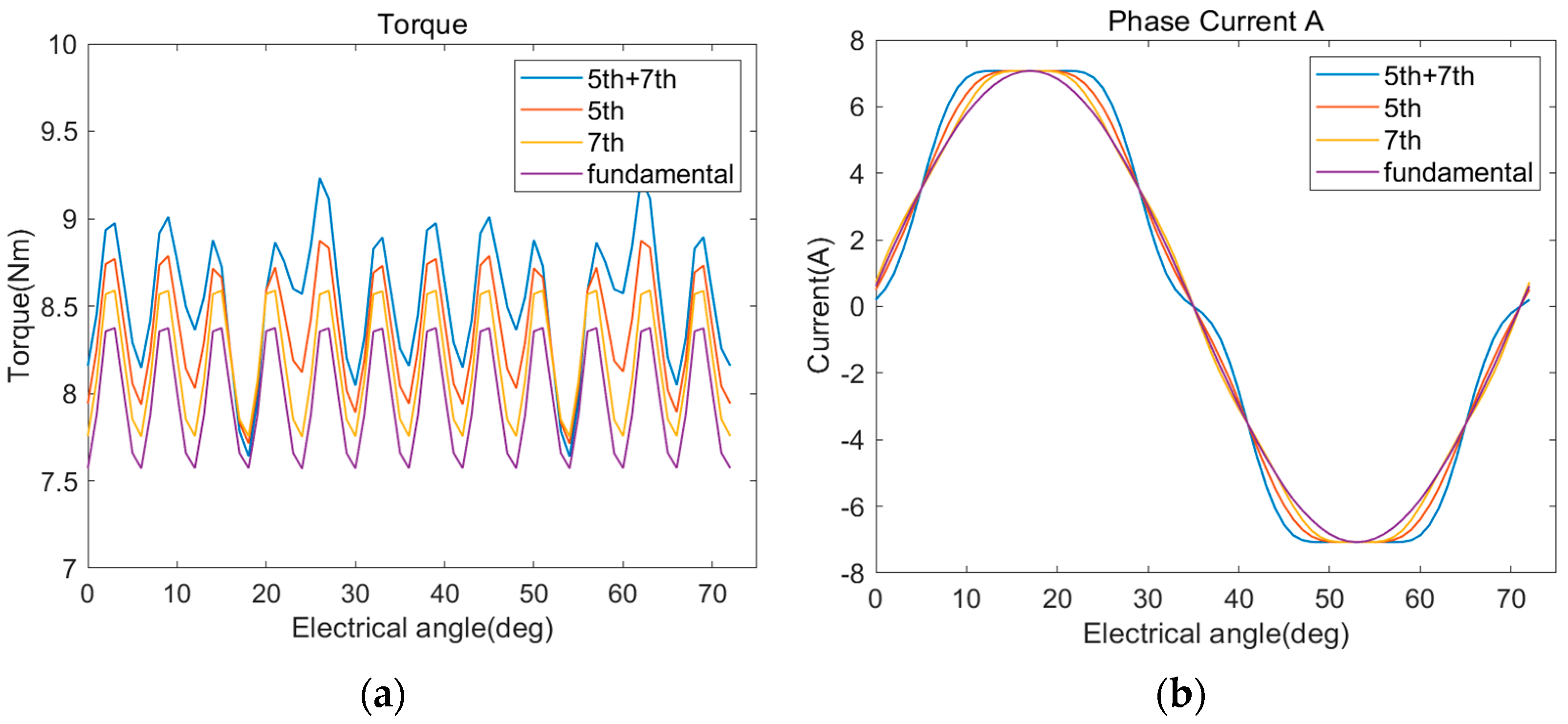
Figure 7 and Figure 8 show the FEM simulation results of the output torque and A-phase current of the test motor according to the harmonic injection methods under the same load angle of 5° and 480 r/min at 10 and 5 Arm currents, respectively. Table 3 shows FEM simulation results for phase stator current and output torque according to harmonic injection methods. The optimization coefficients calculated in Section 2 were used, and the peak values of the current were equally limited to 14.13 and 7.07, respectively. The current RMS values increased by 7%, 4.7%, and 2% based on the fundamental control method for the fifth + seventh-, fifth-, and seventh-harmonic injection methods, respectively. Increasing the fundamental component, i.e., fundamental coefficient, also proportionally increased the average torque. Therefore, the average torque for each injection method based on the fundamental control method increased by 7.5%, 5%, and 2.4%, respectively, under the 10 Arms condition and by 7.15%, 4.64%, and 2.5%, respectively, under the 5 Arms condition. Torque ripple yielded results of 15.16%, 9.88%, and 6.53% under the 10 Arms condition and 18.72%, 13.11%, and 10.17% under the 5 Arms condition.
Here, the harmonic coefficients , provide the harmonic ratio. The fifth + seventh-harmonic injection method harmonic proportion yielded results of 10.73% and 3.47% based on a fundamental magnitude of 1 p.u., and the fifth- and seventh-harmonic injection methods harmonic proportion yielded 4.72% and 2.36%, respectively. Therefore, increasing the harmonic injection coefficient increases the fundamental growth rates, effectively increasing the average output torque, as well as increasing the torque ripple as a trade-off. The fifth-harmonic injection method had a 2.5% lower output torque growth rate compared to the fifth + seventh-harmonic injection method but decreased torque ripple by 5.28%. The fifth-harmonic injection method increased the output torque by nearly 5% compared to the fundamental control method. Both the fifth and seventh-harmonic injection methods can be controlled via a PI controller by converting the injections into DC components using the Park transformation outlined in Equation (4). However, as the rotational speed of the motor increases, the control frequency must increase proportionally. The fifth-harmonic order is five times the fundamental frequency, and the seventh-harmonic order is seven times the fundamental frequency. For this reason, as the control frequency increases, the frequency of the seventh-harmonic components increases rapidly compared to the fifth-harmonic components, deviating from the current control bandwidth. Therefore, since the fifth-harmonic components are lower second order compared to the seventh-harmonic components, the current control band can be secured stably. The current RMS values increased by 4.7%, and 2% based on the fundamental control method for the fifth- and seventh-harmonic injection methods, respectively. The average torque for each injection method based on the fundamental control method increased by 5%, and 2.4%, respectively, under the 10 Arms condition. The fundamental growth rate of the fifth-harmonic injection method can then be doubled compared to that of the seventh-harmonic injection method; therefore, the average output torque growth rate can also be nearly doubled. For this reason, we selected the fifth-harmonic injection method for this study.
3. Control Scheme of Current Harmonic Injection
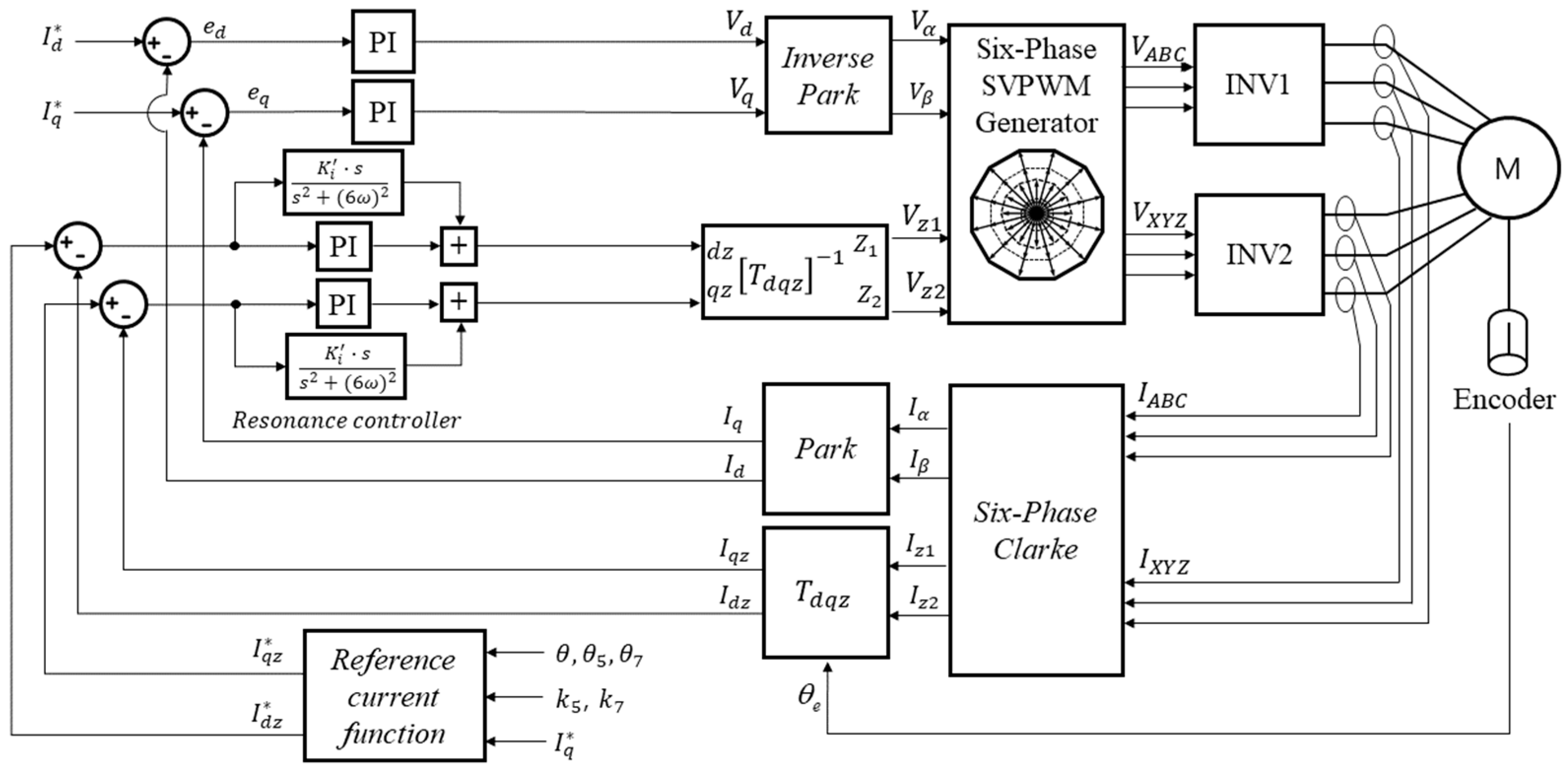
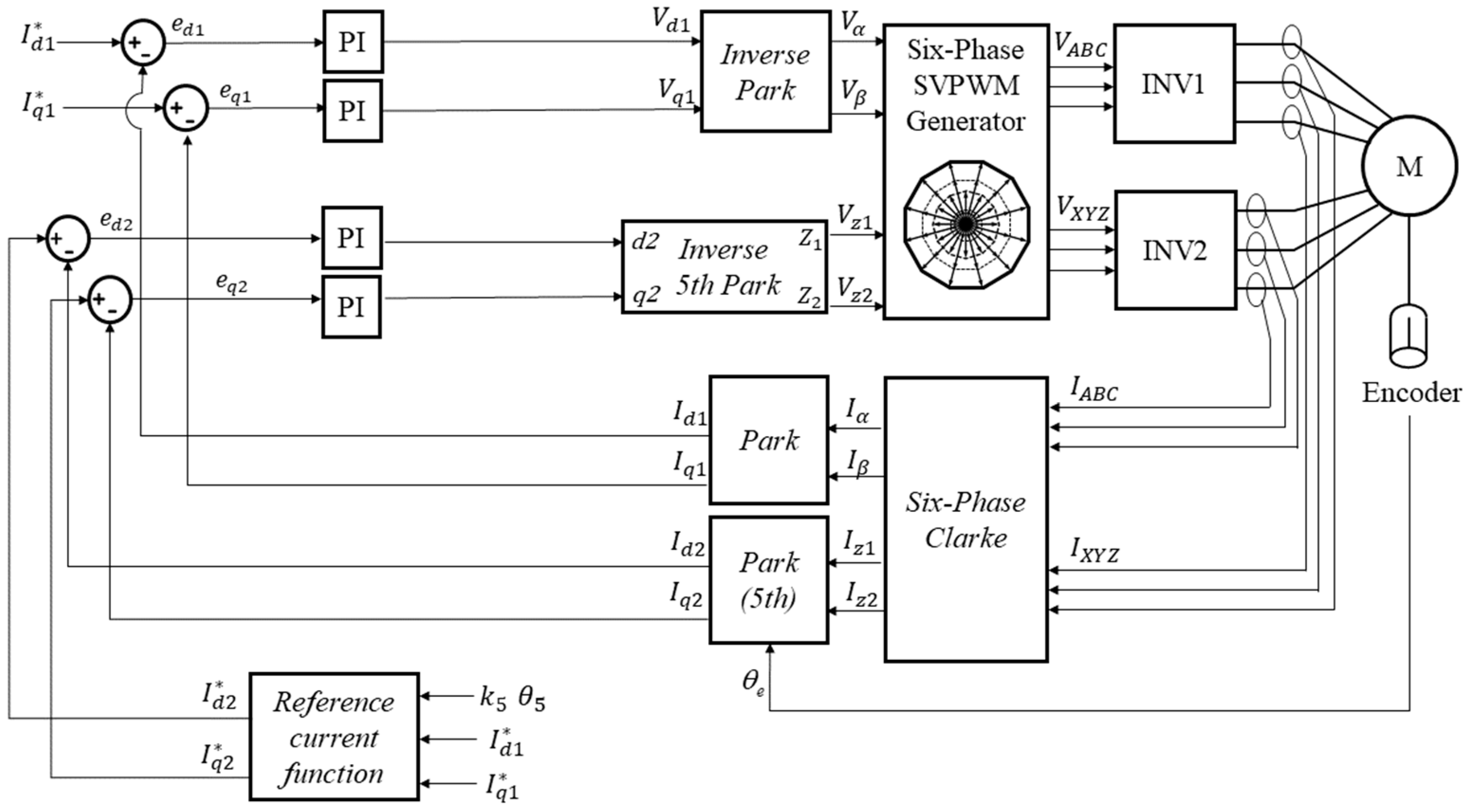
Before explaining the current control scheme for performing the fifth-harmonic injection method, we will briefly explain the fifth + seventh-harmonic injection method. The current control scheme based on VSD with fifth- and seventh-harmonic injection is shown in Figure 9. Details of the current-injection function and the fifth + seventh-harmonic injection method are presented in [8,14]. The reference phase current , components are calculated by current and load angle. The feedback phase currents , , which are measured current component, are converted into , , , currents through six-phase Clarke conversion. Then, fundamental current components are converted into , currents through Park transformation, and the harmonic current components are then converted into , currents through conversion. The six-phase Clarke conversion results in irregular currents in the fifth- and seventh-harmonic components in the planes. Then, we convert these harmonic components into a sixth-order sinusoidal form using the conversion outlined in Equations (12) and (13). This process is used to control the fifth- and seventh-harmonic components simultaneously by converting them into sixth sinusoidal forms.
The harmonic current-injection function for creating the fifth and seventh reference currents requires a separate conversion process to acquire the reference value of the sixth sine wave based on the fifth- and seventh-harmonic factors optimized in Section 2 [8,14]. To control the sine wave, a PI controller for DC component control and a resonance controller for AC component control are applied in parallel.
The current control method proposed in this paper does not control the sixth sinusoidal component obtained through conversion using a resonance controller, but converts the fifth-harmonic component into a DC component through Park transformation and controls it with a PI controller. The current control scheme based on VSD with fifth-harmonic injection is shown in Figure 10. The feedback phase currents , are converted into , currents through a six-phase Clarke conversion and Park transformation, but the , currents of the fifth-order components must be converted into , currents through fifth-order Park transformation. Next, the reference current function is considered the optimized fifth-harmonic coefficient , and optimized phase angle and , . These , components are calculated by current and load angle. In conclusion, reference currents are controlled using Equation (14):
The fifth-harmonic coefficient is a ratio value of the fifth harmonic to be injected based on the fundamental magnitude. Therefore, only the fifth-harmonic coefficient and phase angle to be injected into the fundamental reference need be considered. In addition, since it is difficult to predict harmonic current terms acting on a stator caused by the nonlinearity of an inverter or errors in the motor design process, the magnitude for each harmonic order and a phase-angle measurement process are experimentally required. In this way, the coefficient can be selected through an optimization process by experimentally measuring the magnitude and phase angle for each harmonic current order in the fundamental control method without modeling use of the parameters of a conventional six-phase motor.
If the reference to be injected can be determined, that reference is used in the current control loop. Reference and feedback currents are controlled through a PI controller, and these parameters are used to control an inverter via the SVPWM method after performing fifth-order inverse Park transformation. SVPWM is an inverter switching technique that has been used for a long period of time and is detailed in [15]. In summary, a resonance controller must be used to control the AC component in the fifth + seventh-harmonic injection method. However, the resonance controller mentioned in the introduction has the disadvantages of increased control instability and design complexity. Thus, we proposed a fifth-harmonic injection method that offers advantages in controller design and stability by controlling the harmonic component with a DC component through a PI controller without using a resonance controller. By applying this optimized coefficient and current control method, it is possible to find a condition in which the maximum average output torque can be obtained within the same current peak limit, which will be experimentally demonstrated in the next section.
4. Experimental Results for Fifth-Harmonic Current Injection
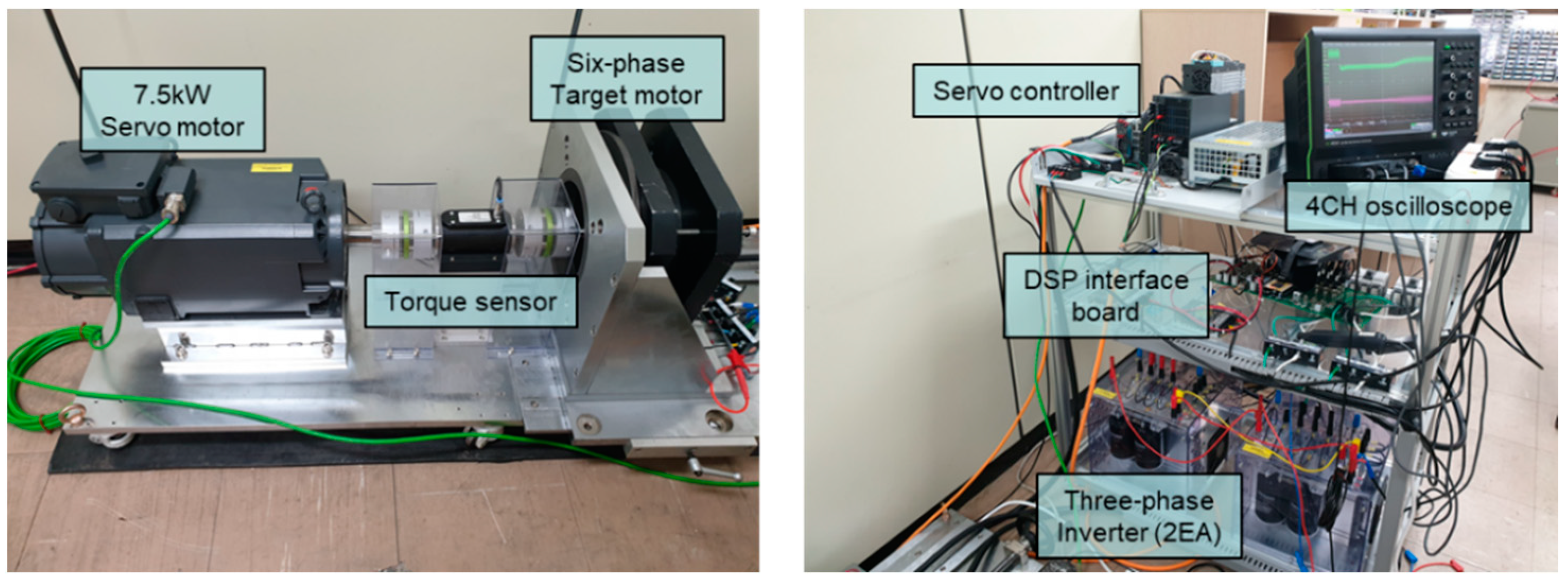
Figure 11 shows the six-phase PMSM used in the experiment to apply the fifth-harmonic injection method. The motor test system setup consisted of experimental instruments with a 7.5 kW servo motor, three-phase inverter (2EA), DC power supply, torque sensor, servo controller, and DSP interface board. Detailed model names of the experimental instruments are provided in Table 4. Figure 12 shows the overall experimental setup. The torque sensor used in this paper can measure the average torque 30 times per rotation of the rotor shaft. Therefore, since the measurable bandwidth was very low, it was not possible to experimentally provide information on torque ripple due to the fifth-harmonic injection. However, information on the average torque could be assessed, so the corresponding torque sensor was used. The test motor was driven using two Semikron AN-8005 three-phase inverters, and the switching frequency of the inverter was 10 kHz. The experiment was conducted as follows. First, the test speed was maintained using the speed control of the servo motor. When the load current and load angle were input into the motor, the motor began to function, and torque was generated by force rotating in the opposite direction.
4.1. Analysis of the Results of Applying Harmonic Coefficients
The coefficients optimized in Table 1 were considered to be ideal conditions, with only fundamental components and no harmonic disturbance component. Therefore, considering the magnitude and phase of the actual harmonic current order, the currents in the fundamental control method were measured for use in the fifth-harmonic optimization process. Additionally, each harmonic magnitude and phase were analyzed using FFT. The experiment was conducted at 480 r/min with load currents of 5 and 10 Arms and a load angle of 5°.
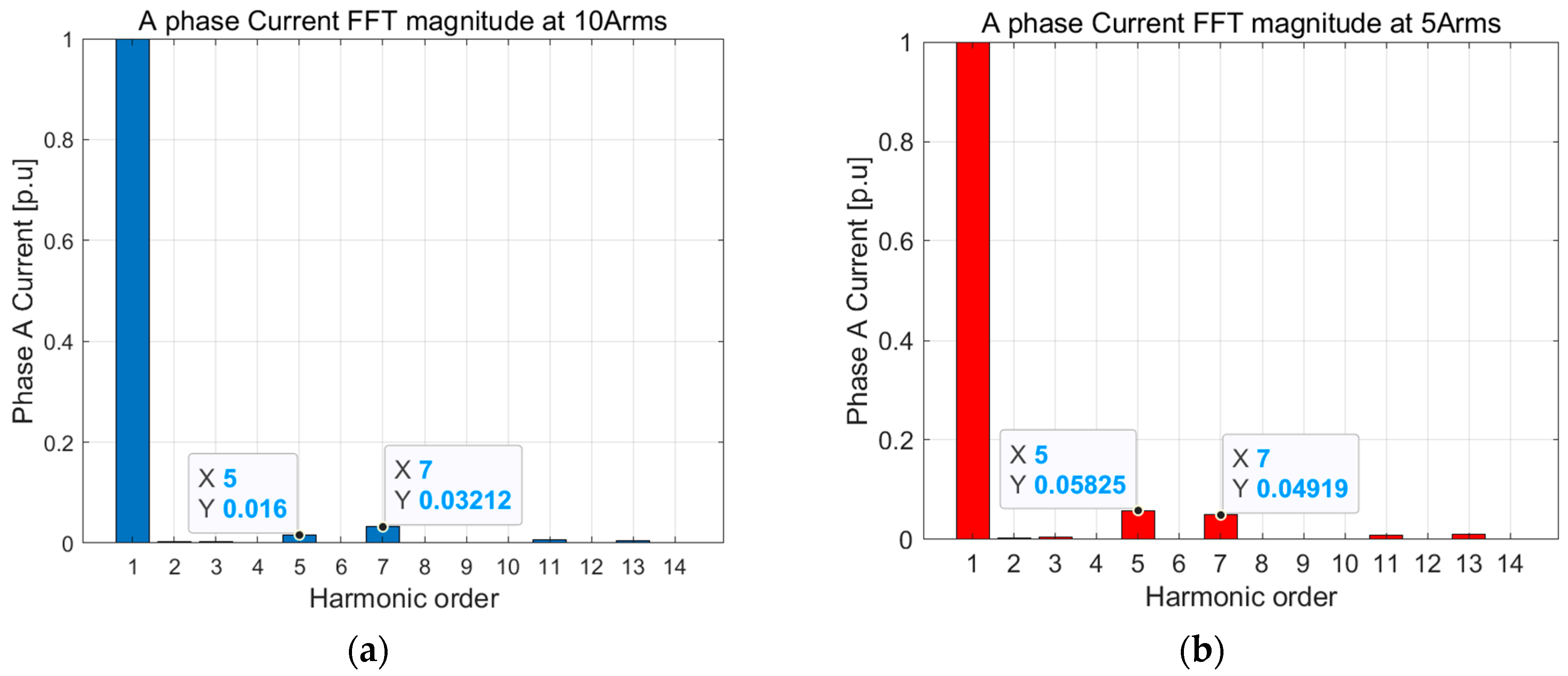
Figure 13 shows the results of measuring the A-phase current and average output torque of the fundamental control method under current conditions of 10 Arms. The phase current peak value is 14.35 A, the phase current RMS is 10 Arms, and the average output torque is 15.82 Nm. Figure 14a provides a graph showing the current measured in Figure 13 after normalizing the magnitude for each harmonic order through FFT analysis. The magnitude of the fifth- and seventh-harmonic coefficients was determined to be 1.6% and 3.21%, respectively, based on the fundamental magnitude, with a phase difference of about −35° and −54° in the fundamental phases.
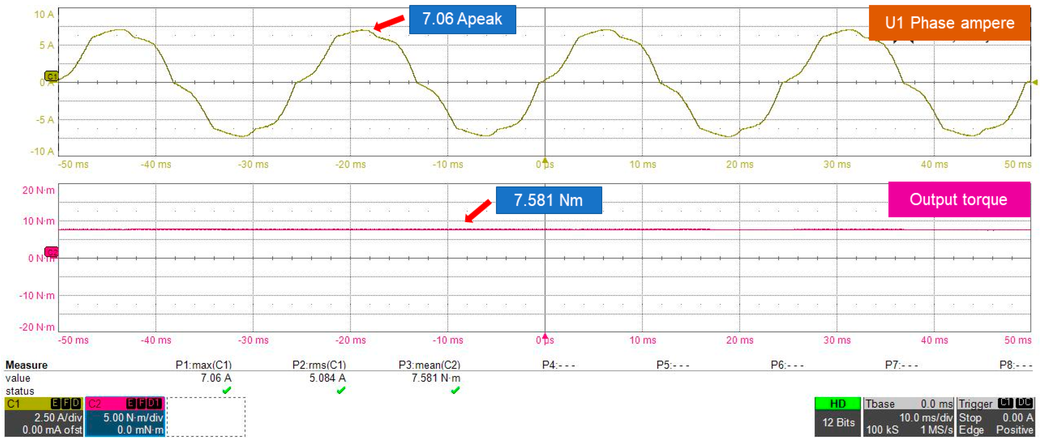
Figure 15 shows the result of measuring the A-phase current and average output torque of the fundamental control method under current conditions of 5 Arms. The phase current peak value is 7.06 A, the phase current RMS is 5.08 Arms, and the average output torque is 7.58 Nm. Figure 14b provides a graph showing the current measured in Figure 15 after normalizing the magnitude for each harmonic order through FFT analysis. The magnitude of the fifth- and seventh-harmonic coefficients was determined to be 5.8% and 4.91%, respectively, based on the fundamental magnitude, with a phase difference of about −73° and −45° in the fundamental phases.
Apart from the fifth and seventh harmonics, the harmonic orders did not have a significant impact on the current because the magnitude was very small. Therefore, only the fifth- and seventh-harmonic components were considered to derive the harmonic coefficient through the optimization process.
Table 5 presents the fundamental coefficient and fifth-harmonic coefficient selected through the optimization process based on the magnitude and phase of the fifth and seventh harmonics measured by the fundamental control method under 10 and 5 Arms conditions. Here, at 10 Arms, is 1.04, and is 0.074. At 5 Arms, is 1.026, is 0.0876, and the fundamental growth rates are 4% and 2.6%, respectively. As shown in Table 1, the fundamental growth rate is 4.62% under 10 Arms ideal conditions, and the fundamental growth rate is 4% under 10 Arms experimental conditions. Under the rated conditions in which the fifth- and seventh-harmonic components are relatively small, the difference in growth rate is only 0.62%. However, under the 5 Arms condition, where the fifth- and seventh-harmonic magnitudes are higher than the rated current condition, the fundamental growth rate was observed to be 2.6%. Under the 5 Arms condition, the fundamental growth rate is 1.4% lower than the rated current of 10 Arms.
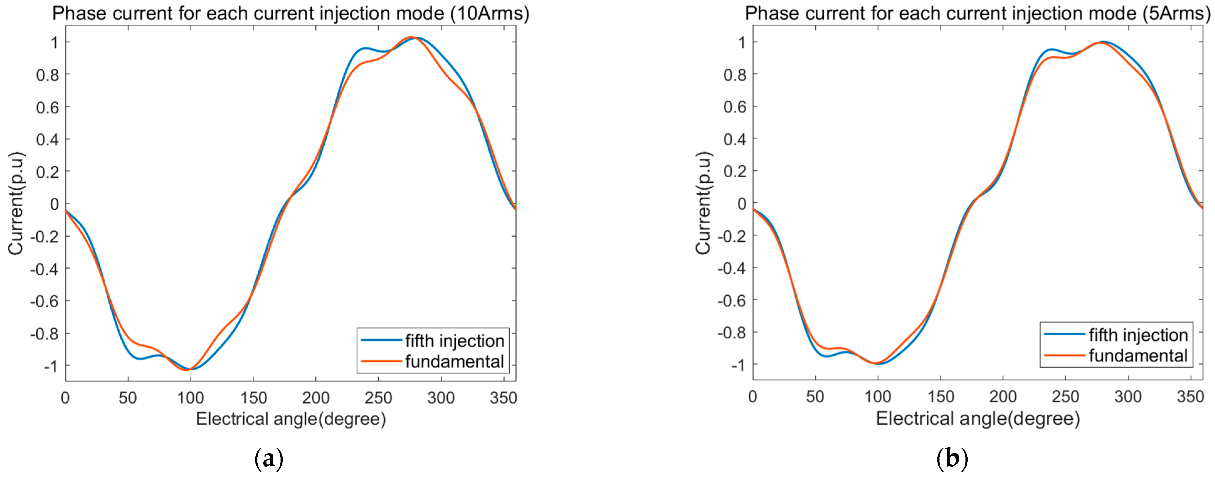
Figure 16 shows a comparison between the A-phase current waveform in the measured fundamental control method and the current waveform calculated by applying the fundamental and fifth-harmonic coefficients optimized based on the relevant components. Figure 14a,b, respectively, show the results of the comparison between 10 and 5 Arms conditions. Here, the same peak-value reference current area widened after the optimized coefficient was applied. Therefore, it can be seen that both of the constraints on the coefficient optimization process mentioned in Section 2.2 are satisfied. In the next section, the fifth-harmonic injection method is applied based on the coefficients optimized using the harmonic magnitude and phase obtained through experiments.
4.2. Results of Applying the Optimized Harmonic Coefficient
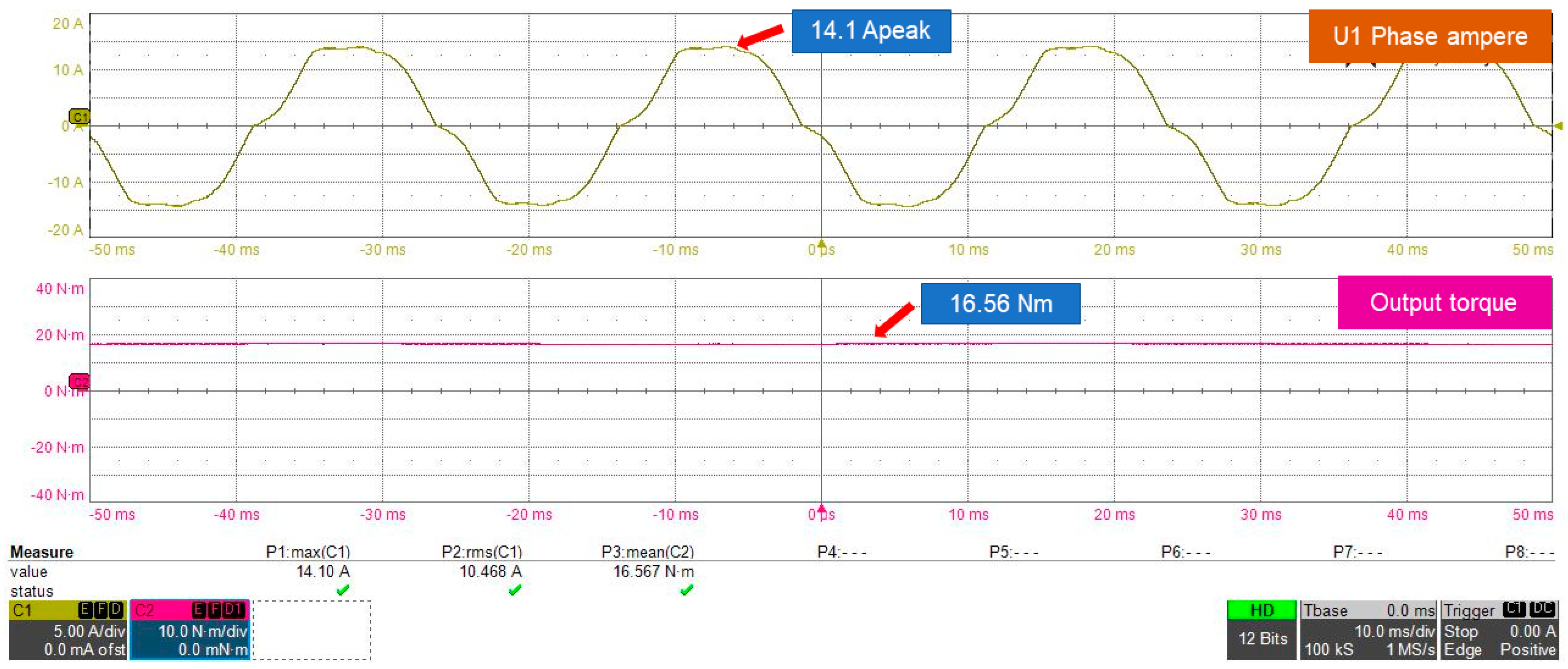
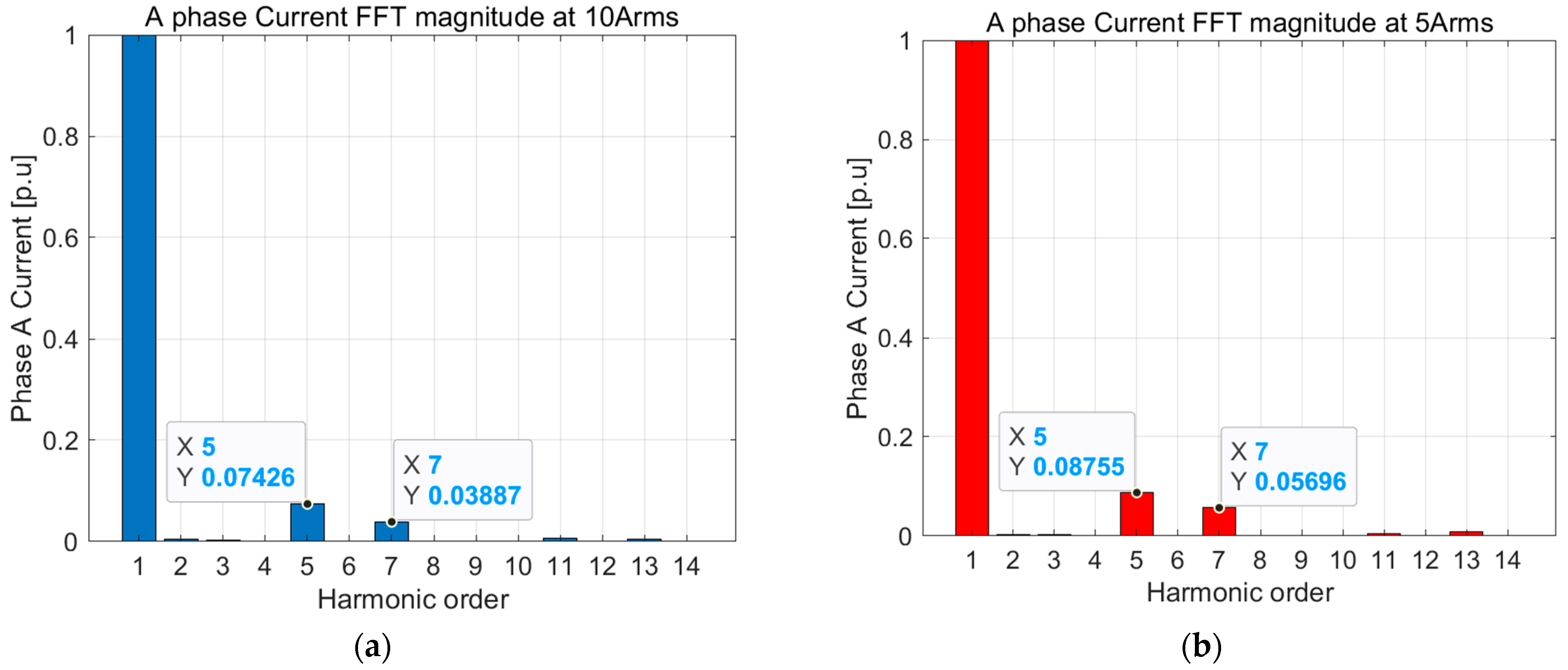
Figure 17 shows the results of measuring the A-phase current and average output torque waveform in the fifth-harmonic injection method under 10 Arms. The phase current peak value is 14.10 A, the phase current RMS is 10.46 Arms, and the average output torque is 16.57 Nm. Compared to the fundamental control method shown in Figure 13, the current peak of the fifth-harmonic injection method is 1.41% lower, the phase current RMS is increased by about 4.6%, and the average output torque is increased by about 4.6%. We confirmed that the average output torque could be increased by nearly 5% within the same current peak limit under the rated 10 Arms current conditions. Moreover, the output torque increase rate under the FEM simulation is similar (Table 3). Figure 18a illustrates a graph showing the current measured in Figure 17 after normalizing the magnitude of each harmonic order through FFT analysis. The magnitude values of the fifth- and seventh-harmonic coefficients were determined to be 7.4% and 3.8% based on the fundamental magnitude. In this way, we identified the fifth-harmonic injection of 7.4% optimized in Table 5.
Figure 19 shows the results of measuring the A-phase current and average output torque waveform via the fifth-harmonic injection method under current conditions of 5 Arms. Here, the phase current peak value is 7.05 A, the phase current RMS is 5.227 Arms, and the average output torque is 7.79 Nm. The current peak of the fifth-harmonic injection method here is almost the same as that of the fundamental control method shown in Figure 15. Additionally, the phase current RMS increased by 2.81%, and the average output torque increased by 2.77%. Therefore, under 5 Arms conditions, the fundamental growth rate in Table 5 is similar within 2.6% of the same current peak limit. Figure 18b provides a graph showing the current measured in Figure 19 after normalizing the magnitude for each harmonic order through FFT analysis. The magnitude values of the fifth- and seventh-harmonic coefficients were determined to be 8.7% and 5.6% based on the fundamental magnitude. In this way, we identified the fifth-harmonic injection of 8.7% optimized in Table 5. Therefore, the fifth-harmonic injection method presented in this paper can be used to inject the fifth harmonic at the desired ratio based on fundamental magnitude. In addition, based on harmonic magnitude and phase information acquired via FFT analysis, the output torque can be increased within the same current peak via the fifth-harmonic injection method.
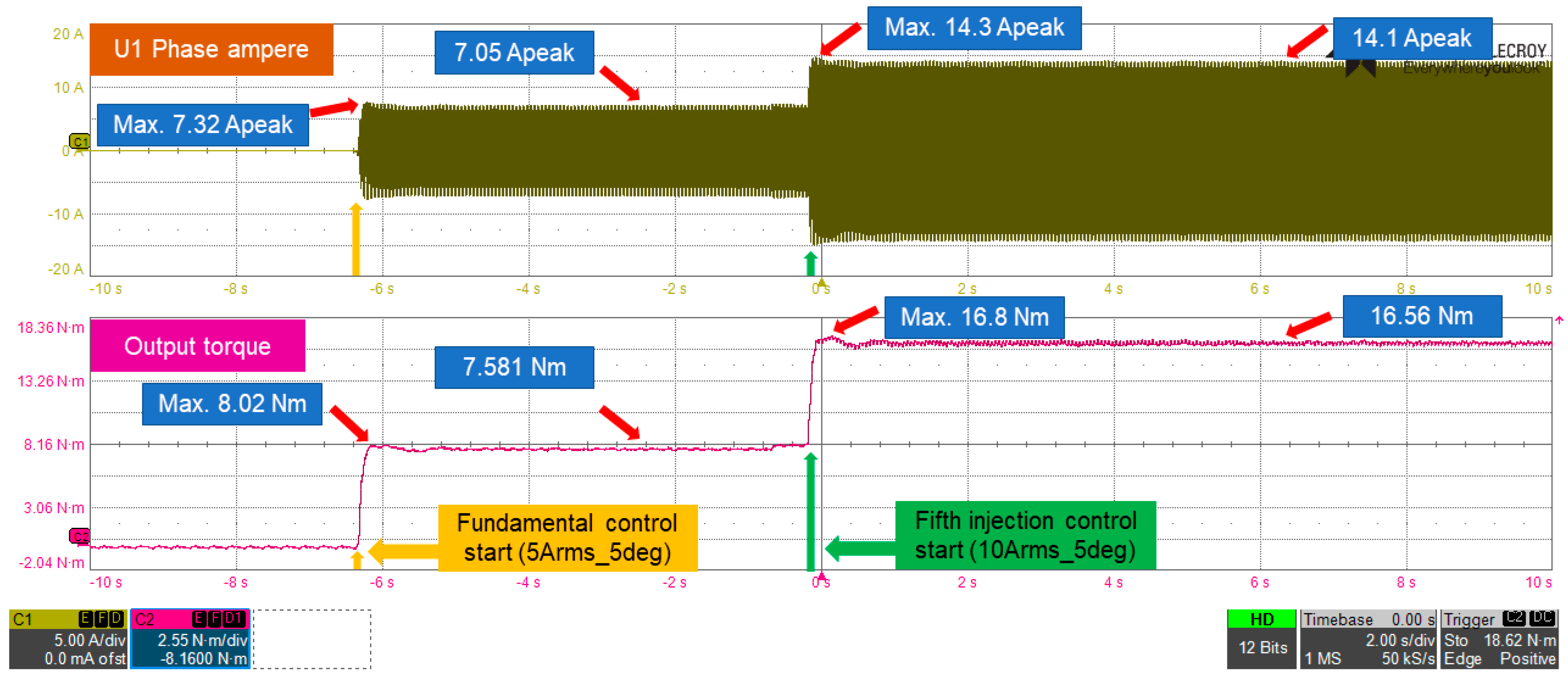
The experiment was conducted at 480 r/min with 5° load angle to check the transient state of the phase current and output torque according to control method conversion. The results for the experiment are shown in Figure 20. The motor was started in the fundamental control method under 5 Arms conditions with no load. When the control method conversion begins, the current peak and output torque are increased by 7.32 A and 8.02 Nm, respectively, and then they gradually decrease, so the current peak and output torque are maintained in a stable state at 7.05 A and 7.58 Nm, respectively. When the fundamental control method under 5 Arms conditions is converted into the fifth-harmonic injection control method under 10 Arms conditions, the current peak and output torque are increased by 14.3 A and 16.8 Nm, respectively. Like the transient state of the fundamental control method, the current peak and output torque decreased gradually, so they remained stable at 14.1 A and 16.56 Nm, respectively. The fundamental and fifth control execution time from the moment the command is received is within 20 ms. Therefore, we confirmed that the transient state of each method switching shows a similar trend and is stably controlled. Table 6 shows the system efficiency for each method. Here, input power is the power of the DC link, and output power is the inverter output power. The input power required in the fifth-harmonic injection method increased compared to the fundamental control method. This is because when the fifth-harmonic injection method is used, the current RMS can be increased to equalize the phase current peak value at the fundamental control method. When comparing efficiency under the same RMS current condition, the fundamental control method increased by 0.29%, compared to the fifth-harmonic injection control method, and the efficiency increased by 0.34%, under 10 Arms conditions. As a result, it can be seen that if the fifth-harmonic current is injected, the efficiency does not decrease but slightly increases.
5. Conclusions
In this paper, we proposed a method to improve the output torque of a six-phase PMSM within the same current peak limit using a fifth-harmonic injection for each phase current of the stator. Existing methods to improve output torque through fifth + seventh-harmonic injection use a resonance controller to control the harmonic component. However, due to the narrow control bandwidth, there are disadvantages to this method, such as controller instability and design complexity in the discretization process. To solve these issues, we converted the fifth-harmonic component into a DC component and controlled it via a PI controller due to the limitations of control freedom in VSD theory and to ensure a stable current control bandwidth. The fifth-harmonic reference used to perform the fifth-harmonic injection considered the stator current harmonics caused by the nonlinearity of the inverter and errors in the motor design process. In addition, the results obtained through FFT analysis of the harmonic components were used in the required fifth-harmonic optimization process.
The experiment and FEM simulation were conducted based on a previously designed six-phase PMSM model. In the FEM simulation, under a rated current of 10 Arms for the motor, the fifth-harmonic injection method provided an output torque increase rate about 2.5% lower than that of the fifth + seventh-harmonic injection method. However, we confirmed that the output torque could be increased by nearly 5% compared to that under the fundamental control method. Moreover, we confirmed through FFT analysis that the ratio of fifth harmonics to be controlled was correctly injected through fifth-harmonic injection experiments under 10 and 5 Arms conditions. In addition, the increase rate of output torque was about 1.8 times higher under the rated current condition of 10 Arms in which the harmonic component was relatively small compared to that under the 5 Arms condition.
Ultimately, using the fifth-harmonic injection method presented in this paper, output torque can be proportionally improved by increasing the fundamental ratio within the same current peak via the measured current information analyzed by FFT without requiring torque modeling using the physical properties of the motor.
Author Contributions
Design and application—D.H.; Literature review, manuscript preparation and simulations—D.H. and D.Y.; Experimental verification—D.H., N.K. and J.B.; Final review of manuscript, corrections—N.K. and J.B. All authors have read and agreed to the published version of the manuscript.
Funding
This research was funded by grant(2018R1D1A3B0704376413) from National Research Foundation of Korea (NRF) and supported by Education and Research promotion program of KOREATECH in 2022.
Institutional Review Board Statement
Not applicable.
Informed Consent Statement
Not applicable.
Data Availability Statement
Not applicable.
Conflicts of Interest
The authors declare no conflict of interest.
References
- Guan, Y.; Zhu, Z.Q.; Afinowi, I.A.A.; Mipo, J.C.; Farah, P. Comparison between induction machine and interior permanent magnet machine for electric vehicle application. In Proceedings of the 2014 17th International Conference on Electrical Machines and Systems (ICEMS), Hangzhou, China, 22–25 October 2014; pp. 144–150. [Google Scholar] [CrossRef]
- Cao, R.; Mi, C.; Cheng, M. Quantitative Comparison of Flux-Switching Permanent-Magnet Motors with Interior Permanent Magnet Motor for EV, HEV, and PHEV Applications. IEEE Trans. Magn. 2012, 48, 2374–2384. [Google Scholar] [CrossRef]
- Miyajima, T.; Fujimoto, H.; Fujitsuna, M. A Precise Model-Based Design of Voltage Phase Controller for IPMSM. IEEE Trans. Power Electron. 2013, 28, 5655–5664. [Google Scholar] [CrossRef]
- Kallio, S.; Karttunen, J.; Peltoniemi, P.; Silventoinen, P.; Pyrhonen, O. Online Estimation of Double-Star IPM Machine Parameters Using RLS Algorithm. IEEE Trans. Ind. Electron. 2014, 61, 4519–4530. [Google Scholar] [CrossRef]
- Levi, E. Multiphase Electric Machines for Variable-Speed Applications. IEEE Trans. Ind. Electron. 2008, 55, 1893–1909. [Google Scholar] [CrossRef]
- Levi, E.; Barrero, F.; Duran, M.J. Multiphase machines and drives—Revisited. IEEE Trans. Ind. Electron. 2016, 63, 429–432. [Google Scholar] [CrossRef] [Green Version]
- Bojoi, R.; Farina, F.; Tenconi, A.; Profumi, F.; Levi, E. Dual three-phase induction motor drive with digital current control in the stationary reference frame. Power Eng. 2006, 20, 40–43. [Google Scholar] [CrossRef]
- Feng, G.; Lai, C.; Kelly, M.; Kar, N.C. Dual Three-Phase PMSM Torque Modeling and Maximum Torque per Peak Current Control through Optimized Harmonic Current Injection. IEEE Trans. Ind. Electron. 2019, 66, 3356–3368. [Google Scholar] [CrossRef]
- Che, H.S.; Levi, E.; Jones, M.; Hew, W.-P.; Rahim, N.A. Current Control Methods for an Asymmetrical Six-Phase Induction Motor Drive. IEEE Trans. Power Electron. 2014, 29, 407–417. [Google Scholar] [CrossRef] [Green Version]
- Karttunen, J.; Kallio, S.; Peltoniemi, P.; Silventoinen, P.; Pyrhonen, O. Decoupled Vector Control Scheme for Dual Three-Phase Permanent Magnet Synchronous Machines. IEEE Trans. Ind. Electron. 2014, 61, 2185–2196. [Google Scholar] [CrossRef]
- Barrero, F.; Duran, M.J. Recent Advances in the Design, Modeling, and Control of Multiphase Machines—Part I. IEEE Trans. Ind. Electron. 2016, 63, 449–458. [Google Scholar] [CrossRef]
- Duran, M.J.; Barrero, F. Recent Advances in the Design, Modeling, and Control of Multiphase Machines—Part II. IEEE Trans. Ind. Electron. 2016, 63, 459–468. [Google Scholar] [CrossRef]
- Ryu, H.-M.; Kim, J.-H.; Sul, S.-K. Analysis of multiphase space vector pulse-width modulation based on multiple d-q spaces concept. IEEE Trans. Power Electron. 2005, 20, 1364–1371. [Google Scholar] [CrossRef]
- Hu, Y.; Zhu, Z.Q.; Odavic, M. Torque Capability Enhancement of Dual Three-Phase PMSM Drive with Fifth and Seventh Current Harmonics Injection. IEEE Trans. Ind. Appl. 2017, 53, 4526–4535. [Google Scholar] [CrossRef]
- Zhao, Y.; Lipo, T. Space vector PWM control of dual three-phase induction machine using vector space decomposition. IEEE Trans. Ind. Appl. 1995, 31, 1100–1109. [Google Scholar] [CrossRef]
- Hyun, D.; Yun, D.; Baek, J. Optimal Design of a Six-Phase Permanent-Magnet-Assisted Synchronous Reluctance Motor to Convert into Three Phases for Fault-Tolerant Improvement in a Traction System. Appl. Sci. 2021, 11, 8508. [Google Scholar] [CrossRef]
- Wang, K.; Zhang, J.Y.; Gu, Z.Y.; Sun, H.Y.; Zhu, Z.Q. Torque Improvement of Dual Three-Phase Permanent Magnet Machine Using Zero Sequence Components. IEEE Trans. Magn. 2017, 53, 8109004. [Google Scholar] [CrossRef]
- Lyra, R.; Lipo, T. Torque density improvement in a six-phase induction motor with third harmonic current injection. IEEE Trans. Ind. Appl. 2002, 38, 1351–1360. [Google Scholar] [CrossRef]
- Stumberger, B.; Stumberger, G.; Hamler, A.; Trlep, M.; Jesenik, M.; Gorican, V. Increasing of output power capability in a six-phase flux-weakened permanent magnet synchronous motor with a third harmonic current injection. IEEE Trans. Magn. 2003, 39, 3343–3345. [Google Scholar] [CrossRef]
- Huang, J.; Zheng, P.; Sui, Y.; Zheng, J.; Yin, Z.; Cheng, L. Third Harmonic Current Injection in Different Operating Stages of Five-Phase PMSM with Hybrid Single/Double Layer Fractional-Slot Concentrated Winding. IEEE Access 2021, 9, 15670–15685. [Google Scholar] [CrossRef]
- Gu, Z.Y.; Wang, K.; Zhu, Z.Q.; Wu, Z.Z.; Liu, C.; Cao, R.W. Torque Improvement in Five-Phase Unequal Tooth SPM Machine by Injecting Third Harmonic Current. IEEE Trans. Veh. Technol. 2018, 67, 206–215. [Google Scholar] [CrossRef]
- Cervone, A.; Slunjski, M.; Levi, E.; Brando, G. Optimal Third-Harmonic Current Injection for Asymmetrical Multiphase Permanent Magnet Synchronous Machines. IEEE Trans. Ind. Electron. 2021, 68, 2772–2783. [Google Scholar] [CrossRef] [Green Version]
- Farshadnia, M.; Cheema, M.A.M.; Dutta, R.; Fletcher, J.; Rahman, M.F. Detailed Analytical Modeling of Fractional-Slot Concentrated-Wound Interior Permanent Magnet Machines for Prediction of Torque Ripple. IEEE Trans. Ind. Appl. 2017, 53, 5272–5283. [Google Scholar] [CrossRef]
- Dhulipati, H.; Mukundan, S.; Lai, C.; Mukherjee, K.; Tjong, J.; Kar, N.C. Multiple Reference Frame-Based Extended Concentrated Wound PMSM Model Considering PM Flux Linkage and Inductance Harmonics. IEEE Trans. Energy Convers. 2019, 34, 731–740. [Google Scholar] [CrossRef]
- Kim, H.; Han, Y.; Lee, K.; Bhattacharya, S. A Sinusoidal Current Control Strategy Based on Harmonic Voltage Injection for Harmonic Loss Reduction of PMSMs With Non-Sinusoidal Back-EMF. IEEE Trans. Ind. Appl. 2020, 56, 7032–7043. [Google Scholar] [CrossRef]
- Khajehoddin, S.A.; Karimi-Ghartemani, M.; Jain, P.K.; Bakhshai, A. A Resonant Controller with High Structural Robustness for Fixed-Point Digital Implementations. IEEE Trans. Power Electron. 2012, 27, 3352–3362. [Google Scholar] [CrossRef]
- Yepes, A.G.; Freijedo, F.D.; Doval-Gandoy, J.; López, Ó.; Malvar, J.; Fernandez-Comesaña, P. Effects of Discretization Methods on the Performance of Resonant Controllers. IEEE Trans. Power Electron. 2010, 25, 1692–1712. [Google Scholar] [CrossRef]
- Zhou, C.; Yang, G.; Su, J. PWM Strategy With Minimum Harmonic Distortion for Dual Three-Phase Permanent-Magnet Synchronous Motor Drives Operating in the Overmodulation Region. IEEE Trans. Power Electron. 2016, 31, 1367–1380. [Google Scholar] [CrossRef]
- Wang, X.; Wang, Z.; Xu, Z. A Hybrid Direct Torque Control Scheme for Dual Three-Phase PMSM Drives with Improved Operation Performance. IEEE Trans. Power Electron. 2019, 34, 1622–1634. [Google Scholar] [CrossRef]
- Nakao, N.; Akatsu, K. Suppressing Pulsating Torques: Torque Ripple Control for Synchronous Motors. IEEE Ind. Appl. Mag. 2014, 20, 33–44. [Google Scholar] [CrossRef]
- Kallio, S.; Andriollo, M.; Tortella, A.; Karttunen, J. Decoupled d–q Model of Double-Star Interior-Permanent-Magnet Synchronous Machines. IEEE Trans. Ind. Electron. 2012, 60, 2486–2494. [Google Scholar] [CrossRef]
Figure 1.
Process for optimizing harmonic coefficients.

Figure 2.
Current optimized for fifth + seventh-harmonic current injection.

Figure 3.
Current according to various optimized current-component coefficients.

Figure 4.
Result of phase current comparison with optimized coefficients.

Figure 5.
Cross-section of designed six-phase PMSM.

Figure 6.
Flux density plot of fundamental operation at 10 Arms.

Figure 7.
Torque and stator current calculations via FEM at 10 Arms: (a) torque; (b) phase current A.
Figure 7.
Torque and stator current calculations via FEM at 10 Arms: (a) torque; (b) phase current A.

Figure 8.
Torque and stator current calculations via FEM at 5 Arms: (a) torque; (b) phase current A.
Figure 8.
Torque and stator current calculations via FEM at 5 Arms: (a) torque; (b) phase current A.

Figure 9.
Current control scheme based on VSD with fifth + seventh-harmonic injection.

Figure 10.
Current control scheme based on VSD with the fifth-harmonic injection method.

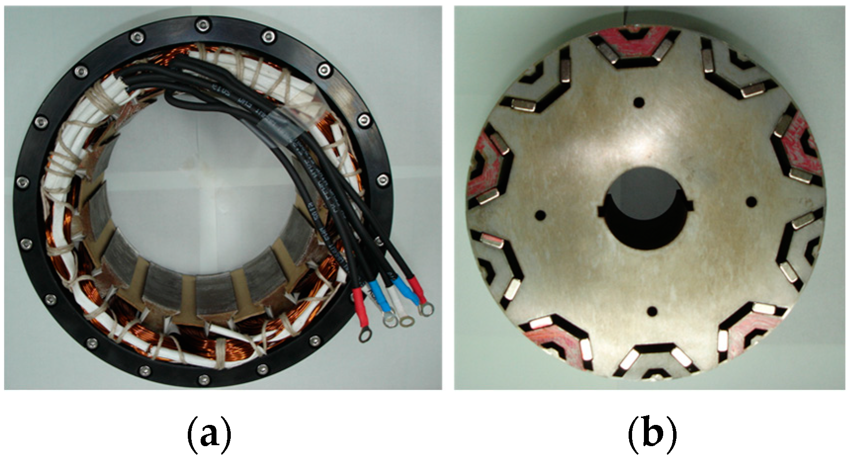
Figure 11.
Manufactured motor: (a) stator; (b) rotor.

Figure 12.
Experimental setup for testing.

Figure 13.
Torque curves at 480 r/min and 10 Arms for fundamental-controlled operation.

Figure 14.
A-phase current FFT magnitude plot at (a) 10 Arms and (b) 5 Arms.

Figure 15.
Torque curves at 480 r/min and 5 Arms for fundamental-controlled operation.

Figure 16.
A comparison of current waveforms optimized for the actual fundamental-controlled operation (a) at 10 Arms and (b) 5 Arms.
Figure 16.
A comparison of current waveforms optimized for the actual fundamental-controlled operation (a) at 10 Arms and (b) 5 Arms.

Figure 17.
Torque curves at 480 r/min and 10 Arms for fifth-harmonic injection-controlled operation.
Figure 17.
Torque curves at 480 r/min and 10 Arms for fifth-harmonic injection-controlled operation.

Figure 18.
A-phase current FFT magnitude plot at (a) 10 and (b) 5 Arms.

Figure 19.
Torque curves at 480 r/min and 5 Arms for fifth-harmonic injection-controlled operation.

Figure 20.
Transient state of controlled methods at 480 r/min.


Table 1.
Optimization results of various harmonic injection coefficients.
| Parameters | 5th + 7th Injection | 5th Injection | 7th Injection | Fundamental |
|---|---|---|---|---|
| 1.0726 | 1.0462 | 1.0231 | 1.0 | |
| 0.1073 | 0.0472 | - | - | |
| 0.0347 | - | 0.0236 | - | |
| 180° | 180° | - | - | |
| 180° | - | 0° | - |
Table 2.
Design specifications of a six-phase PMSM.
| Design Specification | Desired Operating Specification | ||
|---|---|---|---|
| Winding method | Concentrated | Line to line voltage [Vrms] | 120 |
| Number of phases | 6 | Rated currents [Arms] | 10 |
| Poles/slots | 10/12 | Rated torque [Nm] | 16 |
| Core material | 35PN230 | Rated speed [r/min] | 480 |
| Magnet material | N45H/1.4[T] | Max speed [r/min] | 1800 |
Table 3.
FEM simulation results for phase stator current and output torque according to harmonic injection methods.
Table 3.
FEM simulation results for phase stator current and output torque according to harmonic injection methods.
| Parameters | 5th + 7th Injection | 5th Injection | 7th Injection | Fundamental | ||||
|---|---|---|---|---|---|---|---|---|
| 1.0726 | 1.0462 | 1.0231 | 1 | |||||
| 0.1073 | 0.0472 | - | - | |||||
| 0.0347 | - | 0.0236 | - | |||||
| Max. current [A] | 14.14 | 7.07 | 14.14 | 7.07 | 14.14 | 7.07 | 14.14 | 7.07 |
| Min. current [A] | −14.14 | −7.07 | −14.14 | −7.07 | −14.14 | −7.07 | −14.14 | −7.07 |
| RMS current [Arms] | 10.78 | 5.39 | 10.47 | 5.23 | 10.23 | 5.11 | 10.00 | 5 |
| Mean torque [Nm] | 17.67 | 8.54 | 17.24 | 8.34 | 16.84 | 8.17 | 16.43 | 7.97 |
| Ripple factor [%] | 15.16% | 18.72% | 9.88% | 13.11% | 6.53% | 10.17% | 6.19% | 10.16% |
Table 4.
The experimental instruments.
| Instrument | Model |
|---|---|
| Servo motor | HD-805 |
| Torque sensor | M425-S1 C |
| Oscilloscope | 6510e |
| DC power supply | 500 V 30 A (15 kW) |
| 3 ph Inverter ×2 | Semikron AN-8005 |
| DSP | F28379D |
| JTAG emulator | XDS100 ver 3.0 |
Table 5.
Optimized experimental harmonics coefficient.
| Parameters | 5th Injection (10 Arms_5 Deg) | 5th Injection (5 Arms_5 Deg) |
|---|---|---|
| 1.04 | 1.026 | |
| 0.0743 | 0.0876 | |
| 180° | 180° |
Table 6.
System efficiency for each controlled method at 480 r/min.
| Parameters | Fundamental (5 Arms_5 Deg) | Fundamental (10 Arms_5 Deg) | 5th Injection (5 Arms_5 Deg) | 5th Injection (10 Arms_5 Deg) |
|---|---|---|---|---|
| Input power [w] | 508.06 | 1129.81 | 538.48 | 1199.91 |
| Output power [w] | 439.79 | 977.01 | 467.70 | 1043.89 |
| Efficiency | 86.56% | 86.47% | 86.85% | 86.99% |
Publisher’s Note: MDPI stays neutral with regard to jurisdictional claims in published maps and institutional affiliations. |
© 2022 by the authors. Licensee MDPI, Basel, Switzerland. This article is an open access article distributed under the terms and conditions of the Creative Commons Attribution (CC BY) license (https://creativecommons.org/licenses/by/4.0/).
Share and Cite
MDPI and ACS Style
Yun, D.; Kim, N.; Hyun, D.; Baek, J. Torque Improvement of Six-Phase Permanent-Magnet Synchronous Machine Drive with Fifth-Harmonic Current Injection for Electric Vehicles. Energies 2022, 15, 3122. https://doi.org/10.3390/en15093122
AMA Style
Yun D, Kim N, Hyun D, Baek J. Torque Improvement of Six-Phase Permanent-Magnet Synchronous Machine Drive with Fifth-Harmonic Current Injection for Electric Vehicles. Energies. 2022; 15(9):3122. https://doi.org/10.3390/en15093122
Chicago/Turabian StyleYun, Donghan, Namhun Kim, Daeil Hyun, and Jeihoon Baek. 2022. "Torque Improvement of Six-Phase Permanent-Magnet Synchronous Machine Drive with Fifth-Harmonic Current Injection for Electric Vehicles" Energies 15, no. 9: 3122. https://doi.org/10.3390/en15093122
Note that from the first issue of 2016, this journal uses article numbers instead of page numbers. See further details here.