
SOC Balancing and Coordinated Control Based on Adaptive Droop Coefficient Algorithm for Energy Storage Units in DC Microgrid


1
College of Electric Power, Inner Mongolia University of Technology, Hohhot 010080, China
2
Inner Mongolia Regional Key Laboratory of Electrical Power Conversion, Transmission and Control, Hohhot 010080, China
*
Author to whom correspondence should be addressed.
Energies 2022, 15(8), 2943; https://doi.org/10.3390/en15082943
Submission received: 28 February 2022
/
Revised: 11 April 2022
/
Accepted: 15 April 2022
/
Published: 17 April 2022
(This article belongs to the Special Issue Microgrids and the Integration of Energy Storage Systems)
Abstract
:In order to achieve a state-of-charge (SOC) balance among multiple energy storage units (MESUs) in an islanded DC microgrid, a SOC balancing and coordinated control strategy based on the adaptive droop coefficient algorithm for MESUs is proposed. When the SOC deviation is significant, the droop coefficient for an energy storage unit (ESU) with a higher (or lower) SOC is set to a minimum value when discharging (or charging). The ESU with the higher (or lower) SOC is controlled to discharge (or charge) with the rated power, while the other ESU compensates for the remaining power when the demanded discharging (or charging) power is greater than the rated power of the individual ESU. Otherwise, when the demanded discharging (or charging) power is lower than the rated power of either ESU, the ESU with the higher (or lower) SOC releases (or absorbs) almost all the required power while the other ESU barely absorbs or releases power, thus quickly realizing SOC balancing. When the SOC deviation is slight, the fuzzy logic algorithm dynamically adjusts the droop coefficient and changes the power distribution relationship to balance the SOC accurately. Furthermore, a bus voltage recovery control scheme is employed to regulate the bus voltage, thus improving the voltage quality. The energy coordinated management strategy is adopted to ensure the power balance and stabilize the bus voltage in the DC microgrid. A simulation model is built in MATLAB/Simulink, and the simulation results demonstrate the effectiveness of the proposed control strategy in achieving fast and accurate SOC balance and regulating the bus voltage.
1. Introduction
Due to the intermittence of renewable energy sources and unpredictable load fluctuations, instantaneous power imbalances are caused. An energy storage system (ESS) is usually used to provide energy support and enhance the system’s reliability [1,2,3,4]. To meet the power rating of the corresponding converter and ensure the safety and reliability of the ESS, multiple energy storage units (MESUs) are required to be configured into an ESS. When the line impedances and real capacities are different, state-of-charge (SOC) deviation among MESUs is produced [5,6,7]. Maintaining SOC balance can avoid the overcharging and over-discharging of MESUs and maximize the available energy storage capacity and charging/discharging rates [8,9,10].
The battery SOC balancing control strategy based on multi-agent is proposed in [11]. The proposed SOC balancing strategy has a plug-and-play capability. Moreover, different capacities of batteries and the decline in the battery capacity after a long-term operation are considered in the control strategy. In [12], the total reflected capacity in the system is estimated by summing the reflected capacity, SOC, and Ah rating of each battery. The total reflected capacity divided by the reference current from the controller gives the reference time for each battery to discharge or charge. In [13], to balance the SOCs of all energy storage units (ESUs), the reference current of each ESU is obtained by a fuzzy controller with SOC and DC-link voltage as inputs.
Droop control is a popular current sharing method in the primary control layer, especially for islanded low-voltage DC microgrids [14,15,16]. The droop control has been widely applied in DC microgrids [17,18]. In [19], the droop coefficient, inversely proportional to the nth order of SOC, is used to balance the SOCs of ESUs in the DC microgrid. The ESUs with a higher SOC can be controlled to deliver more power, whereas those with a lower SOC deliver less power. In [20], the double-quadrant SOC-based droop control method is used. In the charging/discharging process, the droop coefficient is positively/inversely proportional to the nth order of SOC. In [21], a new decentralized strategy is proposed to balance the SOC of each ESU. The virtual resistance of the droop controller is modified by the fuzzy controller, so the battery with the lowest SOC is charged faster than others. In [22], the droop resistance is adjusted based on the exponential function of the difference between an individual battery’s SOC and the average SOC of all the batteries in a DC microgrid. In [23], a highly accurate power-sharing method is presented to balance the SOC. In this method, the objective of the PI controller is to regulate the SOC of each battery equal to the average SOC. The nominal voltage reference of droop control is adjusted by sliding mode control to achieve SOC balancing [24,25]. In [26], a secondary control based on a consensus algorithm has been proposed to regulate the DC-bus voltage reference and balance the SOC of ESUs. In [27], a SOC balancing scheme considering different SOCs, and capacities is achieved by a high-pass-filter-based SOC balancing method. However, under the larger SOC deviation, the above control methods do not consider accelerating SOC balance by controlling ESUs with higher SOC to discharge at maximum power (or to charge at minimum power) or ESUs with lower SOC to charge at maximum power (or to discharge at minimum power).
In order to quickly and accurately balance the SOCs of MESU and ensure stable operation of the DC microgrid, SOC balancing and coordinated control based on an adaptive droop coefficient algorithm are proposed in this paper. The fuzzy logic algorithm does not need the system model. However, it relies on the knowledge formulated by an experienced operator or expert to achieve the control objectives. This paper adopts the fuzzy logic algorithm to dynamically adjust the droop coefficients to realize a more accurate SOC balancing control. The main contributions of this paper are summarized as follows:
- (1)
- The droop coefficient of ESUs with higher/lower SOC under discharge/charge is regulated to a minimum value in the case of a significant SOC deviation. SOCs can be balanced quickly;
- (2)
- The droop coefficient is automatically adjusted by the fuzzy logic algorithm to accurately balance SOC in the case of a slight SOC deviation;
- (3)
- The DC bus voltage recovery control is adopted to eliminate the voltage error caused by the traditional droop control, realizing automatic recovery control of the bus voltage;
- (4)
- To ensure the power balance and stabilize the bus voltage, the energy coordinated management strategy based on SOC balancing of the DC microgrid has been adopted.
2. Analysis of the SOC Unbalance
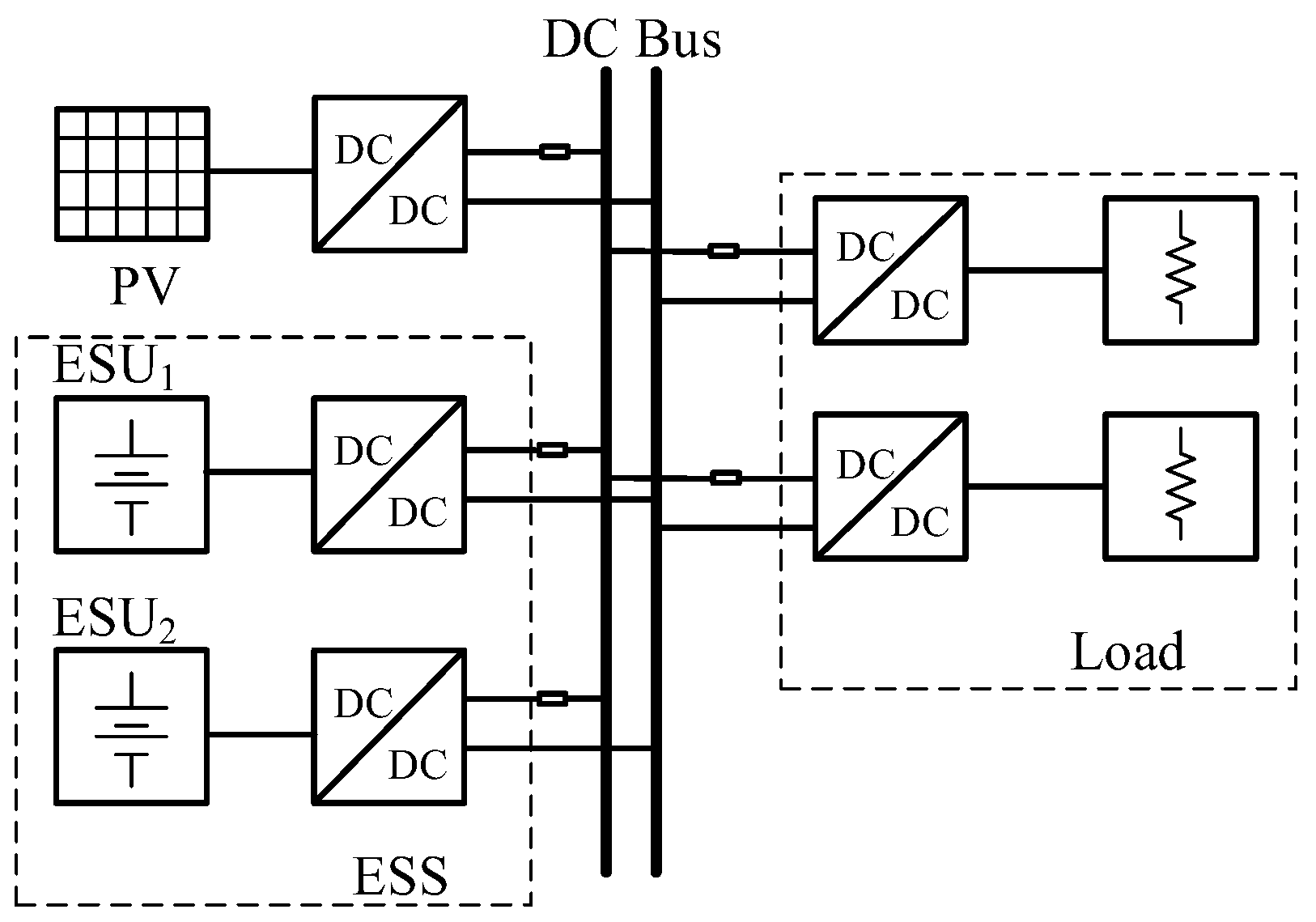
The studied islanded DC microgrid system is depicted in Figure 1 [28]. The photovoltaic (PV) power generation system provides energy to the DC bus. The two ESUs absorb the excess power from or release power to the bus to achieve the bus voltage stability and supply the load.
In the DC microgrid, the droop control can be expressed by the following:
where Uref and Uout are the reference and actual output voltages of the DC/DC converter; k represents the droop coefficient; Iout is the output current of the DC/DC converter.
SOC of the battery is the follows:
where SOC0 is the SOC initial value; Ce and i represent the capacity and output current; η denotes the battery efficiency.
Considering the line impedance and using (1), current i can be written as follows:
where Rline is line impedance.
Combining (2) and (3), the changing rates of SOCs of the two batteries are given by the following:
where k1, 2, Rline1, 2, and Uref1, 2 are the droop coefficient, line impedance, and output voltage reference of ESU1 and ESU2.
Further, one can obtain
It is known from (5) that SOC deviation would be created when the actual capacity, droop coefficient, or line impedance of these MESU are different.
3. The SOC Balancing Strategy Based on Adaptive Droop Coefficient Algorithm
3.1. The Adaptive Droop Coefficient Algorithm
The average SOC and SOC deviation are shown in (6) and (7).
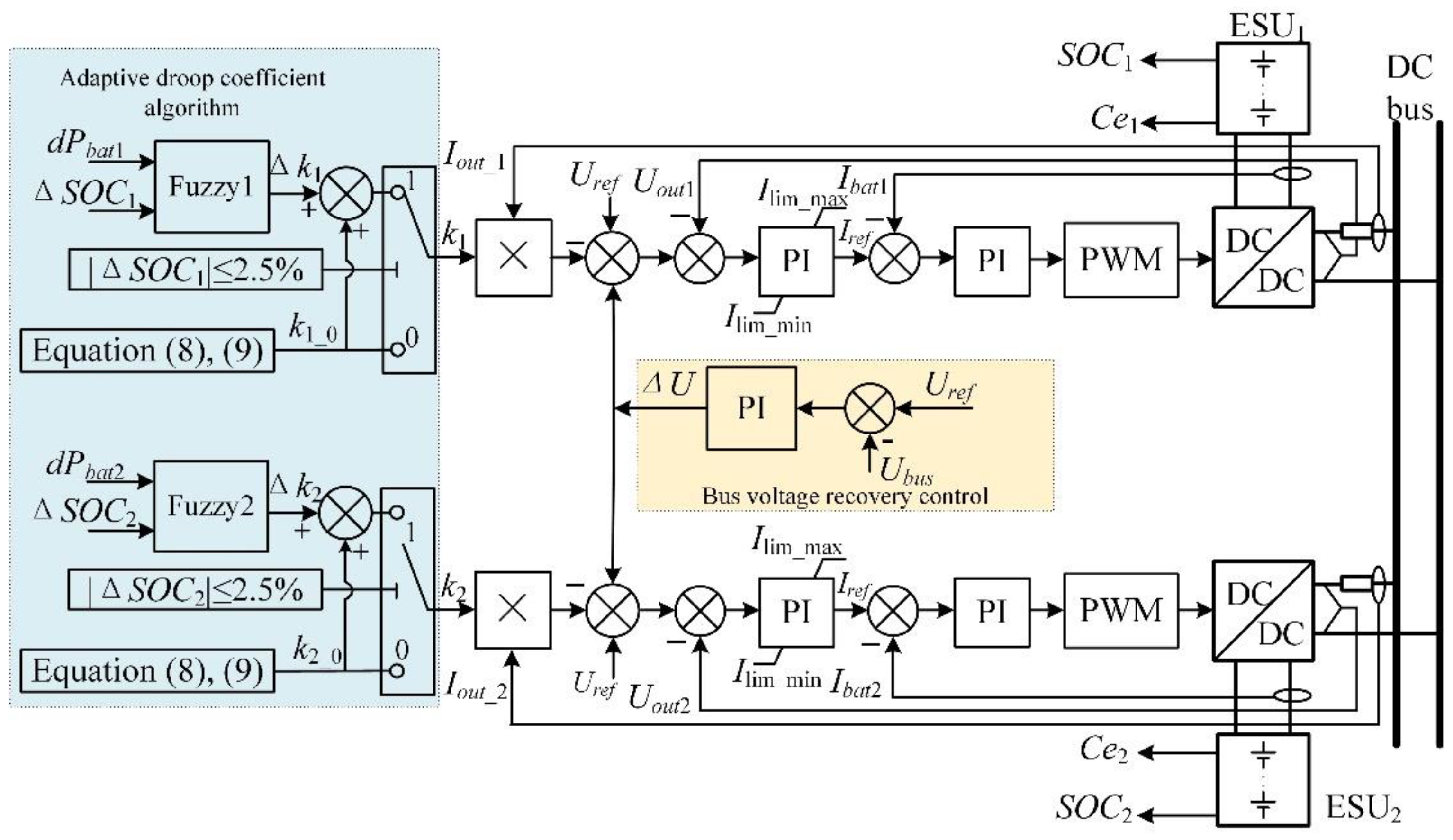
The SOC balancing strategy based on the adaptive coefficient algorithm is shown in Figure 2, and explanations are described below.
- (1)
- |∆SOCi|>2.5%
When the SOC deviation is significant (i.e., |∆SOCi|>2.5%), to accelerate SOC equalization, the droop coefficient is set as follows;
In the charging process, as follows:
where ki_0 represents the initial coefficient; i = 1, 2; kmin and kmax are the minimum and maximum values of the droop coefficient; SOCmax is the maximum value of SOC.
In the discharging process, as follows:
The PI limiter of the outer loop is the following:
The droop coefficients are set according to (8) and (9). In combination with the outer loop limiter, the following two goals can be achieved:
(a) If the power to be released reaches Pdmax ≤ P < 2Pdmax or the power to be absorbed reaches Pcmax ≤ P < 2Pcmax, the battery with the lower (higher) SOC absorbs (releases) the rated power when charging (discharging). The other units compensate for the residual power automatically. Here, Pdmax and Pcmax represent the rated discharging and charging power;
(b) If the power to be released reaches P < Pdmax or the power to be absorbed reaches P < Pcmax, the battery with lower (higher) SOC absorbs (releases) all power when charging (discharging), and the other unit’s output power is nearly zero.
- (2)
- |∆SOCi| ≤ 2.5%
When the SOC deviation is slight (i.e., |∆SOCi| ≤ 2.5%), the droop coefficient is adjusted by the fuzzy control algorithm to balance the SOCs accurately. The ESUs’ droop coefficient can be expressed as follows:
where Δki is the droop coefficient increment and it is determined by the fuzzy control algorithm; ki_0 is set as the same as when |∆SOCi|>2.5%.
The fuzzy control algorithm generates a droop coefficient increment according to the power deviation and the SOC deviation of ESUs to adjust the drooping coefficient and realize SOC balance control.
3.2. Design of the Fuzzy Logic Algorithm
The fuzzy control method has the advantage of not requiring an accurate model and adaptively modifying the key parameters according to the designed fuzzy rules [29,30,31]. Therefore, the fuzzy control algorithm is used to adjust the droop coefficient to achieve accurate SOC balancing when the SOC deviation is slight.
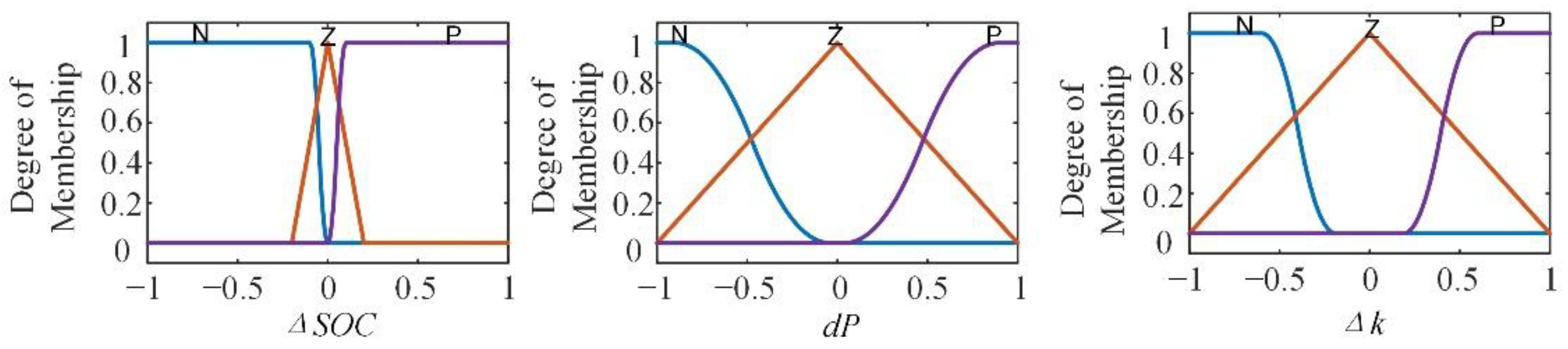
The variation of the droop coefficient determines the amount of power absorbed or released by each ESU, thus affecting the variation of SOC. Therefore, the deviations in power and SOC between ESUs are selected as the inputs of the fuzzy control algorithm. The corresponding relationship between the physical and fuzzy domains of variables for the fuzzy control algorithm is shown in Table 1.
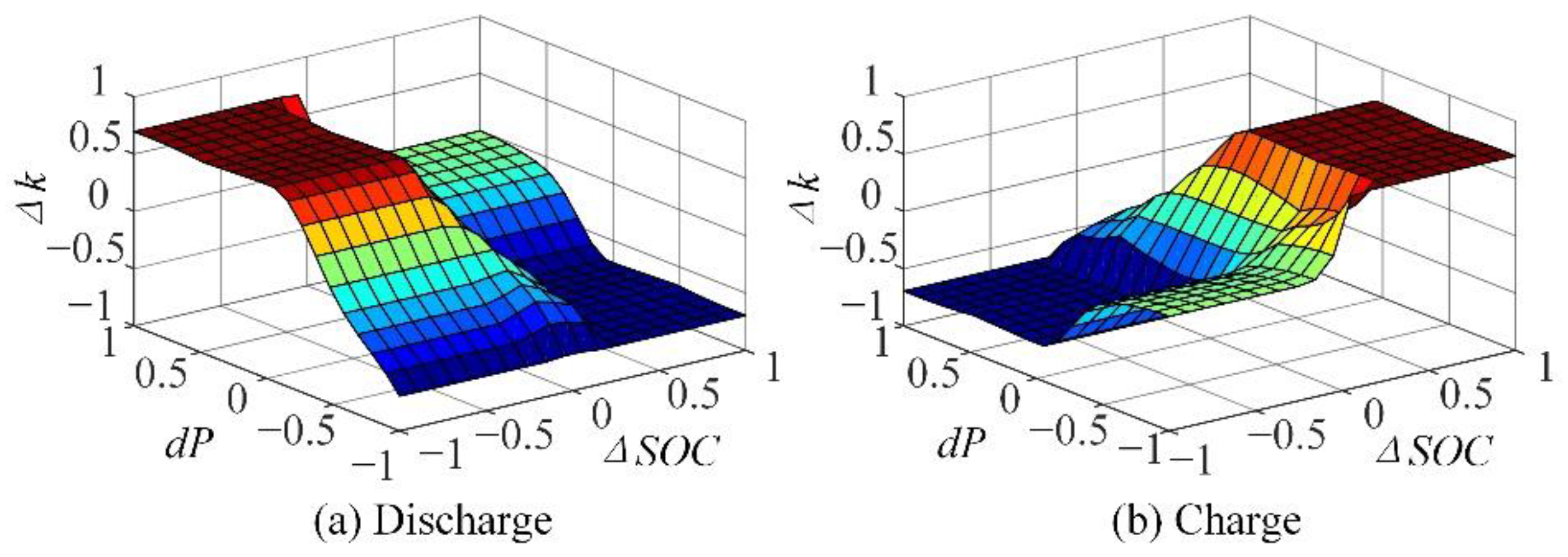
The membership functions of the input variables and output variables of the fuzzy controller are shown in Figure 3. The variables of ΔSOC, dP, and Δk are mapped to three different fuzzy subsets according to the control experience. The fuzzy control rules can be designed according to the experiences shown in Table 2. According to the membership function, and 18 different fuzzy rules in the charging and discharging state, the normalized control surface can be obtained after defuzzification by the centroid method, as shown in Figure 4.
3.3. Bus Voltage Recovery Control
A voltage deviation equal to kIout is always produced in the traditional droop control. More power transmission leads to more bus voltage drops. Therefore, a bus voltage recovery control is added to overcome the bus voltage drop caused by the traditional droop control and ensure the stability of bus voltage.
Bus voltage can be expressed by the following:
where Ubus is bus voltage, and Kp and Ki are the proportional and integral coefficients of the PI regulator.
The DC bus voltage (kIout) is compensated by the output voltage (∆U). When the system reaches a steady state, the bus voltage (Ubus) can be controlled to equal the given voltage (Uref). Therefore, the DC bus voltage without control error is realized.
3.4. Simulation Waveforms of SOC Balancing Control
A simulation model is built based on MATLAB/Simulink R2021b from MathWorks (Corporate Headquarters Natick, MA, USA) and parameters are shown in Table 3 [28]. In simulation settings, the solver is set to ode23tb and the step size is 2 μs.
- (1)
- ESU-discharging waveforms
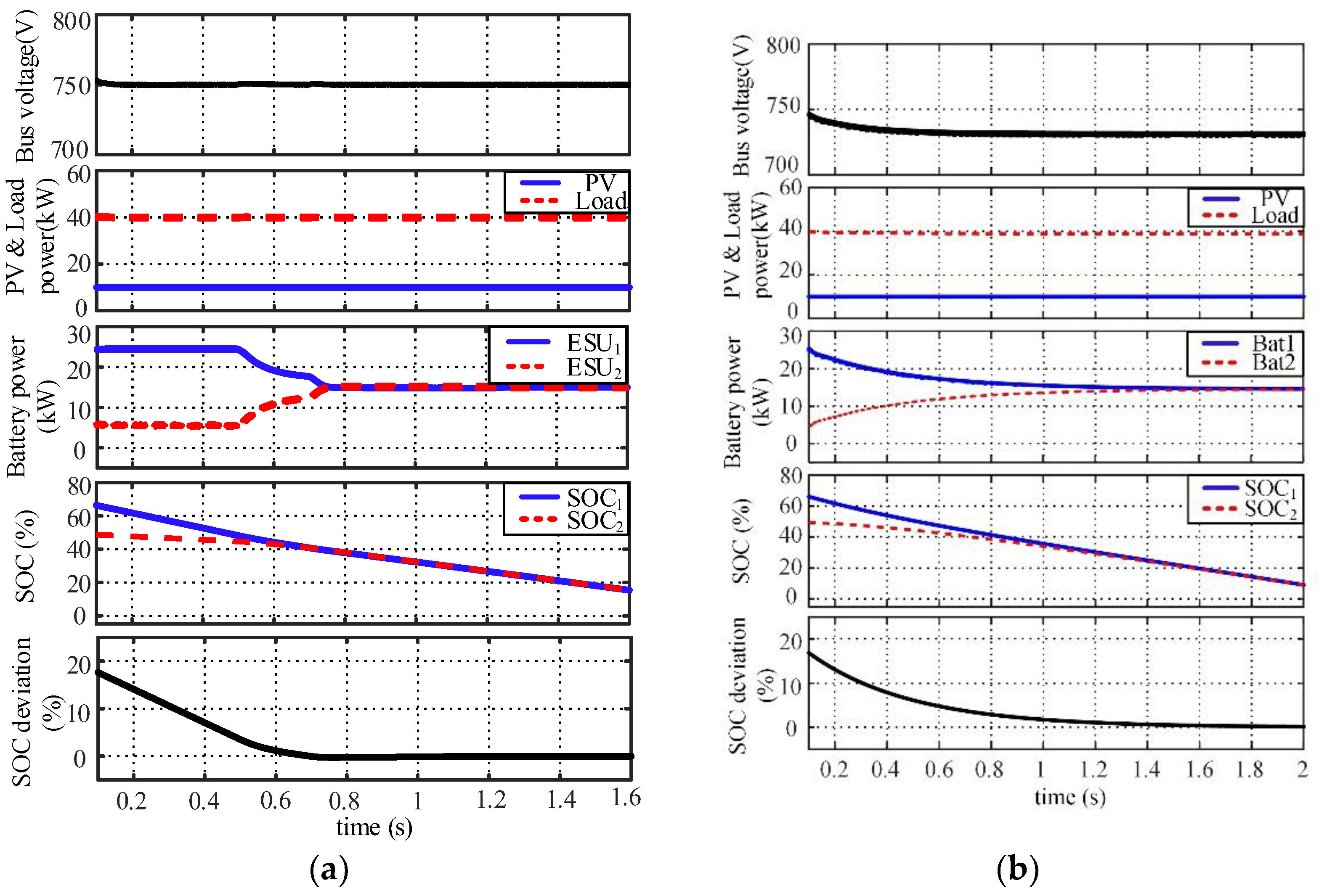
Figure 5 presents the comparative simulation results of the proposed method with the method in [32]. The discharging power of ESS is Pdmax ≤ P < 2Pdmax, and PV and load power are 10 kW and 40 kW. To maintain the power balance within the DC microgrid, the ESS needs to release 30 kW, which is more than the maximum discharging power (25 kW) of an ESU. The initial SOCs of the two ESUs are 70% and 50%. As observed in Figure 5a, when the SOC deviation of two ESUs is larger than 2.5% (before 0.45 s), ESU1 outputs the maximum allowable discharging power of 25 kW since it has a larger SOC. The remaining 5 kW power shortage is provided by ESU2. The SOC deviation of the two ESUs is decreased to less than 2.5% after 0.45 s. Eventually, the SOC deviation is eliminated.
As seen in Figure 5b, the coefficients are getting close due to the decrease in SOC deviation. Thus, the output powers of the two batteries also get close, and together they output 30 kW all the time. The SOC deviation is eliminated at around 1.8 s, and it is much slower than the proposed method shown in Figure 5a.
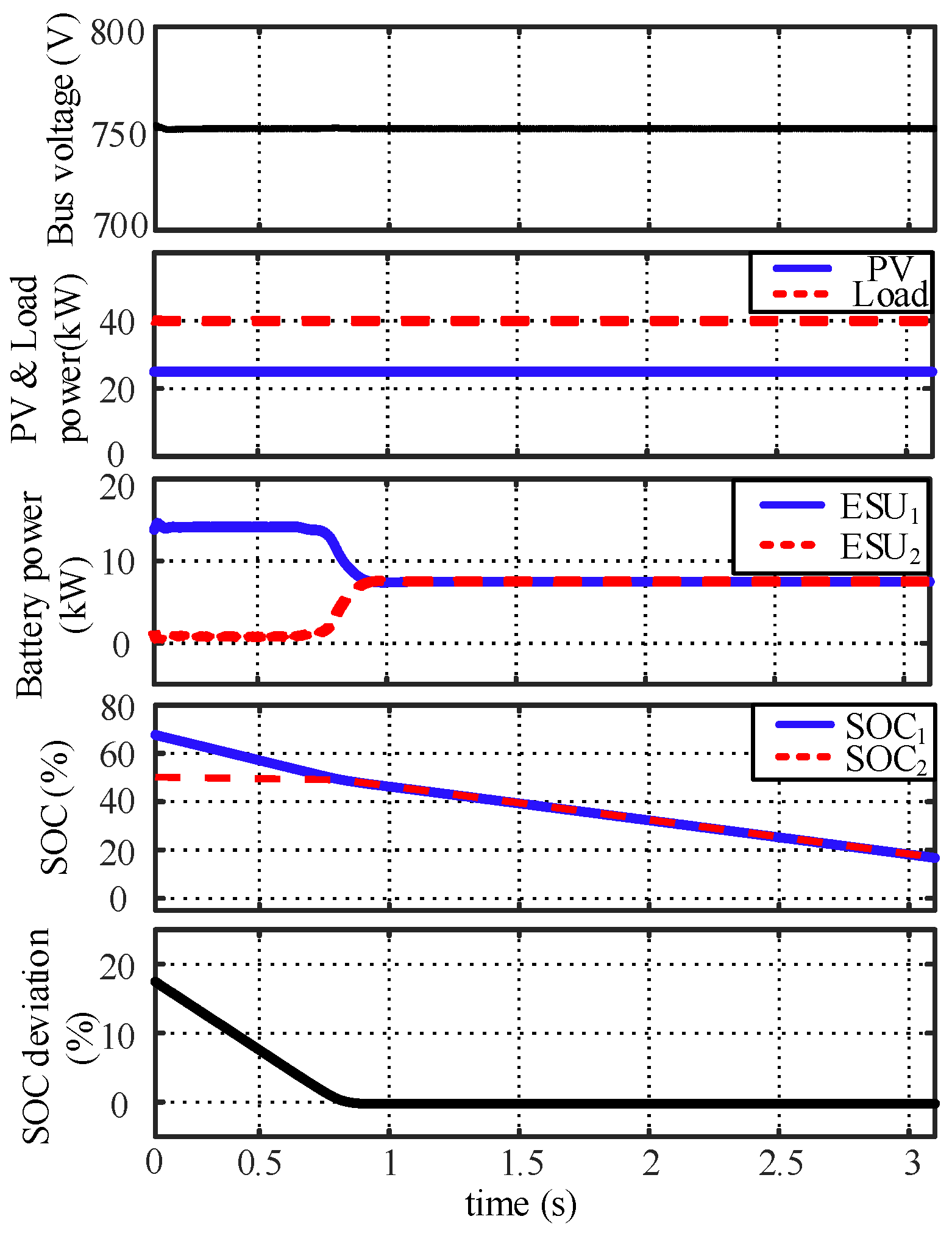
When the discharging power ESS is P ≤ Pdmax, the simulation results are shown in Figure 6. In Figure 6, ESU1 outputs 15 kW of power of the total shortage in the system, and the output power of ESU2 is nearly 0. The SOC of the two ESUs is balanced at 0.9 s.
As can be seen from Figure 5 and Figure 6, the SOCs can be balanced quickly. The voltage deviation can be eliminated automatically under the voltage recovery control. Finally, the bus voltage is recovered to 750 V, following the defined voltage reference.
- (2)
- ESU-charging waveforms
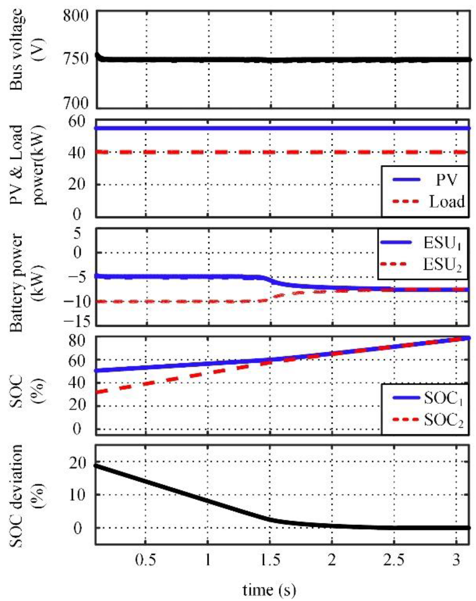
In Figure 7, PV and load powers are 55 kW and 40 kW, respectively, and there is a 15 kW deficit in the microgrid, larger than the maximum charging power of an EUS. The SOCs of the two ESUs are 50% and 30%. The ESU2 has a lower SOC, and it is charged with the rated power of 10 kW, while the other 5 kW of power is charged to the ESU1. At 1.6 s, the controller is switched to the fuzzy controller to approach the droop coefficient. At 2.4 s, the SOCs of the two ESUs are balanced.
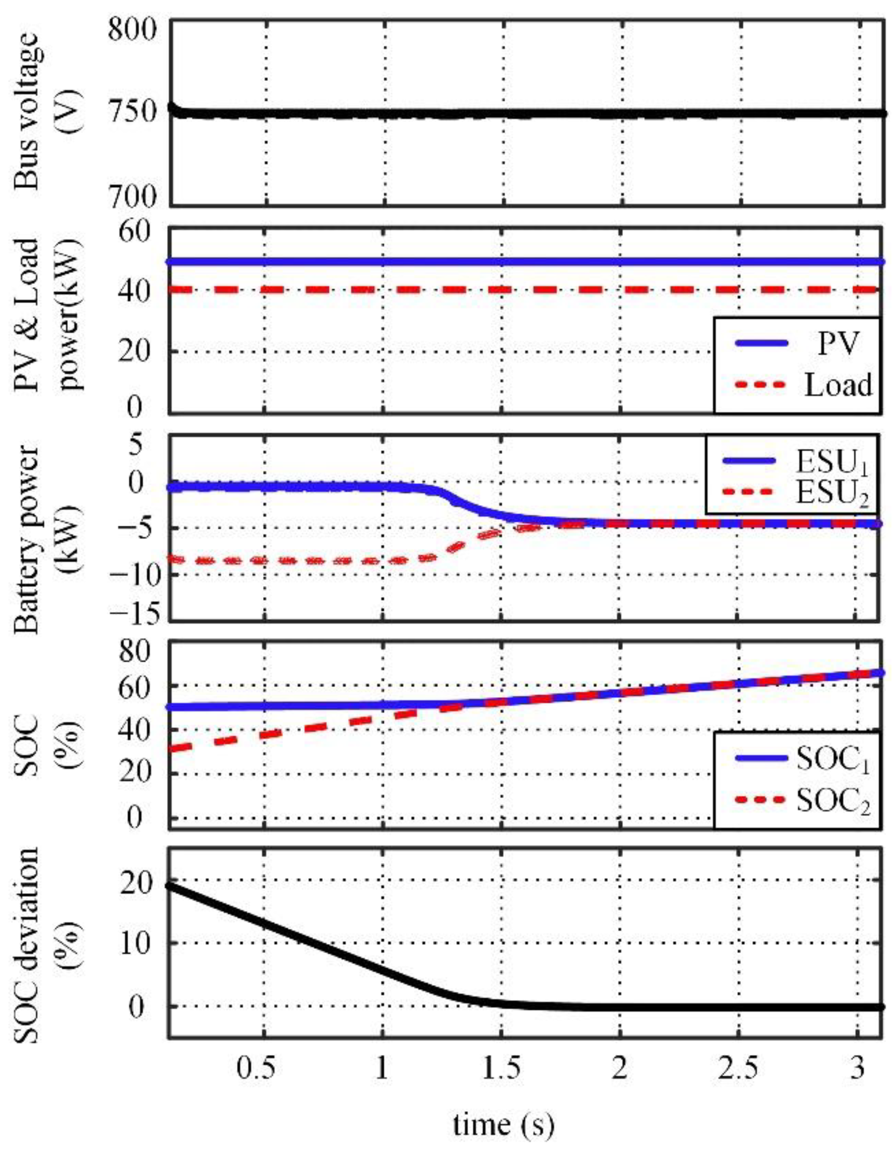
In Figure 8, the PV outputs 49 kW of power, but the load only absorbs 40 kW. There is 9 kW of power remaining in the system, and it is less than the rated power of an individual ESU. ESU1 has a higher SOC, so it barely absorbs power. ESU2 absorbs all 9 kW of power since it has a lower SOC. The SOC balancing of two ESUs is achieved at 1.5 s, as seen in Figure 8.
It can be concluded from the above descriptions that the proposed method has superior performance.
① In terms of significant SOC deviation.
When the demanded discharging or charging power is greater than the rated power of an individual ESU, with the proposed method, one ESU is charged or discharged with the rated power while the other ESU compensates for the remaining power. When the demanded charging or discharging power is smaller than the rated power of an individual ESU, one ESU is charged or discharged with the required power while the other remains on standby to balance the power in the system. Therefore, the proposed method can achieve a fast SOC balance.
② In terms of slight SOC deviation.
The droop coefficient is adjusted dynamically by the fuzzy logic algorithm to achieve accurate SOC balance.
4. Coordinated Control Based on the Piecewise Adaptive Algorithm
4.1. Coordinated Control Diagram of DC Microgrid
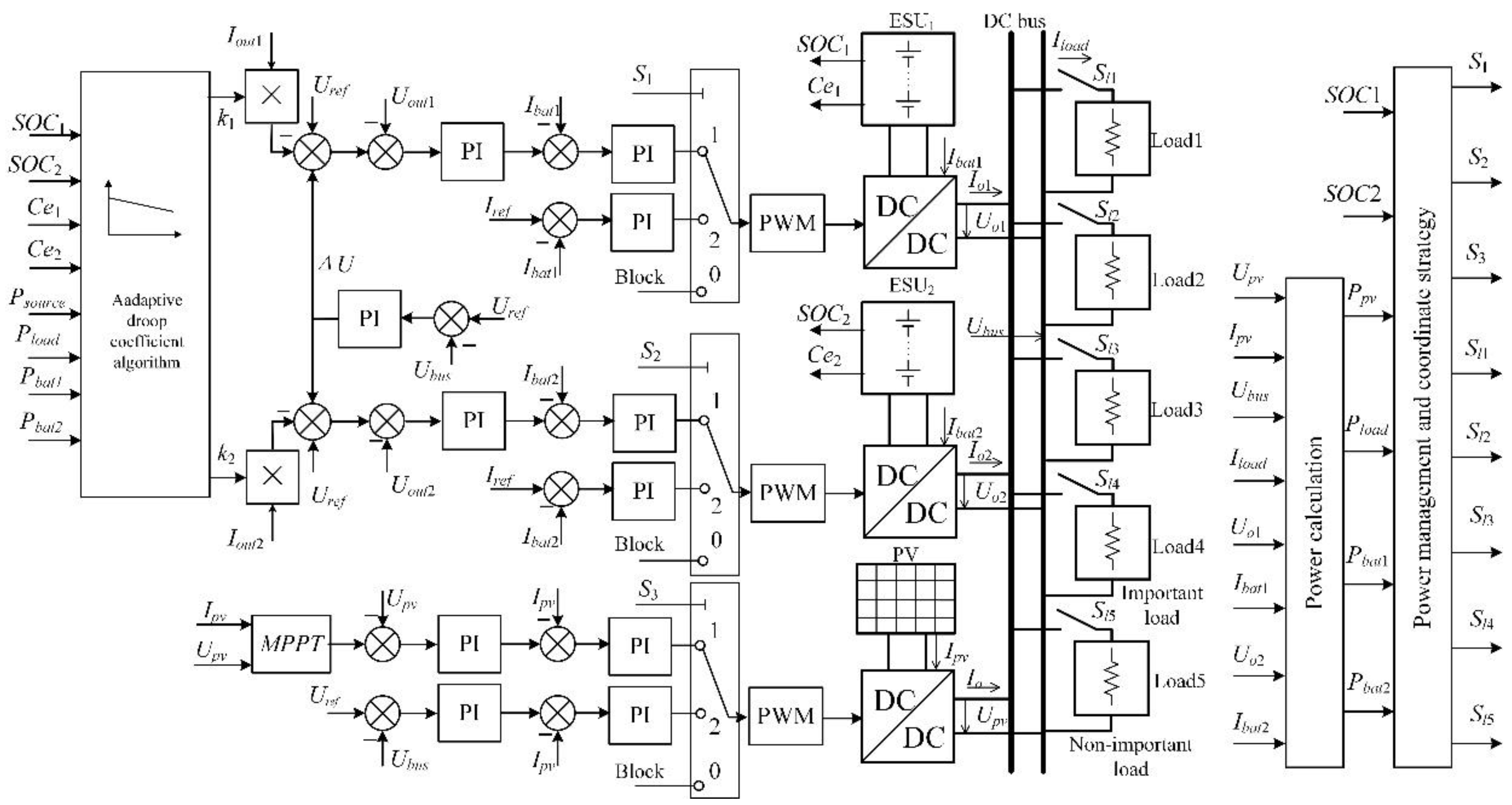
The coordinated control diagram of the DC microgrid is shown in Figure 9.
4.2. Power Management and Coordinated Control Strategy
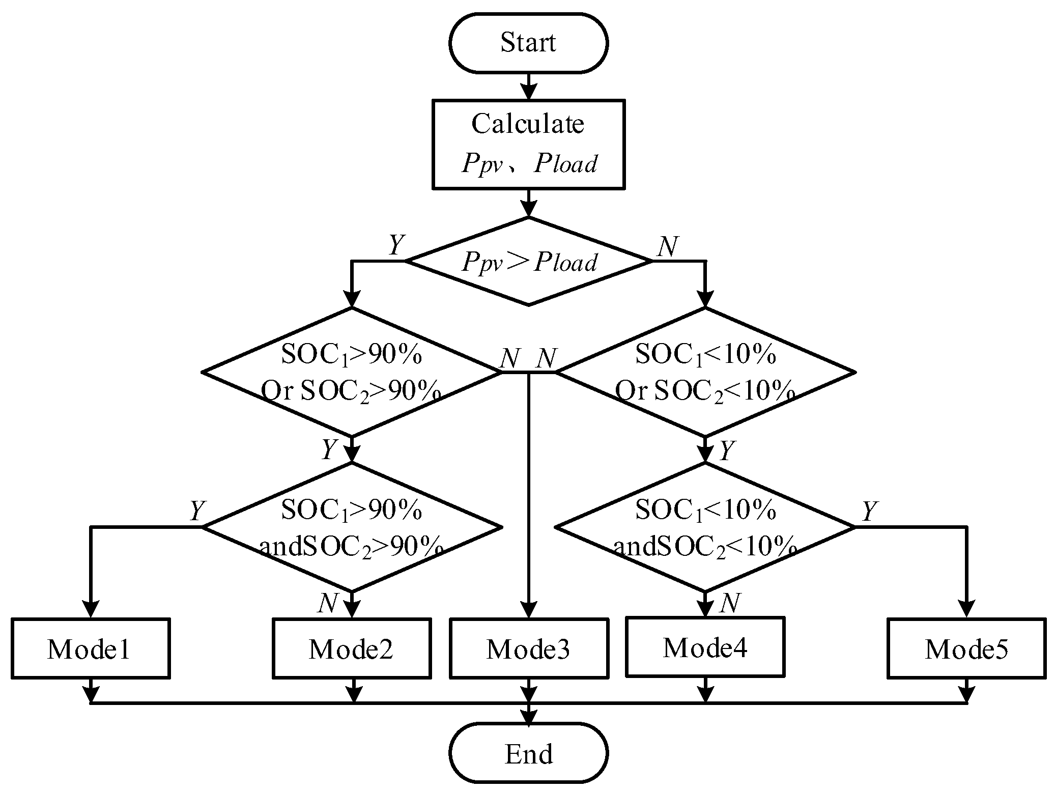
The operation of the DC microgrid can be divided into the following five operation modes according to different conditions of PV, MESU, and loads:
Mode1: The PV is controlled by the constant voltage control (CVC); the ESU is on standby; basic loads are supplied;
Mode2: ① When the residual power is greater than the maximum power of the ESU, the PV is controlled by CVC. The batteries whose SOCs do not reach the limit are controlled to absorb constant power, while those whose SOCs reach the limit are on standby. ② When the residual power is smaller than the maximum power of the ESU, the PV is regulated by the maximum power point tracking (MPPT) control, and the batteries stabilize the bus’s voltage or stay on standby;
Mode3: The PV is controlled by the MPPT control; the bus’s voltage is maintained by ESU; basic loads are supplied;
Mode4: ① When the shortage of power is greater than the maximum power of the ESU, the PV is controlled by the MPPT control. The batteries whose SOCs do not reach the limit are controlled to stabilize the bus’s voltage, while the one whose SOC reaches the limit is on standby; non-important loads are cut off in this scenario. ② When the power shortage is smaller than the maximum power of the ESU, the PV is regulated by the MPPT control and the batteries stabilize the bus voltage or stay on standby, supplying basic loads;
Mode5: The PV is controlled by the MPPT control; ESU is on standby; important loads are cut off gradually according to the PV power.
4.3. Simulation Waveforms of the Coordinated Control
- (1)
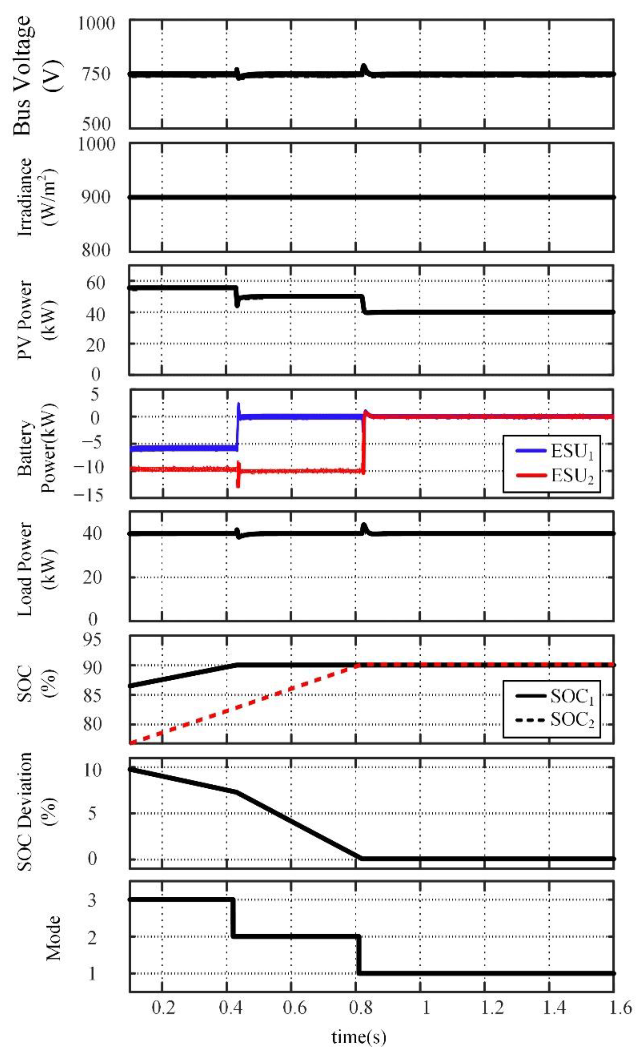
- Response to a sudden change of PV power
As shown in Figure 11, the initial SOC values are 85% and 75% for ESU1 and ESU2. Irradiance is constant at 900 W/m2; PV power is 58 kW with MPPT control; the load is constant at 40 kW. During these 0.1~0.42 s, the SOCs of the two ESUs do not reach 90%, and they keep the bus voltage constant. The system works in Mode3. At 0.42 s, SOC1 reaches 90%, and ESU1 is on standby. Simultaneously, the maximum PV power is 58 kW, and the load demand is only 40 kW. In order not to exceed the maximum allowable 10 kW charging power of the lithium battery, ESU2 is controlled to operate with a constant charging current. The PV power outputs 50 kW, and the system switches to control Mode2. During 0.42~0.81 s, ESU2 is continuously charged, and the bus voltage is controlled by the PV system. At 0.81 s, the SOC2 reaches 90%, and the charging power of ESU2 is 0. The PV outputs 40 kW, and the system is switched to Mode1.
- (2)
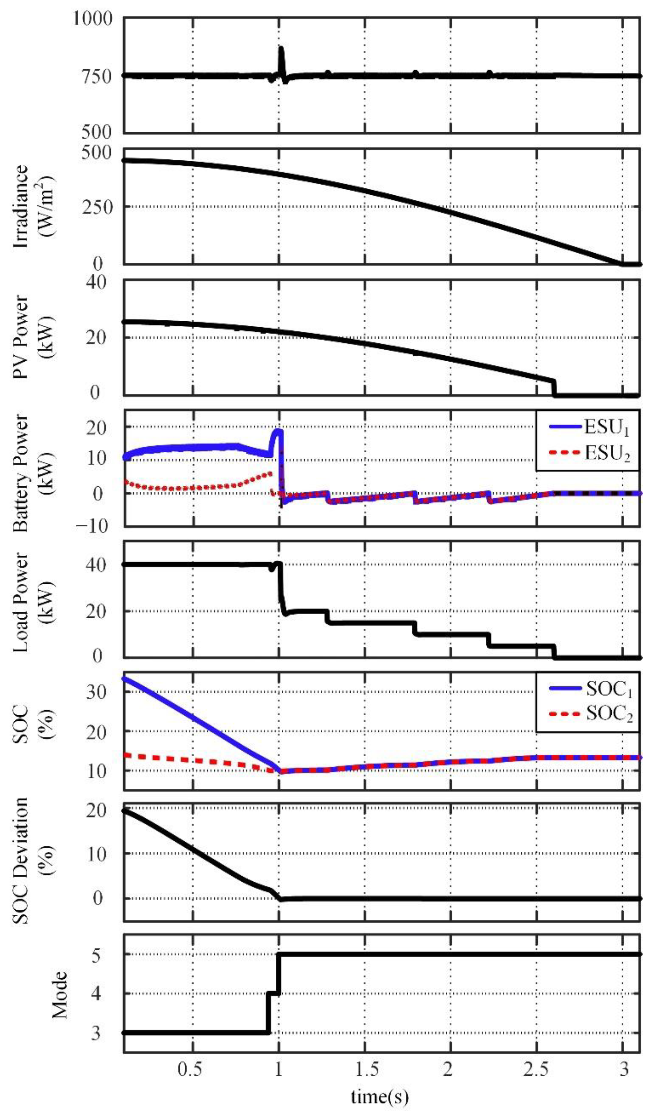
- Simulation results under removal of the load
As shown in Figure 12, irradiance is reduced from 450 W/m2 to 0 and the corresponding PV power is reduced from 25 kW to 0. The initial SOCs are set at 35% and 15%. Before 0.9 s, the maximum PV power was 27 kW, and the 13 kW of power shortage was allocated by the two ESUs, maintaining the bus voltage. The system works in Mode3 at this time. During these 0.9~1 s, ESU1 is on standby because SOC1 reaches the 10% minimum limit. The power shortage in the network is slightly less than 20 kW, which was all released by ESU2. At this time, the system is working in Mode4. After 1 s, the SOCs of both ESUs reach the lower limit (10%), so they are on standby. However, the maximum power of the PV cannot be maintained to supply the full basic loads. According to the power of PV and load, 20/5/5/5/5 kW load is cut off at 1/1.25/1.8/2.2/2.6 s according to their importance. The remaining power is used to charge the two ESUs. The system is running in Mode5 at this time.
5. Conclusions
This paper presents the SOC balancing and coordinated control strategy based on the adaptive droop coefficient algorithm for MESU. When the SOC deviation is relatively large, the droop coefficient of an ESU with a lower SOC is set to be the minimum value in the charging process. In the discharging process, the droop coefficient of an ESU with a higher SOC is set to be the minimum value. In the charging process, the ESU with a lower SOC absorbs energy with the rated power or all the charging power, while the one with a higher SOC absorbs the residual charging power or does not absorb any power. Meanwhile, in the discharging process, the ESU with a higher SOC delivers energy with rated power or all discharging power. The ESU with a lower SOC provides the rest of the charging power or does not deliver any power. Hence, rapid SOC balancing can be realized. When the SOC deviation is slight, the droop coefficient is adjusted smoothly and automatically by a fuzzy logic algorithm. The fuzzy logic algorithm adjusts the droop coefficient according to the inputs of the SOC deviation and output power of each ESU. Therefore, SOC deviation caused by the actual capacity and line impedance is eliminated, and accurate SOC balancing is achieved. The coordinated control of the DC microgrid is being studied to ensure the stable operation of the DC microgrid and the stability of bus voltage. The simulation results show that the proposed control strategy can realize the rapid SOC balance of multiple ESUs and maintain the bus voltage stability.
Author Contributions
Data curation, J.Z.; Formal analysis, Y.Z.; Investigation, G.T.; Methodology, Y.Z. and G.T.; Project administration, G.L.; Software, J.Z.; Supervision, G.T.; Validation, G.T.; Visualization, Y.Z.; Writing—original draft, Y.Z.; Writing—review and editing, G.T. All authors have read and agreed to the published version of the manuscript.
Funding
This work was funded by the National Natural Science Foundation of China (NO. 51767019, 51867020), the S&T Major Project of Inner Mongolia Autonomous Region under Grant (No. 2021ZD0040), the Inner Mongolia Science & Technology Plan under Grant (Research on key technology of multi-source coordinated control in islanded operation DC microgrid) and the Inner Mongolia Autonomous Region Natural Science Foundation under Grant (No. 2021MS05003, 2020BS05027).
Institutional Review Board Statement
Not applicable.
Informed Consent Statement
Not applicable.
Conflicts of Interest
The authors declare no conflict of interest.
References
- Li, L.; Dragičević, T.; Guerrero, J.M.; Vasquez, J.C. Supervisory control of an adaptive-droop regulated dc microgrid with battery management capability. IEEE Trans. Power Electron. 2014, 29, 695–706. [Google Scholar]
- Gao, F.; Kang, R.; Cao, J.; Yang, T. Primary and secondary control in dc microgrids: A review. Mod. Power Syst. Clean Energy 2019, 7, 227–242. [Google Scholar] [CrossRef] [Green Version]
- Han, Y.; Ning, X.; Yang, P.; Xu, L. Review of power sharing, voltage restoration and stabilization techniques in hierarchical controlled dc microgrids. IEEE Access 2019, 7, 149202–149223. [Google Scholar] [CrossRef]
- Yan, H.W.; Narang, A.; Tafti, H.D.; Farivar, G.G.; Ceballos, S.; Pou, J. Minimizing energy storage utilization in a stand-alone dc microgrid using photovoltaic flexible power control. IEEE Trans. Smart Grid 2021, 12, 3755–3764. [Google Scholar] [CrossRef]
- Morstyn, T.; Hredzak, B.; Agelidis, V.G. Control strategies for microgrids with distributed energy storage systems: An overview. IEEE Trans. Smart Grid 2018, 9, 3652–3666. [Google Scholar] [CrossRef] [Green Version]
- Madadi, M.; Bhattacharya, S. Adaptive nonlinear droop control with dynamic state-of-charge balancing capability for batteries in dc microgrids. In Proceedings of the IEEE Applied Power Electronics Conference and Exposition, Phoenix, AZ, USA, 14–17 June 2021; pp. 55–61. [Google Scholar]
- Yang, Y.; Tan, S.; Hui, S.Y.R. Mitigating distribution power loss of dc microgrids with dc electric springs. IEEE Trans. Smart Grid 2018, 9, 5897–5906. [Google Scholar] [CrossRef]
- Meng, T.; Lin, Z.; Wan, Y.; Shamash, Y.A. State-of-charge balancing for battery energy storage systems in dc microgrids by distributed adaptive power distribution. IEEE Control Syst. Lett. 2021, 6, 512–517. [Google Scholar] [CrossRef]
- Maharjan, L.; Inoue, S.; Akagi, H.; Asakura, J. State-of-charge (SOC)-balancing control of a battery energy storage system based on a. cascade PWM converter. IEEE Trans. Power Electron. 2009, 24, 1628–1636. [Google Scholar] [CrossRef]
- Huang, W.; Qahouq, J.A.A. Energy sharing control scheme for state-of-charge balancing of distributed battery energy storage system. IEEE Trans. Ind. Electron. 2015, 62, 2764–2776. [Google Scholar] [CrossRef]
- Hong, Y.; Xu, D.; Yang, W.; Jiang, B.; Yan, X.G. A novel multi-agent model-free control for state-of-charge balancing between distributed battery energy storage systems. IEEE Trans. Emerg. Top. Comput. Intell. 2021, 5, 679–688. [Google Scholar] [CrossRef]
- Bhosale, R.; Gupta, R.; Agarwal, V. A novel control strategy to achieve soc balancing for batteries in a dc microgrid without droop control. IEEE Trans. Ind. Appl. 2021, 57, 4196–4206. [Google Scholar] [CrossRef]
- Fagundes, T.A.; Fuzato, G.H.F.; Ferreira, P.G.B.; Biczkowski, M.; Machado, R.Q. Fuzzy controller for energy management and soc equalization in dc microgrids powered by fuel cell and energy storage units. IEEE J. Emerg. Sel. Top. Ind. Electron. 2022, 3, 90–100. [Google Scholar] [CrossRef]
- Liu, C.; Zhao, J.; Wang, S.; Lu, W.; Qu, K. Active identification method for line resistance in dc microgrid based on single pulse injection. IEEE Trans. Power Electron. 2018, 33, 5561–5564. [Google Scholar] [CrossRef]
- Zhi, N.; Ding, K.; Du, L.; Zhang, H. An SOC-based virtual dc machine control for distributed storage systems in dc microgrids. IEEE Trans. on Energy Convers. 2020, 35, 1411–1419. [Google Scholar] [CrossRef]
- Baharizadeh, M.; Golsorkhi, M.S.; Shahparasti, M.; Savaghebi, M. A two-layer control scheme based on P-V droop characteristic for accurate power sharing and voltage regulation in dc microgrids. IEEE Trans. Smart Grid 2021, 12, 2776–2787. [Google Scholar] [CrossRef]
- Braitor, A.C.; Konstantopoulos, G.C.; Kadirkamanathan, V. Current-limiting droop control design and stability analysis for paralleled boost converters in dc microgrids. IEEE Trans. Control Syst. Technol. 2021, 29, 385–394. [Google Scholar] [CrossRef]
- Zhang, Y.Y.; Qu, X.H.; Tang, M.D.; Yao, R.Y.; Wu, C. Design of nonlinear droop control in dc microgrid for desired voltage regulation and current sharing accuracy. IEEE J. Emerg. Sel. Top. Circuits Syst. 2021, 11, 168–175. [Google Scholar] [CrossRef]
- Lu, X.; Sun, K.; Guerrero, J.M.; Vasquez, J.C.; Huang, L. State-of-charge balance using adaptive droop control for distributed energy storage systems in dc microgrid applications. IEEE Trans. Ind. Electron. 2014, 61, 2804–2814. [Google Scholar] [CrossRef] [Green Version]
- Lu, X.; Sun, K.; Guerrero, J.M.; Vasquez, J.C.; Huang, L. Double-quadrant state-of-charge-based droop control method for distributed energy storage systems in autonomous dc microgrids. IEEE Trans. Smart Grid 2015, 6, 147–157. [Google Scholar] [CrossRef] [Green Version]
- Diaz, N.L.; Dragičević, T.; Vasquez, J.C.; Guerrero, J.M. Intelligent distributed generation and storage units for dc microgrids—a new concept on cooperative control without communications beyond droop control. IEEE Trans. Smart Grid 2014, 5, 2476–2484. [Google Scholar] [CrossRef] [Green Version]
- Oliveira, T.R.; Silva, W.W.A.G.; Donoso-Garcia, P.F. Distributed secondary level control for energy storage management in dc microgrids. IEEE Trans. Smart Grid 2017, 8, 2597–2607. [Google Scholar] [CrossRef]
- Hoang, K.D.; Lee, H. Accurate power sharing with balanced battery state of charge in distributed DC microgrid. IEEE Trans. Ind. Electron. 2019, 66, 1883–1893. [Google Scholar] [CrossRef]
- Morstyn, T.; Savkin, A.V.; Hredzak, B.; Agelidis, V.G. Multi-agent sliding mode control for state of charge balancing between battery energy storage systems distributed in a DC microgrid. IEEE Trans. Smart Grid 2018, 9, 4735–4743. [Google Scholar] [CrossRef] [Green Version]
- Xu, D.; Zhang, W.; Jiang, B.; Shi, P.; Wang, S. Directed-graph-observer-based model-free cooperative sliding mode control for distributed energy storage systems in dc microgrid. IEEE Trans. Ind. Inform. 2020, 16, 1224–1234. [Google Scholar] [CrossRef]
- Chen, X.; Shi, M.; Sun, H.; Li, Y.; He, H. Distributed cooperative control and stability analysis of multiple dc electric springs in a dc microgrid. IEEE Trans. Ind. Electron. 2018, 65, 5611–5622. [Google Scholar] [CrossRef]
- Lin, X.; Zamora, R.; Baguley, C.A. “A fully filter-based decentralized control with state of charge balancing strategy for battery energy storage systems in autonomous dc microgrid applications. IEEE Access 2021, 9, 15028–15040. [Google Scholar] [CrossRef]
- Zheng, Y.; Tian, G.; Zhang, J. SOC balancing control strategy based on piecewise adaptive droop coefficient algorithm for multienergy storage units in dc microgrid. In Proceedings of the IEEE 4th International Conference on Electronics Technology, Chengdu, China, 7–10 May 2021; pp. 432–436. [Google Scholar]
- Long, B.; Liao, Y.; Chong, K.T.; Rodríguez, J.; Guerrero, J.M. Enhancement of frequency regulation in ac microgrid: A fuzzy-MPC controlled virtual synchronous generator. IEEE Trans. Smart Grid 2021, 12, 3138–3149. [Google Scholar] [CrossRef]
- Coelho, V.N. A self-adaptive evolutionary fuzzy model for load forecasting problems on smart grid environment. Appl. Energy 2016, 169, 567–584. [Google Scholar] [CrossRef]
- Wang, Y.; Jin, Q.; Zhang, R. Improved fuzzy PID controller design using predictive functional control structure. ISA Trans. 2017, 71, 354–363. [Google Scholar] [CrossRef]
- Ghanbari, N.; Mobarrez, M.; Bhattacharya, S. A review and modeling of different droop control based methods for battery state of the charge balancing in dc microgrids. In Proceedings of the 44th Annual Conference of the IEEE Industrial Electronics Society, Washington, DC, USA, 21–23 October 2018; pp. 1625–1632. [Google Scholar]
Figure 1.
Topology of islanded DC microgrid.

Figure 2.
Diagram of the SOC balancing strategy.

Figure 3.
Membership function.

Figure 4.
Control surface. (a) Discharge; (b) Charge.

Figure 5.
Waveforms of Pdmax ≤ P< 2Pdmax in discharging. (a) Waveforms of the proposed method; (b) Waveforms of the method in [32].
Figure 5.
Waveforms of Pdmax ≤ P< 2Pdmax in discharging. (a) Waveforms of the proposed method; (b) Waveforms of the method in [32].

Figure 6.
Waveforms of P ≤ Pdmax in discharging.

Figure 7.
Waveforms of Pcmax ≤ P < 2Pcmax in charging.

Figure 8.
Waveforms of P ≤ Pcmax in charging.

Figure 9.
Coordinated control diagram of DC microgrid.

Figure 10.
Control mode selection flow diagram.

Figure 11.
Response to sudden change of PV power.

Figure 12.
Response to removal of the load.


Table 1.
Relationship between physical and fuzzy domain.
| Variables | Physical Domain | Quantization Factor | Fuzzy Domain |
|---|---|---|---|
| ΔSOC | [−50,50] | 0.02 | [−1,1] |
| dP | Charge: [−10,10] | 0.1 | [−1,1] |
| Discharge: [−25,25] | 0.04 | [−1,1] | |
| Δk | [−0.2,0.2] | 5 | [−1,1] |
Table 2.
Rules of fuzzy controller.
| ΔSOC | dP | Δk | |
|---|---|---|---|
| Charging | Discharging | ||
| P | P | N | Z |
| P | Z | P | N |
| P | N | P | N |
| Z | P | N | P |
| Z | Z | Z | Z |
| Z | N | P | N |
| N | P | N | P |
| N | Z | N | P |
| N | N | Z | N |
Table 3.
Main parameters of the system.
| Description | Value |
|---|---|
| Bus voltage Uout | 750 V |
| Capacitance Cout | 2000 μF |
| Inductance L | 2 mH |
| PV system | 55 kW |
| Important loads | 20 kW |
| Line impedance of ESU1 Rline1 | 0.03 Ω |
| Line impedance of ESU2 Rline2 | 0.05 Ω |
| Real capacity of ESU1 Ce1 | 133 Ah |
| Real capacity of ESU2 Ce2 | 130 Ah |
| Non-important loads | 4 × 5 kW |
Table 4.
Running condition and control mode.
| SOC | Ppv > Pload | Ppv < Pload |
|---|---|---|
| SOC1 > 90% and SOC2 > 90% | Mode1 | Mode3 |
| SOC1 > 90% or SOC2 > 90% | Mode2 | Mode3 |
| 10% ≤ SOC1 ≤ 90% 10% ≤ SOC2 ≤ 90% | Mode3 | Mode3 |
| SOC1 < 10% or SOC2 < 10% | Mode3 | Mode4 |
| SOC1 < 10% and SOC2 < 10% | Mode3 | Mode5 |
Publisher’s Note: MDPI stays neutral with regard to jurisdictional claims in published maps and institutional affiliations. |
© 2022 by the authors. Licensee MDPI, Basel, Switzerland. This article is an open access article distributed under the terms and conditions of the Creative Commons Attribution (CC BY) license (https://creativecommons.org/licenses/by/4.0/).
Share and Cite
MDPI and ACS Style
Tian, G.; Zheng, Y.; Liu, G.; Zhang, J. SOC Balancing and Coordinated Control Based on Adaptive Droop Coefficient Algorithm for Energy Storage Units in DC Microgrid. Energies 2022, 15, 2943. https://doi.org/10.3390/en15082943
AMA Style
Tian G, Zheng Y, Liu G, Zhang J. SOC Balancing and Coordinated Control Based on Adaptive Droop Coefficient Algorithm for Energy Storage Units in DC Microgrid. Energies. 2022; 15(8):2943. https://doi.org/10.3390/en15082943
Chicago/Turabian StyleTian, Guizhen, Yuding Zheng, Guangchen Liu, and Jianwei Zhang. 2022. "SOC Balancing and Coordinated Control Based on Adaptive Droop Coefficient Algorithm for Energy Storage Units in DC Microgrid" Energies 15, no. 8: 2943. https://doi.org/10.3390/en15082943
Note that from the first issue of 2016, this journal uses article numbers instead of page numbers. See further details here.