
Novel Concept for Electro-Hydrostatic Actuators for Motion Control of Hydraulic Manipulators


Department of Engineering Sciences, University of Agder, 4879 Grimstad, Norway
*
Author to whom correspondence should be addressed.
Energies 2021, 14(20), 6566; https://doi.org/10.3390/en14206566
Submission received: 31 August 2021
/
Revised: 1 October 2021
/
Accepted: 4 October 2021
/
Published: 12 October 2021
(This article belongs to the Special Issue Intelligent Fluid Power Drive Technology)
Abstract
:Self-contained hydraulic cylinders have gained popularity in the recent years but have not been implemented for high power articulated hydraulic manipulators. This paper presents a novel concept for an electro-hydrostatic actuator applicable to large hydraulic manipulators. The actuator is designed and analyzed to comply with requirements such as load holding, overload handling, and differential flow compensation. The system is analyzed during four quadrant operation to investigate energy efficiency and regenerative capabilities. Numerical simulation is carried out using path control and 2DOF anti-swing of a hydraulic crane as a load case to illustrate a real world scenario. A comparison with traditional valve-controlled actuators is conducted, showing significantly improved efficiency and with similar dynamic response, as well as the possibility for regenerating energy.
1. Introduction
There has been a trend in the recent years of replacing hydraulic drives with electric drive systems. This more-electric approach expects to deliver higher efficiencies with similar or better dynamic performance, and it has been driven by the decreasing cost of variable frequency drives (VFDs), development of high torque permanent magnet synchronous motors (PMSMs), and advanced motor control. Some systems still retain some hydraulic components, such as electric actuation systems on more-electric aircrafts [1,2,3,4,5] and electric winches on cranes [6,7], while others have successfully been made fully electric, for example battery-powered crawler cranes [8].
Traditional hydraulic systems are often driven by a constant speed induction motor and use hydraulic valves to control the motion of the system. While some of the performance gain of electro-hydrostatic actuators (EHAs) comes from simply replacing the large size, high inertia, direct-on-line induction motor with an inverter driven high performance PMSM, the elimination of hydraulic proportional control valves reduces the power losses in the hydraulic circuit. Some systems which are typically hydraulically actuated may instead be driven by electric motors, for example winches, slewing motors, and traction motors. As with electric motors, the EHAs require electric power and are applicable in the following use cases:
- Grid-connected machines in docks, shipyards, and factories.
- Machines on ships connected to electric generators.
- Battery powered mobile machines.
With the increasing popularity of electric cars in the recent years, the development of electric heavy duty trucks and construction machinery is also receiving research interest. The use of a DC-bus in the form of a battery pack or capacitor bank facilitates the use of EHAs. While the hydraulic slewing motor on mobile machines may be replaced by an electric motor, the need for cylinders in cranes, excavators, front loaders, and other mobile equipment still remain. For these machines the hydraulic cylinder is a critical component which still has no viable electric counterpart in high power applications [9], and it is known for high force capability, power density, ruggedness, and ability to handle impact loads. This has led to increasing interest in EHAs where, typically, a hydraulic cylinder is driven by a high performance electric motor with accompanying electric and hydraulic components. This hybrid drive approach attempts to give the system the best of both worlds in terms of efficiency, dynamic performance, and force capability.
Some commercial products of electro-hydrostatic systems exist, including servopumps from Baumüller [10], servohydraulic actuators from Bosch Rexroth [11], and variable speed pump drives from Bosch Rexroth [12] and Parker Hannifin [13]. While some systems extend traditional induction motor driven open loop circuits by adding VFDs, other systems use high performance servomotors along with closed loop hydraulic circuits. Typical applications for the commercial products include presses, injection molding machines, and die casting machines. The EHAs may be fully self-contained, or partially centralized with pipes or hoses connecting the cylinder to the motor/pump unit.
Commercial self-contained EHAs often use double rod cylinders which allow for small accumulators. Traditional heavy-duty hydraulic mobile machinery most often uses single rod cylinders to maximize force capability and reduce the complexity and size of the mechanical design. When using single rod cylinders with EHAs, the accumulator must be larger to compensate for the volume difference.
Other concepts of EHAs is included in [14,15,16] which investigates a self-contained cylinder with passive load holding. The cylinder is connected to a large boom with payload and operates in two quadrants. In [17] an excavator is used as a study case to compare a traditional load sensing circuit with separate closed loop circuits, each driven by an electric motor connected to two fixed displacement pumps. A study of a differential cylinder connected to two pumps is conducted in [18], studying the effect of pump displacement ratio and cylinder area ratio on energy recovery. Other topics of pump-controlled cylinders and EHAs include: load-holding topolgies [19,20], analysis of EHAs [21,22,23], energy regeneration in EHAs [24], optimization of EHAs [25], and EHAs for more-electric aircraft [26].
The purpose of this paper is to present a novel concept for an EHA as an alternative design to what is found in the provided references. The goal is to show the feasibility of EHAs in applications where traditional hydraulic systems are currently being used, for example hydraulic cranes. In addition, similar performance and better efficiency compared to traditional hydraulic systems are some of the reasons EHAs are of research interest for this paper.
2. Novel Concept
In this paper a novel concept for an EHA is presented. The concept is a closed loop controlled electric-hydraulic-mechanical system that controls a single degree of freedom. The closed-loop system is similar to the self-contained electro-hydrostatic systems which have gained popularity in the recent years. The concept of the EHA is designed to comply with the following requirements, shown in Table 1.
Passive load holding and overload handling are typical requirements for most hydraulic systems. Differential flow compensation is used to compensate for the different areas of a single rod cylinder, while four-quadrant operation allows for regenerative braking sending power back to the electric grid or battery.
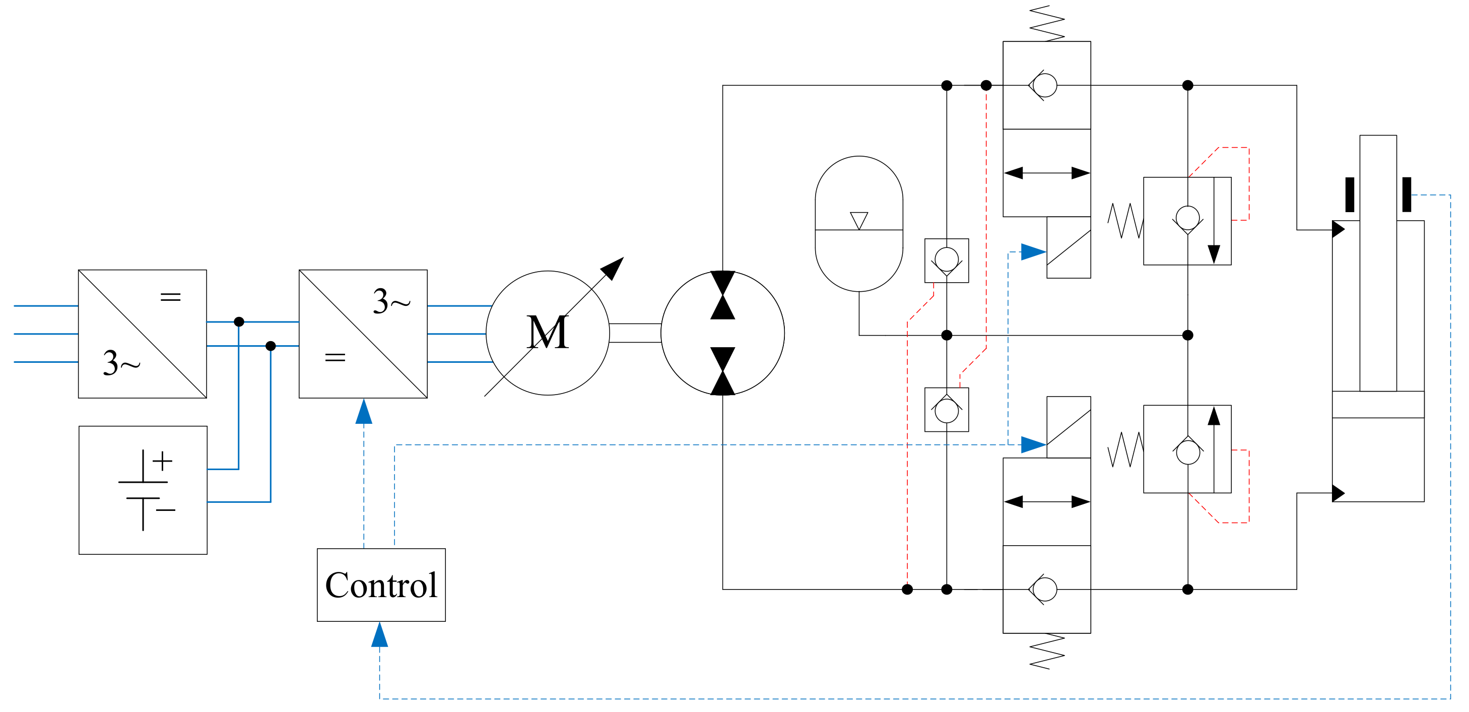
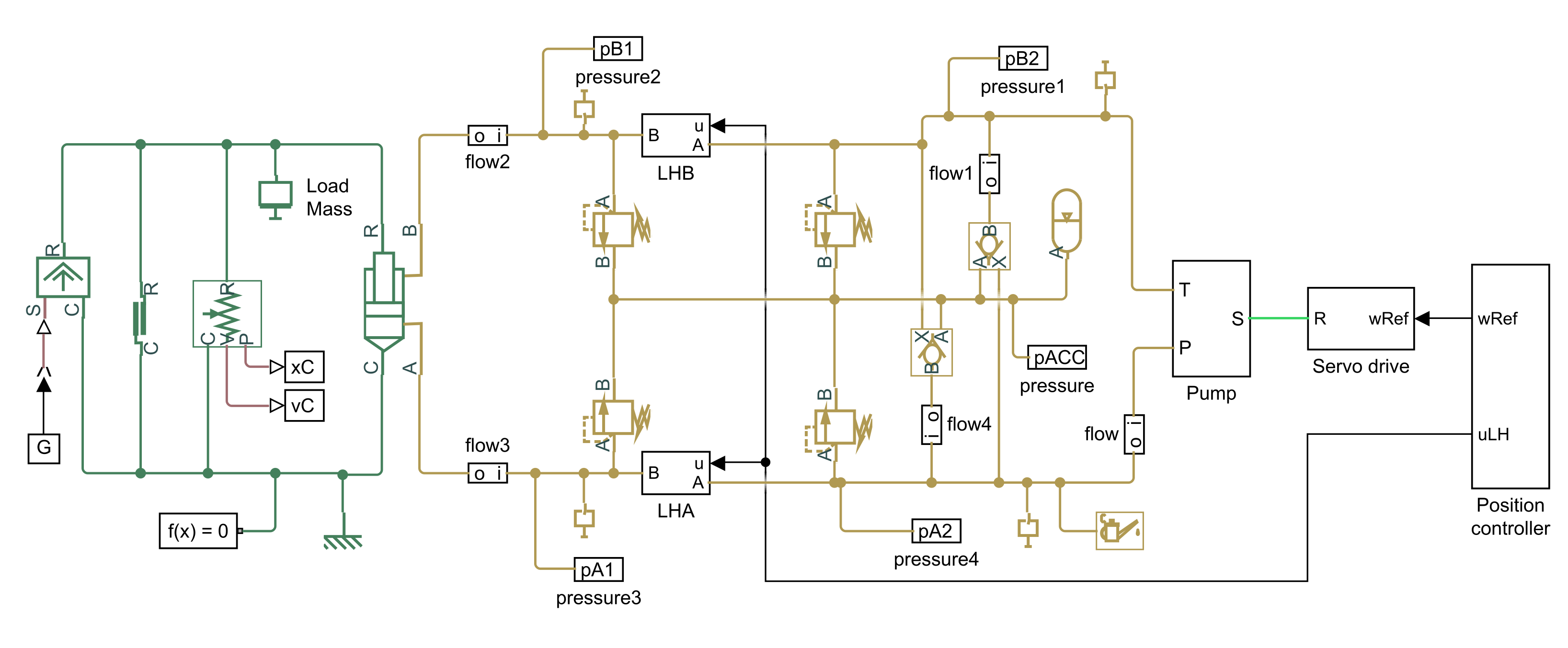
The hydraulic circuit of the EHA contains 2/2 poppet valves for load holding, relief valves for overload handling, accumulator and POCVs for differential flow compensation, and a bidirectional pump connected to a servomotor for four-quadrant operation. The proposed novel concept is shown in Figure 1.
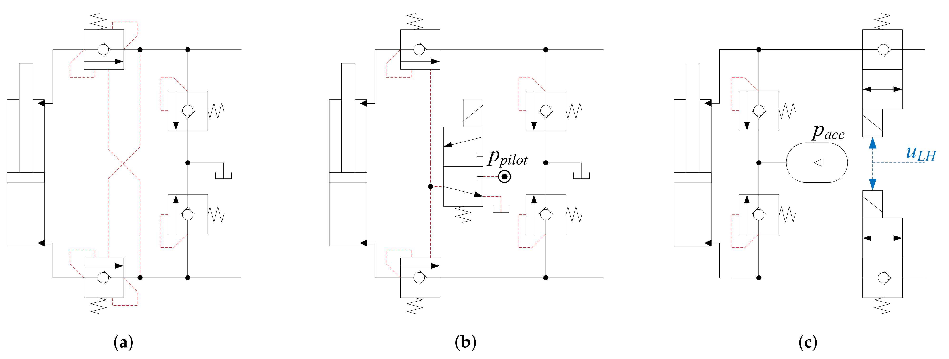
Using electrically actuated 2/2 poppet valves for passive load holding allows for regenerative braking when they are opened. Typically, counterbalance valves are used and offer load holding and safe handling of overrunning loads. However, when operating the system with assistive loads in quadrants 2 and 4, they function as hydraulic brakes and dissipate the excess energy as heat. In addition, they require moderate pressure on the opposing line to open. By design, they cannot be used with regenerative braking systems. Another approach is to use an external pilot pressure to force the valve fully open when the system needs to move the load. This way the system retains the passive load holding and overload handling and is, in theory, capable of regenerating energy. The disadvantage is the requirement of an external pilot pressure of typically 50–150 bar, which may require an additional small pump when used in an EHA since the servomotor does not idle when no motion is needed. Illustrations of topologies for load holding and overload handling are shown in Figure 2.
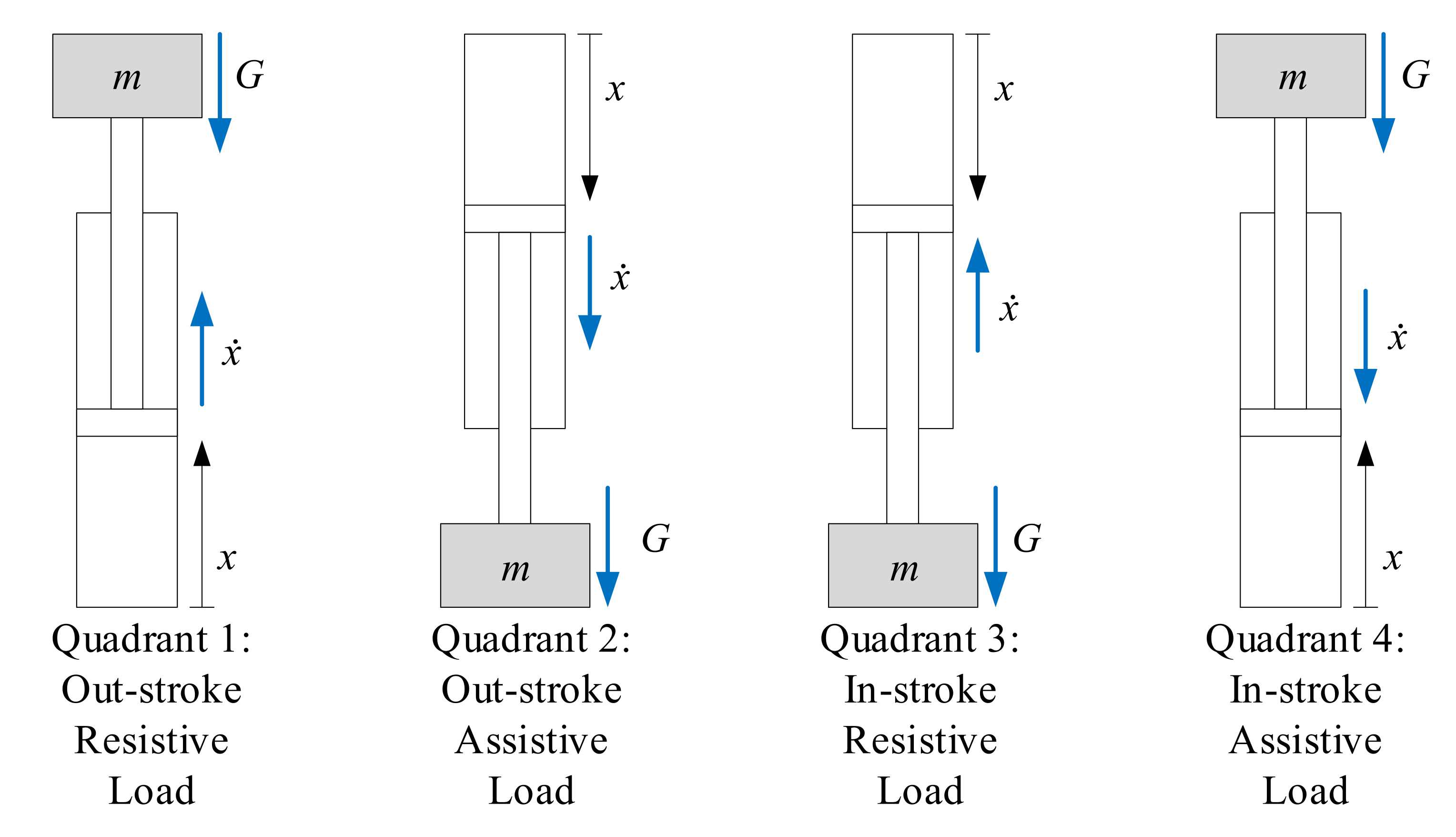
Four-quadrant operation is a crucial requirement for the EHA. An illustration of the load force, cylinder velocity, and hydraulic flows for each quadrant is shown in Figure 3. Red lines and blue lines denote high pressure and low pressure, respectively. The accumulator is always connected to the low pressure, and the flow in and out of the POCVs change depending on the quadrant.
3. Considered System
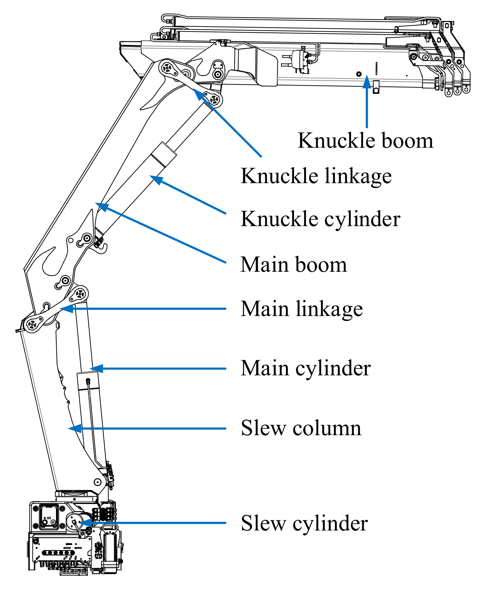
In this paper an HMF 2020K4 loader crane has been used as a basis for the detailed design and simulation of the EHA, shown in Figure 4. The novel concept is investigated by applying it to two degrees of freedom on a hydraulic loader crane; the main cylinder and the knuckle cylinder. Hence, components and control parameters are quantified and the concept is evaluated via time-domain simulations. The simulations are performed using an outer path control loop with anti-swing which have been developed earlier in [27,28]. The novel concept has also been compared with a traditional design with a single pump driven by an induction motor and proportional valves to control each actuator. The cylinder data are shown in Table 2.
4. Electro-Hydrostatic Actuator Design
The prime mover of the EHA is a servomotor which is driving a fixed displacement pump. The motor is connected to a servo drive modeled as a self-contained unit similar to commercial products and consists of a DC-bus, inverter, current controller, and speed controller.
4.1. Electric Servo System
The servomotor and controller are modeled in the -frame, using the Park transformation , defined in Equations (1) and (2).
where
- = d-axis voltage;
- = q-axis voltage;
- = a-phase voltage;
- = b-phase voltage;
- = c-phase voltage;
- = electrical rotor angle;
- = stator resistance;
- = d-axis inductance;
- = q-axis inductance;
- = number of pole pairs;
- = motor speed;
- = permanent magnet flux linkage;
- T = rotor torque;
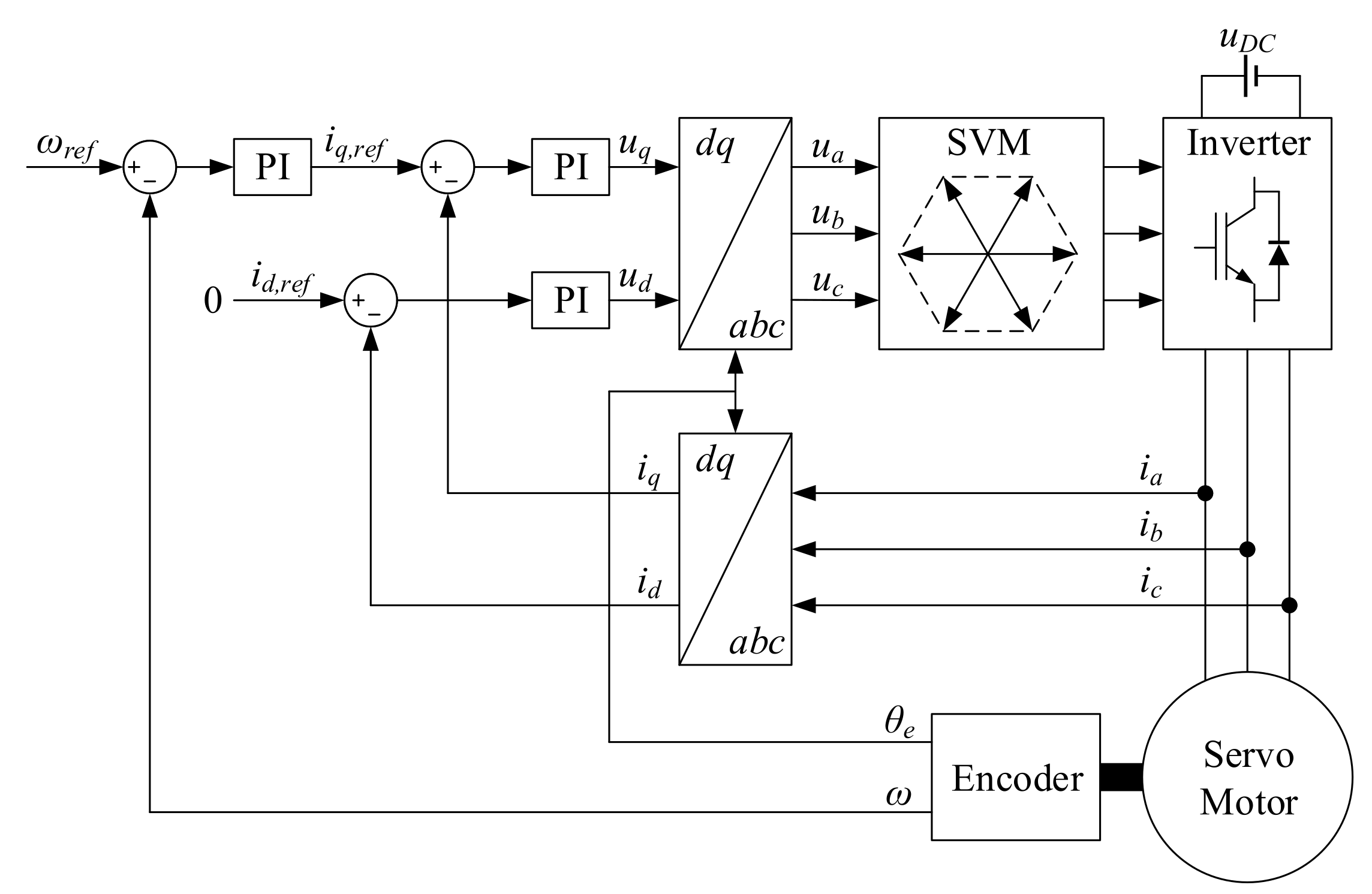
The controller uses Field Oriented Control (FOC) and operates in the -frame, shown in Figure 5. It uses the motor currents, rotor speed, and electrical rotor angle as feedback. The inner current PI-controller regulates the q-axis current to generate the required torque, while the d-axis current reference is kept at zero since the motor is not operated in the field weakening range. The outer speed PI-controller takes a speed reference as input from the user. Space vector modulation (SVM) is used to generate the signals to the inverter. Parameters for the controller are given in Table 3.
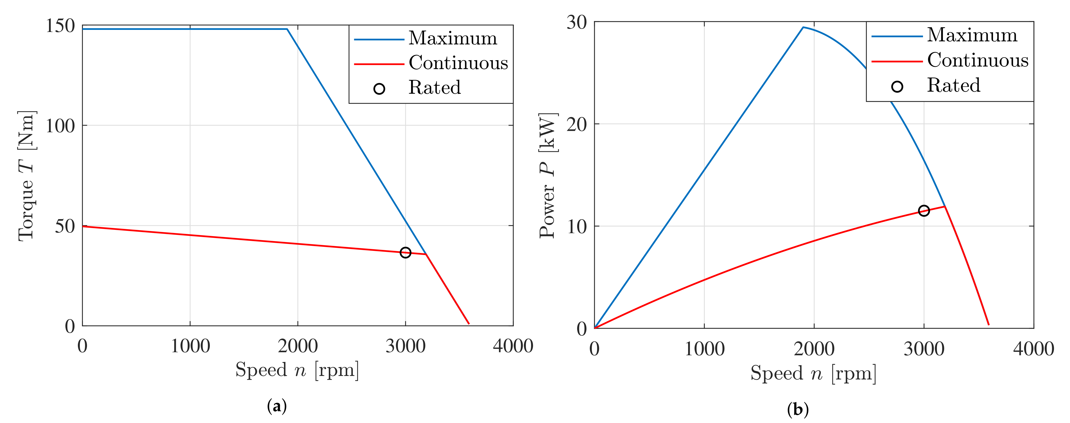
The selected servomotor is a Beckhoff AM8064R, with its data shown in Table 4. The characteristic curves of speed-torque and speed-power are shown in Figure 6. Based on the maximum speed-torque curve shown in Figure 6a and the torque constant , a torque limiter is made inside the speed PI-controller by limiting the current reference using the measured motor speed.
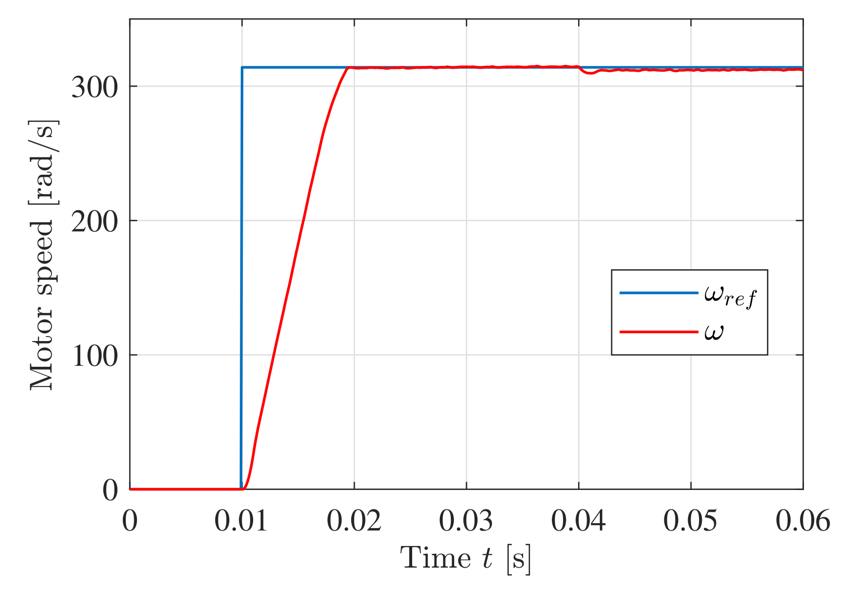
The closed loop response of the servomotor and servo drive using FOC is shown in Figure 7. It shows excellent performance with a low rise time, no overshoot at the speed step, and minimal undershoot at the load step.
4.2. Hydraulic System
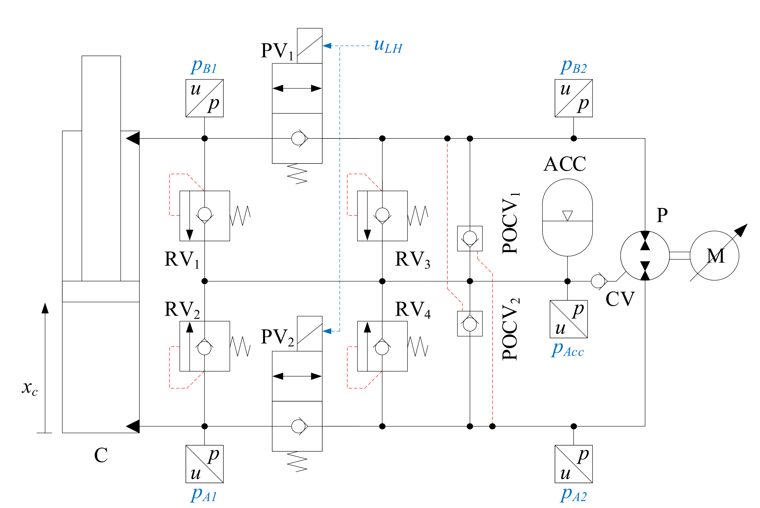
For this system a pressure level of 300 bar and a required flow of 40 L/min is selected yielding a peak power of 20 kW. The detailed design of the hydraulic circuit with, pump, valves, and pressure sensors is shown in Figure 8. The valve sizes can be chosen based on the selected pressure level and the rated flow of each valve, given in the datasheet. Optional oversizing to reduce the pressure drop may also improve system efficiency. The selected components are listed in Table 5.
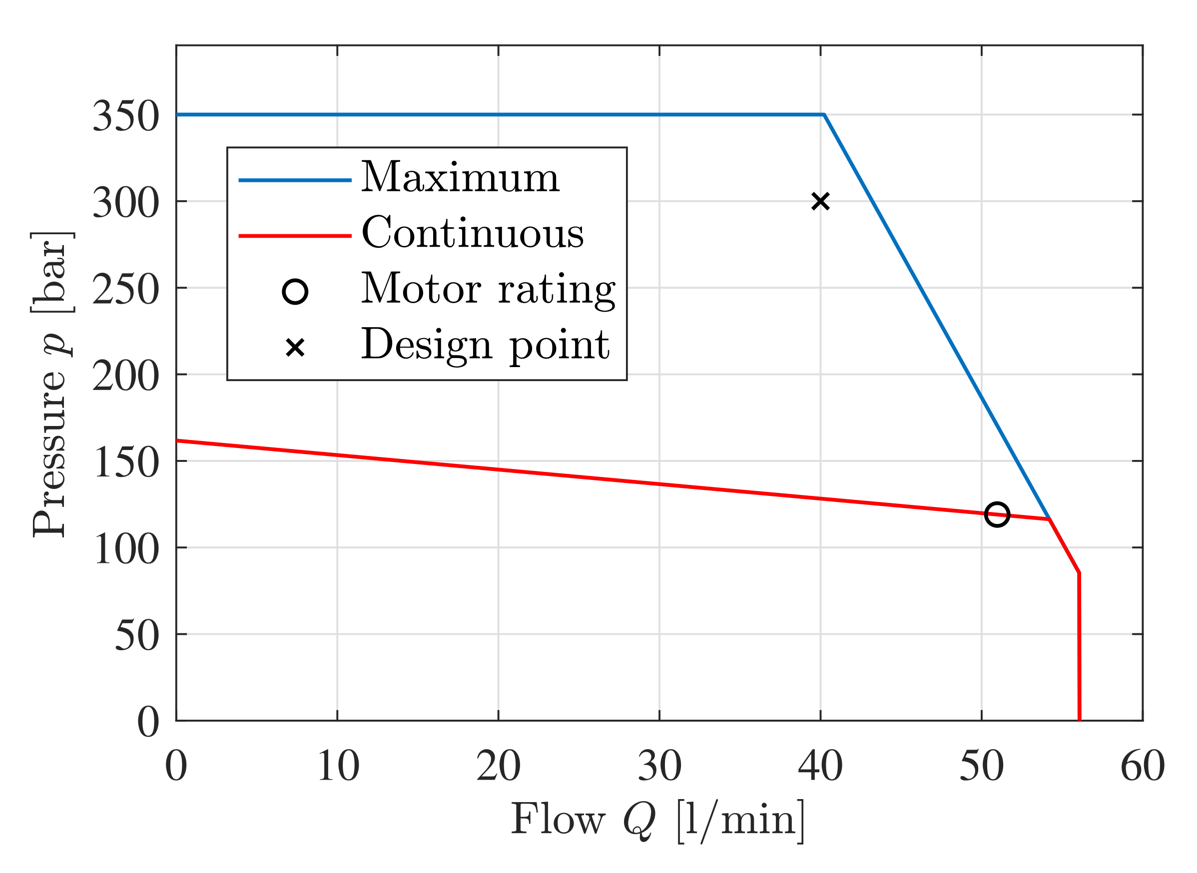
Selecting the pump displacement in a traditional system primarily depends on the required flow if a standard constant speed induction motor is used. On the other hand servomotors are inherently variable speed devices and are typically offered with rated speeds from approximately 500 rpm to 10,000 rpm. Design considerations for the pump and motor include the selected pressure level, required flow, peak power, and maximum pump speed. For a given pump-motor combination a flow-pressure curve can be made showing the operating region of the system. This is shown for the selected pump and motor in Figure 9. The maximum pump speed and maximum pump pressure limits the operating region compared to the speed-torque curve shown in Figure 6a. Note that the design point is closer to the maximum rating than the continuous rating, as the servomotor is not expected to run continuously when used for position control.
Sufficient information for the hydraulic pump was not available in the datasheet, therefore the pump is modeled with the same efficiencies at nominal operating conditions as the pump in Section 7, with a volumetric, hydraulic-mechanical, and total efficiency at nominal operating conditions of , , and . This yields a leakage coefficient of l/min/bar and viscous damping coefficient of Nms/rad.
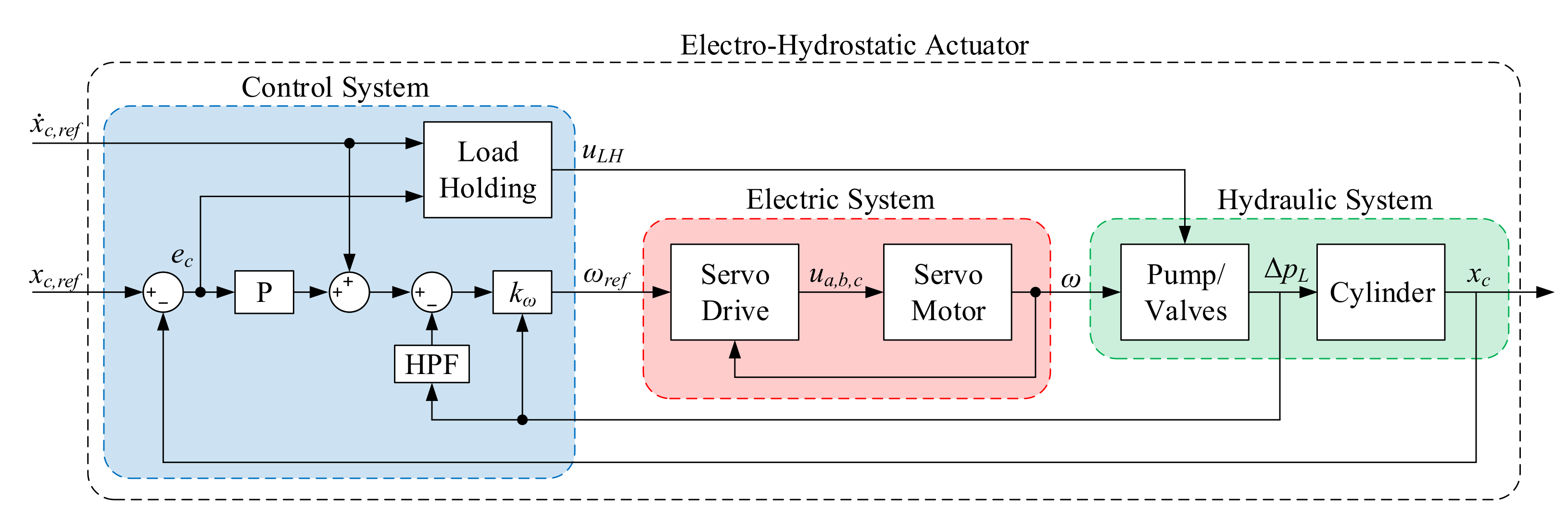
4.3. Control System for EHA
The control system for the EHA is shown in Figure 10 and is a feedback proportional position controller that utilizes a velocity feedforward line. The constant is the ratio from cylinder velocity to motor speed, defined in Equation (7). It depends on the load pressure difference , cylinder areas and , and pump displacement D. In addition, pressure feedback is used based on the load pressure difference, which is going into a high pass filter, shown in Equation (8). This is to dampen oscillations in the cylinder motion. The EHA controller sends the motor speed reference to the servo drive.
The load holding signal which opens the 2/2 poppet valves is defined in Equation (10). It is based on the cylinder position error and cylinder velocity reference .
5. Numerical Analysis of Four Quadrant Operation
A numerical analysis is conducted with the system connected to a constant load mass. The load mass m is 30,000 kg, and the accumulator pre-charge gauge pressure is 5 bar. The cylinder is moving the mass vertically. The force acting on the cylinder can be considered to consist of three parts; the hydraulic force, the gravitational force, and the friction force. The friction force is modeled with the viscous friction coefficient and Coulomb friction force as a function of the cylinder velocity . The parameter is used to smooth the friction around zero velocity. The forces in quadrant 1 is shown in Equations (11) and (12). An illustration of the cylinder velocity and load mass in four quadrants is shown in Figure 11. The simulation model from MATLAB/Simulink is shown in Figure 12.
5.1. Tuning of Controller Parameters
The pressure feedback bandwidth should be less than the minimum eigenfrequency of the hydraulic system . This is to avoid filtering out the motion of interest. The minimum eigenfrequency is calculated based on the minimum hydraulic stiffness , given below for a differential cylinder:
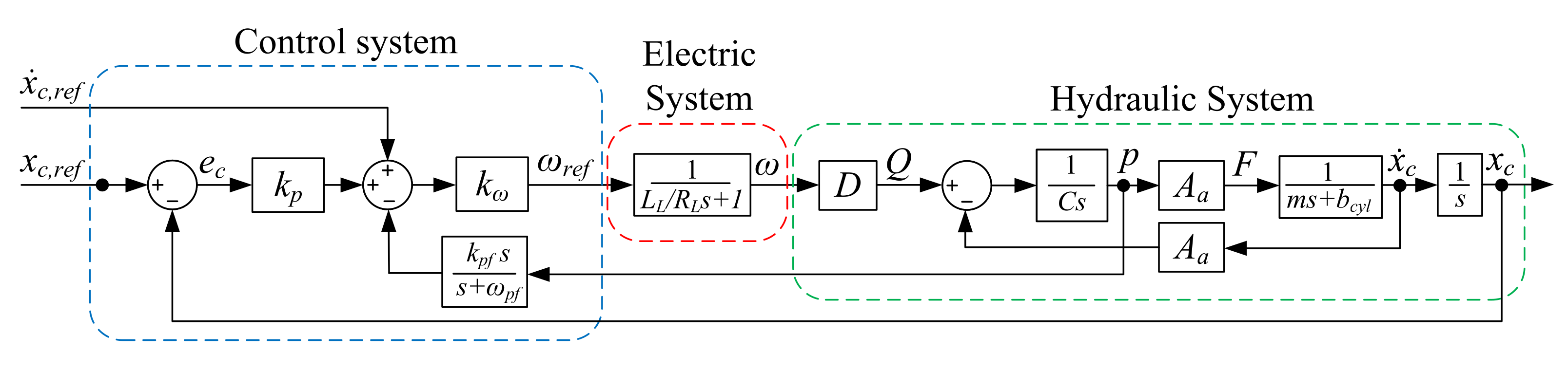
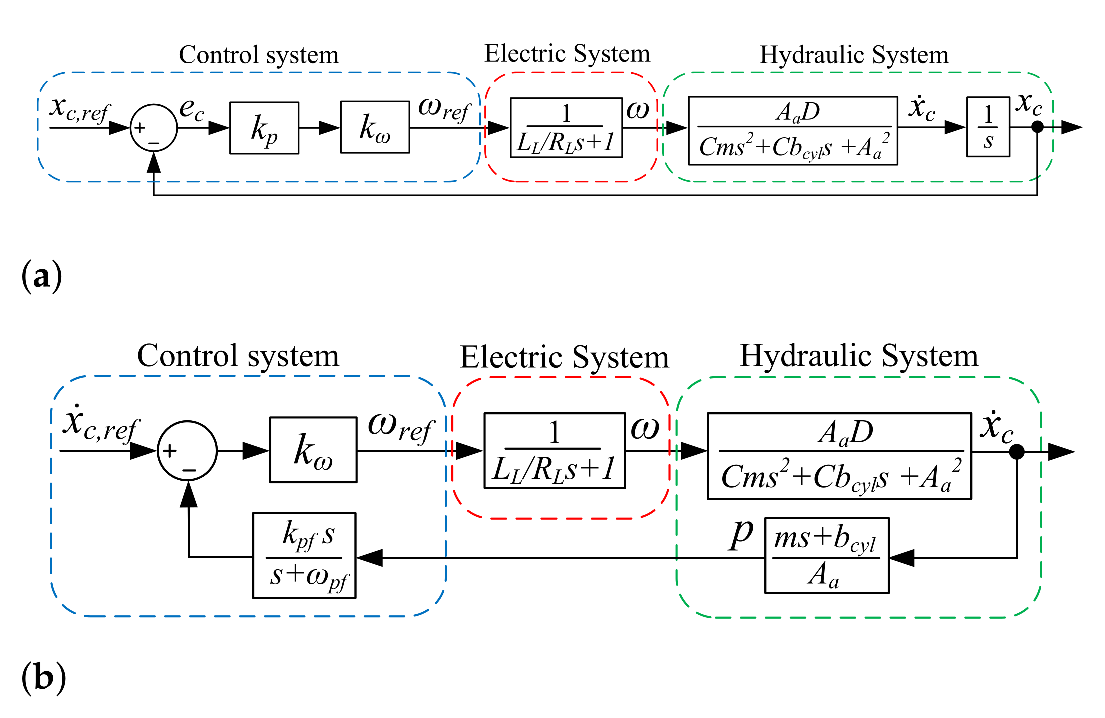
For the cylinder in the Simscape model the minimum eigenfrequency is rad/s, and the pressure feedback bandwidth is set one decade below at rad/s. The control parameters and can easily be tuned manually or iteratively using the nonlinear Simscape model to achieve a balance between setpoint tracking and minimal oscillations. Another approach is to linearize the system and tune the controllers using linear control theory. A few assumptions and simplifications are made. Firstly, the load holding valves are ignored, meaning the pump is pushing fluid directly into the cylinder. The system is assumed to operate in Quadrant 1 meaning there is a high pressure on the piston-side of the cylinder and a low pressure on the rod-side, set to bar. The cylinder is also assumed to be fully extended, . A block diagram of the linearized model is shown in Figure 13.
The electric system could in theory be linearized as a DC-equivalent motor with the servo drive containing PI-controllers for the motor current and motor speed. However, simplifications can be made where the transfer function from speed reference to motor speed has a time constant which approximates to the motor time constant . This assumes that the motor and drive are properly configured as a closed-loop system. The selected motor has a time constant of 9.7 ms, and it can be seen from the closed loop response in Figure 7 that this approximation is a good fit. A similar approach was also used in [15]. The linearized parameters used in the model are the hydraulic capacitance C, and viscous damping for the cylinder and motor, given in Equations (15)–(17). A nominal cylinder speed of m/s is used, and Pa is used for the bulk modulus of the hydraulic oil.
Tuning of the two parameters and can be done separately by rearranging the transfer functions for the control system, electric system, and hydraulic system, shown in Figure 14.
Tuning these two models are straightforward, and can be done using for example bode plots, step responses, or MATLABs PID Tuner. The feedback gain should provide fast setpoint tracking without excessive oscillations, and the pressure feedback gain should dampen the oscillations without slowing the system down. The step responses are shown in Figure 15.
5.2. Simulation Results From Simscape Model
While the linearized models can provide some insight to appropriate controller parameters, the non-linear Simscape model is used to verify the performance of the EHA and its control system. The controller parameters have been selected based on both the linear and nonlinear model. The friction parameters have been estimated from the HMF 2020K4 crane in the laboratory. Simulation parameters are shown in Table 6.
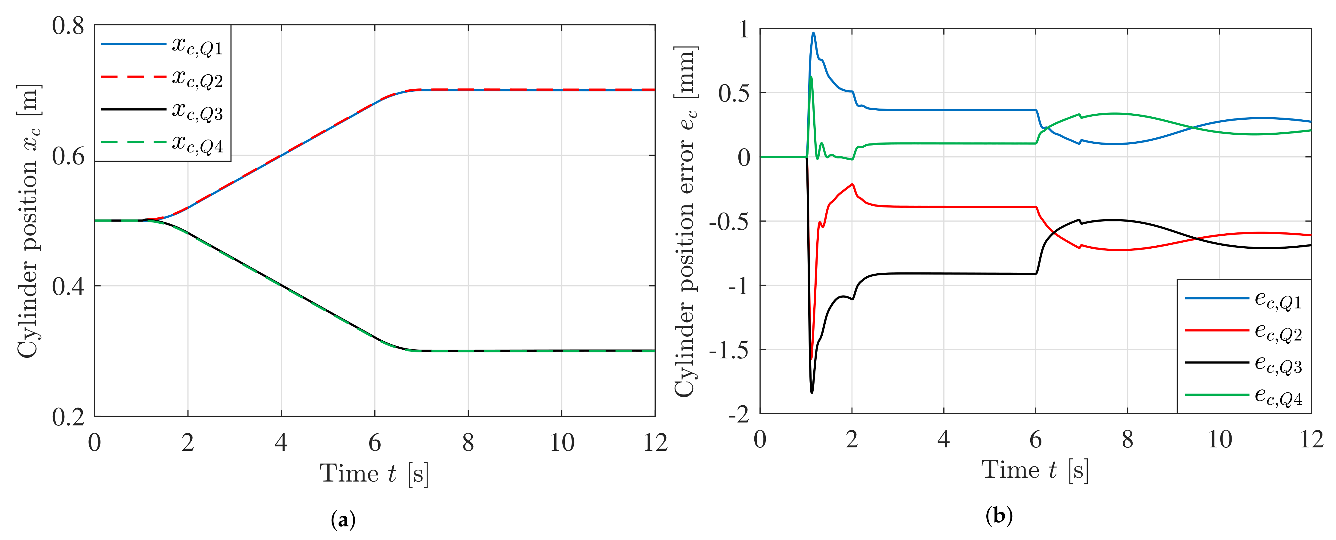
Position and position error during the simulation are shown in Figure 16. The system shows excellent position tracking in all four quadrants. The cylinder is following a trapezoidal velocity profile from 0.5 m and traveling 0.2 m.
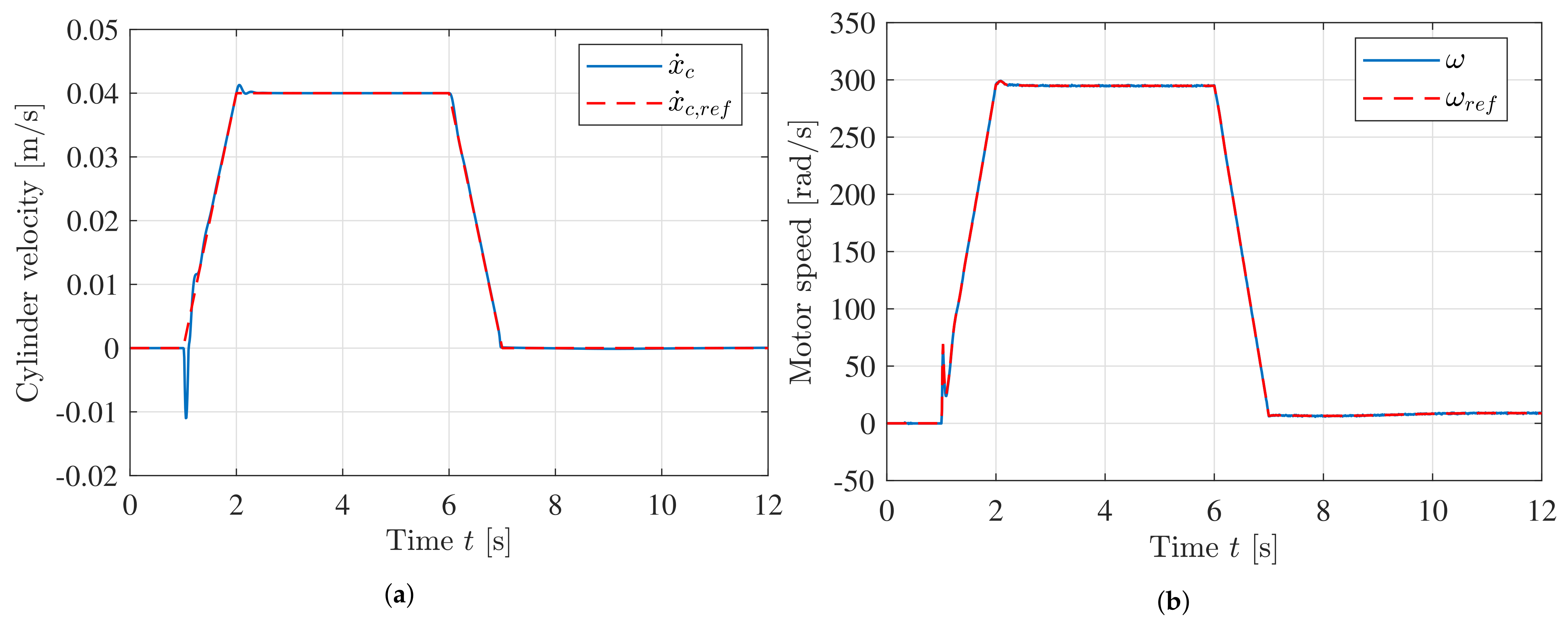
The cylinder velocity and motor speed are shown in Figure 17. The cylinder velocity reference is a trapezoid, while the motor speed reference is generated by the EHA controller. Both the cylinder and the motor follow the reference during motion with minimal overshoot.
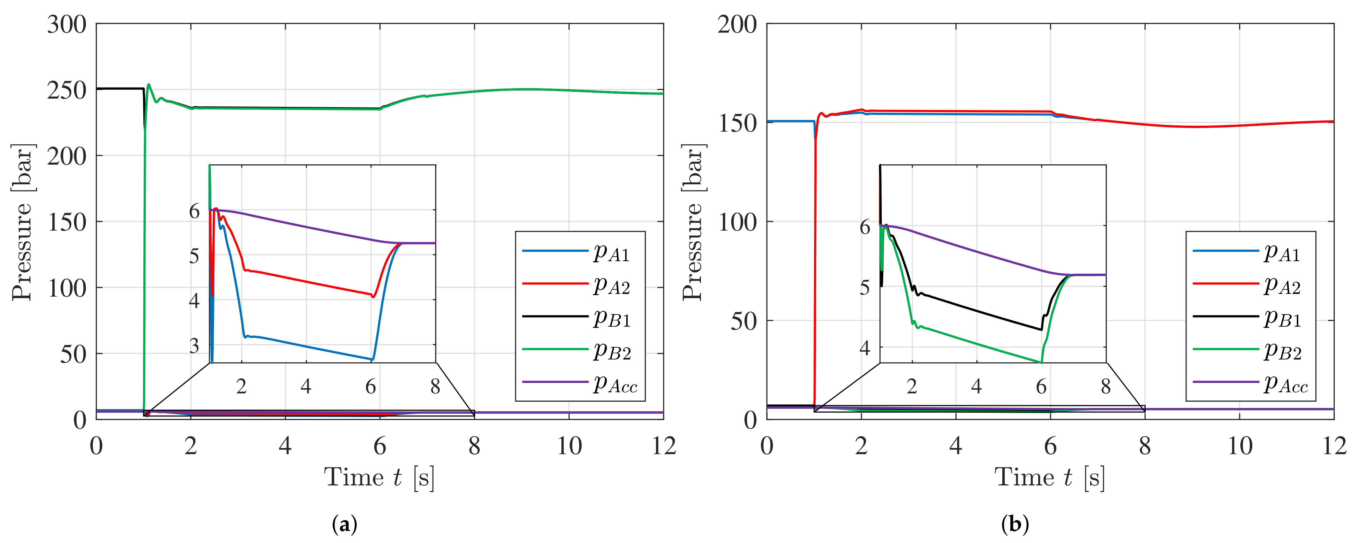
Plots of the system pressures are shown in Figure 18. The pressures are not oscillating, showcasing stability during motion. The cylinder pressures are higher in quadrant 2 and 3 since the gravitational force is acting on the smaller rod-side area. The system pressures are lowest in quadrant 2, but the system is not experiencing cavitation.
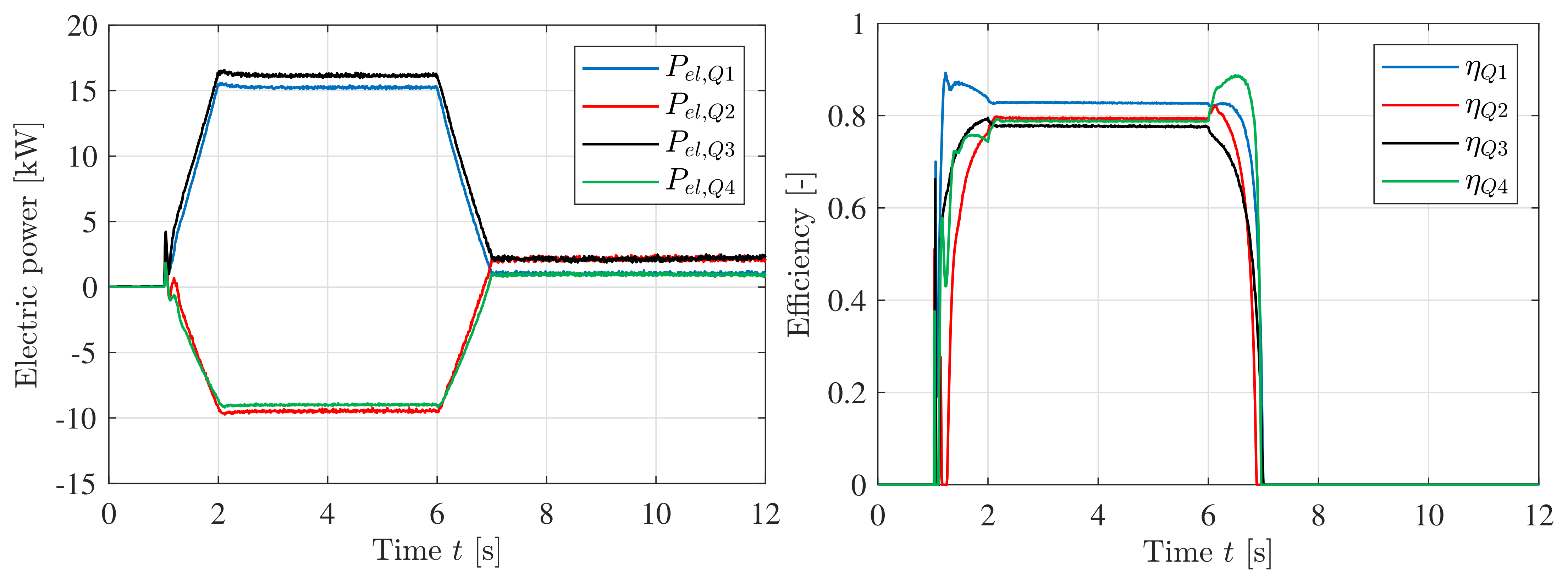
The system efficiency is of significant interest for the EHA. To calculate the efficiency of the system, the power coming from/going into the DC-bus, accumulator, and cylinder must be considered. While the contribution from the accumulator is rather small, depending on the quadrant, the accumulator can receive or deliver power to either the cylinder or back to the DC-bus. The system consumes approximately 15 kW when pumping, and delivers approximately 10 kW when motoring. The efficiency during motion is between 0.78 and 0.85, shown in Figure 19.
6. Thermal Considerations
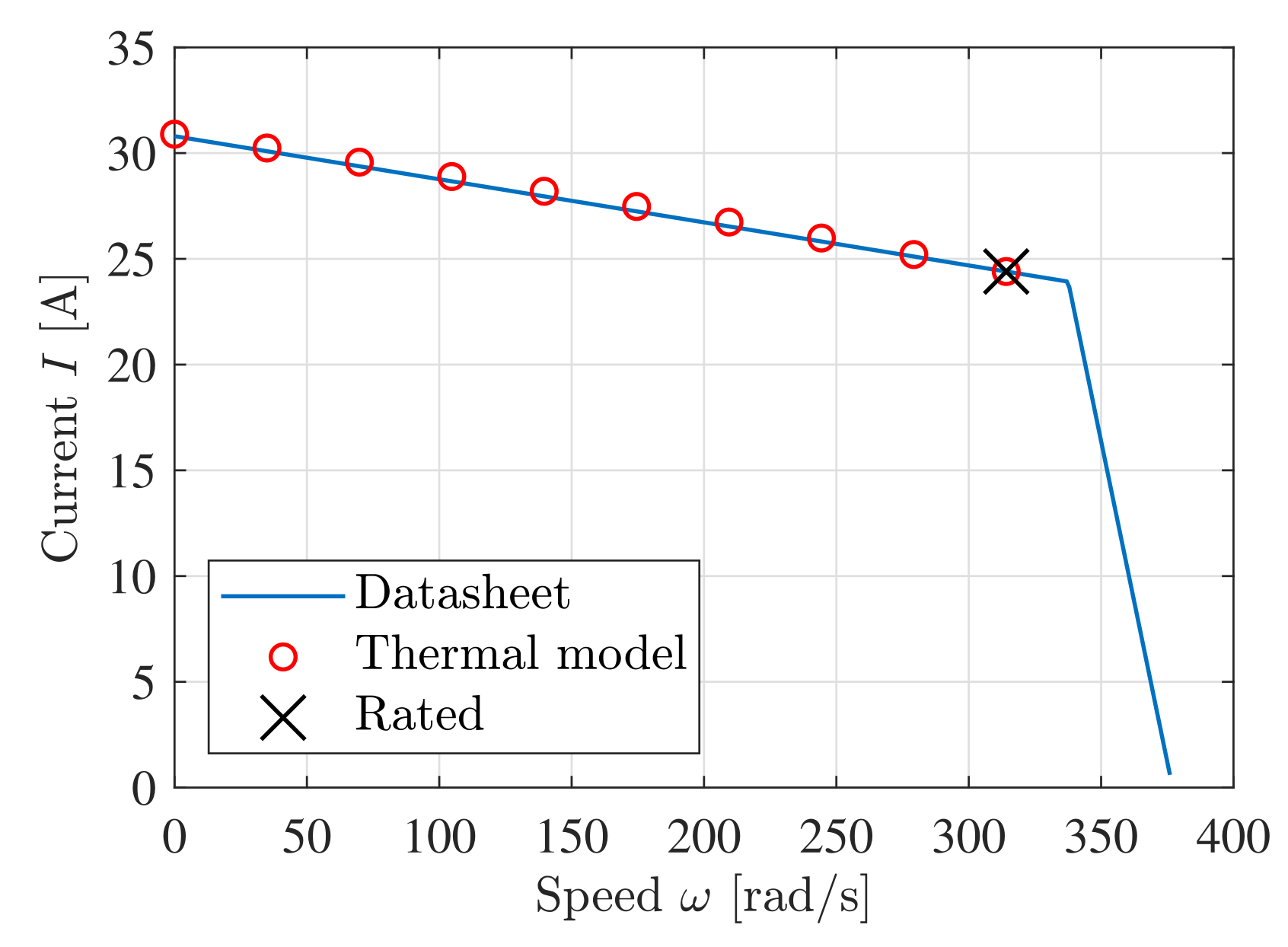
To model the thermal behavior of the servomotor a first order transfer function is used. The input is the power dissipated in the motor and the output is the motor temperature above ambient. The thermal time constant min is given in Table 4 and the steady state gain can be calculated from rated operation. The motor is rated thermal class F which allows a temperature rise of 105 C above ambient. The calculations are shown in Equations (18)–(20). Figure 20 shows the allowable continuous current to stay below 105 C as a function of the motor speed . The thermal model is very close to the data interpolated from the datasheet.
To simulate the dynamic thermal behavior of the motor a load cycle similar to the one used in Section 5 is used. The system operates in quadrant 1 and 4. The motor current and motor speed are then passed into the thermal model which runs this load cycle for 5 h. The system is tested with different payloads to analyze the temperature response. Plots of the load cycle and temperature are shown in Figure 21. These results show that the system is able to operate indefinitely with the load mass used in Section 5 of 30,000 kg (30 Ton).
7. Valve-Controlled System
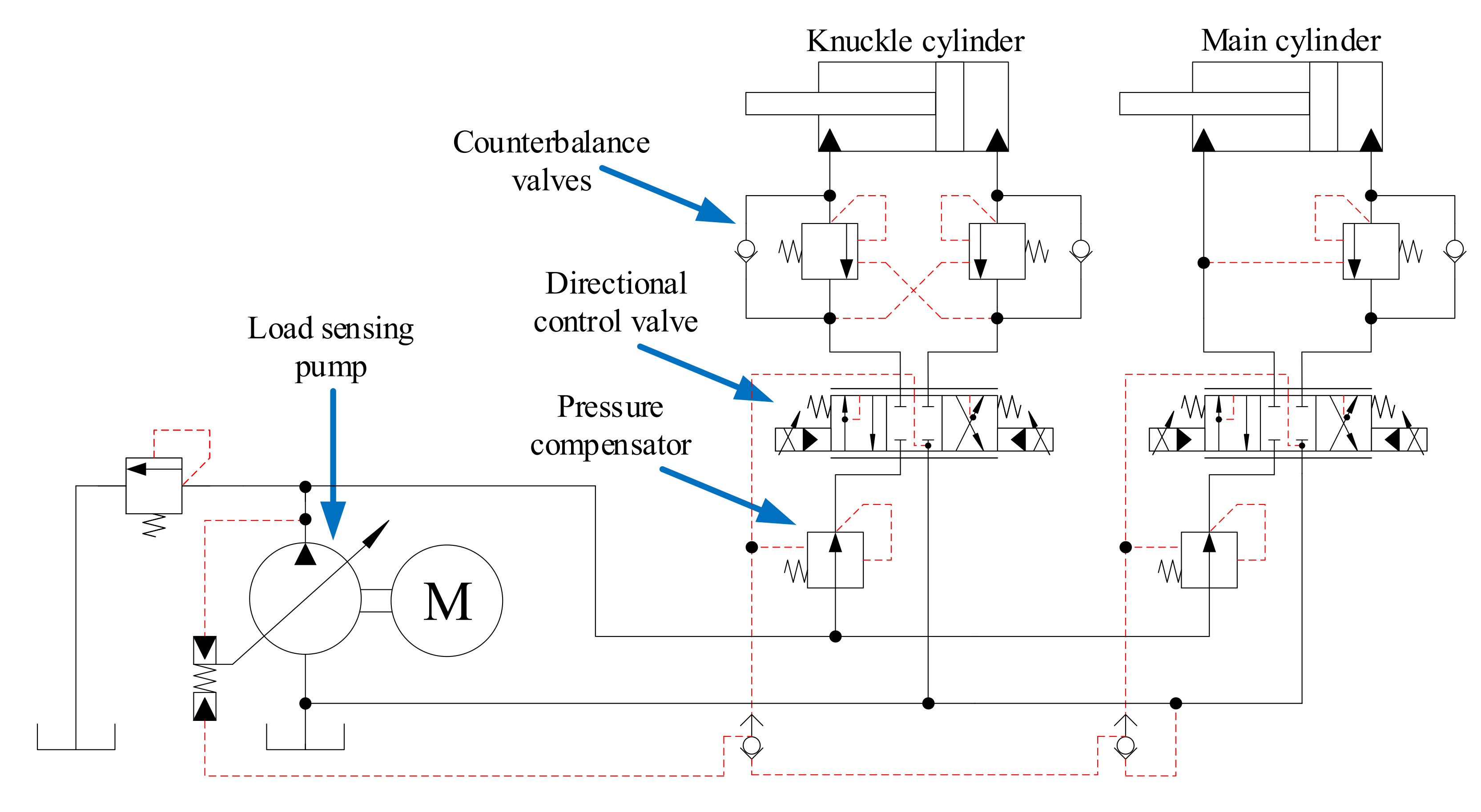
In the valve-controlled system the two cylinders are driven by a single variable displacement load sensing pump. A pressure compensator, directional control valve, and counterbalance valves control the motion of each cylinder. This is a state-of-the-art load sensing design which is commonly used in industrial applications such as offshore hydraulic cranes, as well as the HMF 2020K4 crane in the laboratory. An illustration of the hydraulic circuit is shown in Figure 22.
The pressure compensator throttles the flow to ensure that there is a constant pressure drop over the directional control valve. This in turn gives a load independent flow. The governing equations of the pressure compensator in steady state are given in Equations (21) and (22).
where
- = compensated pressure at port p;
- = pressure at port a;
- = pressure at port b;
- = spring pressure setting;
- = load pressure;
- = position of the main spool, ;
Double counterbalance valves are used on the knuckle cylinder, and throttle the flow to assist in load holding and load lowering. The unitless openings of the counterbalance valves are calculated in Equations (23) and (24).
where
- = opening of valve a, ;
- = opening of valve b, ;
- = pressure at valve a input side;
- = pressure at valve a actuator side;
- = pressure at valve b input side;
- = pressure at valve b actuator side;
- = crack pressure of valve a;
- = crack pressure of valve b;
- = pilot area ratio;
- = pressure difference for full opening;
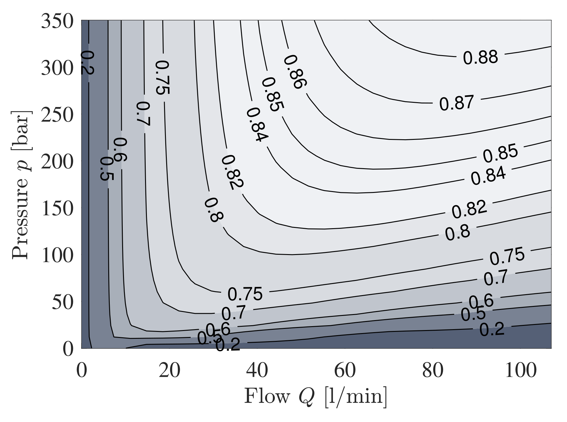
The pump is a Bosch Rexroth A4VSO with a displacement of 71 cm/rev. The datasheet for the pump yields a laminar leakage model, with a leakage coefficient of L/min/bar. The friction model has been interpolated to be viscous friction with a damping coefficient of Nms/rad. This gives a volumetric, hydraulic-mechanical, and total efficiency at nominal operating conditions of , , and , respectively. Based on the estimated parameters a contour plot of the pump total efficiency as a function of pressure and flow is shown in Figure 23, showing poor efficiency when operating with either low flow or low pressure.
During operation the pump pressure and pump flow are functions of the load sensing pressures and actuator flows, given in Equations (25) and (26). A margin pressure is added to the pump pressure setting. This is to ensure the pressure compensator has some headroom to adjust the pressure drop over the directional control valve. A consequence of this margin pressure is the poor efficiency seen when the load pressures are low. The margin pressure typically ranges from 10 bar to 30 bar, and bar is used in this simulation.
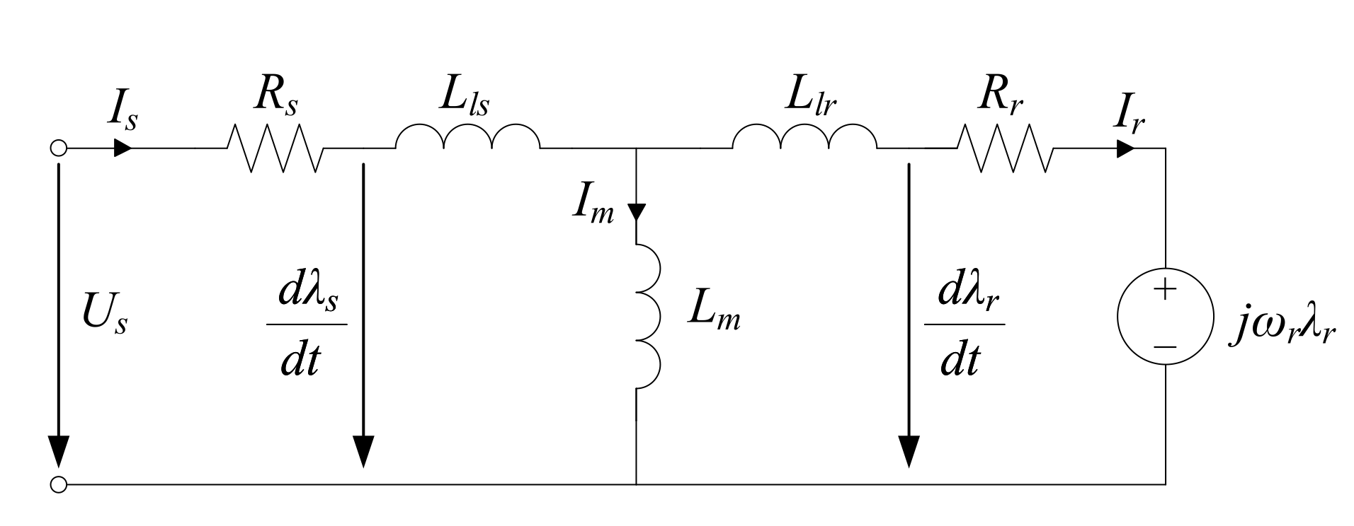
The hydraulic pump is driven by a constant speed induction motor. The motor is selected to be an IE3 4-pole 30 kW induction motor from ABB [29]. The motor data given in the datasheet is shown in Table 7, and the dynamic motor model is shown in Figure 24.
The motor parameters have been estimated based on the motor data with the following estimations and assumptions:
- Leakage inductances and are 5% of the magnetizing inductance . The nominal stator flux , magnetizing current , and inductances and can then be calculated as
- Stator conduction losses contribute to 40 % of the losses. The stator resistance is then calculated as
- Rotor conduction losses contribute to 40 % of the losses. The rotor current and rotor resistance are calculated as
- The last 20 % of the losses are modeled as Coulomb friction losses. The friction torque is calculated as
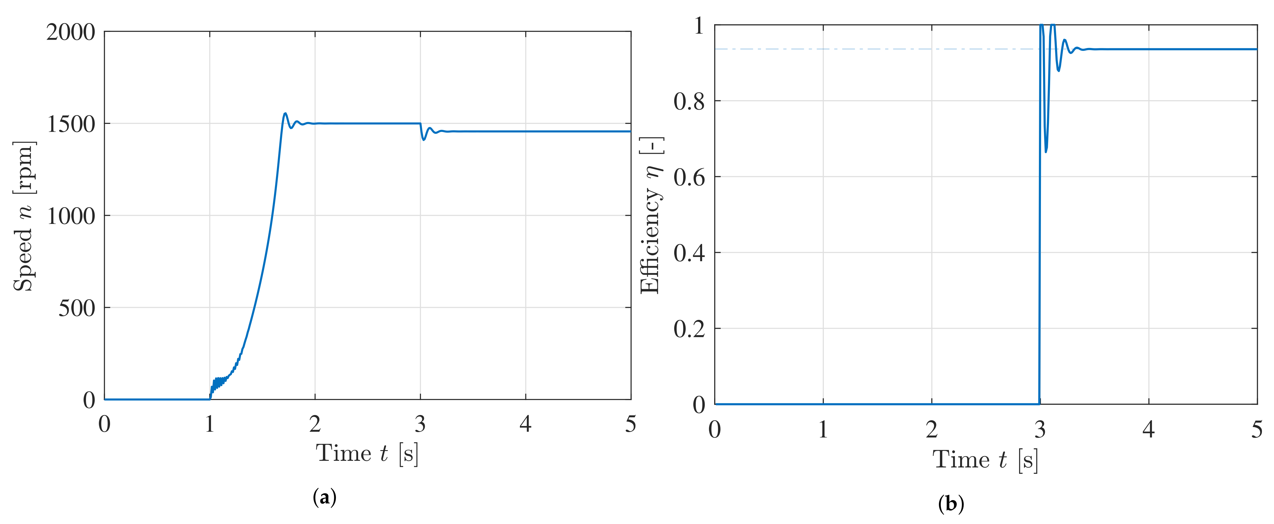
As the efficiency of the motor model is crucial to determine the efficiency of the system, a numerical simulation with constant load is used as verification. The dynamic response and efficiency of the motor is shown in Figure 25, with startup at 1 second, and full load at 3 s. The efficiency of the motor matches the motor data, shown with a dash-dotted line.
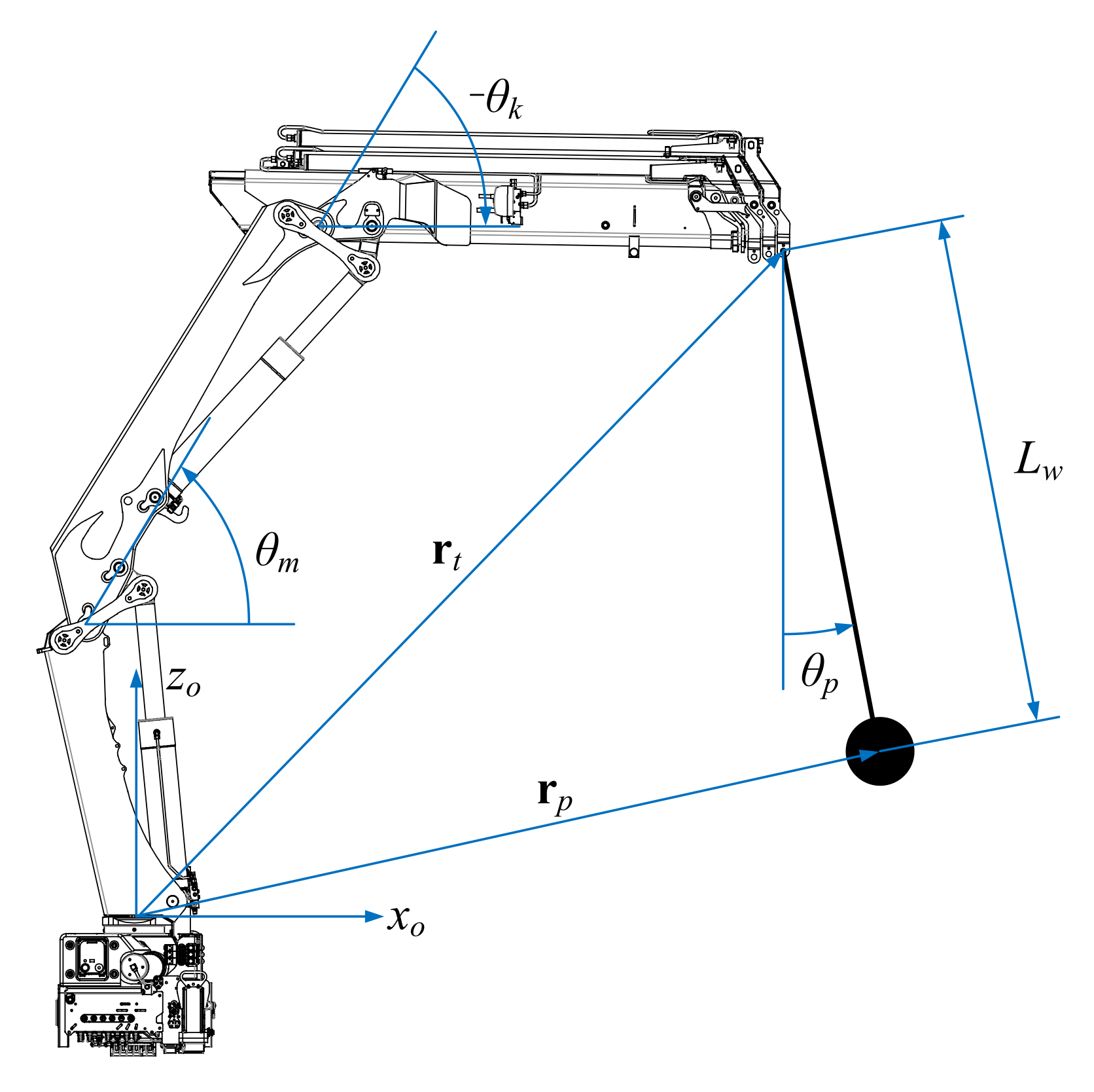
8. Load Case: Path Control and Anti-Swing for Hydraulic Crane
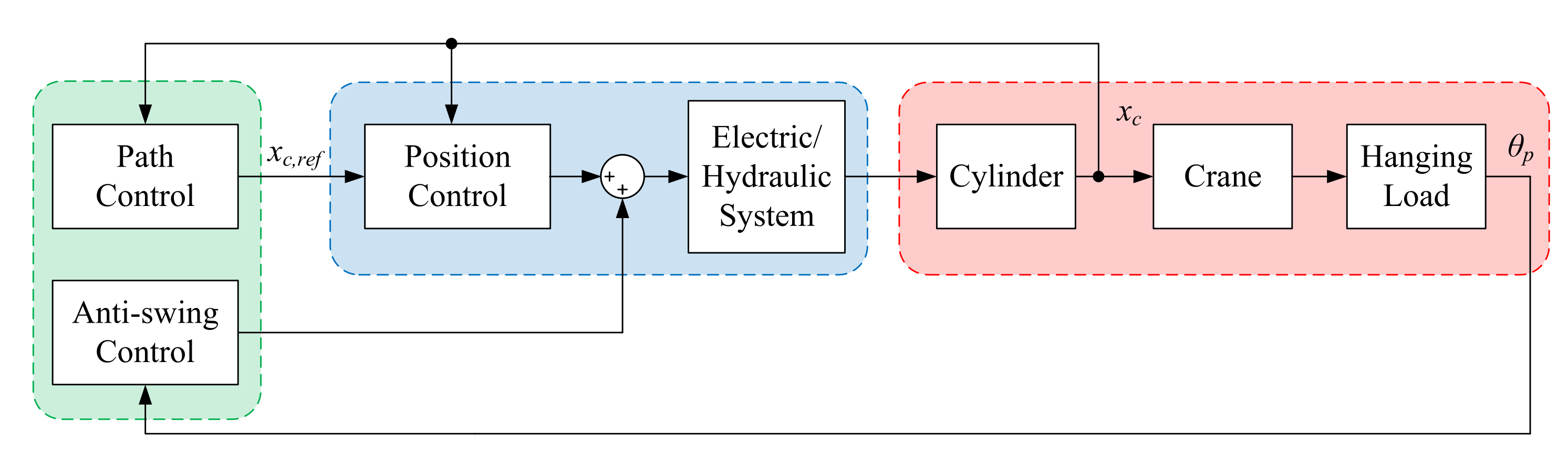
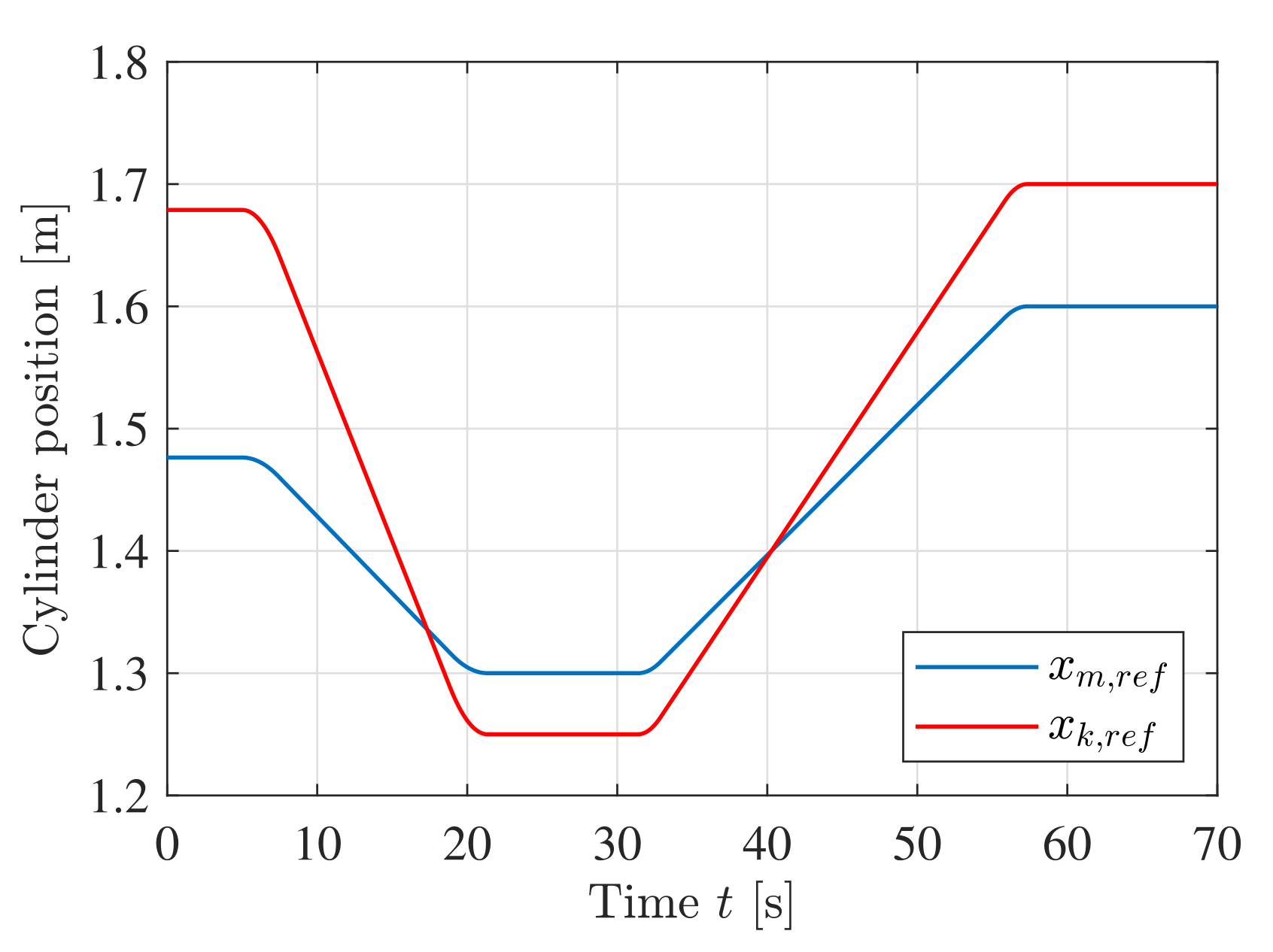
To test the performance of the developed system, numerical simulations are carried out with path control and anti-swing as a load case. Path control and 2-DOF anti-swing have previously been developed in [27,28]. An illustration of the HMF 2020K4 crane with hanging load is shown in Figure 26. A block diagram of the path control, anti-swing control, and the crane is shown in Figure 27. The green blocks have been developed earlier, the red blocks represents the mechanical system, and the blue blocks represents either the valve-controlled system or the EHA developed in this paper. The cylinder position reference used in the path controller is shown in Figure 28. The path is designed such that the knuckle cylinder operates in all four quadrants during motion. Two simulations are carried out running the same path, one with a traditional valve-controlled system, and one with the new EHA.
8.1. Simulation with Valve-Controlled Actuators
The first test is the original valve-controlled system running path control and 2D anti-swing. Compare energy efficiency etc. The simulation is carried out with the same controller parameters used in [28].
Plots of the pump pressure and pump flow are shown in Figure 29. At s the system is changing between quadrants seen as a change in the load sensing pressure.
A plot of the power and consumed energy is shown in Figure 30. During motion 46 kJ was delivered to the cylinders while 505 kJ was consumed from the grid. This yields an overall efficiency of less than 0.1.
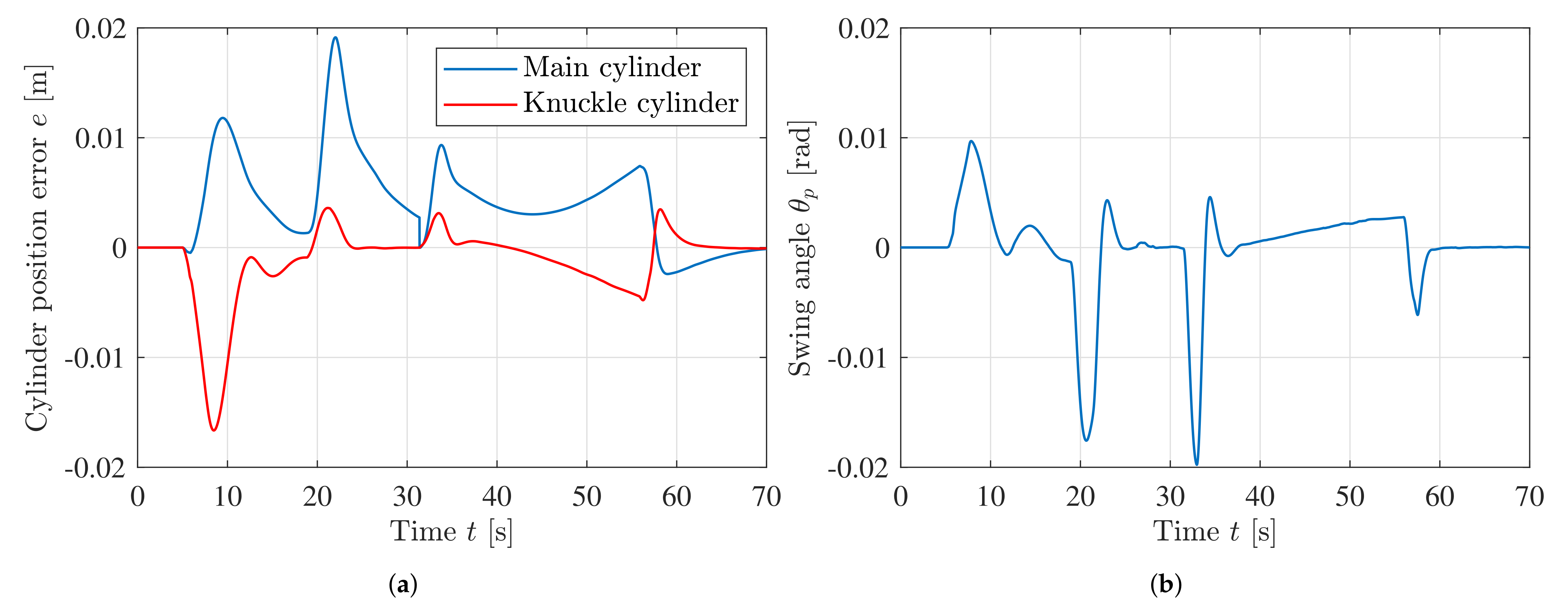
The cylinder position error and swing angle are shown in Figure 31 to evaluate the performance of the control system. The RMS value of the position errors and swing angle are calculated to be RMS() = 5.8 mm, RMS() = 3.6 mm, and RMS() = 4.3 mrad.
8.2. Simulation with Electro-Hydrostatic Actuators
The second test is when two separate EHAs are mounted on the HMF 2020K4 and running path control and 2D anti-swing.
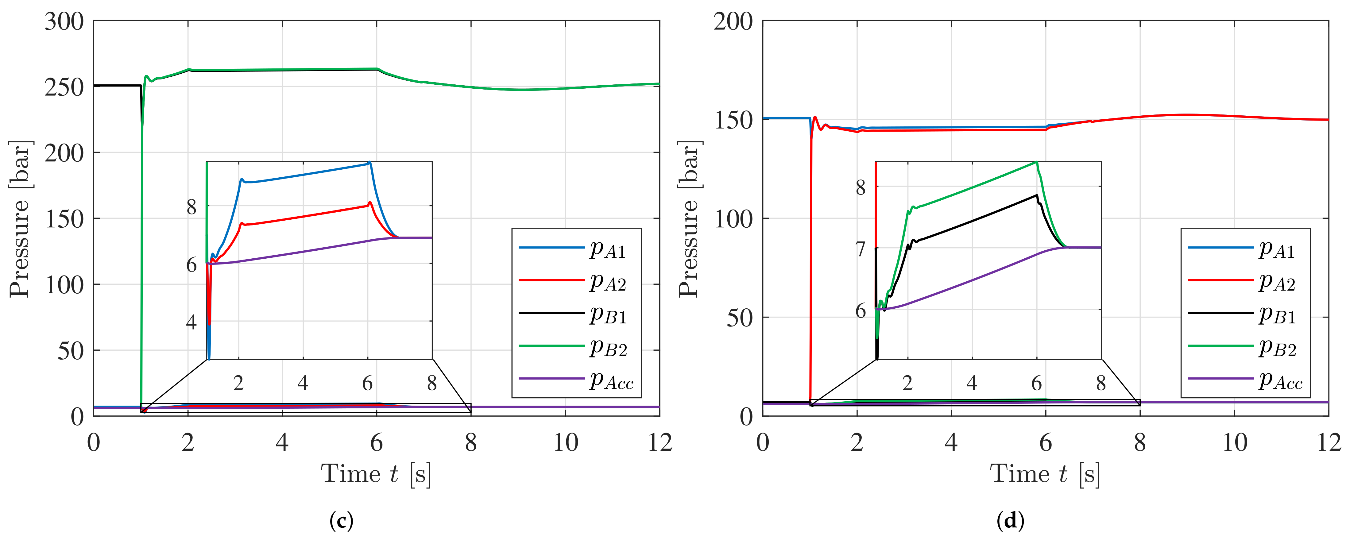
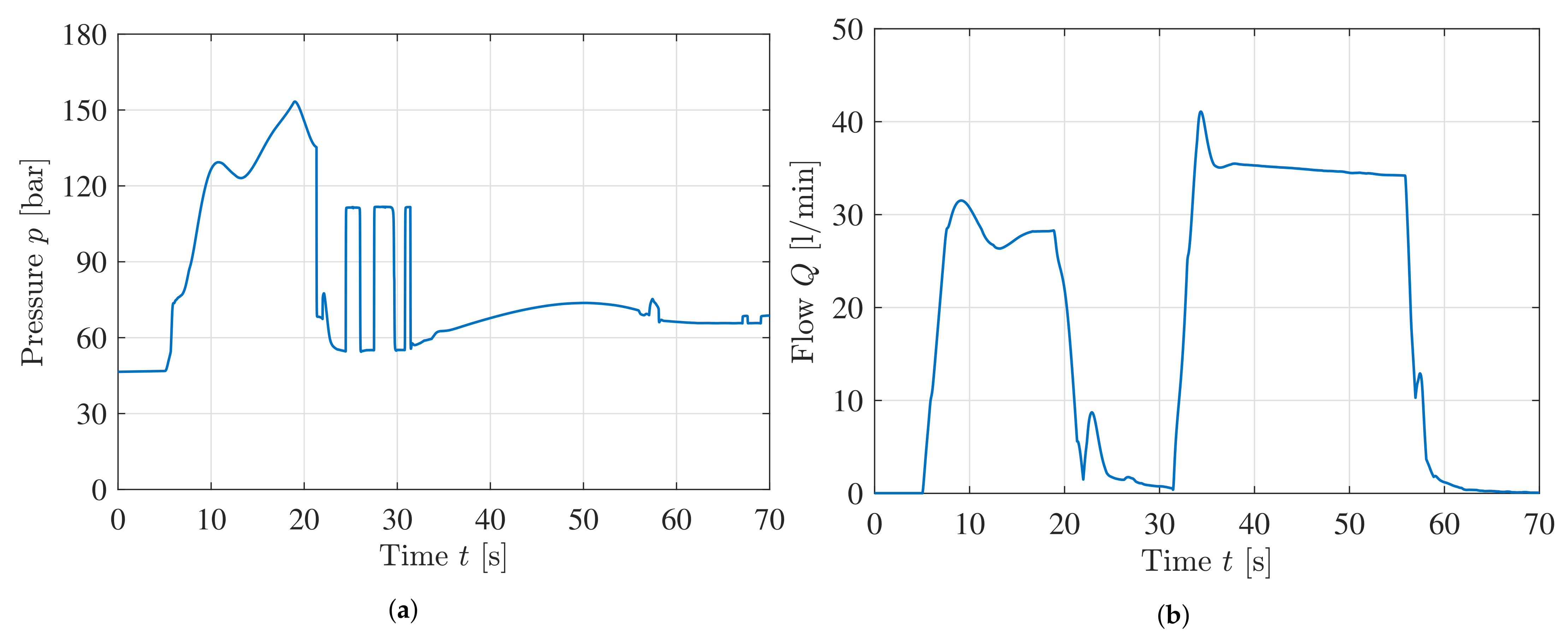
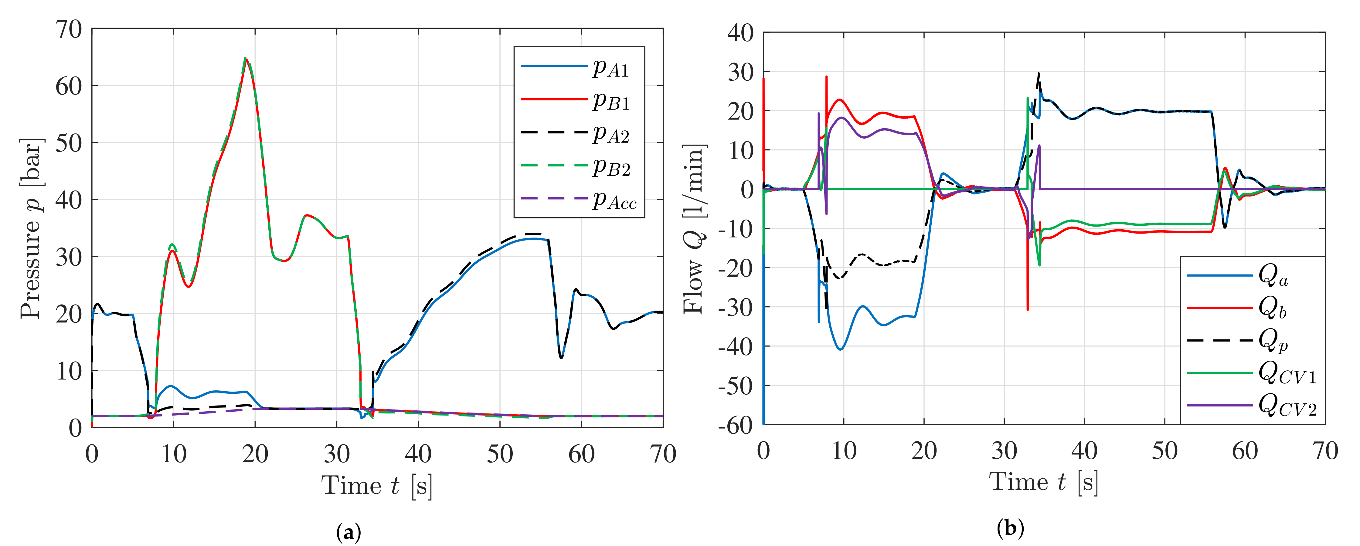
Plots of the pressures and flows in the knuckle circuit are shown in Figure 32. Some oscillations can be seen as the system compensates for the swing angle during motion.
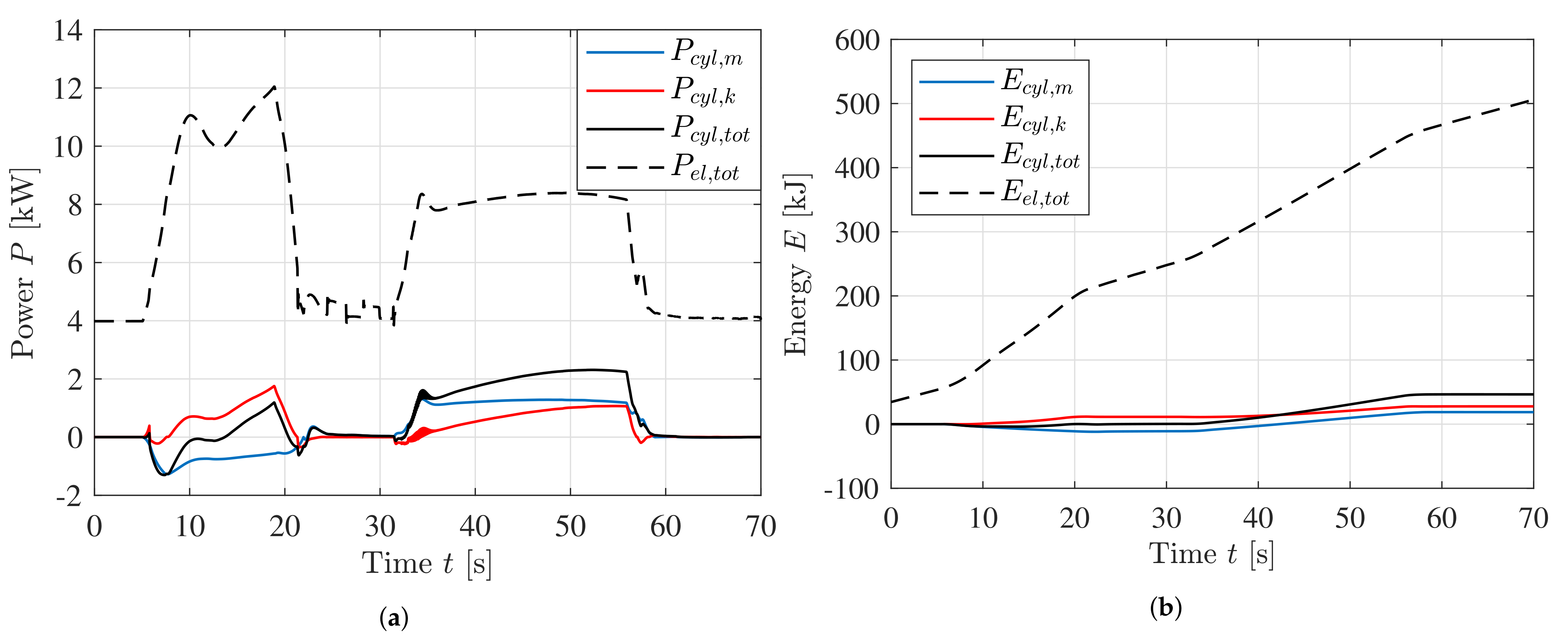
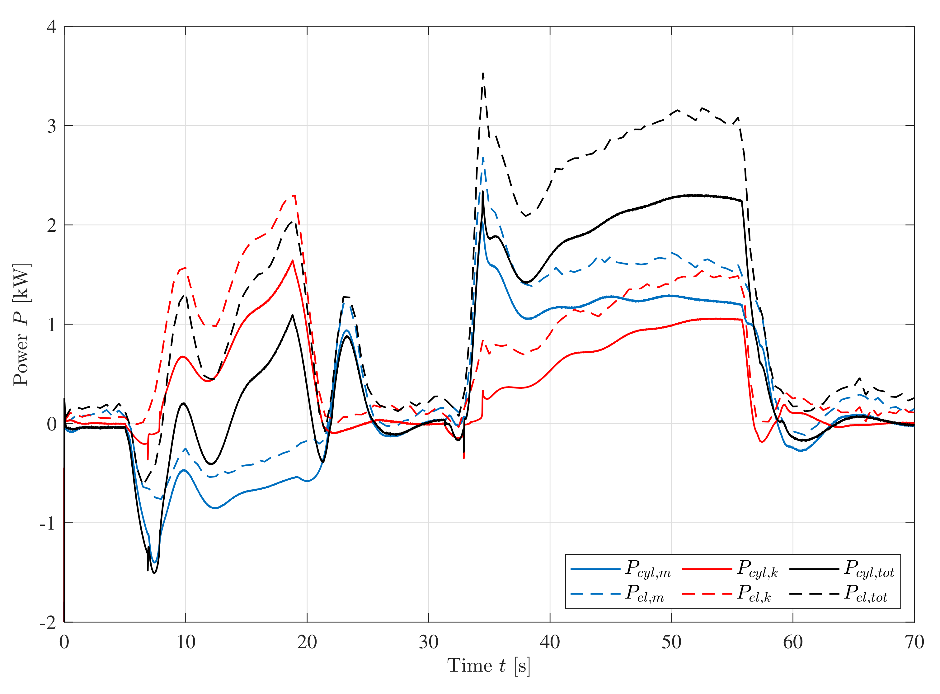
A plot of the electric power from the grid and the power to the cylinders is shown in Figure 33. Negative power indicate that the system is regenerating power. The total power is the sum of the main EHA and knuckle EHA.
A plot of the consumed energy is shown in Figure 34. After completing the motion 47 kJ was delivered to the cylinders while 88 kJ was consumed from the grid.
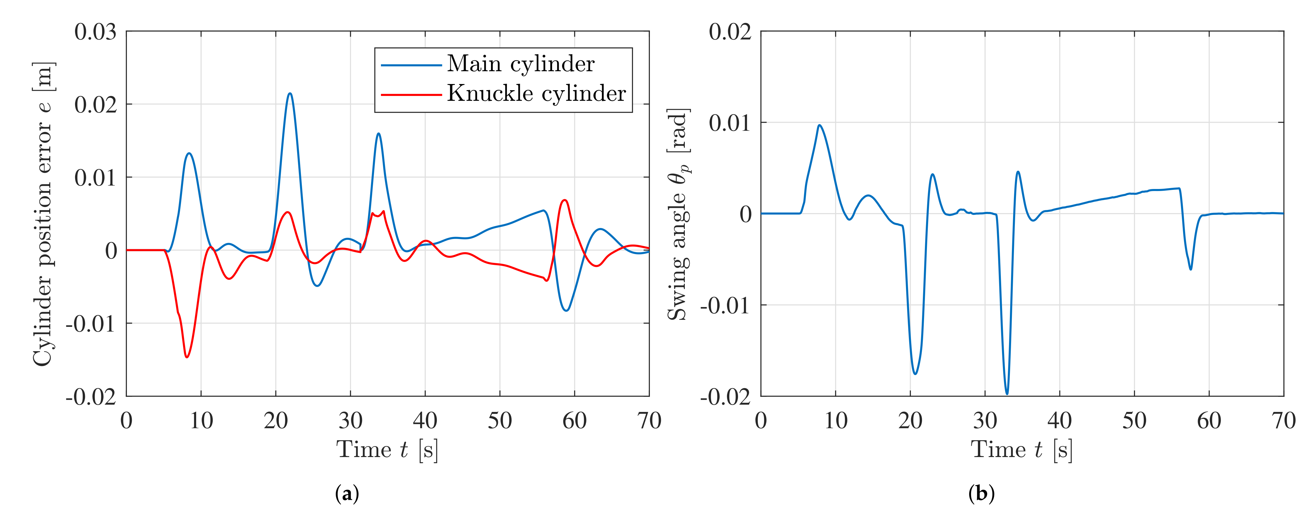
Cylinder position error and swing angle are shown in Figure 35 to verify the performance of the novel concept. The RMS value of the position errors and swing angle are calculated to be RMS() = 5.4 mm, RMS() = 3.3 mm, and RMS() = 4.4 mrad, virtually identical to the valve-controlled system.
9. Discussion
There are many advantages to EHAs, but also some disadvantages which will be discussed in this chapter. Today the use of EHAs allows for self-contained hydraulic systems, typically with electric power cables coming from a centrally located servo drive. The use of EHAs will often reduce the number of hydraulic hoses in a system, minimizing the risk and environmental impact of spilling hydraulic fluids in case of hose rupture. While EHAs require a battery pack or capacitor bank to effectively store the regenerated energy, traditional valve-controlled systems often require cooling to handle the generated heat from the hydraulic system. While not exclusive to EHAs, the use of one servomotor per actuator eliminates the problem of flow sharing typically found in valve-controlled systems, meaning each actuator can run at full power at all times. This also eliminates the problem of flow and pressure mismatch in load sensing hydraulic systems, where the pump must deliver a high pressure to all actuators even if only a single actuator has a high load pressure.
By using the high fidelity models in Simscape the EHA is tested under various loading conditions. The system is able to lift the payload of 30,000 kg with good position tracking and high efficiency. Even though the design point of the system is above the rated conditions, a thermal analysis shows that the system is able to operate indefinitely using the prescribed position reference. This is due to the inherently low duty cycle of position control for the servo system.
During the load case with anti-swing the performance of the valve-controlled system and the EHA are almost identical. The main difference is the energy consumption which is greatly reduced by using the novel system, shown in Table 8.
These results equate to a reduction in energy consumption of 82%, and an increase in overall efficiency from 9% to 53%. This showcases the excellent energy efficiency of the novel EHA. The reduced energy consumption is closely related to the ability to regenerate electrical power. The higher initial cost of the EHA, especially for the servomotor, servo drive, and battery pack, will be offset by the greatly reduced energy consumption.
10. Conclusions
This paper investigates electro-hydrostatic actuators applicable to large multi-axis hydraulic manipulators. The novel system is designed and analyzed to comply with requirements such as load holding, overload handling, and differential flow compensation. The electric servo system is modeled in the -frame and uses Field Oriented Control to regulate the motor current and motor speed. The hydraulic system has been designed and modeled using commercially available components and includes 2/2 poppet valves for load holding and pilot-operated check valves for differential flow compensation. The control system uses feedforward control for cylinder velocity and feedback for cylinder position, in addition to pressure feedback to reduce oscillations. Control logic for energizing the load holding valves is also presented.
A numerical analysis of four quadrant operation with constant load is first conducted. The cylinder follows a trapezoidal velocity profile during motion. The results show good tracking performance for both the servomotor and cylinder, with minimal oscillations. High energy efficiency is achieved in all four quadrants with a peak efficiency of 0.85. These results also showcase the excellent ability to regenerate energy.
A thermal model of the motor is made based on the datasheet, and thermal simulations show that the system can operate indefinitely with a load cycle based on the position reference used in Section 5 and load mass of 30,000 kg.
A load case with path control and anti-swing for a hydraulic crane is conducted to compare the performance and energy efficiency of the novel system with a typical valve-controlled system. A high fidelity model of the valve-controlled system is made to accurately model the energy efficiency in all components. The model consists of a grid-connected induction motor, variable displacement pressure compensated pump, pressure compensated directional control valves, and counterbalance valves. The valve-controlled system and electro-hydrostatic system are actuating two of the cylinders on the crane to follow a prescribed path with a hanging load. Results from the simulations show virtually identical performance regarding the position control of the cylinders and the anti-swing control of the hanging load. The main difference is the significant reduction of energy consumption by 82%, showcasing the superior efficiency of the novel EHA.
Future work may include investigating potential improvements to the design of the EHA, specifically for higher power applications. This may also include building a prototype of the EHA to verify the performance of the system.
Author Contributions
Conceptualization, K.J.J, M.K.E. and M.R.H; methodology, K.J.J; software, K.J.J; validation, K.J.J; formal analysis, K.J.J; investigation, K.J.J; data curation, K.J.J; writing–original draft preparation, K.J.J; writing–review and editing, K.J.J., M.K.E and M.R.H.; visualization, K.J.J.; supervision, M.K.E. and M.R.H. All authors have read and agreed to the published version of the manuscript.
Funding
This research was funded by the Norwegian Ministry of Education and Research grant number 155597. The APC was funded by the University of Agder.
Data Availability Statement
Not applicable.
Conflicts of Interest
The authors declare no conflict of interest.
References
- Bozhko, S.; Hill, C.; Yang, T. More-Electric Aircraft: Systems and Modeling. Wiley: Hoboken, NJ, USA, 2018; pp. 1–31. [Google Scholar] [CrossRef]
- Wheeler, P.; Bozhko, S. The More Electric Aircraft: Technology and challenges. IEEE Electrif. Mag. 2014, 2, 6–12. [Google Scholar] [CrossRef]
- Wang, X.; Liao, R.; Shi, C.; Wang, S. Linear Extended State Observer-Based Motion Synchronization Control for Hybrid Actuation System of More Electric Aircraft. Sensors 2017, 17, 2444. [Google Scholar] [CrossRef] [PubMed] [Green Version]
- Henke, M.; Narjes, G.; Hoffmann, J.; Wohlers, C.; Urbanek, S.; Heister, C.; Steinbrink, J.; Canders, W.R.; Ponick, B. Challenges and Opportunities of Very Light High-Performance Electric Drives for Aviation. Energies 2018, 11, 344. [Google Scholar] [CrossRef] [Green Version]
- Wheeler, P. Technology for the more and all electric aircraft of the future. In Proceedings of the 2016 IEEE International Conference on Automatica (ICA-ACCA), Curico, Chile, 19–21 October 2016; pp. 1–5. [Google Scholar] [CrossRef]
- Semi-Electric AHC Cranes. Available online: https://www.macgregor.com/Products/products/offshore-and-subsea-load-handling/semi-electric-ahc-cranes/ (accessed on 26 January 2021).
- Wu, X.; Lai, X.; Zhu, J.; Huang, H.; Chen, L.; Du, S.; Wu, M. Intelligent Control System Design for Electric-drive Rig in Complex Geological Drilling Process. In Proceedings of the 2019 Chinese Control Conference (CCC), Guangzhou, China, 27–30 July 2019; pp. 7079–7082. [Google Scholar] [CrossRef]
- LR 1250.1 Unplugged - The First Battery-Powered Crawler Crane in the World. Available online: https://www.liebherr.com/en/aus/products/construction-machines/deep-foundation/product-launch/lr-1250-unplugged.html (accessed on 26 January 2021).
- Hagen, D.; Pawlus, W.; Ebbesen, M.K.; Andersen, T.O. Feasibility Study of Electromechanical Cylinder Drivetrain for Offshore Mechatronic Systems. Model. Identif. Control. 2017, 38, 59–77. [Google Scholar] [CrossRef] [Green Version]
- The Best of Both Worlds: Combine Hydraulic and Servo Technology and Save up to 80% of Energy Costs. Available online: https://www.baumueller.com/en/insights/drive-technology/change-to-servo-hydraulic (accessed on 26 January 2021).
- Self-contained Hydraulic Actuators–Intelligent Hybrid Power for Extreme Force Control. Available online: https://www.boschrexroth.com/en/xc/products/product-groups/industrial-hydraulics/topics/self-contained-hydraulic-actuators/ (accessed on 26 January 2021).
- Sytronix – Variable-speed Pump Drives for Hydraulic Applications. Available online: https://www.boschrexroth.com/en/us/products/systems-and-modules/sytronix-variable-speed-pump-drives/index (accessed on 26 January 2021).
- How Variable Speed Drives Become Simpler and More Efficient. Available online: http://blog.parker.com/how-variable-speed-drives-become-simpler-and-more-efficient (accessed on 26 January 2021).
- Padovani, D.; Ketelsen, S.; Hagen, D.; Schmidt, L. A Self-Contained Electro-Hydraulic Cylinder with Passive Load-Holding Capability. Energies 2019, 12, 292. [Google Scholar] [CrossRef] [Green Version]
- Hagen, D.; Padovani, D.; Choux, M. A Comparison Study of a Novel Self-Contained Electro-Hydraulic Cylinder versus a Conventional Valve-Controlled Actuator—Part 1: Motion Control. Actuators 2019, 8, 79. [Google Scholar] [CrossRef] [Green Version]
- Hagen, D.; Padovani, D.; Choux, M. A Comparison Study of a Novel Self-Contained Electro-Hydraulic Cylinder versus a Conventional Valve-Controlled Actuator—Part 2: Energy Efficiency. Actuators 2019, 8, 78. [Google Scholar] [CrossRef] [Green Version]
- Casoli, P.; Scolari, F.; Minav, T.; Rundo, M. Comparative Energy Analysis of a Load Sensing System and a Zonal Hydraulics for a 9-Tonne Excavator. Actuators 2020, 9, 39. [Google Scholar] [CrossRef]
- Agostini, T.; De Negri, V.; Minav, T.; Pietola, M. Effect of Energy Recovery on Efficiency in Electro-Hydrostatic Closed System for Differential Actuator. Actuators 2020, 9, 12. [Google Scholar] [CrossRef] [Green Version]
- Hagen, D.; Padovani, D.; Choux, M. Enabling Energy Savings in Offshore Mechatronic Systems by using Self-Contained Cylinders. Model. Identif. Control. 2019, 40, 89–108. [Google Scholar] [CrossRef]
- Ketelsen, S.; Andersen, T.O.; Ebbesen, M.K.; Schmidt, L. A Self-Contained Cylinder Drive with Indirectly Controlled Hydraulic Lock. Model. Identif. Control. 2020, 41, 185–205. [Google Scholar] [CrossRef]
- Zhang, S.; Li, S.; Minav, T. Control and Performance Analysis of Variable Speed Pump-Controlled Asymmetric Cylinder Systems under Four-Quadrant Operation. Actuators 2020, 9, 123. [Google Scholar] [CrossRef]
- Gøytil, P.H.; Padovani, D.; Hansen, M.R. A Novel Solution for the Elimination of Mode Switching in Pump-Controlled Single-Rod Cylinders. Actuators 2020, 9, 20. [Google Scholar] [CrossRef] [Green Version]
- Ketelsen, S.; Padovani, D.; Andersen, T.O.; Ebbesen, M.K.; Schmidt, L. Classification and Review of Pump-Controlled Differential Cylinder Drives. Energies 2019, 12, 1293. [Google Scholar] [CrossRef] [Green Version]
- Qu, S.; Fassbender, D.; Vacca, A.; Busquets, E. A high-efficient solution for electro-hydraulic actuators with energy regeneration capability. Energy 2021, 216, 119291. [Google Scholar] [CrossRef]
- Xue, L.; Wu, S.; Xu, Y.; Ma, D. A Simulation-Based Multi-Objective Optimization Design Method for Pump-Driven Electro-Hydrostatic Actuators. Processes 2019, 7, 274. [Google Scholar] [CrossRef] [Green Version]
- Huang, L.; Yu, T.; Jiao, Z.; Li, Y. Active Load-Sensitive Electro-Hydrostatic Actuator for More Electric Aircraft. Appl. Sci. 2020, 10, 6978. [Google Scholar] [CrossRef]
- Jensen, K.J.; Kjeld Ebbesen, M.; Rygaard Hansen, M. Development of Point-to-Point Path Control in Actuator Space for Hydraulic Knuckle Boom Crane. Actuators 2020, 9, 27. [Google Scholar] [CrossRef] [Green Version]
- Jensen, K.J.; Ebbesen, M.K.; Hansen, M.R. Anti-swing control of a hydraulic loader crane with a hanging load. Mechatronics 2021, 77, 102599. [Google Scholar] [CrossRef]
- Low Voltage Process Performance Motors. Available online: https://library.e.abb.com/public/8b08bf36a95844a8a275e5883223736b/PPM_catalog_13042016.pdf (accessed on 27 January 2021).
Figure 1.
Proposed concept for the EHA.

Figure 2.
Examples of topologies for load holding and overload handling. (a) Traditional counterbalance valves and shock valves for a single rod cylinder; (b) Counterbalance valves opened by 3/2-valve and external pilot pressure; (c) Load holding design for EHA. Counterbalance valves are used in (a, b), while (c) uses poppet valves.

Figure 3.
Four-quadrant operation of the simplified circuit with load holding valves energized.

Figure 4.
Illustration of the HMF 2020K4 loader crane.

Figure 5.
Illustration of the servo drive using FOC.

Figure 6.
Torque and power curves for the selected motor with maximum, continuous, and rated operation. (a) Speed-torque curve; (b) Speed-power curve.
Figure 6.
Torque and power curves for the selected motor with maximum, continuous, and rated operation. (a) Speed-torque curve; (b) Speed-power curve.

Figure 7.
Servomotor closed loop dynamic response using FOC. Rated speed step at s and rated load step at s.
Figure 7.
Servomotor closed loop dynamic response using FOC. Rated speed step at s and rated load step at s.

Figure 8.
Novel closed-loop electro-hydrostatic actuator circuit.

Figure 9.
Flow-pressure curve with selected motor and pump.

Figure 10.
Overview of the EHA with control system, electric system, and hydraulic system.

Figure 11.
Illustration of four quadrant cylinder velocity and load mass with vertical motion.

Figure 12.
Simscape model of the EHA.

Figure 13.
Closed-loop linear model of the EHA.

Figure 14.
Simplified linear models used for tuning. (a) Linear model for tuning ; (b) Linear model for tuning .
Figure 14.
Simplified linear models used for tuning. (a) Linear model for tuning ; (b) Linear model for tuning .

Figure 15.
Step responses from the linear models. (a) Tuned step responses of from Figure 14a; (b) Tuned step responses of from Figure 14b.

Figure 16.
Cylinder position and position error for all four quadrants. (a) Cylinder position ; (b) Cylinder position error .
Figure 16.
Cylinder position and position error for all four quadrants. (a) Cylinder position ; (b) Cylinder position error .

Figure 17.
Cylinder velocity and motor speed for operation in quadrant 1. (a) Cylinder velocity ; (b) Motor speed .
Figure 17.
Cylinder velocity and motor speed for operation in quadrant 1. (a) Cylinder velocity ; (b) Motor speed .

Figure 18.
System pressures for all four quadrants during motion. (a) Quadrant 2; (b) Quadrant 1; (c) Quadrant 3; (d) Quadrant 4.
Figure 18.
System pressures for all four quadrants during motion. (a) Quadrant 2; (b) Quadrant 1; (c) Quadrant 3; (d) Quadrant 4.


Figure 19.
Electric power and efficiency for all four quadrants. Operation in quadrants 1 and 3 consume power, while operation in quadrants 2 and 4 regenerate power. (a) Electric power from/to the DC-bus; (b) Efficiency of the system.
Figure 19.
Electric power and efficiency for all four quadrants. Operation in quadrants 1 and 3 consume power, while operation in quadrants 2 and 4 regenerate power. (a) Electric power from/to the DC-bus; (b) Efficiency of the system.

Figure 20.
Allowable continuous current to stay below 105 C.

Figure 21.
Position reference and temperature for the load cycle running repeatedly for 5 h. (a) Position reference; (b) Temperatures with different loads.
Figure 21.
Position reference and temperature for the load cycle running repeatedly for 5 h. (a) Position reference; (b) Temperatures with different loads.

Figure 22.
Hydraulic circuit for the valve-controlled system.

Figure 23.
Pump total efficiency as a function of pressure and flow with estimated parameters.

Figure 24.
Dynamic induction motor model.

Figure 25.
Motor speed and efficiency during startup and full load. (a) Motor speed using the estimated parameters; (b) Motor efficiency using the estimated parameters (solid line) and motor data (dash-dotted).
Figure 25.
Motor speed and efficiency during startup and full load. (a) Motor speed using the estimated parameters; (b) Motor efficiency using the estimated parameters (solid line) and motor data (dash-dotted).

Figure 26.
Illustration of the HMF crane with hanging load.

Figure 27.
Block diagram of the path control, anti-swing control, and crane.

Figure 28.
Cylinder position reference during load case.

Figure 29.
Pump pressure and flow during motion with valve-controlled actuators. (a) Pump pressure; (b) Pump flow.
Figure 29.
Pump pressure and flow during motion with valve-controlled actuators. (a) Pump pressure; (b) Pump flow.

Figure 30.
Power and energy during motion with valve-controlled actuators. (a) Power from the grid and to the cylinders; (b) Consumed energy with valve-controlled actuators.
Figure 30.
Power and energy during motion with valve-controlled actuators. (a) Power from the grid and to the cylinders; (b) Consumed energy with valve-controlled actuators.

Figure 31.
Cylinder position error and swing angle during motion with valve-controlled actuators. (a) Cylinder position error; (b) Swing angle.
Figure 31.
Cylinder position error and swing angle during motion with valve-controlled actuators. (a) Cylinder position error; (b) Swing angle.

Figure 32.
Pressure and flow in the knuckle circuit with EHAs. (a) Pressure in knuckle circuit; (b) Flow in knuckle circuit.
Figure 32.
Pressure and flow in the knuckle circuit with EHAs. (a) Pressure in knuckle circuit; (b) Flow in knuckle circuit.

Figure 33.
Power from the grid (dashed) and power to the cylinders (solid) with EHAs.

Figure 34.
Energy consumed during motion.

Figure 35.
Cylinder position error and swing angle during motion with EHAs. (a) Cylinder position error; (b) Swing angle.
Figure 35.
Cylinder position error and swing angle during motion with EHAs. (a) Cylinder position error; (b) Swing angle.


Table 1.
Requirements for the EHA.
| Functional Requirement | Typical Solution |
|---|---|
| Passive load holding | Counterbalance valves, POCVs, locking valves |
| Overload handling | Shock valves, relief valves |
| Differential flow compensation | Mode switching valves, accumulator, multiple pumps |
| Four-quadrant operation | Closed circuit with bidirectional pump |
Table 2.
Cylinder data.
| Name | Parameter | Value |
|---|---|---|
| Main cylinder piston diameter | 0.160 m | |
| Main cylinder rod diameter | 0.100 m | |
| Main cylinder stroke | 0.75 m | |
| Knuckle cylinder piston diameter | 0.150 m | |
| Knuckle cylinder rod diameter | 0.100 m | |
| Knuckle cylinder stroke | 0.85 m |
Table 3.
Servo drive parameters.
| Name | Parameter | Value |
|---|---|---|
| Proportional gain, speed loop | 10 As/rad | |
| Integral gain, speed loop | 10 A/rad | |
| Proportional gain, current loop | 10 V/A | |
| Integral gain, current loop | 100 V/(A·s) | |
| Controller sampling frequency | 20 kHz | |
| Inverter switching frequency | 2 kHz | |
| DC-bus voltage | 565 V |
Table 4.
Servomotor data Beckhoff AM8064R at 400 VAC (565 VDC).
| Name | Parameter | Value |
|---|---|---|
| Standstill torque | 49.6 Nm | |
| Standstill current | 30.8 A | |
| Max torque | 148 Nm | |
| Max current | 108 A | |
| Rated torque | 36.5 Nm | |
| Rated current | 24.4 A | |
| Rated speed | 3000 rpm | |
| Rated power | 11.5 kW | |
| Torque constant | 1.61 Nm/A | |
| Line resistance | 0.35 | |
| Line inductance | 3.40 mH | |
| Friction torque | 0.2 Nm | |
| Rotor inertia | J | 38.6 kgcm |
| Pole pairs | 5 | |
| Thermal time constant | 44 min |
Table 5.
Components of the hydraulic system shown in Figure 8.
Table 5.
Components of the hydraulic system shown in Figure 8.
| Component | Manufacturer | Model Number | Data |
|---|---|---|---|
| Servomotor (M) | Beckhoff | AM8064R | 11.5 kW |
| Hydraulic pump (P) | Bosch Rexroth | A10FZG018 | 18 cm/rev |
| Accumulator (ACC) | Bosch Rexroth | HAB20 | 18.1 L |
| Check valve (CV) | Sun Hydraulics | CXADXCN | 28 L/min |
| Pilot-operated check valve (POCV) | Sun Hydraulics | CKCBXCN | 57 L/min |
| Relief valve (RV) | Sun Hydraulics | RDDALCN | 95 L/min |
| 2/2 poppet valve (PV) | Parker Hannifin | DSH121CR | 90 L/min |
Table 6.
Simulation parameters.
| Name | Parameter | Value |
|---|---|---|
| Proportional gain | 5 s | |
| Pressure feedback gain | 0.001 m/(bar·s) | |
| Pressure feedback bandwidth | 5.32 rad/s | |
| Load mass | m | 30,000 kg |
| Viscous friction | 150 kNs/m | |
| Coulomb friction | 4 kN | |
| Smoothing parameter | 0.001 m/s |
Table 7.
Induction motor data ABB 3GBP202410 at 400 VAC 50 Hz.
| Name | Parameter | Value |
|---|---|---|
| Nominal power | 30 kW | |
| Nominal torque | 193 Nm | |
| Nominal speed | 1483 rpm | |
| Nominal current | 54.8 A | |
| Rotor inertia | J | 0.385 kgm |
| Power factor | 0.84 | |
| Efficiency | 0.936 | |
| Pole pairs | 2 |
Table 8.
Performance comparison between valve-controlled system and electro-hydrostatic system.
| Parameter | Valve-Controlled | Electro-Hydrostatic |
|---|---|---|
| Main cylinder error | 5.8 mm | 5.8 mm |
| Knuckle cylinder error | 5.4 mm | 3.3 mm |
| Swing angle | 4.3 mrad | 4.4 mrad |
| Energy consumed | 505 kJ | 88 kJ |
Publisher’s Note: MDPI stays neutral with regard to jurisdictional claims in published maps and institutional affiliations. |
© 2021 by the authors. Licensee MDPI, Basel, Switzerland. This article is an open access article distributed under the terms and conditions of the Creative Commons Attribution (CC BY) license (https://creativecommons.org/licenses/by/4.0/).
Share and Cite
MDPI and ACS Style
Jensen, K.J.; Ebbesen, M.K.; Hansen, M.R. Novel Concept for Electro-Hydrostatic Actuators for Motion Control of Hydraulic Manipulators. Energies 2021, 14, 6566. https://doi.org/10.3390/en14206566
AMA Style
Jensen KJ, Ebbesen MK, Hansen MR. Novel Concept for Electro-Hydrostatic Actuators for Motion Control of Hydraulic Manipulators. Energies. 2021; 14(20):6566. https://doi.org/10.3390/en14206566
Chicago/Turabian StyleJensen, Konrad Johan, Morten Kjeld Ebbesen, and Michael Rygaard Hansen. 2021. "Novel Concept for Electro-Hydrostatic Actuators for Motion Control of Hydraulic Manipulators" Energies 14, no. 20: 6566. https://doi.org/10.3390/en14206566
Note that from the first issue of 2016, this journal uses article numbers instead of page numbers. See further details here.