
Three-Phase and Single-Phase Measurement of Overhead Power Line Impedance Evaluation


Faculty of Electrical Engineering and Information Technology, Slovak University of Technology in Bratislava, Ilkovičova 3, 81 219 Bratislava, Slovakia
*
Author to whom correspondence should be addressed.
Energies 2021, 14(19), 6314; https://doi.org/10.3390/en14196314
Submission received: 10 September 2021
/
Revised: 28 September 2021
/
Accepted: 29 September 2021
/
Published: 3 October 2021
(This article belongs to the Section F: Electrical Engineering)
Abstract
:Calculation and measurement of the overhead power lines electrical parameters is common practice in today’s electrical engineering industry; however, there is very little data to actually compare these two approaches because measured data in such detail are mostly unavailable for academic purposes. Based on the very detailed model of an overhead power line in MATLAB Simulink environment and conducted experimental measurement, this article specifically covers the exact evaluation of the impedance of the investigated overhead power line. Differences between calculation and experimental measurement are shown and discussed accordingly, where, surprisingly, the biggest deviation was observed in the positive resistance parameter. The connection between different measurement techniques (multiple single-phase and three-phase methods), as well as the power line asymmetry reflection in the impedance matrix is explained as well as compared to expected values from the computations. The complete mathematical approach for electrical parameters evaluation from different measurement methods is explained step-by-step, and the final equations are introduced for each method. Proposed methods of obtaining the electrical parameters of the power line are then concluded as the ones with great accuracy and wide usage in practical applications. It shows the great importance of correct input data for the electrical parameters’ theoretical computations and the need to know the measurement methodology and apparatus perfectly to process the measured data and interpret them correctly.
1. Introduction
Currently, most power system applications use system impedances as a mathematical definition of particular equipment. Among such can be included applications as data analysis and digital relay data analysis, protection settings, planning models for load flow and dynamic calculations, short-circuit and post-event analyses, real-time and offline models, etc. [1,2,3]. In this respect, accuracy is an important requirement. Accurate knowledge of impedance parameters helps to improve accuracy in many areas of electrical power engineering. In the field electrical protection, there is a great importance on the improvement of post-event fault location, which leads to a quicker restoration of the systems relay settings. Accuracy is also important in the area of simulation calculation due to improvement of power line modeling, such as state estimation or operation planning calculations [4,5,6,7].
Typical elements with impedance and significant representation in the power system are overhead power lines. The overhead power line is an element whose impedance is characterized by parameters based mostly on its length (many km, number of towers), construction (variations due to landscape impacting the sag and therefore also final length), environment (soil resistivity, temperature or generally weather) and mutual impedance with other lines [8,9,10,11,12]. Impedance of the line is generally magnetic field dependent, and, therefore, it is not as predisposed to being impacted by the external factors as the admittance because permeability of the environment in the vicinity of the line is rarely changed to be distinguished from the permeability of vacuum [13].
Today, power line parameters are estimated based on the tower geometries, conductor dimensions and structure (stranding, materials, etc.), estimates of actual line length, conductor sag, and other factors and assumptions [14,15,16]. Well-known methodologies for calculating power line impedance are used, mainly based on line schedule [17]. The calculation is often considered to be an exact and final impedance value. However, this reasoning may not always be true, as it is necessary to distinguish between the symmetrical component value and the phase values.
Therefore, the article focuses on the evaluation of transmission power line impedance, especially positive-sequence and zero-sequence impedance, using the offline method measurement. Offline measurement requires a transmission line that is out of service, and several approaches can be applied to evaluate the impedance value [18]. Attention is paid to the comparison of the exact impedance evaluation of the investigated transmission power line by calculation (with an exhaustive summary of theory), simulation and measurement methods focusing on differences identification.
Nowadays, the synchronized phasor measurement technology (PMU) opens a new path to parameter identification and estimation [18,19,20,21,22,23]. In addition, the demands of today’s modern power systems, traditional methods for power line impedance determination are often marked as not accurate enough. On the other hand, this approach undoubtedly brings new possibilities, but it is still characterized by several uncertainties that we point out in the article.
Literature Review
Modern trends of overhead power line measurement are mostly oriented towards synchronous PMU measurement on both sides of the line [19,20,21,22,23]. Using this methodology, it is possible to obtain the electrical parameters of the power line in time, limited only with the sampling frequency of the devices. However, this approach is not applicable on all of the power lines because of absence of the PMU devices on many profiles and the results are not always very precise with the percentual error reaching up to single digit numbers. This topic is also discussed further and in more detail in the article. The more conservative, but more consistent testing methods for impedance measurement of AC transmission lines and calculating methods for the resistance and inductance of the tested line are provided by the IEEE Std 1870™-2019 [18]. The 1-phase and 3-phase voltage and current measurements on the tested line are basic inputs needed for the estimation of the series impedance matrix of the line. Academic articles with this IEEE measurement methodology are nearly non-existent, while the engineering practice shows otherwise, when the measurement apparatus for this purpose has also been available for quite some time [24]. It is therefore not possible to include any relevant articles about comparisons of the measured serial impedances of the line with the detailed calculations, because there are none to be found (to the authors’ best knowledge). On the other hand, calculations of the serial impedances of the overhead power lines are a quite common and well-known topic. Every computational method is based on the Carson’s integral expression in 1926 [25], with its latest closed-form expression made in 2005 by Noda [26]. Other additions to the impedance calculations is the multilayer earth component [27] or temperature correction on conductor resistance. Further details about the impedance calculation methods and principles are provided in the following section.
2. Calculation of Overhead Power Line Impedances
The actual theory of overhead power lines impedance calculation is known from the time of Carson’s first equations introduced in the article “Wave propagation in overhead wires with ground return” [25] (independently solved the same way in the same year also by Pollaczek [28], but solution applied to buried power cables). His findings were essential to understand the principles of the real earth modelling with connection to overhead lines’ electrical parameters. The prerequisites for these formulas were that the power is distributed through the power line as a wave, and the ground has one definable uniform value of resistivity.
2.1. Integral-Form Expressions for Series Impedance Matrix
The universal equation for obtaining the series impedance matrix of overhead power line can be written as following integral expression with nomenclature as in [26]:
where generally:
- D1—distance from the center of the origin to the destination
- D2—distance from the center of the origin to the mirrored destination in the ground
- H—vertical distance between the origin and the mirrored destination
- x—horizontal distance between the centers of origin and destination
- ω—angular frequency; ω = 2πf
- µ—uniform permeability of the ground
- σ—uniform conductivity of the ground
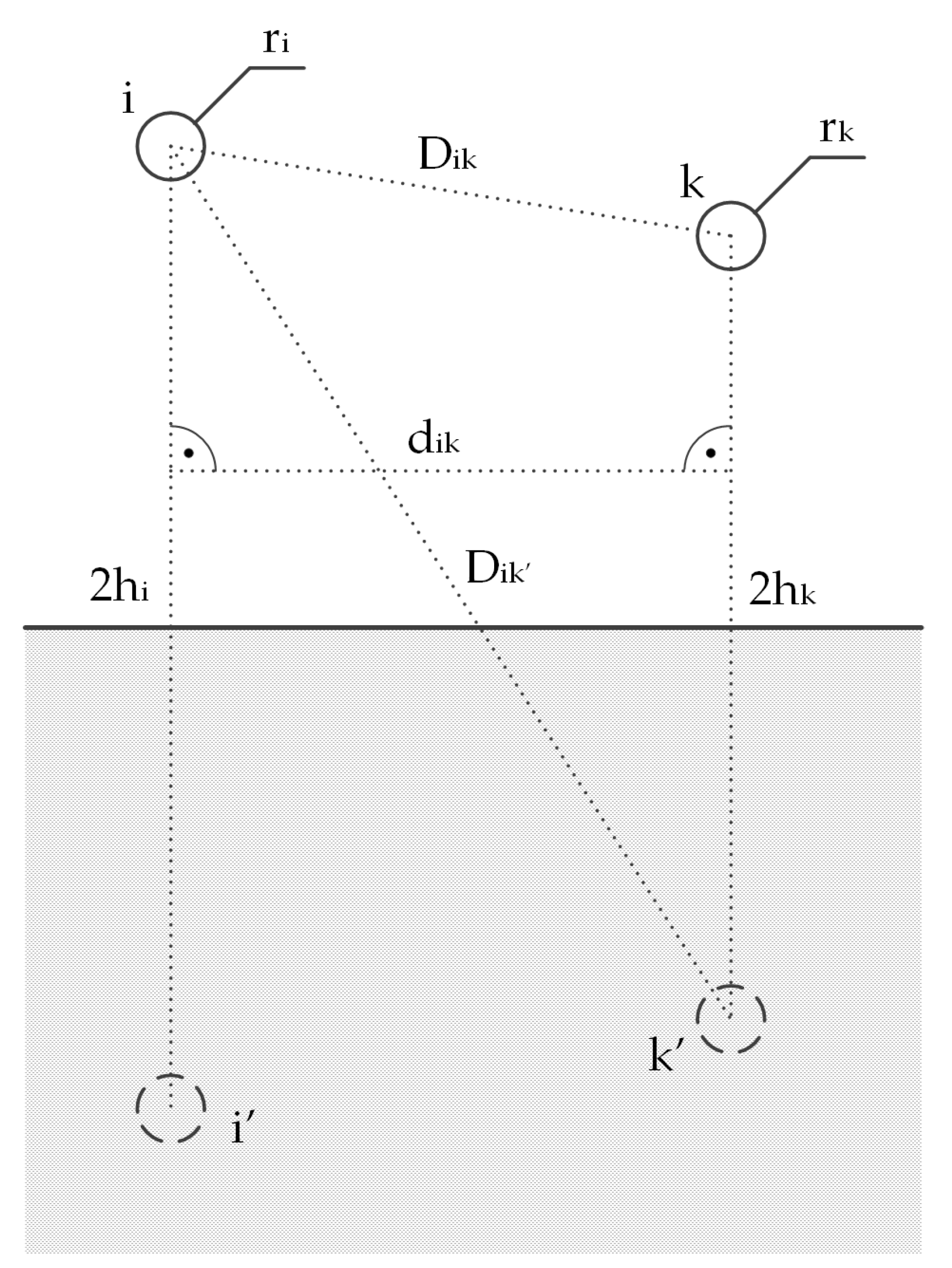
To calculate the self-impedance of the conductor “i” as pictured in Figure 1, following substitutions have to be made:
Resulting in:
To calculate the mutual impedance between the conductors “i” and “k” as pictured in the Figure 1, following substitutions have to be made:
Resulting in:
Final form of the series impedance matrix (simple N-phase system without a ground wire) is as follows:
If there are any ground wires present, the series impedance matrix will take following form:
where “N” index is the number of phase wires, and “M” index is the sum of the phase wires and ground wires.
2.2. Closed-Form Expressions for Series Impedance Matrix
However, the coefficients used in these formulas cannot be solved analytically because they are expressed in the form of infinite series [29] which is not very practical for engineering purposes. The closed forms (approximations) of the original equations simplify the computations of the overhead line impedances with as little inaccuracy as possible. The most common were obtained by:
- Carson-Clem [30]
- Introduced unified fictional earth return depth;
- Sunde [31]
- Introduced complex propagation constant in earth;
- Introduced fictional complex earth return depth;
- Alvarado–Betancourt [35]
- Increased numerical accuracy of Sunde and Dubanton’s closed-form expressions;
- Noda [26]
- Further extended the Dubanton’s complex earth return depth concept.
Their exact mathematical notation can be found summarized here [36,37,38], since it is not the main aim of this article. The resulting series impedance matrix is applicable for transposed as well as for untransposed overhead power lines, which is granting the universal application of all beforementioned expressions.
2.3. Positive and Zero-Sequence Impedance
The most useful format for the practical purposes is the symmetrical components transformation of the series impedance matrix [39]. A general procedure to obtain the positive and zero-sequence impedance is by using the transformation matrix and its inverse matrix as follows:
where:
If the series impedance matrix is not the N × N size, the Kron reduction needs to be implemented before the next step [40,41]. Then, the transformation into the symmetrical components for the square N × N series impedance matrix will be as follows:
where:
- is the N × N series impedance matrix
- —symmetrical components of the series impedance matrix
- —zero-sequence impedance
- —positive-sequence impedance
- —negative-sequence impedance
2.4. Positive Sequence Impedance per Phase
Overhead power line (OPL) protection setting often requires positive sequence impedance per phase value . N × N matrix for 3-phase system is:
Positive sequence impedance per phase are then calculated using classical approach (EMTP methodology) [40]:
Alternatively, they can be acquired by calculating phase-phase loop impedances ,
Positive sequence impedance per phase from phase loop are calculated as follows:
For transposed and untransposed lines OPL equals:
For transposed OPL equals:
Equation (20) is not equal for untransposed lines. Above statements can be easily proved by following the example of a 160 km 500 kV line from [39]. Matrix represents transposed line and matrix represents untransposed line. Both matrices are in per unit vales (Ω/mile). In the example, conductors are in horizontal configuration. Result may vary based on other conductor configurations, however inequality between positive sequence impedances calculation approaches per phase is preserved.
The results in Table 1 show values of calculated positive-sequence impedances per phase which gives the following conclusions:
- For transposed OPL
- ○
- (similar for other phases);
- ○
- Average values of positive sequence impedance per phase equals .
- For untransposed OPL
- ○
- (similar for other phases);
- ○
- can result into negative values of resistance (similar for other phases);
- ○
- Average values of positive sequence impedance per phase over equals ;
- ○
- Both positive sequence impedance per phase calculated by emtp methodology and by phase loop can be measured as it will be shown in Section 3.1.
3. Measurement of Overhead Power Line Impedances
The following section describes in great detail the general methodology and actual measurement apparatus for single system OPL measurement. The section also provides methodology for calculation of , and positive sequence impedance per phase (EMTP methodology, phase-phase loop) from measured voltages and currents. This methodology is mainly based on IEEE recommendations [18], except for measurements M3b and M4 which are the authors’ contribution. In general, presented measurements can be characterized by:
- Off-frequency measurement—frequencies at which impedances are measured differs from power frequency 50 Hz. This is for suppressing the interference with power frequency voltages and current induced by surrounding lines, traction lines, etc. In all measurements, frequency range of power source was used. Power frequency, 50 Hz, is omitted because OPLs already have naturally induced voltages from other parallel OPLs in their close vicinity and measured superposed signal is hard to distinguish.
- Off-line measurement—power line is disconnected from the power grid.
Equipment required for OPL measurement consist of:
- Power source (single-phase and three-phase);
- Inverter capable of generating sinusoidal waveforms in range 50 ± 10 Hz;
- Voltage and current measurement equipment.
A detailed description of the measuring apparatus is stated in Section 3.2.
3.1. Measurement Methodology
Based on connection of circuit and used power source there are several ways how to measure and then calculate from measured data impedances and .
In all measured cases, positive sequence resistance is a function of OPL temperature. It is standard nowadays to calculate and measure resistance at a temperature of 20 °C. In simple form, the resistance of ACSR conductor at can be expressed as follows [10]:
where:
- —is resistance at 20 °C
- —T is conductor temperature
- —is resistance at temperature
- —linear temperature coefficient
- —quadratic linear coefficient
3.1.1. M1—Three-Phase Symmetrical Measurement of Positive Sequence Impedance
As shown in Figure 2, the receiving terminals of OPL are shorted and grounded. Three-phase power source is connected to sending terminals of each phase. OPL phase voltages and currents in each phase are measured for every from .
Positive sequence impedance measured at frequency is calculated as follows:
Reactance is then recalculated to power frequency 50 Hz as follows:
Final is then calculated as an average value of :
where equals number of measured frequencies.
As can be seen in Equation (25), the measurement M1 gives us values of positive sequence impedances per phase which can be calculated by EMTP methodology, Equation (16), from impedance matrix. These values are further compared with other measurements and calculations.
The major disadvantage of this method is that the results are correct only with fully transposed line. In addition, this approach requires a more expensive three-phase source and other equipment. It will be shown in Section 4.4 that the result has slightly larger error compared to other measurement methods.
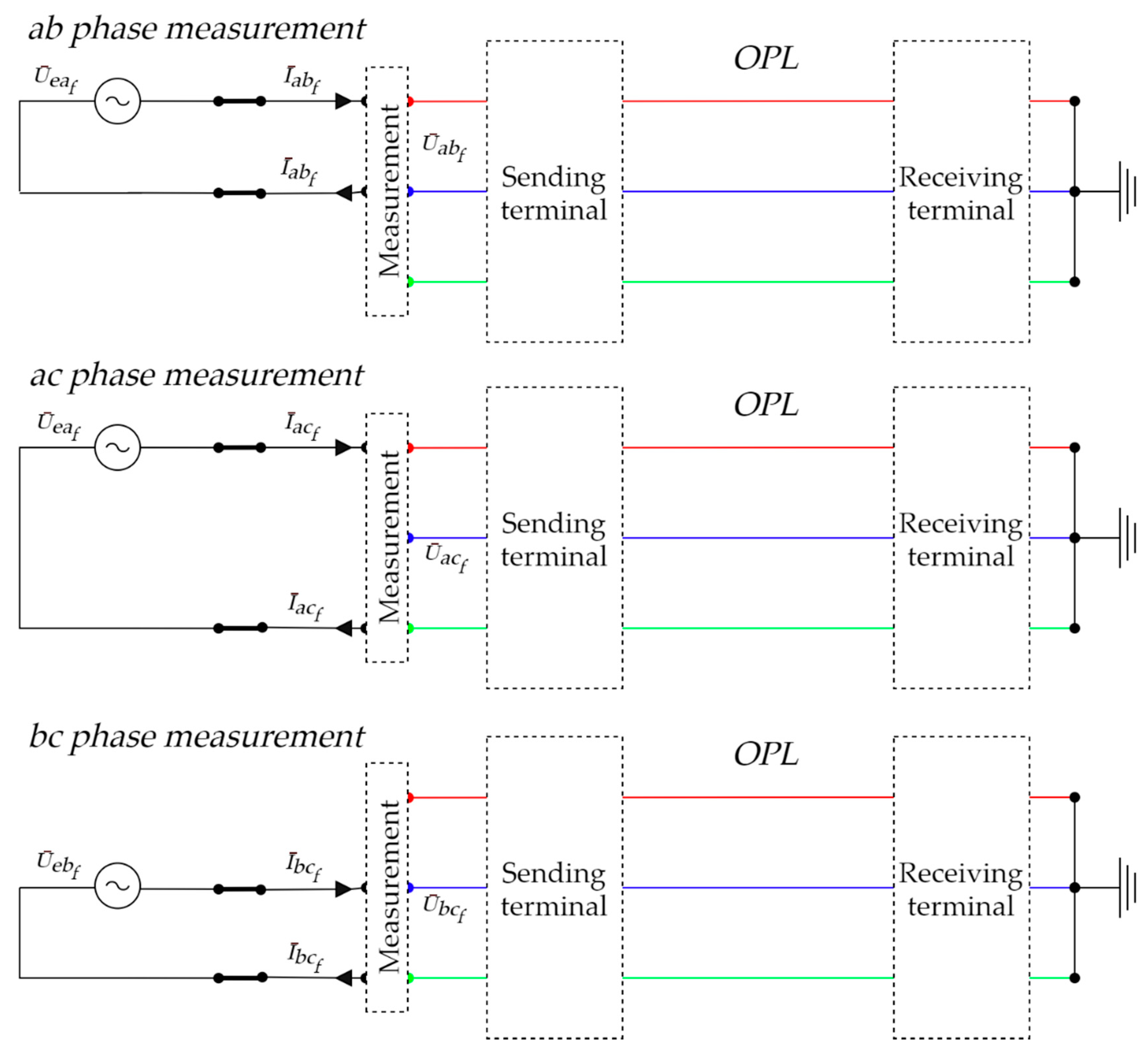
3.1.2. M2—Single-Phase Measurement of Positive Sequence Impedance by Phase-Phase Loops
As shown in Figure 3, the receiving terminals of OPL are shorted and grounded. Single-phase power source is ungrounded and connected to sending terminals between two measured phases at a time Figure 3. OPL line-line voltages for every loop and currents in each phase are measured for every value of from .
Positive sequence impedance measured at frequency is calculated as follows:
is calculated by recalculation reactance of to power frequency by Equation (26). Similiary and is calculated. Positive sequency impedance measured at frequency is then calculated as follows:
Final is then calculated as an average value of , Equation (27).
Positive sequence impedances pre phase , , measured at frequency are calculated from Equation (18). , , are calculated as an average value from .
3.1.3. M3—Single Phase Measurement of Positive and Zero Sequence Impedance by Phase-Ground Loops
As shown in Figure 4, the receiving terminals of OPL are shorted and grounded. Measurement consists of three separate measurements (1,2,3) during which a single-phase power source is connected individually to terminal of phases .
Measurement consists of following steps for every frequency :
- Power source is connected to first phase. OPL phase voltages (the first index value of voltage indicates the phase which induced voltage on the phase of the second index value) and current conductor are measured.
- Power source is connected to second phase. OPL voltages and current conductor are measured.
- Power source is connected to third phase. OPL voltages and current conductor are measured.
Impedance matrix is then constructed from the measured values as follows:
is then calculated by recalculation reactance of to power frequency as follows:
Matrix should by diagonally symmetrical. However, due to measurement, some error may occur. Therefore, the mean value of is calculated as follows.
where is transposed matrix . Using Equation (13), a matrix of symmetrical components is calculated from which and are extracted, Equation (14). Measurement is repeated for all frequencies in . and is then calculated as average over the frequencies, Equation (27).
Positive sequency impedances pre phase , , measured at frequency are calculated from by Equation (16). , , are calculated as an average value from .
Positive sequence impedances pre phase , , measured at frequency are calculated from by Equations (17) and (18). , , are calculated as an average value from .
3.1.4. M3b—Alternative Way of Calculating Zero Sequence Impedance by Phase-Ground Loops Measurement
The following evaluation of is based on measurement of by M2 and phase loop measurement specified in Section 3.1.2. Advantage of this approach are simple mathematical calculation and need of only single-phase power analyzer for measurement. Voltages of not connected phases to source are irrelevant. Only at , at and at are measured from measurement at Figure 4. From the following measurement line ground impedance (earth impedance + impedance of ground wire) is calculated as follows:
is calculated by recalculation reactance of to power frequebncy by Equation (26). Impedance can be writenn also as:
where is ground impedance and is positive sequence impedance measured by M2 measurement from phase-phase loops. Equation (34) can be rewritten as:
Zero sequence impedance can be generally expressed as:
Combining Equations (35) and (36) we get:
is then calculated as an average value of Equation (26).
3.1.5. M4—Three-Phase Measurement of Zero Sequence Impedance Using Single Phase Source
As shown in Figure 5, the receiving terminals of OPL are shorted and grounded. Sending terminal are shorted. Measurement consists of single measurements during which a single-phase power source is to OPL.
From the following measurement zero sequence impedance for every frequency is calculated as follows:
is calculated by recalculation reactance of to power frequency by Equation (26). is then calculated as an average value of , Equation (27).
3.2. Measuring Apparatus and Data Analysis
For measuring purposes, our own apparatus was created, the design of which was based on commonly available elements with an emphasis on measurement accuracy and plausibility of single-phase and three-phase measurement. In order to evaluate the measured values, the measuring apparatus is unique in the use of software harmonic filters, where the block scheme is shown in Figure 6.
A standard inverter with an apparent power of 20 kVA is used as a measurement source for supplying a measured power line. This measurement source is connected to an isolating transformer with a switching panel, which is used to change the configuration of the power supply with the possibility of connection to the power line conductors and create the possibility of connection to ground. As a block of voltage and current measurement is used precision voltage and current meter—Applied Precision RS2330E.
During the measurement, this device is used in oscilloscopic mode, while the measured values are real-time sampled waveform (RMS values are not measured). The measuring device has separated voltage and current circuits to eliminate the error caused by voltage drops. For this reason, the connection to the power line is realized by two separate branches, i.e., the voltage as well as the current branch have overvoltage protections.
3.3. Specification of Measuring Apparatus Components
Precision voltage and current meter Applied precision RS2330E:
- Highest accuracy 0.01% (optionally up to 0.005%);
- Wide measuring range 0.1 mA to 120 A and 0.1 V to 600 V;
- Bandwidth 10 kHz and sampling rate 24-bit 125,000 samples/second.
Inverter Vonsch Unifrem 400:
- Output voltage range 3 × 0 ÷ 400 V;
- Output frequency 0 ÷ 500 Hz;
- Electronic protection against overcurrent, overvoltage, undervoltage, short circuit protection and ground fault protection.
Isolating transformer:
- Connection Dyn1;
- Voltage 360/550 V;
- Nominal power 20 kVA;
- Frequency 40 ÷ 100 Hz.
3.4. Measurement Safety
Measurement on OPL requires specific safety procedures as follows:
- Measurement planning:
- ○
- Possible inductive coupling from parallel or in the close vicinity power line to the measured power line is necessary to verify by simulation in order to assess the measurement possibility, i.e., the risk of high values of open circuit voltage and short-circuit current on power source terminals is represented by the loading of the parallel power line.
- ○
- Based on the voltage and current conditions, it is necessary to decide on the possibility of measuring the power line during operation of the parallel line or on it shutting off.
- Measurement performing:
- ○
- Measured power line is grounded on both terminals and before the measurement, it is necessary to verify the open circuit voltage and short-circuit current values in all phases on receiving terminal.
- ○
- Based on the open circuit voltage and short-circuit current conditions, it is necessary to decide on the possibility of measuring the power line, i.e., if the voltage and current exceed maximum power, then the power source will not be able to supply measured power line and measurement is not possible to perform.
- ○
- The required connection of power source to OPLs, according to specific measurements (m1–m4) by switching panel.
- ○
- Measurement is performed for whole . The minimum source voltage is set when the power supply is first connected to the receiving terminal. Voltage is then slowly increased and the OPLs currents are monitored to not exceed the maximum current of the apparatus.
3.5. Sampled Waveform Processing
Measurement data are sampled waveforms for every frequency from , as defined in Equation (23). The selected measurement frequencies are close to the grid frequency, which means that the resulting signal is repeated with a frequency as follows:
where:
- —frequency of measured signal
- —frequency of power grid
- —frequency of power supply apparatus
Above equation shows that the sampled signal length of the oscilloscope recording must be more than . Our measured signal length from varies from 40 to 60 s. The longer time decrease Type A evaluation of uncertainty. Signal processing is done using LabVIEW custom software. Core of program is frequency filter function Extract Sine Tone. It finds the single tone with the highest amplitude or searches a specified frequency range, and returns the single tone frequency, amplitude, and its phase [42]. The difference between the measured frequency and the grid frequency is from 1 Hz to 7 Hz and in this case, it is not possible to build a reliable hardware filter. By this approach coupled signals are reliably filtered out. MATLAB software filters were also tested in the analysis and the results were equally accurate.
4. Comparison of Calculation, Simulation and Measurement Results
In the following part, overview information and results are provided for particular approaches of determining the impedance for a selected transmission line at 400 kV voltage level. These results are reciprocally compared in order to identify their accuracy, suitability for use and potential shortcomings of stated approaches.
4.1. Positive and Zero Sequence Impedance—Calculation
The investigated power line is defined by following parameters:
- (a)
- Towers’ geometry and height standardization
- ○
- “Y” type, Portal, Cat, “V” type
- ○
- +0/+4/+6/+8/+12/+14/+18
- (b)
- Phase arrangement
- ○
- As shown in Figure 2
- (c)
- Conductor/ground wires types
- ○
- Phase conductor:
- ▪
- 350AlFe4 (similar to 362-AL1/59-ST1A)
- ○
- Ground wires:
- ▪
- 185AlFe3 (similar to 184-AL3/72-A20SA)
- ▪
- Alcatel 24 Fo OPGW 147/59
- ▪
- 70Fe (steel wire)
- ▪
- AL4/A20SA 147/30-17.7
- (d)
- Span lengths
- ○
- Defined between every tower, total length 85.7863 km
- (e)
- Minimum clearing distance
- ○
- Usually from 8–12 m for the lowest conductor
- (f)
- Ground resistivity
- ○
- Usually from 50–200 Ωm
For the actual impedance computation, the MATLAB routine “power_lineparam” was used, which is utilizing the traditional Carson’s calculation methodology [43]. The complete power line is based on the line schedule, and it was divided on separate sections (as pictured in Figure 7), where every section has the same parameters (a), (b) and (c). The ground resistivity and minimum clearing distances of the lowest conductor are estimated through the calculation as constants. Span length is then divided and assigned to respective towers on its ends to ensure optimal distribution of the conductors’ height over the ground. Thanks to the span directly connected to the individual towers, it is possible to create the detailed model of the transmission line and therefore obtain the serial impedance matrix and also the symmetrical components of the impedance.
For the whole model, uniform ground resistivity of 100 Ωm was estimated, and the minimum clearing distance of the lowest conductor for each tower design was 8m. Final impedance matrix of calculated electrical parameters is then as follows:
Positive and zero sequence impedances, are then calculated from by Equation (14). Both types of positive sequence impedances per phase are evaluated, EMTP methodology Equation (16), and phase-phase loop calculation Equations (17) and (18). Following Table 2 shows calculated results. As it can be seen, stated values are not equal because the power line is not perfectly transposed (Section 2.4).
4.2. Positive and Zero Sequence Impedance—Simulation
As stated above, based on power line schedule, a detailed model of the transmission line was created. This model was complemented by the necessary elements of measurement and configuration in terms of the corresponding methodology (Section 3).
Positive and zero sequence impedances, are calculated based on measurement results in MATLAB Simulink (Figure 8). Positive sequence impedances per phase are evaluated, 1st from the 3-phase measurement directly, 2nd from the phase-phase loop measurement (needed also calculation Equation (18)) and 3rd from the phase-ground loop (needed also calculation Equation (30)). Zero sequence impedance is evaluated from the 3-phase measurement directly. Table 3 shows calculated results. As in previous results, it is possible to see that stated values are not equal because the power line is not perfectly transposed (Section 2.4).
4.3. Positive and Zero Sequence Impedance—Measurement
The power line impedance measurement was performed for 400 kV transmission line geographically located in the north part of Slovakia according to detailed parameters (see Section 4.1) where a simplified line schedule can be seen in Figure 9. This power line is characterized by an individual corridor with no crossings with other transmission power lines with the exception of perhaps 15 crossings with power lines at a 110 kV voltage level. There is only one exception of a parallel power line in close vicinity at the beginning from the measurement side location, which is particularly important regarding to safety precautions of the measurement.
Positive and zero sequence impedances, are calculated based on measurement results according to the stated methodology above (Section 3). Positive sequence impedances per phase are evaluated: 1st—directly by the 3-phase measurement, 2nd—the 1-phase measurement (phase-phase loop) (needed also calculation Equation (18)) and 3rd—the 1-phase measurement (phase-ground loop) (needed also calculation Equation (30)). Zero sequence impedance is evaluated by means of two approaches: (a) determination by the 1-phase measurement (phase-ground loop); (b) directly by the 3-phase measurement using single phase source. In addition, the measurement took place during an environmental temperature of 26 °C. That means that the measured and evaluated resistance values of conductor must be converted into the resistance at 20 °C by Equation (24), where linear temperature coefficient
α = 0.00403 K−1 and quadratic linear coefficient β = 8 × 10⁻⁷ K−1. In Table 4, the calculated results are shown.
4.4. Results Comparison
In the field of electrical parameters of power lines, research and analyses of modelling and measurement have been published in a relatively number scale of studies. Some studies were aimed at evaluating of calculation and simulation manners and some at measurement approaches.
In order to compare the calculation, simulation results and measurement results with each other, the calculated value of positive and zero sequence impedance is considered a reference value where the deviation is related precisely to these values. A comparison of the results of symmetrical components for the investigated 400kV transmission power line is shown in Table 5 and Table 6, comparison results of positive sequence impedance per phase in Table 7.
By comparing the results of the calculation (according to the line schedule) and the simulation, the largest error is achieved in the case of evaluation using the 3-phase measurement, specifically for resistance R1 4.54% and X1 reactance 0.70% compared to the calculation. This difference may be caused due to the evaluation methodology, as the measured power line is a real power line that is not fully transposed. Therefore, the asymmetry is proven to a considerable extent.
In the case of 1-phase measurement, specifically for approaches (a) phase-phase loop, and (b) phase-ground loop, the reactance results are almost equal, the error is at the level of 0.21% compared to the calculation. For R1 resistance, the error is 0.35% (phase-phase loop approach) and 2.22% (phase-ground loop approach) compared to the calculation.
By comparing the zero-sequence impedance, the results obtained by the three different approaches are comparable. In the case of evaluation using the 1-phase measurement, concretely a phase-ground loop and an alternative method of determining the zero-sequence, they are equal. Specifically, the resistance R0 error is 0.38% and the reactance X0 0.58% compared to the calculation. For 3-phase measurement using a single-phase source, the error for resistance R0 is at the level of 0.20% and the reactance X0 is 0.51% compared to the calculation.
On the other hand, by comparing the results of the calculation (according to line schedule) and the measurement, the smallest error is achieved in case of evaluation using the 3-phase measurement, specifically for resistance R1 0.27% and X1 reactance 0.31% compared to the calculation. However, in this case, it is necessary to emphasize the discrepancy with the statistics of the results of measuring the power line impedance. The authors’ experience shows that the impedance results obtained using the 3-phase measurement are the least accurate. Statistical processing of the results of a larger number of measurements will be the subject of further publication. The results of the phase values of the impedance (Table 7) show a parametric asymmetry, where the average of these values is the resulting positive-sequence impedance. Proof of this finding is also described in Section 2.4. Subsequently, this fact is also confirmed by the results of two different approaches of the 1-phase measurement (phase-phase loop, and phase-ground loop), where the resistance R1 error is at the level of 2.63% (2.68%) and reactance X1 0.52% (0.53%). The mentioned effect can be caused by, e.g., different boundary conditions in the power line schedule compared to the actual design and construction.
To compare the zero-sequence impedance, the results obtained by the three different approaches are comparable. In case of evaluation using a 1-phase measurement, concretely a phase-ground loop and an alternative method of determining the zero-sequence impedance, they are almost equal. Specifically, the resistance R0 error is 4.92% (4.99%) and the reactance X0 3.80% compared to the calculation. For 3-phase measurement using a single-phase source, the error for resistance R0 is 4.52% and reactance X0 3.81% compared to the calculation.
The results show that the calculation and measurement may differ, even though the calculation is performed according to a line schedule. For this reason, there is a need as well as a requirement to verify the line impedance by measurement in order to obtain accurate values.
Based on the achieved results, it can be stated for determination of the power line impedance, there is necessary interpretation divided into two frameworks:
- Positive-sequence and zero-sequence impedance (as average of phases values):
- ○
- Impedance value suitable in symmetrical models in power systems.
- Positive-sequence impedance (per phase):
- ○
- Impedance values per phase suitable in asymmetric models in power systems, as well as for correct setting of the distance protections.
5. Discussion on Measurement and Calculation Results, and On-Line Measurement
As already mentioned, the calculated impedance value is considered in this paper as the reference value. However, in the case of the calculation, it is necessary to point out the uncertainties as well. In particular, the calculation of power line impedance based on the line schedule may not be completely accurate for the following reasons:
- -
- Considered constant earth resistivity, i.e., the value of the ground resistivity influences the impedance of the phase-ground loop, that means it has an impact on the positive-sequence impedance of the untransposed power line and on the zero-sequence impedance;
- -
- Considered constant conductors sag and no considered terrain jaggedness under the power line, i.e., slightly affects the ground return current under the power line and thus the magnitude of the zero-sequence impedance;
- -
- No other power lines in the vicinity considered, in particular ground conductor, i.e., ground conductors in the vicinity of the measured power line can significantly affect the magnitude of the zero-sequence impedance;
- -
- The final length is based on the line schedule, i.e., the actual real length was not verified by measurement (based on our experience, we know that these lengths can often vary).
It can be stated that, with regard to all analyzed results, complexity and accuracy of evaluated methodologies, the 1-phase measurement methodology, specifically phase-ground loop, can be described as the most appropriate approach of determining power line impedance (resistance and reactance).
Currently, the trend in determining the power line parameters in many publications, e.g., [18,19,20,21,22,23], indicates the use of PMU, i.e., determination of power line parameters by on-line method from the measured voltage and current phasors. Regarding to our paper, we deal with the off-line measurement of power line parameters with no possibilities for on-line measurement, since the OPL needs to be powered off during the measurement. Furthermore, we want to point out the shortcomings and uncertainties of the on-line method using the PMU.
As a first problem of the online method, the roll-out of voltage and current phasor (PMU) measurements is missing in many power systems, especially in distribution networks. That means, the TSO’s (transmission system operator), but especially DSO’s (distribution system operator), would not avoid to determination of some power lines parameters by off-line measurement. In this case, it would probably weigh the argument of a uniform methodology of determining the power line parameters in the power system.
As a second and fundamental shortcoming, there are errors in synchronization of data acquisition and accuracy of voltage and current phasor measurement, as the accuracy of CT (current transformers) and VT (voltage transformers) also contributes to the measurement error. The accuracy of voltage and current phasor angle measurements can be limiting in determining power line parameters with the required accuracy. In particular, the parameters determination of short lines or lightly loaded power lines, i.e., when the transmission angles on the power line (the difference between the angles of the voltage phasors at the beginning and the end of the line) are very small, the accuracy of measuring of voltage phasors angles is very important for the accuracy of determining the parameters of a given power line. The mentioned problem is analyzed in [3,4].
Another shortcoming, (considering the IEEE methodology [6]), is the need to implement manipulations—switching off one phase of the power line to determine zero-sequence impedance, which, especially in transmission systems, may not be acceptable for the TSO.
In future research, we would like to focus our attention on comparing the results of determining power line parameters using off-line and on-line methods.
6. Conclusions
This paper describes calculation and measurements methods of the overhead power lines in order to evaluate electrical parameters. Mainly, attention is focused on the exact evaluation of the impedance of the investigated overhead power line by calculation, and subsequent comparison with evaluation obtained from the simulation results and different measurement approaches. Differences between calculation and experimental measurement are shown and discussed with a focus on the identification of potential uncertainties.
In general, the following two factors need to be considered when selecting an appropriate measurement methodology for determining power line impedance:
- Purpose of use;
- Accuracy.
In regard to a purpose of use, based on the analysis of off-line measurement results, the following applies to given measurement approaches:
- 3-phase measurement:
- ○
- Same measurement conditions for determining the zero-sequence impedance , i.e., after manipulation on the measurement side (interconnection of phases behind the source), the measurement is performed for only one configuration;
- ○
- Not suitable for determining the phase values impedance of power line;
- ○
- To determine the positive-sequence impedance (as the average of phase values) is sufficient—with regard to the time management of measurement and the number of manipulations on the measuring apparatus during the measurement;
- ○
- Use of impedance value in symmetrical models in power systems;
- ○
- Disadvantage: 3-phase power source is required.
- 1-phase measurement:
- ○
- Different measurement conditions for determining the zero-sequence impedance , i.e., it is necessary to perform measurements for at least three configurations, but to determine the zero-sequence impedance there are 2 ways to evaluate this value;
- ○
- Accurate results for determining the phase values impedance of the power line;
- ○
- Use of impedance values per phase also in asymmetric models in power systems, as well as for correct setting of the distance protections;
- ○
- Advantage: 1-phase power source is required.
In regard to an accuracy, it can be stated that 1-phase measurement (phase-phase loop, phase-ground loop) can be considered as exact methods of off-line measurement for determining the positive-sequence impedance. In addition, 1-phase measurement (phase-ground loop) as well as three-phase measurement using a single-phase source can be considered as an accurate measurement for determining the zero-sequence impedance.
Based on the above, it is clear that accurate electrical parameters (impedances) of overhead power lines used for example in simulation calculations, short-circuit calculations or correct setting of electrical relays are significant. In order to achieve stated requirements in practice, it is necessary to have the correct input data. These data may not be sufficient only from line schedule calculation, but also should be verified by measurement.
There are several areas where we see potential further research regarding the comprehensiveness of the electrical parameters’ measurement of overhead power lines (impedance, admittance):
- Statistical processing of the results of a larger number of measurements of power line impedances using 3-phase measurement;
- Calculation and measurement comparison of power line capacity (positive-sequence admittance, zero-sequence admittance);
- Identification and assessment of the influence of facts/phenomena/parameters influencing the size of power system admittance.
There are several areas where further research can lead, regarding on-line measurement:
- Analysis of measured data from PMU for selected power lines;
- Analysis and assessment of the influence of different measuring devices/equipment on measurement deviations;
- Quantification of deviations in the determination of power line parameters using the off-line method and the on-line method with regard to the different operating states of the power lines;
- Determine the conditions of usability of the calculated parameters from the on-line measurement;
- Comparing the results of determining power line parameters using off-line and on-line methods.
Author Contributions
Conceptualization B.C., Ž.E., P.J. and A.B.; Formal analysis, M.C. and J.B.; Funding acquisition, A.B.; Investigation, B.C., M.C. and J.B.; Methodology, B.C., Ž.E., J.B. and A.B.; Project administration, A.B.; Software, B.C., M.C., P.J. and J.B.; Supervision, A.B.; Validation, M.C., P.J. and J.B.; Visualization, M.C., P.J. and J.B.; Writing—original draft, B.C., M.C., P.J. and J.B.; Writing—review and editing, M.C., J.B. and A.B. All authors have read and agreed to the published version of the manuscript.
Funding
This publication was created thanks to support under the Operational Program Integrated Infrastructure for the project: International Center of Excellence for Research on Intelligent and Secure Information and Communication Technologies and Systems—II. stage, ITMS code: 313021W404, co-financed by the European Regional Development Fund.
Institutional Review Board Statement
Not applicable.
Informed Consent Statement
Not applicable.
Data Availability Statement
Data are contained within the article.
Acknowledgments
We would like to thank the Applied Precision Ltd. Company for renting out the device Reference Standard RS 3330E for free. The device was used for measuring of the frequency characteristics of appliances concerning this project—appliedp.com.
Conflicts of Interest
The authors declare no conflict of interest.
References
- Pohjanheimo, P.; Lakervi, E. Steady state modeling of custom power components in power distribution networks. In Proceedings of the 2000 IEEE Power Engineering Society Winter Meeting. Conference Proceedings (Cat. No.00CH37077), Singapore, 23–27 January 2000; Volume 4, pp. 2949–2954. [Google Scholar]
- Zhang, J.; Wen, H.; Teng, Z.; Martinek, R.; Bilik, P. Power System Dynamic Frequency Measurement Based on Novel Interpolated STFT Algorithm. Adv. Electr. Electron. Eng. 2017, 15, 365–375. [Google Scholar] [CrossRef]
- Wannous, K.; Toman, P. Evaluation of Harmonics Impact on Digital Relays. Energies 2018, 11, 893. [Google Scholar] [CrossRef] [Green Version]
- Shi, D.; Tylavsky, D.; Logic, N.; Koellner, K. Identification of short transmission-line parameters from synchrophasor measurements. In Proceedings of the 2008 40th North American Power Symposium, Calgary, AB, Canada, 28–30 September 2008. [Google Scholar]
- Ptacek, M.; Vycital, V.; Toman, P.; Vaculik, J. Analysis of Dense-Mesh Distribution Network Operation Using Long-Term Monitoring Data. Energies 2019, 12, 4342. [Google Scholar] [CrossRef] [Green Version]
- Kanálik, M.; Margitová, A.; Dolník, B.; Medveď, D.; Pavlík, M.; Zbojovský, J. Analysis of low-frequency oscillations of electrical quantities during a real black-start test in Slovakia. Int. J. Electr. Power Energy Syst. 2021, 124, 106370. [Google Scholar] [CrossRef]
- Houdek, V.; Král, V.; Rusek, S.; Gono, R. Input parameters for restoration method for 110 kV power line. Prz. Elektrotechniczny 2013, 89, 4–7. [Google Scholar]
- Enegela, O. Ageing of Overhead Conductors. Ph.D. Thesis, The University of Manchester, Manchester, UK, 2013. [Google Scholar]
- Hannam, J.; Dam, R.V.; Harmon, R. Workshop on Soil Magnetism: Multi-Disciplinary Perspectives, Emerging Applications and New Frontiers Report. Available online: https://www.semanticscholar.org/paper/Workshop-on-Soil-Magnetism%3A-Multi-disciplinary-and-Hannam-Dam/9443d3fe93146b795a13dc4f7e12748eef8566ac (accessed on 10 September 2021).
- CIGRE. WG B2.42 TB 601-Guide for Thermal Rating Calculations of Overhead Lines; CIGRE: Paris, France, 2014; ISBN 978-2-85873-302-6. [Google Scholar]
- Bendík, J.; Cenký, M.; Eleschová, Ž.; Beláň, A.; Cintula, B. Influence of different weather conditions on the maximum load current of overhead power lines. In Proceedings of the 2018 19th International Scientific Conference on Electric Power Engineering (EPE), Brno, Czech Republic, 16–18 May 2018; pp. 1–4. [Google Scholar]
- Cenký, M. Electrical Parameters of Overhead Power Lines. Ph.D. Thesis, Slovak University of Technology in Bratislava, Bratislava, Slovakia, 2018. [Google Scholar]
- Engineering ToolBox Permeability. Available online: https://www.engineeringtoolbox.com/permeability-d_1923.html (accessed on 18 September 2021).
- Zaborszky, J.; Rittenhouse, J.W. Electric Power Transmission: The Power System in the Steady State; Ronald Press Company: New York, NY, USA, 1954. [Google Scholar]
- Dommel, H.W. Overhead Line Parameters From Handbook Formulas And Computer Programs. IEEE Trans. Power Appar. Syst. 1985, PAS-104, 366–372. [Google Scholar] [CrossRef]
- Siranec, M.; Höger, M.; Otcenasova, A. Advanced Power Line Diagnostics Using Point Cloud Data—Possible Applications and Limits. Remote. Sens. 2021, 13, 1880. [Google Scholar] [CrossRef]
- Cenký, M.; Bendík, J.; Eleschová, Ž. Advanced methods for computation of electrical parameters for overhead transmission lines. J. Electr. Eng. 2017, 68, 143–147. [Google Scholar] [CrossRef] [Green Version]
- IEEE. IEEE Guide for the Parameter Measurement of AC Transmission Lines; IEEE Std 1870-2019; IEEE: Piscataway, NJ, USA, 2019; pp. 1–99. [Google Scholar]
- Kononov, Y.G.; Rybasova, O.S.; Sidirov, K.A. Identification of Overhead-Line Parameters from PMU Data with Compensation of Systematic Measurement Errors. In Proceedings of the 2018 International Conference on Industrial Engineering, Applications and Manufacturing (ICIEAM), Moscow, Russia, 15–18 May 2018; pp. 1–5. [Google Scholar]
- Vicol, B. On-line overhead transmission line And transformer parameters identification based on PMU measurements. In Proceedings of the 2014 International Conference and Exposition on Electrical and Power Engineering (EPE), Iasi, Romania, 16–18 October 2014; pp. 1045–1050. [Google Scholar]
- Ivanov, I.; Murzin, A. Synchrophasor-based transmission line parameter estimation algorithm taking into account measurement errors. In Proceedings of the 2016 IEEE PES Innovative Smart Grid Technologies Conference Europe (ISGT-Europe), Ljubljana, Slovenia, 9–12 October 2016; pp. 1–6. [Google Scholar]
- Ritzmann, D.; Holderbaum, W.; Potter, B.; Wright, P. Improving the accuracy of synchrophasor-based overhead line impedance measurement. In Proceedings of the 2015 IEEE International Workshop on Applied Measurements for Power Systems (AMPS), Aachen, Germany, 23–25 September 2015; pp. 132–137. [Google Scholar]
- Vicol, B.; Gavrilaş, M.; Ivanov, O.; Neagu, B.; Grigoras, G. Synchrophasor measurement method for overhead line parameters estimation in MV distribution networks. In Proceedings of the 2014 16th International Conference on Harmonics and Quality of Power (ICHQP), Bucharest, Romania, 25–28 May 2014; pp. 862–865. [Google Scholar]
- OMICRON Line Impedance Measurement. Available online: https://www.omicronenergy.com/en/solution/ (accessed on 4 August 2021).
- Carson, J.R. Wave propagation in overhead wires with ground return. Bell Syst. Tech. J. 1926, 5, 539–554. [Google Scholar] [CrossRef]
- Noda, T. A double logarithmic approximation of Carson’s ground-return impedance. IEEE Trans. Power Deliv. 2006, 21, 472–479. [Google Scholar] [CrossRef]
- Nakagawa, M.; Iwamoto, K. Earth-return impedance for the multi-layer case. IEEE Trans. Power Appar. Syst. 1976, 95, 671–676. [Google Scholar] [CrossRef]
- Pollaczek, F. Uber das Feld einer unendlich langen wechselstromdurchflossen Einfachleitung. Elektrishe Nachr.-Tech. 1926, 3, 339–359. [Google Scholar]
- Iracheta-Cortez, R. A recursive formula for the evaluation of earth return impedance on buried cables. Ing. Investig. 2015, 35, 34–43. [Google Scholar]
- Dommel, H.W. (Discussion of) IEEE Working Group Electromagnetic Effects of Overhead Transmission Lines Practical Problems, Safeguards, and Methods of Calculation. IEEE Trans. Power Appar. Syst. 1974, PAS-93, 892–904. [Google Scholar]
- Sunde, E.D. Earth Conduction Effects in Transmission Systems; Dover Publications: New York, NY, USA, 1968. [Google Scholar]
- Dubanton, C. Calcul Approché des Paramètres Primaires et Secondaires d’Une Ligne de Transport, Valeurs Homopolaires. EDF Bull. Dir. Études Rech. Série B-Réseaux Électriques Matériels Électriques 1969, 1, 53–62. [Google Scholar]
- Gary, C. Approche complète de la propagation multifilaire en haute fréquence par utilisation des matrices complexes. EDF Bull. Dir. Des Études Rech. Série B-Réseaux Électriques Matériels Électriques 1976, 1, 5–20. [Google Scholar]
- Déri, Á.; Tevan, G. Mathematical verification of Dubanton’s simplified calculation of overhead transmission line parameters and its physical interpretation. Arch. Elektrotechnik 1981, 63, 191–198. [Google Scholar] [CrossRef]
- Alvarado, F.L.; Betancourt, R. An accurate closed-form approximation for ground return impedance calculations. Proc. IEEE 1983, 71, 279–280. [Google Scholar] [CrossRef]
- Papadopoulos, T.A.; Chrysochos, A.I.; Traianos, C.K.; Papagiannis, G. Closed-Form Expressions for the Analysis of Wave Propagation in Overhead Distribution Lines. Energies 2020, 13, 4519. [Google Scholar] [CrossRef]
- Ramos-Leaños, O.; Naredo, L.; Moreno, P. Assessment of approximate formulas for calculating overhead-line earth-impedances. In Proceedings of the 2008 40th North American Power Symposium, Calgarym, AB, Canada, 28–30 September 2008. [Google Scholar]
- Tu, P.; Tlusty, J. The calculated methods of a frequency-dependent series impedance matrix of overhead transmission lines with a lossy ground for transient analysis problem. In Proceedings of the Large Engineering Systems Conference on Power Engineering, Montreal, QC, Canada, 7–9 May 2003; p. 163, ISBN 978-0-7803-7863-6. [Google Scholar]
- Schweitzer, E.O.; Zocholl, S.E. Introduction to Symmetrical Components; Schweitzer Engineering Laboratories, Inc.: Pullman, WA, USA, 2004. [Google Scholar]
- Dommel, H.W. EMTP Theory Book; Microtran Power System Analysis Corporation: Vancouver, BC, Canada, 1992. [Google Scholar]
- Glover, J.D.; Sarma, M.S.; Overbye, T. Power Systems Analysis and Design, 4th ed.; CL Engineering: Campsie, Australia; Toronto, ON, Canada, 2007; ISBN 978-0-534-54884-1. [Google Scholar]
- SingleToneInfo-LabWindows/CVI 2017 Help-National Instruments. Available online: https://zone.ni.com/reference/en-XX/help/370051AG-01/cvi/libref/cvisingletoneinfo/ (accessed on 8 September 2021).
- MATLAB Power_Lineparam-Compute RLC Parameters of Overhead Transmission Line. Available online: https://www.mathworks.com/help/physmod/sps/powersys/ref/power_lineparam.html (accessed on 4 August 2021).
Figure 1.
Configuration of the two-wire system above ground as introduced by Carson. All the symbols represent the distances between the conductors “i” and “k”, and their mirror images in the ground.
Figure 1.
Configuration of the two-wire system above ground as introduced by Carson. All the symbols represent the distances between the conductors “i” and “k”, and their mirror images in the ground.

Figure 2.
M1—Three-phase symmetrical measurement of positive sequence impedance.

Figure 3.
M2—Single-phase measurement of positive sequence impedance by phase-phase loops.

Figure 4.
M3—Single phase measurement of positive and zero sequence impedance by phase-ground loops.
Figure 4.
M3—Single phase measurement of positive and zero sequence impedance by phase-ground loops.

Figure 5.
M4—Three-phase measurement of zero sequence impedance using single phase source.

Figure 6.
Block scheme of measuring apparatus.

Figure 7.
Complete MATLAB Simulink model of the investigated overhead 400 kV power line. The crossed connectors between blocks are symbolizing the phase transposition.
Figure 7.
Complete MATLAB Simulink model of the investigated overhead 400 kV power line. The crossed connectors between blocks are symbolizing the phase transposition.

Figure 8.
Complete MATLAB Simulink model for determination of positive and zero sequence impedance by simulation (example of 3-phase symmetrical measurement of positive sequence impedance).
Figure 8.
Complete MATLAB Simulink model for determination of positive and zero sequence impedance by simulation (example of 3-phase symmetrical measurement of positive sequence impedance).

Figure 9.
Simplified picture of the route and schedule of measured transmission power line.


Table 1.
Results of positive sequence impedances per phase calculated by two different approaches for transposed and untransposed OPL.
Table 1.
Results of positive sequence impedances per phase calculated by two different approaches for transposed and untransposed OPL.
| Transposed OPL | Untransposed OPL | ||||
|---|---|---|---|---|---|
| EMTP methodology | 0.012 | 0.262 | 0.041 | 0.268 | |
| 0.012 | 0.262 | 0.012 | 0.251 | ||
| 0.012 | 0.262 | −0.017 | 0.268 | ||
| 0.012 | 0.262 | 0.012 | 0.262 | ||
| Phase-phase loop | 0.012 | 0.262 | 0.012 | 0.285 | |
| 0.012 | 0.262 | 0.012 | 0.217 | ||
| 0.012 | 0.262 | 0.012 | 0.285 | ||
| 0.012 | 0.262 | 0.012 | 0.262 | ||
Table 2.
Calculation results of symmetrical components (per phase as well).
| X (Ω) | |||
|---|---|---|---|
| Matrix calculation | 2.609 | 25.743 | |
| 16.842 | 65.930 | ||
| EMTP | 1.787 | 24.017 | |
| 0.860 | 26.063 | ||
| 5.180 | 27.151 | ||
| Phase-phase loop | 2.536 | 21.530 | |
| 2.638 | 27.955 | ||
| 2.652 | 27.745 |
Table 3.
Simulation results of symmetrical components (per phase).
| 3-phase measurement (per phase) | 2.440 | 23.889 | |
| 0.688 | 26.145 | ||
| 5.054 | 26.655 | ||
| Phase-phase loop | 2.537 | 21.569 | |
| 2.633 | 27.851 | ||
| 2.630 | 27.973 | ||
| Phase-ground loop | 2.602 | 21.568 | |
| 2.703 | 27.849 | ||
| 2.695 | 27.975 | ||
| Zero sequence | 16.876 | 66.265 |
Table 4.
Measurement results of symmetrical components (per phase).
| 3-phase measurement (per phase) | 2.371 | 2.312 | 23.924 | |
| 0.648 | 0.632 | 26.282 | ||
| 4.989 | 4.863 | 26.783 | ||
| Phase-phase loop | 2.519 | 2.456 | 21.593 | |
| 2.645 | 2.579 | 27.956 | ||
| 2.653 | 2.586 | 28.087 | ||
| Phase-ground loop | 2.517 | 2.454 | 21.606 | |
| 2.643 | 2.577 | 27.954 | ||
| 2.639 | 2.573 | 28.069 | ||
| Zero sequence (determination from phase-ground loop) | 16.001 | - | 63.422 | |
| Zero sequence | 16.080 | - | 63.421 |
* converted resistance values into the resistance at 20 °C.
Table 5.
Comparison of simulation results of investigated power line.
| Measurement | Calculation | 2.609 | 25.743 | 16.842 | 65.930 |
|---|---|---|---|---|---|
| M1 | simulation | 2.727 | 25.563 | - | - |
| error (%) | 4.54 | 0.70 | - | - | |
| M2 | simulation | 2.600 | 25.798 | - | - |
| error (%) | 0.35 | 0.21 | - | - | |
| M3 | simulation | 2.667 | 25.797 | 16.906 | 66.310 |
| error (%) | 2.22 | 0.21 | 0.38 | 0.58 | |
| M3b | simulation | - | - | 16.906 | 66.309 |
| error (%) | - | - | 0.38 | 0.58 | |
| M4 | simulation | - | - | 16.876 | 66.265 |
| error (%) | - | - | 0.20 | 0.51 |
* converted resistance values into the resistance at 20 °C.
Table 6.
Comparison of measurement results of investigated power line.
| Measurement | Calculation | 2.609 | 25.743 | 16.842 | 65.930 |
|---|---|---|---|---|---|
| M1 | measurement | 2.602 | 25.663 | - | - |
| error (%) | 0.27 | 0.31 | - | - | |
| M2 | measurement | 2.540 | 25.878 | - | - |
| error (%) | 2.63 | 0.53 | - | - | |
| M3 | measurement | 2.539 | 25.876 | 16.013 | 63.427 |
| error (%) | 2.68 | 0.52 | 4.92 | 3.80 | |
| M3b | measurement | - | - | 16.001 | 63.422 |
| error (%) | - | - | 4.99 | 3.80 | |
| M4 | measurement | - | - | 16.08 | 63.421 |
| error (%) | - | - | 4.52 | 3.81 |
* converted resistance values into the resistance at 20 °C.
Table 7.
Comparison results of positive sequence impedance per phase.
| Measurement | Calculation | 2.609 | 25.743 | |
|---|---|---|---|---|
| M1 | measurement | 2.312 | 23.924 | |
| 0.632 | 26.282 | |||
| 4.863 | 26.783 | |||
| simulation | 2.440 | 23.889 | ||
| 0.688 | 26.145 | |||
| 5.054 | 26.655 | |||
| M2 | measurement | 2.456 | 21.593 | |
| 2.579 | 27.956 | |||
| 2.586 | 28.087 | |||
| simulation | 2.537 | 21.569 | ||
| 2.633 | 27.851 | |||
| 2.630 | 27.973 | |||
| M3 | measurement | 2.454 | 21.606 | |
| 2.577 | 27.954 | |||
| 2.573 | 28.069 | |||
| simulation | 2.602 | 21.568 | ||
| 2.703 | 27.849 | |||
| 2.695 | 27.975 |
* converted resistance values into the resistance at 20 °C
Publisher’s Note: MDPI stays neutral with regard to jurisdictional claims in published maps and institutional affiliations. |
© 2021 by the authors. Licensee MDPI, Basel, Switzerland. This article is an open access article distributed under the terms and conditions of the Creative Commons Attribution (CC BY) license (https://creativecommons.org/licenses/by/4.0/).
Share and Cite
MDPI and ACS Style
Cintula, B.; Eleschová, Ž.; Cenký, M.; Janiga, P.; Bendík, J.; Beláň, A. Three-Phase and Single-Phase Measurement of Overhead Power Line Impedance Evaluation. Energies 2021, 14, 6314. https://doi.org/10.3390/en14196314
AMA Style
Cintula B, Eleschová Ž, Cenký M, Janiga P, Bendík J, Beláň A. Three-Phase and Single-Phase Measurement of Overhead Power Line Impedance Evaluation. Energies. 2021; 14(19):6314. https://doi.org/10.3390/en14196314
Chicago/Turabian StyleCintula, Boris, Žaneta Eleschová, Matej Cenký, Peter Janiga, Jozef Bendík, and Anton Beláň. 2021. "Three-Phase and Single-Phase Measurement of Overhead Power Line Impedance Evaluation" Energies 14, no. 19: 6314. https://doi.org/10.3390/en14196314
Note that from the first issue of 2016, this journal uses article numbers instead of page numbers. See further details here.