
A Novel Tripod Concept for Onshore Wind Turbine Towers


1
Institute of Steel Structures, National Technical University of Athens, GR-15780 Athens, Greece
2
Ergon Analysis Consulting Engineers L.P., GR-15122 Marousi, Greece
3
Ateş Wind Power, TR-35720 İzmir, Turkey
*
Author to whom correspondence should be addressed.
Energies 2021, 14(18), 5772; https://doi.org/10.3390/en14185772
Submission received: 24 July 2021
/
Revised: 25 August 2021
/
Accepted: 4 September 2021
/
Published: 13 September 2021
(This article belongs to the Special Issue Advances in Wind Energy Structures)
Abstract
:A wind turbine tower assembly is presented, consisting of a lower “tripod section” and an upper tubular steel section, aiming at enabling very tall hub heights for optimum exploitation of the wind potential. The foundation consists of sets of piles connected at their top by a common pile cap below each tripod leg. The concept can be applied for the realization of new or the upgrade of existing wind turbine towers. It is adjustable to both onshore and offshore towers, but emphasis is directed towards overcoming the stricter onshore transportability constraints. For that purpose, pre-welded individual tripod parts are transported and are then bolted together during erection, contrary to fully pre-welded tripods that have been used in offshore towers. Alternative constructional details of the tripod joints are therefore proposed that address the fabrication, transportability, on-site erection and maintenance requirements and can meet structural performance criteria. The main structural features are demonstrated by means of a typical case study comprising a 180-m-tall tower, consisting of a 120-m-tall tubular superstructure on top of a 60-m-tall tripod substructure. Realistic cross-sections are calculated, leading to weight and cost estimations, thus demonstrating the feasibility and competitiveness of the concept.
1. Introduction
In our era of massive energy consumption, the depletion of conventional energy sources and increased awareness of environmental parameters, alternative energy sources are constantly gaining ground. As an example, the EU has set a target to achieve at least 32% energy production from renewable sources by 2030 [1]. Even higher global targets have been set for a sustainable transformation to clean energy sources during the 26th Conference of the Parties (COP26) of the United Nations Framework Convention on Climate Change, where wind energy, as an efficient and cost-effective energy source, has a significant footprint with a required annual additional capacity of more than 350 GW starting in 2030 [2]. These targets are solely pointing out the huge demand and challenge compared to the total global installed wind energy capacity of 743 GW up to 2021 [3]. As the importance of the Levelized Cost of Energy (LCoE) of wind turbines inevitably increases, several aspects, such as the aerodynamic elements of the rotor, the electrical mechanisms for power extraction and the areas where wind power plants are installed, are continuously optimized to provide the highest possible power output [4,5,6,7,8]). Towers, as an inherent part of the wind turbine, deserve and receive similar attention.
Today, the most commonly used wind turbine tower type is the cantilever tubular steel tower, consisting of a number of cylindrical and/or conical shell parts [9,10]. Such towers are fabricated in a factory by (i) roller-bending a flat steel plate into a can with the desired cylindrical or conical shape, (ii) butt-welding the two adjacent longitudinal edges of the can to each other to form a closed shell, usually 2.5 m to 3.0 m long, depending on the available steel plates, and (iii) butt-welding consecutive cans to each other to form longer sections, most of which are in the range of 20–30 m, as dictated by the transportability limitations. Then, the sections are transported to the wind farm site by trucks, lifted by cranes or helicopters and bolted to each other with fully preloaded bolts using ring flanges that have been pre-welded at the ends of the sections.
The structural design of such towers has attracted the attention of many researchers (i.e., references [11,12,13,14,15,16]). Prevailing failure modes that dictate the design and determine the required cross-sections are the buckling of the tubular shells [17,18,19], fatigue of the connections [20,21,22] and avoidance of resonance between the tower’s fundamental frequencies and the rotor and blade-passing frequencies, denoted as 1P and 3P, respectively [10,23]. Required structural design verifications are described in pertinent recommendations [24,25,26,27] and guidelines [28,29,30]. Issues that have attracted particular attention include the arrangement of stiffening rings to improve buckling resistance [31,32,33], measures to recover the lost strength and stiffness due to the man-door opening near the tower base [34,35,36,37,38] and the design of ring flange connections between consecutive segments [39,40]. Extensive research efforts have been directed towards structural analysis and design methods [41,42,43,44,45,46,47], as well as towards optimizing the design to achieve reduced tower weight and cost [10,48,49,50,51].
However, in spite of all optimization attempts, conventional tubular steel towers seem to have nearly exhausted their potential for enabling further progress of the wind energy sector. Major increases in the power output can mostly be achieved by increasing the swept area of the rotor, thus using longer blades, and by locating the wind turbines at taller heights from the ground where wind is stronger and steadier. Both require taller wind turbine support structures. Consequently, structural action effects on the towers and their foundation are also increased. Larger swept area and higher wind velocities cause larger wind-induced horizontal forces. Those, in turn, multiplied by the taller tower height yield very large bending moments, particularly on the lower parts of the tower and on the foundation.
For conventional onshore tubular wind turbines, high bending moments near the tower’s base cannot be resisted by increasing the diameter, as would have been dictated by the mechanics, because onshore transportability constraints by trucks limit the maximum tower diameter to approximately 4.5 m in order to fit the truck width and allow passage under bridge overpasses. For shell diameters up to that limit, exceeding the height achieved by tubular towers so far, in the order of 150 m or a little above, will be difficult. Towards achieving taller heights, the investigation of other structural systems is meaningful, and research on novel concepts is ongoing.
Several researchers have investigated lattice towers for wind turbine applications [52,53,54,55,56], proposing concepts that may be used to achieve larger widths at the base of the tower, thus providing a larger lever arm to resist the developing moments but at the expense of requiring a more complex erection process, involving a much larger number of on-site bolting. Another line of research investigated friction connections with bolts in shear instead of ring flange connection with bolts in tension [57,58,59,60,61]. Even though this research was initiated to connect two consecutive cylindrical segments along their periphery, the concept was later extended to longitudinal connections between adjacent shell segments, enabling each cylindrical section to be transported in parts, either three 120o parts or a higher number with smaller included angle, that are then joined together by bolts along their vertical sides during erection, thus enabling larger diameters. This concept has actually been applied in practice in the so-called Modular Steel Towers (MST) [62] and in the Large Diameter Steel Towers (LDST) [63] and constitutes a promising option towards taller heights; however, the bolting and maintenance of the very large number of bolts is still time-consuming and costly.
Other interesting concepts for steel towers include telescopic towers [64,65], wavy shells for improved local buckling resistance [66,67], self-erecting towers [68] and spirally welded steel tubes [69]. For the latter solution, on-site welding has also been contemplated [70], which if realized would create new opportunities for a wide range of promising concepts. Hybrid solutions combining lattice and tubular parts have also been proposed [71,72].
Significant competition to steel towers has been developed in recent years by proposing and constructing prestressed concrete towers [73,74], which enable tall hub heights but at significantly high costs. Sandwich solutions comprising an outer and an inner steel tube with concrete or grout in between are also investigated for the lower tower parts, combined with conventional steel tubes for the upper parts. The core between the two shells helps protecting them from local buckling, but only a moderate overall improvement of the structural performance has been observed [75,76,77,78].
Interesting tower concepts have been employed for offshore wind turbines, where fabrication can take place in factories located near the shore while sea transportation by vessels allows for larger size of pre-welded assemblies [79,80,81,82]. Among these solutions, pre-welded tripod bases appear as an intermediate solution between monopile and jacket-type fixed towers for medium sea depths [83,84,85,86]. The tripod concept is a very old, well-known solution to provide increased stability and stiffness to free standing objects and structures. These advantages have been explored in a number of offshore wind farms, including the Alpha Ventus Offshore Wind Farm [87] and the Trianel Windpark Borkum [88]. The tripod substructures for such offshore projects are fabricated onshore, pre-welded as a whole assembly either in horizontal or in upright position and are then transported by vessel in upright position to the offshore wind farm site [89]. Erection is then realized by means of floating cranes.
This sequence of fabrication, transportation and erection presents, however, difficulties for onshore applications, mainly in terms of transportation from the factory to the windfarm site. One tripod application to wind turbines is the Multibrid M5000 tower [90], which has also been installed onshore. However, due to the relatively small lever arm between the tripod tip and its base, this tripod structure requires legs with large diameters and has not found widespread use. As, in this proposal, the tripod legs are welded together, either on-site welding is required, which is questionable in view of the strict fatigue requirements in wind turbine towers, or the tripod structure must be transported in a pre-welded form, limiting its use to offshore applications but, even then, with a small overall tripod size.
Concepts of multi-leg base sections consisting of individual inclined legs that are bolted together on the site have been proposed and patented. However, they remain at an abstract level, far from realistically satisfying the stiffness, strength, stability, resonance and fatigue verification criteria for any wind turbine tower of substantial height, not even for heights that are already feasible in existing tubular towers. Moreover, basic issues such as access inside the turbine and cabling path for grid connection are not addressed. Patent US8544214B2 discloses a wind turbine tower with a tripod shaped modular lower section composed of multiple segments [91]. The tripod is formed by three inclined legs connected to each other and to the bottom of the main tower. The inclined legs are of an open semi-tubular shape providing ease of transport, while the upper section of the tower is installed on top of the tripod for added height. However, it is doubtful that the tripod can sustain the forces and moments transferred from the upper section due to the absence of a vertical leg and to the small bending and buckling capacity of the open section legs.
Patent EP2444663A3 proposes a wind turbine tower support with an annular support element attached to a main tower [92]. The support element is in the form of a sleeve attached around the main tower with the help of an adhesive. The annular element is connected to a multitude of inclined legs. Both the annular element and the legs can have segmental structures serving to allow rail and truck transport. The support structure can be included during initial production or be added to an existing tower as an upgrade. However, the adhesive compound between vertical part and sleeve of inclined legs seems to be a weak part in terms of durability and fatigue.
In patent WO2011147477A1, a support structure for offshore wind turbine towers that are composed of a plurality of standard modular tubular elements is proposed [93]. Emphasis is placed on employing prefabricated tubular cans of standard length to form sections of any required length. Various support structure shapes can be obtained by combining such modular sections, including tripods. Individual cans may be made of concrete or steel and are connected to each other by means of wires, rods or ring flanges. Among these three connection alternatives, wires and rods are suitable for transferring tensile forces but not compression, shear, bending and torsion. This can be compensated, to some extent, via pre-tensioning the wire or rod, but it is difficult to achieve full continuity of the connection. Ring flange connections can be designed to be fully rigid, but their number should be minimized to optimize the cost and erection time. Thus, this concept does not address the large action effects, particularly bending moments that develop near the ends of tripod legs in towers of significant height. The high local stresses developing at the intersections of vertical and inclined tripod legs are also not addressed.
Thus, the objective of the alternative tripod substructure proposed herein is to constitute a realistic, modular and scalable solution for onshore wind turbine towers of very large heights. The proposed concept consists of pre-welded individual tripod parts that can be transported from the fabrication factory to the wind farm site by conventional means, and are then bolted together during erection, contrary to fully pre-welded tripods that have been used in offshore towers. Suitable tubular member sections are employed, connected to each other by joints comprising alternative constructional details that satisfy all necessary verification criteria related to safety and operation, while, at the same time, respecting the fabrication, transportation, erection, maintenance and dismantling constraints.
The proposed concept, including connection details, foundation and erection methodology, is presented in Section 2. A typical case study of a 180-m-tall tower, consisting of a 120-m-tall tubular superstructure on top of a 60-m-tall tripod substructure, for which realistic cross-sections are calculated, is presented in Section 3. The weight and cost are estimated and are used to discuss the feasibility and competitiveness of the concept.
2. Materials and Methods
In this section, the main features of the proposed tripod concept are described first, followed by an extensive discussion of the connection details and the foundation layout, which are crucial for realizing the proposed concept. The section is completed by a description of a proposed erection methodology.
2.1. Main Features of Proposed Tripod Concept
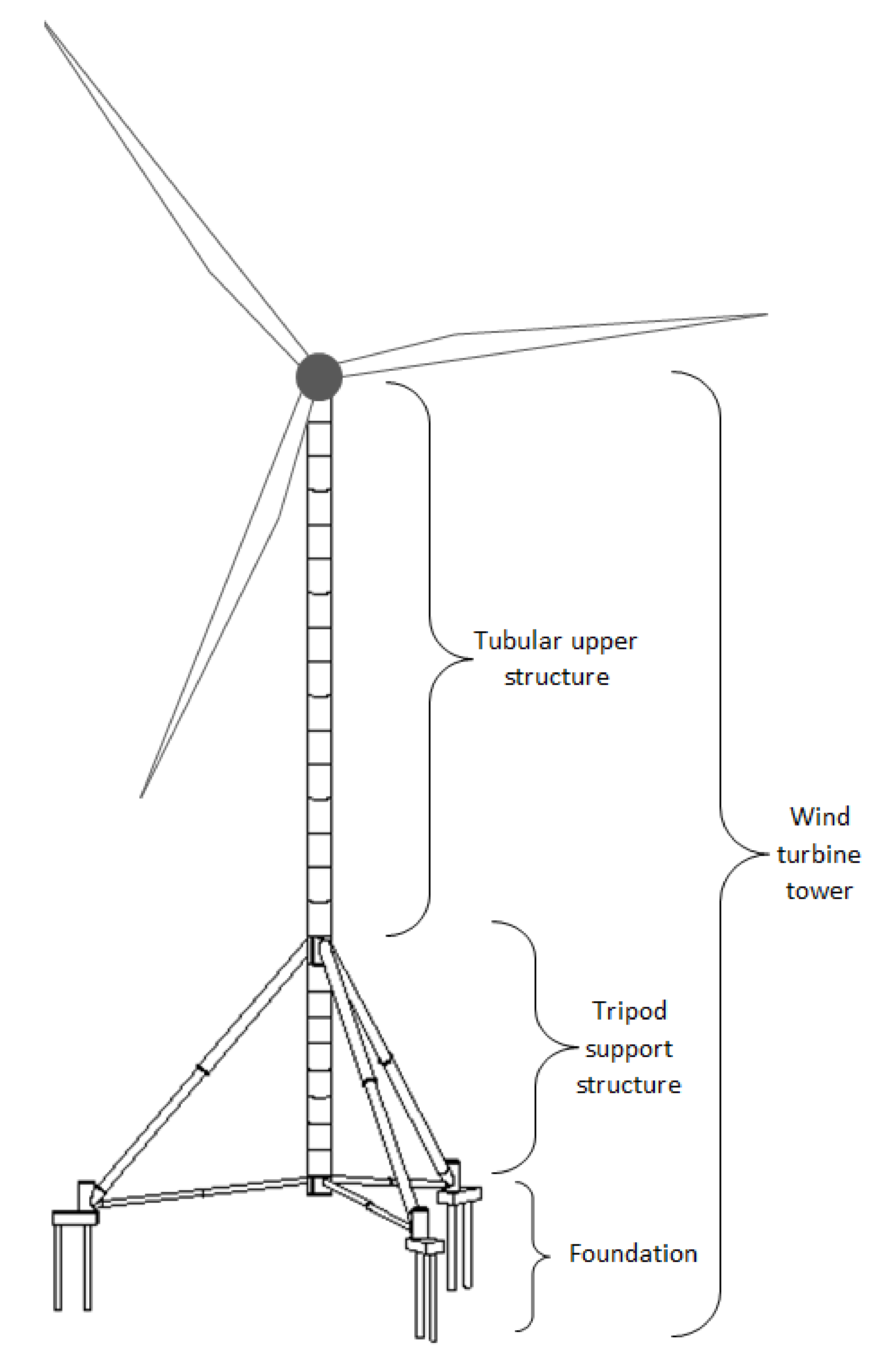
The proposed wind turbine tower assembly consists of a conventional tubular steel upper structure carrying a horizontal axis wind turbine and an adaptable lower support structure in the form of a tripod and its foundation (Figure 1). The tripod support structure comprises a tubular vertical leg that is coaxial with the upper structure to be supported and three sets of tubular upper and lower inclined legs, arranged in pairs around the vertical leg. Each inclined leg descends from the vertical leg to the ground level, where each upper and the corresponding lower leg meet at a corner junction piece that is connected to a set of foundation piles through a pile cap. The foundation level may be the same for all pairs of upper and lower inclined legs in cases of essentially flat terrains, or it may be different to adapt to the ground level in cases of inclined or rough terrains.
The upper structure may be any existing or future tubular tower consisting of individual cylindrical or conical cans with overall dimensions and shell thickness, depending on the mechanical/structural requirements, as well as fabrication and transportation constraints, as described in the introduction. Such cans are commonly fabricated by cold curving of flat plates and subsequent longitudinal welding. Individual cans may be welded to adjacent cans in the factory in order to form longer, pre-welded upper structure sections, having lengths that depend on the transportation constraints. At their ends, the upper structure sections are fitted with ring flanges for enabling their connection to adjacent sections. Such sections are lifted on-site by cranes and connected to adjacent parts by prestressed bolts. The connection of the upper structure to the underlying support structure may be realized in a similar manner. Appropriate platforms will be provided where necessary to facilitate initial bolting and subsequent maintenance.
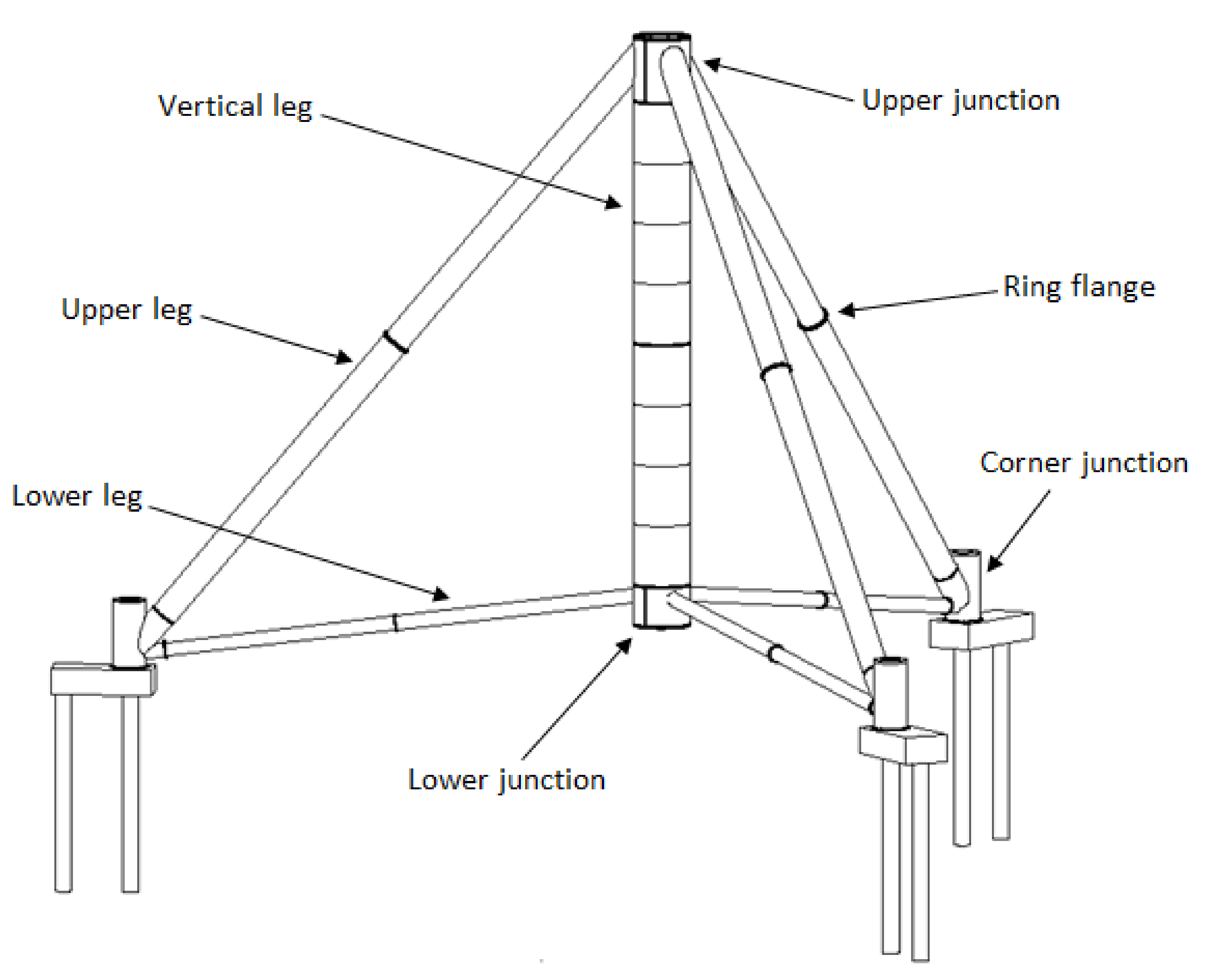
The tripod support structure consists of one vertical leg and three pairs of upper and lower inclined legs (Figure 2). Alternatively, the number of pairs may be different, leading to a multi-pod arrangement. This approach substantially enlarges the perimeter of support points of the tower on the ground, thus increasing the stability against overturning. Moreover, the support structure resists the large developing overturning moments primarily by axial action, thus exploiting material much better and requiring significantly smaller sections for the legs than the cantilevering upper structure and the tripod’s vertical leg, which operate flexurally.
The vertical leg is tubular, similar to the upper structure and consisting of individual cans of varying thickness to adjust to the needs imposed by developing mechanical actions, thus requiring gradually smaller thickness from top to bottom. Individual cans are also welded to adjacent cans in the factory in order to form longer, vertical leg sections, having lengths that depend on the transportation constraints. At their ends, the vertical leg sections are fitted with ring flanges for enabling their connection to other adjacent vertical leg sections, as well as to the upper junction piece at the intersection of the vertical leg and upper inclined legs and the lower junction piece at the intersection of the vertical leg and lower inclined legs.
The vertical leg is fitted with internal equipment, such as ladders, platforms, elevators, cabling and everything else that is needed for the wind turbine operation. It is not structurally necessary to have a foundation below the vertical leg; therefore, its bottom may be a few meters above the ground. This makes it possible to provide a manhole at the bottom of the vertical leg to enable entrance and exit of personnel and equipment. Thus, the commonly used side opening of tubular towers, requiring a heavy and costly frame stiffener of complex shape, can be avoided.
Each upper or lower inclined leg will have a circular hollow steel section that may be fabricated by cold curving flat plates, similar to the vertical leg, or alternatively, employ commercially available tubes for easier procurement. Considering that the mechanical action of inclined legs is primarily axial, with substantial flexural action developing only near the ends, a constant tube thickness over most of their length will be cost-effective, with possible thickness increase near the ends. Avoiding the need for gradually varying thickness, combined with relatively small diameter requirements because of the primarily axial function, permits to adopt long tube pieces, thus minimizing the needs for welding and bolting and allowing significant fabrication time and cost reduction. Section lengths are dictated by transportation constraints, and individual sections are connected together on-site through ring flanges and prestressed bolts.
Depending on the diameter and the location, ring flanges may be either internal or external, considering the accessibility for bolting during erection and for subsequent maintenance. External ring flanges and accompanying bolts may require additional protection against corrosion and environmental factors. In case of internal ring flanges and depending on the inclination of the legs, internal ladders may be necessary to allow access of personnel for bolting and maintenance. In the case of external ring flanges, bolting and maintenance may be carried out using telescoping boom lifts or scissor lifts.
2.2. Connection Details
The upper junction piece between vertical leg and upper inclined legs, the lower junction piece between vertical leg and lower inclined legs, as well as the corner junction pieces between upper inclined legs, lower inclined legs and the foundation, are very important for the successful realization of this concept. High stress concentrations are encountered at these locations. In general, such stress concentrations may be addressed either by local shell wall thickening or by arrangement of internal stiffeners or by a combination of the two. Further considerations to be taken into account are, among others, (i) to provide openings for access into the inclined legs for bolt tightening and maintenance purposes, (ii) to respect fabrication limitations related to maximum plate thickness that can be cold-curved, (iii) to minimize weld lengths for cost reductions and (iv) to respect the size limitations for transportation, which may be different for onshore and offshore transportation and also depend on the specific factory and site locations and the alternative itineraries between them. To that effect, different alternatives for these special junction pieces are proposed.
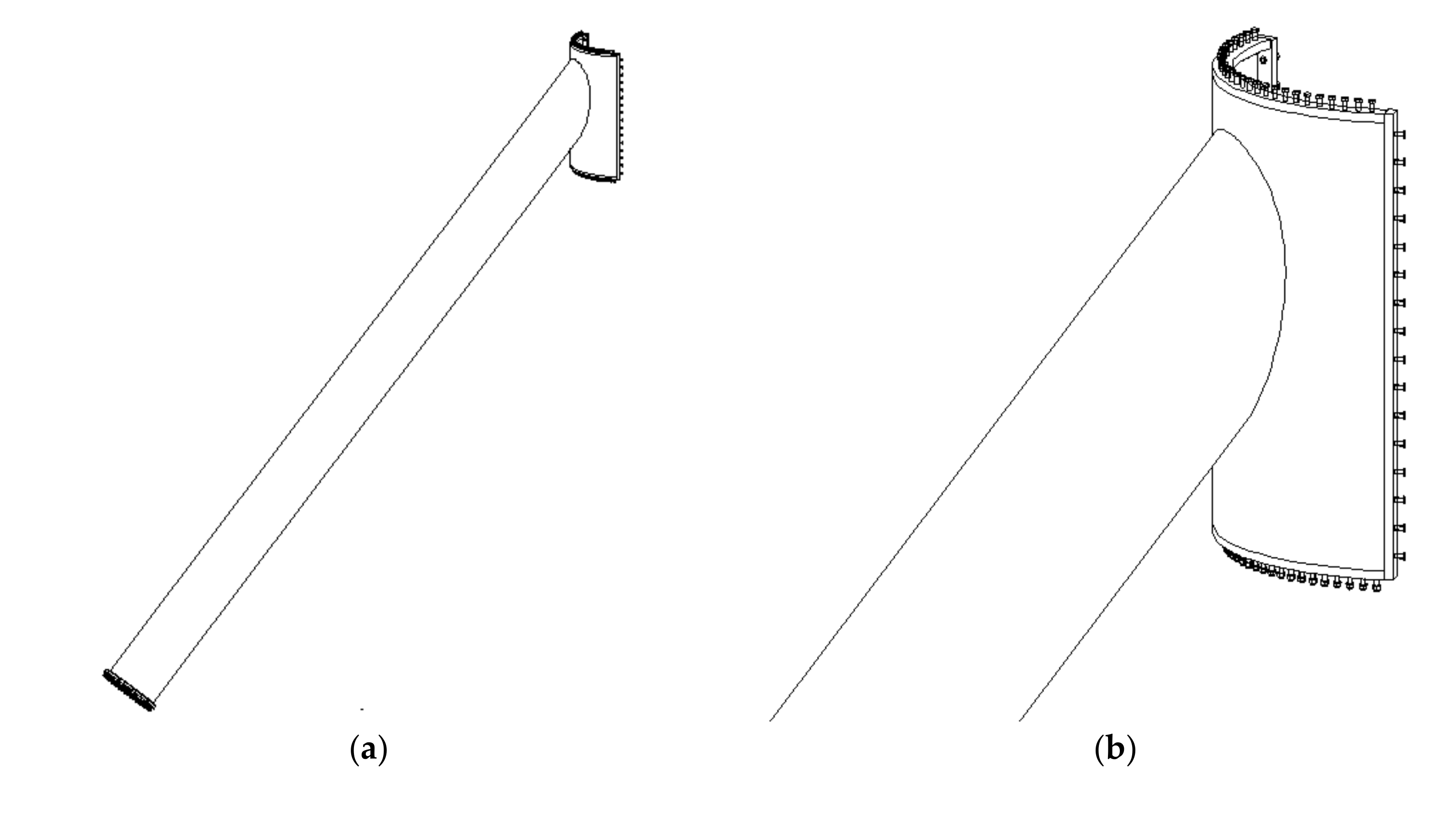
Considering the transportation restrictions, a segmental upper junction piece is proposed, of which one segment is shown in Figure 3. It is part of a cylinder corresponding to one-third of the cylinder’s circumference, thus having a central angle of 120°. This segment is welded in the factory to the top end of one upper inclined leg. At its two vertical edges, this segment features two welded vertical end plates, arranged in the radial direction, through which it is bolted on-site to similar end plates of the adjoining segments of the upper junction piece, thus forming a full cylindrical piece. At its upper edge, each segment features a welded partial ring flange, also only 120° at the central angle. After the three segments are bolted together via the vertical end plates, their three partial ring flanges form a full 360° circular ring flange through which this segmental upper part of the vertical leg is bolted to the ring flange welded at the bottom of the upper structure. Similarly, at its lower edge, each segment of the upper junction piece also features a welded partial ring flange through which it is bolted to the ring flange welded at the top of the below part of the vertical leg.
The segment of the upper junction piece may be fitted with internal ring and vertical stiffeners. The number of stiffeners may vary, depending on the need to address local stress concentrations, resulting from detailed finite element analyses of this area. In this case, access into the upper inclined leg through a manhole is not provided. In case such access is necessary, the locations of stiffeners must consider the location and dimensions of the manhole, and some of the stiffeners may also act as peripheral frame for the manhole. Alternative to the use of stiffeners, the local stress concentrations can be addressed by a higher plate thickness.
Considering the relatively small size of segment of the upper junction piece, the upper section of the upper leg to which it is welded may be of significant length (Figure 3a), still allowing onshore transportation by trucks. Thus, there is no need for a ring flange of the upper leg near the upper junction. The ring flange can be located at the bottom of the upper section of the upper leg, thus reducing the overall number of ring flanges along each upper leg. Access to the intermediate ring flanges from the interior of the upper legs is more difficult due to the longer distance; thus, external ring flanges may be preferable, accessible for bolting and maintained with the use of telescoping boom lifts or scissor lifts. In general, the upper leg may comprise a varying number of cans to accommodate the desirable variation of thickness in order to adjust to developing mechanical actions, connected to neighboring cans either by welding or through ring flanges at their ends. The number of cans depends also on cost considerations in balancing weight optimization and weld length minimization.
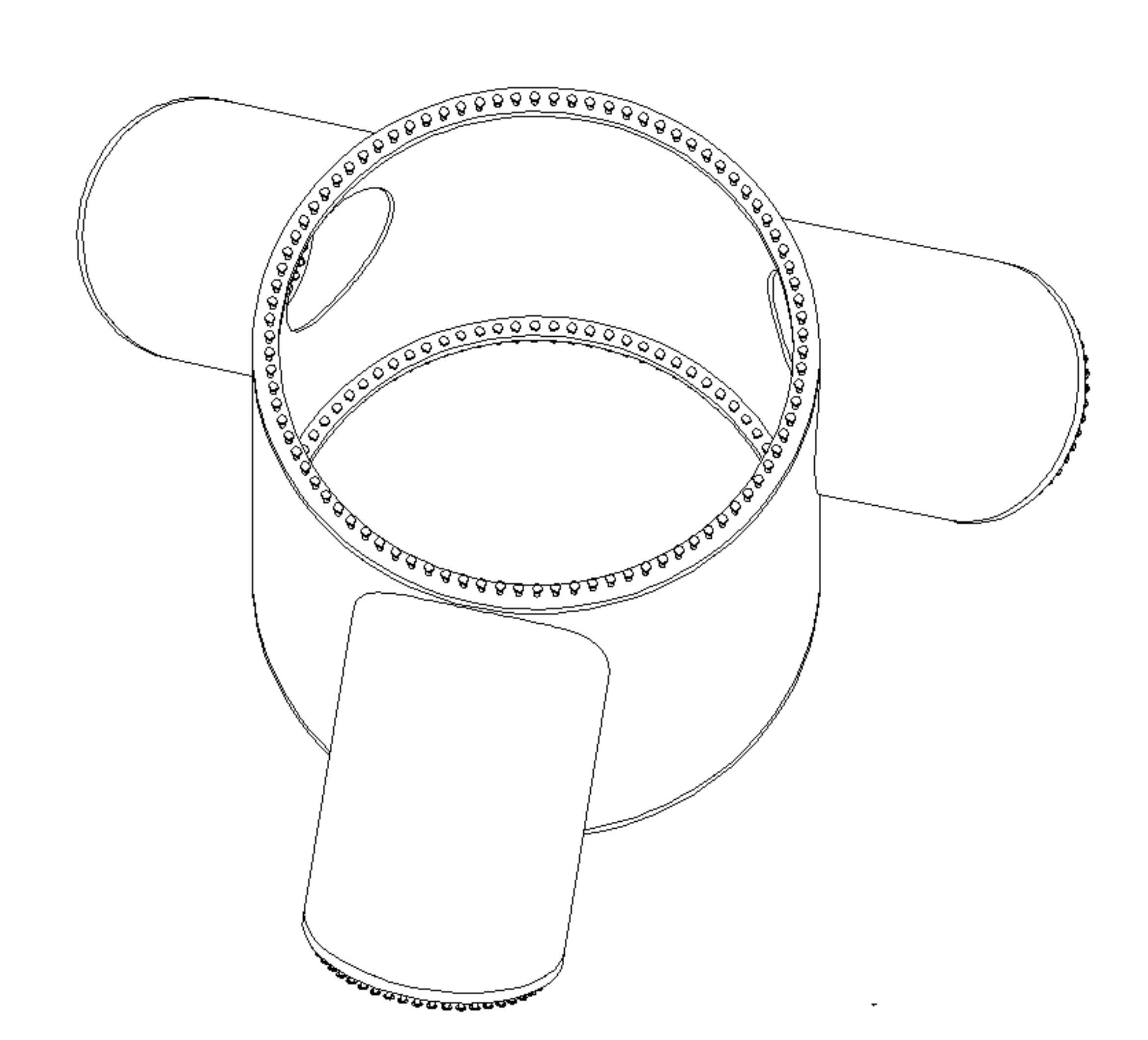
Alternatively, a unified upper junction piece between vertical leg and upper legs may be realized, as shown in Figure 4. It comprises the upper can of the vertical leg and the upper cans of the upper inclined legs welded together in the factory and transported as one assembly.
The diameter of the upper can of the vertical leg is dictated by the diameter of the bottom part of the upper structure, as the two must be connected together. This connection is also realized by means of two ring flanges, one welded at the top of the upper can of the vertical leg and the other welded at the bottom of the upper structure, with the ring flanges bolted together by prestressed bolts. A similar ring flange is provided at the bottom of the upper can of the vertical leg to enable the connection to the below part of the vertical leg. This upper can of the vertical leg will also be fitted with internal equipment, such as ladders, platforms, elevators, cabling and everything else that is needed for the wind turbine operation; thus, any stiffeners that may be necessary must take this into consideration.
The upper cans of the upper inclined legs are then pre-welded in the factory to the upper can of the vertical leg. At its bottom end, each upper can of the upper inclined leg is fitted with a ring flange to connect to the adjacent part of the upper leg. Depending on the diameter of the upper leg, this flange may be internal, if access for initial bolting and subsequent maintenance is possible, or external otherwise. In the example of Figure 4, the ring flange is internal; therefore, manholes are provided on the shell wall of the upper can of the vertical leg, centrally located with respect to each upper leg, of sufficient size to enable access to personnel and equipment. Moreover, the upper inclined leg will be provided with a ladder and platforms, as needed.
In the example of Figure 4, the high local stress concentrations in the upper can of the vertical leg and upper can of the upper inclined leg are addressed by means of sufficiently high shell thickness, without any stiffeners. Alternatively, smaller shell thickness may be adopted, compensated by stiffeners. Due to the welding cost, it is likely that higher thickness without stiffeners will be preferable, as long as it is feasible to curve plates of that thickness.
The overall dimensions of this unified upper junction piece are critical for the realization of this alternative. Considering that the external diameter of the upper can of the vertical leg is dictated by the diameter of the bottom part of the upper structure, it is likely that this diameter will already be near the transportation limitations. Considering also the three protruding upper cans of upper inclined legs, special transportation solutions may be necessary. In case the transportation limitations cannot be overcome, the first alternative of a segmental upper junction piece composed of multiple segments of upper junction piece, as has been described above, may be preferable.
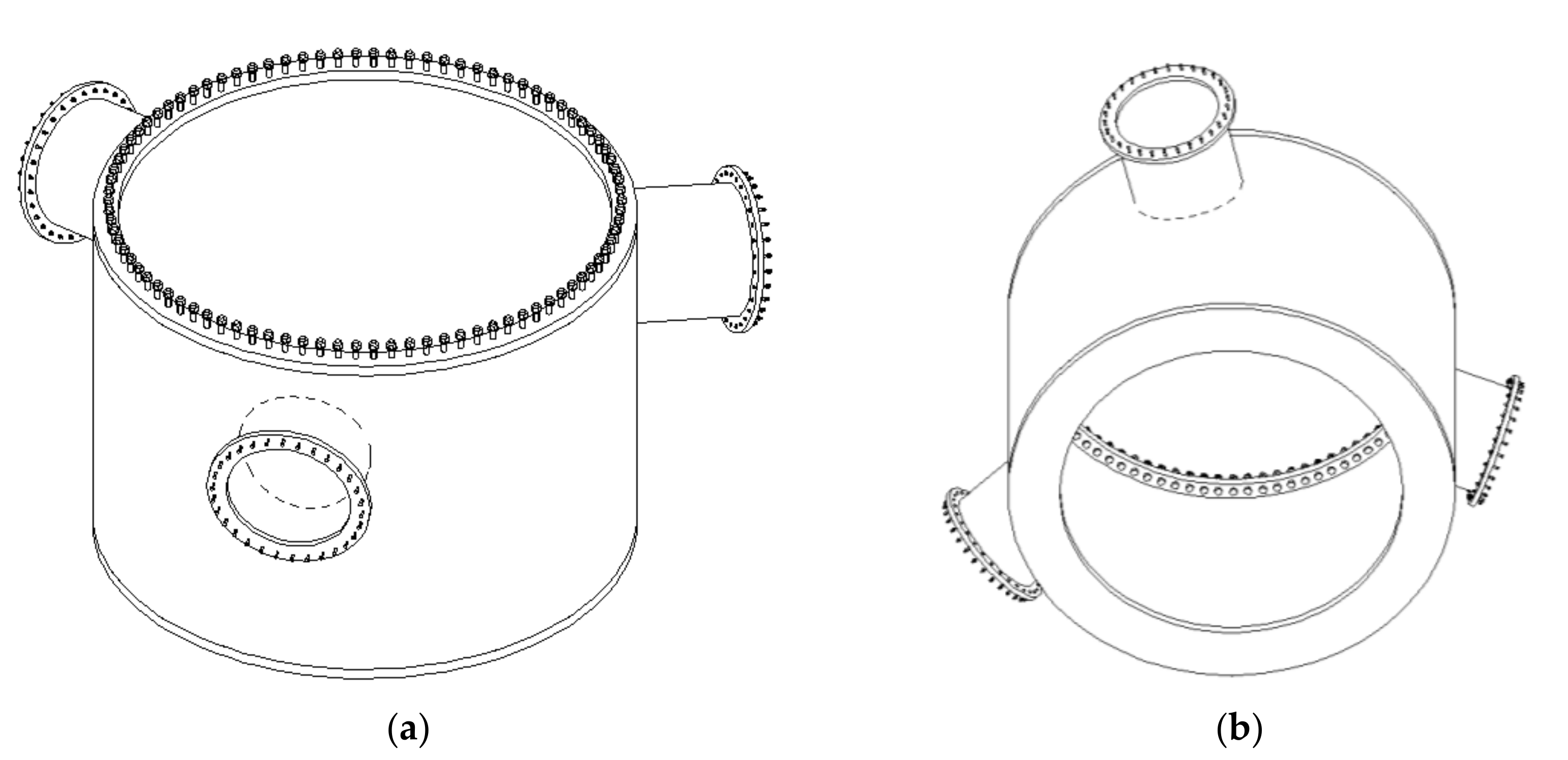
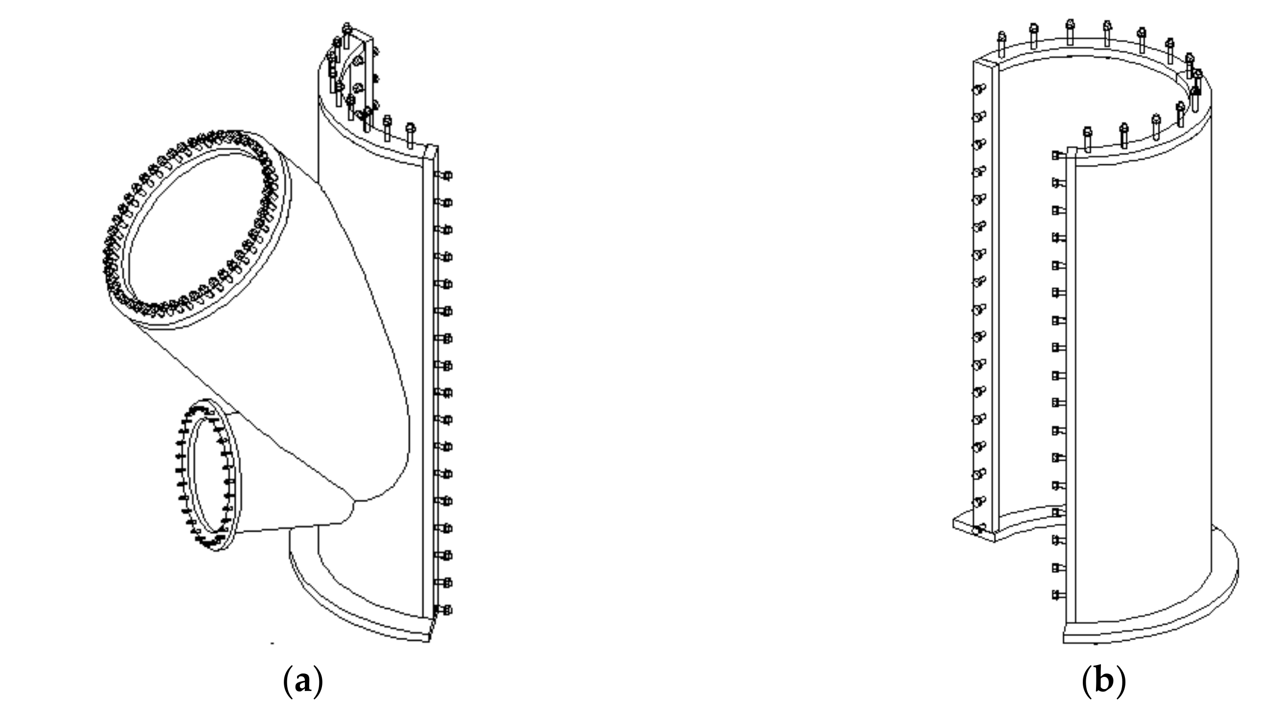
Regarding the lower junction piece between vertical leg and lower legs, it can also be configured either as segmental or as unified, similar to the upper junction piece. Due to the relatively small actions of the lower inclined legs, the diameter requirements will, in most cases, be smaller than in the upper legs, potentially making the unified solution (Figure 5) more feasible from a transportation point of view. This can be further facilitated considering the reduced actions on the vertical leg towards its bottom, making a conical arrangement possible and yielding a smaller diameter of the lower can of the vertical leg, thus facilitating transportation of the entire lower junction piece in spite of the protruding inner cans of lower inclined legs. Moreover, external ring flanges between adjacent sections of lower legs are more likely, promoted also by the lower height over the ground, which facilitates external access for bolting and maintenance. In such case, no manholes are necessary on the shell wall of the lower can of the vertical leg. At the bottom, an appropriate conventional stiffening ring is provided around the perimeter, still allowing enough space in between for the manhole (Figure 5b).
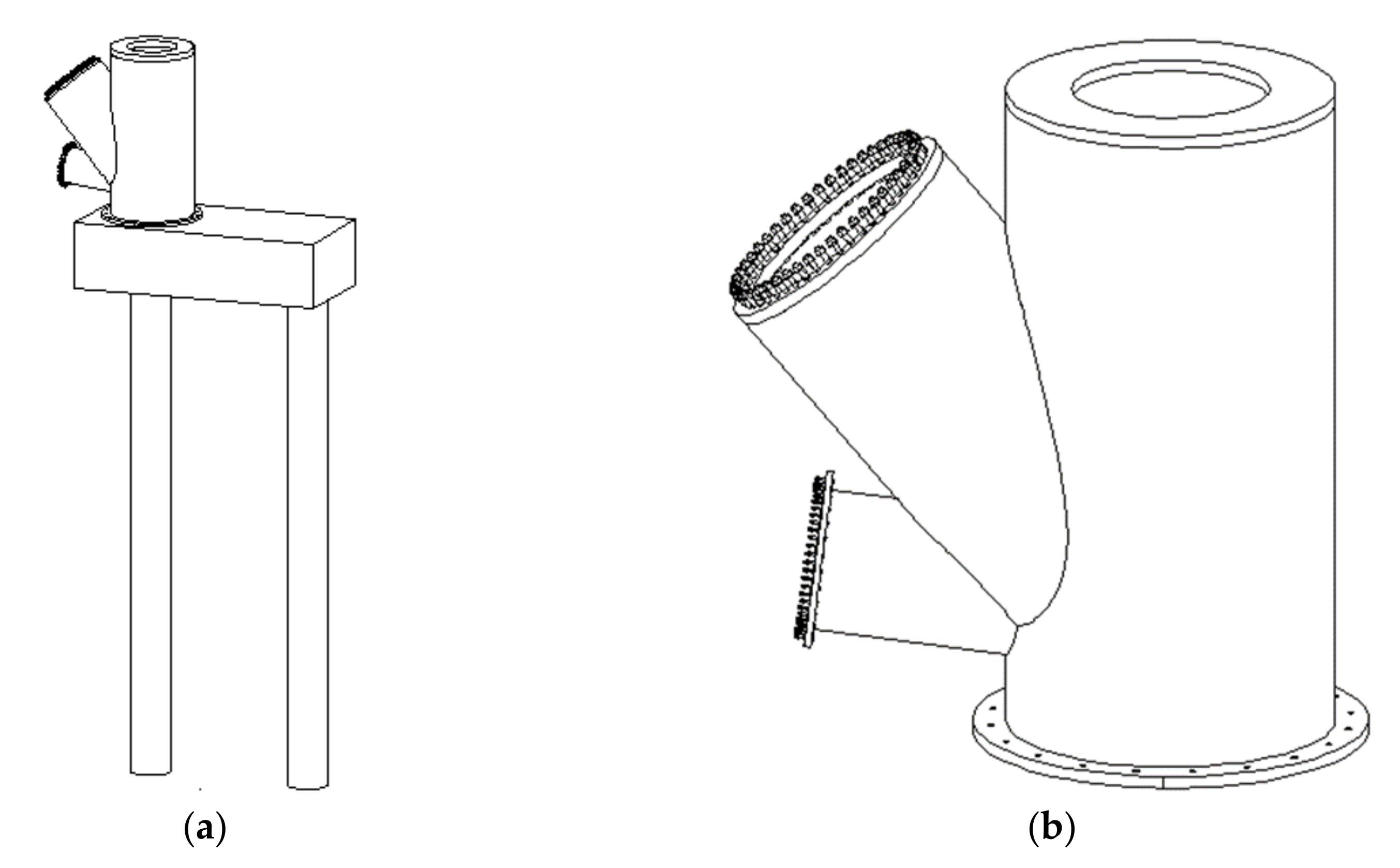
In Figure 6, a unified corner junction piece between one upper leg and the corresponding lower leg is presented. In order to accommodate this junction, a short, vertical auxiliary tube is also provided. These three pieces are welded together in the factory and transported as one assembly. The connections to the adjoining sections of upper and lower inclined legs are again realized by means of ring flanges and prestressed bolts. The ring flanges may again be external or internal, but considering that they are very near the ground, external ring flanges are likely to be preferable. At the bottom of the auxiliary tube, another ring flange is provided for the anchor bolts to ensure a connection to the foundation. The ring flange and anchor bolts may be external, internal or both, as dictated by the strength requirements.
At the top of the auxiliary tube, local strengthening by a ring-shaped stiffener is provided, allowing sufficient space for a manhole and providing entrance and exit to personnel and equipment in case internal bolts are used either at the ring flanges of the inclined legs or for the anchoring of the bottom of the auxiliary tube into the foundation. Alternatively, in case no access into the auxiliary tube is needed, a welded lid may be provided at its top, acting as a stiffener. The stress concentrations of shells in this junction may also be addressed either by means of sufficiently high shell thicknesses without any stiffeners or smaller shell thicknesses may be adopted, compensated by stiffeners.
The overall dimensions of this unified corner junction piece are critical for the realization of this alternative. The diameter of the auxiliary tube will have to be somewhat larger than the larger among the two diameters of upper and lower inclined leg for better welding between the three tubes, and this will ultimately dictate the overall dimensions of the unified corner junction piece. In case transportation of the entire corner junction piece is not possible, the segmental corner junction piece shown in Figure 7 may be adopted.
A cylindrical first segment of the auxiliary tube of this segmental corner junction piece is welded to the bottom cans of the upper and lower inclined legs. It has the same height as the auxiliary tube of the unified foundation junction piece but a smaller central angle, dictated by the need to accommodate the welds of the two bottom cans. At its two vertical edges, this piece has radial, vertical end plates used to connect it via prestressed bolts to the corresponding radial vertical end plates of another second cylindrical segment of the auxiliary tube. The two segments complement each other to form a full cylinder.
Along their low edges, the two segments feature welded partial ring flanges similar to the lower ring flange of the unified foundation junction piece, through which anchor bolts are provided to connect to the foundation concrete. Similarly, at their upper edge, the two segments feature welded partial ring flanges that are bolted to a common ring stiffener, allowing sufficient space for a manhole for entrance and the exit of personnel and equipment. In case no access into the auxiliary tube is needed, a circular lid may be bolted to the two partial ring flanges, acting also as a stiffener.
2.3. Foundation Layout
Separate pile foundations of each corner junction piece are foreseen consisting of reinforced concrete piles interconnected by a reinforced concrete pile cap at their top. The number, diameter, depth of embedment and reinforcement of the piles depend on the soil conditions and on the actions transferred to the foundation by the superstructure. In the example of Figure 6a, two piles are arranged in radial direction to resist the applied reaction forces more effectively. The inner pile, developing tension due the horizontal reaction force directed radially outwards, is placed closer to or directly below the auxiliary tube in order to counterbalance some of this tension by the vertical reaction component. Moreover, in this arrangement, the vertical reaction is transferred directly to the pile without causing bending in the pile cap. Alternatively, other pile numbers and arrangements may be adopted, but the above guiding principles will ensure an optimized foundation design.
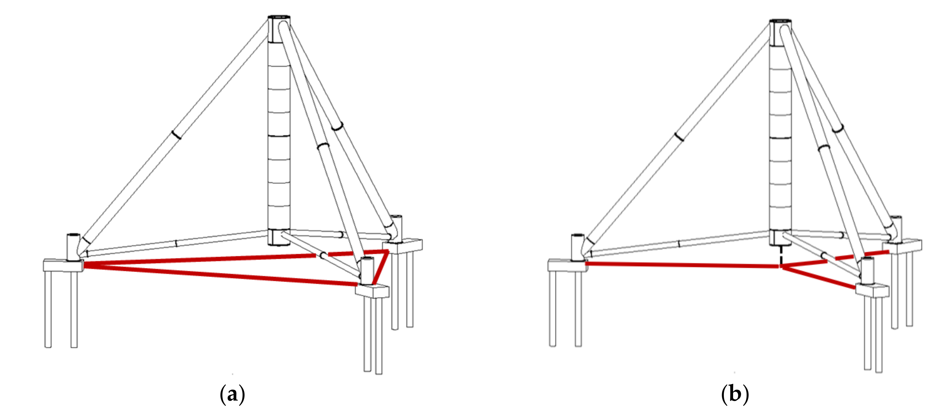
In cases of poor soil conditions, pile caps of each pair of upper and lower inclined legs may be connected to each other above or belowground by tie rods (Figure 8), arranged either directly between individual pile caps or oriented radially and connected to each other below the vertical leg in a radial, star-shaped arrangement in order to better resist the applied horizontal reactions without compromising the overall stiffness of the tower to lateral loads.
2.4. Erection Methodology
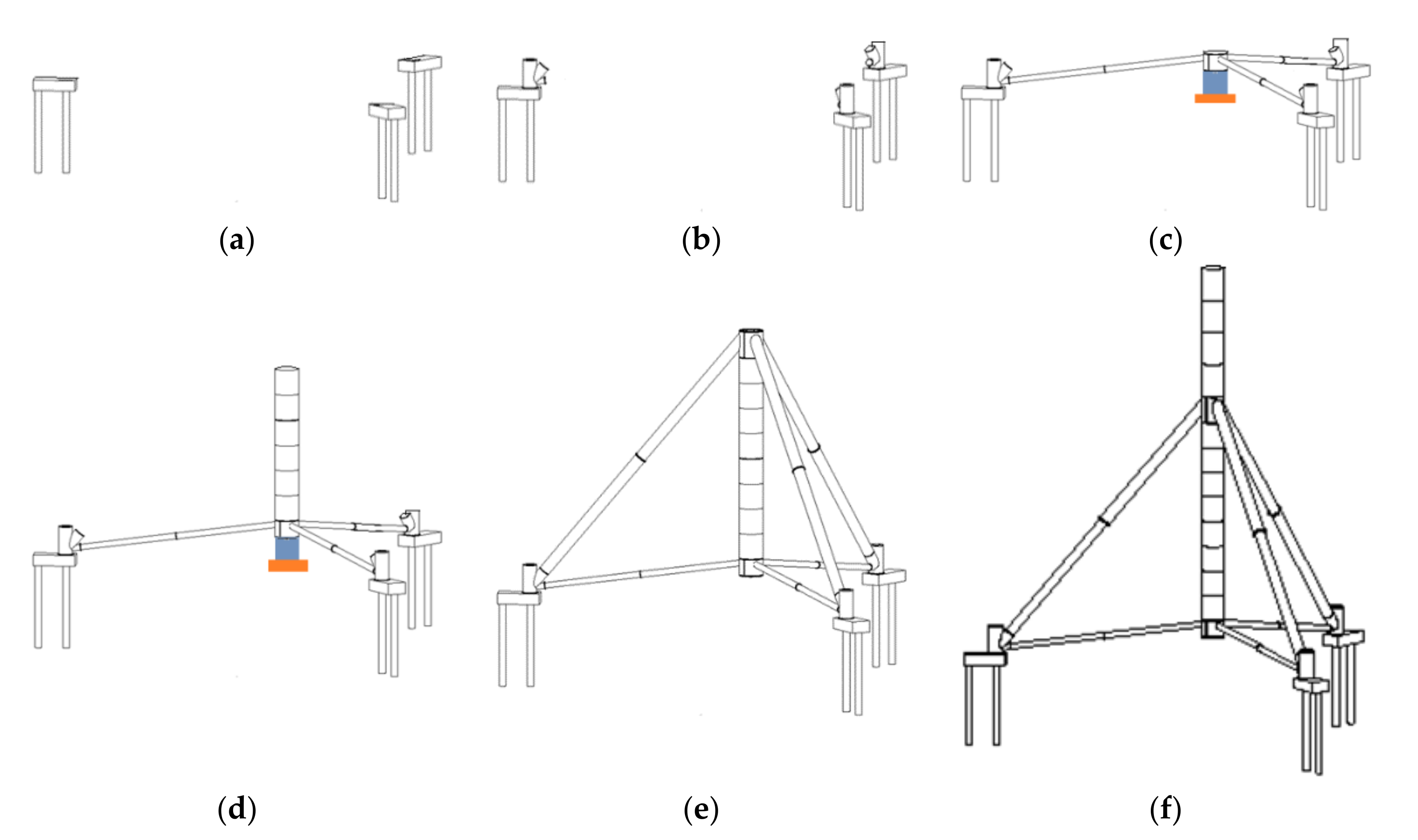
A methodology for the erection of the proposed wind turbine tower assembly may consist of the steps listed below and is schematically illustrated in Figure 9:
- The foundation is constructed using conventional pile boring machines;
- The corner junction pieces are anchored onto the corresponding individual foundations;
- The lower inclined legs are assembled on the ground by bolting together their constituent parts;
- A temporary support structure is erected below the intended location of the vertical leg, comprising a temporary foundation and a temporary scaffolding/truss system reaching from the ground to the bottom level of the vertical leg equipped with jacks to control its vertical position. A mat type of a temporary foundation consisting of a grid of steel beams is proposed, so that it is transportable and reusable;
- The unified lower junction piece is lifted from the ground by means of cranes and placed securely on the temporary support structure;
- The lower inclined legs are lifted from the ground by means of cranes and connected at their inner end to the lower junction piece and, at their outer end, to the corner junction pieces. Upon completion of this process for all lower legs and fixing of the bolts, the system becomes laterally stable. Vertical stability may not be secured yet due to the small inclination of the lower legs; thus, the temporary support structure is retained in place;
- Alternative to the two above steps, in the case of segmental lower junction pieces, the erection and assembly of lower junction piece and lower legs takes place simultaneously;
- Successive sections of the vertical leg, from bottom to top, are lifted from the ground by means of cranes and bolted together. This is continued until the unified upper junction piece is erected. Up to that point, the vertical leg acts in a cantilever manner. If necessary, its lateral stability is ensured by temporary supports;
- The upper inclined legs are assembled on the ground by bolting together their constituent parts;
- The upper inclined legs are lifted from the ground by means of cranes and connected at their inner/top end to the upper junction piece and at their outer/bottom end to the corner junction pieces. Upon completion of this process for all upper legs and fixing of the bolts, the system becomes vertically and laterally stable;
- Alternatively, in case of segmental upper junction pieces, the erection and assembly of upper junction piece and upper inclined legs takes place simultaneously;
- The temporary support structure below the vertical leg and its temporary foundation are removed by relaxing the jacks. They are moved to the next location and are used for the erection of the next wind turbine tower assembly;
- The lower part of the upper structure is lifted from the ground by means of cranes and bolted at the top of the upper junction piece;
- Successive sections of the upper structure, from bottom to top, are lifted from the ground by means of cranes and bolted together, as in conventional tubular wind turbine towers. The upper structure acts in a cantilever manner, for which it has been properly designed;
- The nacelle, rotor and blades are lifted from the ground by means of cranes and are put in place, as in conventional tubular wind turbine towers.
3. Results
In order to verify the feasibility and cost-effectiveness of the proposed tripod substructure, a specific case study has been investigated at preliminary structural design level. The assumed data, modeling and analysis approach and main findings are summarized in this section.
3.1. Geometry, Cross-Sections and Material Properties
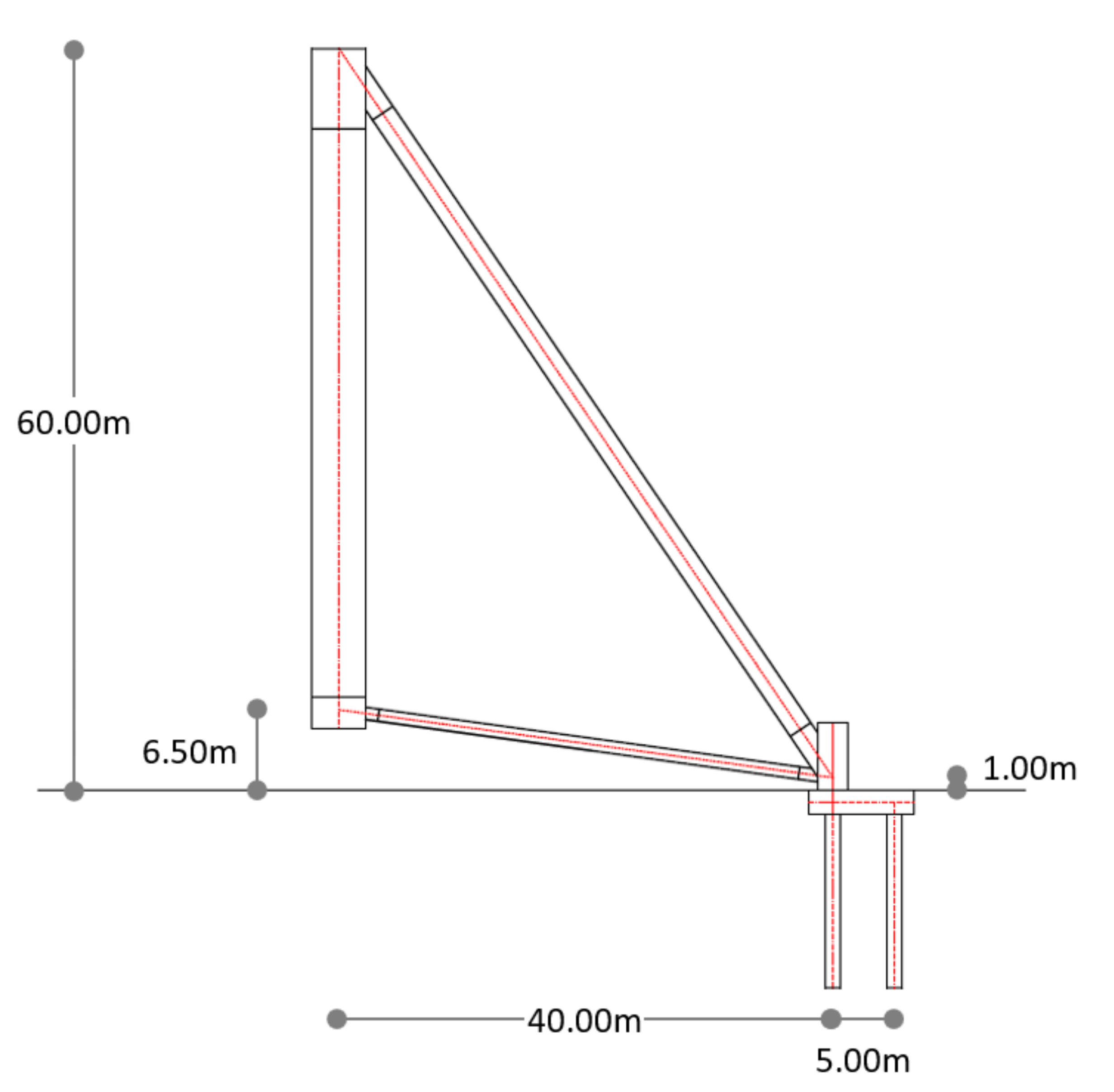
The geometry of the examined case study is illustrated in Figure 10, comprising a tripod substructure with an overall height over the ground equal to 60 m and a base radius equal to 40 m. The vertical leg has a constant diameter of 4300 mm and thickness comprising 60 mm and 30 mm in the upper and lower junction pieces, respectively, and varying in between, from 40 mm at the top to 18 mm at the bottom, with a step of 1 mm every 2000 mm. The upper inclined legs have a diameter of 2000 mm and a wall thickness of 20 mm, locally increased to 40 mm at the two ends, while the lower legs have a diameter of 1000 mm and a wall thickness of 10 mm, locally increased to 25 mm at the two ends.
The auxiliary corner tubes have a diameter of 2500 mm and a thickness of 30 mm and are anchored on 3-m-wide, 8.5-m-long and 2-m-thick reinforced concrete pile caps that connect two reinforced concrete piles with 1 m diameter each arranged in the radial direction at a distance of 5 m from each other. The piles embedment depth depends on the soil and is assumed herein to be equal to 15 m. The steel superstructure is made of S355 grade steel, while concrete foundation comprises C25/30 concrete and B500S reinforcing steel.
3.2. Soil Conditions
For reasons of simplicity, an intermediate over consolidated clay has been assumed, having an undrained shear strength cu = 50 kN/m2. A stiff soil has been considered on purpose in order to better study the structural properties of the tripod on the overall structural response, with little influence from the soil–foundation interaction.
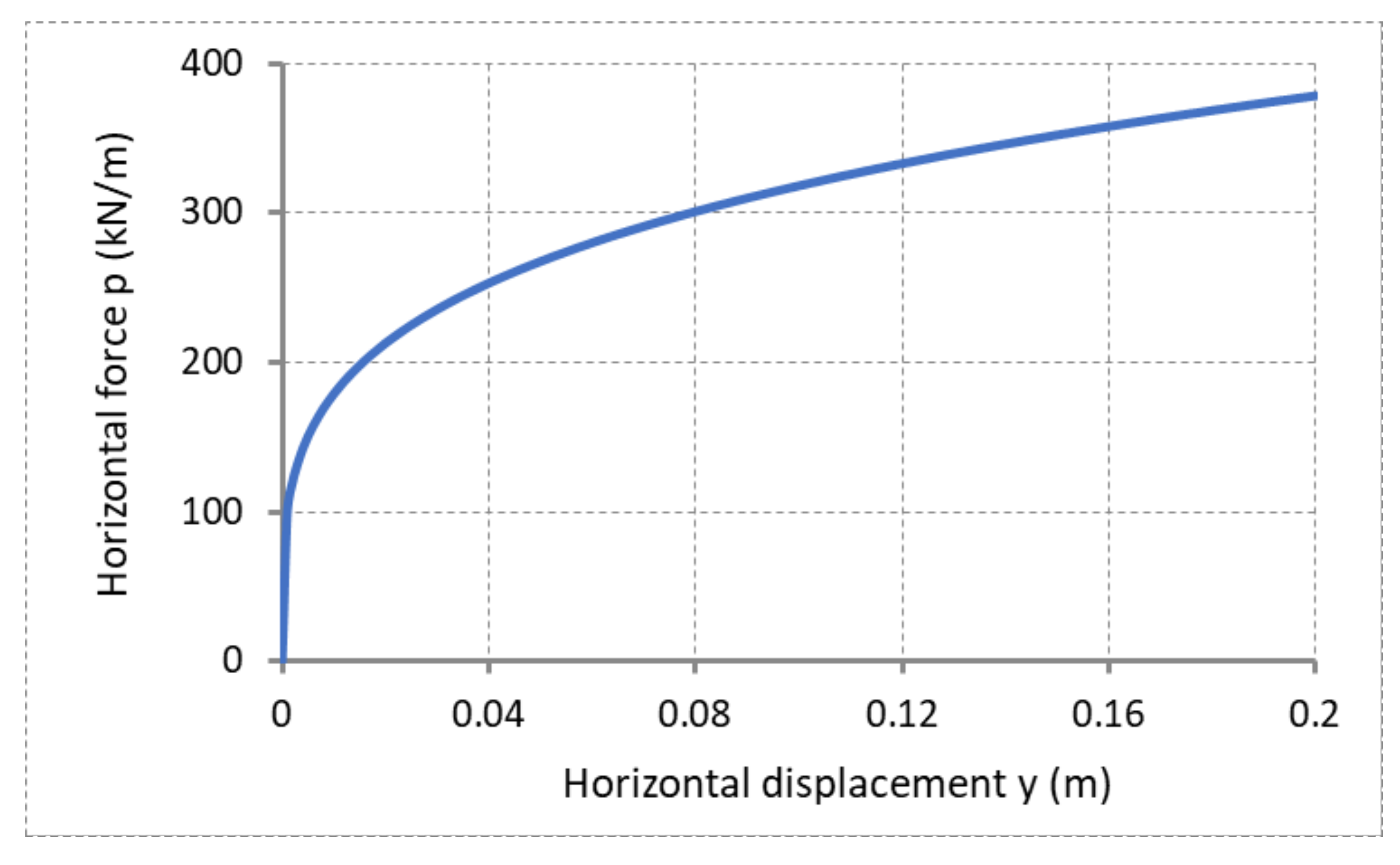
The soil–pile interaction is then modeled with nonlinear horizontal springs in the radial and tangential directions, spaced at 1 m and described by the horizontal force p vs. horizontal displacement y curves, which are constant over the height of the pile (Figure 11). Conservatively, the friction over the pile is neglected, and the entire pile resistance to vertical loads is considered as concentrated at the bottom via a rigid roller support.
3.3. Assumed Loading
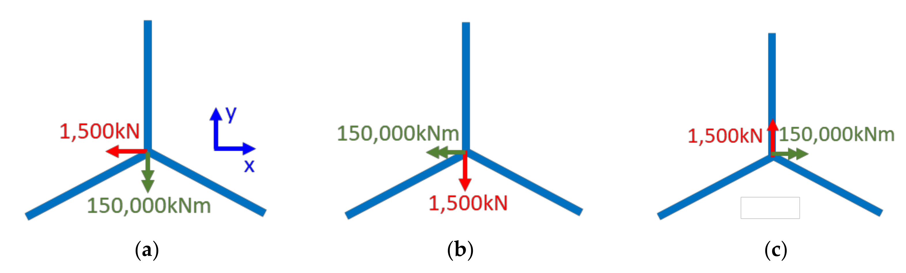
Typical values of support reactions of a 120-m-tall conventional tubular wind turbine tower with a 5-MW wind turbine installed at its top were applied on the top of the tripod, comprising a 10,000-kN vertical force, a 1500-kN horizontal force, a 150,000-kNm bending moment and a 5000-kNm torsional moment. These values were assumed to represent the design loads, including partial factors, and were extracted from maximum support reactions of actual towers with appropriate rounding off.
The vertical load is always directed downwards, while three different scenarios were considered for the horizontal load, and the bending moment is always considered to act in the same direction as the flexure induced by the horizontal load (Figure 12). The two axes in the horizontal plane are also indicated in order to relate the directions of the forces and moments to the subsequent analysis results. The self-weight of the tripod was also considered.
3.4. Structural Performance
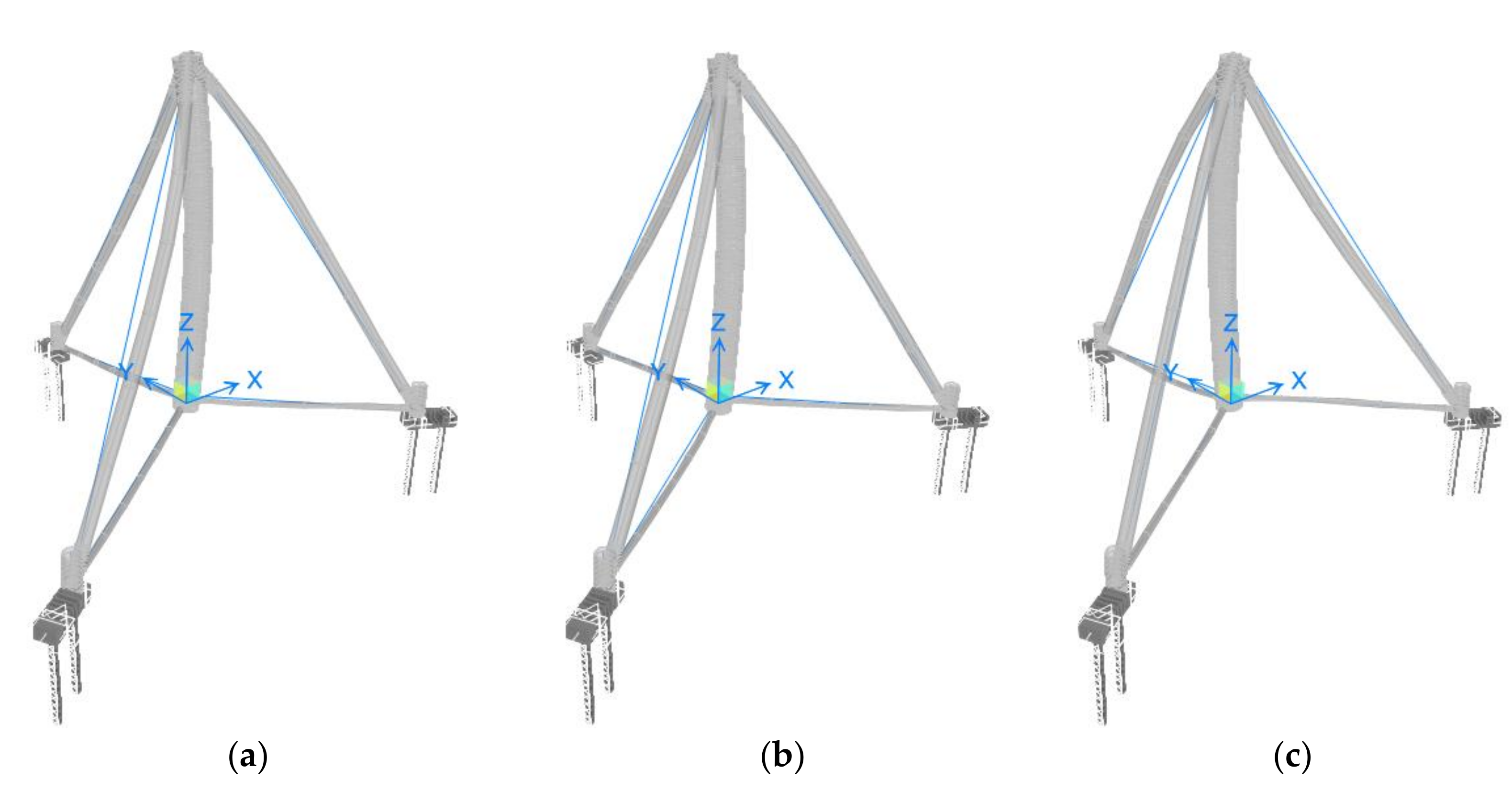
In order to study the overall performance of the tripod structure, a numerical model has been developed in SAP2000, comprising linear beam elements for all members of the steel superstructure and the reinforced concrete foundation, and nonlinear spring elements for the soil springs (Figure 13). The model has been subjected to the loads described in Section 3.3, applied at the tripod’s top.
Deformed shapes of the tripod structure obtained for the three load combinations of Section 3.3 are illustrated in Figure 14. The maximum observed lateral and vertical displacements at the top of the tripod are 30.8 mm and 29.8 mm from loading cases 1 and 3, respectively, while the maximum flexural and torsional rotations are 0.01 rad (= 0.56°) and 0.0042 rad (= 0.24°), respectively, both from loading case 1. They are partly due to the deformation of the superstructure and partly due to the deformation of the foundation, taking into account that, for the stiff assumed soil conditions, the maximum pile cap displacements in the radial direction are equal to 29.5 mm, while, in the circumferential direction, they are negligible.
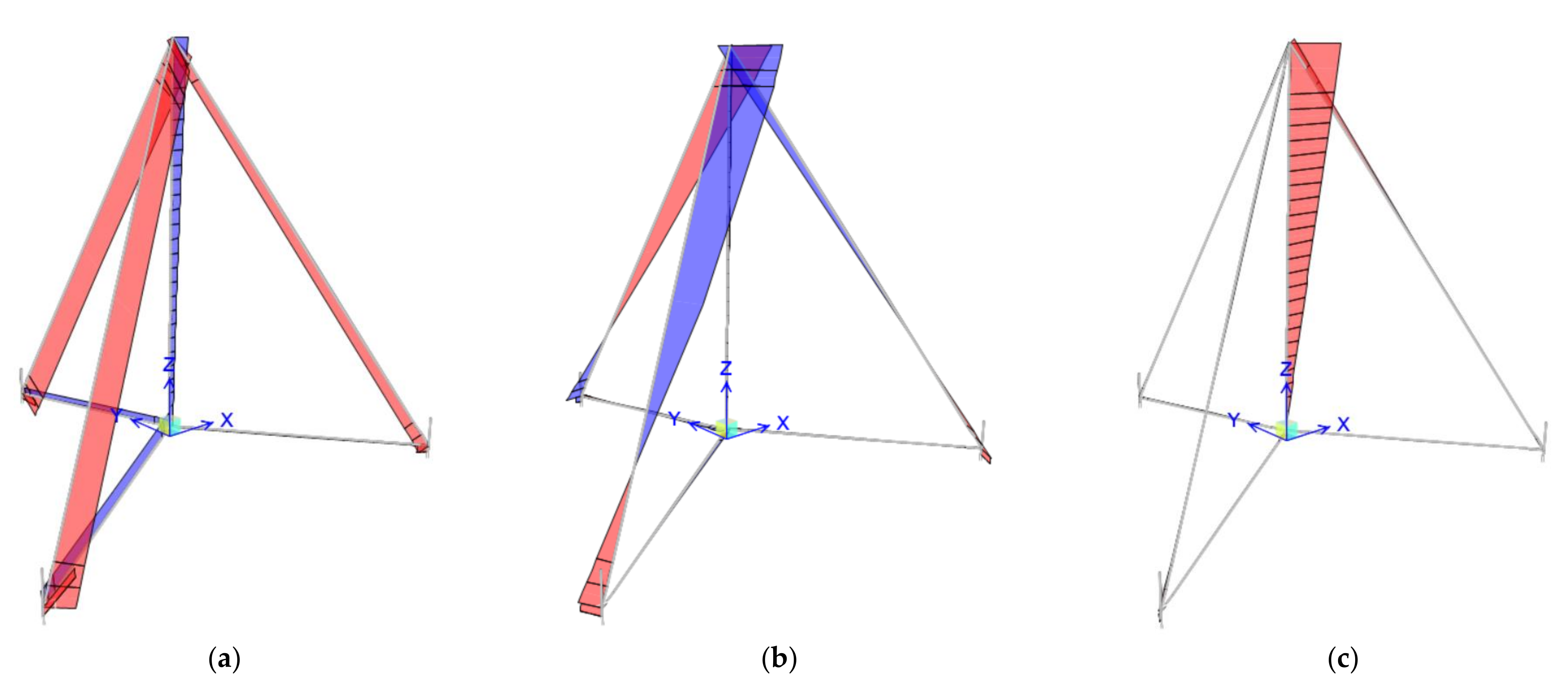
Illustrative axial force and bending moment diagrams of the steel superstructure due to loading scenario 1 are shown in Figure 15. Taking all three loading cases into account, the upper inclined legs have a maximum compressive axial force around 11,000 kN and a maximum resultant bending moment around 9300 kNm in the main part of the leg, increasing to 12,000 kNm in the thicker end piece. The corresponding quantities for the lower inclined legs are 2700 kN (tension) and 900 kNm (1250 kNm in the thicker end piece) and, for the vertical leg, 3350 kN (tension) and a 131,000-kNm bending moment at the top, diminishing to a very small value at the bottom.
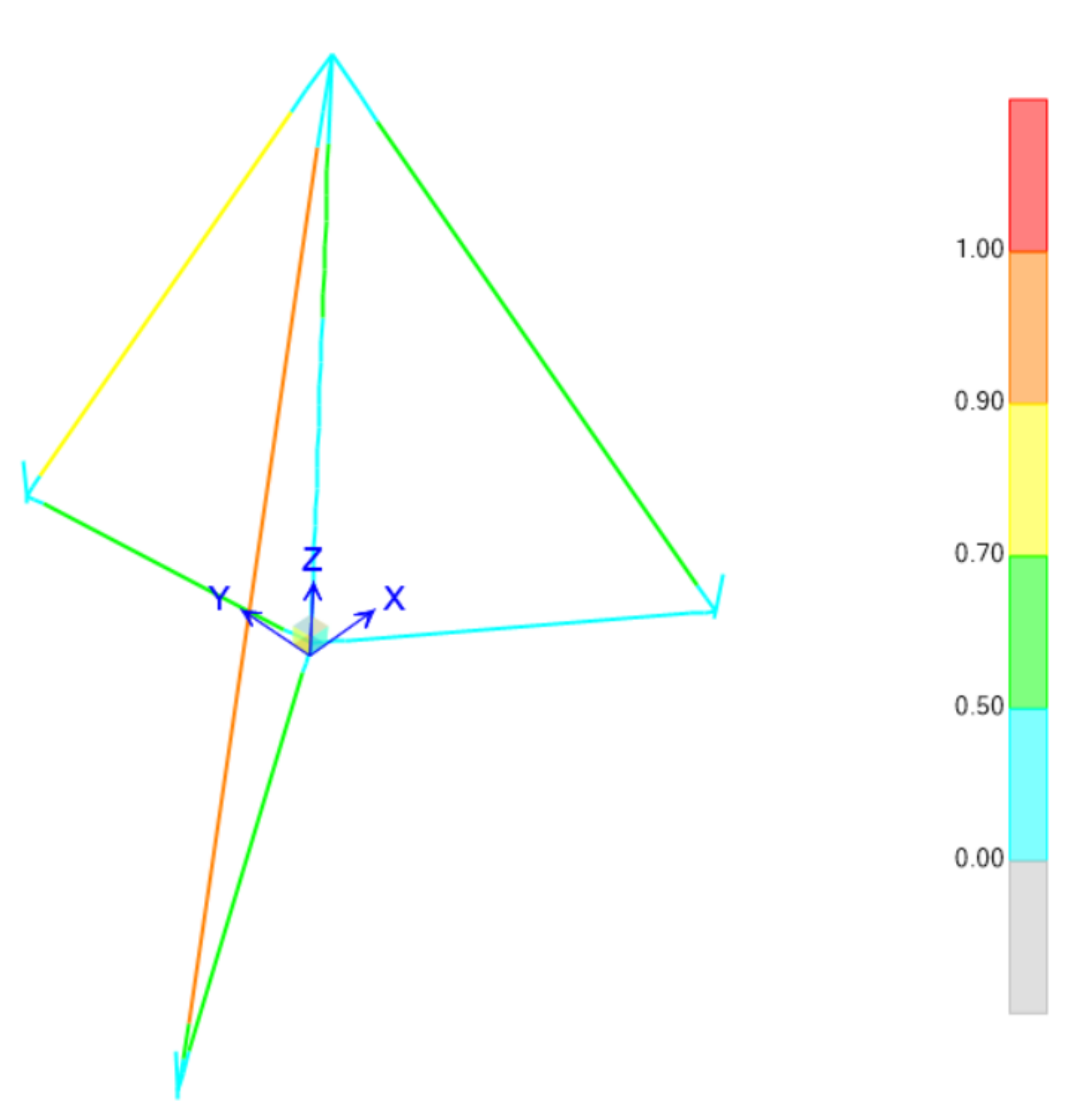
Design of the steel superstructure according to EN1993-1-1 leads to the utilization ratios shown in Figure 16. This verification assumes an elastic section design and takes global leg buckling into account but neglects the local buckling. For that reason, generous safety margins have been allowed. It is noted, however, that preliminary finite element analyses employing a dense shell element mesh for the tubular members and considering the material and geometric nonlinearity, as well as initial imperfections, have shown that, actually, a smaller leg thickness would have been sufficient to also cover the local buckling verification. These results are not shown here for brevity.
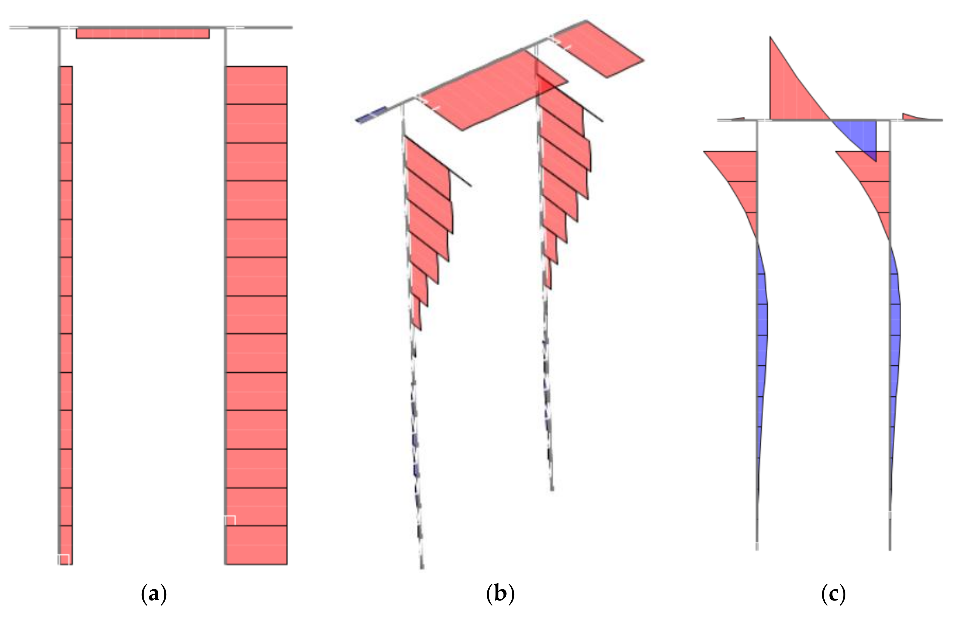
Indicative axial force, shear force and bending moment diagrams of one set of piles are illustrated in Figure 17. It is observed that the outward pile develops a smaller compressive axial force, while the placement of the auxiliary corner tube directly above the inward pile, thus directly transmitting to it its vertical reaction component, cancels the inward pile’s tension due to the horizontal reaction component, leading to a larger overall compression. This can be further optimized by the appropriate placement of the corner tube on the pile cap.
It is further observed that, for the considered soil properties, the developing shear forces and bending moments diminish smoothly towards the pile bottom, thus indicating a sufficient pile embedment depth. The maximum calculated shear force is approximately equal to 1400 kN, leading to required shear reinforcement of 40 cm2/m that can be covered by Ø16/10 spiral links, while the worst combination of axial force and bending moment consists of 3750 kN and 3100 kNm, respectively, leading to a required longitudinal reinforcement of 240 cm2 (3%), which can be covered by 34 Ø30. These are considered as reasonable reinforcement demands, confirming the adequacy of the considered pile cross-section.
As a first approach towards evaluating the effect of the tripod’s stiffness to the overall stiffness of the tower assembly, which is important for resonance verification, it has first been attempted to replace the tripod by an equivalent rotational spring at the base of the tubular upper part. To that effect, a concentrated bending moment equal to 100,000 kNm has been applied at the tripod top, and the corresponding rotation has been calculated. This has been repeated in all three directions identified in Figure 12, leading to very similar rotations in all cases, equal to 0.0065 rad. The corresponding rotational spring stiffness is then computed equal to approximately 15,300 MNm/rad. Referring to Reference [10], where the influence of a base rotational spring on the fundamental vibration frequency of a tubular wind turbine tower was investigated, it is estimated that the tripod and its foundation will cause a reduction in the order of 15% to the fundamental vibration frequency that the tubular superstructure would have if it were fixed at its base.
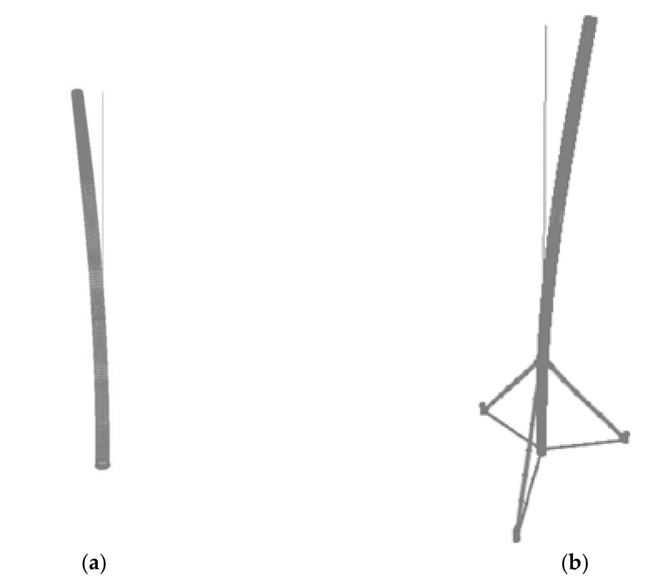
In order to isolate the effect of the foundation, the same process has been repeated for the case of a rigidly fixed tripod, leading to a rotation of 0.0064 rad at the top of the tripod, as well as a rigidly hinged tripod, leading to a rotation of 0.0066 rad, thus identifying a negligible influence of the foundation stiffness for the considered soil type. Subsequently, a typical 120-m-tall tubular superstructure, comprising a fundamental frequency ω1 = 1.10 rad/s if fixed at its base, was modeled on top of the tripod. Assuming a rigidly hinged tripod, the reduced frequency of the overall assembly was found to be equal to 0.92 rad/s, corresponding to a 16% reduction, not far from the rotational spring approximation. Having a specific hub height target for the wind turbine, desirable frequency values can thus be achieved by appropriately adjusting the tripod height and radius, which are the two main parameters controlling the tripod stiffness. The fundamental vibration modes and the corresponding frequencies of the 120-m-tall tubular and the same on top of the tripod are illustrated in Figure 18.
3.5. Weight and Cost Considerations
For the dimensions and cross-sections described above, the estimated weight of the tripod parts consists of 210 t for the three upper legs, 35 t for the three lower legs, 200 t for the vertical leg and 35 t for the three corner tubes, adding up to 480 t, which includes approximate weights of the necessary ring flanges. Considering an approximate weight of 320 t for the conventional tubular upper part, a safe estimate of the total steel weight for the 180-m tower assembly would be around 800 t. It is noted that the smaller diameter tubes of the upper, lower and corner legs could be fabricated by other methods than cold curving, such as spiral welding, resulting in significant savings in unit price.
Regarding the foundation, assuming a relatively stiff soil, a total of six piles of 1 m diameter and an embedment length in the order of 20 m and an estimated concrete volume of 160 m3 for the pile caps would lead to a foundation cost approximately at 50% of the mat foundation of a conventional tubular tower.
The combined superstructure and foundation cost for a tower with an 180-m hub height is expected to be in the range of 15–40% less than the corresponding tubular steel, concrete and hybrid solutions, notwithstanding the fact that this height would be unrealistic for a conventional tubular steel tower with ring flange connections. These findings justify considerable optimism that the proposed concept may offer a competitive solution for achieving taller hub heights for onshore wind turbines of high-rated power.
4. Discussion
The tripod substructure investigated in this paper has been proposed as one, among several, alternative concepts that are investigated in an effort to enable wind turbine towers to reach very tall hub heights in order to better exploit the available wind potential. The underlying motivation is to transfer the advantages of the tripod as a structural system, already applied in some offshore wind turbine tower designs, to onshore towers, where transportation by trucks instead of vessels imposes stricter constraints upon the size of transportable parts. Moreover, the size of the structure and imposed loads cause very large developing action effects to be resisted by the structural members and their connections, leading to the need for novel and effective constructional details.
In the first part of this paper, a qualitative presentation of the proposed structural concept, including joint alternatives and a foundation arrangement, was presented. Successive steps of an erection methodology were also described to support the technological feasibility.
In the second part of the paper, a preliminary structural investigation of a typical case study was presented, comprising a 180-m-tall tower, consisting of a 120-m-tall tubular superstructure on top of a 60-m-tall tripod substructure. Indicative sections were calculated demonstrating that conventional tubular sections may be employed for the vertical tripod leg, while commercially available, smaller diameter, tubular sections may be utilized for the inclined legs for a reduced cost. In terms of weight and cost, the proposed solution seems to be competitive compared to other tower types for large hub heights.
Further work is necessary in order to bring this concept closer to realization. Advancing the current preliminary design requires local buckling verification of the tubular legs and detailed designs of the connections, including fatigue verification, to define the local shell thickness at the joints, location and thickness of the eventual stiffeners, thickness of the ring flanges and number and type of bolts. Analytical and numerical calculations must be verified by comparison to the experimental results obtained from small-scale models at the tripod level, as well as large-scale models at the joint level. Parametric studies investigating the effects of the tripod geometry, soil type and imposed loads will then provide additional insights to assist the optimized design of such structures.
5. Conclusions
A tripod substructure was proposed as a realistic, modular and scalable solution for wind turbine towers of very large heights. Thanks to its scalability, the concept can also be used for repowering existing wind farms without replacing the towers and turbines but by simply elevating them to exploit the improved wind conditions at taller heights and, thus, to increase power production. Compared to fully pre-welded tripod assemblies that have been used in offshore applications, in the proposed concept, the tripod consists of pre-welded individual tripod parts that can be transported by trucks and are then bolted together during erection, thus satisfying the transportability constraints for onshore applications.
Compared to other modular tripod solutions that can be found in the literature but have not been used in real, large-scale applications, in the proposed concept tubular sections are used for all the tripod legs, featuring sufficient buckling, bending and torsional resistance to withstand the developing action effects for large overall tower heights. The difficulty resulting from bolting together on-site individual members comprising tubular sections is addressed in this paper by proposing novel constructional details that can satisfy all the necessary verification criteria related to safety and operation while, at the same time, respecting the fabrication, onshore and offshore transportation, erection, maintenance and dismantling constraints.
Contrary to the existing tubular towers that have, in most cases, a heavy reinforced concrete mat foundation in order to counterbalance the large imposed bending moments, the tripod support structure utilizes a lighter and more cost-effective foundation solution based on reinforced concrete piles below each tripod leg. This foundation type enables the easy adjustment to uneven terrains and to local soil conditions.
A preliminary structural investigation indicated the feasibility of the concept and provided indicative section requirements. A rough cost estimation based on these sections illustrated the competitiveness of the proposed solution compared to other tower types for large hub heights.
6. Patents
A patent application has been submitted and is under evaluation describing the work reported in this manuscript [94].
Author Contributions
C.J.G. proposed the concept and joint details, developed the methodology, supervised the project and was mainly responsible for writing and editing of this manuscript. M.V.B. prepared the three-dimensional drawings, developed the numerical analysis model, carried out structural analysis and design and contributed to writing Section 3.4. M.G. was responsible for the issues pertaining to the fabrication and maintenance, provided loading information and contributed to writing the pertinent parts of Section 2.1. S.G. was responsible for the issues related to transportation and erection, carried out the weight and cost estimations and contributed to writing Section 2.4 and Section 3.5. All authors have read and agreed to the published version of the manuscript.
Funding
This research received no external funding.
Conflicts of Interest
The authors declare no conflict of interest.
References
- 2030 Climate & Energy Framework. Available online: https://ec.europa.eu/clima/policies/strategies/2030_en#tab-0-0 (accessed on 18 July 2021).
- International Energy Agency. Net Zero by 2050—A Roadmap for the Global Energy Sector, 2nd Revision. June 2021. Available online: https://www.iea.org/reports/net-zero-by-2050 (accessed on 18 July 2021).
- Global Wind Energy Council. Global Wind Report 2021. Available online: https://gwec.net/global-wind-report-2021/ (accessed on 18 July 2021).
- Burton, T.; Jenkins, N.; Sharpe, D.; Bossanyi, E. Wind Energy Handbook, 2nd ed.; John Wiley & Sons, Ltd.: Oxford, UK, 2011. [Google Scholar]
- Hau, E. Wind Turbines: Fundamentals, Technologies, Application, Economics, 3rd ed.; Springer: Berlin/Heidelberg, Germany, 2013. [Google Scholar]
- Stiebler, M. Wind Energy Systems for Electric Power Generation; Springer: Berlin/Heidelberg, Germany, 2008. [Google Scholar]
- Hansen, M. Aerodynamics of Wind Turbines, 2nd ed.; Earthscan: London, UK, 2008. [Google Scholar]
- Baniotopoulos, C.; Borri, C.; Stathopoulos, T. Environmental Wind Engineering and Design of Wind Energy Structures; Springer: Wien, Austria; New York, NY, USA, 2011. [Google Scholar]
- Veljkovic, M.; Feldmann, M.; Naumes, J.; Pak, D.; Simões, L.; da Silva; Rebelo, C. Wind turbine tower design, erection and maintenance. In Wind Energy Systems: Optimising Design and Construction for Safe and Reliable Operation; Sørensen, J.D., Sørensen, J.N., Eds.; Woodhead Publishing Series in Energy: Cambridge, UK, 2011; pp. 274–300. [Google Scholar] [CrossRef]
- Koulatsou, K.G.; Kazakis, G.; Gantes, C.J.; Lagaros, N.D. Resonance investigation and its effects on weight optimization of tubular steel wind turbine towers. Procedia Manuf. 2020, 44, 4–11. [Google Scholar] [CrossRef]
- Bazeos, N.; Hatzigeorgiou, G.D.; Hondros, I.D.; Karamaneas, H.; Karabalis, D.L.; Beskos, D.E. Static, seismic and stability analyses of a prototype wind turbine steel tower. Eng. Struct. 2002, 24, 1015–1025. [Google Scholar] [CrossRef]
- Lavassas, I.; Nikolaidis, G.; Zervas, P.; Efthimiou, E.; Doudoumis, I.N.; Baniotopoulos, C.C. Analysis and design of the prototype of a steel 1-MW wind turbine tower. Eng. Struct. 2003, 25, 1097–1106. [Google Scholar] [CrossRef]
- Rebelo, C.; Moura, A.; Gervásio, H.; Veljkovic, M.; Simões da Silva, L. Comparative life cycle assessment of tubular wind towers and foundations—Part 1: Structural design. Eng. Struct. 2014, 74, 283–291. [Google Scholar] [CrossRef]
- Zhao, Z.; Dai, K.; Camara, A.; Bitsuamlak, G.; Sheng, C. Wind turbine tower failure modes under seismic and wind loads. J. Perform. Constr. Facil. 2019, 33, 04019015. [Google Scholar] [CrossRef]
- Pons, O.; de la Fuente, A.; Armengou, J.; Aguado, A. Towards the sustainability in the design of wind towers. Energy Procedia 2017, 115, 41–49. [Google Scholar] [CrossRef] [Green Version]
- Hernandez-Estrada, E.; Lastres-Danguillecourt, O.; Robles-Ocampo, J.B.; Lopez-Lopez, A.; Sevilla-Camacho, P.Y.; Perez-Sariñana, B.Y.; Dorrego-Portela, J.R. Considerations for the structural snalysis and design of wind turbine towers: A review. Renew. Sust. Energ. Rev. 2021, 137, 110447. [Google Scholar] [CrossRef]
- Ma, Y.; Martinez-Vazquez, P.; Baniotopoulos, C. Buckling analysis for wind turbine tower design: Thrust load versus compression load based on energy method. Energies 2020, 13, 5302. [Google Scholar] [CrossRef]
- Gerasimidis, S.; Hutchinson, J.W. Dent imperfections in shell buckling: The role of geometry, residual stress, and plasticity. J. Appl. Mech. 2021, 88, 031007. [Google Scholar] [CrossRef]
- Yadav, K.K.; Cuccia, N.L.; Virot, E.; Rubinstein, S.M.; Gerasimidis, S. A nondestructive technique for the evaluation of thin cylindrical shells’ axial buckling capacity. J. Appl. Mech. 2021, 88, 051003. [Google Scholar] [CrossRef]
- Mikitarenko, M.A.; Perelmuter, A.V. Safe fatigue life of steel towers under the action of wind vibrations. J. Wind Eng. Ind. Aerodyn. 1998, 74–76, 1091–1100. [Google Scholar] [CrossRef]
- Berny-Brandt, E.A.; Ruiz, S.E. Reliability over time of wind turbines steel towers subjected to fatigue. Wind. Struct. An Int. J. 2016, 23, 75–90. [Google Scholar] [CrossRef]
- Huo, T.; Tong, L. An approach to wind-induced fatigue analysis of wind turbine tubular towers. J. Construct. Steel Res. 2020, 166, 105917. [Google Scholar] [CrossRef]
- Bernuzzi, C.; Crespi, P.; Montuori, R.; Nastri, E.; Simoncelli, M.; Stochino, F.; Zucca, M. Resonance of steel wind turbines: Problems and solutions. Structures 2021, 32, 65–75. [Google Scholar] [CrossRef]
- European Committee of Standardization. EN1993-1-6:2007, Eurocode 3: Design of Steel Structures—Part 1.6: Strength and Stability of Shell Structures; European Committee of Standardization: Brussels, Belgium, 2007. [Google Scholar]
- European Committee of Standardization. EN1993-1-6:2007/A1:2015, Eurocode 3: Design of Steel Structures—Part 1.6: Strength and Stability of Shell Structures—Corrigendum; European Committee of Standardization: Brussels, Belgium, 2015. [Google Scholar]
- European Committee of Standardization. EN1993-1-9:2005, Eurocode 3: Design of Steel Structures—Part 1.9: Fatigue; European Committee of Standardization: Brussels, Belgium, 2005. [Google Scholar]
- International Electrotechnical Commission. IEC61400-1:2005, Wind Turbines—Part 1: Design Requirements, International Standard, 3rd ed.; International Electrotechnical Commission: Geneva, Switzerland, 2005. [Google Scholar]
- Germanischer Lloyd. Guideline for the Certification of Wind Turbines; Germanischer Lloyd: Hamburg, Germany, 2010. [Google Scholar]
- Det Norske Veritas (DNV). Wind Energy Department, Risø National Laboratory. Guidelines for Design of Wind Turbines. Available online: https://www.kimerius.com/app/download/5784679452/Guidelines+for+design+of+wind+turbines.pdf (accessed on 9 September 2021).
- DNV GL.; DNVGL-ST-0126. Support Structures for Wind Turbines. Available online: https://rules.dnv.com/docs/pdf/DNV/ST/2016-04/DNVGL-ST-0126.pdf (accessed on 9 September 2021).
- Hu, Y.; Baniotopoulos, C.; Yang, J. Effect of internal stiffening rings and wall thickness on the structural response of steel wind turbine towers. Eng. Struct. 2014, 81, 148–161. [Google Scholar] [CrossRef]
- Stavridou, N.; Efthymiou, E.; Gerasimidis, S.; Baniotopoulos, C.C. Investigation of stiffening scheme effectiveness towards buckling stability enhancement in tubular steel wind turbine towers. Steel Compos. Struct. 2015, 19, 1115–1144. [Google Scholar] [CrossRef]
- Hu, Y.; Yang, J.; Baniotopoulos, C. Study of the bearing capacity of stiffened tall offshore wind turbine towers during the erection phase. Energies 2020, 13, 5102. [Google Scholar] [CrossRef]
- Dimopoulos, C.A.; Gantes, C.J. Experimental investigation of buckling of wind turbine tower cylindrical shells with opening and stiffening under bending. Thin Walled Struct. 2012, 54, 140–155. [Google Scholar] [CrossRef]
- Dimopoulos, C.A.; Gantes, C.J. Comparison of stiffening types of the cutout in tubular wind turbine towers. J. Construct. Steel Res. 2013, 83, 62–74. [Google Scholar] [CrossRef]
- Tran, A.; Veljkovic, M.; Rebelo, C.; Simões da Silva, L. Resistance of door openings in towers for wind turbines. In Proceedings of the SEECCM III—3rd South-East European Conference on Computational Mechanics—An ECCOMAS and IACM Special Interest Conference, Kos Island, Greece, 12–14 June 2013; Papadrakakis, M., Kojic, M., Tuncer, I., Papadopoulos, V., Eds.; SEECCM 2013: Kos Island, Greece, 2013. [Google Scholar] [CrossRef] [Green Version]
- Dimopoulos, C.A.; Koulatsou, K.; Petrini, F.; Gantes, C.J. Assessment of stiffening type of the cutout in tubular wind turbine towers under artificial dynamic wind actions. J. Comput. Nonlinear Dyn. 2015, 10, 041004. [Google Scholar] [CrossRef]
- Alsalah, A.; Holloway, D.; Ghanbari Ghazijahani, T. Recovery of capacity lost due to openings in cylindrical shells under compression. J. Construct. Steel Res. 2017, 137, 169–179. [Google Scholar] [CrossRef]
- Pedersen, N.L. On analysis and redesign of bolted L-flanged connections. Wind Energy 2017, 20, 1069–1082. [Google Scholar] [CrossRef] [Green Version]
- Tobinaga, I.; Ishihara, T. A study of action point correction factor for L-type flanges of wind turbine towers. Wind Energy 2018, 21, 801–806. [Google Scholar] [CrossRef]
- Giaccu, G.F.; Caracoglia, L. Wind-load fragility analysis of monopole towers by layered stochastic-approximation-Monte-Carlo method. Eng. Struct. 2018, 174, 462–477. [Google Scholar] [CrossRef]
- Santos, R.R.; Cho, S.-J.; Park, J.-S. Ultimate strength of 10 MW wind turbine tower considering opening, stiffener, and initial imperfection. Int. J. Steel Struct. 2018, 18, 1318–1324. [Google Scholar] [CrossRef]
- Sadowski, A.J. On the advantages of hybrid beam-shell structural finite element models for the efficient analysis of metal wind turbine support towers. Finite Elem. Anal. Des. 2019, 162, 19–33. [Google Scholar] [CrossRef]
- Yeter, B.; Garbatov, Y.; Guedes Soares, C. Numerical and experimental study of the ultimate strength of a monopile structure. Eng. Struct. 2019, 194, 290–299. [Google Scholar] [CrossRef]
- Chou, J.-S.; Ou, Y.-C.; Lin, K.-Y. Collapse mechanism and risk management of wind turbine tower in strong wind. J. Wind Eng. Ind. Aerodyn. 2019, 193, 103962. [Google Scholar] [CrossRef]
- Inzunza-Aragón, I.; Ruiz, S.E. Capacity and demand factors changing over time. Application to wind turbine steel towers. Eng. Struct. 2020, 206, 110156. [Google Scholar] [CrossRef]
- Campione, G. Simple equations for strength and deformability verification of tubular steel wind turbine towers. Eng. Struct. 2021, 228, 111566. [Google Scholar] [CrossRef]
- Negm, H.M.; Maalawi, K.Y. Structural design optimization of wind turbine towers. Comput. Struct. 2000, 74, 649–666. [Google Scholar] [CrossRef]
- Uys, P.E.; Farkas, J.; Jármai, K.; van Tonder, F. Optimization of a steel tower for a wind turbine structure. Eng. Struct. 2007, 29, 1337–1342. [Google Scholar] [CrossRef]
- Lagaros, N.D.; Karlaftis, M.G. Life-cycle cost structural design optimization of steel wind towers. Comput. Struct. 2016, 174, 122–132. [Google Scholar] [CrossRef]
- Al-Sanad, S.; Wang, L.; Parol, J.; Kolios, A. Reliability-based design optimisation framework for wind turbine towers. Renew. Energ. 2021, 167, 942–953. [Google Scholar] [CrossRef]
- Adhikari, R.C.; Wood, D.H.; Sudak, L. Design procedure for tubular lattice towers for small wind turbines. Wind Eng. 2014, 38, 359–376. [Google Scholar] [CrossRef]
- Jovašević, S.; Mohammadi, M.R.S.; Rebelo, C.; Pavlović, M.; Veljković, M. New lattice-tubular tower for onshore WEC—Part 1: Structural optimization. Procedia Eng. 2017, 199, 3236–3241. [Google Scholar] [CrossRef]
- Stavridou, N.; Koltsakis, E.; Baniotopoulos, C. Structural analysis and optimal design of steel lattice wind turbine towers. Struct. Build. 2019, 172, 564–579. [Google Scholar] [CrossRef]
- Jovasevic, S.; Correia, J.; Pavlovic, M.; Dantas, R.; Rebelo, C.; Veljkovic, M.; de Jesus, A.M.P. Alternative steel lattice structures for wind energy converters. Int. J. Struct. Integr. 2021, 12, 48–69. [Google Scholar] [CrossRef]
- Stavridou, N.; Koltsakis, E.; Baniotopoulos, C. Lattice and tubular steel wind turbine towers. Comparative structural investigation. Energies 2020, 13, 6325. [Google Scholar] [CrossRef]
- Veljkovic, M.; Feldmann, M.; Naumes, J.; Pak, D.; Rebelo, C.; Simões da Silva, L. Friction connection in tubular towers for a wind turbine. Stahlbau 2010, 79, 660–668. [Google Scholar] [CrossRef]
- Pavlović, M.; Heistermann, C.; Veljković, M.; Pak, D.; Feldmann, M.; Rebelo, C.; Simões da Silva, L. Friction connection vs. ring flange connection in steel towers for wind converters. Eng. Struct. 2015, 98, 151–162. [Google Scholar] [CrossRef]
- Pavlović, M.; Heistermann, C.; Veljković, M.; Pak, D.; Feldmann, M.; Rebelo, C.; Simões da Silva, L. Connections in towers for wind converters, Part I: Evaluation of down-scaled experiments. J. Construct. Steel Res. 2015, 115, 445–457. [Google Scholar] [CrossRef]
- Pavlović, M.; Heistermann, C.; Veljković, M.; Pak, D.; Feldmann, M.; Rebelo, C.; Simões da Silva, L. Connections in towers for wind converters, Part II: The friction connection behaviour. J. Construct. Steel Res. 2015, 115, 458–466. [Google Scholar] [CrossRef]
- Heistermann, C.; Pavlović, M.; Veljković, M.; Pak, D.; Feldmann, M.; Rebelo, C.; Simões da Silva, L. Influence of execution tolerances for friction connections in circular and polygonal towers for wind converters. Adv. Steel Constr. 2017, 13, 343–360. [Google Scholar] [CrossRef]
- Lagerwey Tower Solutions. Available online: https://www.lagerwey.com/technology/tower/ (accessed on 18 July 2021).
- News Release from Vestas Wind Systems A/S: New Tower Enables Increased Power Production at Low Wind Sites. Available online: https://www.vestas.com/en/media/~/media/92670482644d4e5bb751ff6bd6f66a43.ashx (accessed on 18 July 2021).
- Campione, G.; Cannella, F.; Zizzo, M.; Pauletta, M. Buckling strength of steel tube for lifting telescopic wind steel tower. Eng. Fail. Anal. 2021, 121, 105153. [Google Scholar] [CrossRef]
- Pantano, A.; Tucciarelli, T.; Montinaro, N.; Mancino, A. Design of a telescopic tower for wind energy production with reduced environmental impact. Int. J. Precis. Eng. Manuf. 2020, 7, 119–130. [Google Scholar] [CrossRef]
- Yadav, K.K.; Gerasimidis, S. Imperfection insensitivity of thin wavy cylindrical shells under axial compression or bending. J. Appl. Mech. 2020, 87, 041003. [Google Scholar] [CrossRef]
- Yadav, K.K.; Gerasimidis, S. Imperfection insensitive thin cylindrical shells for next generation wind turbine towers. J. Construct. Steel Res. 2020, 172, 106228. [Google Scholar] [CrossRef]
- Ibrahim, A.; Diso, I.S.; Auwal, S.T.; Ibrahim, M.A.; Dambatta, M.S.; Ramesh, S. Design of self-erecting tower for a wind turbine. Int. J. Eng. Res. Technol. 2020, 6, 63–82. [Google Scholar] [CrossRef]
- Jay, A.; Myers, A.T.; Torabian, S.; Mahmoud, A.; Smith, E.; Agbayani, N.; Schafer, B.W. Spirally welded steel wind towers: Buckling experiments, analyses, and research needs. J. Construct. Steel Res. 2016, 125, 218–226. [Google Scholar] [CrossRef] [Green Version]
- Keystone Tower Systems: On-Site Fabrication. Available online: https://keystonetowersystems.com/onsite (accessed on 18 July 2021).
- Mohammadi, M.R.S.; Richter, C.; Pak, D.; Rebelo, C.; Feldmann, M. Steel hybrid onshore wind towers installed with minimal effort: Development of lifting process. Wind Eng. 2018, 42, 335–352. [Google Scholar] [CrossRef]
- Gkantou, M.; Rebelo, C.; Baniotopoulos, C. Life cycle assessment of tall onshore hybrid steel wind turbine towers. Energies 2020, 13, 3950. [Google Scholar] [CrossRef]
- Jin, Q.; Li, V.C. Structural and durability assessment of ECC/concrete dual-layer system for tall wind turbine towers. Eng. Struct. 2019, 196, 109338. [Google Scholar] [CrossRef]
- Alves de Lana, J.; Américo Almeida Magalhães Júnior, P.; Almeida Magalhães, C.; Mendonça Almeida Magalhães, A.L.; Carlos de Andrade Junior, A.; Silveira de Barros Ribeiro, M. Behavior study of prestressed concrete wind-turbine tower in circular cross-section. Eng. Struct. 2021, 227, 111403. [Google Scholar] [CrossRef]
- Schaumann, P.; Keindorf, C. Sandwich-towers for wind energy converters. Dewi Mag. 2008, 33, 65–76. [Google Scholar]
- Li, W.; Wang, D.; Han, L.-H. Behaviour of grout-filled double skin steel tubes under compression and bending: Experiments. Thin Walled Struct. 2017, 116, 307–319. [Google Scholar] [CrossRef]
- Tziavos, N.I.; Gkantou, M.; Theofanous, M.; Dirar, S.; Baniotopoulos, C. Behaviour of grout-filled double-skin tubular steel stub-columns: Numerical modelling and design considerations. Structures 2020, 27, 1623–1636. [Google Scholar] [CrossRef]
- Vernardos, S.M.; Gantes, C.J.; Badogiannis, E.G.; Lignos, X.A. Experimental and numerical investigation of steel-grout-steel sandwich shells for wind turbine towers. J. Construct. Steel Res. 2021, 184, 106815. [Google Scholar] [CrossRef]
- Petrini, F.; Manenti, S.; Gkoumas, K.; Bontempi, F. Structural design and analysis of offshore wind turbines from a system point of view. Wind Eng. 2010, 34, 85–108. [Google Scholar] [CrossRef] [Green Version]
- Wang, X.; Zeng, X.; Li, J.; Yang, X.; Wang, H. A review on recent advancements of substructures for offshore wind turbines. Energy Convers. Manag. 2018, 158, 103–119. [Google Scholar] [CrossRef]
- Hu, Y.; Yang, J.; Baniotopoulos, C.; Wang, X.; Deng, X. Dynamic analysis of offshore steel wind turbine towers subjected to wind, wave and current loading during construction. Ocean Eng. 2020, 216, 108084. [Google Scholar] [CrossRef]
- Jiang, Z. Installation of offshore wind turbines: A technical review. Renew. Sust. Energ. Rev. 2021, 139, 110576. [Google Scholar] [CrossRef]
- Yeter, B.; Garbatov, Y.; Guedes Soares, C. Fatigue damage assessment of fixed offshore wind turbine tripod support structures. Eng. Struct. 2015, 101, 518–528. [Google Scholar] [CrossRef]
- Hao, E.T.; Liu, C.G. Evaluation and comparison of anti-impact performance to offshore wind turbine foundations: Monopile, tripod, and jacket. Ocean Eng. 2017, 130, 218–227. [Google Scholar] [CrossRef]
- Ma, H.; Yang, J.; Chen, L. Effect of scour on the structural response of an offshore wind turbine supported on tripod foundation. Appl. Ocean Res. 2018, 73, 179–189. [Google Scholar] [CrossRef]
- Arcigni, F.; Abhinav, K.A.; Collu, M.; Venturini, M. Analysis of tripod supported offshore wind turbines under conditions of marine growth. Ocean Eng. 2021, 220, 108441. [Google Scholar] [CrossRef]
- Alpha Ventus Offshore Wind Farm. Available online: https://en.wikipedia.org/wiki/Alpha_Ventus_Offshore_Wind_Farm (accessed on 24 August 2021).
- Trianel Windpark Borkum. Available online: https://en.wikipedia.org/wiki/Trianel_Windpark_Borkum (accessed on 24 August 2021).
- Tripod (foundation). Available online: https://en.wikipedia.org/wiki/Tripod_(foundation) (accessed on 24 August 2021).
- Multibrid M5000. Available online: https://en.wind-turbine-models.com/turbines/22-multibrid-m5000 (accessed on 18 July 2021).
- General Electric Company. Wind Turbine Tower Assembly and Method for Assembling the Same. United. States Patent No. US 8,544.214 B2, 1 October 2013.
- General Electric Company. Onshore Wind Turbine with Tower Support System. European Patent Application No. EP 2 444 663 A3, 14 December 2016.
- Siemens Aktiengesellschaft. A Support Structure for a Wind Turbine. International Patent Application No. WO 2011/147477 A1, 1 December 2011.
- ATES CELIK INS. TAAH. PROJE MUH. SAN. VE TIC. A.S. A Multi-Pod Support Structure for a Wind Turbine Tower. PCT Application No. PCT/TR2020/051117; unpublished,
Figure 1.
Main parts of proposed wind turbine tower assembly.

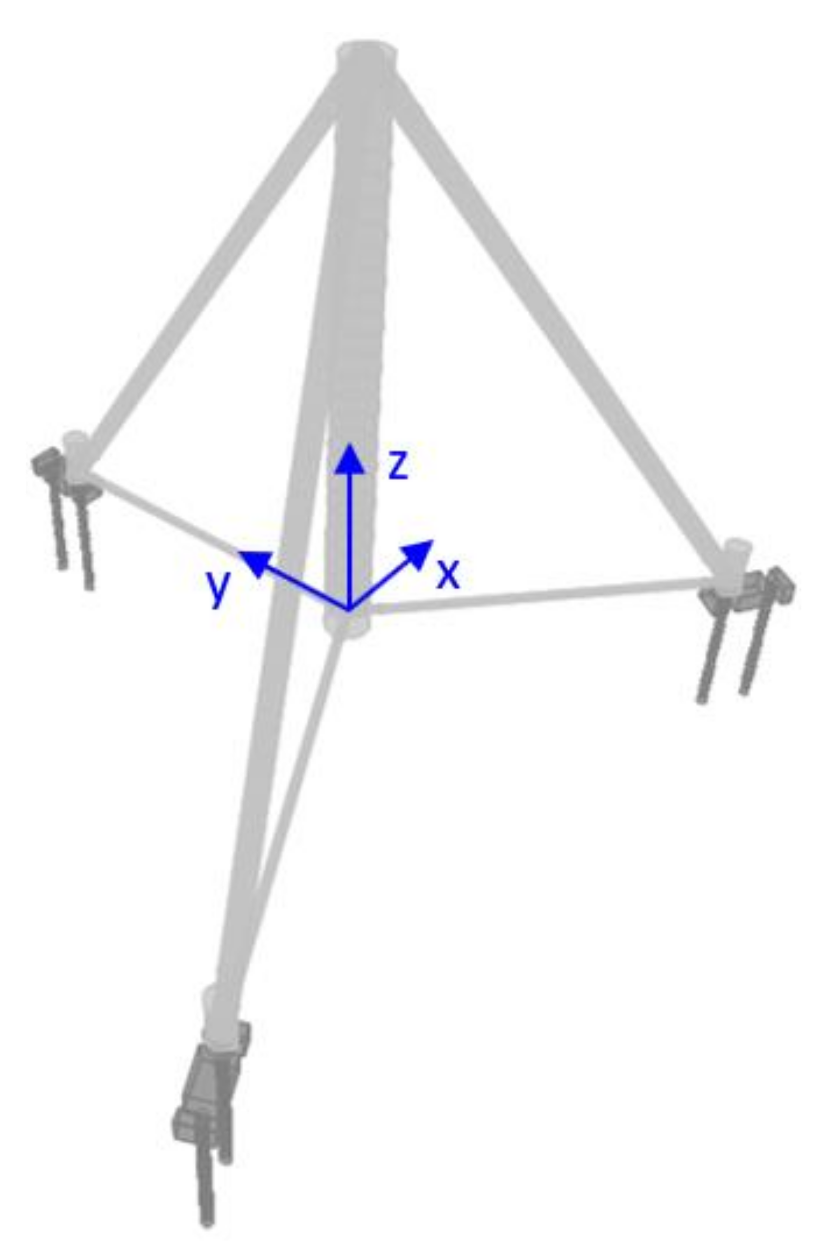
Figure 2.
Main parts of tripod support structure.

Figure 3.
Segmental upper junction piece: (a) upper section of upper inclined leg with welded segmental upper junction piece and (b) details of a segmental upper junction piece.
Figure 3.
Segmental upper junction piece: (a) upper section of upper inclined leg with welded segmental upper junction piece and (b) details of a segmental upper junction piece.

Figure 4.
Details of a unified upper junction piece.

Figure 5.
Details of a unified lower junction piece: (a) view from the top and (b) view from the bottom.
Figure 5.
Details of a unified lower junction piece: (a) view from the top and (b) view from the bottom.

Figure 6.
Corner junction: (a) corner junction piece supported on a pile cap and piles and (b) details of a unified corner junction piece.
Figure 6.
Corner junction: (a) corner junction piece supported on a pile cap and piles and (b) details of a unified corner junction piece.

Figure 7.
Details of a segmental corner junction piece (a) inner part; (b) outer part.

Figure 8.
Foundation tie rods: (a) triangular arrangement and (b) radial arrangement.

Figure 9.
Successive steps of the erection methodology (a) construction of foundation; (b) anchoring of corner junction pieces; (c) placement of temporary support structure and connection of lower inclined legs; (d) connection of successive parts of vertical leg; (e) connection of upper inclined legs and removal of temporary support structure; (f) connection of successive parts of tubular superstructure.

Figure 10.
Case study geometry.

Figure 11.
p–y curves representing soil–pile interactions.

Figure 12.
Loading scenarios illustrated on the tripod’s plane view: (a) loading scenario 1, (b) loading scenario 2 and (c) loading scenario 3.
Figure 12.
Loading scenarios illustrated on the tripod’s plane view: (a) loading scenario 1, (b) loading scenario 2 and (c) loading scenario 3.

Figure 13.
Numerical model.

Figure 14.
Deformed shapes (exaggerated deformation scale): (a) loading scenario 1, (b) loading scenario 2, and (c) loading scenario 3.
Figure 14.
Deformed shapes (exaggerated deformation scale): (a) loading scenario 1, (b) loading scenario 2, and (c) loading scenario 3.

Figure 15.
Axial force and bending moment diagrams for loading scenario 1: (a) axial forces, (b) bending moments M2 and (c) bending moments M3.
Figure 15.
Axial force and bending moment diagrams for loading scenario 1: (a) axial forces, (b) bending moments M2 and (c) bending moments M3.

Figure 16.
Utilization ratios of the steel superstructure considering all the loading scenarios.

Figure 17.
Axial force, shear force and bending moment diagrams of one set of piles: (a) axial forces, (b) shear forces and (c) bending moments.
Figure 17.
Axial force, shear force and bending moment diagrams of one set of piles: (a) axial forces, (b) shear forces and (c) bending moments.

Figure 18.
Fundamental vibration modes and corresponding frequencies: (a) a typical 120-m-tall tubular tower (ω1 = 1.10 rad/s) and (b) the overall 180-m-tall tower assembly (ω1 = 0.92 rad/s).
Figure 18.
Fundamental vibration modes and corresponding frequencies: (a) a typical 120-m-tall tubular tower (ω1 = 1.10 rad/s) and (b) the overall 180-m-tall tower assembly (ω1 = 0.92 rad/s).

Publisher’s Note: MDPI stays neutral with regard to jurisdictional claims in published maps and institutional affiliations. |
© 2021 by the authors. Licensee MDPI, Basel, Switzerland. This article is an open access article distributed under the terms and conditions of the Creative Commons Attribution (CC BY) license (https://creativecommons.org/licenses/by/4.0/).
Share and Cite
MDPI and ACS Style
Gantes, C.J.; Villi Billi, M.; Güldogan, M.; Gül, S. A Novel Tripod Concept for Onshore Wind Turbine Towers. Energies 2021, 14, 5772. https://doi.org/10.3390/en14185772
AMA Style
Gantes CJ, Villi Billi M, Güldogan M, Gül S. A Novel Tripod Concept for Onshore Wind Turbine Towers. Energies. 2021; 14(18):5772. https://doi.org/10.3390/en14185772
Chicago/Turabian StyleGantes, Charis J., Maria Villi Billi, Mahmut Güldogan, and Semih Gül. 2021. "A Novel Tripod Concept for Onshore Wind Turbine Towers" Energies 14, no. 18: 5772. https://doi.org/10.3390/en14185772
Note that from the first issue of 2016, this journal uses article numbers instead of page numbers. See further details here.