1. Introduction
Radial flux machines with magnets inserted in a rotor core motor come in various configurations and are widely used for electric and hybrid traction applications [
1,
2,
3,
4]. With their high efficiency and power density, IPM synchronous machines have been employed in many commercialized electrified vehicles [
5,
6].
In an embedded PM motor design with the magnetic flux barriers, properties of electrical devices vary, depending on the path of magnetic flux produced by the magnet. By changing the magnetic flux path in the desired direction, it is possible to improve the power and the efficiency, as well as to reduce the cogging torque and the torque ripple [
7,
8]. PMs inserted within the rotor core can be formed in various configurations [
3,
9,
10,
11,
12], resulting in a nonuniform magnetic distribution on the rotor surface [
13]. This situation involves significant disadvantages such as an increase in the cogging torque harmonics and a torque ripple coefficient level. In consequence, the electric motor generates higher vibrations and noise, and this may lead to damage in the whole drive system. As the cogging torque significantly influences the occurrence of noise and vibrations in the motor, it is necessary to reduce it as much as possible at the design stage [
14,
15,
16,
17]. In the literature, one can also find works describing various methods of optimizing the operating parameters of IPMSM machines, effectively increasing their efficiency [
18,
19,
20]. Furthermore, manufacturers are interested in investigating not only winding short-circuit faults leading to a considerable rise in the transient current [
21,
22,
23,
24,
25], but also the transient electromagnetic torque waveform which can be characterized by very high amplitudes/peaks. This study intends to determine the best approaches to making the motors more salable and reliable.
In this paper, the authors attempted to analyze two similar motors differing in the number of slots per rotor pole and in the stator winding. The first motor used distributed winding (DW) and the second motor used concentrated winding (CW) [
26,
27,
28,
29,
30]. Because the electromagnetic torque of the IPM motor is developed due to an interaction between the stator winding field and the rotor PM field in the air gap, the transient electromagnetic torque during stator faulty operation should provide interesting results, pointing toward a more stable motor. In both cases, it is important to design PMs of ideal shape with an appropriate distance between them. Otherwise, any distortions of the magnetic flux density distribution in the airgap can result in a considerable increase in the torque ripples and in the amplitude of the slot harmonics. These harmonics are highly sensitive to the degree of fault. Another extremely important reason for the poorer performance of an electrical motor is the tolerance of PM mounting in the rotor core [
31,
32,
33,
34].
Today, manufacturers of electric vehicles are increasingly aware of the failure of electric motors in relation to short-circuit conditions of the stator windings. They want to understand the transient behavior of PMSM machines when a short-circuit occurs. An important study that has not yet been extensively developed, taken into account at the first stage of machine design, is an analysis of the external load collapses at the impedance of 0 Ω for all phases. An analysis of the function of current and torque over time, showing the machine operating as a generator, the load collapsing, and then the transient response of the system until it stabilizes, is very important to assess the risk of machine failure.
Another effect of relatively high amplitudes of phase currents in transient states, rarely discussed in the literature, is a possible accelerated degradation of permanent magnets. In this study, in addition to the abovementioned aspect of demagnetization, the authors also analyzed the usually neglected issues of local interactions in the vicinity of permanent magnets in critical machine operating conditions.
Most of the issues discussed above describing operating properties of the two motors (containing DW and CW) were extensively analyzed in this paper. Additionally, the study fills a gap in electromagnetic field analysis, concerning transient currents and local forces acting on magnets after a load collapse.
2. IPM Motor Final Design
Presented prototypes of electrical machines were designed for electric and hybrid electric vehicles. The designed hybrid powertrain space envelope was available and advantageous for the radial flux machine used in the vehicular electric motor drive system. Furthermore, the radial flux machine was chosen as a design in the research project for economic reasons. On the basis of the authors’ experience in the development of an IPM motor with minimized power loss and improved operating properties, new prototypes were developed for an investor in the automotive industry. The developed IPM motor designs described in this paper were based on previous studies described in [
35]. The winding design influence on AC IPM motor losses has been widely investigated, and the results have shown how the specification of an AC IPM propulsion motor winding can significantly influence the distribution of losses and a rise in the temperature (in this paper, the loss and temperature analysis was omitted). The findings were applied to the design of an eight-pole propulsion motor for an electric heavy commercial vehicle.
A common possible machine position in an electrical and in a hybrid system was discussed in [
36]. In the case of an axial flux motor, the best solution is an in-line configuration of engine, with a clutch, and a differential and a transmission system near the engine, whereas, for a radial flux motor, the position shown in
Figure 1 or in the front and/or rear axle is more suitable [
36,
37,
38]. An additional advantage of these positions is that the electric motor is isolated from heat produced by the engine (in the case of hybrid electric applications).
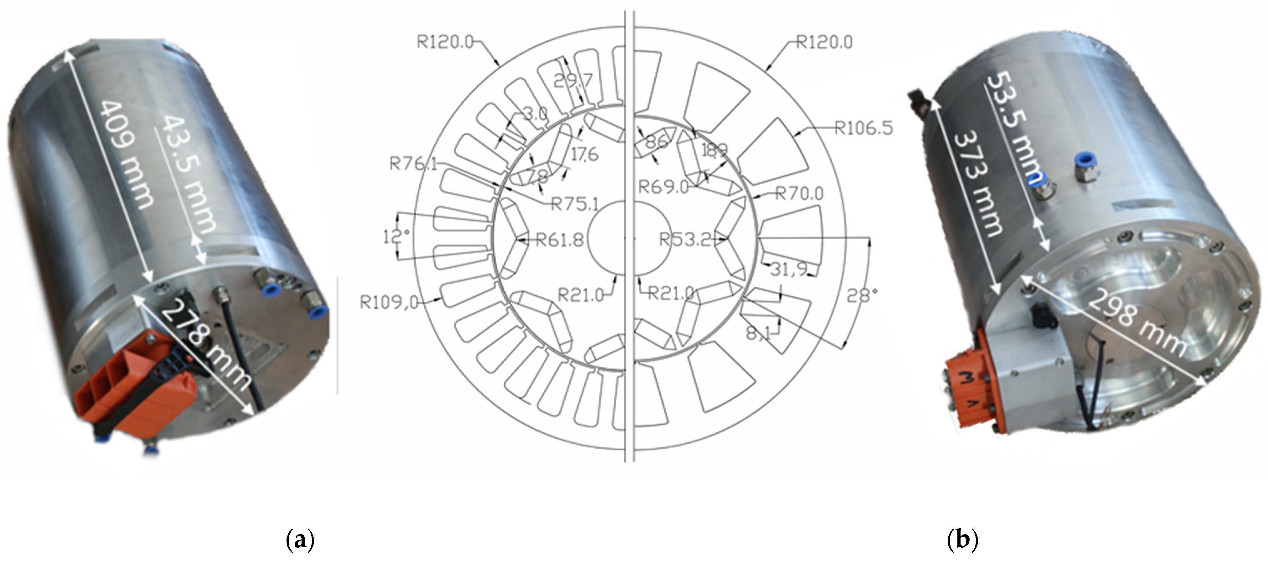
Furthermore, a radial stator with concentrated winding (CW) requires slightly less axial space than an IPM with distributed winding (DW). The final IPM motor size/dimensions resulted from the space envelope imposed by the used propulsion system, as shown in
Figure 2. Both the active diameter ratio and the active length of the analyzed machines were designed to produce required torque. The airgap magnetic field impacts the performance of an electric machine in terms of its electromagnetic torque. Assuming that, in both IPM motors, the outer dimensions of the core are roughly the same, the different topologies of the stator windings may lead to differences in the machine performance, as investigated in this paper.
In both presented prototypes of the radial flux IPM motor with DW and CW, a number of parameters were set, as is typical in most design projects (see
Table 1). These included V-shaped interior PMs, slot/pole combinations of 12/8 and 30/8 for the IPM motor with DW and CW, respectively, and a stator outer diameter of 240 mm. Furthermore, the use of simple rectangular magnet blocks reduced machining costs (there were six magnet segments in the axial direction). The used materials were N38UH Ne–Fe–B for magnets (with an electrical resistivity of −180 µΩ⋅cm), M270-35A electrical steel (with an electrical resistivity of laminated core of −52 µΩ⋅cm), and a copper winding.
The dimensions of the layered steel of the stator and rotor cores of the IPM prototypes are shown in
Figure 2, while
Figure 3 shows the actual cut sheets with marked DW and CW windings. These motor laminations and the angle of PMs were designed to maintain a high electromagnetic torque on a required level and to reduce the cogging torque to an acceptable value. Additionally, it is crucial to properly design the magnetic flux barrier in order to obtain the required flux paths linking the rotor, the air gap, and the stator, as well as to reduce flux leakage to a minimum. The shape of the magnetic flux barrier in the rotor is simple and ensures the acceptable flux density distribution around this barrier. The flux passing through the 1 mm air gap assures a low total harmonic distortion (THD) of the back electromotive force (Back-EMF).
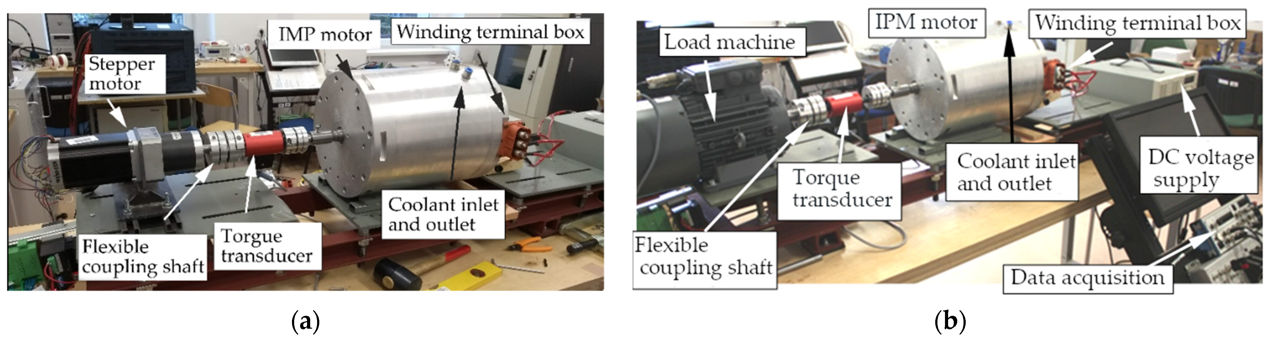
A comparison between the data from the simulation and the experiment involving the Back-EMF, the cogging torque, and the electromagnetic static torque showed a sufficient degree of agreement. The measured IPM motor parameters were compared to the finite element computations (the finite element model is described in the next section). The shaft of the motor prototype was directly coupled with a flexible coupling via an in-line torque transducer, then to the next flexible coupling, and finally to the driving machine (see
Figure 4). The measurements were conducted by a test-stand application with a multichannel high-resolution data acquisition system programmed in LabView.
3. Electromagnetic Finite Element Analysis
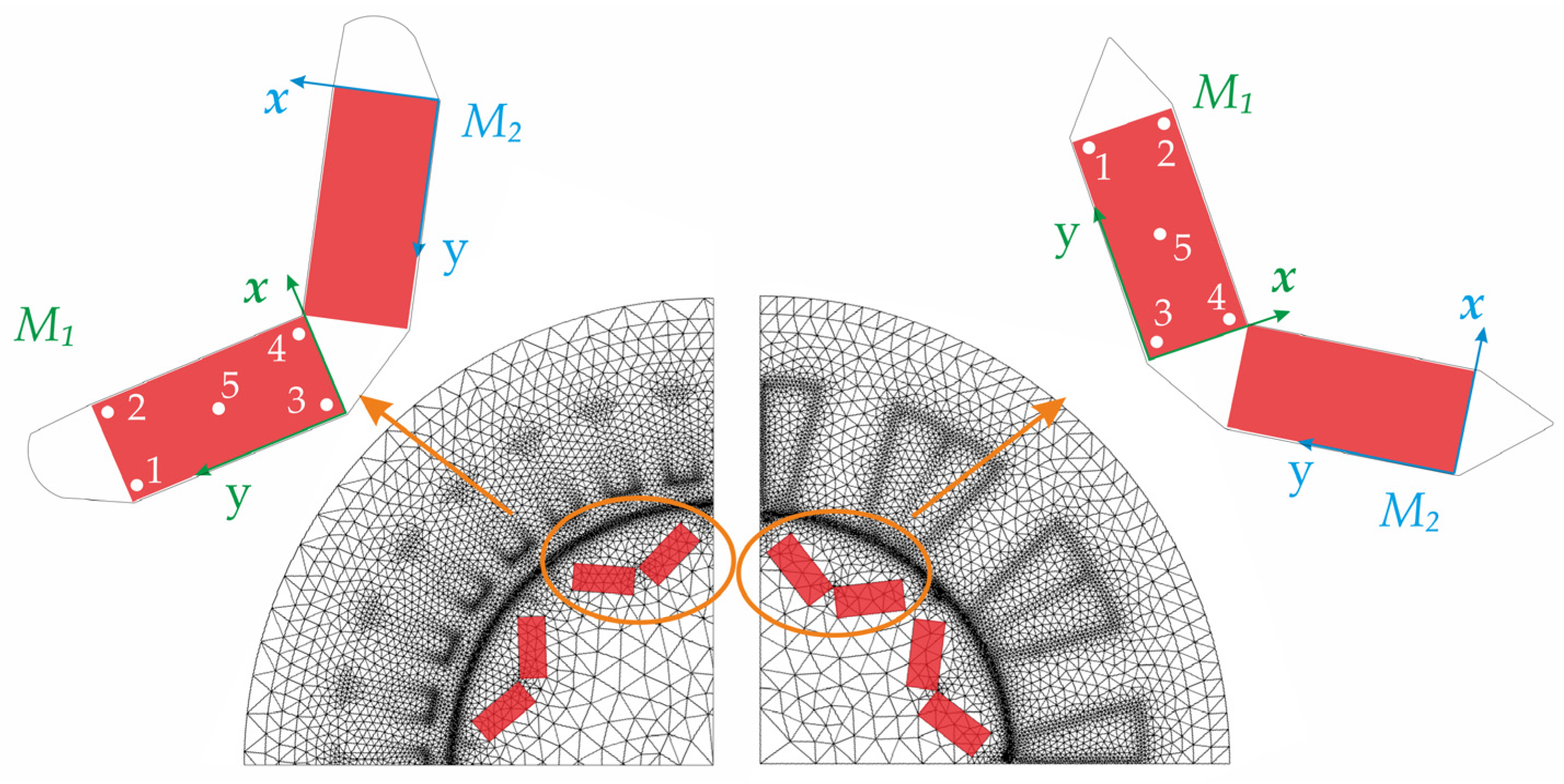
Two-dimensional (2D) magnetostatic and transient numerical models based on the finite element method (FEM) analysis were used to investigate the machine’s parameters. Due to periodic symmetry, only one-half and one-quarter of the complete motor cross-section was modeled circumferentially for DW and CW, respectively.
Figure 5 presents the discretization mesh of numerical models and the orientation of coordinate systems, associated with selected permanent magnets, used in the local forces analysis. A separate section is dedicated to the issue of local magnetic interactions in the vicinity of permanent magnets embedded in the rotor structure, in correlation with the centrifugal force, also under short-circuit conditions. Five points marked on the magnet surface were used in the demagnetization studies for three selected operating points of the considered machines.
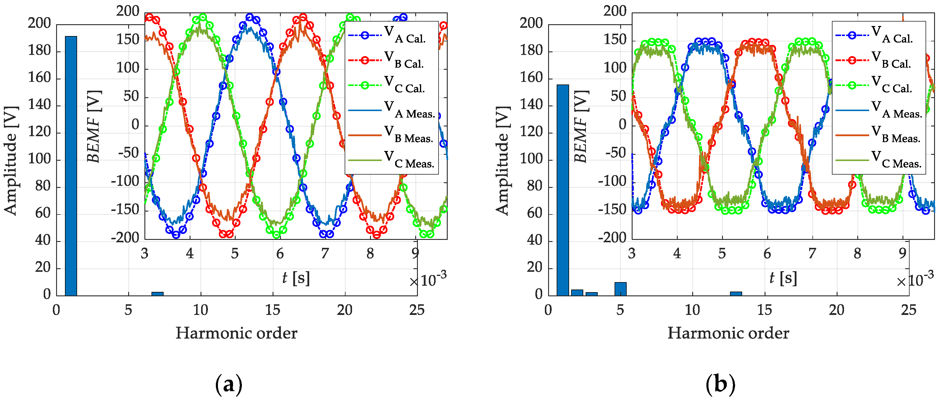
In electric machines, one of the important parameters is Back-EMF. The study began with a comparative analysis of voltage waveforms induced at the winding terminals of both machines for different rotor speeds. During the tests, the voltage waveform induced in the single phase of the IPMs with DW and CW at 4500 rpm was monitored and is presented in
Figure 6. It can be noted that the machine with DW had a slightly higher peak Back-EMF value, and the voltage waveform itself indicated a low harmonic content. In the case of the DW machine, the THD factor was 1.36%, while, for the CW machine, this factor was 7.31%.
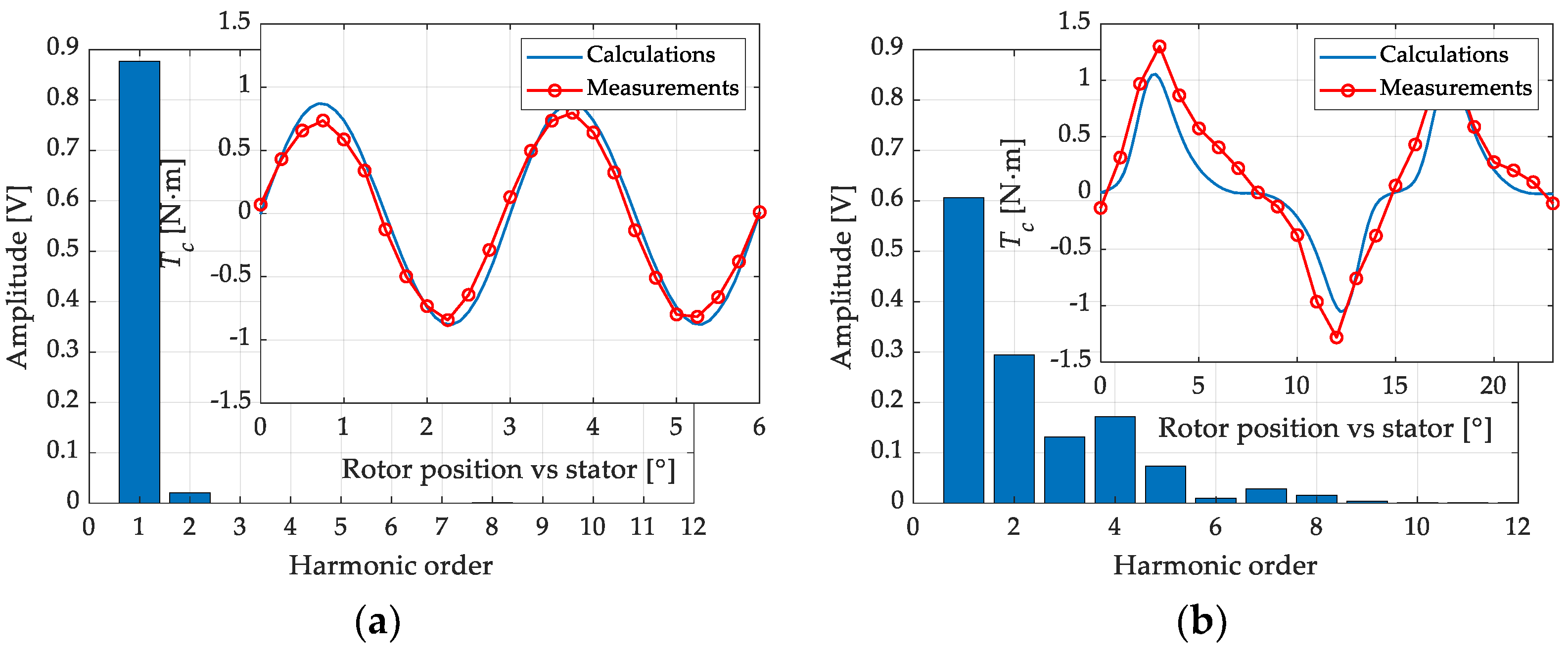
Another important parameter characterizing machines with permanent magnets and influencing the quality of electric drive operation is the cogging torque. In order to make precise measurements of this value, the measuring stand was modified by replacing the AC drive motor (
Figure 4b) with a stepper motor with a planetary gear (
Figure 4a). The measured peak of the cogging torque during the tests was 0.87 N·m and 1.25, while the peak values obtained from the finite element simulations were 0.8 N·m and 1.05 N·m (see
Figure 7) in the IPM with DW and CW, respectively. Additionally, the cogging torque in the CW machine was characterized by a higher THD (61.7%) versus the DW motor (2.38%).
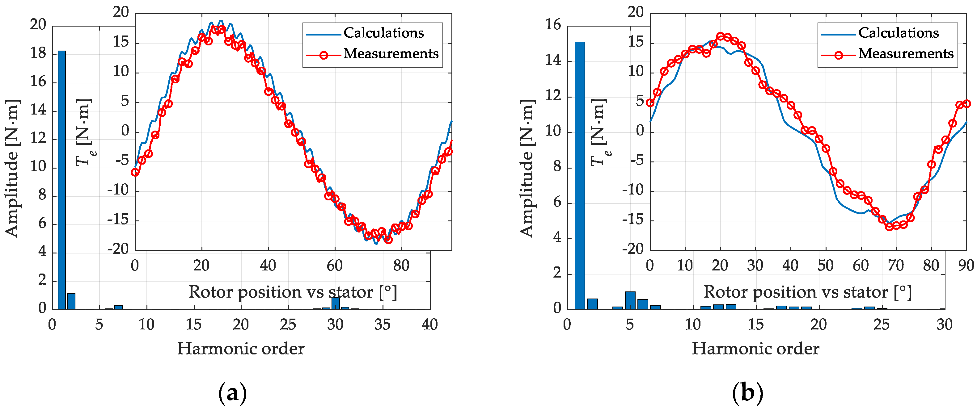
The measuring station presented in
Figure 4 is intended for machines with a power not exceeding 7.5 kW (currently, a new one is under construction, for power up to 100 kW); thus, the torque characteristics were only partially verified. In this case, a significantly higher level of deformation of the torque wave could also be seen for the motor with CW, when compared with the DW motor (see
Figure 8). The FFT analysis for the DW machine clearly showed the presence of the slot harmonic in the spectrum.
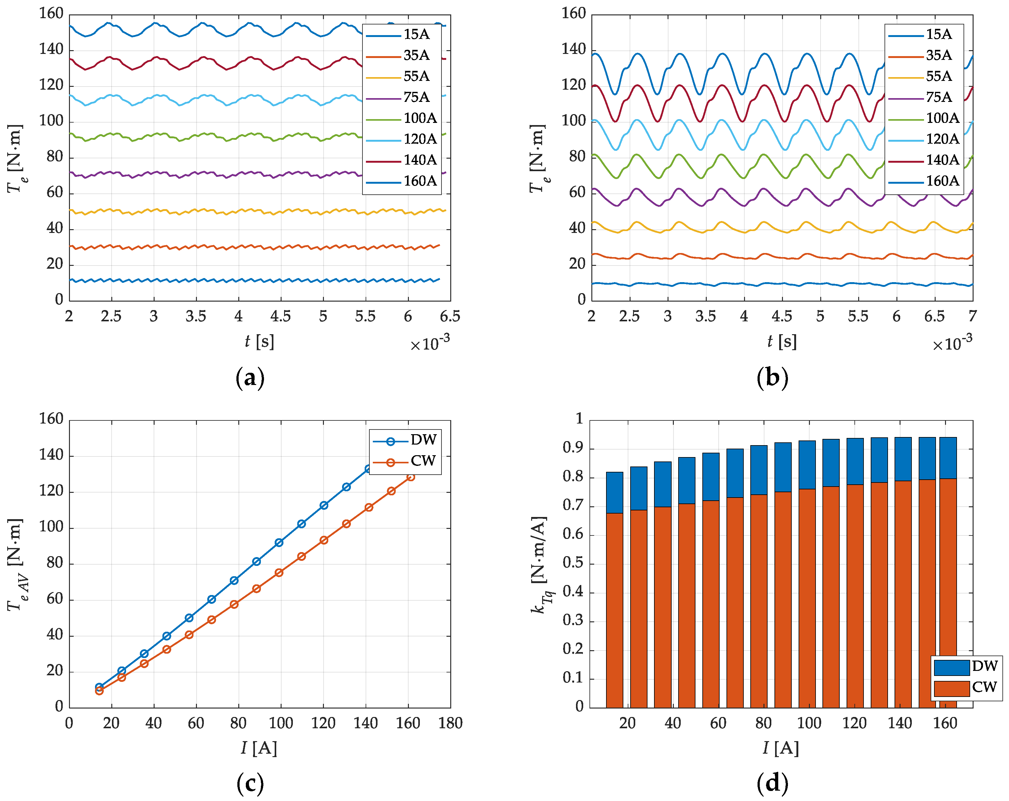
To determine the torque constant, a series of calculations were carried out for the full range of current variations (
Figure 9a,b). On this basis, the dependence of the average electromagnetic torque and the torque constant on the current was determined, clearly showing the advantage of the DW motor (
Figure 9c,d). The torque ripple occurring during the operation of the machine with CW reached a value of 18%, which could cause undesirable effects such as vibrations, dragging, and noise.
From the calculated torque for variable current values, it can be stated that there is no significant saturation of the magnetic circuit in the range of current changes from 10 A to 180 A. Nevertheless, the machine with DW seemed to reach the required torque at lower current levels than the machine with CW.
4. Study on Winding Short-Circuit Fault
When analyzing the designs of PMSM motors intended for electric vehicles, it is also necessary to focus on possible motor damage and motor durability. The number of publications concerning the diagnostics of electric vehicle drives proves that this topic is still important [
39,
40,
41,
42]. Most of those works focused on methods of machine diagnostics in terms of the occurrence of the phenomenon of permanent magnet demagnetization as a result of improper power supply, control, emergency short-circuits, and other unfavorable operating conditions. Many studies are also dedicated to the demagnetization influence on the machine operation [
43,
44,
45,
46,
47]. On the basis of the cited studies, it can be concluded that short-circuits represent the greatest threat to IPM as they may lead to very high peak values of currents. Therefore, it is also worth paying special attention to the short-circuits occurring in the machine at its design phase [
20,
48]. The highest values of currents are obtained in the case of direct phase-to-phase faults in the motor, during which there is a sharp increase in the magnetic field strength in the machine, in losses, and in the temperature in the armature. Therefore, when selecting a temperature class of magnets, the most favorable variant was adopted.
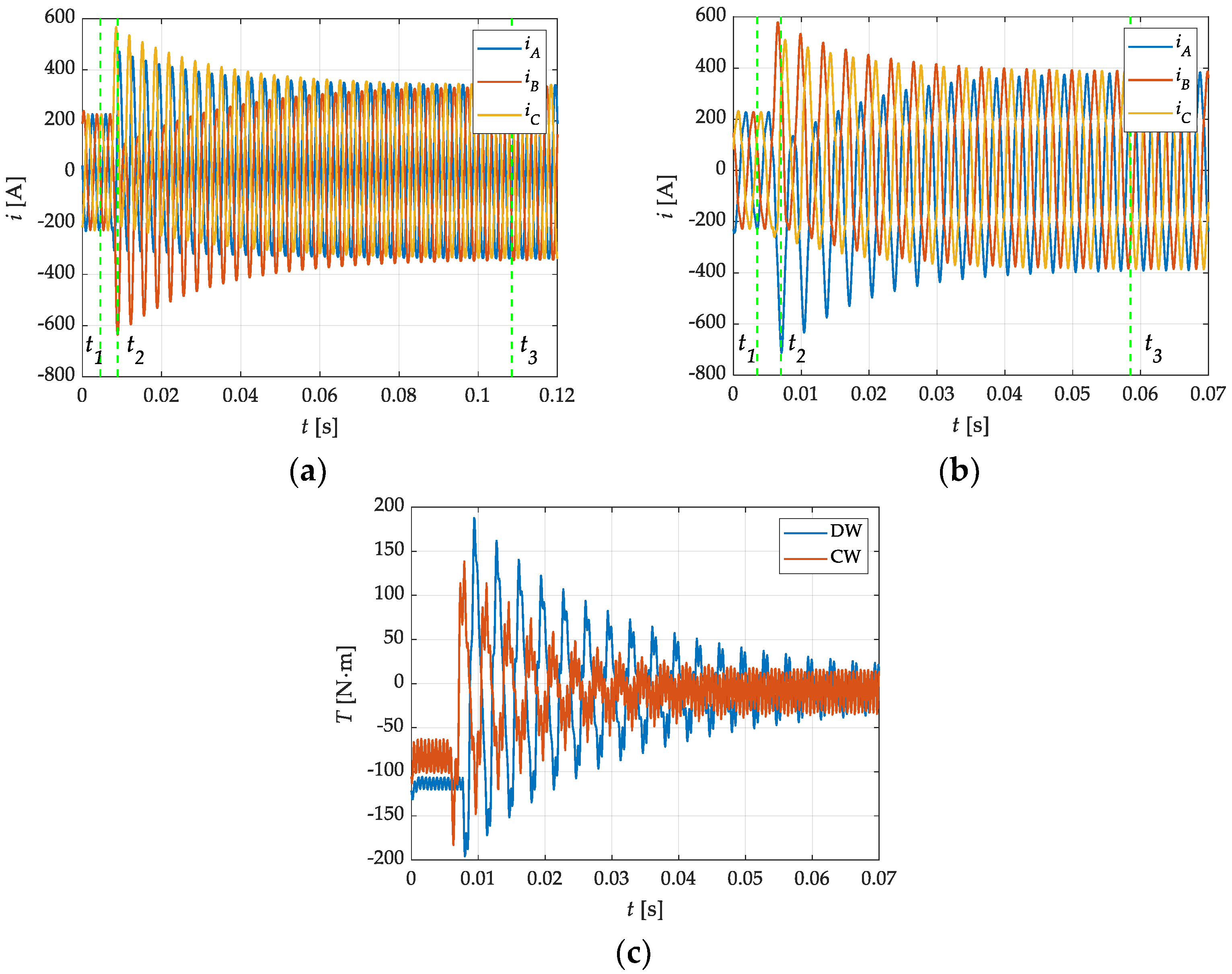
In the tests of transient states, the influence of the armature rotation angle on the obtained maximum current values was taken into account.
Figure 10a,b shows the currents obtained as a result of a short circuit in the windings of the machines operating with the rated load Tl = 125N·m at the speed
n = 4500 rpm. This is one of the most critical fault conditions, because the peak current exceeds the rated current 2.8-fold (DW) and 3.13-fold (CW). Additionally, in the DW motor, the stabilization of short-circuit currents took almost twice as long as in the case of a CW motor. A similar tendency can be noticed in the course of torque waveforms (
Figure 10c). It is worth noting that the DW machine, despite the lower current amplitude at the time (
t2) of the short-circuit, was characterized by a higher torque peak impact when compared to the CW motor. Knowing possible transients occurring during a direct phase-to-phase short-circuit, it is possible to determine the conceivable degree of magnetization of the magnets.
(a) Demagnetization Study
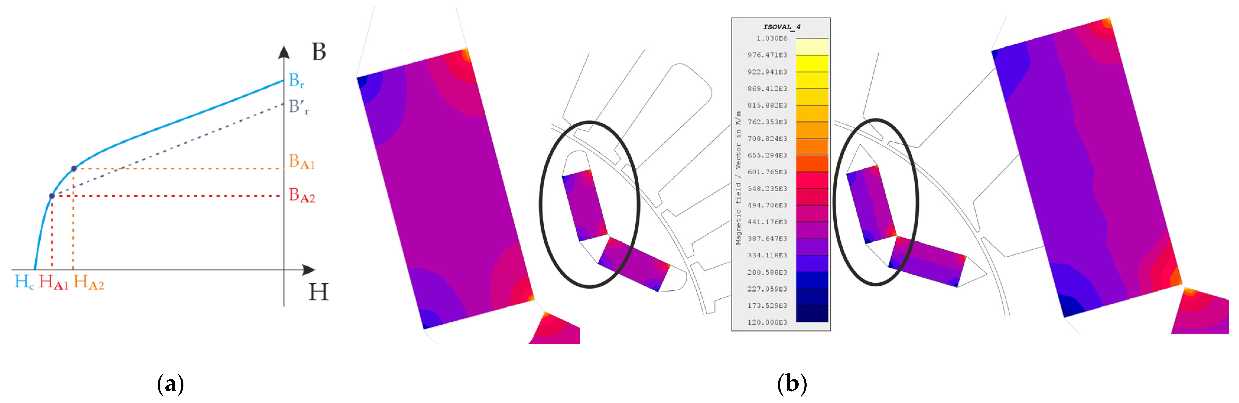
The phenomenon of demagnetization in PM machines is very complex and may have many causes. The magnetic properties of neodymium magnets are strongly related to the temperature. The increase in the PM operating temperature results in a decrease in the magnetic induction in the magnets and, thus, in the efficiency of the entire machine. This problem can be solved by correctly selecting the temperature class of the magnets, but this is associated with a significant increase in costs. It is assumed that an increase in the temperature class by an order leads to a ca. 30% increase in the price of the magnet. Another phenomenon that directly affects the deterioration of the magnet parameters is the presence of a high-intensity magnetic field. On the basis of the B–H curve for a given magnet, the safe working area and the critical point are determined, beyond which the magnet will be damaged. In practice, the aim is for the machine operating point to be selected so that the occurring field strength is in the range from H
A1 to 0, i.e., the magnet works within its rectilinear section of the B–H characteristic. The operating point of the magnet should not pass over the “knee” (
Figure 11a). Exceeding the “knee” means that it is not possible to reach again the B
r remanence induction, and the achievable B’
r value is lower than B
r [
44,
45,
47]. Therefore, when designing an IPMSM machine, it is extremely important to determine the extreme value of the field strength acting on the magnet, associated with the transient short-circuit state.
As already mentioned, the analysis covered the least favorable transition point during a short-circuit (
Figure 10) in which the maximum currents and, thus, the magnetic field occur. This state was considered to be a key factor in the analysis of the risk demagnetization for the magnets in the rotor.
Figure 11b shows the distribution of the magnetic field strength in a pair of magnets for both machines (DW and CW).
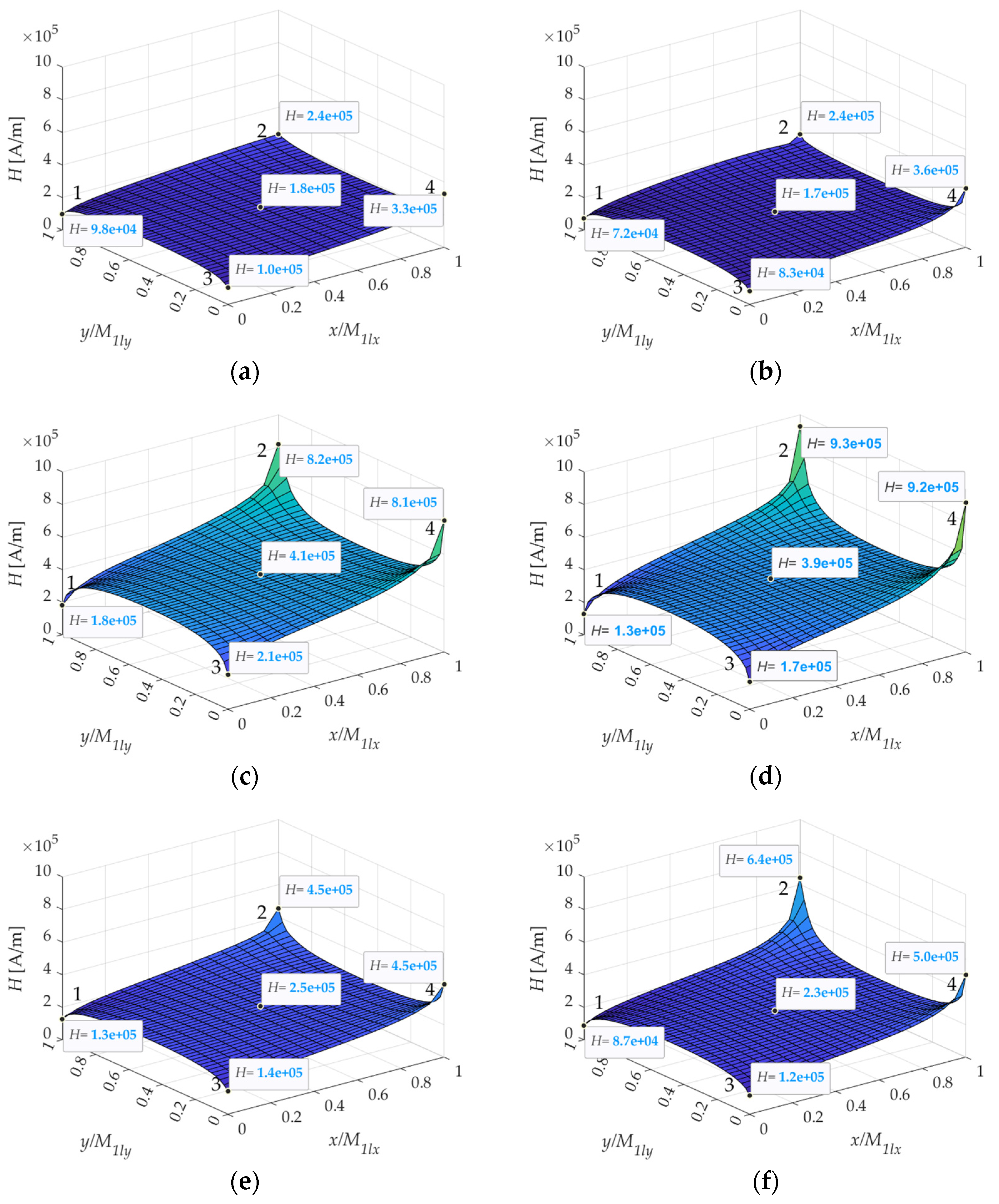
A detailed analysis of the magnetic field in the magnets was performed at three non-randomly selected time moments, also marked in
Figure 10. The magnetic field in the M
1 magnet was analyzed in sequence before a load collapse (
t1)—
Figure 12a,b, then for the highest peak value during the short-circuit (
t2)—
Figure 12c,d, and at time (
t3), after the short-circuit currents were stabilized—
Figure 12e,f. On a basis of the graphs shown in
Figure 12, it can be noticed that magnet areas most exposed to demagnetization were positioned in the corners—points 2 and 4. It can also be seen that the CW machine was characterized by slightly higher field values at the magnet corners, by about 13.4%. The presented results show that the applied magnets were not exposed to demagnetization in such a situation. It is possible to use magnets of a lower temperature class, SH or even H, for which the risk of demagnetization concerns about 1.5–2% of the entire magnet volume, with the assumed operating temperature of the winding of up to 120 °C. As previously mentioned, it is assumed that an increase by one temperature class is associated with a 30% increase in the magnet price, and this is one of the most important aspects from the serial production perspective. Nevertheless, it is important to note that, during the normal operation of electric or hybrid vehicles, the motors may be overloaded for 15, 30, or even 60 s. In this case, it can be concluded that using a magnet of a higher temperature class is reasonable.
(b) Magnetic Forces on Magnets
One of the most important aspects to consider when designing an IPMSM, which is often neglected in the scientific literature, is the analysis of forces acting on magnets. This information is important at the stage of construction of the machine itself, where aspects related to manufacturing and assembling tolerances [
31,
32,
33,
34], as well as their impact on the operation, are frequently overlooked. The manufacturing tolerance is of particular importance in the case of surface-mounted magnets, less in the case of recessed mounting, but the knowledge of local influences allows unambiguous determination of the position of individual segments forming a pole immediately after assembly. For obvious reasons, due to clearances, permanent magnets are subject to different effects in the case of a rotor alone (Var. 1.), and the distribution of local forces changes when they are placed in the stator (Var. 2.).
Table 2 shows the forces acting on the magnets in the rotor, in all configurations. These forces were related to local coordinate systems (see
Figure 5), defined at the corners of the individual magnets. Due to a symmetrical design of the machines, only one pole (two magnets) was analyzed in the further part of this study.
When the rotor is installed in the stator, local force values decrease significantly due to the change in reluctance in the rotor–airgap–stator path. In this case, the value of the force acting on a selected magnet depends on a position of the rotor in relation to the stator. Therefore,
Table 2 also includes the variability of these interactions. In the case of the DW machine, due to a large number of slots, the local forces do not change much, while with the concentrated winding (CW), much larger fluctuations in the local forces can be observed.
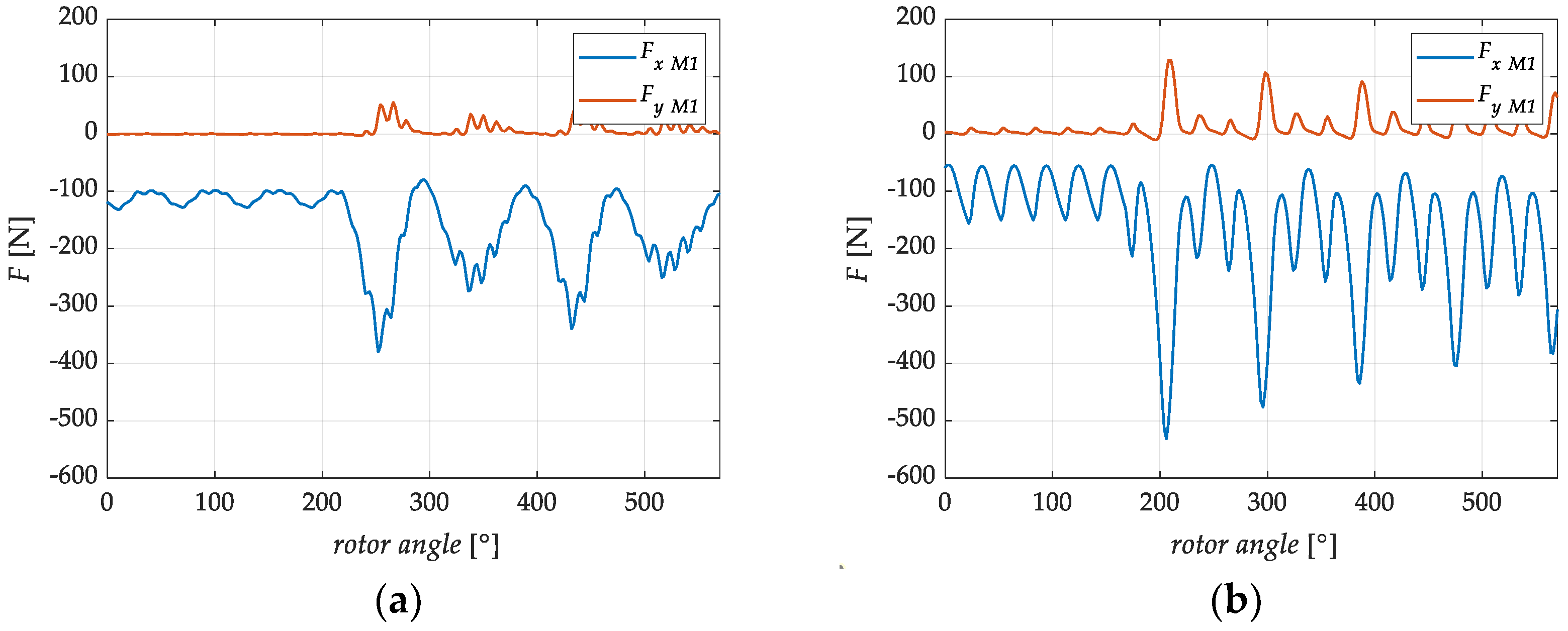
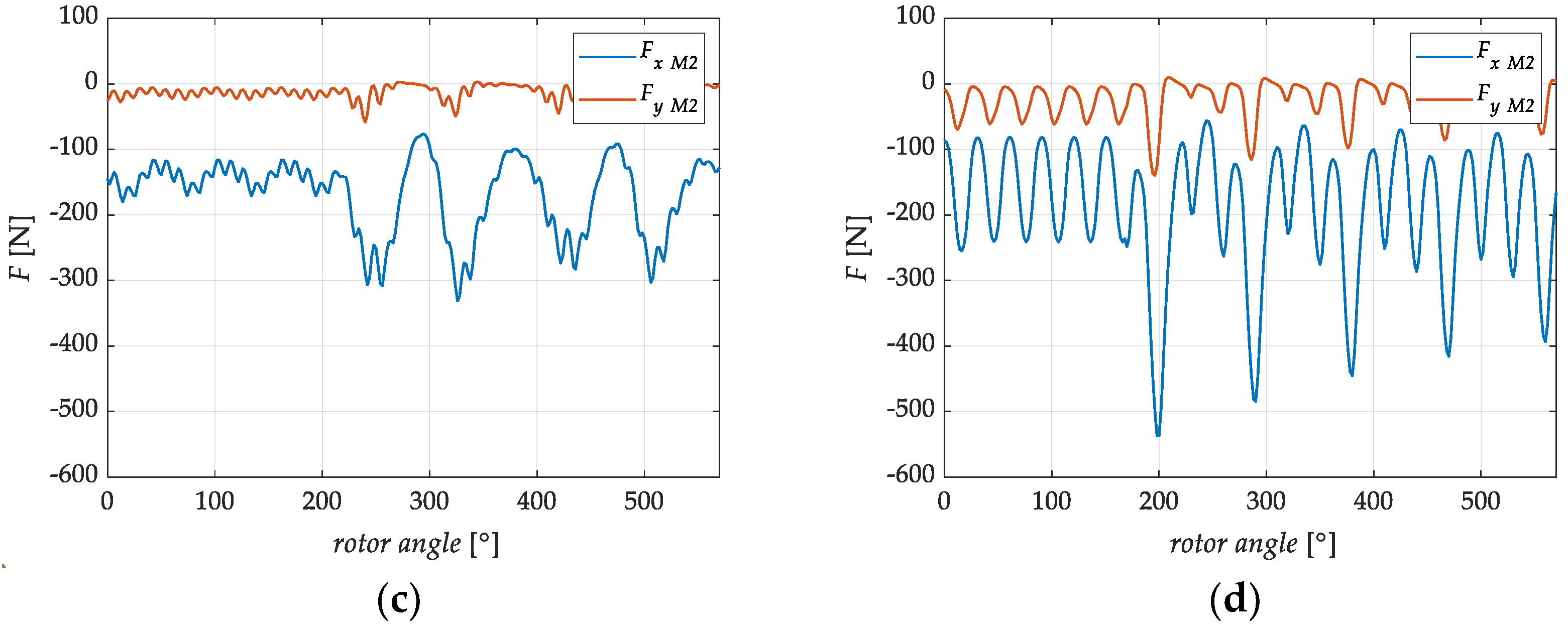
The distribution of forces acting on magnets in a nonpowered machine is closely related to the assembly tolerance. A separate aspect is the distribution of forces acting on selected magnets in the machine’s operating state.
Figure 13 shows forces acting on magnets during operation under rated conditions and during a three-phase short-circuit. On the basis of the obtained relations, it can be seen that the forces acting on magnets M
1 and M
2 aligned in a V-shape are different.
During normal operation, the Fy components acting on M1 magnets are close to 0, while, for M2, they are subject to slight oscillations, resulting from the direction of rotor rotation. For the opposite direction, the Fy component for M2 magnets will be close to 0. The factor influencing the force Fx value for magnets is the value of the machine load angle. With an increase in the load, the value of the component also increases. It can also be seen that the forces acting on the CW machines are characterized by significantly greater oscillations than those observed in the case of the DW machine.
During the transient state accompanying a three-phase short circuit, amplitudes of the individual components of the local forces increased significantly, as expected. In the case of the DW machine, the Fy component of the M1 magnet increased more than 50-fold. In both cases, for the DW and CW machines, up to a sixfold increase in the Fx component can be seen. In all cases, the signs of Fx components for the discussed magnets suggest their movement inside the rotor.
(c) Magnetic Interactions and Centrifugal Force
The rotor of any rotating machine is subject to a centrifugal force. As is well known, in this respect, the rotor diameter and the developed rotational speed are of particular im-portance. The considered designs of IPM machines were designed at 4500 rpm. A complete analysis of local magnetic interactions in the area of permanent magnets also requires taking the centrifugal force into account. Technological considerations always involve a certain tolerance of the magnet dimensions and the axial steel laminate. When considering the emergency states (short-circuit states) and the associated large fluctuations of forces acting on permanent magnets, it is also worth taking the centrifugal force into account. A possible magnet movement is always associated with potential damage; therefore, it is necessary to fill empty mounting spaces with epoxy resin. However, inaccurate filling can potentially lead to the magnet displacement.
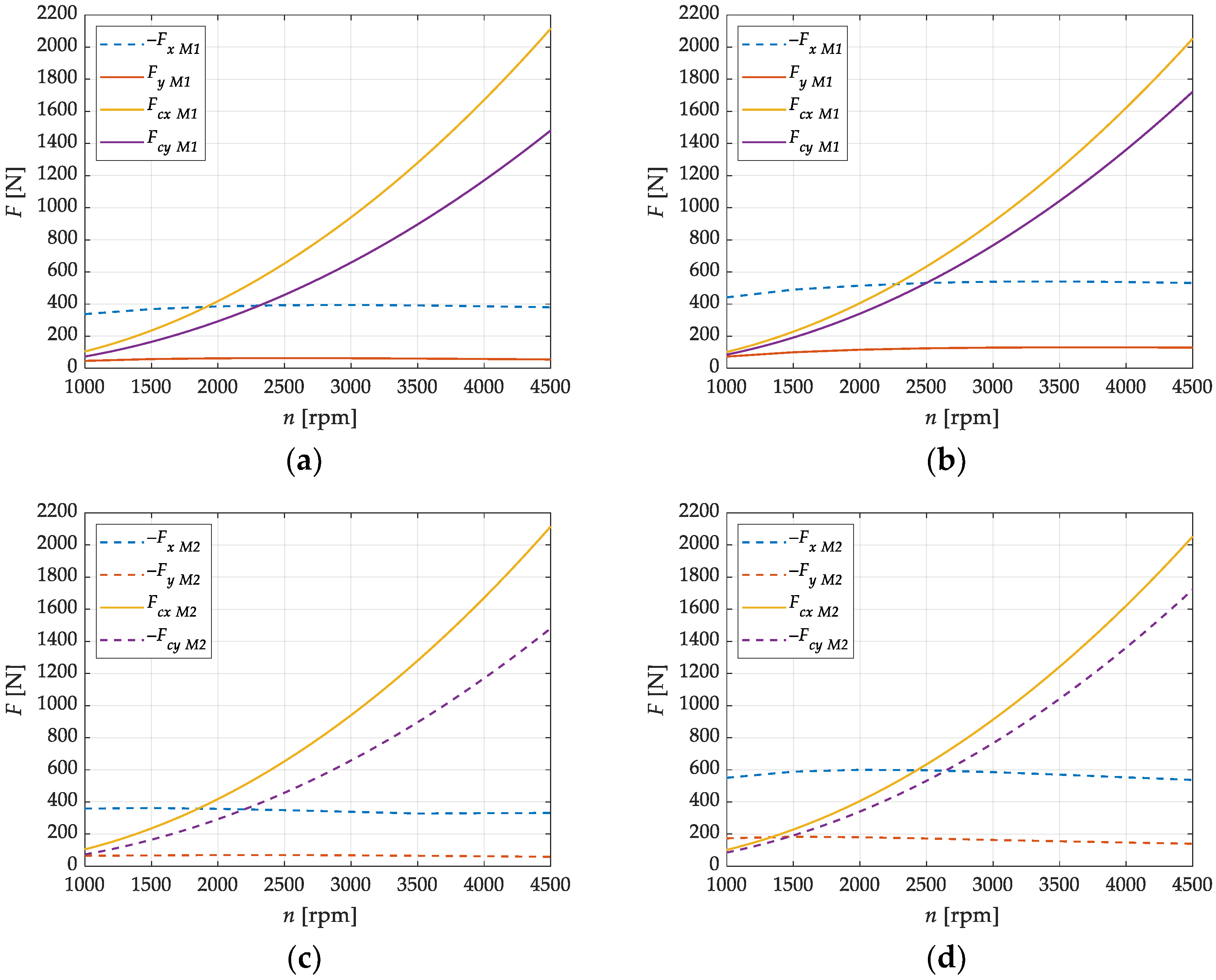
In this part of the discussion, the authors decomposed the centrifugal force into components related to the local coordinate system of the M
1 magnet (
Figure 14). The extreme peak value was determined for components
Fcx and
Fcy (
Figure 13) on the basis of an analysis of the characteristics describing their angular variability at different rotational speeds at maintained constant power. The comparison of the individual components of the magnetic forces and the centrifugal force is shown in
Figure 14. Analyzing the graphs, it can be seen that it is possible to move the magnets (M
1 and also M
2) during machine operation, especially along the
x-axis of the local coordinate system. Both the fluctuations in the magnetic forces associated with the change in load and the change in rotational speed of incorrectly attached magnets can lead to vibrations. The problem of displacement along the
x-axis disappears after exceeding a speed of about 2000 rpm for the DW machine and 2500 rpm for the CW machine. The situation is definitely different along the
y-axis of the local coordinate system. In all cases, the direction of the local magnetic force and the
Fcy component of the centrifugal are the same, forcing a shift of the magnets toward the flux barrier. Leaving too much clearance on the side of the flux barriers may cause uncontrolled displacement of the magnet toward the rotor surface, thus also changing the distribution of the magnetic flux.
5. Conclusions
Synchronous machines with permanent magnets have already become a part of modern drive solutions used in electric and hybrid vehicles. The factors contributing to the electric drive popularity are primarily its high efficiency, good performance, resistance to damage, and reliability, as well as a favorable ratio of power and volume to production cost. Accepting the necessity of using critical elements (neodymium magnets), an attempt is often made to optimize costs by modifying the winding. This study is based on two designs of machines with different types of windings (DW and CW), built with an electric vehicle in mind. A significantly shorter length of the end windings, lower resistance and copper losses, and easier heat dissipation, also in addition to lower winding costs, undoubtedly represent advantages of the CW machine. At the other extreme, however, parameters such as the content of higher harmonics in Back-EMF, the electromagnetic torque, the cogging torque, or the torque constant, which are more favorable for the DW motor, should be considered. On the basis of these criteria, it is very difficult to clearly determine which machine is more advantageous. With this in mind, the authors of this paper looked in more detail at the key characteristics of currents and the electromagnetic torque also during critical transient states during a short-circuit. The current waveforms shown in the characteristics not only have effects manifested in the machine thermals, but, in combination with the torque surge, can also often lead to permanent damage to the drive.
One of the key issues is the problem of the shortened life of permanent magnets, as it depends on both the temperature and the point of strong demagnetizing fields. On the basis of the results of the calculations presented in
Section 4(a), it was shown that the magnets in the CW motor are slightly more prone to demagnetization. The key parameter in this respect is revealed to be the instantaneous short-circuit current value, which is higher for the CW design. The analysis of decay time of the transient component, increasing the values of the currents and the torque, shows that the unfavorable transient state lasts much longer in the DW machine. The global effects in both cases affect the point accelerated degradation of permanent magnets in a similar way. Therefore, this issue may also be the subject of optimization considerations regarding the geometry and type of the permanent magnet.
Another aspect, which is rarely discussed in the scientific literature, is the analysis of local magnetic interactions within embedded magnets, presented in this paper. The predicted clearance in the fit of the elements and the tolerance of the sheet metal package and permanent magnet segments always lead to some differences between the model and the prototype. While in the case of machines with recessed magnets, differences in the magnets arrangement in the rotor have little effect on the image of the magnetic field, the very possibility of their movement may be the problem. As the analysis in
Section 4(b and c) shows, permanent magnets are placed differently in the mounting holes at the stage of building a standalone rotor and differently when the rotor is assembled and centered in the stator. Relevant knowledge in this area will enable appropriate adjustments at the machine construction stage. The authors did not find an analysis of the forces acting on permanent magnets during short-circuits in the literature. The presented analyses show that the lack or inadequate securing of permanent magnets by gluing may lead to local displacements and possibly also to damage. The DW machine appears to be a more advantageous solution, due to lower amplitudes of changes in the components of local magnetic forces. Taking also the centrifugal force into account, it is possible to approximate the limit rotational speed (about 2000 rpm and 2500 rpm for the DW and CW motor, respectively), above which the local magnetic interactions are completely leveled.


