
Model Predictive Control with Modulator Applied to Grid Inverter under Voltage Distorted
by
 ,
,
Angelo Lunardi
1,2,†, 
Eliomar R. Conde D
2,†,
Jefferson de Assis
3,† ,
,
Darlan A. Fernandes
3,† and
Alfeu J. Sguarezi Filho
2,*,† 1
University of São Paulo, São Paulo 05508-010, Brazil
2
Federal University of ABC, Santo André 09210-580, Brazil
3
Federal University of Paraíba, João Pessoa 58051-900, Brazil
*
Author to whom correspondence should be addressed.
†
These authors contributed equally to this work.
Energies 2021, 14(16), 4953; https://doi.org/10.3390/en14164953
Submission received: 15 June 2021
/
Revised: 5 July 2021
/
Accepted: 19 July 2021
/
Published: 12 August 2021
(This article belongs to the Topic Power System Modeling and Control)
Abstract
:This research paper presents a model of predictive control with a modulator for the inverter linked to the electrical grid, using the stationary reference frame and operating under grid distorted voltage. The stationary reference frame model for the system is obtained in its fundamental frequency and then the model predictive technique is implemented, which predicts the system actions using the obtained system model without the need of any other harmonic consideration. The controller calculates the voltage vector of the inverter through the minimization of the cost function. Thus, the proposal demonstrates, through experiments, its positive results regarding the low impact of the distorted voltage in the grid current without using any harmonic consideration on the model. Experimental results and comparisons carried out endorse the proposal of this work.
1. Introduction
Various countries have increased their usage of renewable energy sources due to the concern about emissions [1]. In this context the inverter connected to the grid can perform the connection between the renewable energy system and the electrical grid in several ways, as distributed generation (DG) systems [2].
Due to the employment of the power electronics converters, such as DG and electronics loads, the voltage can be distorted [3]. In this way, several controllers, such as resonant [4] or proportional plus integral considering harmonics [3,5], were proposed to mitigate the distortions.
In [6], they used a resonant control approach with a dual-loop current for a grid-connected inverter, which is based on a model of grid with LCL-filter between inverter and grid in discrete domain under a stationary frame. The paper work presents the practicality and robustness, but it is not clear that this controller is capable of mitigating some voltage distortions because the author focused on designing a robust controller.
Another solution that can be considered is to not only use a proportional controller with resonant, but an integral part that can also be added to obtain zero steady-state error [7] and a sinusoidal current. The mentioned solutions can obtain interesting results, they can degrade their performance due to the non-well tuning of the gains in the design and when the harmonics components enhance, again the author does not apply this controller under voltage distortions, due to this, the contribution of this article is presenting a controller technique to mitigate the distortion on the grid current caused by voltage distortion.
The authors in [8] propose a controller in the stationary frame for a voltage source inverter (VSI) operating under distortion and unbalanced grid voltage. The controller is based on the grid fundamental component with a proportional-resonant (PR) [9], and the implementation in a stationary frame avoids using a phase locked loop (PLL) as the controller proposed in this article.
The model predictive control (MPC) is a class of controllers that predicts the system action by means of its model and calculates the input by means of a minimized cost function [10].
The finite control set (FCS) for the grid connected inverter operating under voltage distortion, and using a moving average PLL was presented in [11], the authors also chose the stationary frame to control the system [12].
The FCS is a specific type of controller, compared to the predictive controller, the main difference is that it has a limited number of voltage vectors which the controller can choose [13]. Thus, the results obtained with this type of controller present a variable switching frequency that interferes with the projected of filters for grid-connected, and there is no robustness against distortions on the grid [14].
The paper [15], which proposes to mitigate the degradation of THD in the input currents by active front end (AFE) rectifiers under voltage distortion thought a model predictive virtual flux control (MPVFC). the controller is based on the cost function on virtual fluxes, that it is robust to voltage distortion.
Another solution to reduce the THD of grid current and output power, the authors in [16] proposes a model predictive direct current control (MPDCC) for a three-level T-type rectifier. If we compare this controller with the conventional method, the microcontroller is responsible for computing the instantaneous reactive power and active power; using a PLL, the positive and negative sequence is extracted. The article also provides the experimental results to support the feasibility and effectiveness of the proposed MPDCC strategy.
An MPC with modulator solves the problem of switching frequency presented in FCS, which consists of using a pulse width modulation (PWM). In this context, this technique has been proposed to induction motor drives [17], doubly-fed induction generator [18] or inventers [19]. However the tests are made in grid voltages without disturbances, it is commonly find this controller with modulation applied in power electronics, which provides a fixed switching frequency for the system [20]. MPC plus repetitive controller with modulator operating under voltage distortion for DFIG is presented in [21], the article proposal links the predictive control behavior to the repetitive in one controller, where the repetitive controller is designed to track the reference signals and reject possible disturbances in the DFIG.
This paper [22] proposes a grid-voltage sensorless MPC method for the control of PWM rectifier. Different other controller techniques for power control, this controller uses extended reactive power to cope with the unbalanced grid voltage. Moreover, the virtual flux is used to achieve grid-voltage sensorless operation and can work effectively even under voltage distortion. A second-order generalized integrator quadrature signal generator (SOGI-QSG) in combination with a cascaded delayed signal cancellation (CDSC) block is responsible for an estimation of the virtual flux. The equation of state is different from conventional controllers and work with the virtual flux, increases system complexity when compared to FCS.
The proposal of this paper introduces the current control of an inverter connected-grid using MPC with modulator operating when the grid voltage has harmonic distortions, this control technique is a different method to project a predictive controller. The controller predicts the components of the grid current vector action by means of its discrete state-space model in its fundamental frequency. The minimized cost function calculates the voltage vector of the inverter. In this context, the proposal permits to inject grid current in accordance with the standards as IEEEStd 1547.2-2008 [23] even in voltage distorted. The results obtained in experimental setup endorses the proposal.
2. Modeling of the Grid-Connected Inverter
The power inverter links the grid using an inductive filter. In this context, the inverter is modeled as voltage source with variable frequency and amplitude. The inductor presents a behavior as voltage due to the inductance and internal resistance as in the following equations [24].
The grid voltage in stationary reference frame in (1), can be represented in discrete form in sampling time employing the zero-order-hold (ZOH) technique without delay and it can be written as follows [25]:
where and are the inductance and internal resistance of the filter, current vector, voltage vector, related to the grid, related to the inverter, and represent the components of the real and imaginary axis of the vector, and are the grid voltage vector components and is the identity matrix.
Filter can be calculated using the following expression, the filter is an important part of the system because is capable to filter some high-frequency noise in the current grid signal. [26].
where represents the switching frequency, expresses the effective value of the mains voltage, and represents the current variation in the inductor.
3. Current Grid Control Using the MPC
The MPC predicts the future actions of the system plant and one calculates the input using the cost function minimization. Additionally, it permits to insert the restrictions. In the proposal presented in this paper the system is modeled at fundamental frequency and the MPC must be able to reject the disturbance. Hence, the inverter can operate with no distortions in grid current. In this context the disturbance will be voltage distortions due to harmonic components.
The prediction of the components of the grid current vector can be performed as [27,28]:
where
where means the prediction horizon of the grid current, is the prediction of the grid current vector, .
The quadratic cost function in matrix representation is given by:
where represents the grid current vector future references, weighs the controlled grid currents (outputs) and their predictions, weighs the control efforts of inverter voltage minus grid voltage vectors, is the input, is the control horizon and due to the components of the vector representation.
The expression of the minimized of the cost function (Equation (10)) can be represented algebraically from and and isolating . Hence, the representation is given by
In this paper it is assumed that . In this case, the is minor then the period of the grid time.
The elements and of the grid current vector references in the fundamental frequency can be performed using the grid active and reactive power references and the fundamental frequency of the grid voltage vector components as follows [29]:
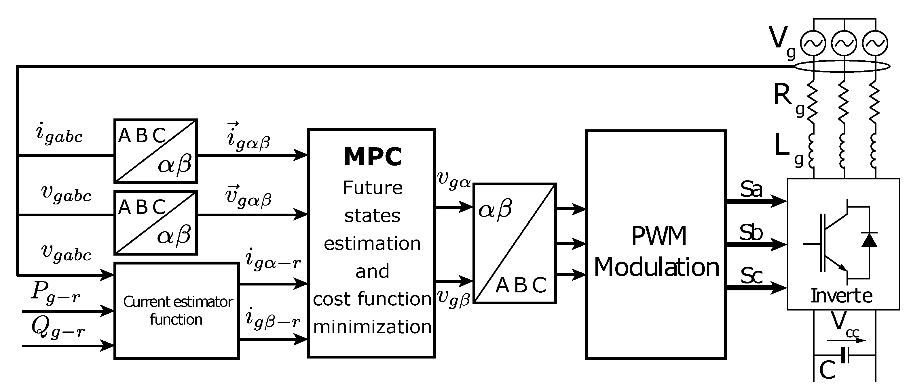
The grid current vector control using MPC calculates the voltage vector of the inverter in stationary reference frame using Equation (11) considering the value of the grid voltage vector components in fundamental component frequency. This voltage vector is the input of the PWM algorithm as space vector modulation. In this way, the grid current will reach their references. The Figure 1 depicts the block diagram representation of the scheme Rossiter [30].
MPC needs the information about the angle and the fundamental frequecy component of the grid to compute the appropriate voltage vector of the inverter to operate during grid voltages. In this context, the PLL based on grid voltage, like the one in [31] can operate under distorted voltage due to harmonics elements. Another possibility is to use the PLL presented in [32]. The PLL is inside the block current estimator function in Figure 1.
4. Results Obtained in Experimental Setup
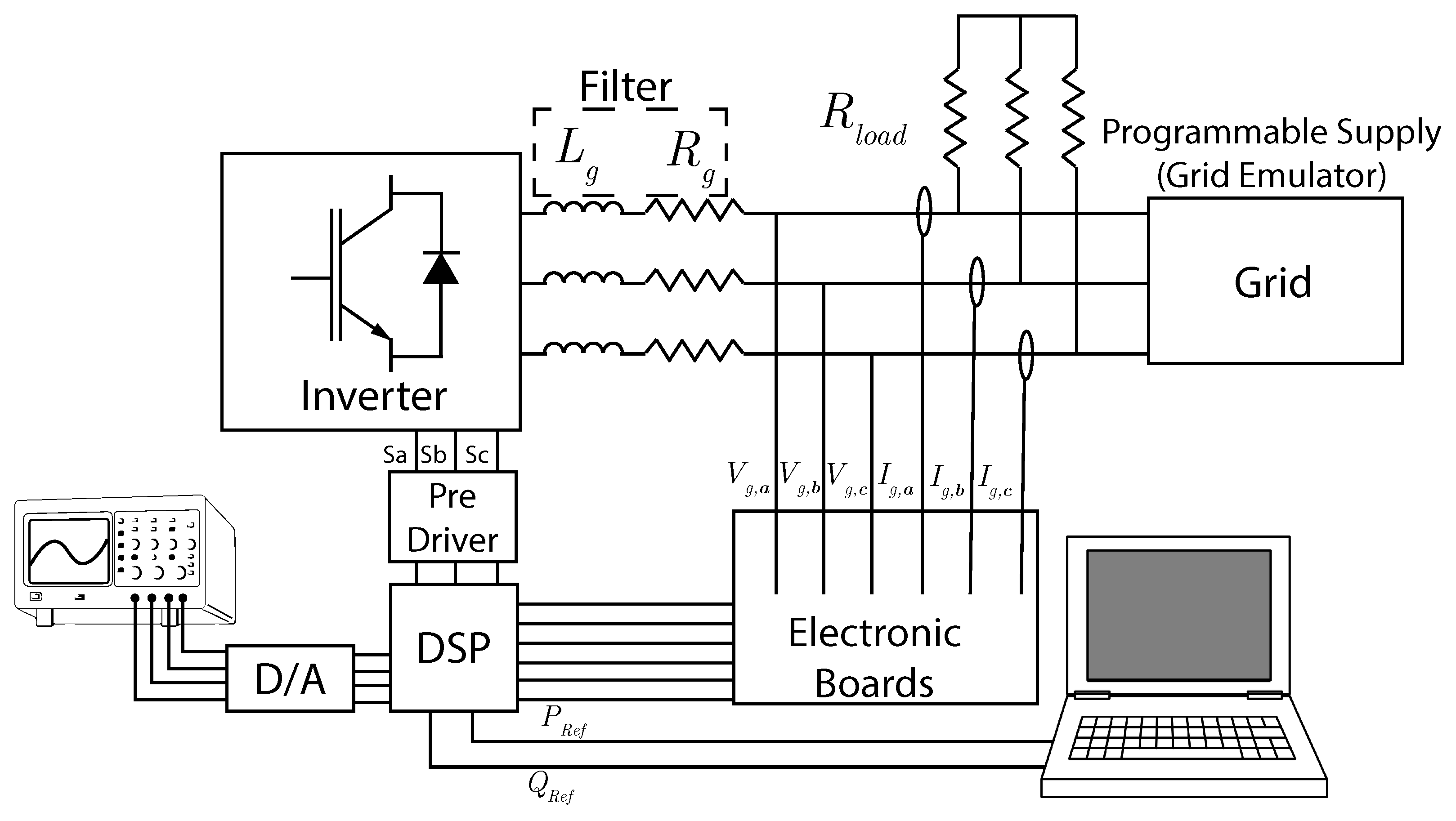
The proposed grid current control using MPC strategy were tested based on the experimental setup in accordance with Figure 1. This mentioned set is composed of electronic boards to acquire the voltage (v) and current (i) variables, a digital signal processor (DSP) Texas Instruments model TMS320F28335, inductor bank, and a controllable electronic voltage source that acts as the electrical power grid, and also provides the distorted voltage, and the Figure 2 presents the experimental bank setup. The parameters of the system is presented in Table 1, it provides also the weighting factors that were chosen based on the FARE-based weighting matrices approach [27].
To test the performance of the proposed grid current control using MPC, the voltage of the electrical grid chosen is the same of [21] which is a variation of the distorted grid used in [33], this grid is distorted by 3.94% in 5th, 3.15% in 7th, 2.36% in 11th, 1.50% in 13th, 1.10% in 17th and 0.70% 19th harmonic components, as presented in Table 2.
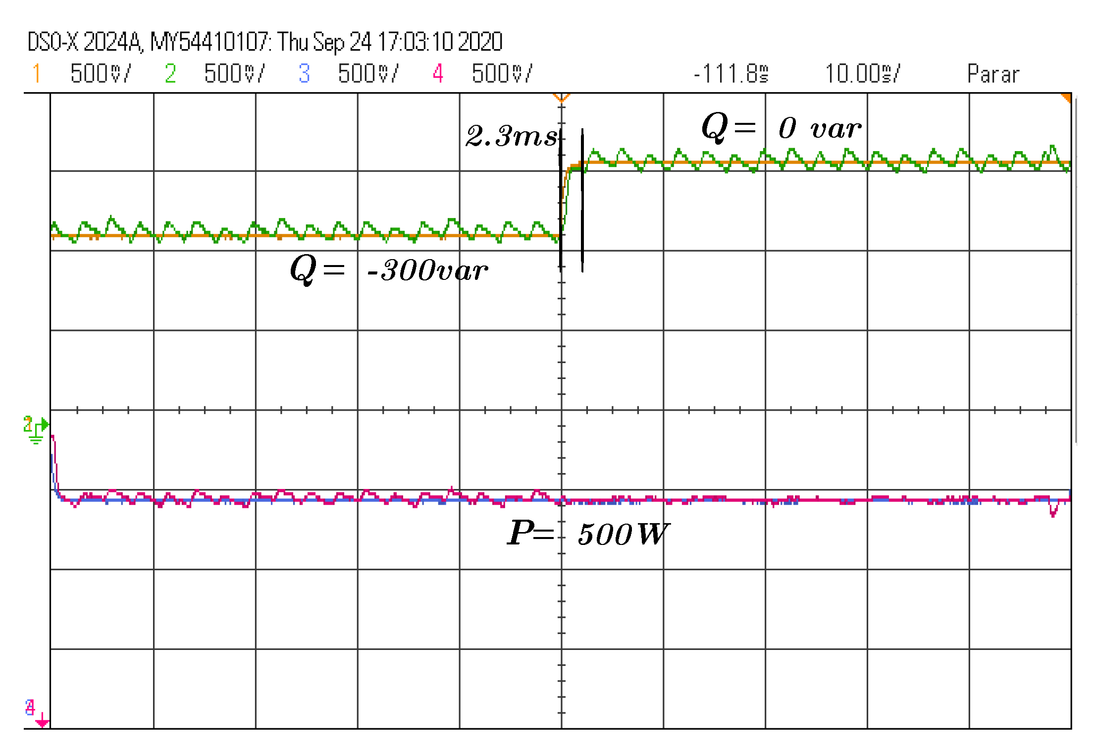
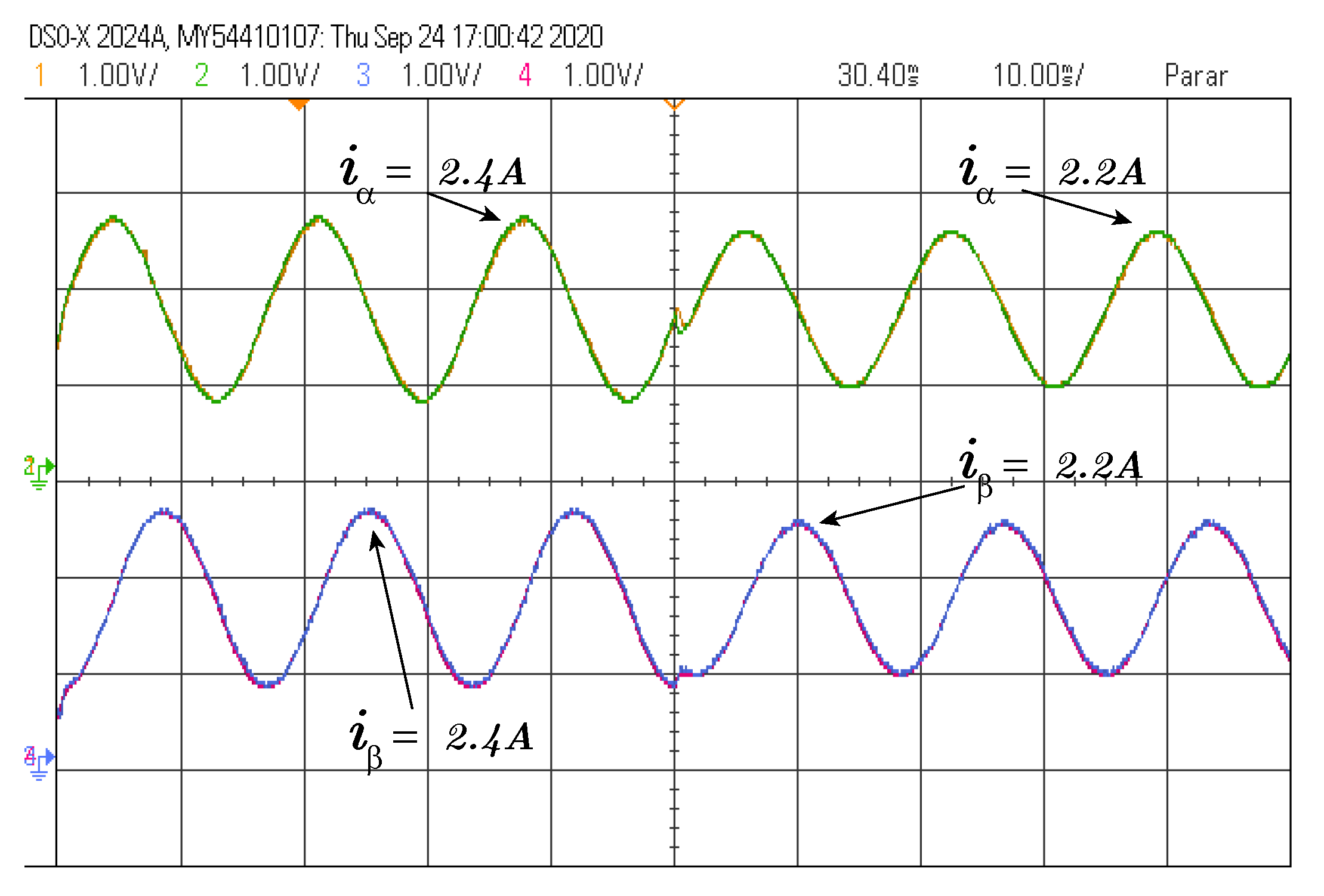
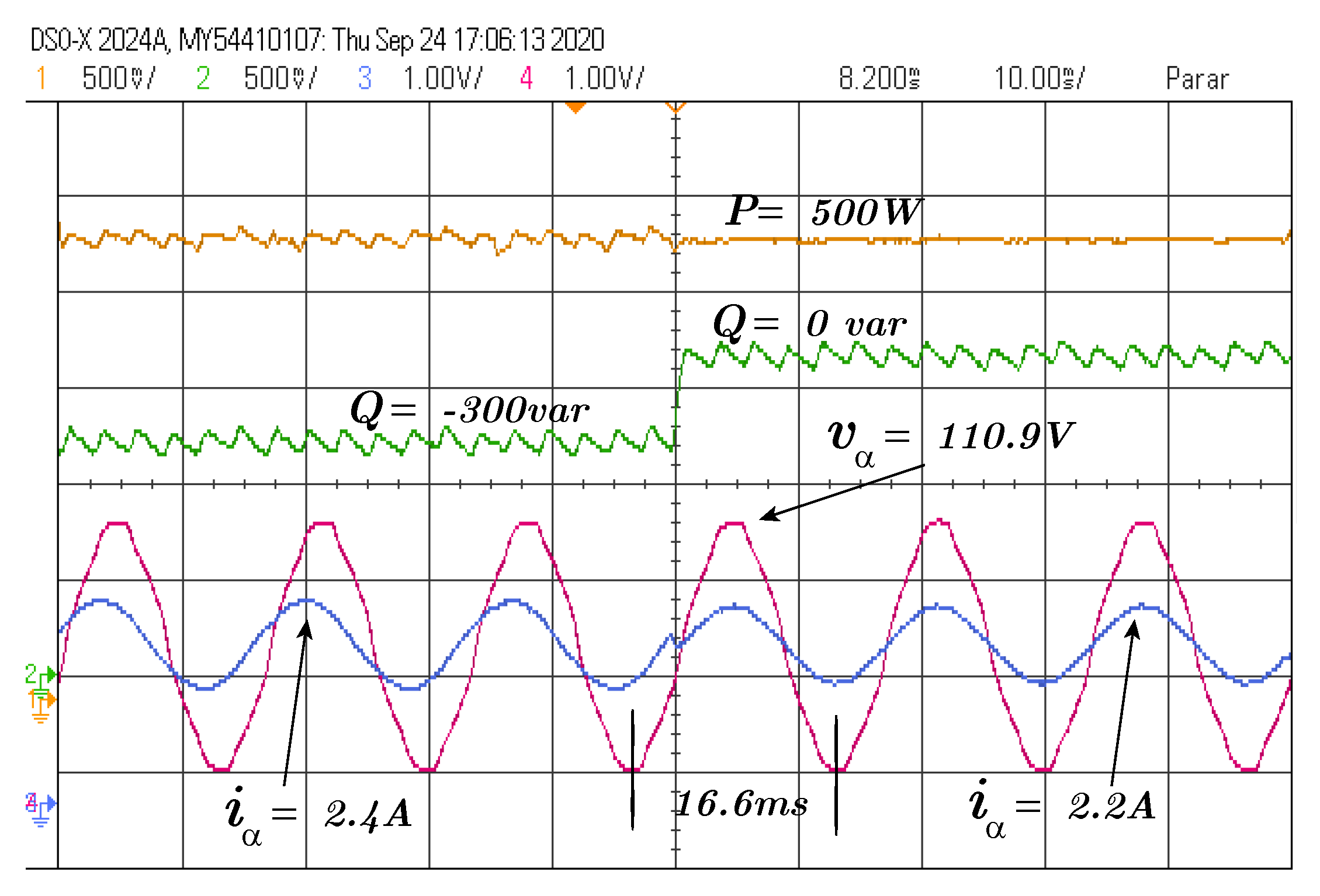
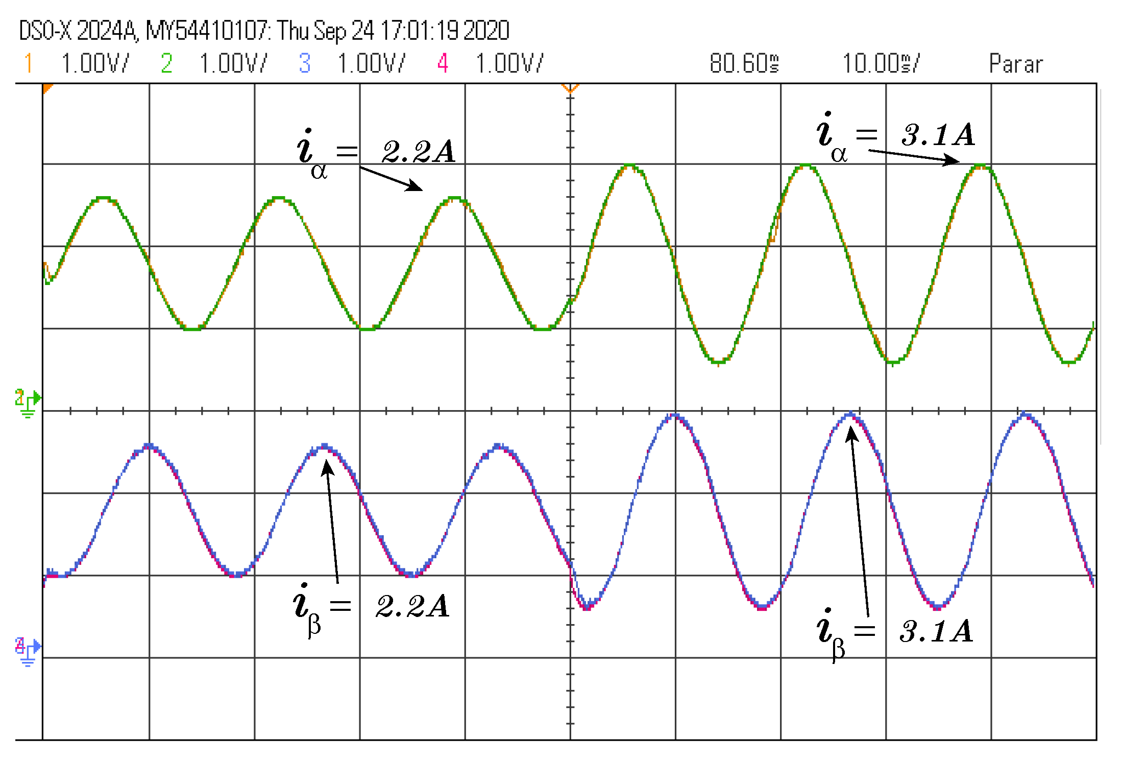
The first test was carried out using a step of reactive power reference from var to 0 var and the active power reference was maintained at 500 W as depicted in Figure 3. The elements of the grid current vector action and the grid voltage and current during this test is depicted in Figure 4 and Figure 5, respectively. It can be seen that the power reach the references and the grid current has no impact due to the harmonics components of the grid voltage. The oscillations in power occurs due to the MPC effort that allows the operation of the grid current as mentioned and due to the distorted voltage. Hence, the MPC allows to reject the disturbance in grid current in this case.
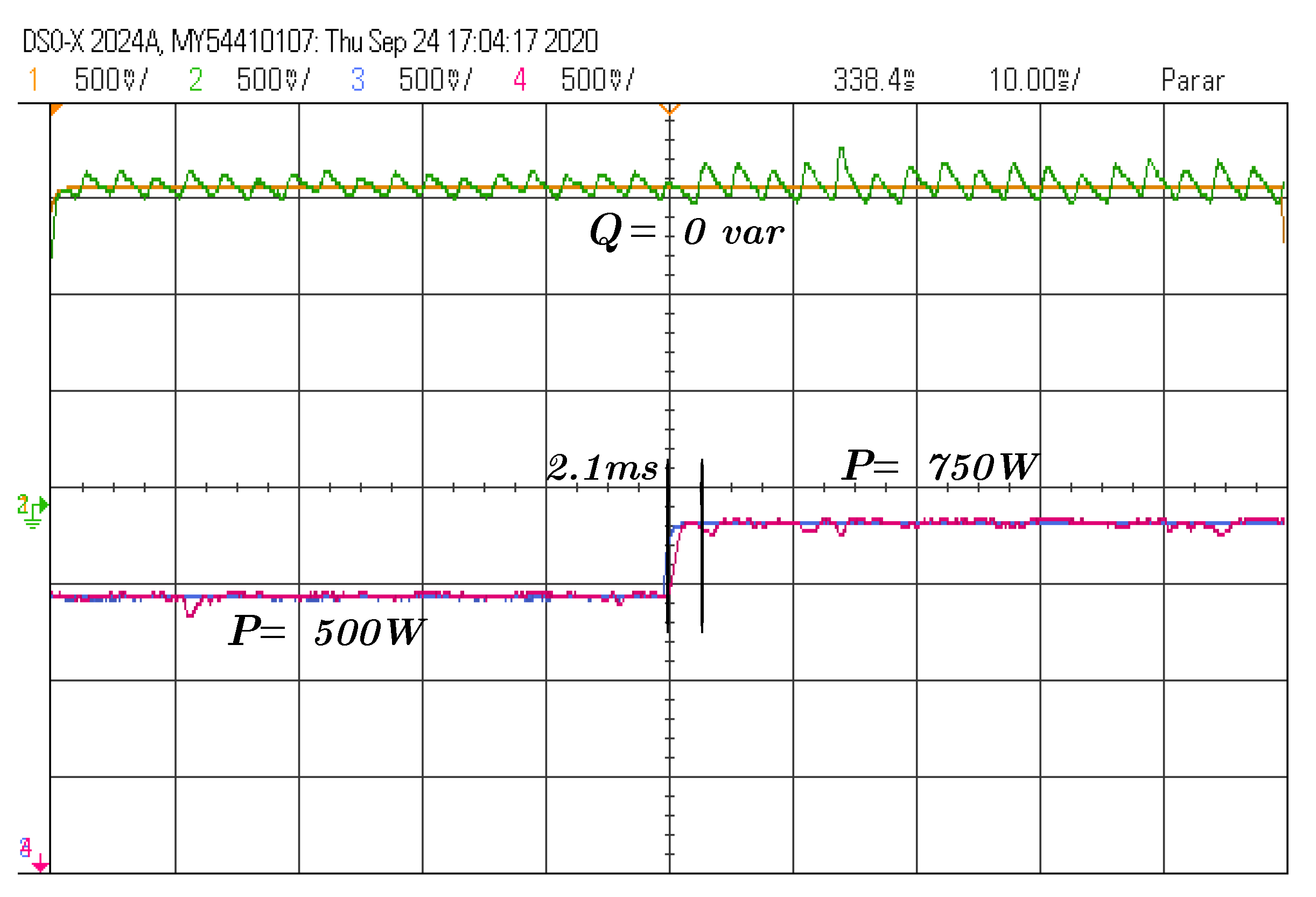
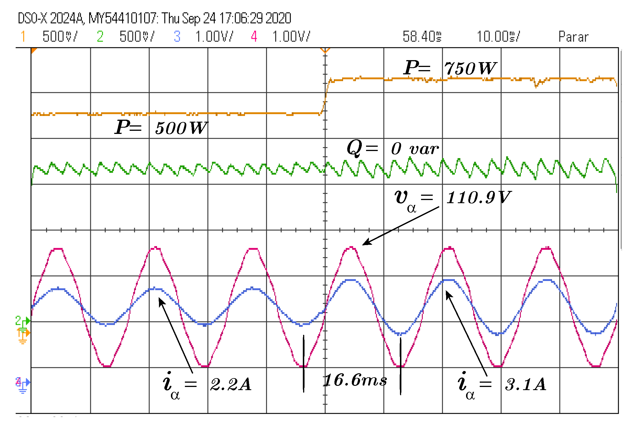
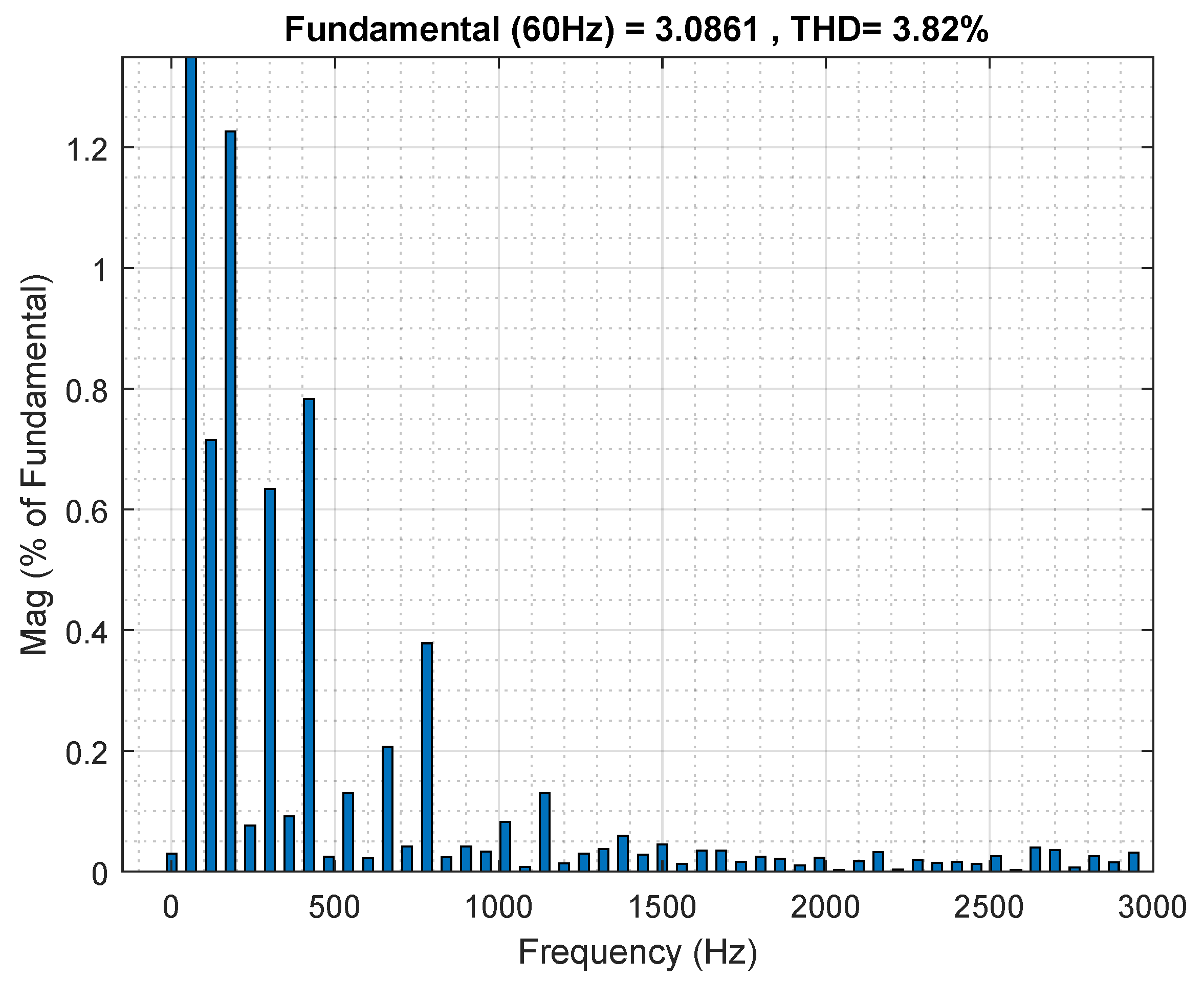
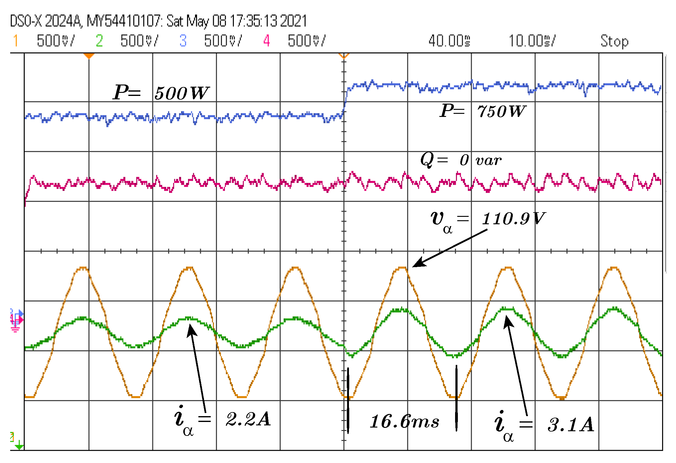
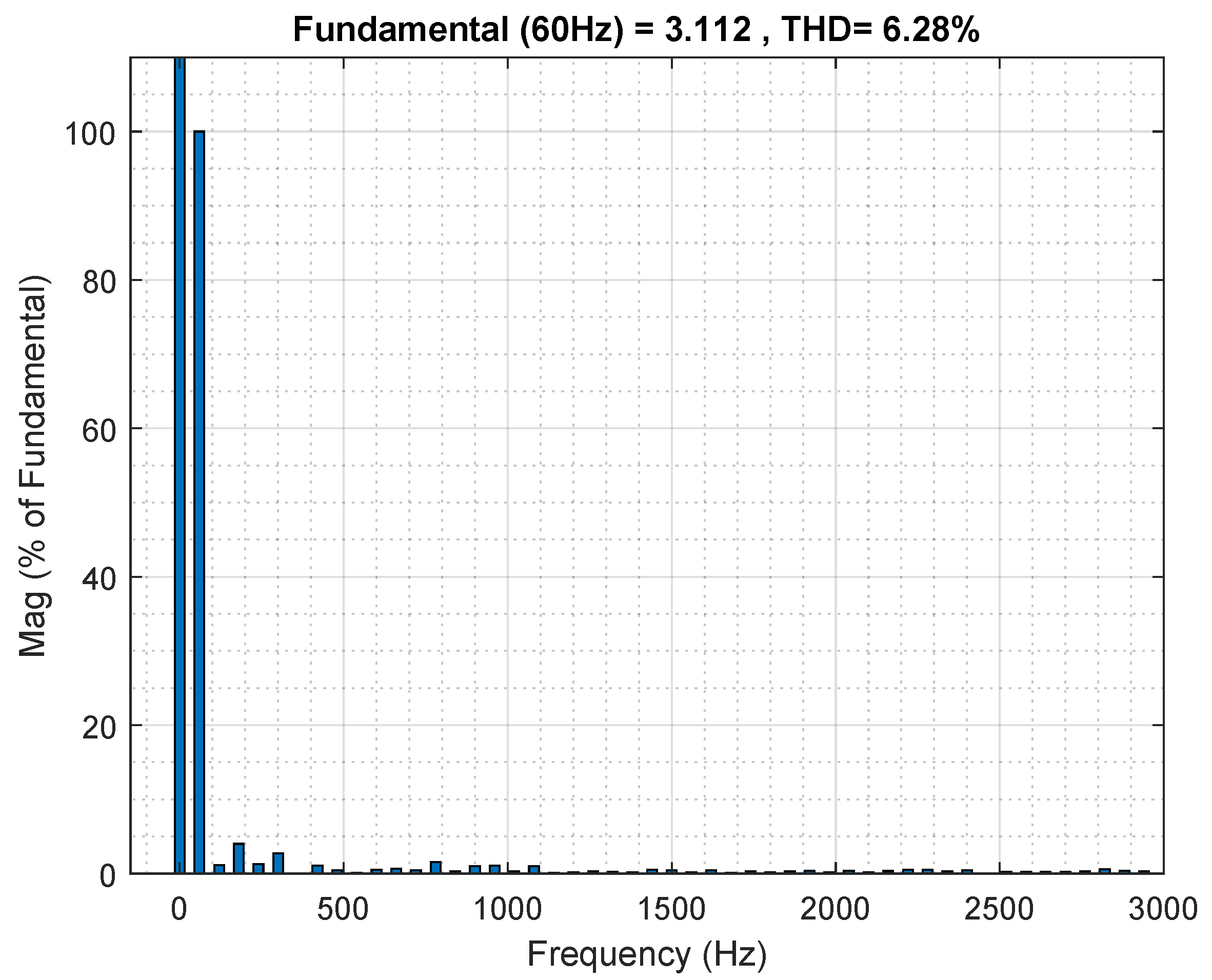
The second test was carried out using a step of active power reference from 500 W to 750 W and the reactive power reference was maintained at 0 var, as depicted in Figure 6. The elements of the grid current vector action and the grid voltage and current during this test is depicted in Figure 7 and Figure 8, respectively, the magnitude values present in the figures are the peak values for voltage and current. The total harmonic distortion (THD) of the grid current is depicted in Figure 9, it is 4.82% and in accordance with the grid requirements of the IEEE Std 1547.2-2008 [23]. It can be seen that the power reaches the references and the grid current has no impact due to the harmonics components of the grid voltage. The oscillations in power occurs due to the MPC effort that allows the operation of the grid current as mentioned and due to the distorted voltage. Hence, the MPC allows the rejection of the disturbance in grid current in this case.
All the details about the signal used to validate the controllers were presented in this section. The most important acquired knowledge during the tests was that the test bench must be a great measure system for current and voltage, it is also necessary a microcontroller solve all the equation because is essential for the controller to generate the correct control signal.
5. Experimental Comparison between FCS and MPC with Modulation
To consolidate the performance of MPC with modulation, a comparison with FCS control [25] is presented in this section using approximated 20 kHz for switching frequency. The proposed evaluation consists in firstly, the peak magnitude of voltage and current signals obtained from the FCS control applied to inverter grid-connected present in Figure 10. This is the same test of the proposal operation depicted in Figure 8.
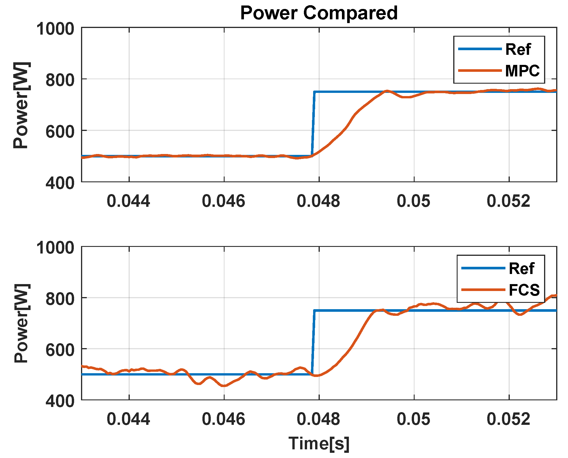
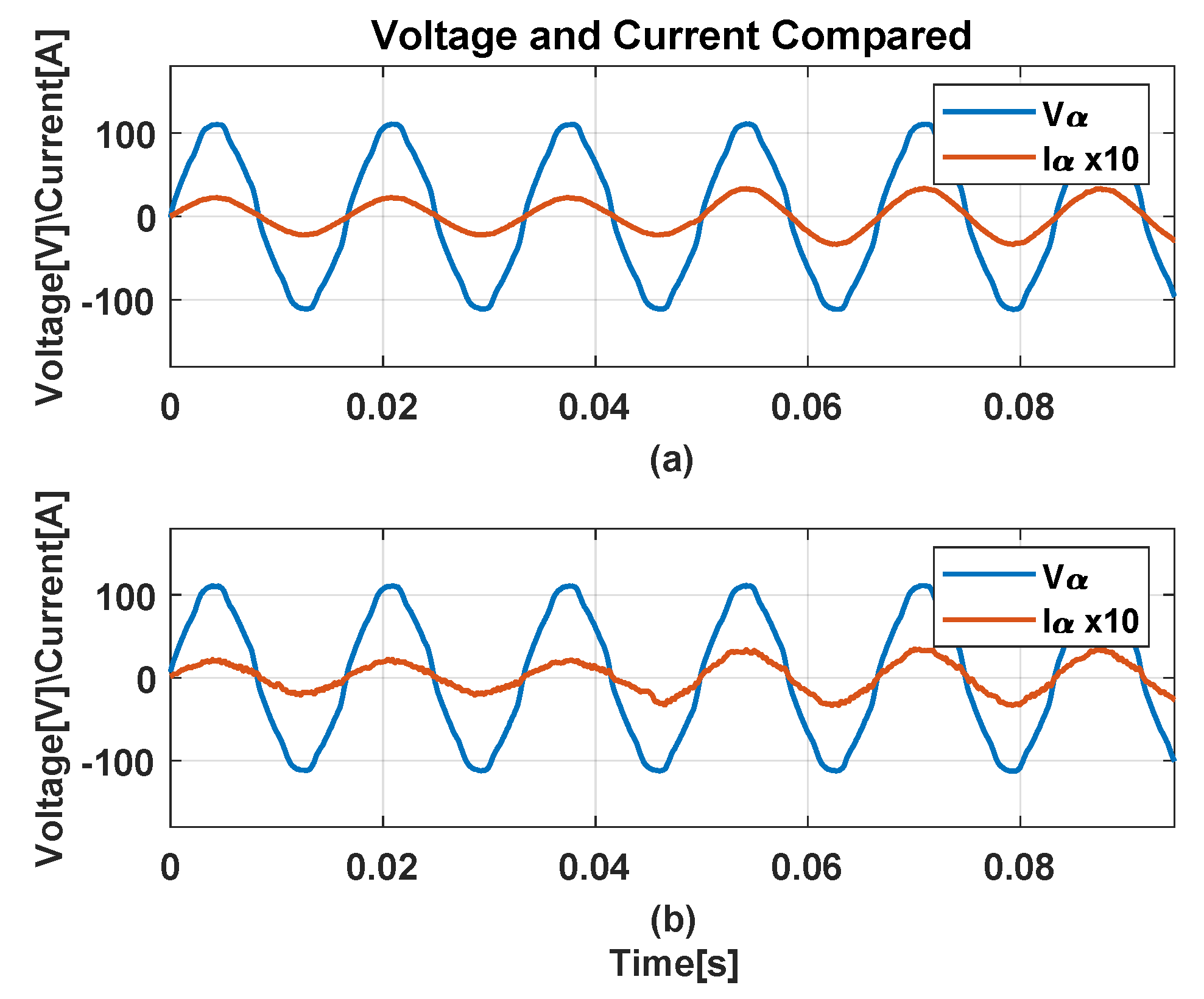
To illustrate the comparison, using the CSV file from the results with MATLAB were created the Figure 11 and Figure 12 using the elements of Figure 10 and Figure 8, respectively.
It is clear that the FCS produces a current with more distortion and the active power has more oscillation if compared to Figure 4, due to the limited number of vector available for FCS [34]. Even both controllers were applied to the three-phase inverter, when the controller proposed in this article chooses which switches will be activated, it can choose more than one voltage vector during the sample period, but the FCS can use only one vector per sample. Due to this, the signals produced by FCS have more oscillation around the references.
The following test presents in Figure 13 the THD for the current generated by the FCS.
The THD of the proposed MPC with modulator operation during distorted voltage depicted in Figure 9 is lower if compared to THD presented in Figure 13, the Table 3 summarize the THD results.
It is proven that the proposed controller is more qualified for renewable energy applications, due to its capability to provide a great quality of current for the grid, even if under voltage distortion.
6. Conclusions
The article presented a proposal for a predictive controller and its practical implementation. The methodology and design process of the controller was presented, which presented a satisfactory result, as an example, a rise time of 2.1 ms for active power and 2.3 ms for reactive power, suitable values when dealing with a power system and with no overshoot, and a low stationary error.
The controller implementation process was presented throughout the article, with the steps for mathematical elaboration applied to the grid-connected inverter system. The proposal is based on the prediction of future values of the system states through the predictive model, in this case, the current in the stationary reference (). The performance of the controller was evaluated in distorted voltage scenarios, which occurs when there is a lot of electronic equipment connected to the electrical network.
The strategy was presented as simple to be implemented in the DSP, as long as the measurement system is correctly calibrated, faithfully representing the voltage values of the currents entered. Furthermore, with the evolution of signal processing systems, it became possible to use a small amount of sampling time, making it easier to measure and act on the system more accurately.
The results show that the MPC technique is a powerful control, which uses a method already consolidated in the literature, but like other controllers, there are numerous ways to be designed, this article presents a new way of application in systems connected to the electrical grid. Finally, it is possible to conclude that the grid current control by the MPC reaches the references of current with little impact due to the harmonics components of the grid voltage and it is in accordance with the grid requirements of the IEEE Std 1547.2-2008 [23]. In future papers to maintain under this subject, the focuses could be related to the robustness of the system under parameters variations. The project of prediction horizons and weights factors according to the performance criteria are the other factors that can be used as focuses for new papers.
Author Contributions
Conceptualization, A.L., E.R.C.D. and A.J.S.F.; methodology, A.L. and A.J.S.F.; software, A.L. and E.R.C.D.; validation, A.L., E.R.C.D., J.d.A., D.A.F. and A.J.S.F.; formal analysis, A.J.S.F.; resources, J.d.A., D.A.F. and A.J.S.F.; data curation, A.L. and E.R.C.D.; writing—original draft preparation, A.L. and E.R.C.D.; writing—review and editing, D.A.F. and A.J.S.F.; visualization, D.A.F.; supervision, A.J.S.F.; project administration, A.J.S.F.; funding acquisition, D.A.F. and A.J.S.F. All authors have read and agreed to the published version of the manuscript.
Funding
This research received external funding by CNPQ and FAPESP.
Institutional Review Board Statement
Not applicable.
Data Availability Statement
Data available in request (A.L. and A.J.S.F.).
Acknowledgments
The authors would like to thank CAPES (Proj. 001) and CNPQ (Process 405757/2018-2) for the financial support.
Conflicts of Interest
The authors declare no conflict of interest.
References
- Bersalli, G.; Menanteau, P.; El-Methni, J. Renewable energy policy effectiveness: A panel data analysis across Europe and Latin America. Renew. Sustain. Energy Rev. 2020, 133, 110351. [Google Scholar] [CrossRef]
- Razavi, S.E.; Rahimi, E.; Javadi, M.S.; Nezhad, A.E.; Lotfi, M.; Shafie-khah, M.; Catalão, J.P. Impact of distributed generation on protection and voltage regulation of distribution systems: A review. Renew. Sustain. Energy Rev. 2019, 105, 157–167. [Google Scholar] [CrossRef]
- Patel, N.; Kumar, A.; Gupta, N.; Ray, S.; Babu, B.C. Optimised PI-4VPI current controller for three-phase grid-integrated photovoltaic inverter under grid voltage distortions. IET Renew. Power Gener. 2020, 14, 779–792. [Google Scholar] [CrossRef]
- Teodorescu, R.; Blaabjerg, F.; Liserre, M.; Loh, P.C. Proportional-resonant controllers and filters for grid-connected voltage-source converters. IEE Proc. Electr. Power Appl. 2006, 153, 750–762. [Google Scholar] [CrossRef] [Green Version]
- Cho, S.; Kang, H.S.; Lee, K.-B.; Yoo, J.Y. Performance Improvement of a Grid-Connected Inverter under Distorted Grid Voltage Using a Harmonic Extractor. Electronics 2019, 1038. [Google Scholar] [CrossRef] [Green Version]
- Li, B.; Yao, W.; Hang, L.; Tolbert, L. Robust proportional resonant regulator for grid-connected voltage source inverter (VSI) using direct pole placement design method. IET Power Electron. 2012, 5, 1367–1373. [Google Scholar] [CrossRef]
- Liserre, M.; Teodorescu, R.; Blaabjerg, F. Multiple harmonics control for three-phase grid converter systems with the use of PI-RES current controller in a rotating frame. IEEE Trans. Power Electron. 2006, 21, 836–841. [Google Scholar] [CrossRef]
- Song, Y.; Nian, H. Stationary frame control strategy for voltage source inverter under unbalanced and distorted grid voltage. In Proceedings of the 2014 IEEE Energy Conversion Congress and Exposition (ECCE), Pittsburgh, PA, USA, 14–18 September 2014; pp. 1167–1173. [Google Scholar]
- Xu, H.; Hu, J.; He, Y. Integrated modeling and enhanced control of DFIG under unbalanced and distorted grid voltage conditions. IEEE Trans. Energy Convers. 2012, 27, 725–736. [Google Scholar] [CrossRef]
- Vazquez, S.; Leon, J.I.; Franquelo, L.G.; Rodriguez, J.; Young, H.A.; Marquez, A.; Zanchetta, P. Model Predictive Control: A Review of Its Applications in Power Electronics. IEEE Ind. Electron. Mag. 2014, 8, 16–31. [Google Scholar] [CrossRef]
- Nguyen, T.; Kim, K.H. Finite Control Set–Model Predictive Control with Modulation to Mitigate Harmonic Component in Output Current for a Grid-Connected Inverter under Distorted Grid Conditions. Energies 2017, 10, 907. [Google Scholar] [CrossRef] [Green Version]
- Calle-Prado, A.; Alepuz, S.; Bordonau, J.; Nicolas-Apruzzese, J.; Cortés, P.; Rodriguez, J. Model predictive current control of grid-connected neutral-point-clamped converters to meet low-voltage ride-through requirements. IEEE Trans. Ind. Electron. 2014, 62, 1503–1514. [Google Scholar] [CrossRef] [Green Version]
- Davari, S.A.; Khaburi, D.A.; Kennel, R. An improved FCS–MPC algorithm for an induction motor with an imposed optimized weighting factor. IEEE Trans. Power Electron. 2011, 27, 1540–1551. [Google Scholar] [CrossRef]
- Rodriguez, J.; Kazmierkowski, M.P.; Espinoza, J.R.; Zanchetta, P.; Abu-Rub, H.; Young, H.A.; Rojas, C.A. State of the art of finite control set model predictive control in power electronics. IEEE Trans. Ind. Inform. 2012, 9, 1003–1016. [Google Scholar] [CrossRef]
- Kim, J.C.; Kwak, S. Model predictive virtual flux control to improve performance under distorted input voltage conditions. IEEE Access 2018, 6, 34921–34933. [Google Scholar] [CrossRef]
- Li, X.; Zhang, C.; Chen, A.; Xing, X.; Zhang, G. Model predictive direct current control strategy for three-level T-type rectifier under unbalanced grid voltage conditions. In Proceedings of the 2018 IEEE Applied Power Electronics Conference and Exposition (APEC), San Antonio, TX, USA, 4–8 March 2018; pp. 1514–1519. [Google Scholar]
- Amiri, M.; Milimonfared, J.; Khaburi, D.A. Predictive Torque Control Implementation for Induction Motors Based on Discrete Space Vector Modulation. IEEE Trans. Ind. Electron. 2018, 65, 6881–6889. [Google Scholar] [CrossRef]
- Sguarezi Filho, A.J.; Filho, E.R. Model-Based Predictive Control Applied to the Doubly-Fed Induction Generator Direct Power Control. IEEE Trans. Sustain. Energy 2012, 3, 398–406. [Google Scholar] [CrossRef]
- Nguyen, H.T.; Jung, J.W. Disturbance-Rejection-Based Model Predictive Control: Flexible-Mode Design With a Modulator for Three-Phase Inverters. IEEE Trans. Ind. Electron. 2018, 65, 2893–2903. [Google Scholar] [CrossRef]
- Barr, M. Pulse width modulation. Embed. Syst. Program. 2001, 14, 103–104. [Google Scholar]
- Conde. D, E.R.; Lunardi, A.; Sguarezi Filho, A.J. Current Control for DFIG Systems Under Distorted Voltage Using Predictive Repetitive Control. IEEE J. Emerg. Sel. Top. Power Electron. 2020. [Google Scholar] [CrossRef]
- Zhang, Y.; Jiao, J.; Liu, J.; Yang, H.; Wan, Q.; Xu, W. Model predictive control of PWM rectifier under unbalanced and distorted network without AC voltage sensor. In Proceedings of the 2019 IEEE Energy Conversion Congress and Exposition (ECCE), Baltimore, MD, USA, 29 September–3 October 2019; pp. 5584–5589. [Google Scholar]
- Photovoltaics, D.G.; Storage, E. IEEE Application Guide for IEEE Std 1547TM, IEEE Interconnecting Distributed Resources with Electric Power Systems; IEEE: Piscataway, NJ, USA, 2009; pp. 1–217. [Google Scholar] [CrossRef]
- Alepuz, S.; Busquets-Monge, S.; Bordonau, J.; Cortes, P.; Rodriguez, J.; Vargas, R. Predictive current control of grid-connected neutral-point-clamped converters to meet low voltage ride-through requirements. In Proceedings of the 2008 IEEE Power Electronics Specialists Conference, Rhodes, Greece, 15–19 June 2008; pp. 2423–2428. [Google Scholar]
- Rodriguez, J.; Cortes, P. Predictive Control of Power Converters and Electrical Drives; John Wiley & Sons: Hoboken, NJ, USA, 2012; Volume 40. [Google Scholar]
- Beres, R.N.; Wang, X.; Liserre, M.; Blaabjerg, F.; Bak, C.L. A review of passive power filters for three-phase grid-connected voltage-source converters. IEEE J. Emerg. Sel. Top. Power Electron. 2015, 4, 54–69. [Google Scholar] [CrossRef] [Green Version]
- Rodrigues, L.L.; Vilcanqui, O.A.C.; Murari, A.L.L.F.; Filho, A.J.S. Predictive Power Control for DFIG: A FARE-Based Weighting Matrices Approach. IEEE J. Emerg. Sel. Top. Power Electron. 2019, 7, 967–975. [Google Scholar] [CrossRef]
- Kennel, R.M.; Kazmierkowski, M.; Rodriguez, J.; Cortes, P. Predictive control in power electronics and drives. In Proceedings of the 2008 IEEE International Symposium on Industrial Electronics, Cambridge, UK, 30 June–2 July 2008; pp. 1–90. [Google Scholar]
- Akagi, H.; Kanazawa, Y.; Nabae, A. Instantaneous Reactive Power Compensators Comprising Switching Devices without Energy Storage Components. IEEE Trans. Ind. Appl. 1984, IA-20, 625–630. [Google Scholar] [CrossRef]
- Rossiter, J.A. Model-Based Predictive Control: A Practical Approach; CRC Press: Boca Raton, FL, USA, 2003. [Google Scholar]
- Silva, L.H.; Sguarezi Filho, A.J.; Fernandes, D.A.; Costa, F.F.; Cardoso, A.J.M. A robust phase-locked loop against fundamental frequency deviations and harmonic distortions. Electr. Power Syst. Res. 2018, 163, 338–347. [Google Scholar] [CrossRef]
- Rodriguez, P.; Pou, J.; Bergas, J.; Candela, J.I.; Burgos, R.P.; Boroyevich, D. Decoupled Double Synchronous Reference Frame PLL for Power Converters Control. IEEE Trans. Power Electron. 2007, 22, 584–592. [Google Scholar] [CrossRef]
- Pang, B.; Nian, H.; Wu, C.; Cheng, P. Stator Harmonic Current Suppression for DFIG System Considering Integer Harmonics and Interharmonics. IEEE Trans. Ind. Electron. 2018, 66, 7001–7011. [Google Scholar] [CrossRef]
- Rodriguez, J.; Pontt, J.; Silva, C.A.; Correa, P.; Lezana, P.; Cortés, P.; Ammann, U. Predictive current control of a voltage source inverter. IEEE Trans. Ind. Electron. 2007, 54, 495–503. [Google Scholar] [CrossRef]
Figure 1.
Grid current control using MPC with modulator.

Figure 2.
Experimental bank setup.

Figure 3.
Reactive power step test using MPC under distorted grid voltage. Yellow and blue line are the references.
Figure 3.
Reactive power step test using MPC under distorted grid voltage. Yellow and blue line are the references.

Figure 4.
Grid current behavior during reactive power step test using MPC under distorted grid voltage. Yellow and blue line are the references.
Figure 4.
Grid current behavior during reactive power step test using MPC under distorted grid voltage. Yellow and blue line are the references.

Figure 5.
Grid current and Voltage behavior during reactive power step test using MPC under under distorted grid voltage.
Figure 5.
Grid current and Voltage behavior during reactive power step test using MPC under under distorted grid voltage.

Figure 6.
Active power step test using MPC under distorted grid voltage. Yellow and blue line are the references.
Figure 6.
Active power step test using MPC under distorted grid voltage. Yellow and blue line are the references.

Figure 7.
Grid current behavior during active power step test using MPC under distorted grid voltage. Yellow and blue line are the references.
Figure 7.
Grid current behavior during active power step test using MPC under distorted grid voltage. Yellow and blue line are the references.

Figure 8.
Grid current and voltage behavior during active power step test using the proposed MPC under distorted grid voltage.
Figure 8.
Grid current and voltage behavior during active power step test using the proposed MPC under distorted grid voltage.

Figure 9.
THD of the grid current using MPC under distorted grid voltage.

Figure 10.
Grid current and voltage behavior during active power step test using FCS under distorted grid voltage.
Figure 10.
Grid current and voltage behavior during active power step test using FCS under distorted grid voltage.

Figure 11.
Power compared between MPC and FCS in the active power step.

Figure 12.
Voltage and current compared between MPC and FCS in the active power step.

Figure 13.
THD of the grid current using FCS under distorted grid voltage.


Table 1.
Three phase power inverter parameters.
| Parameter | Value |
|---|---|
| Inductor internal resistance per phase () | |
| Inductance per phase () | 22 mH |
| Nominal Grid Frequency | 60 Hz |
| Nominal Grid Voltage () | 78 V |
| Sampling Frequency | 20 kHz |
| Switching Frequency () | 20 kHz |
| 3 | |
| 2 | |
Table 2.
Harmonic distortion values.
| Harmonic Components | 5th | 7th | 11th | 13th | 17th | 19th |
|---|---|---|---|---|---|---|
| Percentage of Fundamental |
Table 3.
Harmonic Distortion Values.
| Controller | MPC | FCS |
|---|---|---|
| TDH [%] |
Publisher’s Note: MDPI stays neutral with regard to jurisdictional claims in published maps and institutional affiliations. |
© 2021 by the authors. Licensee MDPI, Basel, Switzerland. This article is an open access article distributed under the terms and conditions of the Creative Commons Attribution (CC BY) license (https://creativecommons.org/licenses/by/4.0/).
Share and Cite
MDPI and ACS Style
Lunardi, A.; Conde D, E.R.; de Assis, J.; Fernandes, D.A.; Sguarezi Filho, A.J. Model Predictive Control with Modulator Applied to Grid Inverter under Voltage Distorted. Energies 2021, 14, 4953. https://doi.org/10.3390/en14164953
AMA Style
Lunardi A, Conde D ER, de Assis J, Fernandes DA, Sguarezi Filho AJ. Model Predictive Control with Modulator Applied to Grid Inverter under Voltage Distorted. Energies. 2021; 14(16):4953. https://doi.org/10.3390/en14164953
Chicago/Turabian StyleLunardi, Angelo, Eliomar R. Conde D, Jefferson de Assis, Darlan A. Fernandes, and Alfeu J. Sguarezi Filho. 2021. "Model Predictive Control with Modulator Applied to Grid Inverter under Voltage Distorted" Energies 14, no. 16: 4953. https://doi.org/10.3390/en14164953
Note that from the first issue of 2016, this journal uses article numbers instead of page numbers. See further details here.