
Decentralized Voltage Control in Active Distribution Systems: Features and Open Issues


1
Department of Electrical and Information Engineering, Università degli Studi di Cassino e del Lazio Meridionale, 03043 Cassino, Italy
2
Engineering Department, University Niccolò Cusano, 00166 Roma, Italy
*
Author to whom correspondence should be addressed.
†
These authors contributed equally to this work.
Energies 2021, 14(9), 2563; https://doi.org/10.3390/en14092563
Submission received: 29 March 2021
/
Revised: 23 April 2021
/
Accepted: 27 April 2021
/
Published: 29 April 2021
(This article belongs to the Special Issue Smart Grid Voltage Control)
Abstract
:Voltage control is becoming a key issue in active distribution systems, which are electric distribution networks characterized by a large penetration of DERs. Traditional voltage control devices, as well as the active and reactive powers injected by DERs, can be used as ancillary services to support voltage profiles along the distribution feeders. Due to the peculiar characteristics of active distribution systems, the decentralized control approach presents the most promising technical and economical features. In the paper, the decentralized voltage control structure is hierarchically decomposed into different control levels, characterized by different objectives and time frames. The primary and secondary control levels have been analyzed, always according to a decentralized approach. For each level, the various techniques for solving the voltage control problem that have been proposed in the literature are presented, and their main features compared. The main open issues related to the real time practical implementation of the decentralized architectures at both primary and secondary voltage control levels are investigated, keeping always in mind both technical and economical aspects, which always represent the components of a trade-off solution.
1. Introduction
The integration of Distributed Energy Resourses (DERs) in electric power systems has rapidly increased in the last decade, transforming distribution systems from passive to active, and severely impacting on their operation, protection, and control [1,2]. In fact, DERs are often connected close to or at customers’ premises, and consequently have a significant effect on the technology, the economy, and the environmental impact of the distribution network (DN), as well as of the customers [3,4,5]. Several challenges arise that can be categorized as technical, commercial, and regulatory. This paper deals only with the technical ones.
To connect DERs while keeping a stable and correct operation of the distribution system, it is fundamental to analyze the interaction between DERs and the distribution system [6]. The traditional architecture of the DN was conceived to provide the electric power from the feeding substations to the loads according to a unidirectional flow. The DERs supply the nearby loads but, in case the DER injections exceed the customers’ demand, the surplus power flows in the opposite direction, toward the higher voltage systems. In this sense, it can be stated that the distribution system evolves towards a bidirectional network with several undesirable effects on its operation and protection [7,8]. Some of the drawbacks are mainly related to the variations of the voltage profiles along the feeders, the voltage harmonic distortion, and the changes of the fault currents in both amplitudes and directions [9] with the consequent malfunction of the protection systems [10]. Several studies were conducted to review and solve the stability problems, the functioning, and control methodologies to apply to power systems when large amounts of DERs are connected. Some of them focused in Micro Grid (MG) structures [11,12], others considered power quality issues [13,14], and others discussed control devices and methodologies involving reactive power and voltage management [15,16].
Among the various technical issues, this paper focuses on the voltage control problem in active distribution systems, meant as distribution systems with a large penetration of DERs. In fact, the voltage regulation is one of the main issues that can limit the spreading of DERs in the DN and requires improved strategies with respect to the past [6,8]. Many studies on this matter tried to implement methods to quantify the maximum amount of DERs to connect to a particular network according to the characteristics of the feeder where the connections take place, the amount of customers’ demand, and the kind of DN [17]. However, the progress in the fields of control systems and communication technologies allows us to turn the problem of DER connection into an opportunity. Differently from the former approach aiming at containing the negative impact of DERs, the new paradigm is to exploit DERs as sources of flexibility services that contribute to voltage control and, more generally, support correct operation of the distribution system. To this aim, the adoption of innovative control systems is mandatory. The expected result is that DERs will bring, both to the distribution systems and to the customers, greater benefits than their installation costs.
The challenge of converting DERs from problems to be faced into service providers that support the DN operation by exploiting their flexibility is still far from being won in real systems. The barriers are regulatory, economical, and technical. Concerning the technical issues that are the focus of the paper, practical implementations have mainly concerned microgrids, in which the number of DERs and actors as well as the network extension are limited and, consequently, problems related to many issues are not significant (data exchange among DERs, communication systems, data reliability and coherency, and coordination of various actors with different conflicting objectives). On the other hand, in active DN, the first industrial applications of flexible DER control to support the system operation have mainly concerned the MV DNs, which already present a basic level of automation, including often a supervisory control system at HV/MV substation level that acquires data from all the network. In LV distribution systems, the automation level is quite low and often limited to few functions at MV/LV substation level without direct real-time data collection from the network. In these systems, the practical implementations of automatic smart grid functions for DERs are still at their beginning [18].
The first flexible voltage control schemes for active DNs are beginning to be implemented according to a centralized control architecture, concentrating data and intelligence at substation level. Indeed, real-time control is better achieved by efficient control schemes that can distribute the tasks among multiple controllers, each one solving a smaller subpart of the problem and re-solving it frequently, as it is actually needed [19]. The advantages of such architectures are several, as detailed later in Section 2.2, because they fully exploit the constant innovative developments of ICTs. These architectures are classified in various ways. A classification based on the communication network according to [19] distinguishes the following types: i. local control without communication, ii. centralized control, iii. distributed control, and iv. decentralized control in zones. In the reminder a different classification based on the control approach according to [20] is adopted, which distinguishes between centralized and decentralized control architectures, and among the latter ones, between decentralized autonomous and decentralized coordinated control.
In the above frame, the paper focuses on the technical challenges to be faced adopting decentralized (autonomous or coordinated) architectures for the voltage control problem in active DN. Its main contribution is to present the methodologies and the steps required to design and implement voltage control with a decentralized architecture. While progressing in the description of the steps, the main techniques proposed in the literature are recalled, aiming at classifying them and presenting their advantages and disadvantages, rather than giving the reader a complete review of the literature in this field. For this reason, the paper is structured as follows. In Section 2, the voltage control problem in active DN is first defined in terms of objectives and means and of possible control architectures, and then decomposed into hierarchical levels. In Section 3, the decentralized primary control level is analyzed, presenting the main issues related to system modeling and control design; in Section 4 the secondary control level is treated, focusing in particular on the most promising approach, that is the decentralized coordinated architecture based on voltage control zones. For both the control levels the numerical results of a case study are also presented to give evidence of the practical viability of the methodologies. Finally, in Section 5 the open issues and the future challenges to be faced in decentralized voltage control of active DNs by means of DERs are discussed. Abbreviations and the main symbols used throughout the paper are listed at the end of the paper.
2. The Voltage Control Problem
2.1. Objectives and Means for Voltage Control
In traditional distribution systems the voltage control problem has been tackled with a different approach from the one adopted for the transmission systems. In fact, the peculiar characteristics of the distribution systems are the following [21]: i. the operation in radial topology, ii. the presence of significant unbalances, and iii. the higher line R/X ratios than the ones of the transmission network. These features have two major consequences: i. the voltage drop is higher for the distribution feeders with respect to transmission lines and can differ among the three phases; ii. the real power flows have a comparable or even larger influence on the voltage profile with respect to the reactive power flows [22]. Moreover, distribution systems present a large number of nodes and customers and a low grade of automation. Consequently, in distribution systems, the primary objective of the voltage control is usually restricted to maintaining the voltage amplitudes within the regulatory limits in all the nodes, in spite of the changes of the operating and loading conditions.
The voltage control is usually performed by means of some specific voltage control devices, namely on load tap changers (OLTCs), switched capacitors (SCs), step voltage regulators (SVRs) [20], and reactive power compensating devices. Conventional OLTCs and SCs usually present a slow response to voltage variations [12,23]. Currently, over traditional mechanical OLTCs, new solid state OLTCs are performing better with lesser maintenance cost. They provide significant control capability such as coordinated control with communication [24]. SVR is also a tap changing automatic voltage regulator, but it is located along the feeder [25]. Reactive power compensating devices are either synchronous generators or static VAR systems (SVSs), these latter ones being the cheaper solution. SVSs react faster than conventional SVRs and OLTCs [26,27].
In active distribution systems, new additional means to control voltages are available:
- Generation curtailment during low demand: voltage along the distribution feeder is limited by reducing the injection of active power; however, if the electric power is generated from renewable energy sources, this method causes a reduced exploitation of the available source and, then, is neither efficient nor environmentally desirable;
- Energy storage: by controlling the charging and discharging of the distributed Energy Storage system (ESS), the voltage fluctuation along the DN can be reduced;
- Power electronic converters at DER sites: the converters that interface DERs to the network can be used to control the active and reactive power absorption/injection so as to regulate the voltage;
- Load management: shifting or curtailing/increasing the energy demand by customers can help to support the voltage.
In a general sense, these means can be viewed as flexibility services provided by DERs to the distribution system; such services favor the matching between the variable energy demand and the increasingly-variable energy supply. By exploiting the flexibility offered by DERs, the voltage control can aim at new objectives, beyond the simple assurance of the respect of the voltage limits, so as to improve the efficiency and reliability of distribution system operation. In particular, the voltage control can impose voltage profiles that are optimal with respect to various objective functions proposed in the literature, such as:
- minimizing the total reactive power exchange;
- optimizing, from the economical point of view, the reactive power exchange with the transmission network through the substation;
- minimizing the active power curtailment for renewable energy generators;
- minimizing active power losses of the distribution system;
- maximizing the DER active power output;
- minimizing the voltage deviations from their rated values.
These objectives concern the overall distribution system operation and can be pursued by the voltage control system that acts on the DERs and the other voltage control devices connected at various nodes of the DN. Then, a key issue arises concerning the choice of the architecture of the voltage control system. The first point is whether the control system uses a communication network. The constant developments in the telecommunications field warrant considering only communication-based architectures. Among these latter ones, two main categories can be distinguished, namely centralized and decentralized architectures; their main features are summarized in the next Section 2.2.
2.2. Centralized and Decentralized Control Architectures
The centralized control architectures are based on a single central control center (C.C.) that receives all the required measurements from the grid, possibly through smart meters and/or remote terminal units, retrieves the solution to the voltage control problem, and communicates the set-points to the DERs and to the other voltage control devices [19]. The C.C. is the only network component that can initiate a control action. The main feature of the centralized control architecture is that the management and control is obtained by optimally dispatching DERs to satisfy specific objectives that account for the overall distribution system. This is mainly attained by techniques that solve non-linear programming problems based on short term load and generation forecasts [28].
However, the main drawback of the centralized architecture lies in the necessity of handling a big amount of data. Moreover, the application of centralized control requires investments for costly communication channels to guarantee network observability and promptness of the control action. Further negative consequences are related to the vulnerability of the control system to cyber-attacks and communication failures. Then, it can be stated that the smaller the network is, the more viable the centralized architectures are, such as in the case of microgrids, so that investment in communication infrastructures and sensor devices is limited. In active DNs with a large penetration of DERs, further difficulties may arise adopting the centralized architecture. In particular, both the uncertainties and the dimension of the numerical problems to be tackled by the control system increase, due to the presence of intermittent renewable sources, electric vehicles, storage systems, dynamic loads, reconfiguration. Moreover, the centralized architecture typically lacks of flexibility and scalability, making it difficult to adopt the plug-and-play approach, in which DERs can be connected/disconnected to/from the DN without significant changes in the system operation and control.
An alternative is represented by decentralized architectures which mainly rely on local measurements and simple calculations, and thus significantly reduce the requirements of communications. The decentralize architectures result to be flexible, scalable, reliable, and resilient. In fact, decentralized controllers are quite autonomous, receiving local measurements and information, processing them, and providing counteractions to achieve the appropriate control.
Decentralized architectures may also be based on zone controllers rather than on single DER controllers. In fact, the voltage profile of an area is mainly affected by the powers injected by the DERs of the same area. This characteristic proves that the optimization and the voltage control are much better to be zonally accomplished [29]. In this sense, the proposed methodologies concentrate on dividing the DNs into different smart grid areas (SGAs) which are considered as one of the viable solutions for future power systems [30,31]. A SGA can be defined as part of the DN that constitutes a self-sufficient system, enabling the integration of any type of DER to the grid, that can offer safe, reliable, high-quality, and sustainable electricity to consumers and organizations alike. In the remainder, reference is made to the Voltage Control Zones (VCZs), which represent a reduction of the more general concept of SGAs to the peculiar problem of voltage control and which are detailed in Section 4.3.
However, two main issues arise in the decentralized approach. The first one is that the optimal operation of the overall distribution system may not be guaranteed. The second one is that the simultaneous response of local controllers may cause operational conflicts, negative interactions, and system instability. Information exchange among the autonomous controllers can help to tackle these two issues by introducing a coordinating action in the decentralized architectures. In fact, sharing local information (individual states and control actions) allows the local controllers to coordinate one with the other to overcome the stability problems and to achieve the global optimal operation. The performance of the decentralized architecture can be further improved by arranging various layers/time scales. In fact, the overall voltage control problem can be formulated on different levels with different time horizons, namely with respect to the local controllers and their interactions and with respect to the optimal operation of the overall distribution system. Such hierarchical decomposition of the voltage control problem is introduced in the next Section 2.3.
2.3. Hierarchical Decomposition
The hierarchical decomposition identifies different control levels, assigning specific objectives and time frames to each level. Typically, up to three layers are identified, named primary, secondary, and tertiary control levels [32,33,34,35].
The primary control layer aims at controlling voltage at some specific nodes. It is typically implemented in a decentralized architecture: each DER is equipped with a local control that acquires measurements of the DER quantities and of the node of the distribution system at which the DER is connected and acts on the DER to impose the voltage and other electrical quantities, such as injected powers, at the connection node. Concerning the time frame, it is a real time control, typically implemented with classical closed-loop controllers.
The local control is made possible thanks to the use of power electronic converters interfacing DERs with the grid. The converter configuration is typically a voltage source converter (VSC) operating in current control mode (CCM) [36]. In these cases, the local control is implemented with multiple control loops, distinguishing the inner control loops which rapidly act as current control and the outer control loops that regulate voltage and/or exchange powers with the grid [37], as shown in Figure 1.
The inner control involves reference frame extraction and current closed-loop control. To extract the reference frame, the most widely adopted methodology is the synchronous reference frame theory based on the Park’s transforms and the axis frame [38]. The reference frame is extracted by a Phase-Locked Loop (PLL) and coherent with the network voltage. Concerning the current control loops, they are well-studied in the literature, and various solutions have been proposed. Indeed, classical PI regulators often provide adequate performance, see among them [39,40,41,42], and are preferred because of their well-established tuning techniques. For this reason, no remarkable issues are to be discussed for the inner control loop.
The outer control regulates some electrical quantities at the node of the distribution grid. In particular, it regulates the injected active power and either the injected reactive power or the voltage amplitude. Furthermore, the outer control is local, acquiring the measurements at the point of common coupling (PCC) and generating as outputs the current set-points for the inner control. The time response of the outer control loops is of a few seconds, which is an order of magnitude larger than the time response of the inner control loops, so as to avoid dynamic coupling among the two controls.
The decentralized architecture based on local control is always adopted because a centralized approach would be hard to be implemented in the real time frame due to the presence of many DERs dispersed in the network. However, such an architecture presents a main drawback: interactions among the local controllers of different DERs or devices are possible, in particular when voltage is regulated. In fact, the variation of the current injected by a DER causes variations of the voltages at all the nodes of the distribution grid and also of the voltages regulated by other DERs. The issue of coping with such interactions is discussed in the next Section 3, referring in particular to the case of voltage regulation.
The secondary control can have various objectives, such as eliminate the voltage deviations [43,44], improve reactive power sharing, reduce distribution losses, and harmonic elimination. At the secondary control level, economical issues are also involved: in particular, the cost of the flexibility services offered by DER can impact on the sharing among DERs, especially when active power flexibility is involved. The optimization targets are achieved by monitoring the operating status of the distribution system, determining the actions to be implemented, and sending the evaluated set-points to the primary control level, that are active powers to be injected/absorbed and voltage amplitudes to be imposed. The time-frame of the optimization is from a quarter of an hour up to an hour. The secondary control can be implemented according to a centralized or a decentralized architecture, this latter one being organized in VCZs. The decentralized approach for the secondary voltage control is treated in Section 4.
Finally, the tertiary control level is usually implemented by a centralized controller to pursue economical objectives in operational planning of the distribution system with a time-frame of hours. In the future this level should evolve toward liberalized architecture, with the creation of service markets in which DERs offer flexibility services (either directly or through aggregators) to the Distribution System Operator (DSO). The tertiary level is out of the scope of this paper.
3. Decentralized Primary Voltage Control
In the past, a primary voltage control level was not implemented in LV DNs, but the regulating action was limited to an appropriate choice for the off-load tap position of the MV/LV transformers in the secondary substations. Concerning MV DNs the primary voltage control level was basically achieved by a voltage regulator acting on the on-load tap changer of the HV/MV transformers of the primary substation; some additional voltage regulating devices were installed along the feeders in the case of particular needs. On the other hand, the introduction of distributed generation (DG) has had a negative impact on the nodal voltage profiles along the feeders, often causing overvoltages. To counteract this phenomenon, initially an “on/off control action” was adopted, that trips off the DG when the voltage at the PCC overcomes some fixed thresholds [45].
Since the last two decades the distribution systems are gradually evolving toward the concept of smart grids of the future by installing smarter primary/secondary substations and exploiting DG and other DERs to guarantee adequate grid operation [46]. Then, the primary voltage control level requires to act on a large number of devices connected at various nodes of the DNs. In this view, the relative simplicity and low cost of the decentralized local approaches make them attractive with respect to complex centralized schemes that require large investments [19]. Since the reactive power is the first resource to be used for voltage support and over-voltage containment, international standards have been revised to ask DERs for adequate reactive power capabilities so as to support the DSO in voltage regulation [47,48]. To this aim, DERs must be equipped with a reactive power control loop that can regulate the voltage at the bus where they are connected.
However, since the DNs, in particular the LV ones, are usually characterized by high ratios, the control of the only reactive power may not guarantee adequate voltage regulation. Then, in the literature active power curtailment techniques have been proposed to improve voltage containment [28,49,50,51]. However, in the decentralized approach, a drawback is the non-uniform active power curtailment [28] and the risk of cascading in LV single-phase DERs [45]. Moreover, active power curtailment has negative impacts on the generation economic revenues and on the environment, reducing the exploitation of renewable energy sources. The most recent trend is to include voltage regulation in the set of ancillary services at the distribution system level. A recent EU directive [52] indicates that the DSO shall procure the non-frequency ancillary services needed for its system in accordance with transparent, non-discriminatory and market-based procedures. In practice, to allow more DERs, the modulation of active power for voltage control will be either mandatory or economically rewarded. In this frame, a flexible power regulation that acts on both reactive and active powers of DERs to provide ancillary services is proposed in [53], but in the case of only one PV system with ESSs. Always referring to PV systems with ESSs, Ref. [54] proposes to act on both active and reactive powers to smooth the impact on DN and to monitor the voltage at the PCC. However, the control is based on a heuristic iterative procedure. In conclusion, the present and future research must investigate decentralized control schemes acting on both reactive and active powers of the DERs to provide the ancillary service of voltage regulation at the PCCs.
As introduced in Section 2.2, in the decentralized approach, a problem may arise due to the simultaneous responses of the local controllers which interact through the network, thus causing operational conflicts, negative interactions, and even system instability [55,56,57,58]. To correctly cope with this problem adequate design of the local controllers is performed by the following two steps.
Firstly, an adequate model of the distribution system with DERs must be built so as to correctly account for the interaction among the local controllers. To this aim, in the following Section 3.1 adequate Multiple Input Multiple Output (MIMO) modeling is discussed.
Secondly, an adequate coordination among the local controllers must be assured. Coordination can be performed either online, by adequate chains of command, typically based on multi-agent techniques [59,60], or offline at the design stage [61,62]. In the former approach, the requirements in terms of real-time data exchange among the local controllers are significant thus making online coordination impracticable for a large number of DERs. Alternatively, offline coordination can be implemented at the design stage with the significant advantage of avoiding any real-time communication among the local controllers. Then, such a coordination is preferable for the primary voltage control level and discussed in Section 3.2.
3.1. System Model
To design the local voltage controllers, it is necessary to adopt adequate MIMO models that represent the distribution system with DERs, including the coupling among the controllers through the DN.
DER modeling has widely been treated in the literature, considering two categories of DERs. The first category includes rotating machines which are directly connected to the network; for them, well known models are available. As recalled in Section 2.3, research has focused on electronically-interfaced DERs, which typically include a VSC in CCM and a three phase filter. The aim is to derive the transfer functions that relate the active and reactive powers injected/absorbed by a DER to the current reference signals sent to the VSC. Current signals are decomposed along the axis of a reference frame, which jointly rotates with the voltage of the point of connection to the DN. Such a frame is obtained by a PLL which allows to assume that the d and q current components independently control, respectively, active and reactive powers [63]. Indeed, since the time response of the PLL is short but not null, and due to the presence of the filter, the two current components are not fully independent and more accurate modeling should be developed to account for the coupling. The general form of the kth DER model in the Laplace domain is:
where and are the active and reactive powers injected/absorbed by the DER; and are the current reference components along the d and q axis; is a matrix of transfer functions whose expression is given by
The diagonal transfer functions model the dynamics along the d and q axes, respectively, while the off-diagonal transfer functions the cross-coupling dynamics between the two current components. It is important to notice that the coupling is due to the presence of a filter on the AC side of the inverter, whose effect is partially compensated by a cross gain in the current control loops, IEEEtaskforce. However, since the current controllers are PI regulators, the coupling vanishes at steady state, and the two current components become independent.
Concerning the DN, its operation can be modeled according to the well-known DistFlow equations. However they are non-linear equations which are difficult to handle in the subsequent control design stage. Consequently, linearized models are often adopted. Starting from an initial operating point, the linear modeling provides the sensitivity coefficients which linearly relate the variations of the voltage amplitude of each node (being N the network nodes) to the variations of the active and reactive powers injected by all the K DERs connected to the grid; according to [64], it can be written:
where is the squared voltage of the network node; is the value of in the initial operating point without DERs; , are, respectively, the active and reactive powers injected by DER at the k-th node of the grid; is a vector of two known sensitivity coefficients relating the squared voltage at the i-th node to the DER powers at the k-th node of the network. Referring to DN operating in radial topology, in [64] closed-form expressions of the sensitivity vectors are derived.
Eventually, substituting (1) into (2) for each DER, the overall system model can be derived in the matrix form:
where V is the K vector of the squared voltages at the network nodes to which DERs are connected, is the value of V in the initial operating point, is the matrix composed of the vectors , and is the vector of inputs composed of the current reference signals ( and ).
A state-space realization of model (3) can be obtained by applying classical techniques [65]. The state-space model has a significant increase in dimension, depending on the order of the transfer functions in . On the other hand, such a model allows the adoption of different design techniques, which can result in higher performance of the local controllers.
3.2. Controller Design
The design of the controllers is faced with a two-fold objective: avoid any data exchange among the local controllers, while assuring stable response in spite of the interactions through the network.
A first approach to the design is to conceive each local controller independently from the other ones and impose a stability condition. This latter condition is based on the concept of the interaction measure under decentralized control for MIMO systems, as proposed in [66]. The purpose of the interaction measure is to quantify the performance degradation caused by assuming a diagonal matrix for the MIMO plant, that is assuming a diagonal plant matrix for the design, neglecting the off-diagonal transfer functions in the full matrix plant in (3). The model of the distribution system is then fully decoupled since it is formed by all independent subsystems; any classical design technique can then be applied to each subsystem. In the interaction analysis, the key role is played by matrix:
that can be viewed as a relative error with respect to the diagonal plant , that is the error induced when the full plant is approximated by the diagonal plant employed in the design stage. The constraint imposed on the values of the parameters of the controllers that guarantee overall closed-loop stability is
in which denotes the spectral radius and is the diagonal matrix of the closed-loop transfer functions.
As a counterbalance to the simplicity of the design, two main drawbacks are present in this approach. Firstly, condition (4) is sufficient for stability and defines a conservative bound on the parameters of the controllers. The values of the parameters designed according to (4) are much smaller than those obtained by a separate design of each local controller without forcing condition (4). As a consequence, the controllers performance may result unsatisfactory, while, conversely, the adoption of a separate design without condition (4) may not guarantee overall stability due to the neglected off diagonal transfer functions in the matrix plant. Secondly, condition (4) must be applied assuming the largest value of for all the possible scenarios and operating conditions of the distribution system [67]. Then the estimation of the largest value of may result in an even more conservative condition, especially if the number of DERs increases, as shown in [67].
To overcome the limitations of the first approach, it is necessary to employ MIMO control techniques, which require more complex design algorithms but guarantee better performance also in presence of a large number of DERs. Since changes in the operating conditions of the distribution system are modeled as parameter uncertainty affecting the matrix plant, robustness is an additional criterion to be satisfied so as to assure good performance and overall stability in all the possible loading conditions and generation scenarios.
Usually the robust control techniques are developed in the frequency domain. A key aspect in the frequency design is represented by the model adopted to represent the perturbed plant, that is the part of the model affected by uncertainty. It is possible is to represent the uncertainty using an additive perturbed model also adopting a factorization of the perturbation matrix [68,69] in which the matrix expressing the uncertainty has infinity norm less than one. Using the model proposed in [70], the success of the design requires that the diagonal matrix of the control stabilizes the nominal plant (no perturbation) and fulfills the condition , where is a matrix whose expression is a non linear function of the control matrix. Then, the design guarantees overall system stability for all the possible scenarios at which the infinity norm of the matrix expressing the uncertainty has norm less than a unit.
Another important aspect concerning the application of the frequency design techniques concerns the presence of an integral action in each local controller. As is well known, this action is necessary to ensure the voltage regulation with null steady-state error; this condition is important because the voltage reference set-point is determined from the secondary voltage control level and realizes the expected ancillary service. The design that includes integral action is dealt in [71,72]. The condition that guarantees robust stability imposes that the largest singular value of the perturbed model matrix is smaller than the minimum singular value of the nominal closed-loop transfer functions matrix. Additional constraints are also added to avoid that the disconnection of a DER does not induce instability. Since the conditions ensuring robust system stability are a nonlinear functions of the controller matrix, the values of the controllers parameters are obtained by numerically solving a constrained nonlinear minimization problem in which the objective function to be minimized takes into account transient performance and the largest singular value of the control effort or of the sensitivity function.
In conclusion, the frequency based techniques guarantee robust stable behavior as well as null steady-state regulation error. Moreover, controllers with simple structures, such as PI regulators [71,73], can be used. The drawback is represented by the necessity to limit the responsiveness of the controllers to fulfill the condition ensuring robust system stability in the presence of a very large number of DERs. This limitation may lead to a slow voltages time response.
To overcome this drawback, it is necessary to employ different approaches. A viable solution is represented by a state-space approach. In this case, robust stability is guaranteed for all possible scenarios of the distribution system, modeled as parameters uncertainty, if the dynamic matrix of the state-space closed-loop equation has all the eigenvalues belonging to open-left half plain of the complex plane. The design usually requires the use of observers that may lead to a state-space model of high order, especially in the presence of several DERs. The design of the controller matrix can be performed by numerically solving a constrained minimization problem similarly to the one of the frequency-based techniques. In conclusion, the state-space approach still needs to be deepened because, on one side, it presents a significant increase of the number of the parameters to be designed and, on the other side, it guarantees robust stable behavior, null steady-state error, as well as prompt dynamic response of the local controllers.
3.3. Case Study
In the reminder of the paper, a real 24-bus test system reported in Figure 2 is considered as a case study. A 20/0.4 kV substation supplies a three-phase balanced network with two main feeders, branching off into two laterals with balanced loads. The total load connected to the network is equal to the rated values of about 96 kW and 48 kVAr of absorbed active and reactive powers, respectively. In addition, six DERs are connected to the grid, as shown in Figure 2.
To give evidence of the considerations reported in the previous Section 3.2, the DERs are assumed to be six 20 kW PV systems that inject active power according to the solar radiation and inject/absorb reactive power that can vary in the range of kVAr. The reactive power is controlled by the local voltage control system, which is equipped with a PI regulator. The controller design has followed the methodology presented in [72], which is based on a full MIMO model. The control parameters that result are reported in Table 1, namely the proportional gains and the integral time constants of the PI regulators.
The active DN has been simulated using PSCAD/EMTDC [74] assuming the voltage amplitude of the MV busbar fixed at 0.99 p.u., the loads equal to 70% of their rated values, and the PV systems injecting 14 kW active powers. After the simulation start-up, at time instant equal to 20 s, the local voltage controllers receive from the secondary voltage control level the update of the voltage set-points. These new values are instantaneously applied as a step variation of the reference voltage. The subsequent response of the local voltage controllers causes the time evolutions of the voltage amplitudes reported in Figure 3 at the network nodes at which the six DERs are connected. From this figure, it is apparent that the adopted design methodology guarantees a stable response of the system. Concerning the transient response, as expected, the performance is good, but not outstanding: the voltage amplitude immediately reacts to the step variations with an acceptable rising time, whereas the settling times are of the order of 20 s. Finally, it is worth remarking that, as expected, the PI regulators guarantee a zero regulation error at steady-state, as far as the reactive powers do not saturate.
4. Decentralized Secondary Voltage Control
The primary control level regulates some nodal voltages to the reference set-points, which are evaluated and sent from the secondary level. As discussed in Section 2.1 and Section 2.3, the secondary control level aims at achieving optimal node voltage amplitudes of the whole network [75]. It relies on communication technologies for receiving feedback data and sending control commands [76]. Focusing on the decentralized approaches, numerous architectures have been proposed in the literature, which mainly differ on the basis of the communication requirements and of the effectiveness in achieving the optimal operating condition of the DN.
A first architecture is based on autonomous control, in which local controllers achieve their control objectives without any communication links [77]. It is the simplest architecture, but it suffers poor performance due to the lack of information exchange among DERs, and the result is far from the optimal one.
A second architecture is based on decentralized coordinated control of DERs, in which each DER has its local controller, which communicates only with its neighbors through low bandwidth communication links. Hence, this approach requires a sparse communication network that not only overcomes the risk of single point of failure, but also enhances system reliability; moreover, it reduces the communication network infrastructure cost, and increases the system scalability [78,79,80]. On the other hand, the obtained result is not guaranteed to be the optimal one, unless each DER communicates with all the other DERs.
An alternative approach is to adopt a decentralized architecture based on VCZs: in each VCZ, a centralized zone controller optimizes the operation of its VCZ by sending adequate set-points to the DER local controllers; in the mean time, a decentralized coordination among the controllers of different VCZs allows us to reach the optimal solution. The VCZs can be created following different methodologies, such as observability/controllability of buses and information availability, but the most used one is based on sensitivity factors [81,82]. This solution appears to be the best compromise between the requirements of communication network, which is limited to communication among the zone controllers, and the effectiveness in achieving the optimal solution.
For the above reasons, in the remainder, attention is focused on the decentralized coordinated architectures based on VCZs.
4.1. Decentralized Coordinated Control Techniques
The decentralized coordinated control techniques presented in the literature can be classified in various categories: predictive control-based techniques, decomposition-based techniques, consensus-based techniques, and multi-agent systems (MASs). In the practical applications involved in power systems, the multi-agent algorithms often employ a neighbor-based linear consensus algorithm that allows each controller to communicate with each other; therefore, it is not unusual to place the classification of the consensus based algorithms within the MAS techniques.
The predictive control technique [53,75,83] is a discrete time control technique in which control command for any system is obtained by cost function minimization. This cost function is linked with system performance over a specified future time period [84]. Combination of deviation of system state and deviation from set-points form the cost function used by the predictive technique. The algorithm is able to predict next control sequence along with control action. This technique can handle multivariable control problem and have ease of tuning. The application of this technique with a decentralized control architecture is quite troublesome and consequently it is not investigated in the reminder.
Decomposition based techniques are based on decomposition of an optimization problem into various sub-problems or areas and then these sub-problems are supposed to solve iteratively until the convergence of problem is not obtained. This technique can ensure reaching the optimal solution, and its application is treated in details in the next Section 4.3.
In MAS based techniques [85], each DER unit represents a local agent. For determination of system set points, these local agents communicate with neighboring agents and exchange information with the central zone agent of the VCZ. This technique is more flexible and has good computational efficiency, representing one of the most promising technologies for voltage regulation [86].
Usually, the MAS is realized through the combination of several intelligent agents that show smart features such as: the ability to adapt their response according to the specific environmental change; the skill of interacting with other intelligent agents, not only exchanging data, but also interacting to solve common problems. A MAS is a cooperative system among smart agents and is able to re-elaborate its own output function, based on information and data from the surrounding environment. MAS architectures can also be classified into the previously mentioned categories of centralized and decentralized management systems. An operative layout of an active DN controlled according to a MAS-based architecture is reported in Figure 4.
An active DN can be divided into sub networks (e.g., feeders); for each feeder, a local control zone (cell or VCZ) can be built, as shown in Figure 4. Inside the local control zone, each DER is supported by an agent that can work autonomously with local objectives or cooperate with other agents to achieve global goals [59]. Although there is a large diffusion of MAS systems, their practical implementation is based on the smart local agents, which can require significant intelligence installed at each DER. Moreover, the MAS-based techniques often guarantee convergence to a solution, but do not guarantee that it is the optimal one.
For the above reason, decomposition based techniques are still the most solid architectures to guarantee the optimal voltage control at the secondary level. Their application is analyzed in more details in the following Section 4.3, after having classified the optimization methods that can be used at the secondary voltage control level in the next Section 4.2.
4.2. Classification of the Optimization Methods
Generally speaking, the optimization methods can be classified into three main categories [87]:
- Stochastic methods,
- deterministic or classical methods,
- artificial intelligence or heuristic methods.
Figure 5 provides a detailed summary of the methods.
Stochastic methods—Stochastic methods include Monte Carlo simulations, probabilistic programming, Pareto curves, and risk management techniques [88]. These methods are typically adopted in planning or operational planning activities, to account for the uncertainties of the models. At the secondary voltage control level, the problem is typically well determined due to the limited time frame that is considered.
Deterministic (or classical) methods—The deterministic or classical mathematical methods are the most adopted and studied ones. Deterministic optimization methods used for the secondary voltage control level can be classified as [89]: linear programming (LP) for optimization problems with linear objective function and permissible area defined by linear equalities and inequalities [90,91,92,93,94,95]; gradient method [92,96], interior-point method [87,97], and sequential quadratic programming methods [87,93,97], for non-linear programming. These methods have some drawbacks in the case of non-linear programming, including sensitivity to initial conditions, mathematical limitations such as convexity and continuity requirements of the objective function, possible stuck in local optimums, and each single method being suitable to solve only some particular optimization problems [98]. Their main advantage is that decomposition based techniques can be applied to decompose the optimization problems into VCZ subproblems solved by each zone controller with deterministic methods and iteratively coordinated toward the global optimal solution.
Artificial intelligence (heuristic/metaheuristic methods)—The main algorithms applied to power systems are genetic algorithm, particle swarm optimization, colony optimization, simulated annealing, and evolutionary computing. Some of the distinctive properties of artificial intelligence methods are the ability to remember past findings, the methods learn and adapt in their subsequent performance [87].
Artificial intelligence (or heuristic) methods are often used to solve power system optimization, proving to be particularly effective in the case of multi-objective optimization and of mixed-integer programming problems. Heuristic methods differ from deterministic methods by their ability to find the optimum point without the strict necessity to use the objective function gradient, therefore the calculation costs decrease. These methods work as searching algorithms: the goodness of the heuristic method lies in the ability of the computer to imitate the smart processes, such as learning, reasoning, and comprehension of specific information [99]. As a drawback, their local minimization is not as effective as the global minimization. As a result, it requires more time than the function minimization.
The metaheuristic algorithm represents a higher-level heuristic procedure that is problem-independent and can be applied to a wide range of optimization problems. Metaheuristic methods can ignore the characteristics of the problem to which they are applied, treating the optimization functions as black boxes. For this reason, these algorithms are extensively used since, although compared to classical optimization methods they do not guarantee that a global optimal solution can be found, their application is very flexible, and also compared to simple heuristic methods, they require less computational effort [89,91,97,100,101,102,103,104,105,106,107,108]. The most common heuristic and metaheuristic algorithms are reported in Figure 5.
The heuristic and metaheuristic algorithms are typically implemented in centralized or in distributed computing architectures. Their implementation in a decentralized architecture based on VCZs is still not much investigated. Moreover, these algorithms do not guarantee convergence to the optimal solution and their performance is strongly dependent on their tuning to the specific problem and distribution system.
For these reasons, in the following Section 4.3 attention is focused on the decomposition based techniques applied to deterministic optimization methods.
4.3. Decomposition-Based Techniques
The decomposition-based techniques constitute the traditional yet reliable techniques for the coordinated decentralized solution of the voltage optimization problem at the secondary control level. Various decomposition based techniques have been proposed [109], the most popular being the alternating direction method of multipliers (ADMM) [110,111], the predictor-corrector proximal multiplier method (PCPM) [112], and the auxiliary problem principle (APP) [113]. Before applying these techniques, it is advisable to reformulate the optimization problem in such a way that the limitations and convergence problems that can arise with deterministic optimization methods (see previous Section 4.2) are avoided. At the same time, the new formulations inevitably introduce some approximations with respect to the original optimization problem; the effects of such approximations on the results that are obtained should be limited, so that the solution is very near to the optimum of the original problem. In the following, the basic steps of this approach are presented. For the sake of clarity, in the remainder, reference is made to only reactive power injected/absorbed by DERs; the extension to active powers is possible although not trivial, and some research in this field is still to be developed.
First of all, the non-linear programming optimization problem must be formulated. The objective function can be expressed in a general form as a combination of various functions related to active power losses, voltage profile, and cost of DER flexibility services. Without loss of generality, reference is made to voltage deviation objective function, namely the sum of the squared distances of the squared amplitudes of nodal voltages from their rated (or reference) values. In general, the optimization problem consists in minimize the objective function while satisfying the network constraints, which are composed of non-linear equality constraints representing the power flow (PF) equations (or DistFlow equations for radial distribution systems) and of the non linear inequalities representing the operational limits of components and power quality constraints. Concerning the variables, is the vector of state variables consisting of load bus voltage, slack bus power, and line currents, whereas the vector consists of control variables, such as active and reactive powers of DERs, and control variable of voltage control devices [93]. In details, the optimal power flow (OPF) problem is then written as
where is the reference value of the nodal voltage amplitude ; – is the range of acceptable variation of ; and – is the range of the available reactive power of the k-th DER.
Since the PF equations are non linear and not convex, and the number of variables and constraints is very large, the numerical solution of the optimization problem (5) is not straightforward and may not reach the global optimum [97,114,115,116].
To handle these non-linear constraints, it is common to reformulate them as linear constraints. Concerning the DistFlow equations, the linearization (2) can be used. As an example, considering a radial distribution system with fixed uncontrolled loads and DERs with P-Q control connected in all the nodes of the grid, the impact of a change of a DER power injections at the node k on the electrical variables at the node i can be expressed, see (2)
where is the variation of the squared voltage with respect to the initial operating point at the i-th node of the grid; and are the variations of the active and reactive powers of the kth DER with respect to the initial operating point.
To reduce the number of real-time measurements and to apply the decentralized approach, the rearrangement of the DN into VCZs is the second step to be performed. In each VCZ, at least one DER should be present, and a pilot node (PN) should be identified that is the most representative node of the VCZ in terms of voltage amplitude. Starting from the linear sensitivity-based model as in [22], the procedure of network partitioning into VCZs is performed by using the concept of electrical distance [117]. Nodes with similar electrical distances are grouped to form VCZs by applying a hierarchical clustering algorithm. The main steps to carry out the network partition are as follows:
- The sensitivity analysis is performed, and the voltage change of each node caused by single DER output is obtained;
- The values of the sensitivity coefficients are used to calculate the electrical distances of each node with all the other nodes of the network;
- Initially, each node is considered to form a single VCZ and is ordered in a matrix of N x N dimensions, where N is the total number of nodes present in the network;
- After having established the final number of clusters, let us say h, the hierarchical clustering algorithm is run over the matrix of electrical distances, to group the nodes in h VCZs;
- Within each VCZ, the corresponding PN is identified as the node with the overall minimum distance, that is obtained as the sum of this node distances to all other nodes present in that VCZ: indicates the set of PNs, .
Figure 2 shows as example the partitioning of the LV network under study in five VCZs, so that .
Once the VCZs and the related PNs are determined, the third step is to reformulate the optimization problem (5) in a form suitable for the application of the decomposition based techniques. Referring only to reactive powers, see [118], by defining:
where is the square nodal voltage of the h-th PN in the initial operating point, and by substituting PF equations by (2) according to:
the optimization problem is rewritten in a variational form:
The formulation of problem (7) requires the measurements of voltage amplitudes only of the PNs. Its solution requires low computational burden, because it is a quadratic programming problem of small dimension. As a drawback, the solution of (7) is an approximation of the solution of (5).
The final step is to apply a decomposition-based technique to problem (8). The aim is to realize a decentralized architecture of the secondary voltage control level in which each VCZ is equipped with a zone C.C. that sequentially: i. acquires the measurement of the voltage amplitude of the PN relative to that zone; ii. solves an optimization subproblem related to its VCZ exchanging data with the C.C.s of all other VCZs; iii. eventually sends the set-points to the local controllers of the DERs present in its VCZ. Such an approach limits the measurements from the field and the data exchange among zone C.C.s and DERs. The decomposition based technique allows the coordinated decentralized solution according to ii.. In the remainder, reference is made to the decomposition into 5 VCZs without loss of generality.
It is evident that, for this particular case, the vectors and can be rewritten, according to Figure 2, with parameters and , as:
The equality constraint in (8) can be written as:
where with i = j are submatrices of containing the sensitivity coefficients of the nodal voltages at with respect to the DER reactive powers in ; and with i ≠ j are submatrices of containing the sensitivity coefficients of the nodal voltages at with respect to the DER reactive powers in .
To decouple (9) for the five VCZs, the coupling variables , with i ≠ j, are introduced; they permit us to split the problem into five subproblems (for the sake of readability, only the first subproblem is reported):
Indicating as
and substituting for their expressions given by the previous constraints, the problem (11) is rewritten as:
This optimization problem is solved by applying the method of Lagrange Multipliers (MMs), that consists of successive minimizations of the multiple problem followed by the updates of the Lagrange multipliers so as to minimize the Augmented Lagrangian functions within adequate precision. Finally, different decomposition methods can be used to decompose the multiple problems among all the VCZs and achieve its decentralized expression. The most used decomposition methods are:
- -
- ADMM: it is a popular algorithm for its remarkable effectiveness in minimizing objectives with linearly separable structures. It guarantees global convergence for linearly constrained quadratic problems to the optimal solution [119];
- -
Both ADMM and APP algorithms are proven to converge to the global optimal solution under the convexity condition of the (12). In general, the (12) does not necessarily have to be convex, indeed, it is generally more likely that it is not strictly convex: if this is the case, the convergence to the global optimal solution is not guaranteed. The use of the APP algorithm can also be extended to non-strictly-convex problem by conditioning the problem behavior to be strictly convex [122]. The approximation introduced by this extension implies that the solution found is not exactly that of the initial problem, but in any case very close to it. The advantage is that the convergence is in any case guaranteed, and therefore the behavior of the algorithm is much more reliable.
The final result consists of a coordinated decentralized control to optimize the voltage profile of the network, based on the calculated values of DER reactive power injections/absorptions. Within each VCZ, a central optimization is active, but the OPF of the overall network is decentralized, whose functioning requires only the communication of scalar variables among VCZs, as shown in Figure 6.
The steps taken from the initial expression of the centralized optimization problem (5) to get its decentralized formulation can be summarized as:
- -
- The linear modeling is applied to the nonlinear power flow equations;
- -
- the OPF is rewritten for a grid partitioned into h VCZs;
- -
- additional variables are introduced;
- -
- the MMs is applied to solve the dual problem working on the Augmented Lagrangian function;
- -
- the decomposition method is applied to achieve the decentralized solution.
4.4. Case Study
To test the effectiveness of the decomposition based techniques, as representatives of the coordinated decentralized methods, both the ADMM and APP algorithms are applied to numerically solve the VOP (12) on the test system in Figure 2.
The zoning methodology is applied to obtain a simplified representation of the distribution network suitable for voltage control by a partition in 5 VCZs. In particular, the six DERs that are connected to the grid are assigned to the VCZs according to their connection nodes, as reported in Table 2.
Concerning the operating conditions of the active DN, it is assumed the voltage amplitude of the MV busbar fixed at 0.982 p.u., the loads equal to 60% of their rated values and the initial injected active and reactive powers by the DERs equal to the values reported in Table 3. Moreover, the six DERs can vary their active and reactive powers in the ranges reported in Table 3.
The performances of the decentralized VOP based on the APP and ADMM algorithms, referred to in the following as Decentralized APP and Decentralized ADMM, respectively, are tested by solving the VOP (12). Numerical analysis has been performed in MatLab environment by the MatPower package and the quadprog function. The obtained solutions of the VOP (12), in terms of variations of active and reactive powers injected/absorbed by the DERs, for Decentralized APP and Decentralized ADMM, respectively, are reported in Table 4.
As shown in Table 4, the solutions obtained by the two decentralized algorithms are very close ones with the others, both in terms of active and reactive powers. In particular, for the considered operational case, the reactive power capabilities of DER inverters is brought almost to saturation, to raise the voltage close to 1 p.u. The two decentralized algorithms show, instead, quite different behaviors in terms of number of iterations to reach convergence. For this operational case, the Decentralized ADMM VOP is about 10 times faster, three tens against three hundred, than the Decentralized APP VOP for similar performance regarding compliance with the equality constraints of the VOP.
It is worth noting that the solution obtained by the Decentralized ADMM is slightly more accurate than the one obtained by the Decentralized APP, in terms of the sum of the squared deviations of the squared voltages of all the network nodes with respect to the reference values, fixed at 1.0 p.u; the obtained values are, in p.u., 0.0030 and 0.0035, respectively. On the other hand, the Decentralized APP always converges to solution if adequate sufficient conditions on its parameters are fulfilled [121], whereas the Decentralized ADMM usually converges faster to the solution but sometimes may present convergence problem.
For the sake of completeness, the voltage profiles obtained by the Decentralized ADMM and the Decentralized APP along the feeders 1 and 2 are shown in Figure 7 and Figure 8, respectively. For the sake of comparison, in the figures, two additional profiles are reported, respectively, the one obtained by the solving the OPF (5), referred to as Benchmark VOP, the one in the initial operating conditions without any VOP, referred to as No VOP. It is evident that both the voltage profiles obtained by the optimizations of the decentralized methods are very close to the Benchmark VOP voltage profiles and guarantee a significant improvement with respect to the initial operating conditions.
5. Open Issues and Future Challenges
The wide-spreading of DERs has been a problem to be tackled by DSOs, but the actual challenge is to turning DERs into service providers that support the DN operation by exploiting their flexibility. The barriers to this evolution are regulatory, economical, and technical. The paper has focused on the latter ones, which are mainly related to the low automation level of DNs, in particular of LV systems. The first industrial applications for the exploitation of DERs to support management and control of DNs have mostly followed a centralized approach, by increasing the automation level in the substations. Such an approach today appears out-of-date because it does not follow the evolution trends of ICTs, which move toward distributed intelligence, and is not adequate to cope with the large number and variety of actors that are involved in the distribution systems.
Concentrating on the voltage control problem in active DNs, the decentralized approach presents the most promising features in terms of both techniques and economics. In this frame, traditional voltage control devices as well as the active and reactive powers injected by DERs can be used as ancillary services to support voltage profiles along the distribution feeders. The decentralized voltage control structure is hierarchically decomposed into different control levels, characterized by different objectives and time frame. In the paper, the primary and the secondary control levels have been analyzed, always according to a decentralized approach, outlining the steps to design the control system and describing the main methodologies and techniques that can be adopted in each step.
The primary voltage control level is typically implemented by local controllers, which measure the voltage at the DER connection node and act on the same DER to achieve closed-loop voltage regulation by varying its power injections. However, the simultaneous responses of the local controllers are not independent, but are coupled through the network, and such a coupling among DERs may cause operational conflicts, contrasting interactions and even system instability. To overcome such problems, various methods have been analyzed in the paper. However, due to the fast response required to the primary control level and to the large number of DERs dispersed in the distribution network, the coordination among the local controllers cannot practically be performed online because the data exchange would require a high performance and expensive communication infrastructure. Then, in the paper, a deeper investigation has been presented about the offline coordinated methods, which are methods that guarantee the stable behavior of the local controllers without any need for real-time data exchange among DERs. This is referred to as decentralized autonomous architecture. The main issues that are still open in implementing a decentralized autonomous primary voltage control are the following ones.
- Robust stability conditions, that have been recalled in the paper, guarantee system stability in spite of the changes of the operating conditions of DN and DERs. These conditions provided by MIMO control system theory are sufficient conditions, that can result to be too stringent so as to limit the performance of the control system in terms of dynamic response. Moreover, the larger the number of DERs, the more stringent the robust stability conditions usually become. Eventually, the presence of an integral action in the local voltage controllers is usually required because it guarantees a null regulation error at steady-state; on the other hand, some sufficient robust stability conditions cannot be fulfilled in the case of a voltage regulator with integral action.
- Alternative to the MIMO frequency-domain approach, the state-space modeling can be adopted. In this way, the robust stability can be verified directly on the closed-loop system representation, and consequently, it is not over-stringent. Moreover, the adoption of state-observers and state-feedback control laws can significantly improve the performance of the control system in terms of dynamic response. The main drawback of the state-space approach is that the design problem is more complex and its dimension is very large, especially in the presence of a large number of DERs.
- Many DERs can contribute to voltage support by varying both active and reactive power injections. Generally speaking, reactive power variations are obtained by acting on the only VSC interfacing the DER to the DN, whereas active power variations impact on the DER system, including loads, generation, and storage, and are economically valuable. Consequently, the priority action of the local voltage controller must be on reactive power; in the case that reactive power is not enough, the controller should also act on active power, accounting for its economical value. This issue has been tackled by switching the control action but this approach introduces non-linearities in the control system and can cause limit cycles or instability.
Summarizing, the main challenge in the primary voltage control level is to design decentralized autonomous control systems that guarantee robust stability, with high performance in terms of dynamic response, and that act on both active and reactive powers, giving priority to the latter one. This challenge seems quite difficult to be faced when connecting a very large number of DERs (many tens or even hundreds). In this case, a possible alternative way is to adopt a decentralized hybrid architecture, in which both autonomous and coordinated approaches are present. It is possible to assume that the decentralized autonomous approach is applied to a group of DERs belonging to a VCZ, whereas a decentralized coordinated control algorithm is implemented among the VCZs. In this way, the design problem of the decentralized autonomous control inside each VCZ refers to a limited number of DERs and can be practically handled; at the same time, the decentralized coordinating action in real time involves only the VCZs and, consequently, the required high-capacity reliable communication network has a limited number of nodes. The investigation on decentralized hybrid architectures is still at the beginning and starts from revisiting the MIMO modeling of the system according to the VCZ partitioning.
The secondary voltage control level, conversely, is typically implemented by a centralized controller which optimizes at system level the voltage reference set-point to be sent to the local controllers at the primary level. In fact, centralized optimization may show better performance than the decentralized one accounting for the whole system. However, it requires a reliable communication network using specific protocols with considerable investment in sensors and measurements. Compared to the centralized approach, decentralized schemes can provide more flexible, as well as efficient and robust regulation, with reduced communication infrastructures. As a drawback, some methods cannot easily be implemented in a decentralized approach, as explained in the paper. The Multi Agent Systems based techniques have been recalled, which are surely among the most promising techniques, but may not reach the global optimum for the whole distribution system. The paper has focused on the deterministic optimization methods which can converge to the system’s global optimum, provided that adequate decomposition based techniques are applied. These techniques have been analyzed and compared. If the decomposition was applied to all the DERs, the high requirements in terms of data exchange among the DERs and the large number of iterations needed to reach convergence would make the decentralized approach not viable. This final issue is overcome by partitioning of the network in areas named VCZs. In fact, the implementation of such a methodology can be considered as a good trade-off between the two control approaches: it is a centralized architecture within each VCZ and a decentralized coordinated architecture among the various zone controllers of all the VCZs. The main issues that are still open in implementing a decentralized secondary voltage control that uses decomposition based techniques are related to the data exchange among the VCZs. In particular, the following aspects must be accounted for when adopting such methods.
- The data exchange can be asynchronous, whereas the decomposition based techniques assume a synchronous data exchange among VCZs. Asynchronous data exchange may result in reduced communication overhead and simplified protocols, but introduces convergence problems in the algorithms.
- The communication system should be included in the performance analysis of the decentralized secondary voltage control, also accounting for communication delay and failures, as well as for corrupt data.
In a broader view, future challenges will certainly consider the increasing coupling between the transmission system and the distribution system. In this sense, the Transmission System Operator (TSO) and DSO will need to be accurately coordinated to achieve efficient voltage regulation on both sides. This will be a major challenge, as power generators connected to the transmission system are being replaced by DERs in the distribution networks. Finally, the paper has not investigated the economical aspects related to the voltage control service provided by DERs. In particular the markets for network ancillary services are rapidly evolving and introducing new actors, such as the Aggregators and Energy Communities, which will impact on the voltage control architecture, favoring the decentralized approach.
Author Contributions
Conceptualization, G.F. and M.R.; methodology, G.F. and M.D.S.; validation, M.D.S; formal analysis, G.F. and M.D.S.; investigation, G.F. and M.D.S.; resources, G.F. and M.D.S.; data curation, M.D.S.; writing—original draft preparation, G.F., M.R. and M.D.S.; writing—review and editing, M.R.; visualization, M.D.S.; supervision, M.R. All authors have read and agreed to the published version of the manuscript.
Funding
This research was funded by the Italian Ministry of University and Research by the special grant “Dipartimenti di eccellenza”.
Institutional Review Board Statement
Not applicable.
Informed Consent Statement
Not applicable.
Data Availability Statement
Data are contained within the article and in referenced papers.
Conflicts of Interest
The authors declare no conflict of interest.
Abbreviations
The following abbreviations and symbols are used in this manuscript:
| Abbreviations | |
| ADMM | Alternating Direction Method of Multipliers |
| APP | Auxiliary Problem Principle |
| C.C. | Central Control |
| CCM | Current Control Mode |
| DER | Distributed Energy Resource |
| DG | Distributed Generation |
| DN | Distribution Network |
| DSO | Distribution System Operator |
| ESS | Energy Storage System |
| EU | European Union |
| LP | Linear Programming |
| LV | Low Voltage |
| MAS | Multi-Agent System |
| MG | Micro Grid |
| MIMO | Multiple Input Multiple Output |
| MM | Method of Multipliers |
| MV | Medium Voltage |
| OLTC | ON-Load Tal Changer |
| PC | Primary Control |
| PCC | Point of Common Coupling |
| PCPM | Predictor-Corrector Proximal Multiplier method |
| PF | Power Flow |
| PI | Proportional Integral |
| PLL | Phase-Locked Loop |
| PN | Pilot Node |
| SC | Switched Capacitor |
| SGA | Smart Grid Area |
| SVR | Step Voltage Regulator |
| SVS | Static VAR System |
| TSO | Transmission System Operator |
| VCZ | Voltage Control Zone |
| VSC | Voltage Source Converter |
| Symbols | |
| The variation of the squared voltage at the i-th node | |
| Matrix infinity norm | |
| Reference current component along the d axis | |
| Reference current component along the q axis | |
| The matrix composed of vectors | |
| The sensitivity matrix of the nodal voltages at the PNs to the active powers injected by DERs | |
| The sensitivity matrix of the nodal voltages at the PNs to the reactive powers injected by DERs | |
| The matrix of transfer functions representing the DER k | |
| Block diagonal matrix composed of | |
| h | Number of VCZs |
| K | number of DERs connected to the DN |
| N | numbero of nodes in the DN |
| The active power injected by the DER connected at the k-th node of the grid | |
| Plant matrix transfer function | |
| Diagonal matrix obtained as | |
| The reactive power injected by the DER connected at the k-th node of the grid | |
| Spectral radius of a matrix | |
| Vector of the two sensitivity coefficients relating the variations of the squared voltage amplitude at node i to the variations of the active and reactive powers injected by the DER k | |
| The vector of inputs composed of the current reference signals and | |
| V | The K vector of the squared voltages at the network nodes to which DERs are connected |
| The value of V in the initial operating point | |
| The squared voltage of the ith network node | |
| The reference value of the nodal voltage amplitude | |
| The initial squared voltage amplitude for the h-th PN | |
| The diagonal matrix of the closed-loop transfer functions | |
| The set of pilot nodes |
References
- Quezada, V.H.M.; Abbad, J.R.; Roman, T.G.S. Assessment of energy distribution losses for increasing penetration of distributed generation. IEEE Trans. Power Syst. 2006, 21, 533–540. [Google Scholar] [CrossRef]
- Lopes, J.P.; Hatziargyriou, N.; Mutale, J.; Djapic, P.; Jenkins, N. Integrating distributed generation into electric power systems: A review of drivers, challenges and opportunities. Electr. Power Syst. Res. 2007, 77, 1189–1203. [Google Scholar] [CrossRef] [Green Version]
- Chiradeja, P.; Ramakumar, R. An approach to quantify the technical benefits of distributed generation. IEEE Trans. Energy Convers. 2004, 19, 764–773. [Google Scholar] [CrossRef]
- Tsikalakis, A.; Hatziargyriou, N. Environmental benefits of distributed generation with and without emissions trading. Energy Policy 2007, 35, 3395–3409. [Google Scholar] [CrossRef]
- Gil, H.A.; Joos, G. Models for Quantifying the Economic Benefits of Distributed Generation. IEEE Trans. Power Syst. 2008, 23, 327–335. [Google Scholar] [CrossRef]
- Mahmud, M.A.; Hossain, M.J.; Pota, H.R. Voltage Variation on Distribution Networks With Distributed Generation: Worst Case Scenario. IEEE Syst. J. 2014, 8, 1096–1103. [Google Scholar] [CrossRef]
- Zahedi, A. Maximizing solar PV energy penetration using energy storage technology. Renew. Sustain. Energy Rev. 2011, 15, 866–870. [Google Scholar] [CrossRef]
- Zahedi, A. A review on feed-in tariff in Australia, what it is now and what it should be. Renew. Sustain. Energy Rev. 2010, 14, 3252–3255. [Google Scholar] [CrossRef]
- Gonzalez, C.; Ramirez, R.; Villafafila, R.; Sumper, A.; Boix, O.; Chindris, M. Assess the Impact of Photovoltaic Generation Systems on Low-Voltage Network: Software Analysis Tool Development. In Proceedings of the 2007 9th International Conference on Electrical Power Quality and Utilisation, Barcelona, Spain, 9–11 October 2007; pp. 1–6. [Google Scholar] [CrossRef]
- El-khattam, W.; Sidhu, T.S. Resolving the impact of distributed renewable generation on directional overcurrent relay coordination: A case study. IET Renew. Power Gener. 2009, 3, 415–425. [Google Scholar] [CrossRef]
- Jiayi, H.; Chuanwen, J.; Rong, X. Huang Jiayi and Jiang Chuanwen and Xu Rong A review on distributed energy resources and MicroGrid. Renew. Sustain. Energy Rev. 2008, 12, 2472–2483. [Google Scholar] [CrossRef]
- Eltigani, D.; Masri, S. Challenges of integrating renewable energy sources to smart grids: A review. Renew. Sustain. Energy Rev. 2015, 52, 770–780. [Google Scholar] [CrossRef]
- McDermott, T.E.; Dugan, R.C. Distributed Generation Impact on Reliability and Power Quality Indices. In Proceedings of the 2002 Rural Electric Power Conference. Papers Presented at the 46th Annual Conference (Cat. No. 02CH37360), Colorado Springs, CO, USA, 5–7 May 2002; p. D3-1. [Google Scholar] [CrossRef]
- Khadem, S.K.; Basu, M.; Conlon, M. Power Quality in Grid Connected Renewable Energy Systems: Role of Custom Power Devices. Renew. Energy Power Qual. J. 2010, 1, 878–881. [Google Scholar] [CrossRef] [Green Version]
- Pathak, A.; Sharma, M.; Bundele, M. A critical review of voltage and reactive power management of wind farms. Renew. Sustain. Energy Rev. 2015, 51, 460–471. [Google Scholar] [CrossRef]
- Kow, K.W.; Wong, Y.W.; Rajkumar, R.K.; Rajkumar, R.K. A review on performance of artificial intelligence and conventional method in mitigating PV grid-tied related power quality events. Renew. Sustain. Energy Rev. 2016, 56, 334–346. [Google Scholar] [CrossRef]
- Ruiz-Romero, S.; Colmenar-Santos, A.; Mur-Pérez, F.; López-Rey, Á. Integration of distributed generation in the power distribution network: The need for smart grid control systems, communication and equipment for a smart city—Use cases. Renew. Sustain. Energy Rev. 2014, 38, 223–234. [Google Scholar] [CrossRef]
- Varela, J.; Hatziargyriou, N.; Puglisi, L.J.; Bissel, G.; Abart, A.; Rossi, M.; Priewasser, R. The Best of IGREENGrid Practices: A Distribution Network’s Contribution to Resiliency. IEEE Power Energy Mag. 2015, 13, 81–89. [Google Scholar] [CrossRef]
- Antoniadu-Plytaria, K.; Kouveliotis-Lysikatos, I.; Georgilakis, P.; Hatziargyriou, N. Distributed and Decentralized Voltage Control of smart Distribution Networks: Models, Methods, and Future Research. IEEE Trans. Smart Grid 2017, 8, 2999–3008. [Google Scholar] [CrossRef]
- Mahmud, N.; Zahedi, A. Review of control strategies for voltage regulation of the smart distribution network with high penetration of renewable distributed generation. Renew. Sustain. Energy Rev. 2016, 64, 582–595. [Google Scholar] [CrossRef]
- Zhu, Y.; Tomsovic, K. Adaptive power flow method for distribution systems with dispersed generation. IEEE Trans. Power Deliv. 2002, 17, 822–827. [Google Scholar] [CrossRef]
- Di Fazio, A.R.; Russo, M.; De Santis, M. Zoning evaluation for voltage optimization in distribution networks with distributed energy resources. Energies 2019, 12, 390. [Google Scholar] [CrossRef] [Green Version]
- Dragičević, T.; Lu, X.; Vasquez, J.C.; Guerrero, J.M. DC Microgrids—Part I: A Review of Control Strategies and Stabilization Techniques. IEEE Trans. Power Electron. 2016, 31, 4876–4891. [Google Scholar] [CrossRef] [Green Version]
- Echavarria, R.; Claudio, A.; Cotorogea, M. Analysis, Design, and Implementation of a Fast On-Load Tap Changing Regulator. IEEE Trans. Power Electron. 2007, 22, 527–534. [Google Scholar] [CrossRef]
- Liu, Y.; Bebic, J.; Kroposki, B.; de Bedout, J.; Ren, W. Distribution System Voltage Performance Analysis for High-Penetration PV. In Proceedings of the 2008 IEEE Energy 2030 Conference, Atlanta, Georgia, 17–18 November 2008; pp. 1–8. [Google Scholar] [CrossRef]
- Bedawy, A.; Yorino, N. Reactive Power Control of DGs for Distribution Network Voltage Regulation Using Multi-Agent System. IFAC-PapersOnLine 2018, 51, 528–533. [Google Scholar] [CrossRef]
- Degefa, M.; Lehtonen, M.; Millar, R.; Alahäivälä, A.; Saarijärvi, E. Optimal voltage control strategies for day-ahead active distribution network operation. Electr. Power Syst. Res. 2015, 127, 41–52. [Google Scholar] [CrossRef] [Green Version]
- Kryonidis, G.; Kontis, E. A Coordinated Droop Control Strategy for Overvoltage Mitigation in Active Distribution Networks. IEEE Trans. Smart Grid 2018, 9, 5260–5270. [Google Scholar] [CrossRef]
- Fallahzadeh-Abarghouei, H.; Hasanvand, S.; Nikoobakht, A.; Doostizadeh, M. Decentralized and hierarchical voltage management of renewable energy resources in distribution smart grid. Int. J. Electr. Power Energy Syst. 2018, 100, 117–128. [Google Scholar] [CrossRef]
- Ruan, H.; Gao, H.; Liu, Y.; Wang, L.; Liu, J. Distributed Voltage Control in Active Distribution Network Considering Renewable Energy: A Novel Network Partitioning Method. IEEE Trans. Power Syst. 2020, 35, 4220–4231. [Google Scholar] [CrossRef]
- England, B.S.; Alouani, A.T. Real time voltage stability prediction of smart grid areas using smart meters data and improved Thevenin estimates. Int. J. Electr. Power Energy Syst. 2020, 122, 106189. [Google Scholar] [CrossRef]
- Khayat, Y.; Shafiee, Q.; Heydari, R.; Naderi, M.; Dragičević, T.; Simpson-Porco, J.W.; Dörfler, F.; Fathi, M.; Blaabjerg, F.; Guerrero, J.M.; et al. On the Secondary Control Architectures of AC Microgrids: An Overview. IEEE Trans. Power Electron. 2020, 35, 6482–6500. [Google Scholar] [CrossRef]
- Hassan, B.; Bruno, F.; Toshifumi, I. Hierarchical Microgrid Control. In Microgrid Dynamics and Control; John Wiley and Sons, Ltd.: Hoboken, NJ, USA, 2017; Chapter 5; pp. 221–265. Available online: https://onlinelibrary.wiley.com/doi/pdf/10.1002/9781119263739.ch5 (accessed on 5 December 2020).
- Naderi, M.; Khayat, Y.; Batmani, Y.; Bevrani, H. Robust Multivariable Microgrid Control Synthesis and Analysis. Energy Procedia 2016, 100, 375–387. [Google Scholar] [CrossRef] [Green Version]
- Guerrero, J.M.; Vasquez, J.C.; Matas, J.; de Vicuna, L.G.; Castilla, M. Hierarchical Control of Droop-Controlled AC and DC Microgrids—A General Approach Toward Standardization. IEEE Trans. Ind. Electron. 2011, 58, 158–172. [Google Scholar] [CrossRef]
- Jackson, R.; Zulkifli, S.A.; Benbouzid, M.; Salimin, S.; Khan, M.H.; Elhassan, G.; Pathan, E. A Comprehensive Motivation of Multilayer Control Levels for Microgrids: Synchronization, Voltage and Frequency Restoration Perspective. Appl. Sci. 2020, 10, 8355. [Google Scholar] [CrossRef]
- Heydari, R.; Dragicevic, T.; Blaabjerg, F. High-Bandwidth Secondary Voltage and Frequency Control of VSC-Based AC Microgrid. IEEE Trans. Power Electron. 2019, 34, 11320–11331. [Google Scholar] [CrossRef] [Green Version]
- Sathiyanarayanan, T.; Mishra, S. Synchronous Reference Frame Theory based Model Predictive Control for Grid Connected Photovoltaic Systems. IFAC-PapersOnLine 2016, 49, 766–771. [Google Scholar] [CrossRef]
- Aguilar, A.; Tapia, R.; Valderrabano, A.; Minor, H. Design and Performance Comparison of PI and Adaptive Current Controllers for a WECS. IEEE Lat. Am. Trans. 2015, 13, 1361–1368. [Google Scholar] [CrossRef]
- Khorramabadi, S.; Bakhshai, A. Critic-Based Self-Tuning PI Structure for Active and Reactive Power Control of VSCs in Microgrid Systems. IEEE Trans. Smart Grid 2015, 6, 92–103. [Google Scholar] [CrossRef]
- Papageorgiou, P.; Krommydas, K.; Alexandridis, A. Validation of Novel PLL-driven PI Control Schemes on Supporting VSIs in Weak AC-Connections. Energies 2020, 13, 1373. [Google Scholar] [CrossRef] [Green Version]
- Yazdani, A.; Di Fazio, A.R.; Ghoddami, H.; Russo, M.; Kazerani, M.; Jatskevich, J.; Strunz, K.; Leva, S.; Martinez, J. Modeling Guidelines and a Benchmark for Power System Simulation Studies of Three-Phase Single-Stage PhotoVoltaic Systems. IEEE Trans. Power Deliv. 2011, 26, 1247–1264. [Google Scholar] [CrossRef]
- Yazdanian, M.; Mehrizi-Sani, A. Distributed Control Techniques in Microgrids. IEEE Trans. Smart Grid 2014, 5, 2901–2909. [Google Scholar] [CrossRef]
- Olivares, D.E.; Mehrizi-Sani, A.; Etemadi, A.H.; Cañizares, C.A.; Iravani, R.; Kazerani, M.; Hajimiragha, A.H.; Gomis-Bellmunt, O.; Saeedifard, M.; Palma-Behnke, R.; et al. Trends in Microgrid Control. IEEE Trans. Smart Grid 2014, 5, 1905–1919. [Google Scholar] [CrossRef]
- Ferreira, P.; Carvalho, P.; Ferreira, L.; Ilic, M. Distributed Energy Resources Integration Challenges in Low-Voltage Networks: Voltage Control Limitations and Risk of Cascading. IEEE Trans. Sustain. Energy 2013, 4, 82–88. [Google Scholar] [CrossRef]
- Juamperez, M.; Yang, G.; Kjaer, S. Voltage regulation in LV grids by coordinated volt-var control strategies. J. Mod. Power Syst. Clean Energy 2014, 2, 319–328. [Google Scholar] [CrossRef] [Green Version]
- IEEE Standard Association. IEEE Std 1547-2018 Standard for Interconnection and Interoperability of Distributed Energy Resources with Associated Electric Power Systems Interfaces; IEEE: Piscataway, NJ, USA, 2018. [Google Scholar]
- International Electrotechnical Commission (IEC). IEC TS 62786 Distributed Energy Resources Connection with the Grid; IEC: Geneva, Switzerland, 2017. [Google Scholar]
- Chalise, S.; Atia, H.; Poudel, B.; Tonkoski, R. Impact of active power curtailment of wind turbines connected to residential feeders for overvoltage prevention. IEEE Trans. Sustain. Energy 2016, 7, 471–479. [Google Scholar] [CrossRef]
- Mahmud, M.; Hossain, M.; Pota, H.; Oo, A. Robust Nonlinear Distributed Controller Design for Active and Reactive Power Sharing in Islanded Microgrids. IEEE Trans. Energy Convers. 2014, 29, 893–903. [Google Scholar] [CrossRef]
- Zhou, J.; Cheng, P. A Modified Q − V˙ Droop Control for Accurate Reactive Power Sharing in Distributed Generation Microgrid. IEEE Trans. Ind. Appl. 2019, 55, 4100–4109. [Google Scholar] [CrossRef]
- Directive (EU) 2019/944 on Common Rules for the Internal Market for Electricity and Amending Directive 2012/27/EU. Available online: https://eur-lex.europa.eu/legal-content/EN/TXT/?uri=CELEX%3A32019L0944 (accessed on 3 February 2021).
- Shan, Y.; Hu, J.; Guerrero, J.M. A Model Predictive Power Control Method for PV and Energy Storage Systems With Voltage Support Capability. IEEE Trans. Smart Grid 2020, 11, 1018–1029. [Google Scholar] [CrossRef]
- Siratarnsophon, P.; Lao, K.W.; Rosewater, D.; Santoso, S. A Voltage Smoothing Algorithm Using Energy Storage PQ Control in PV-Integrated Power Grid. IEEE Trans. Power Deliv. 2019, 34, 2248–2250. [Google Scholar] [CrossRef]
- Jahangiri, P.; Aliprantis, D. Distributed Volt/Var control by PV inverters. IEEE Trans. Power Syst. 2013, 28, 3429–3439. [Google Scholar] [CrossRef]
- Braslavsky, J.H.; Collins, L.; Ward, J.K. Voltage Stability in a Grid-Connected Inverter With Automatic Volt-Watt and Volt-VAR Functions. IEEE Trans. Smart Grid 2019, 10, 84–94. [Google Scholar] [CrossRef]
- Majumder, R. Aspect of voltage stability and reactive power support in active distribution. IET Gener. Transm. Distrib. 2014, 8, 442–450. [Google Scholar] [CrossRef]
- Ranamuka, D.; Agalgaonkar, A.; Muttaqu, K. Online Voltage Control in Distribution Systems With Multiple Voltage Regulating Devices. IEEE Trans. Sustain. Energy 2014, 5, 617–628. [Google Scholar] [CrossRef]
- Baran, M.; El-Markabi, I. A mulitagent-based dispatching scheme for distributed generators for voltage support on distribution feeders. IEEE Trans. Power Syst. 2007, 22, 52–59. [Google Scholar] [CrossRef]
- Farag, H.E.; El-Saadany, E.F.; Seethapathy, R. A Two Ways Communication-Based Distributed Control for Voltage Regulation in Smart Distribution Feeders. IEEE Trans. Smart Grid 2012, 3, 271–281. [Google Scholar] [CrossRef]
- Tanaka, K.; Oshiro, M.; Toma, S.; Yona, A.; Senjyu, T.; Funabashi, T.; Kim, C.H. Decentralised control of voltage in distribution systems by distributed generators. IET Proc. Gener. Transm. Distrib. 2010, 4, 1251–1260. [Google Scholar] [CrossRef]
- Yu, L.; Czarkowski, D.; de Leòn, F. Optimal Distributed Voltage Regulation for Secondary Networks With DGs. IEEE Trans. Smart Grid 2012, 3, 959–960. [Google Scholar] [CrossRef]
- Delghavi, M.B.; Yazdani, A. A Unified Control Strategy for Electronically Interfaced Distributed Energy Resources. IEEE Trans. Power Deliv. 2012, 27, 803–812. [Google Scholar] [CrossRef]
- Di Fazio, A.R.; Russo, M.; Valeri, S.; De Santis, M. Linear method for steady-state analysis of radial distribution systems. Int. J. Electr. Power Energy Syst. 2018, 99, 744–755. [Google Scholar] [CrossRef]
- Kailath, T. Linear Systems; Prentice-Hall: New York, NY, USA, 1980. [Google Scholar]
- Grosdidier, P.; Morari, M. Interaction Measures for systems Under Decentralized Control. Automatica 1986, 22, 309–319. [Google Scholar] [CrossRef]
- Fusco, G.; Russo, M. A Procedure to Determine the Droop Constants of Voltage Controllers coping with Multiple DG Interactions in Active Distribution Systems. Energies 2020, 13, 1935. [Google Scholar] [CrossRef] [Green Version]
- Fusco, G.; Russo, M. Robust MIMO Design of Decentralized Voltage Controllers of PV Systems in Distribution Networks. IEEE Trans. Ind. Electron. 2017, 64, 4610–4620. [Google Scholar] [CrossRef]
- Di Fazio, A.R.; Fusco, G.; Russo, M. Decentralized voltage control of distributed generation using a distribution system structural MIMO model. Control. Eng. Pract. 2016, 46, 81–90. [Google Scholar] [CrossRef]
- Khargonekar, P.; Georgiou, T.; Pascoal, A. On the Robust Stabilizability of Linear Time-Invariant Plants with Unstructured Uncertainty. IEEE Trans. Autom. Control. 1987, AC-32, 201–207. [Google Scholar] [CrossRef]
- Fusco, G.; Russo, M. Decentralized PI controllers design for voltage regulation in distribution networks with DG. Elsevier Electr. Power Syst. Res. 2019, 172, 129–139. [Google Scholar]
- Fusco, G.; Russo, M. Tuning of multivariable PI robust controllers for the decentralized voltage regulation in grid-connected distribution networks with Distributed Generation. Int. J. Dyn. Control. 2020, 8, 278–290. [Google Scholar] [CrossRef]
- Hosseinzadeh, M.; Salmasi, F.R. Robust Optimal Power Management System for a Hybrid AC/DC Micro-Grid. IEEE Trans. Sustain. Energy 2015, 6, 675–687. [Google Scholar] [CrossRef]
- Manitoba-HVDC Research Center. PSCAD User’s Guide; Manitoba-HVDC Research Center: Winnipeg, MB, Canada, 2005. [Google Scholar]
- Jayachandran, M.; Ravi, G. Decentralized model predictive hierarchical control strategy for islanded AC microgrids. Electr. Power Syst. Res. 2019, 170, 92–100. [Google Scholar] [CrossRef]
- Tavassoli, B.; Fereidunian, A.; Mehdi, S. Communication system effects on the secondary control performance in microgrids. IET Renew. Power Gener. 2020, 14, 2047–2057. [Google Scholar] [CrossRef]
- Nutkani, I.U.; Loh, P.C.; Wang, P.; Blaabjerg, F. Cost-Prioritized Droop Schemes for Autonomous AC Microgrids. IEEE Trans. Power Electron. 2015, 30, 1109–1119. [Google Scholar] [CrossRef]
- Zaery, M.; Ahmed, E.M.; Orabi, M. Low operational cost distributed prioritised coordinated control for DC microgrids. IET Smart Grid 2019, 2, 233–241. [Google Scholar] [CrossRef]
- Bidram, A.; Davoudi, A. Hierarchical Structure of Microgrids Control System. IEEE Trans. Smart Grid 2012, 3, 1963–1976. [Google Scholar] [CrossRef]
- Zhou, X.; Liu, Z.; Zhao, C.; Chen, L. Accelerated Voltage Regulation in Multi-Phase Distribution Networks Based on Hierarchical Distributed Algorithm. IEEE Trans. Power Syst. 2020, 35, 2047–2058. [Google Scholar] [CrossRef]
- Di Fazio, A.R.; Russo, M.; Valeri, S.; De Santis, M. Sensitivity-based model of low voltage distribution systems with distributed energy resources. Energies 2016, 9, 801. [Google Scholar] [CrossRef]
- Di Fazio, A.R.; Russo, M.; De Santis, M. Zoning Evaluation for Voltage Control in Smart Distribution Networks. In Proceedings of the 2018 IEEE International Conference on Environment and Electrical Engineering and 2018 IEEE Industrial and Commercial Power Systems Europe (EEEIC/I CPS Europe), Palermo, Italy, 12–15 June 2018; pp. 1–6. [Google Scholar] [CrossRef]
- Shan, Y.; Hu, J.; Li, Z.; Guerrero, J.M. A Model Predictive Control for Renewable Energy Based AC Microgrids Without Any PID Regulators. IEEE Trans. Power Electron. 2018, 33, 9122–9126. [Google Scholar] [CrossRef] [Green Version]
- Gómez-Expósito, A.; de la Villa Jaén, A.; Gómez-Quiles, C.; Rousseaux, P.; Van Cutsem, T. A taxonomy of multi-area state estimation methods. Electr. Power Syst. Res. 2011, 81, 1060–1069. [Google Scholar] [CrossRef] [Green Version]
- Singh, P.; Paliwal, P.; Arya, A. A Review on Challenges and Techniques for Secondary Control of Microgrid. IOP Conf. Ser. Mater. Sci. Eng. 2019, 561, 012075. [Google Scholar] [CrossRef] [Green Version]
- Andreotti, A.; Petrillo, A.; Santini, S.; Vaccaro, A.; Villacci, D. A Decentralized Architecture Based on Cooperative Dynamic Agents for Online Voltage Regulation in Smart Grids. Energies 2019, 12, 1386. [Google Scholar] [CrossRef] [Green Version]
- Lin, J.; Magnago, F.; Alemany, J.M. Chapter 1—Optimization Methods Applied to Power Systems: Current Practices and Challenges. In Classical and Recent Aspects of Power System Optimization; Zobaa, A.F., Abdel Aleem, S.H., Abdelaziz, A.Y., Eds.; Academic Press: New York, NY, USA, 2018; pp. 1–18. [Google Scholar] [CrossRef]
- Ebeed, M.; Kamel, S.; Jurado, F. Chapter 7—Optimal Power Flow Using Recent Optimization Techniques. In Classical and Recent Aspects of Power System Optimization; Zobaa, A.F., Abdel Aleem, S.H., Abdelaziz, A.Y., Eds.; Academic Press: New York, NY, USA, 2018; pp. 157–183. [Google Scholar] [CrossRef]
- Mehdinejad, M.; Mohammadi-Ivatloo, B.; Dadashzadeh-Bonab, R.; Zare, K. Solution of optimal reactive power dispatch of power systems using hybrid particle swarm optimization and imperialist competitive algorithms. Int. J. Electr. Power Energy Syst. 2016, 83, 104–116. [Google Scholar] [CrossRef]
- Khan, I.; Li, Z.; Xu, Y.; Gu, W. Distributed control algorithm for optimal reactive power control in power grids. Int. J. Electr. Power Energy Syst. 2016, 83, 505–513. [Google Scholar] [CrossRef]
- Tümay, M.; Demirdelen, T.; Bal, S.; İlker Kayaalp, R.; Doğru, B.; Aksoy, M. A review of magnetically controlled shunt reactor for power quality improvement with renewable energy applications. Renew. Sustain. Energy Rev. 2017, 77, 215–228. [Google Scholar] [CrossRef]
- Ding, M.; Chen, H.; Lin, N.; Jing, S.; Liu, F.; Liang, X.; Liu, W. Dynamic population artificial bee colony algorithm for multi-objective optimal power flow. Saudi J. Biol. Sci. 2017, 24, 703–710. [Google Scholar] [CrossRef] [PubMed]
- Suresh Babu, B.; Palaniswami, S. Teaching learning based algorithm for OPF with DC link placement problem. Int. J. Electr. Power Energy Syst. 2015, 73, 773–781. [Google Scholar] [CrossRef]
- Lavaei, J.; Low, S.H. Zero Duality Gap in Optimal Power Flow Problem. IEEE Trans. Power Syst. 2012, 27, 92–107. [Google Scholar] [CrossRef] [Green Version]
- Bukhsh, W.A.; Grothey, A.; McKinnon, K.I.M.; Trodden, P.A. Local Solutions of the Optimal Power Flow Problem. IEEE Trans. Power Syst. 2013, 28, 4780–4788. [Google Scholar] [CrossRef] [Green Version]
- Khan, I.U.; Javaid, N.; Gamage, K.A.A.; Taylor, C.J.; Baig, S.; Ma, X. Heuristic Algorithm Based Optimal Power Flow Model Incorporating Stochastic Renewable Energy Sources. IEEE Access 2020, 8, 148622–148643. [Google Scholar] [CrossRef]
- Leeton, U.; Uthitsunthorn, D.; Kwannetr, U.; Sinsuphun, N.; Kulworawanichpong, T. Power Loss Minimization Using Optimal Power Flow Based on Particle Swarm Optimization. In ECTI-CON2010: The 2010 ECTI International Confernce on Electrical Engineering/Electronics, Computer, Telecommunications and Information Technology; IEEE: Piscataway, NJ, USA, 2010; pp. 440–444. [Google Scholar]
- Brownlee, J. Clever Algorithms: Nature-Inspired Programming Recipes, 1st ed.; Lulu.com: Morrisville, NC, USA, 2011. [Google Scholar]
- Tan, W.S.; Hassan, M.Y.; Majid, M.S.; Abdul Rahman, H. Optimal distributed renewable generation planning: A review of different approaches. Renew. Sustain. Energy Rev. 2013, 18, 626–645. [Google Scholar] [CrossRef]
- De Jong, K.A. Genetic Algorithms Are NOT Function Optimizers. In Foundations of Genetic Algorithms; Whitley, L.D., Ed.; Elsevier: Amsterdam, The Netherlands, 1993; Volume 2, pp. 5–17. [Google Scholar] [CrossRef] [Green Version]
- Sathish Kumar, K.; Jayabarathi, T. Power system reconfiguration and loss minimization for an distribution systems using bacterial foraging optimization algorithm. Int. J. Electr. Power Energy Syst. 2012, 36, 13–17. [Google Scholar] [CrossRef]
- Shivarudraswamy, R.; Gaonkar, D.N. Coordinated Voltage Control with Reactive Power of the Distributed Generators using Genetic Algorithm. Int. J. Sci. Eng. Res. 2012, 3, 1–7. [Google Scholar]
- Khazali, A.; Kalantar, M. Optimal power flow considering fault current level constraints and fault current limiters. Int. J. Electr. Power Energy Syst. 2014, 59, 204–213. [Google Scholar] [CrossRef]
- Zdraveski, V.; Todorovski, M.; Kocarev, L. Dynamic intelligent load balancing in power distribution networks. Int. J. Electr. Power Energy Syst. 2015, 73, 157–162. [Google Scholar] [CrossRef]
- Águila Téllez, A.; López, G.; Isaac, I.; González, J. Optimal reactive power compensation in electrical distribution systems with distributed resources. Heliyon 2018, 4, e00746. [Google Scholar] [CrossRef] [Green Version]
- Daiva, S.; Saulius, G.; Liudmila, A. Energy Distribution Planning Models Taxonomy and Methods of Distributed Generation Systems. Energy Procedia 2017, 107, 275–283. [Google Scholar] [CrossRef]
- Elhedhli, S.; Akdemir, C.; Astebro, T. Classification Models Via Tabu Search: An Application to Early Stage Venture Classification. HEC Paris Res. 2015, 3. [Google Scholar] [CrossRef]
- Saddique, M.S.; Bhatti, A.R.; Haroon, S.S.; Sattar, M.K.; Amin, S.; Sajjad, I.A.; ul Haq, S.S.; Awan, A.B.; Rasheed, N. Solution to optimal reactive power dispatch in transmission system using meta-heuristic techniques–Status and technological review. Electr. Power Syst. Res. 2020, 178, 106031. [Google Scholar] [CrossRef]
- Kim, B.H.; Baldick, R. A comparison of distributed optimal power flow algorithms. IEEE Trans. Power Syst. 2000, 15, 599–604. [Google Scholar] [CrossRef]
- Erseghe, T. Distributed Optimal Power Flow Using ADMM. IEEE Trans. Power Syst. 2014, 29, 2370–2380. [Google Scholar] [CrossRef]
- Di Fazio, A.R.; Risi, C.; Russo, M.; De Santis, M. Zone-Based Voltage Optimization in Distribution Grids with DGs. In Proceedings of the 2020 IEEE International Conference on Environment and Electrical Engineering and 2020 IEEE Industrial and Commercial Power Systems Europe (EEEIC/I CPS Europe), Madrid, Spain, 9–12 June 2020; pp. 1–7. [Google Scholar] [CrossRef]
- Chen, G.; Teboulle, M. A proximal-based decomposition method for convex minimization problems. Math. Program. 1994, 64, 81–101. [Google Scholar] [CrossRef]
- Di Fazio, A.R.; Risi, C.; Russo, M.; De Santis, M. Distributed Voltage Optimization based on the Auxiliary Problem Principle in Active Distribution Systems. In Proceedings of the 2020 55th International Universities Power Engineering Conference (UPEC), Torino, Italy, 1–4 September 2020; pp. 1–6. [Google Scholar] [CrossRef]
- Stott, B.; Alsaç, O. Optimal power flow–basic requirements for real-life problems and their solutions. Proc. SEPOPE XII Symp. 2012, 11, 1–18. [Google Scholar]
- Gao, W.; Li, G.; Zhang, Q.; Luo, Y.; Wang, Z. Solving Nonlinear Equation Systems by a Two-Phase Evolutionary Algorithm. IEEE Trans. Syst. Man Cybern. Syst. 2019, 1–12. [Google Scholar] [CrossRef]
- Barzegar, A.; Molzahn, D.K.; Su, R. A Method for Quickly Bounding the Optimal Objective Value of an OPF Problem using a Semidefinite Relaxation and a Local Solution. Electr. Power Syst. Res. 2019, 177, 1–9. [Google Scholar] [CrossRef] [Green Version]
- Lagonotte, P.; Sabonnadiere, J.C.; Leost, J.; Paul, J. Structural analysis of the electrical system: Application to secondary voltage control in France. IEEE Trans. Power Syst. 1989, 4, 479–486. [Google Scholar] [CrossRef]
- Casolino, G.M.; Di Fazio, A.R.; Losi, A.; Russo, M.; De Santis, M. A Voltage Optimization Tool for Smart Distribution Grids with Distributed Energy Resources. In Proceedings of the 2017 AEIT International Annual Conference, Beijing, China, 20–22 September 2017; pp. 1–6. [Google Scholar]
- Mihic, K.; Zhu, M.; Ye, Y. Managing randomization in the multi-block alternating direction method of multipliers for quadratic optimization. Math. Prog. Comp. 2020. [Google Scholar] [CrossRef]
- Safdarian, F.; Ciftci, O.; Kargarian, A. A Time Decomposition and Coordination Strategy for Power System Multi-Interval Operation. In Proceedings of the 2018 IEEE Power Energy Society General Meeting (PESGM), Portland, OR, USA, 5–9 August 2018; pp. 1–5. [Google Scholar] [CrossRef] [Green Version]
- Cohen, G. Auxiliary problem principle and decomposition of optimization problems. J. Optim. Theory Appl. 1980, 32, 277–305. [Google Scholar] [CrossRef]
- Losi, A.; Russo, M. On the Application of the Auxiliary Problem Principle. J. Optim. Theory Appl. 2003, 117, 377–396. [Google Scholar] [CrossRef]
- Liu, Y.; Xin, H.; Qu, Z.; Gan, D. An Attack-Resilient Cooperative Control Strategy of Multiple Distributed Generators in Distribution Networks. IEEE Trans. Smart Grid 2016, 7, 2923–2932. [Google Scholar] [CrossRef]
- Wang, Y.; Mondal, S.; Deng, C.; Satpathi, K.; Xu, Y.; Dasgupta, S. Cyber-Resilient Cooperative Control of Bidirectional Interlinking Converters in Networked AC/DC Microgrids. IEEE Trans. Ind. Electron. 2020. [Google Scholar] [CrossRef]
Figure 1.
Schematic of an example of local control of a DER.

Figure 2.
A 24-bus test system including 6 DERs and partitioned in 5 VCZs.

Figure 3.
Time evolutions of the nodal voltages for the six DERs in response to a step variation of the voltage reference.
Figure 3.
Time evolutions of the nodal voltages for the six DERs in response to a step variation of the voltage reference.

Figure 4.
Layout of a DN with MAS control implemented.

Figure 5.
Optimization methods.

Figure 6.
Communication of scalar variables among PNs.

Figure 7.
Voltage profiles along the main feeder 1 and the corresponding laterals.

Figure 8.
Voltage profiles along the main feeder 2 and the corresponding laterals.


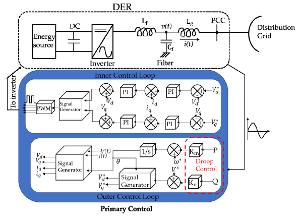
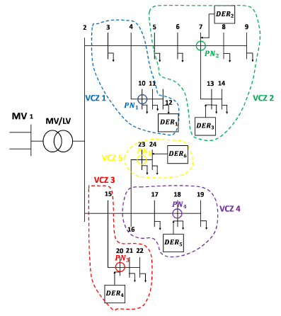
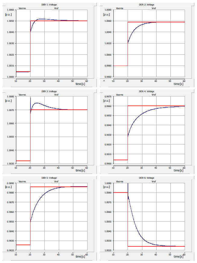
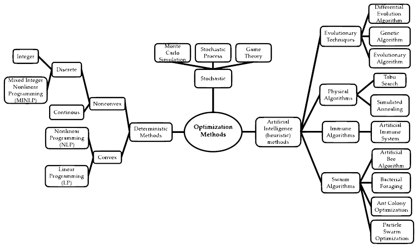
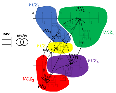
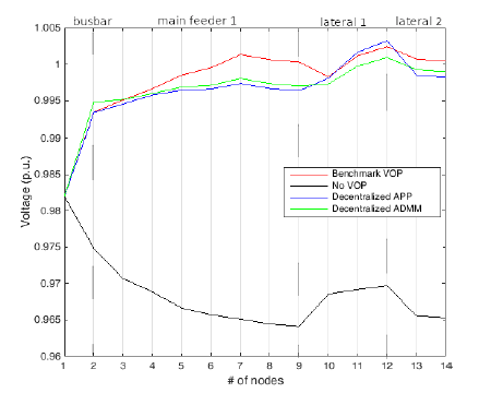
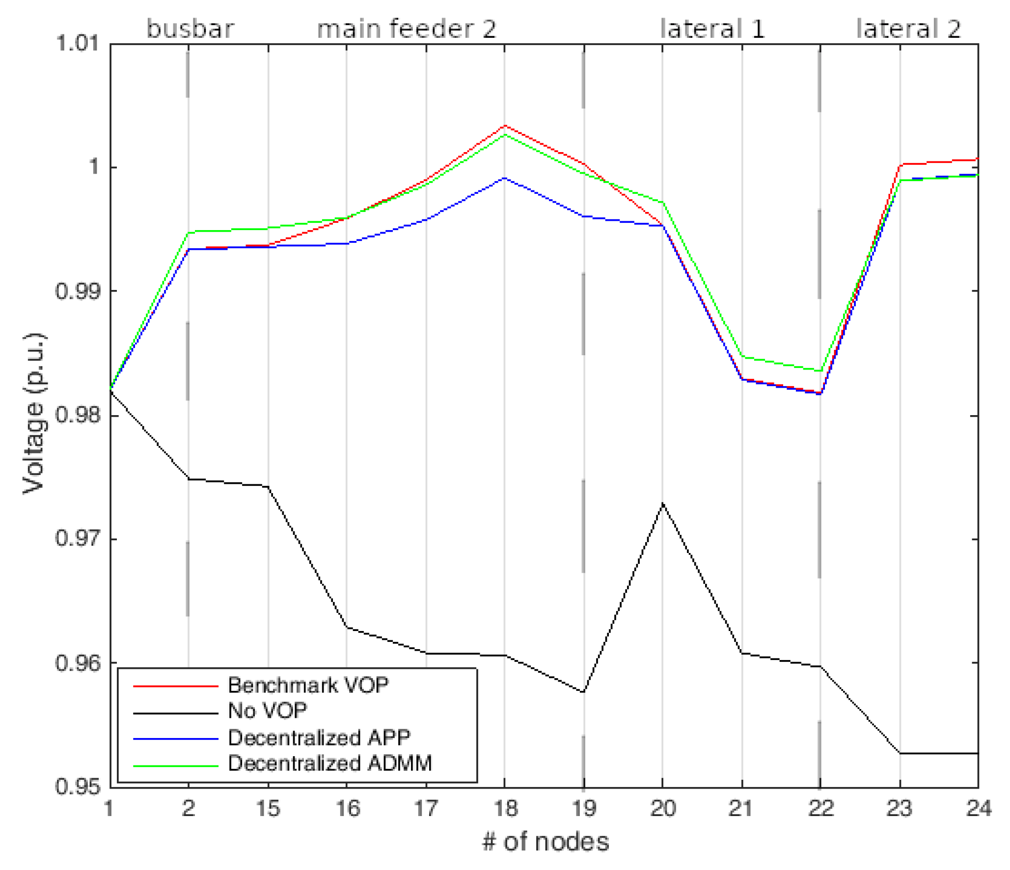
Table 1.
Parameters of the local voltage PI regulators.
| DER # | Proportional Gain [p.u.] | Integral Time Constant [s] |
| 2 | 27 | 0.06 |
| 3 | 30 | 0.05 |
| 4 | 24 | 0.06 |
| 5 | 25 | 0.05 |
| 6 | 25 | 0.06 |
Table 2.
DER nodes and Pilot Nodes allocation in the 5 VCZs.
| VCZ | DER Nodes | Pilot Node |
|---|---|---|
| 1 | 12 | 10 |
| 2 | 7, 13 | 7 |
| 3 | 20 | 20 |
| 4 | 18 | 18 |
| 5 | 24 | 23 |
Table 3.
Initial values and allowable range of variations for the active and reactive powers injected/absorbed by DERs.
Table 3.
Initial values and allowable range of variations for the active and reactive powers injected/absorbed by DERs.
| Power | ||||||
|---|---|---|---|---|---|---|
| Active | 0.005 | 0.005 | 0.005 | 0.0025 | 0.003 | 0.002 |
| (MW) | (0, 0.02) | (0, 0.03) | (0, 0.03) | (0, 0.02) | (0, 0.03) | (0, 0.02) |
| Reactive | 0.001 | 0.001 | 0.001 | 0.001 | 0.001 | 0.001 |
| (MVAr) | (−0.0113, +0.0113) | (−0.0150, +0.0150) | (−0.0188, +0.0188) | (−0.0113, +0.0113) | (−0.0113, +0.0113) | (−0.0075, +0.0075) |
Table 4.
Variations with respect to the initial operating condition of the active and reactive powers injected/absorbed by DERs for the Decentralized APP and the Decentralized ADMM.
Table 4.
Variations with respect to the initial operating condition of the active and reactive powers injected/absorbed by DERs for the Decentralized APP and the Decentralized ADMM.
| DER | Decentralized APP | Decentralized ADMM | ||
|---|---|---|---|---|
| 1 | 0.0049 | 0.0103 | 0.0024 | 0.0113 |
| 2 | −0.0001 | 0.0140 | 0.0000 | 0.0150 |
| 3 | −0.0001 | 0.0178 | 0.0000 | 0.0188 |
| 4 | 0.0175 | 0.0103 | 0.0200 | 0.0113 |
| 5 | 0.0099 | 0.0103 | 0.0118 | 0.0113 |
| 6 | 0.0053 | 0.0065 | 0.0044 | 0.0075 |
Publisher’s Note: MDPI stays neutral with regard to jurisdictional claims in published maps and institutional affiliations. |
© 2021 by the authors. Licensee MDPI, Basel, Switzerland. This article is an open access article distributed under the terms and conditions of the Creative Commons Attribution (CC BY) license (https://creativecommons.org/licenses/by/4.0/).
Share and Cite
MDPI and ACS Style
Fusco, G.; Russo, M.; De Santis, M. Decentralized Voltage Control in Active Distribution Systems: Features and Open Issues. Energies 2021, 14, 2563. https://doi.org/10.3390/en14092563
AMA Style
Fusco G, Russo M, De Santis M. Decentralized Voltage Control in Active Distribution Systems: Features and Open Issues. Energies. 2021; 14(9):2563. https://doi.org/10.3390/en14092563
Chicago/Turabian StyleFusco, Giuseppe, Mario Russo, and Michele De Santis. 2021. "Decentralized Voltage Control in Active Distribution Systems: Features and Open Issues" Energies 14, no. 9: 2563. https://doi.org/10.3390/en14092563
Note that from the first issue of 2016, this journal uses article numbers instead of page numbers. See further details here.