
Impact of Series and Parallel Connection of Macro Fiber Composite Patches in Piezoelectric Harvester on Energy Storage


Faculty of Mechanical Engineering and Robotics, AGH University of Science and Technology, al. Mickiewicza 30, 30-059 Kraków, Poland
*
Author to whom correspondence should be addressed.
Energies 2021, 14(9), 2379; https://doi.org/10.3390/en14092379
Submission received: 15 March 2021
/
Revised: 16 April 2021
/
Accepted: 19 April 2021
/
Published: 22 April 2021
(This article belongs to the Special Issue Automation and Robotics Application in Energy Systems)
Abstract
:A beam containing a piezoelectric layer or layers is used for piezoelectric harvesting from various processes. The structure of the beam is made by gluing the piezoelectric material on one side (unimorph) or both sides (bimorph) of a carrying substrate. Two piezoelectric layers, glued on both sides of the substrate, may be electrically parallel or series connected. This paper presents an experimental analysis of the impact of parallel and series connections of two Macro Fiber Composite (MFC) MFC patches in a bimorph on the charging of a capacitor. In experiments, the effective charging process of the capacitor was obtained both for parallel and series connection of two MFC patches. The bimorph with a parallel connection generated a larger capacitor charging power than the bimorph with a series connection in the range of voltage across the capacitor from 1 to 18 V. However, the bimorph with a series connection was more effective than a parallel connection for voltage across the charged capacitor from 18 to 20 V. The maximum capacitor charging power generated by the bimorph, in which two MFC patches were parallel connected, was 1.8 times larger than that generated by the bimorph with a series connection and was 3.3 times larger than that generated by a unimorph with one MFC patch. The impact of level of voltage across the capacitor on its discharging process has a significant meaning for the ratio of maximum power between bimorphs and between the bimorph and unimorph.
1. Introduction
Piezoelectric energy harvesting from processes in which mechanical energy may be wasted has recently been the subject of intensive study in the scientific field. Piezoelectric materials are used for energy harvesting from, e.g., building vibrations, the motion of machine elements, wind energy, ocean waves, acoustic energy and biomechanical reactions. Mechanical energy is converted into electric energy by the use of a device, called a harvester, in which piezoelectric material is deformed by its mechanical structure. A prismatic beam with a rectangular cross-section is one commonly used mechanical structure of the harvester. The beam, which is constructed from a carrying substrate and a piezoelectric material, is applied for energy harvesting from various processes: mechanical vibration [1,2], rotational motion [3,4] and wind energy [5,6]. Mechanical energy is converted into electric energy in a piezoelectric material, which is squeezed or stretched during beam bending. A carrying substrate is made from steel, brass, aluminum, copper or various composites. Ceramics, e.g., lead titanate zirconate [4,5]; composites made from piezoelectric ceramics and polymer matrix, e.g., Macro Fiber Composite [1,2]; and piezoelectric polymers, e.g., polyvinylidene fluoride [7], are the typical piezoelectric material used in beam manufacturing. Composites have lower efficiency in energy conversion than piezoelectric ceramics, but are more resistant than monolithic ceramic to destruction due to deformations [8].
The beam structure is made by gluing the piezoelectric material to one side (unimorph) [1,9] or both sides (bimorph) [2,10] of the carrying substrate. Two piezoelectric layers, which are glued on both sides of the substrate, may be electrically parallel or series connected [11,12,13]. Schemata of parallel and series connection of two piezoelectric layers, each of which is equipped with two electrodes, are presented in Figure 1.
Yang et al. [14] investigated the impact of parallel and series connection of Macro Fiber Composite (MFC) patches, glued on one side of a beam substrate, on the charging of a capacitor. The authors noticed that MFC patches electrically connected in parallel generate the largest charging current and concluded that this connection is the most efficient in capacitor charging. However, the authors conducted an analysis for a limited voltage range across a capacitor: from 1.8 to 3.6 V. Series connection is more effective for capacitor charging than parallel for some piezoelectric materials, e.g., polyvinylidene fluoride (PVDF) PVDF/rGO fibers [15]. Song at al. [16] observed that serial connection of MFC patches was better at producing maximum power than the parallel connection for cases of higher electrical resistance. Liao et al. [17] noticed that maximum output of electric power is the same for parallel and series connection, but optimum resistive load, current and voltage across the optimal value of resistive load are considerably different. Wang et al. [18] concluded that the value of excitation frequency for maximum output power is the same for parallel and series connections. Mohammadi et al. [19] noticed that optimum load resistance in series connection of two PZT layers in a bimorph is four times larger than the parallel connection. Zhu et al. [20] proposed a criterion for the selection of series or parallel connection for a multilayered piezoelectric bimorph, which is dependent on the comparison of applied load resistance with some critical resistance. Parallel and series configurations are also applied in the connection of several beams containing a piezoelectric layer [21,22,23]. Resistive load was applied to parallel or serial connected beams in order to obtain maximum electric power.
It should be noted that cited scientists [16,17,18,19,20] focus on the determination of optimal load resistance for which two piezoelectric layers, in bimorph, generated maximum electric power. The search for a maximum electric power for a resistive load was the main purpose realized in [21,22,23]. Electric energy, generated by parallel or series connected piezoelectric layers, was not stored. Taking into account that maximum electric power is usually achieved for specific conditions, e.g., for resonant frequency of bimorph in energy harvesting from mechanical vibration [24], harvested electric energy may not be enough to permanently supply power to any receiver. However, harvested electric energy may be stored in a capacitor [25,26] and it may be used for a periodic power supply to some receiver. Hence, in contrast to [16,17,18,19,20], this article presents experimental investigation into a bimorph containing two MFC patches, parallel and series connected, for charging a capacitor which was used for energy storage. In contrast to [14], MFC patches were glued on both sides of bimorph instead of on one side and experimental analysis was conducted for the whole range of voltage across the capacitor.
2. Laboratory Setup
Experiments were conducted in laboratory setup and consisted of three main parts: mechanical system, energy storage system and measurement system (Figure 2). The mechanical system contained a motionless part of the stand body (1), moving part of the stand body (2), slider crank mechanism (4) and tested bimorph (3). A sinusoidal displacement of the moving part of the body was generated by slider crank mechanism. Amplitude and frequency of the sinusoidal displacement could be changed during laboratory research. One (fixed) tip of the tested bimorph was mounted to the motionless part of the stand body. Displacement of the second (moved) tip of the beam was extorted by the moving part of the stand body. The manufactured bimorph had a prismatic shape with a rectangular cross-section. The beam structure consisted of a carrying substrate and two patches of Macro Fiber Composite of P2 type, which were glued on both sides of the carrying substrate (Figure 3). The carrying substrate was made from steel.
Geometric parameters of manufactured bimorph are presented in Table 1.
The energy storage system (Figure 4) consisted of two components: Graetz bridge and capacitor. Such a system is called a standard energy harvesting circuit (SEH) and is used for capacitor charging [26]. The measurement system (Figure 4) consisted of three main components: A/D Board (DaqBoard 2000-CH4), voltage amplifier (ADAM 3016) and laser sensor of displacement. Three quantities were measured during laboratory experiments: rectified voltage, voltage across the capacitor and displacement of the moved tip of the harvester beam. Input impedance of measurement instruments was equal to 300 kΩ.
3. Results
3.1. Impact of Capacitor Leakage Current on Losses Stored Energy
An impact of capacitor leakage current on losses of stored energy was determined in the first stage of laboratory research. Determination of these losses required an assumption of parallel resistance RC in the energy storage system (Figure 5).
The charging of four capacitors to about 20 V and discharging of these capacitors was realized in the first stage. Capacitors with capacitances of 250 µF, 500 µF, 1000 µF and 1500 µF were used in laboratory research. Capacitors were charged by the bimorph presented in Figure 3. The courses of voltage across tested capacitors for the discharging process are presented in Figure 6. The equivalent resistance Req for both the storage system and measurement system was calculated on the basis of Equation (1). [27]
where t is time, Vt is voltage across the capacitor, Vi is voltage across the capacitor for t = 0, C is capacitance of the capacitor.
Values of the equivalent resistance Req for each capacitor are presented in Table 2.
Taking into account that the average equivalent resistance Re (2965 kΩ) was approximately equal to the impedance of the measurement instruments (300 kΩ), the value of the capacitor leakage current was negligibly small.
3.2. Capacitor Charging by the Use of Unimorphs
The capacitor with a capacitance of 500 µF was charged by a unimorph containing one MFC patch. Laboratory research contained two experiments:
- The capacitor was charged by a unimorph containing an MFC patch glued on the upper surface of the carrying substrate;
- The capacitor was charged by a unimorph containing an MFC patch glued on the bottom surface of the carrying substrate.
Charging of the capacitor was conducted for the same parameters of sinusoidal displacement of the moved tip of the harvester beam in both experiments. Amplitude was equal to 2 mm and frequency was equal to 10 Hz. Courses of voltage across the capacitor and average charging current are presented in Figure 7a,b.
3.3. Parallel and Series Connection of MFC Patch in Bimorph
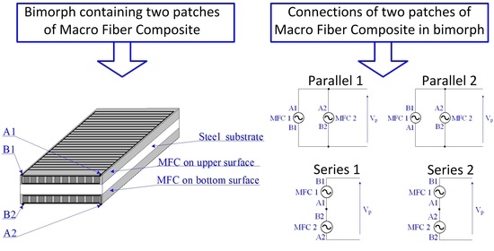
The bimorph contained two MFC patches which were glued on the upper and bottom surface of a steel substrate. Each commercial MFC patch is equipped with two points to which electrodes are connected. In laboratory experiments, these points were marked as follows (Figure 8):
- A1 connected the conduit and upper electrode in MFC glued on the upper surface of the substrate;
- B1 connected the conduit and bottom electrode in MFC glued on the upper surface of the substrate;
- A2 connected the conduit and bottom electrode in MFC glued on the bottom surface of the substrate;
- B2 connected the conduit and upper electrode in MFC glued on the bottom surface of the steel substrate.
Four connections of two MFC patches in the bimorph can be distinguished. These connections are presented in Figure 9.
3.4. Capacitor Charging by Use of Bimorph with MFC Patches Parallel and Series Connected
A capacitor with a capacitance of 500 µF was charged in our laboratory experiments. Experiments were conducted for sinusoidal displacement of the moved tip of the bimorph, in which amplitude was equal to 2 mm and frequency was equal to 10 Hz. Voltage across a capacitor and the charging current for four connections of MFC patch are presented in Figure 10.
The capacitor was effectively charged both by the bimorph with a parallel 1 connection and with a series 1 connection. In the next step, both energy stored in the capacitor and the charging power of the capacitor were calculated for a parallel 1 connection and series 1 connection on the basis of voltage across the capacitor presented in Figure 10a. Results for the bimorph were compared with energy stored in the capacitor and the charging power of the capacitor for a unimorph containing one MFC patch glued on the upper surface of the substrate. Energies and charging powers are presented in Figure 11.
3.5. Current for Capacitive Load and Resistive Load
Laboratory experiments contained two stages:
Figure 13a presents the charging current of the capacitor with a capacitance of 500 µF. Figure 13b presents the rectified current for a resistive load. Experiments were conducted for sinusoidal displacement of the moved tip of the bimorph, in which amplitude was equal to 2 mm and frequency was equal to 10 Hz. The charging current of the capacitor and the rectified current for the resistive load were generated by the use of a bimorph with a parallel 1 connection of two MFC (Figure 9a). The maximum charging current and the maximum current in the resistor were around the same. However, the courses of these current were significantly different. This was recorded from two states in the charging process of the capacitor. Charging of the capacitor and not-charging of the capacitor appeared for voltage across a capacitor equal to 5 V (Figure 13a). Charging of the capacitor and discharging of the capacitor appeared for voltage across a capacitor with 10 V, 15 V and 20 V. Discharging states and discharging current became larger for a larger voltage across the charged capacitor. The maximum value of discharging current in the capacitor was equal to 0.06 mA for the highest voltage across the charged capacitor.
Comparison between average values of rectified current for the resistive load and average values of the charging current of the capacitor are presented in Figure 14. It should be noted that the difference between these average values of current increased when the voltage increased.
4. Discussion
The courses of voltage across a capacitor and average charging current were insignificantly different in the capacitor charged by the unimorph with an MFC patch on the upper side of the steel substrate and by the unimorph with an MFC patch on the bottom side of the steel substrate. Different thicknesses of each of the bonding layers between the substrate and the particular MFC patch may be the cause of the different values in the charging current. Prasath et al. [28] noticed that bonding layer thickness has a significant effect on the coupling and electrical constants. Glue connection is a process in which the run cannot be fully predicted.
The capacitor charging process, presented in Figure 10a for four connections, was effectively realized by the use of a bimorph with both parallel 1 connection (Figure 9a) and series 1 connection (Figure 9c) of MFC patches in the bimorph. Parallel 1 connection generated a larger charging power of the capacitor than series 1 connection for most of the range (from 1 to 18 V) of voltage across the capacitor (Figure 11b). This observation is in accordance with Yang et al. [14], who noted that parallel connection is the most efficient method of charging a capacitor for voltage across the capacitor from 1.8 to 3.6 V. However, on the basis of results presented in this paper, it can be noted that series 1 connection generated a larger charging power than parallel 1 connection in the range from 18 to 20 V. Hence, series 1 connection was more effective in the capacitor charging process than parallel 1 connection for the highest voltage across a charged capacitor.
The capacitor was not effectively charged by the use of parallel 2 connection (Figure 9b) and series 2 connection (Figure 9d). Prospective values of voltage across the capacitor and charging current for series 2 connection and parallel 2 connection were equal to zero, because the voltage generated by one MFC patch was subtracted from the voltage generated by the second MFC patch for series 2 connection and the current generated by one MFC patch was subtracted from the current generated by the second MFC patch for parallel 2 connection. However, voltage across the capacitor and charging current for series 2 connection and parallel 2 connection was different from zero in laboratory experiments. Different thicknesses of bonding layers between the substrate and the particular MFC patch may be the cause of such results. The impact of voltage losses (0.7 V) in Graetz bridge diodes may be the cause of an insignificantly larger voltage across the capacitor obtained for series 2 connection of MFC patches in comparison to the voltage obtained for parallel 2 connection. The voltage produced by series 2 connection was larger than the voltage produced by parallel 2 connection; hence, voltage losses in diodes had a smaller impact on series 2 connection in comparison to parallel 2 connection.
The maximum capacitor charging power for parallel 1 connection of MFC patches was around 1.8 times larger than for series 1 connection. It was noticed that the ratio between maximum power generated by parallel and series connection for the resistive load is significantly different: Song at al. [16] observed that the maximum power produced by series connection is larger than by parallel connection; Liao et al. [17] noticed that the maximum power is around the same for parallel and series connections. Maximum charging power generated by the bimorph, in which two MFC patches were parallel connected, was around 3.3 times larger than the maximum charging power for the unimorph with one MFC patch and around 1.8 times larger than the maximum charging power for the unimorph with one MFC patch. The bimorph, in which two MFC patches were parallel 1 connected, generated more than double the maximum charging power in comparison to the unimorph, in which one MFC patch was used. The impact of the level of voltage across the capacitor on its charging process has a significant meaning for the ratio between maximum power for a bimorph and unimorph (Figure 13a). On the basis of Figure 13a, it can be said that the capacitor was charged when the voltage generated by bimorph was larger than the voltage across the charged capacitor. However, the capacitor was discharged when the voltage generated by bimorph or unimorph decreased below the voltage across the capacitor. This observation is in contrast to Wang et al. [29], who noticed that capacitor charging by piezoelectric patch is not a continuous process, enumerating two states: charging and not-charging of the capacitor. For particular levels of voltage across a capacitor, the time of capacitor discharging for a bimorph with parallel MFC’s (Figure 13a), a bimorph with series MFC’s and a unimorph are different. A comparison of the charging and discharging processes for bimorph with series MFC’s and unimorph is presented in Figure 15.
The bimorph with parallel connection generated larger voltage than the bimorph with series connection and the unimorph; hence, the time of capacitor discharging was shorter for the bimorph with parallel connection in comparison to the bimorph with series connection and the unimorph.
It should be noted that the capacitor was discharged because resistive losses appeared in the measurement system. Discharging current from the capacitor was a result of input impedance from measurement instruments. Dalzell at al. [30] noticed that the input impedance of measurement instruments should be taken into account in theoretical predictions of the rectified response for the resistive load of a piezoelectric harvesting system. Input impedance must also be taken into account for the capacitive load of a piezoelectric harvester. Input impedance of measurement instruments, which was equal to 300 kΩ in laboratory research, caused the capacitor to discharge current which was equal to 0.06 mA for voltage across the charged capacitor equal to 20 V, 0.05 mA for 15 V and 0.03 mA for 10 V. The value of the discharging current increased when voltage across the capacitor increased.
5. Conclusions
The effective charging process of a capacitor can be obtained both for parallel and series connection of two MFC patches in a bimorph. The bimorph with a parallel connection generated larger charging power of the capacitor than the bimorph with a series connection for most of voltage range across the capacitor. However, the bimorph with a series connection was more effective in the capacitor charging process than in parallel connection for the highest voltage across a charged capacitor.
The maximum capacitor charging power generated by the bimorph, in which two MFC patches are parallel connected, was 1.8 times larger than that generated by the bimorph with a series connection and was 3.3 times larger than that generated by the unimorph with one MFC patch. The impact of the level of voltage across the capacitor on its charging process has a significant meaning for the ratio among maximum power for a bimorph with parallel MFCs, a bimorph with series MFCs and a unimorph. The capacitor was discharged when voltage generated by the bimorph or unimorph decreased below the voltage across the capacitor. The bimorph with parallel MFCs generated larger voltage than the bimorph with series MFCs and the unimorph, hence the capacitor discharging process had a smaller impact for the bimorph with parallel MFCs in comparison to the bimorph with series MFC’s and the unimorph.
Author Contributions
Conceptualization, D.G. and P.M.; methodology, D.G. and P.M.; investigation, P.M. and D.G.; writing—original draft preparation, D.G.; writing—review and editing, D.G.; supervision, D.G. All authors have read and agreed to the published version of the manuscript.
Funding
This research was funded by the AGH University of Science and Technology within the scope of the research program No. 16.16.130.942 and Initiative for Excellence—Research University at AGH UST.
Institutional Review Board Statement
Not applicable.
Informed Consent Statement
Not applicable.
Data Availability Statement
Data is contained within the article.
Conflicts of Interest
The authors declare no conflict of interest.
References
- Machado, S.P.; Febbo, M.; Gatti, C.D.; Osinaga, S.M. A piezoelectric beam model with geometric, material and damping nonlinearities for energy harvesting. Smart Mater. Struct. 2020, 29, 095009. [Google Scholar] [CrossRef]
- Khazaee, M.; Rezaniakolaie, A.; Rosendahl, L.A. broadband macro-fiber-composite piezoelectric energy harvester for higher energy conversion from practical wideband vibrations. Nano Energy 2020, 76, 104978. [Google Scholar] [CrossRef]
- Zhang, J.; Fang, Z.; Shu, C.; Zhang, J.; Zhang, Q.; Li, C. A rotational piezoelectric energy harvester for efficient wind energy harvesting. Sens. Actuators A Phys. 2017, 262, 123–129. [Google Scholar] [CrossRef]
- Machado, S.P.; Febbo, M.; Ramírez, J.M.; Gatti, C.D. Rotational double-beam piezoelectric energy harvester impacting against a stop. J. Sound Vib. 2020, 469, 115141. [Google Scholar] [CrossRef]
- Zhou, M.; Chen, Q.; Xu, Z.; Wang, W. Piezoelectric wind energy harvesting device based on the inverted cantilever beam with leaf-inspired extensions. AIP Adv. 2019, 9, 035213. [Google Scholar] [CrossRef] [Green Version]
- Elahi, H.; Eugeni, M.; Fune, F.; Lampani, L.; Mastroddi, F.; Paolo Romano, G.; Gaudenzi, P. Performance evaluation of a piezoelectric energy harvester based on flag-flutter. Micromachines 2020, 11, 933. [Google Scholar] [CrossRef]
- Li, S.; Crovetto, A.; Peng, Z.; Zhang, A.; Hansen, O.; Wang, M.; Wang, F. Bi-resonant structure with piezoelectric PVDF films for energy harvesting from random vibration sources at low frequency. Sens. Actuators A Phys. 2016, 247, 547–554. [Google Scholar] [CrossRef] [Green Version]
- Dai, Q.; Ng, K. Investigation of electromechanical properties of piezoelectric structural fiber composites with micromechanics analysis and finite element modeling. Mech. Mater. 2012, 53, 29–46. [Google Scholar] [CrossRef]
- Mo, C.; Kim, S.; Clark, W.W. Theoretical analysis of energy harvesting performance for unimorph piezoelectric benders with interdigitated electrodes. Smart Mater. Struct. 2009, 18, 055017. [Google Scholar] [CrossRef]
- Wang, H.; Meng, Q. Analytical modeling and experimental verification of vibration-based piezoelectric bimorph beam with a tip-mass for power harvesting. Mech. Syst. Signal Process. 2013, 36, 193–209. [Google Scholar] [CrossRef]
- Zhao, S.; Erturk, A. Electroelastic modeling and experimental validations of piezoelectric energy harvesting from broadband random vibrations of cantilevered bimorphs. Smart Mater. Struct. 2012, 22, 015002. [Google Scholar] [CrossRef]
- Lumentut, M.F.; Howard, I.M. Analytical and experimental comparisons of electromechanical vibration response of a piezoelectric bimorph beam for power harvesting. Mech. Syst. Signal Process. 2013, 36, 66–86. [Google Scholar] [CrossRef] [Green Version]
- Kuo, C.L.; Lin, S.C.; Wu, W.J. Fabrication and performance evaluation of a metal-based bimorph piezoelectric MEMS generator for vibration energy harvesting. Smart Mater. Struct. 2016, 25, 105016. [Google Scholar] [CrossRef]
- Yang, Y.; Tang, L.; Li, H. Vibration energy harvesting using macro-fiber composites. Smart Mater. Struct. 2009, 18, 115025. [Google Scholar] [CrossRef]
- Mokhtari, F.; Spinks, G.M.; Sayyar, S.; Cheng, Z.; Ruhparwar, A.; Foroughi, J. Highly Stretchable Self-Powered Wearable Electrical Energy Generator and Sensors. Adv. Mater. Technol. 2021, 6, 2000841. [Google Scholar] [CrossRef]
- Song, H.J.; Choi, Y.T.; Wereley, N.M.; Purekar, A.S. Energy harvesting devices using macro-fiber composite materials. J. Intell. Mater. Syst. Struct. 2010, 21, 647–658. [Google Scholar] [CrossRef]
- Liao, Y.; Sodano, H.A. Modeling and comparison of bimorph power harvesters with piezoelectric elements connected in parallel and series. J. Intell. Mater. Syst. Struct. 2010, 21, 149–159. [Google Scholar] [CrossRef]
- Wang, L.; Zhao, L.; Jiang, Z.; Luo, G.; Yang, P.; Han, X.; Li, X.; Maeda, R. High accuracy comsol simulation method of bimorph cantilever for piezoelectric vibration energy harvesting. AIP Adv. 2019, 9, 095067. [Google Scholar] [CrossRef]
- Mohammadi, S.; Cheraghi, K.; Khodayari, A. Piezoelectric vibration energy harvesting using strain energy method. Eng. Res. Express 2019, 1, 015033. [Google Scholar] [CrossRef]
- Zhu, Y.K.; Yu, Y.G.; Li, L.; Jiang, T.; Wang, X.Y.; Zheng, X.J. Modeling and characterization of multilayered d15 mode piezoelectric energy harvesters in series and parallel connections. Smart Mater. Struct. 2016, 25, 075027. [Google Scholar] [CrossRef]
- Lien, I.C.; Shu, Y.C. Array of piezoelectric energy harvesting by the equivalent impedance approach. Smart Mater. Struct. 2012, 21, 082001. [Google Scholar] [CrossRef] [Green Version]
- Al-Ashtari, W.; Hunstig, M.; Hemsel, T.; Sextro, W. Enhanced energy harvesting using multiple piezoelectric elements: Theory and experiments. Sens. Actuators A Phys. 2013, 200, 138–146. [Google Scholar] [CrossRef]
- Wu, P.H.; Lin, J.T.; Lo, Y.C.; Shu, Y.C. An SECE array of piezoelectric energy harvesting. Smart Mater. Struct. 2021, 30, 045008. [Google Scholar] [CrossRef]
- Grzybek, D. Piezoelectric generator for the Power Supply of the Monitoring System. In Proceedings of the 2014 15th International Carpathian Control Conference (ICCC), Velke Karlovice, Czech Republic, 28–30 May 2014; pp. 135–138. [Google Scholar]
- Bagheri, S.; Wu, N.; Filizadeh, S. Modeling of capacitor charging dynamics in an energy harvesting system considering accurate electromechanical coupling effects. Smart Mater. Struct. 2018, 27, 065026. [Google Scholar] [CrossRef]
- Zhang, Z.; Xiang, H.; Tang, L. Modeling, analysis and comparison of four charging interface circuits for piezoelectric energy harvesting. Mech. Syst. Signal Process. 2021, 152, 107476. [Google Scholar] [CrossRef]
- Niu, J.; Conway, B.E.; Pell, W.G. Comparative studies of self-discharge by potential decay and float-current measurements at C double-layer capacitor and battery electrodes. J. Power Source 2004, 135, 332–343. [Google Scholar] [CrossRef]
- Prasath, S.S.; Arockiarajan, A. Influence of bonding layer on effective electromechanical properties of macro-fiber composites (MFCs). Smart Mater. Struct. 2014, 23, 095046. [Google Scholar] [CrossRef]
- Wang, Q.; Wu, N. Optimal design of a piezoelectric coupled beam for power harvesting. Smart Mater. Struct. 2012, 21, 085013. [Google Scholar] [CrossRef]
- Dalzell, P.; Bonello, P. Analysis of an energy harvesting piezoelectric beam with energy storage circuit. Smart Mater. Struct. 2012, 21, 105029. [Google Scholar] [CrossRef]
Figure 1.
Electric connections of two piezoelectric layers in bimorph: (a) parallel; (b) Series.

Figure 2.
Main parts of laboratory stand.

Figure 3.
Structure of manufactured bimorph.

Figure 4.
Structure of storage system and measurement system.

Figure 5.
Parallel resistance in energy storage system.

Figure 6.
Course of voltage across the capacitors for discharging process.

Figure 7.
Charging of capacitor: (a) voltage across a capacitor; (b) average charging current.

Figure 8.
Conduit connections in MFC patches.

Figure 9.
Connections of two MFC patches in bimorph: (a) parallel 1; (b) parallel 2; (c) series 1; (d) series 2.
Figure 9.
Connections of two MFC patches in bimorph: (a) parallel 1; (b) parallel 2; (c) series 1; (d) series 2.

Figure 10.
Capacitor charging by use of bimorph: (a) voltage across a capacitor; (b) average charging current.
Figure 10.
Capacitor charging by use of bimorph: (a) voltage across a capacitor; (b) average charging current.

Figure 11.
Characteristics of capacitor charging process: (a) energy stored in capacitor; (b) charging power of capacitor.
Figure 11.
Characteristics of capacitor charging process: (a) energy stored in capacitor; (b) charging power of capacitor.

Figure 12.
Load of bimorph: (a) capacitive; (b) resistive.

Figure 13.
Current courses: (a) for capacitive load; (b) for resistive load.

Figure 14.
Average current for capacitive and resistive load of bimorph.

Figure 15.
Current courses: (a) for unimorph; (b) for bimorph with series connection.


Table 1.
Geometric parameters of bimorph (values in mm).
| Parameters | Symbol | Value |
|---|---|---|
| Length of piezoelectric area inside MFC patch | lp | 85 |
| Overall length of MFC patch | lMFC | 100 |
| Width of piezoelectric area in MFC patch | wp | 14 |
| Width of steel substrate | wb | 16 |
| Thickness of MFC patch | tMFC | 0.3 |
| Thickness of steel substrate | tb | 2 |
| Distance between fixed tip and moved tip | lke | 105 |
Table 2.
The equivalent resistance for storage and measurement systems.
| Quality | Unit | Value | |||
|---|---|---|---|---|---|
| Capacitor capacitance C | µF | 250 | 500 | 1000 | 1500 |
| Equivalent resistance Req | kΩ | 298 | 297 | 296 | 295 |
Publisher’s Note: MDPI stays neutral with regard to jurisdictional claims in published maps and institutional affiliations. |
© 2021 by the authors. Licensee MDPI, Basel, Switzerland. This article is an open access article distributed under the terms and conditions of the Creative Commons Attribution (CC BY) license (https://creativecommons.org/licenses/by/4.0/).
Share and Cite
MDPI and ACS Style
Grzybek, D.; Micek, P. Impact of Series and Parallel Connection of Macro Fiber Composite Patches in Piezoelectric Harvester on Energy Storage. Energies 2021, 14, 2379. https://doi.org/10.3390/en14092379
AMA Style
Grzybek D, Micek P. Impact of Series and Parallel Connection of Macro Fiber Composite Patches in Piezoelectric Harvester on Energy Storage. Energies. 2021; 14(9):2379. https://doi.org/10.3390/en14092379
Chicago/Turabian StyleGrzybek, Dariusz, and Piotr Micek. 2021. "Impact of Series and Parallel Connection of Macro Fiber Composite Patches in Piezoelectric Harvester on Energy Storage" Energies 14, no. 9: 2379. https://doi.org/10.3390/en14092379
Note that from the first issue of 2016, this journal uses article numbers instead of page numbers. See further details here.