
Grid-Connected PV Systems Controlled by Sliding via Wireless Communication
by
 ,
,
Juan M. Cano
, 
Aranzazu D. Martin
*,
Reyes S. Herrera
,
Jesus R. Vazquez
and
Francisco Javier Ruiz-Rodriguez
Department of Electrical and Thermal Engineering, Design and Projects, University of Huelva, 21007 Huelva, Spain
*
Author to whom correspondence should be addressed.
Energies 2021, 14(7), 1931; https://doi.org/10.3390/en14071931
Submission received: 22 February 2021
/
Revised: 20 March 2021
/
Accepted: 26 March 2021
/
Published: 31 March 2021
(This article belongs to the Special Issue Electrical Power Engineering: Efficiency and Control Strategies)
Abstract
:Grid-connected photovoltaic (PV) systems are designed to provide energy to the grid. This energy transfer must fulfil some requirements such as system stability, power quality and reliability. Thus, the aim of this work is to design and control a grid-connected PV system via wireless to guarantee the correct operation of the system. It is crucial to monitor and supervise the system to control and/or detect faults in real time and in a remote way. To do that, the DC/DC converter and the DC/AC converter of the grid-connected PV system are controlled wirelessly, reducing costs in cabling installations. The used control methods are the sliding for the DC/DC converter and the Proportional-Integral (PI) for the inverter. The sliding control is robust, ensures system stability under perturbations, and is proven to work well via wireless. The PI control is simple and effective, proving its validity through wireless too. In addition, the effect of the communications is analysed in both controllers. An experimental platform has been built to conduct the experiments to verify the operation of the grid-connected PV system remotely. The results show that the system operates well, achieving the desired values for the maximum power point tracker (MPPT) sliding control and the energy transfer from the inverter to the grid.
1. Introduction
In recent years, consumption has exhibited a trend towards growth. The ideal would be to provide the energy through renewable energies instead of conventional energies, reducing CO2 emissions and using unlimited resources with zero fuel costs. Photovoltaic technology, after hydro and wind, has been consolidated as the third most widespread renewable energy. The PV systems can be classified as stand-alone PV energy systems and grid-connected PV systems. The stand-alone PV systems are usually used when there is no access to the grid and the energy produced is stored in batteries to guarantee the supply. Initially, the grid-connected PV systems were used in big areas to produce a large amount of energy although nowadays these systems are gradually growing as self-consumption systems too, within the distribution generation framework. Thus, they can be installed as generation systems in conventional housing, neighborhood associations, shopping centers, or industrial environments.
This work is focused on the grid-connected PV systems to provide energy to the grid. However, the integration of the PV technologies into power systems involves some drawbacks due to the fluctuation of the solar generation and the electronic equipment required to convert and transfer the energy to the grid. Thus, the operation of these kind of systems should guarantee the stability, power quality, and reliability of the grid. To do that, it is necessary to implement appropriate methods to diagnose and detect faults, supervise, monitor, and control the operation of the grid. In addition, it is crucial to develop techniques to manage the grid operation in real time. Techniques of faults diagnosis and detection have been developed by different authors through learning machines [1,2], using current-voltage curves and environmental conditions [3], or fuzzy logic [4], amongst others [5,6]. The monitoring and supervision are also very important within the system operation. The different works focused on different technologies, although the vast majority of them uses wireless sensor networks [7], by means of the standard Open Platform Communications (OPC) [8] or ZigBee [9].
Regarding the communication system, there is a variety of wireless data transmission technologies. The most used so far is the wired communication. Nevertheless, one of the objectives of this work is to replace the conventional wired controlled system by wireless communication. One of the most used communication systems in the world is the satellite communication [10], 2G [11], or 3G [12]. Other technologies as radio-frequency communication can also be used [13]. There are other technologies that use short range communication, such as ZigBee [14,15], Bluetooth [12], or Wi-Fi [12]. Wi-Fi communication is the selected one for this work because it is crucial to achieve precise measurements of the sensors in real-time to reach the maximum power point (MPP) ensuring the reliable operation of the grid-connected PV system and this type of communication can guarantee it. In addition, this technology ensures robustness even with the interferences that the wireless communication can cause and it also guarantees low latency, precise data acquisition and low power consumption. ZigBee is similar to Wi-Fi communication but when a tight latency and reliability is required, Wi-Fi communication is preferred. Another advantage of the Wi-Fi communication is that it is able to reach 300 m whereas ZigBee has a maximum range of 100 m. Thus, a control by means of Wi-Fi is possible facilitating a real-time and remote operation. In addition, there is a cost reduction since the vast majority of the cabling is not required in Wi-Fi communication.
Another crucial aspect for the correct operation of the system is the control. The control is required to transfer the energy from the PV modules to the grid in appropriate conditions. Different works develop a wide range of control methods [16], but they are not focused on the implementation through wireless communication. Nowadays, the controllers are implemented in remote control centers, facilitating the monitoring, supervision and detection of faults. Then, the signals are sent to a base station, where the control is implemented, to calculate all the required values for the correct operation and sent them back to the PV plant again. In this work, we propose the control of a grid-connected PV system by means of wi-fi. The wireless communication increases the level of noise. Thus, the communication effect requires to be analysed to guarantee the robustness and stability of the system. The control through Wi-Fi communication has been already studied in a stand-alone PV system [17], analysing the effect of the communication in the DC/DC converter control. This work innovates studying the wi-fi effect in the controller of the DC/DC converter and the DC/AC converter which injects power to the grid accomplishing the power quality requirements amongst others (signals synchronization, maximum energy transfer, control stability, robustness).
Regarding the DC/DC converter, there are different topologies. The most usual DC/DC converter used in PV systems is the boost converter [18], since it can rise the output voltage. In this work, a buck-boost converter is used, due to the possibility of increasing or decreasing the voltage at the output. This converter is advantageous when a required range of voltage is needed with telecom loads [19]. Thus, the maximum power point tracking (MPPT) algorithm is implemented in the buck-boost converter. There are many MPPT methods, from the simplest ones as the Perturb and Observe [20], or the Incremental Conductance [20], to the most complex such as fuzzy logic [21], neural network [16], Particle Swarm Optimization [22], or backstepping control [19], amongst others [23]. All the methods differ in the MPPT efficiency, convergence speed, complexity, number of sensors, or the effect of the perturbations [24]. In this work, a sliding mode control (SMC) is proposed and applied to a buck-boost converter [17]. This non-linear controller, which is robust and stable under perturbations, tracks the reference voltage that provides the maximum power point (MPP) [17,25,26].
The grid-connected PV system requires the connection of a DC/AC converter to inject energy to the grid. The inverter plays an important role in grid synchronization for the correct operation of the system [27,28]. The DC/AC converter produces high order harmonic that affect the voltage power quality. Thus, it is required to inject the signals taking into consideration the power quality and the stability of the grid, using harmonic filters [28], to decrease the current harmonics, the voltage distortion or to compensate reactive power. In this work, a passive filter with an inductor connected at the inverter output is used. According to the DC/AC converter controller, there are many methods [29,30,31,32]. In this work, a PI control is used due to its simplicity and effectiveness to transfer energy from the PV modules to the grid.
The paper is organized as follows. In Section 2 the PV system is presented, where the different components of the grid-connected PV system are described, Section 3 presents the controllers for the DC/DC converter and the DC/AC converter, whereas Section 4 describes the experimental platform and the experimental results. Then, the discussion is presented in Section 5, and finally, the conclusions are drawn in Section 6.
2. The Grid-Connected PV System Configuration
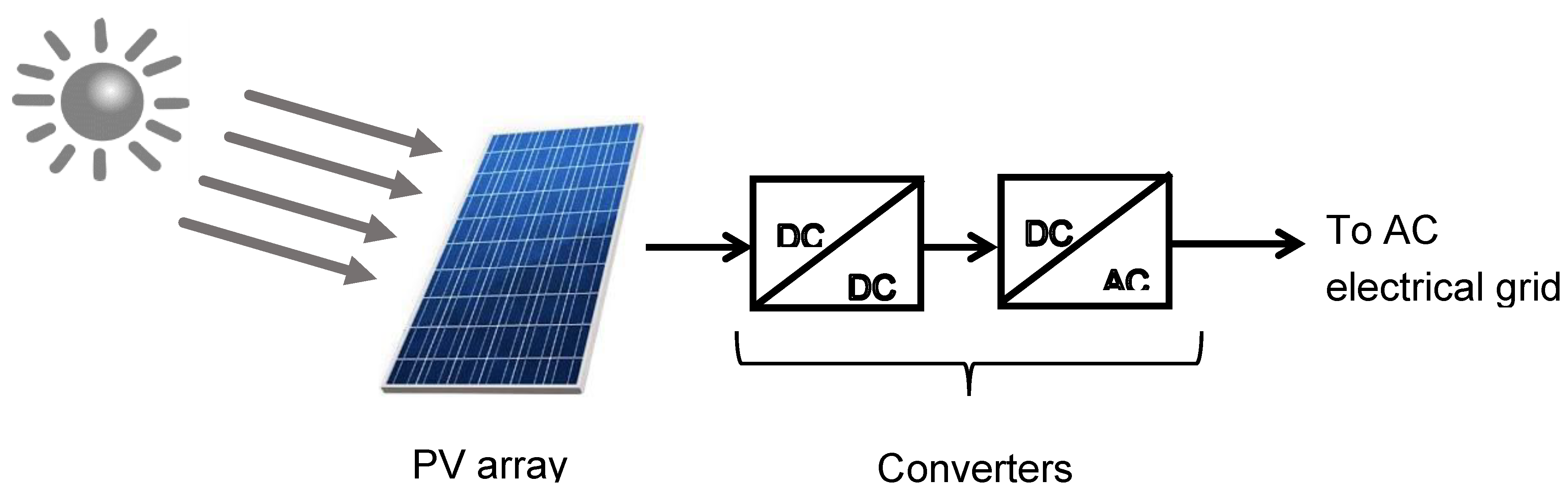
In this section, the configuration of the system proposed in this paper is presented. It is constituted by a photovoltaic array connected to the grid through a DC/DC converter, which makes the maximum power point tracking, and a DC/AC converter, which makes the synchronization to the grid voltage, Figure 1.
The voltage at the input of the DC/AC converter is constant and its value is kept to the set point while the voltage at the input of DC/DC converter changes with the corresponding to the maximum power point. The algorithm used is the sliding controller. The converter DC/AC generates a waveform synchronized to the voltage grid with an easy PI controller.
2.1. The PV Module
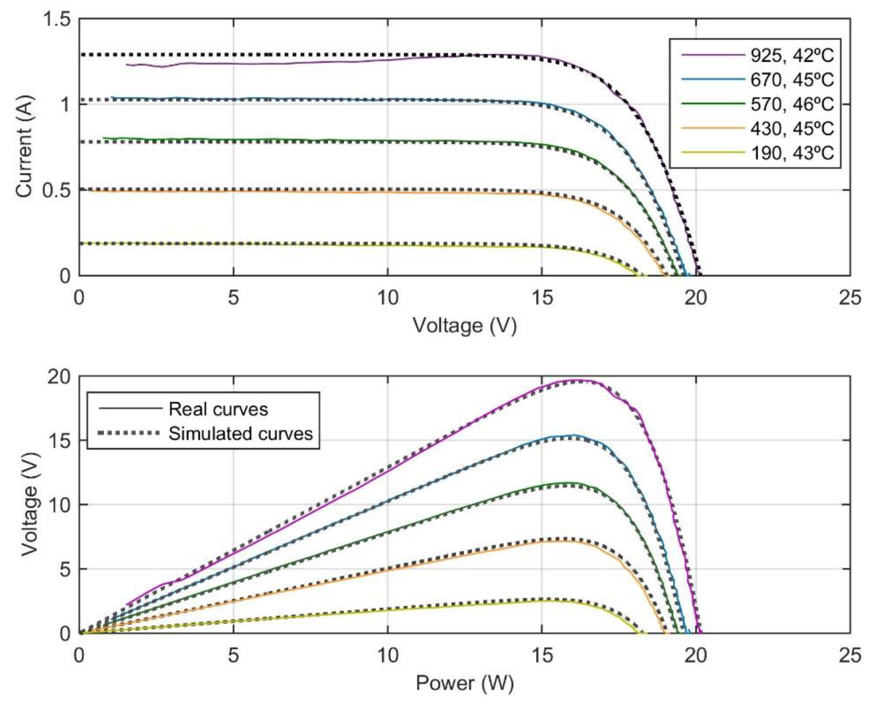
The photovoltaic array used in the proposed system is a commercial one, with a maximum power of 20 W. The voltage that provides the maximum power is 17.5 V and the current at the maximum power point is 1.15 A. The PV module open-circuit voltage is 21.6 V and the short-circuit current is 1.28 A. The corresponding characteristic curves are shown in Figure 2 for different values of irradiance and temperature.
2.2. The DC/DC Converter
Regarding the DC/DC converter, the buck-boost configuration [17,19], has been chosen, instead of the boost, which is the most used in the technical literature. The main reason is that the buck-boost allows the decreasing of the voltage, as well as the increasing. Thus, they can be used in applications with loads which works at low voltages, as for example those related to communications. The configuration of a buck-boost converter is presented in Figure 3, where vPV is the PV output voltage and the voltage at the input of the converter, in V, iPV, in A, is the solar array output current, iL, in A, is the inductor current and v0, in V, is the buck-boost converter output voltage, which is the same as the voltage at the input of the DC/AC converter. The DC/DC converter output current is io, in A. L is an inductor with a value of 20 mH, C1 is the filtering capacitor with a value of 1000 μF and C is the output capacitor which has a value of 5700 μF. The used diode is a MBR10200 and the MOSFET is a CSD19536KCS device driven by an FOD3180 driver. The values of all these elements are constants.
The switch ON/OFF commutation generates the duty cycle D = tON/tC, being tON the time ON (u = 1) and tC the switching period (0 < D < 1). The voltage output/input ratio is as expressed in Equation (1).
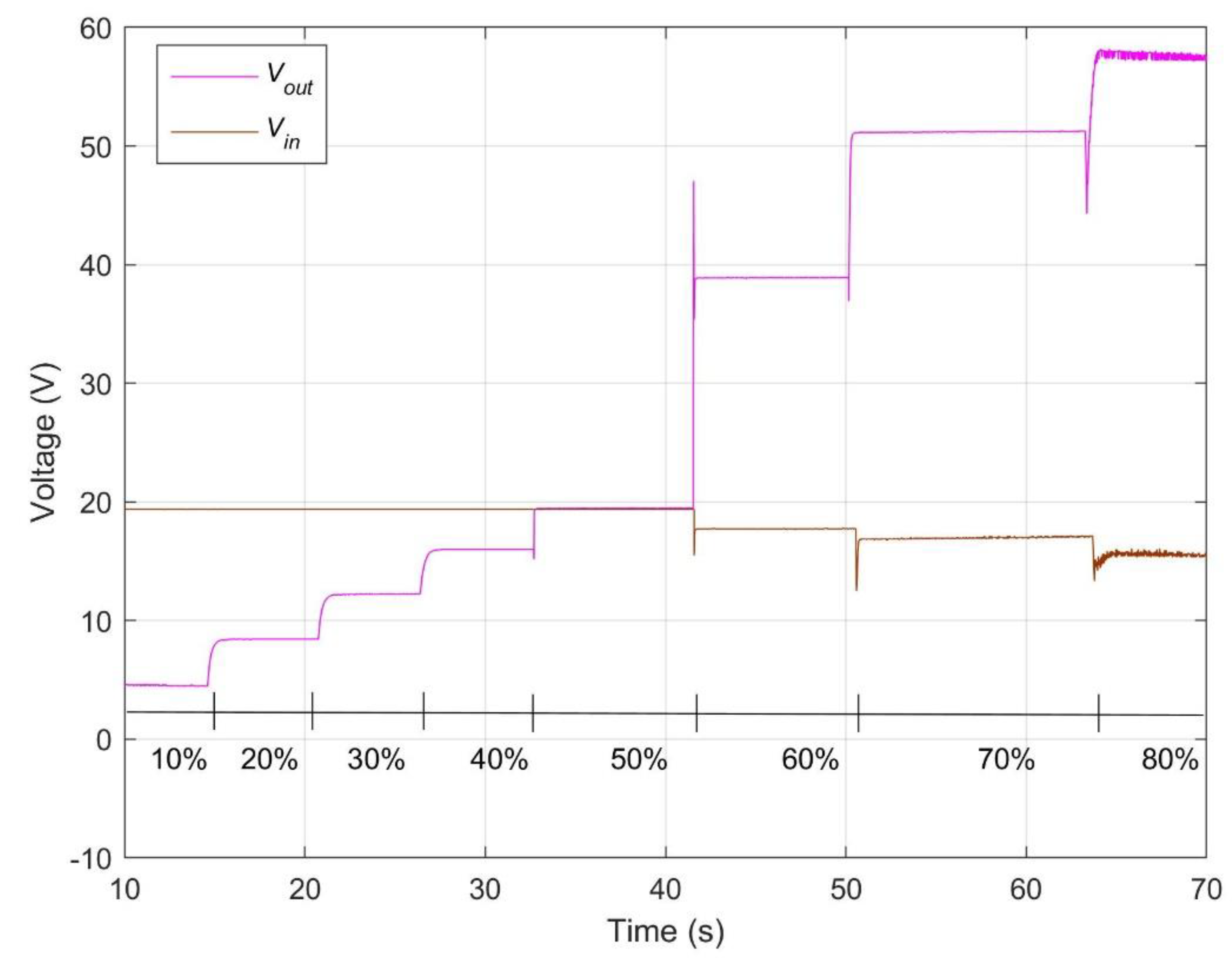
The transistor commutation is established by means of a pulse width modulation (PWM) method. The input and output voltages present opposite polarity. The input and output voltages corresponding to different D values are presented in Figure 4.
2.3. The DC/AC Converter
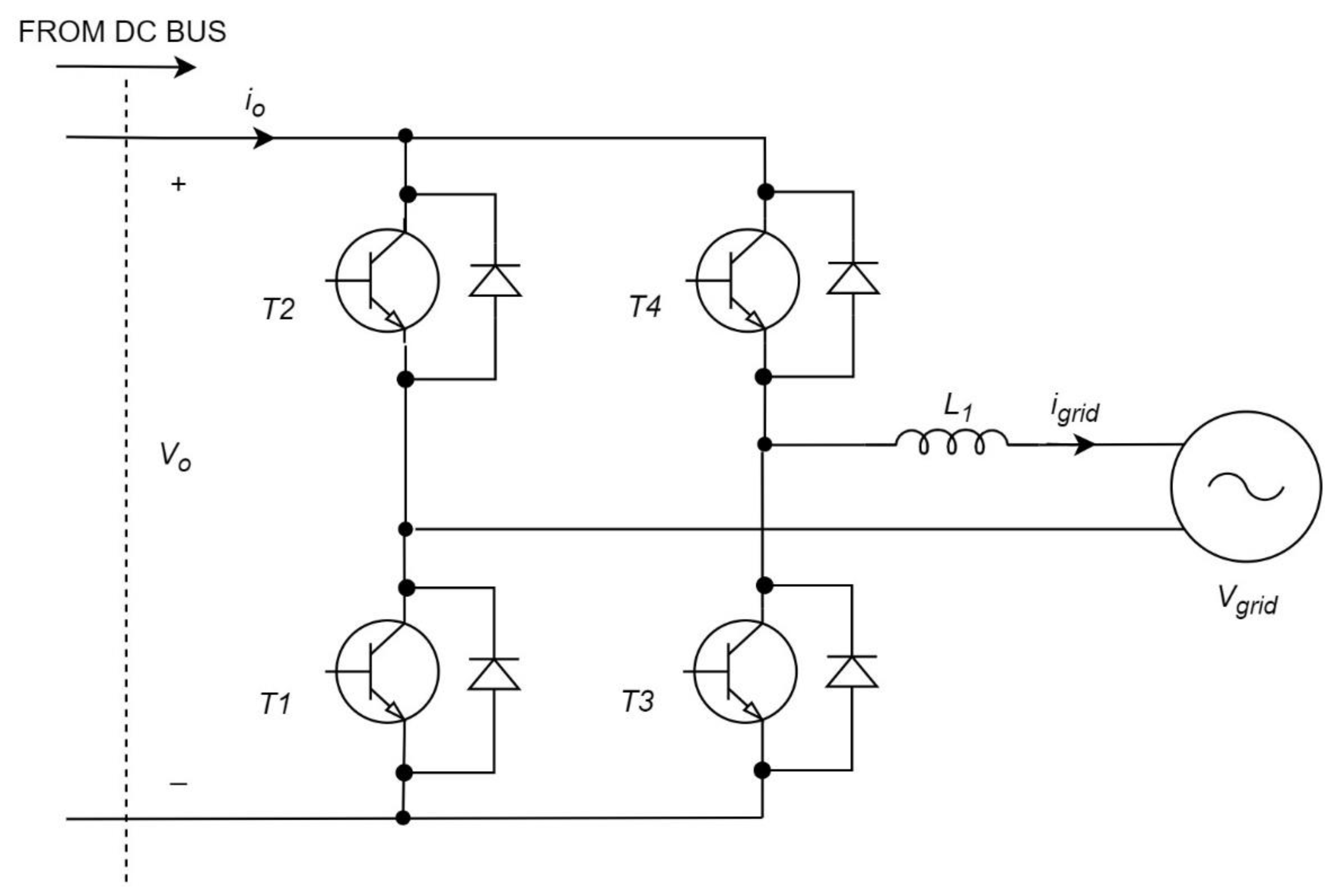
After the DC stage, a DC/AC inverter is used to inject the extracted photovoltaic power to the electrical AC grid, converting the direct current to alternating current by means of the transistors’ commutation. In this work, a single-phase DC/AC converter is used. Figure 5 shows the inverter power block topology including four insulated-gate bipolar transistors (IGBT) branches with anti-parallel diodes. The IGBTs are IRGB4062DPB devices whereas the diodes are driven by IR2106 devices.
The AC output is connected to the grid through a reactance of 20 mH to implement the current control. The output current measurements are compared with the reference ones, in phase with the load voltages to inject only active power to the AC system, and a PI control calculates the adequate IGBT trigger signals.
3. The DC/DC Converter and DC/AC Converter Controllers
This section explains the buck-boost converter controller used to track the MPP and control the DC/DC converter as well as the inverter controller to transfer the maximum energy to the grid fulfilling its requirements.
3.1. DC/DC Converter Sliding Controller
There are numerous studies up to now about the control algorithm implemented in the DC/DC converter to track the PV maximum power point while maintaining a constant output voltage. The results of the backstepping algorithm are presented in [19], where results show that the algorithm guarantees the tracking of the PV maximum power point with different weather conditions and the answer of the algorithm is good.
However, in this work, it is proposed to test another algorithm to improve the controller dynamic behavior: the non-linear sliding control method which is a variable structure controller (VSC). This algorithm has already been used in [13] in islanding systems. In this new case, the sliding control will be applied to the buck-boost converter, connected between the PV array and the DC/AC converter.
The wide operating range allowed by the sliding control increases the DC/DC converter dynamic performance. The high-speed switching law used by the control, makes the system go to a switching function (also denominated sliding surface). In addition, the control makes the system stay in the surface. The value of the DC/DC converter elements and the equations corresponding to the switching surface determine the system dynamic behavior, which is robust under changes of the parameter and/or disturbances.
The buck-boost equations, using the state averaging method and the D parameter, working in continuous conduction mode (CCM) are presented in Equations (2)–(5).
where and is the reference voltage to be reached.
Equations (2)–(5) can be expressed in matrix form, Equation (6).
Matrices are presented in Equations (7)–(10).
The surface appropriate for the studied application is proposed in Equation (11). The trajectories around that surface should converge to it and stay on the sliding surface. The proposed switching function guarantees the voltage regulation of the buck-boost converter.
where k1 and k2 are the sliding design parameters. The condition for the sliding surface existence if S(x) = dS/dt = 0. To define the sliding surface, a control law must be found, which also assures the sliding mode. The control input is composed of two components called corrective control, Dc, and equivalent control, Deq, Equation (12).
Equation (13) express, in a typical way for this controller, the corrective control, which compensates the deviations from the sliding surface.
where must be positive. Equation (14) defines the sign of the sliding surface.
Equation (15) presents the control which makes the sliding surface null to remain on the sliding surface.
Including Equations (5) and (11)–(13) in (15), Equation (16) is obtained.
This must fulfill Equations (17)–(19).
The inductor current (x2) is always positive because the DC/DC converter is CCM. In addition, if k1 and k2 are positive, the output voltage, x3, is always negative.
A null vale for S means a globally asymptotically stable system. Thus, the control is achieved by means of Equations (12), (13) and (15), per Equation (20).
To make the systems fix to the sliding surface and stay on it, a Lyapunov function is used, Equation (21).
The value of D has to make negative definite the time derivative of the Lyapunov function, which has to fulfill Equation (22).
The sliding surface time derivative can be calculated applying Equation (23).
The time derivative of the Lyapunov function yields Equation (24).
The expression between brackets has to be solved, Equation (25).
The first term is considered null and Equation (24) converts to Equation (26).
The last term is negative. So, Equations (27) and (28) are obtained.
These two equations close the sliding control.
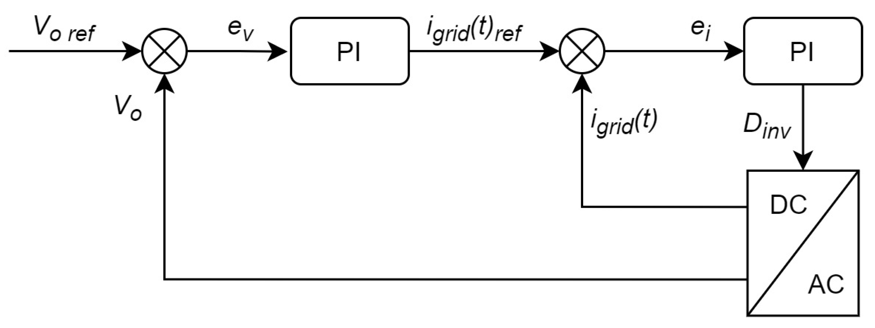
3.2. DC/AC Converter PI Controller
The inverter must inject nearly sinusoidal current and the current must be co-linear with the grid voltage. Thus, the power quality is guaranteed, reducing the harmonic distortion. In this work, a PI controller is used because is easy to implement and it works appropriately. Figure 6 depicts the PI control scheme, where there are two control loops. The inner control loop is for the current and it compares the grid reference current with the measured current obtained through the reactance whereas the outer loop is for the voltage and it compares the buck-boost converter output voltage (or the inverter input voltage) with the reference voltage to remain this voltage almost constant. Thus, the PI control achieves the adequate duty cycle to make the inverter injects the proper current to the grid.
4. Experimental Results
4.1. Experimental Platform
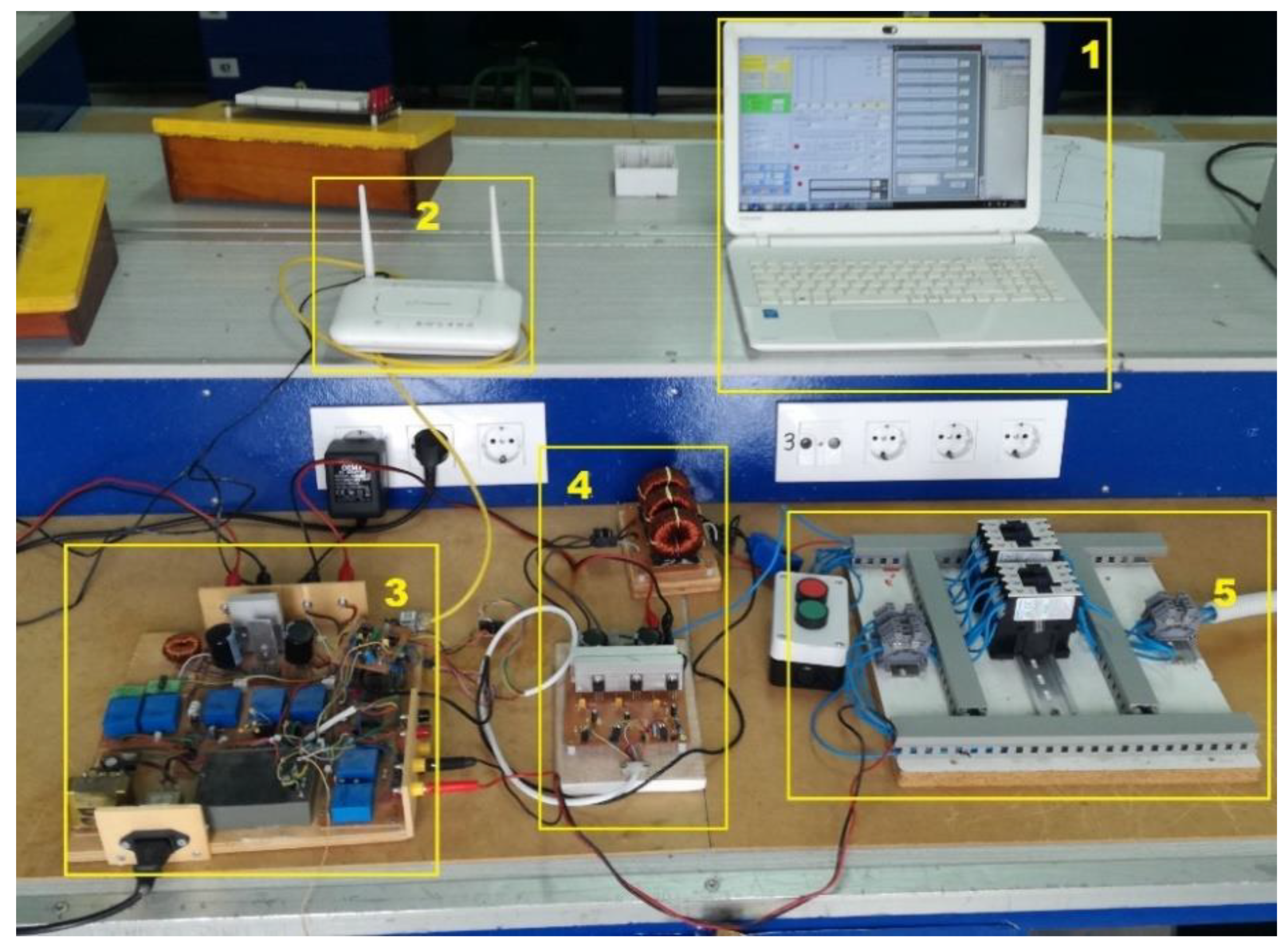
A commercial solar module has been used to generate DC power in the experimental platform. The DC/DC and DC/AC converters has been designed and implemented by the authors. The output of these converter stages has been connected to the laboratory AC electrical system. Figure 7 shows a global vision of the experimental system including some details of the converters boxes. Part number 1 is the PC where all the data are visualized and the control is implemented. Part number 2 is the router responsible for the Wi-Fi communication between the PC and the grid-connected PV system whereas part number 3 and 4 are the DC/DC converter and the DC/AC converter respectively. Finally, part number 5 is the grid connection. The experimental system has been supervised and controlled via wireless.
The DC/DC converter input voltages ranges from 10 V to 70 V whereas 100 V is its maximum output voltage. The power that can be transferred by the buck-boost converter is 70 W. The DC/AC converter has a maximum input voltage and current of 120 V and 4.5 A, respectively. The inverter maximum output voltage is 85 V and it can transfer until 400 W.
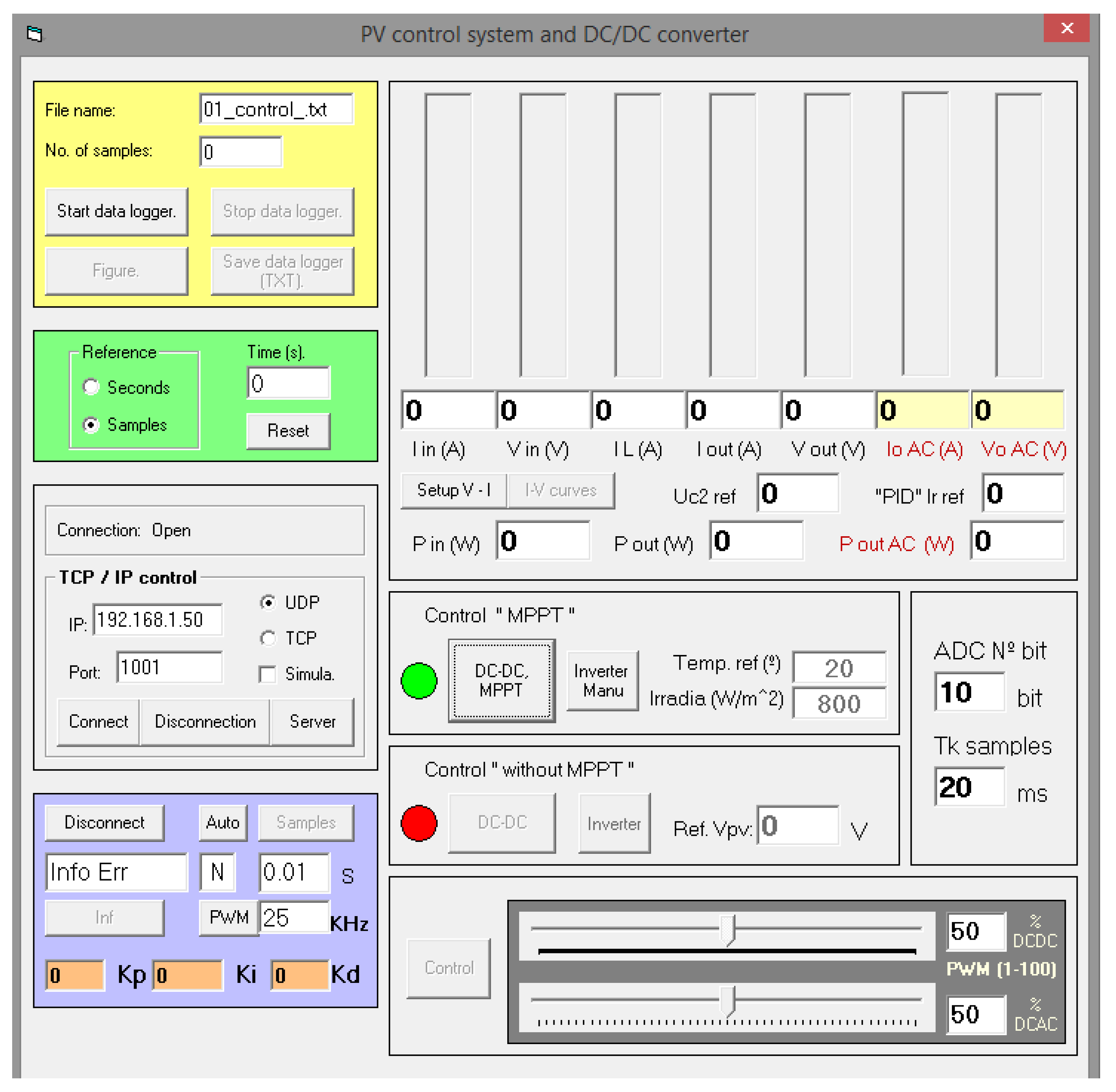
The sensors used to measure the currents and voltages are LEM sensors, LA25-NP and LV25-P respectively. The controller is implemented in a dsPIC30F microcontroller. The temperature is measured with a LM35 sensor and a commercial meter is used for the irradiance. Figure 8 presents a developed virtual instrument, using Visual Basic programming, to supervise the tests.
4.2. Wi-Fi Communication
The communication system is based on point-to-point wireless communication (wireless P2P). To do that, the standard IEEE 802.11 is used. This standard operates in the 2.4 GHz free band and the protocol used to send the data is the User Datagram Protocol—Internet Protocol (UDP-IP). The UDP-IP allows low latency in the transmission because only a simple acknowledgement of message receipt is required. In the case there are some corrupted data, the next sent corrects them since the sampling time is 10 ms and the non-lineal sliding control is robust under perturbations and it allows errors in the data transfer maintaining the system stable.
The grid-connected PV system has sensors connected to a low-cost dsPIC30F4011 microcontroller, which is the responsible for reading the sensors. This dsPIC is connected to a EM203 module. The EM203 is a device that converts the 10/100 Base Ethernet communication of serial communication up to 115.2 kbps and vice versa. The EM203 module sends the signals to the PC, where the controller is implemented and the control signals are calculated. Then, the control signals are sent to the EM203 module to send them to the dsPIC, where the PWM signals are generated.
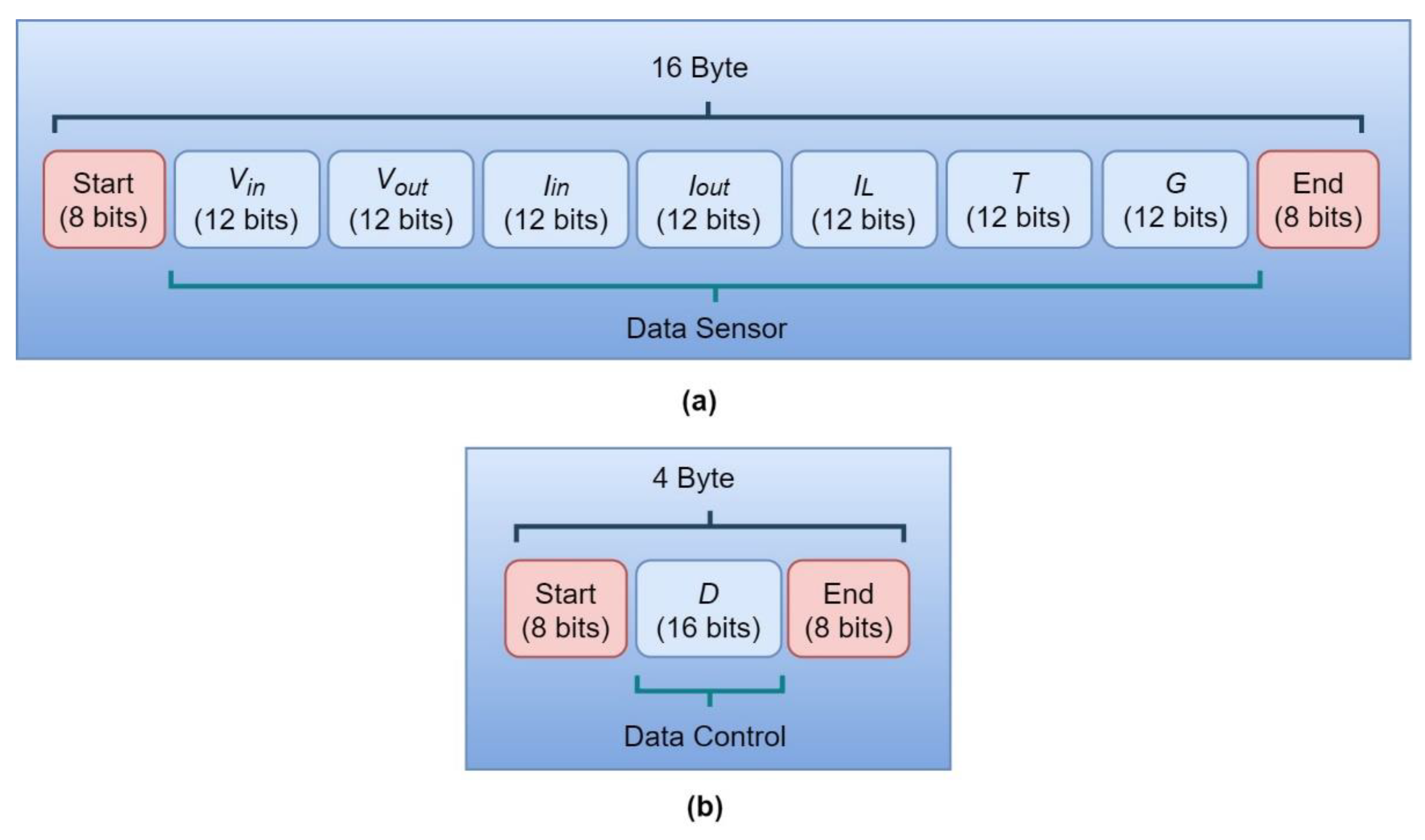
The temperature, irradiance, voltage and current sensors are connected to the dsPIC by means of an ADC port. The ADC has a resolution of 12 bits and it allows a maximum sampling time of 200 ksps. The data from the sensors are sent to the EM203 module by the microcontroller with a frequency of 100 Hz via serial communication port with Tx and Rx signals. Then, the EM203 sends the packet signal, using the UDP-IP protocol, via Wi-Fi to the PC. The serial frame structure and field size sent from the system to the PC is presented in Figure 9. In Figure 9a), a sending from the dsPIC to the PC is depicted. First, a start is sent and then the data from the sensors are sent, the voltages, currents, temperature and irradiance. Finally, the end is sent to notify that the updated data have been sent. The Figure 9b) shows the sending between the PC and the microcontroller. When tha calculations have finished, the control signal is sent. In this work, this signal is sent each 10 ms. The dsPIC receives the signal and generates the PWM regarding the received value. The PWM signal has a resolution of 10 bits and its frequency is 20 kHz.
4.3. Practical Cases
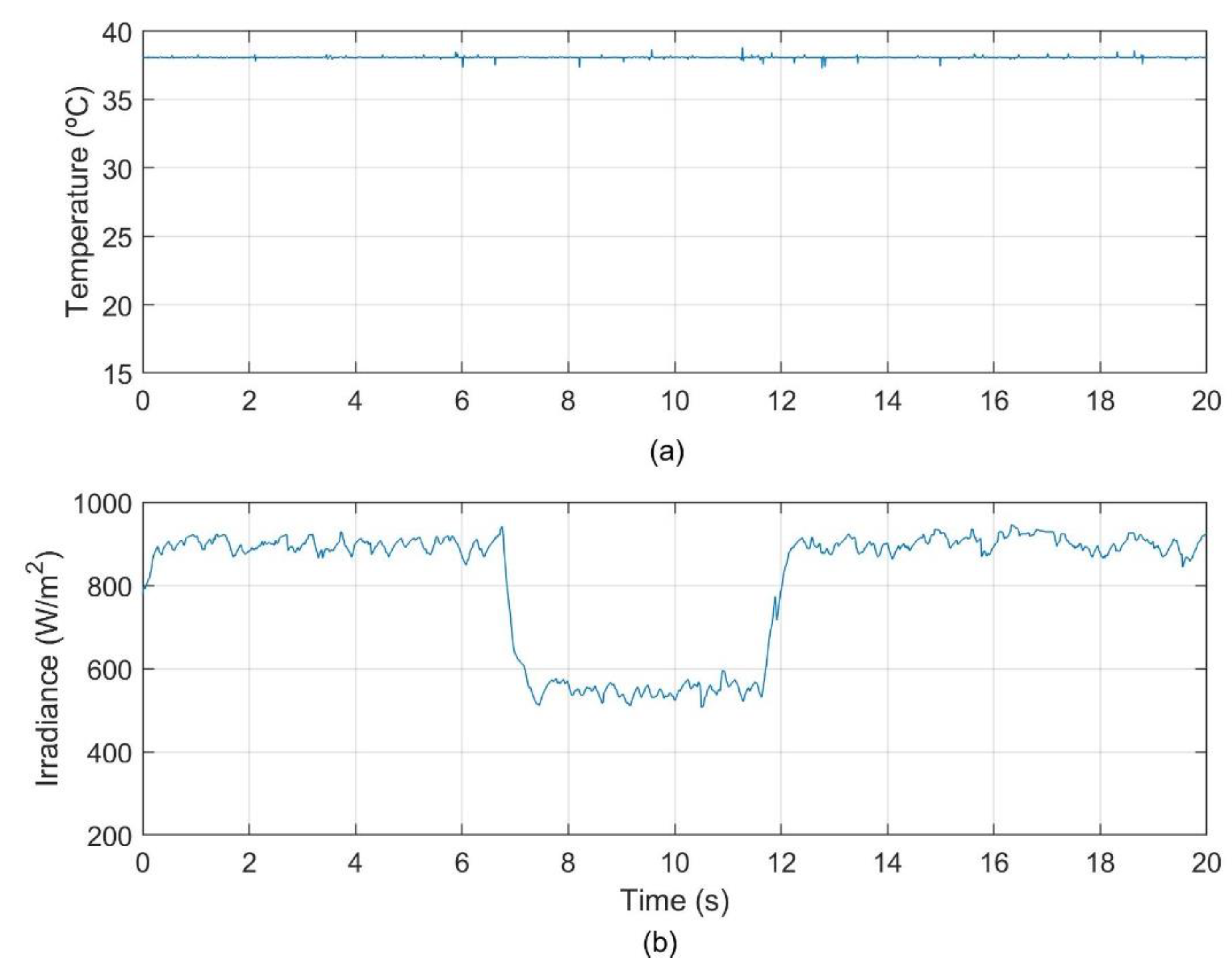
To evaluate the operation of the grid-connected PV system controllers through Wi-Fi, a set of experiments have been carried out. To do that, sudden changes in the irradiance have been considered since it changes from 921 W/m2 to 550 W/m2 at 6.8 s and then it changes again to reach an irradiance of 908 W/m2 at 12.2 s, as Figure 10 shows. It also depicts the temperature that remains almost constant, with a value approximately of 38.2 °C.
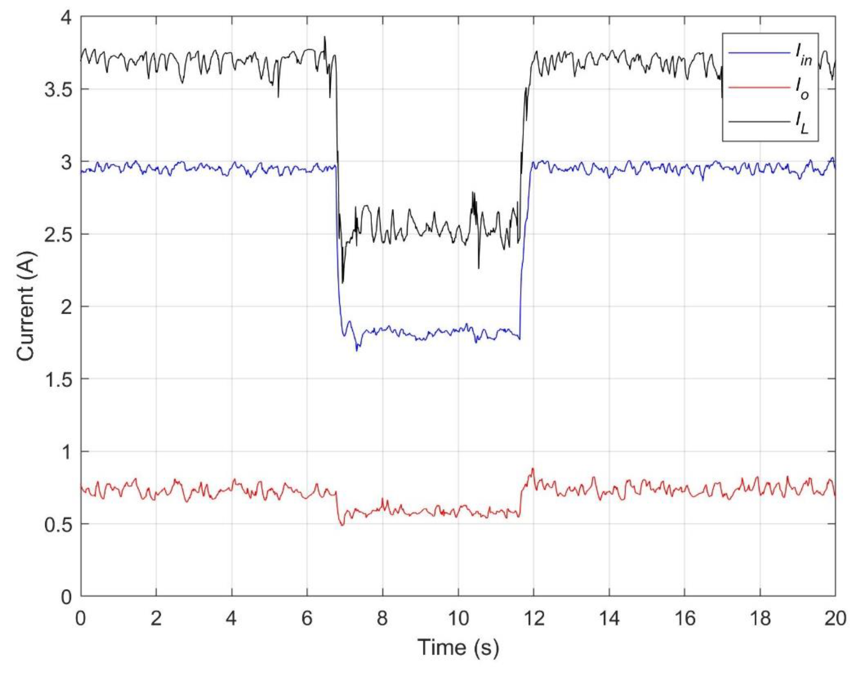
When the changes happen, the other signals are measured and controlled to validate the appropriate operation. Thus, the current at the DC/DC converter input and output are presented in Figure 11. The values of the current vary when the irradiance changes. In this case, due to the location of the MPP, the currents drop when the irradiance decreases its value, and the values of the current rise when the irradiance increases. The signals that are shown are the DC/DC converter input current, the buck-boost converter output current, and the inductor current.
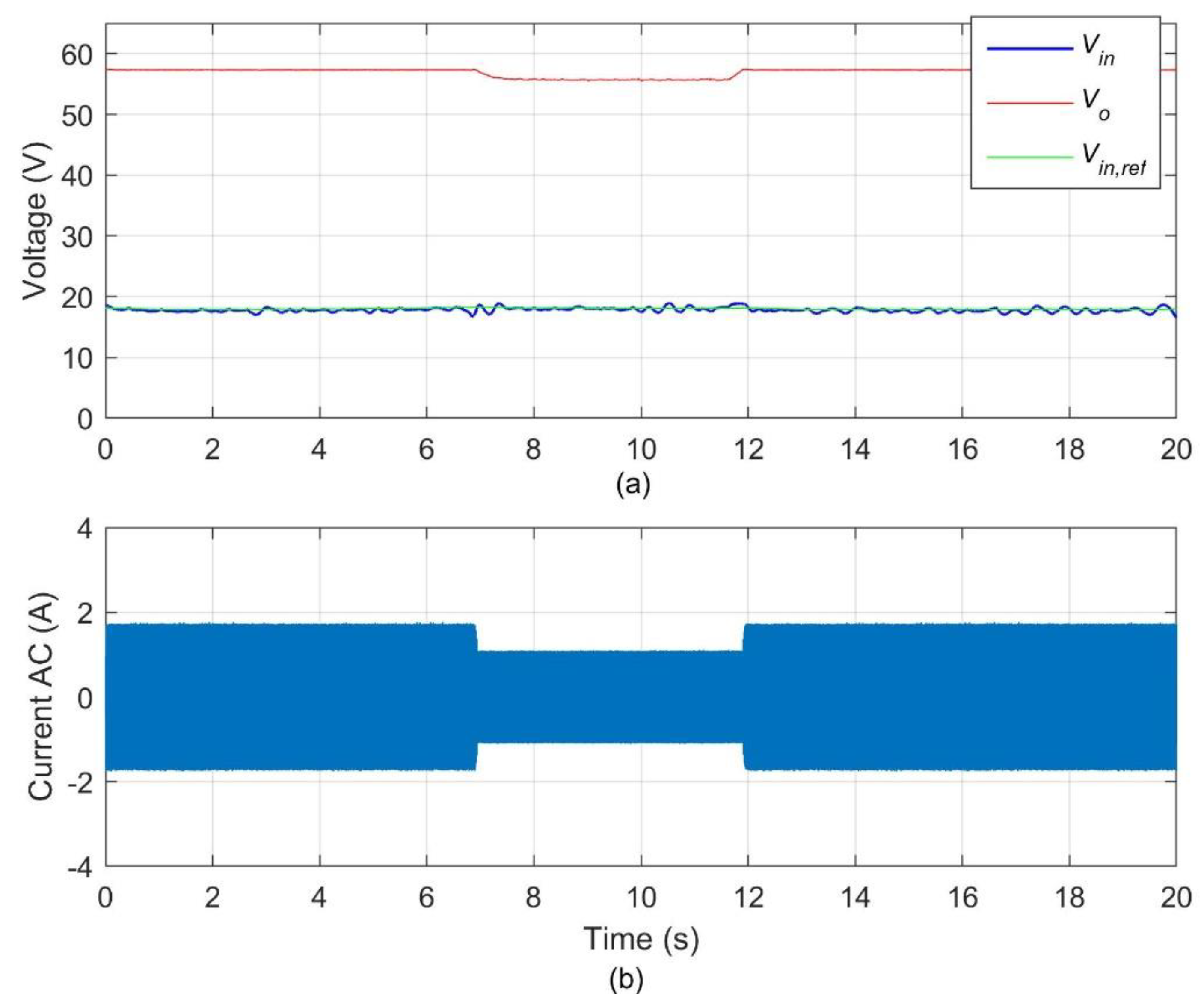
The DC/DC converter output and input voltage and the reference one are depicted in Figure 12. The output voltage decreases when the irradiance is lower and increases when the irradiance is higher. Regarding the input voltage, it tracks the reference voltage with an efficiency of about 99%. In addition, the current at the inverter output is also depicted in this figure and it is a sinusoidal waveform that drops at low irradiance and rises at high irradiance.
The transfer of power is presented in Figure 13, since the input and output power at the DC/DC converter are shown. When the irradiance is higher, the input and output power differ about 1 W (in the first interval of time from 0 to 6.8 s) or 2 W (in the third interval of time from 12.2 s to 20 s) whereas that difference drops to 0.5 W when the irradiance is lower. Thus, the efficiency of the DC/DC converter is calculated, and it has a value that ranges from 9% to 98.4%.
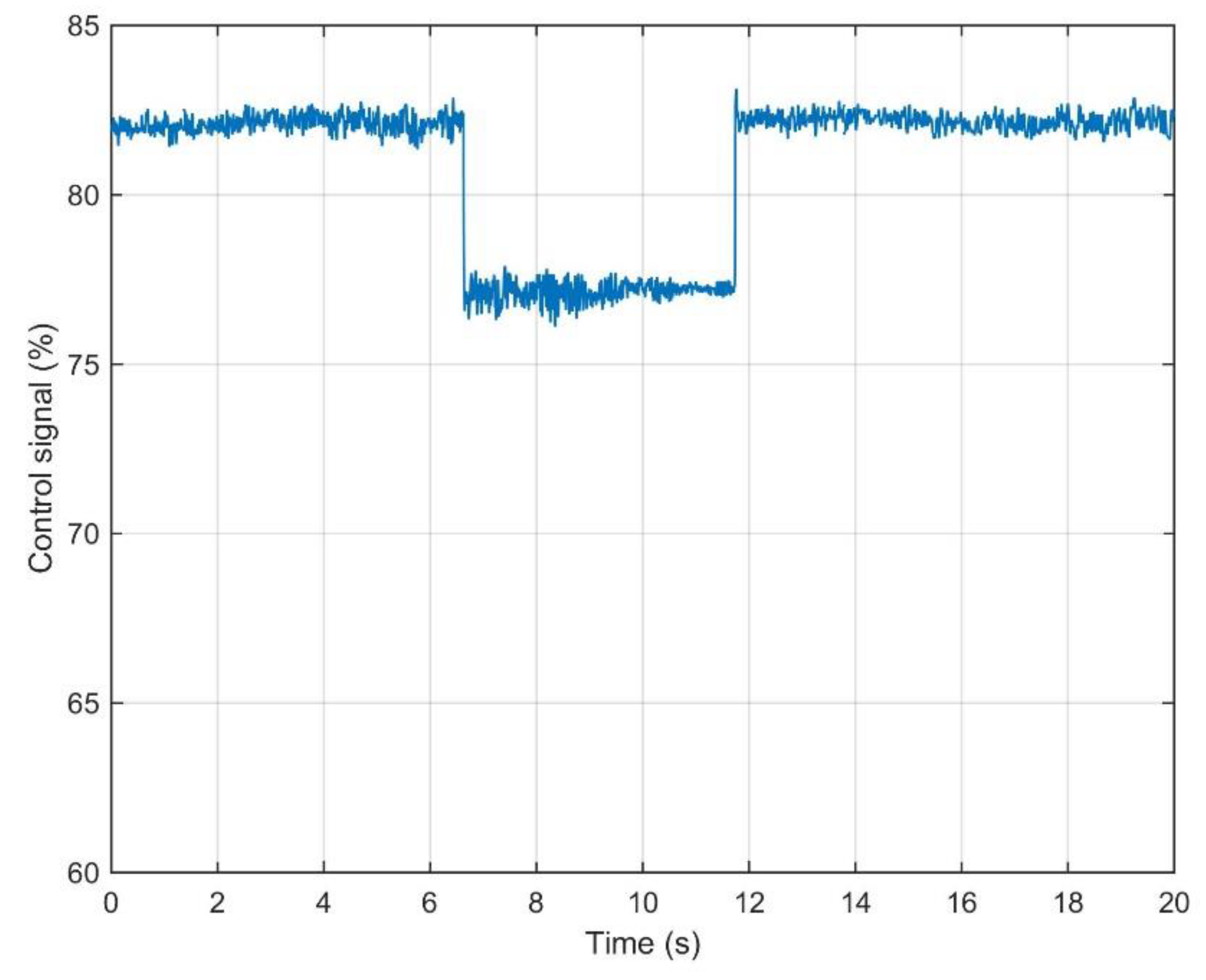
In Figure 14, as with the previous signals, the control signal changes with the irradiance and the discontinuous control effect of the non-lineal controller is also shown. The noise appears due to the wi-fi communication, although it does not affect the correct operation of the system.
Table 1 summarizes the main values of the signals shown in the previous figures. It also presents the rms voltage value, 39 V, and the THD with a value of 1.9%. In addition, the efficiency of the DC/AC converter is presented in the different intervals of time, being the mean value about 94%.
5. Discussion
There are a large variety of controllers to reach the MPP in PV systems. Linear controllers, such as the Perturb and Observe, the Incremental Conductance or the Ripple Correlation Control [16,20], are usually simpler and easier than the non-lineal controllers although they are slower under perturbations and cannot guarantee the stability of the system. Amongst the non-linear controllers, e.g., backstepping, neuro-fuzzy, particle swarm optimization, etc. [19,23], sliding is selected for being a robust control under variations, which it is crucial taking into consideration that wireless data are transferred, causing interferences in the system. Thus, this controller can guarantee stability in the system operation.
Regarding the communication technology, the Wi-Fi is preferred thanks to the advantages, such as low latency, precise data acquisition and the appropriate range. Thus, the Wi-Fi communication can be used in solar plants where the ZigBee technology is not able to transfer data more than 100 m. In addition, the previous works, using ZigBee or Bluetooth communication [10,11,12,13,14,15], are focused on the system monitoring and supervision whereas this work proposed a wireless control besides the monitoring or supervision.
The communication effects have been verified in this work, corroborating that the system is efficient working wireless, as well as by wire, despite the higher level of noise produced wireless. The response of the grid-connected PV system is robust and stable even when there are sudden changes in the parameters or perturbations. Thus, with abrupt changes of the irradiance, the reference voltage is always achieved with an efficiency higher than 99%. The control signal adjusts itself rapidly, even with sudden changes, in 30 ms. The sliding control is also proper for this system taking into account that it is a discontinuous control and operates better than other controls under sudden changes and interferences produced by the wireless technology.
In addition, the dynamic of the system is the appropriate. The references values are always reached, and the efficiency of the DC/DC converter varies between 96% and 98.4% and the DC/AC converter from 92,8% to 94.6%. In addition, in a grid-connected PV system, it is essential not disturb the power quality of the grid. In this case, the THD is low, with a value of only 1.9%. The MPPT efficiency is 99%, proving the validity of the system.
6. Conclusions
In this work, a grid-connected PV system is controlled via wireless. It develops a sliding mode control for the DC/DC converter, that guarantees the achievement of the MPP under all the environmental conditions, and a PI controller for the DC/AC converter, that ensures the power quality requirements of the grid. The use of the Wi-Fi communication allows the system remote control and supervision, with the advantage of reducing costs for the cabling installation. In addition, the wireless communication allows the operation of the system in real-time, facilitating the detection of faults rapidly. The advantage of the Wi-Fi technology is the precision of the acquired data and low latency, guaranteeing robustness. The system has been validated in an experimental platform and the results show the optimum performance of the whole system.
Author Contributions
Conceptualization, A.D.M. and J.M.C.; formal analysis, A.D.M. and J.M.C.; investigation, A.D.M., J.M.C., R.S.H., and J.R.V.; methodology, A.D.M. and J.M.C.; project administration, R.S.H., J.R.V., and F.J.R.-R.; resources, R.S.H., J.R.V., and F.J.R.-R.; validation, A.D.M. and J.M.C.; writing—original draft, A.D.M.; writing—review & editing, A.D.M., J.M.C., R.S.H., J.R.V., and F.J.R.-R. All authors have read and agreed to the published version of the manuscript.
Funding
This research received no external funding.
Conflicts of Interest
The authors declare no conflict of interest.
References
- Shin, J.H.; Kim, J.O. On-line diagnosis and fault state classification method of photovoltaic Plant. Energy 2020, 13, 4584. [Google Scholar] [CrossRef]
- Chen, Z.; Wu, L.; Cheng, S.; Lin, P.; Wu, Y.; Lin, W. Intelligent fault diagnosis of photovoltaic arrays based on optimized kernel extreme learning machine and I-V characteristics. Appl. Energy 2017, 204, 912–931. [Google Scholar] [CrossRef]
- Chena, Z.; Chena, Y.; Wua, L.; Chenga, S.; Lin, P. Deep residual network based fault detection and diagnosis of photovoltaic arrays using current-voltage curves and ambient conditions. Energy Convers. Manag. 2019, 198, 111793. [Google Scholar] [CrossRef]
- Zhao, Q.; Shao, S.; Lu, L.; Liu, X.; Zhu, H. A new PV array fault diagnosis method using fuzzy c-mean clustering and fuzzy membership algorithm. Energy 2018, 11, 238. [Google Scholar] [CrossRef] [Green Version]
- Sun, X.; Chavali, R.V.K.; Alam, M.A. Real-time monitoring and diagnosis of photovoltaic system degradation only using maximum power point-the Suns-Vmp method. Prog. Photovolt. 2018, 27, 55–66. [Google Scholar] [CrossRef] [Green Version]
- Samara, S.; Natsheh, E. Intelligent PV panels fault diagnosis method based on NARX network and linguistic fuzzy rule-based systems. Sustainability 2020, 12, 2011. [Google Scholar] [CrossRef] [Green Version]
- Rivai, A.; Rahim, N.A.; Elias, M.F.M.; Jamaludin, J. Analysis of photovoltaic string failure and health monitoring with module fault identification. Energy 2020, 13, 100. [Google Scholar] [CrossRef] [Green Version]
- Silvestre, S.; Mora-López, L.L.; Kichoua, S.; Sánchez-Pacheco, F.; Domínguez-Pumar, M. Remote supervision and fault detection on OPC monitored PV systems. Solar Energy 2016, 137, 424–433. [Google Scholar] [CrossRef] [Green Version]
- Chao, K.H.; Chen, C.T. A remote supervision fault diagnosis meter for photovoltaic power generation systems. Measurment 2017, 104, 93–104. [Google Scholar] [CrossRef]
- Krauter, S.C.W.; Depping, T. Remote PV-system monitored via satellite Solar Energy Materials and Solar Cells. Solar Energy Mater. Sol. Cells 2004, 82, 139–150. [Google Scholar] [CrossRef]
- Gagliarducci, M.; Lampasi, D.A.; Podestà, L. GSM-based monitoring and control of photovoltaic power generation. Measurment 2007, 40, 314–321. [Google Scholar] [CrossRef]
- Lopez-Vargas, A.; Fuentes, M.; Vivar, M. IoT application for real-time monitoring of solar home systems based on arduinoTM with 3G connectivity. IEEE Sens. J. 2019, 19, 679–691. [Google Scholar] [CrossRef]
- Papadakis, K.; Koutroulis, E.; Kalaitzakis, K. A server database system for remote monitoring and operational evaluation of renewable energy sources plants. Renew. Energy 2005, 30, 1649–1669. [Google Scholar] [CrossRef]
- Xia, K.; Ni, J.; Ye, Y.; Xu, P.; Wang, Y. A real-time monitoring system based on ZigBee and 4G communications for photovoltaic generation. CSEE J. Power Energy Syst. 2020, 6, 52–63. [Google Scholar]
- Moon, S.; Kim, S.J.; Seo, J.W.; Park, J.H.; Park, C.; Chung, C.S. Maximum power point tracking without current sensor for photovoltaic module integrated converter using Zigbee wireless network. Electr. Power Energy Syst. 2014, 56, 286–297. [Google Scholar] [CrossRef]
- Subudhi, B.; Pradhan, R. A comparative study on maximum power point tracking techniques for photovoltaic power systems. IEEE Trans. Sustain. Energy 2013, 4, 89–98. [Google Scholar] [CrossRef]
- Martín, A.D.; Cano, J.M.; Herrera, R.S.; Vazquez, J.R. Wireless sliding MPPT control of photovoltaic systems in distributed generation systems. Energies 2019, 12, 3226. [Google Scholar] [CrossRef] [Green Version]
- Koca, Y.B.; Aslan, Y.; Oguz, Y. Boost Converter Design and Analysis for Photovoltaic Systems. In Proceedings of the International Conference on Engineering Technology and Applied Sciences, ICETAS, Kiev, Ukraine, 24–28 April 2019. [Google Scholar]
- Martin, A.D.; Cano, J.M.; Silva, J.F.A.; Vazquez, J.R. Backstepping control of smart grid-connected distributed photovoltaic power supplies for telecom equipment. IEEE Trans. Energy Convers. 2015, 30, 1496–1504. [Google Scholar] [CrossRef]
- Shazly, A.M.; Montaser, A.E.S. A comparative study of P&O and INC maximum power point tracking techniques for grid-connected PV systems. SN Appl. Sci. 2019, 1, 174. [Google Scholar]
- Rezk, H.; Aly, M.; Al-Dhaifallah, M.; Shovama, M. Design and Hardware Implementation of New Adaptive Fuzzy Logic-Based MPPT Control Method for Photovoltaic Applications. IEEE Access 2019, 8, 106427–106438. [Google Scholar] [CrossRef]
- Zecevic, Z.; Rolevski, M. Neural network approach to MPPT control and irradiance estimation. Appl. Sci. 2020, 10, 5051. [Google Scholar] [CrossRef]
- Hu, K.; Cao, S.; Li, W.; Zhu, F. An Improved Particle Swarm Optimization Algorithm Suitable for Photovoltaic Power Tracking Under Partial Shading Conditions. IEEE Access 2019, 7, 143217–143232. [Google Scholar] [CrossRef]
- Lyden, S.; Haque, M.E. Maximum power point tracking techniques for photovoltaic systems: A comprehensive review and comparative analysis. Renew. Sustain. Energy Rev. 2015, 52, 1504–1518. [Google Scholar] [CrossRef]
- Brito, M.A.G.; Galotto, L.; Sampaio, L.P.; Melo, G.A.; Canesin, C.A. Evaluation of the main MPPT techniques for photovoltaic applications. IEEE Trans. Ind. Electron. 2013, 60, 1156–1167. [Google Scholar] [CrossRef]
- Dahech, K.; Allouche, M.; Damak, T.; Tadeo, F. Backstepping sliding mode control for maximum power point tracking of a photovoltaic system. Electr. Power Syst. Res. 2017, 143, 182–188. [Google Scholar] [CrossRef]
- Hariri, M.H.M.; Desa, M.K.M.; Masri, S.; Zainuri, M.A.A.M. Grid-Connected PV generation system–components and challenges: A review. Energies 2020, 13, 4279. [Google Scholar] [CrossRef]
- Kadir, A.F.A.; Khatib, T.; Elmenreich, W. Integrating photovoltaic systems in power system: Power quality impacts and optimal planning challenges. Int. J. Photoenergy 2014, 2014, 321826. [Google Scholar]
- Bellinaso, L.V.; Figueira, H.H.; Basquera, M.F.; Vieira, R.P.; Grundling, H.A.; Michels, L. Cascade Control with adaptive voltage controller applied to photovoltaic boost converters. IEEE Trans. Ind. Appl. 2019, 55, 1903–1912. [Google Scholar] [CrossRef]
- Errouissi, R.; Muyeen, S.M.; Al-Durra, A.; Leng, S. Experimental validation of a robust continuous nonlinear model predictive control based grid-interlinked photovoltaic inverter. IEEE Trans. Ind. Electron. 2016, 63, 4495–4505. [Google Scholar] [CrossRef] [Green Version]
- Errouissi, R.; Al-Durra, A.; Muyeen, S.M. Design and implementation of a nonlinear PI predictive controller for a grid-tied photovoltaic inverter. IEEE Trans. Ind. Electron. 2017, 64, 1241–1250. [Google Scholar] [CrossRef] [Green Version]
- Hannan, M.A.; Ghani, Z.A.B.D.; Hoque, M.M.; Ker, P.J.; Hussain, A.; Mohamed, A. fuzzy logic inverter controller in photovoltaic applications: Issues and recommendations. IEEE Access 2017, 7, 24934–24955. [Google Scholar] [CrossRef]
Figure 1.
Structure of the system.

Figure 2.
I-V and P-V characteristic curves of a PV module.

Figure 3.
Buck-boost converter connected between PV array and the load.

Figure 4.
DC/DC converter input and output voltages for some D values.

Figure 5.
Topology of the inverter.

Figure 6.
PI current control scheme.

Figure 7.
Experimental platform.

Figure 8.
Screen of the designed virtual instrument.

Figure 9.
Serial frame structure and field size: (a) sending from the dsPIC to the PC; (b) sending of the control signals from the PC to the dsPIC.
Figure 9.
Serial frame structure and field size: (a) sending from the dsPIC to the PC; (b) sending of the control signals from the PC to the dsPIC.

Figure 10.
Evolution of the environmental conditions: (a) temperature; (b) irradiance.

Figure 11.
Evolution of the current at the DC/DC converter.

Figure 12.
Voltage and current evolution: (a) voltage signals at the DC/DC converter and reference voltage; (b) AC current.
Figure 12.
Voltage and current evolution: (a) voltage signals at the DC/DC converter and reference voltage; (b) AC current.

Figure 13.
DC/DC converter power.

Figure 14.
Control signal evolution.


Table 1.
Summary of the values of the experimental case.
| Time (s) | (0–6.8) | (6.8–12.2) | (12.2–20) |
|---|---|---|---|
| DC/DC Converter | |||
| G (W/m2) | 921 | 550 | 908 |
| Vin (V) | 17.9 | 18.2 | 17.88 |
| Iin (A) | 2.9 | 1.82 | 2.97 |
| Pin (W) | 51.91 | 33.12 | 53.1 |
| Vo (V) | 56.5 | 55.85 | 56.01 |
| Io (A) | 0.9 | 0.57 | 0.91 |
| Po (W) | 50.85 | 32.12 | 50.97 |
| Efficiency | 0.96 | 0.97 | 0.96 |
| DC/AC Converter | |||
| Igrid | 1.71 | 1.08 | 1.71 |
| Irms,grid | 1.21 | 0.77 | 1.21 |
| Vrms | 39 | ||
| THD | 1.9 | ||
| Prms | 47.21 | 30.35 | 47.24 |
| Efficiency | 0.935 | 0.946 | 0.928 |
Publisher’s Note: MDPI stays neutral with regard to jurisdictional claims in published maps and institutional affiliations. |
© 2021 by the authors. Licensee MDPI, Basel, Switzerland. This article is an open access article distributed under the terms and conditions of the Creative Commons Attribution (CC BY) license (https://creativecommons.org/licenses/by/4.0/).
Share and Cite
MDPI and ACS Style
Cano, J.M.; Martin, A.D.; Herrera, R.S.; Vazquez, J.R.; Ruiz-Rodriguez, F.J. Grid-Connected PV Systems Controlled by Sliding via Wireless Communication. Energies 2021, 14, 1931. https://doi.org/10.3390/en14071931
AMA Style
Cano JM, Martin AD, Herrera RS, Vazquez JR, Ruiz-Rodriguez FJ. Grid-Connected PV Systems Controlled by Sliding via Wireless Communication. Energies. 2021; 14(7):1931. https://doi.org/10.3390/en14071931
Chicago/Turabian StyleCano, Juan M., Aranzazu D. Martin, Reyes S. Herrera, Jesus R. Vazquez, and Francisco Javier Ruiz-Rodriguez. 2021. "Grid-Connected PV Systems Controlled by Sliding via Wireless Communication" Energies 14, no. 7: 1931. https://doi.org/10.3390/en14071931
Note that from the first issue of 2016, this journal uses article numbers instead of page numbers. See further details here.