
Magnetic Field Energy Harvesting with a Lead-Free Piezoelectric High Energy Conversion Material

Department of Electrical Engineering, Hanyang University, Seoul 133-791, Korea
*
Author to whom correspondence should be addressed.
†
These authors contributed equally to this work.
Energies 2021, 14(5), 1346; https://doi.org/10.3390/en14051346
Submission received: 18 January 2021
/
Revised: 21 February 2021
/
Accepted: 23 February 2021
/
Published: 2 March 2021
(This article belongs to the Section D1: Advanced Energy Materials)
Abstract
:This article presents a high-performance lead-free piezoelectric energy harvester (LPEH) system for magnetic field. It based on a Ba0.85Ca0.15Ti0.90Zr0.10O3 + CuO 0.3 wt% (BCTZC0.3) composite was fabricated by sintering at 1450 °C. The BCTZC0.3 composite, which has an enhanced high energy conversion constant (), shows improved piezoelectric power-generation performance when compared with conventional piezoelectric energy harvesters. The BCTZC0.3-based LPEH produces instantaneous maximum power of 8.2 mW and an energy density of 107.9 mW/cm3 in a weak magnetic field of 250 μT. This system can be used to charge a capacitor and operate a wireless sensor network (WSN) system to provide temperature sensing and radio-frequency (RF) transmission in a 250 μT magnetic field. The proposed LPEH is a promising green-energy device for potentially self-powering WSN systems when applied.
1. Introduction
Self-driven energy harvesting technology, which concerns the gathering of energy from the environment, is attracting considerable research interest. Piezoelectric, electrothermal, triboelectric, and electromagnetic induction technologies are the main research areas in this field at present [1]. The power of energy harvesting technologies has been demonstrated by their role in providing large amounts of energy for the operation of wireless sensor networks (WSNs). Traditional use of commercial batteries has become unsuitable and impractical for applications such as WSNs, since their limited battery lifecycles and potential as environmental hazards become problems [2]. In contrast, piezoelectric energy harvesting offers high power-density levels and has a wide range of potential applications in the field [3]. A magnetic field represents an energy source that can be used in energy harvesting, with one example being that it can be used to generate vibrations. Electronic devices, power cables, and the magnetic fields generated by them have a frequency of 60 Hz. However, it is difficult to harvest an electrical source from weak magnetic fields [4,5,6]. Piezoelectric materials generate electricity when they are subjected to vibration stress [7]. A permanent magnet can be used as a tip mass at the end of a cantilever and vibrations can be generated by a magnetic field, even in an energy harvester, in almost negligible magnetic fields [8,9]. Under these conditions, it will be necessary to improve the efficiency of piezoelectric materials to improve their energy-harvesting properties, particularly in low magnetic fields. Piezoelectric energy harvesting technology development will require material optimization efforts, including the development of high-quality piezoelectric compositions, mechanical optimization to enable more efficient conversion of the energy from the surrounding environment, and electrical optimization efforts to apply high-efficiency electric circuit techniques to maximize the power transfer [10,11]. This will require a technical field that has fusion research involving both the mechanical and electrical spheres. Xing et al., were first proposed a multimode harvesting device based on a piezoelectric cantilever and a permanent magnet tip mass. At the time, this type of design was proven to have good performance at low frequencies. After that, Liu et al., designed a bimorph piezoelectric cantilever structure with PZT and NdFeB magnets, which obtained a maximum power density of 11.73 μW/cm3 for resonance excitations at 100 Hz and 100 μT [12,13,14]. However, this level of performance is still difficult to put into commercial applications, faced with this challenge, this paper carried out a higher performance energy harvester research. The aim of the study presented here is therefore to develop a piezoelectric energy harvester that is capable of high power generation owing to its enhanced energy conversion constant [15,16]. In general, cantilever-type piezoelectric energy harvesters use bending vibration modes for electromechanical energy conversion. To improve the performance of a piezoelectric harvester that gathers electrical energy from ambient vibrations, it will be essential to improve the piezoelectric energy-conversion constant through material optimization [17,18]. The high energy density of this type of piezoelectric material can be expressed using Equation (1), as follows.
The performance of piezoelectric ceramics can be expressed using the energy conversion coefficient , which is obtained by multiplying the piezoelectric charge factor () by the piezoelectric voltage factor () in a manner identical to that used in energy-harvesting equations. This coefficient is an important performance index in many applications. To improve the performance of the piezoelectric energy harvester, a material composition with a high energy conversion constant must be developed [19,20]. In a mechanical optimization process, we designed and manufactured a piezoelectric harvester with a high-output structure that is suitable for specific applications via multiphysics analysis [21,22]. In the electrical optimization process, we attempted to maximize the power density of this harvester using an impedance-matching technique, which is a type of maximum power transfer circuit technique [23,24]. To improve both the piezoelectric and dielectric properties of the materials, solid solutions are used at both the A and B sites of BaTiO3 (in general, A = Ca, Sr, and La, and B = Nb, Ta, and Zr) [25,26]. In particular, Ca2+ and Zr4+ doping has reportedly provided high piezoelectric coefficients ( = 620 pC/N) for Ba0.85Ca0.15Ti0.90Zr0.10O3 (BCTZ) [27]. Most studies have focused on control of the sintering temperature of the material and the roles of dopant and ion substitution to produce increases in the piezoelectric charge coefficient (d) when using the same composition, although this is accompanied by changes in the BCTZ microstructure [28,29]. To develop a lead-free piezoelectric composition, the acceptor dopant ion Cu2+ is typically used to improve the output characteristics of piezoelectric materials and to reduce their sintering temperatures [30,31]. As a sintering aid, CuO can reduce sintering temperatures effectively, and it is also well known to improve the dense microstructure of these piezoelectric materials.
Thereout, we propose a high-performance lead-free piezoelectric energy harvester (LPEH) device based on a lead-free Ba0.85Ca0.15Ti0.90Zr0.10O3 + CuO 0.3 wt% (BCTZC0.3) system. The LPEH fabricated in this work produces a high open-circuit voltage of approximately 104 V and instantaneous output power of 8.2 mW (power density: 107.9 mW/cm3) with a load resistance of 10 kΩ during periodic motion changes that involve bending and unbending in a 250 μT magnetic field. This LPEH device was connected to a capacitor to form power modules for use in self-powered systems under power-line cables. Furthermore, the power generated by a 250 μT magnetic field is enough to operate a commercial WSN system. This achievement is unprecedented with regards to optimization of composite-based energy harvesters and represents an initial approach towards the use of lead-free piezoelectric composites in these devices.
2. Experimental
Fabrication of a lead-free piezoelectric ceramic material: the lead-free BCTZC0.3 ceramic was produced using a conventional solid-state reaction method. The powders used were weighed. BaCO3 (99.0%, CAS No.513-77-9, Daejung, Korea), CaCO3 (99.0%, Lot No. 2018A1662, JUNSEI, Japan), TiO2 (99.0%, Lot No. 2018B1266, JUNSEI, Japan), ZrO3 (99.0%, CAS No.1314-23-4, Daejung, Korea), and CuO (99.9%), were mixed via ball milling in alcohol for 24 h. After drying, the mixture was calcined in an alumina crucible at 1250 °C for 2 h. The calcined powder was then milled for another 12 h. The dried powder was subsequently mixed with 2% polyvinyl alcohol (PVA) and made into a bulk disk form at a pressure of 100 MPa. The green disk was then sintered in air at 1300–1450 °C for 2 h and the sintered bulk surface was subsequently polished before the measurements were performed. The calcined powder was again mixed with a plasticizer (B-73225, FERRO, USA) and polyvinyl butyral resin (PVB) as a polymer for 24 h to prepare a slurry with a ceramic-to-polymer relative weight ratio of 2:1. The slurry was then deformed in a vacuum for 30 min to remove any bubbles. A green sheet with a thickness of approximately 30 μm was prepared using the finished slurry via a tape casting process. A square sample with dimensions of 30 × 40 mm2 was prepared using a cutter (DC-5, DH) and the sheets were laminated on a layer-by-layer basis. In total, ten green sheets were laminated for 10 min at 60 °C under a pressure of 10 kg in each case. To remove the organic additives from the laminated sheet, the specimens were heated slowly to 600 °C and held at that temperature for 3 h in an electric furnace (AJ-MLBF2, AJEON). To allow the film to undergo poling, an electric field was applied to the sintered thick film for 2 h at 2 kV/mm.
Characterization of the lead-free piezoelectric ceramic material: field emission-scanning electron microscope (FE-SEM) imaging and an energy dispersive spectroscopy (EDS) mapping analysis were performed using a Verios 460L SEM. The crystalline phase and orientation were analyzed via high-resolution X-ray diffraction (XRD) (HR-XRD; ATX-G, Rigaku Co.) and X-ray photoelectron spectroscopy (XPS) spectroscopy (Invia Raman Microscope, Renishaw) measurements. The piezoelectric charge constant was measured using a meter (PM100, Piezotest), and the piezoelectric and dielectric properties were determined using an impedance analyzer (HP4194A Hewlett Packard) using IEEE standards.
Measurement of energy-harvesting properties: The BCTZC0.3 films were attached to the top of a stainless-steel substrate (SUS304) and were tested using an oscilloscope (Tektronix, DPO4054B) to evaluate their power-generation characteristics with a shaker (Brűel & Kjær, 4809) and a high-speed bipolar amplifier (NF, HSA4014). The amplifier was driven by a function generator (Agilent, 33220A) and the shaker provided periodic excitation with a harmonic signal. To produce a magnetic field on the LPEH, an AC magnetic field was applied to the harvesters using a Helmholtz coil. The harvesters in the magnetic field were measured in a frequency range of 30 to 90 Hz using a function generator (Agilent, 33220A). The samples were collected as a function of the applied DC magnetic field from 0–250 μT using a high-speed bipolar amplifier (NF, HSA4014) in a fixed AC magnetic field at 60 Hz (their resonance frequency). Energy harvesting through the fabricated LPEH was demonstrated around the power-line cable of an automatic voltage regulator (30 kV, 60 Hz), which was used as the magnetic field source.
3. Results and Discussion
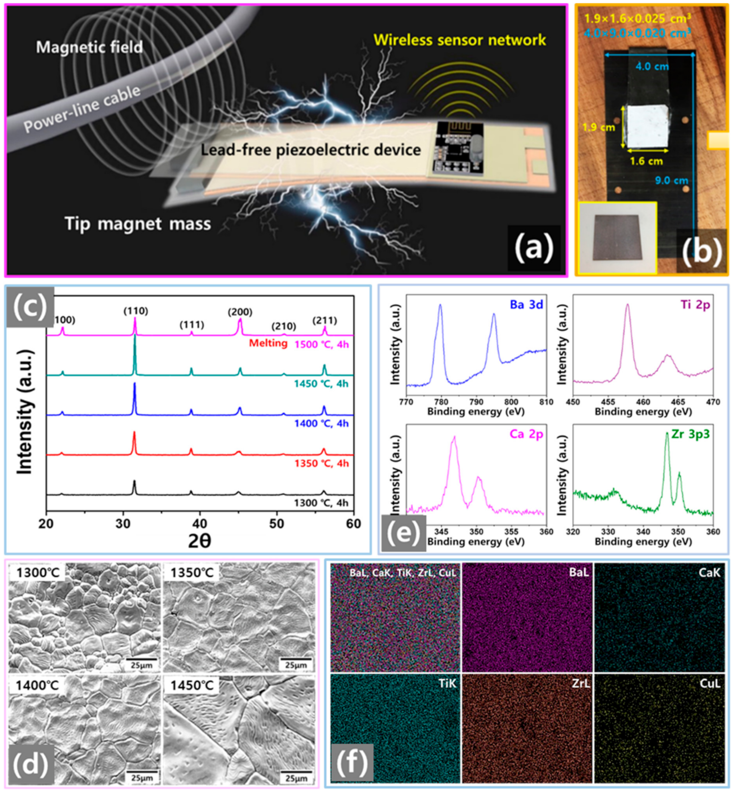
To demonstrate a high energy conversion device, BCTZC0.3-based lead-free piezoelectric ceramic comparable to the PZT-based piezoelectric ceramic served as an active material. For the magnetic field phase, a magnetic metal was used as the tip mass. A magnetic tip mass is advantageous for promoting improved energy-harvesting performance in a weak AC magnetic field, and the BCTZC0.3 film composite fabricated on a spring-metal substrate had achieved a high output voltage coefficient in previous work. The LPEH consisted of a high energy conversion material and a magnetic tip mass, as shown in Figure 1a. The high energy conversion property of the LPEH in a weak magnetic field range contributed to improved energy harvesting performance by the composite. The magnetoelectric effect in the LPEH results in the conversion of the magnetic field to mechanical strain, which is then converted to an electric charge through the lead-free BCTZC0.3. To realize a magnetoelectric harvester operating at 60 Hz, the piezoelectric energy material (1.9 × 1.6 × 0.25 cm3) was attached to a spring-metal substrate (4.0 × 9.0 × 0.02 cm3) as the LPEH, as shown in Figure 1b. The inset indicates the piezoelectric active material when sintered at 1450 °C. The energy-harvesting performance contribution of the sintering temperature on the LPEH is demonstrated in Figure 3i. In order to improve the lead-free piezoelectric energy-harvesting performance in a weak magnetic field, the energy conversion of the LPEH was increased by changing the sintering temperature. To design the optimum piezoelectric energy-harvesting composition, BCTZC0.3 ceramics with improved power conversion constant values were fabricated. These BCTZC0.3 samples were sintered at various temperatures ranging from 1300 to 1450 °C. Figure 1c shows the results of an X-ray diffraction (XRD) analysis of the sintering temperatures that were utilized to investigate the optimum composition of the BCTZC0.3 samples. Rhombohedral crystals with a perovskite structure and without a secondary phase were observed for the BCTZC0.3 depending on the sintering temperature. As the sintering temperature was increased from 1300 to 1450 °C, the (110) peak intensity also showed a comparative increase. This outcome is closely related to the increase in grain size, as observed in the field emission-scanning electron microscope (FE-SEM) images indicated in Figure 1d. For the BCTZC0.3 sample that was sintered at 1500 °C, even if the (200) intensity increased, the (110) intensity decreased. This was observed as the melting phenomenon progressed. Figure 1d shows surface images of the BCTZC0.3 samples with changes in the sintering temperatures. The BCTZC0.3 samples that were sintered at 1350 °C show various grain sizes ranging from 5 to 10 μm, and these grains grew from 20 μm to more than 100 μm. Hence, the grain size increased considerably when the sintering temperature was increased to 1450 °C. With the sample sintered at 1500 °C, the surfaces melted due to the high sintering temperature and the piezoelectric and dielectric properties could not be measured (see Supporting Information Figures S3–S5). Figure 1e shows the results of an X-ray photoelectron spectroscopy (XPS) analysis of the BCTZC0.3 sample sintered at 1450 °C. Ba, Ti, Ca, and Zr components were detected, whereas no secondary phase corresponding to CuO was detected. Furthermore, the Ba, Ca, Ti, Zr, and Cu atoms were homogeneously dispersed on the surface of the BCTZC0.3 sample, as in the energy dispersive spectrometer (EDS) mapping images in Figure 1f.
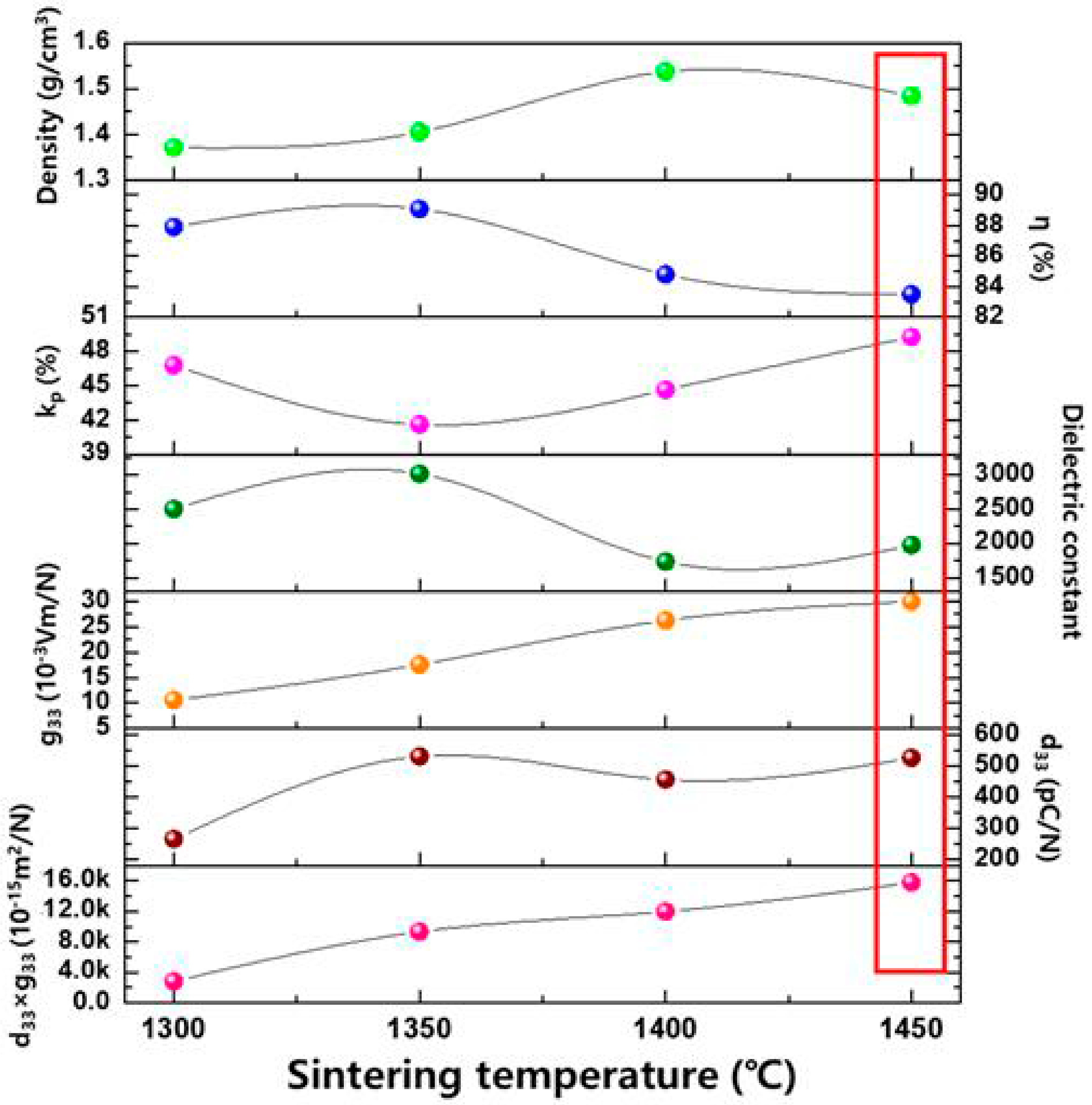
Figure 2 shows the piezoelectric and dielectric properties of the BCTZC0.3 samples with respect to the sintering temperature used. As the sintering temperature was increased, the material density generally increased in all BCTZC0.3 samples. The conversion efficiency exceeded 82% in all sintered samples. As the sintering temperature was increased, the conversion constant also generally increased, but the value of the quality factor decreased. The piezoelectric voltage constant also showed an improvement, caused by the increases in both the piezoelectric charge constant () and the relative dielectric constant. The piezoelectric voltage constant can be determined using the equation . The dielectric constant tends to decrease as the sintering temperature increases to more than 1400 °C, which then leads to an improvement in the piezoelectric voltage constant. Because this piezoelectric voltage constant improved, the BCTZC0.3 sample that was sintered at 1450 °C had a high power-conversion constant. This phenomenon is related to both the grain growth and the increased intensity of the (110)-oriented crystal. Table 1 presents the values of the piezoelectric and dielectric characteristics of the samples based on various sintering temperatures. The BCTZC0.3 specimen sintered at 1450 °C has a high piezoelectric charge constant () of 526 pC/N, a conversion constant of 49.3%, and a high power conversion constant of 15,780 × 10−15 m2/N. Therefore, we used the BCTZC0.3 sample sintered at 1450 °C as the active material of the LPEH.
Table 2 shows the output signals from the LPEH and other previously reported piezoelectric energy harvesters, along with values pertaining to the acceleration (m/s2), resonance frequencies (Hz), and energy-conversion constants of these harvesters. Among the PZT series devices the energy-conversion constant is 9.3 k when using bulk PZT-5A, and the corresponding output power and power density are 40 μW and 0.38 μW/mm3, respectively. The maximum output power was observed when using the PZT-CN material, which had a high piezoelectric conversion constant of 14 k, a maximum output power of 17,300 μW, and power density of 2.08 μW/mm3 at its resonance frequency of 20 Hz. When using the lead-free piezoelectric materials of KNNS bulk, the output power was less than 20 μW while the resonance frequency exceeded 70 Hz. The BCTZ bulk generated output power of 70 μW at 90 Hz under acceleration of 10 m/s2 [32,33,34,35,36,37,38,39]. The BCTZC0.3 shows a maximum output power of 8200 μW and an energy density of 107.9 μW/mm3. However, it was developed with reference to the vibration conditions, with a resonance of 60 Hz and a low acceleration, 2.0 m/s2, when compared with many of the harvesters in the other studies. The excellent output characteristics generated using the BCTZC0.3 materials were realized by the stable crystal formation of the highly (110)-oriented crystal. This material can thus serve as the basis for a reliable and sustainable high-performance energy harvester.
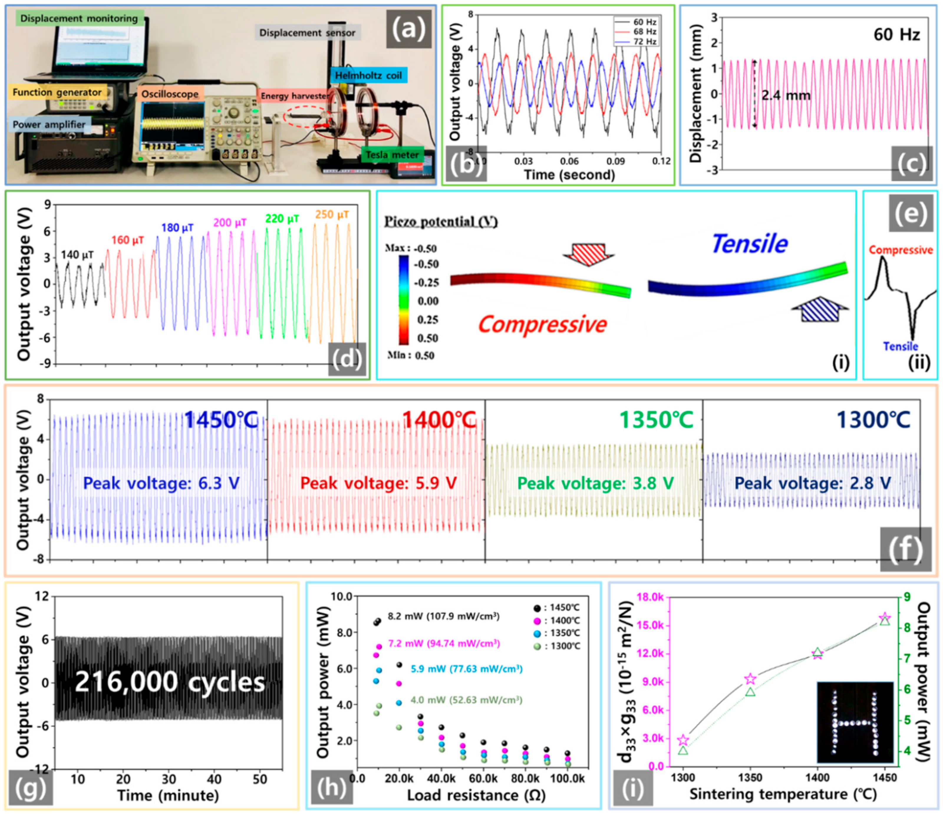
The experimental setup that was used to measure the output power and the displacement generated via piezoelectric energy harvesting driven by a Helmholtz coil is shown in Figure 3a. The LPEH has a tip magnet that indicates the energy harvester response of the designed cantilever structure. It has a permanent Nd magnet at its tip, which bends when an external magnetic AC field at 60 Hz is applied. The field is generated using the Helmholtz coils. Using a power amplifier and a function generator, the magnetic field of the Helmholtz coil was adjusted over the range of 140–250 μT and the magnetic field generated was measured using a tesla meter. In Figure 3b, these LPEHs were generated at various frequency conditions of the maximum power-generation characteristics of the BCTZC0.3 films at a sintering temperature of 1450 °C. To measure the resonance frequencies (Hz) of the fabricated LPEHs, we used Equation (2) with the following terms: E = Young’s modulus; L = beam length; I = moment of inertia; and m = tip mass. The physical properties of the LPEH (e.g., its length, mass, area, thickness, and Young’s modulus) determine its operational performance. The LPEH was designed to be tuned for a resonance frequency of 60 Hz. The calculated LPEH resonance frequency was about 60 Hz: E = 6.3 GPa, L = 9 × 10⁻² m, I = 1.1 × 10⁻¹⁰ m4, and m = 20 g.
The minimum output voltage (V) of the LPEH with the BCTZC0.3 film sintered at 1450 °C was 2.2 VOC at a frequency of 72 Hz, while the maximum output voltage was 6.3 V at a frequency of 60 Hz. The maximum displacement of the tip mass of the LPEH was found to be 2.4 cm at a frequency of 60 Hz. Figure 3d shows graphs of the LPEHs measured in terms of the electrical energy according to different magnetic fields (140–250 µT). The peak of the output voltage gradually improved as the magnetic field was increased to 250 µT. The maximum output voltage value was 6.3 VOC at a magnetic field of 250 µT. Figure 3e shows the results of simulations of the piezoelectric potential and voltage shapes during bending and unbending trials of the piezoelectric energy harvester, as determined using the ATILA software package. (Atila is a commercially available finite element analysis (FEA) software package developed specifically for the modeling and analysis of devices made of piezoelectric or magnetostrictive materials. The simulation study was conducted using ATILA (version 6.0.0.6) finite element analysis (FEA) software with a pre and post-GID (version 10.0.9) processor) [40,41]. A positive piezoelectric voltage is generated from compressive stress between the two electrodes when downward mechanical stress is applied. Otherwise, upward stress would lead to the generation of negative voltage from the tensile pressure. We can assume that the negative voltage and positive voltage outputs generated in the energy harvester are related to the direction in which the stress is applied. Figure 3f shows the open-circuit output voltage signals obtained from the LPEHs with the BCTZC0.3 films when plotted according to their sintering temperatures. The open-circuit output voltage also increases as the sintering temperature increases; the instantaneous maximum output voltage is 6.3 VOC at 1450 °C and the minimum output voltage is 2.65 VOC at 1300 °C. A mechanical durability experiment was performed to evaluate the practical applicability of the proposed LPEH. Figure 3g shows the results of output voltage measurements by the LPEH, demonstrating electromechanical stability for over 216,000 cycles for 60 min with bending displacement of 2 cm. As an indicated in Figure 3h, the instantaneous maximum output powers of the LPEHs with the BCTZC0.3 films sintered at various temperatures are dependent on the load resistance over the range of 100 Ω to 100 kΩ. To measure the output power (P), the peak value of the output voltage (V) applied to the load resistance (R) divided by this load resistance (R) is used in the following equation: P = V2/R. The output power (mW) increases steadily with an increase in the sintering temperature from 1300 to 1450 °C. The minimum output power of the LPEH with the BCTZC0.3 sintered at 1300 °C is 4.0 mW, while the maximum output power of the LPEH with the BCTZC0.3 sintered at 1450 °C is 8.2 mW. To measure the power density of each LPEH, the output power (P) and the volume (cm3) of the BCTZC0.3 film were used in the following equation: power density = P/volume. The minimum power density (mW/cm3) of the LPEH with the BCTZC0.3 film that was sintered at 1300 °C was 52.63 mW/cm3, while the maximum power density of the LPEH with the BCTZC0.3 that was sintered at 1450 °C was 107.9 mW/cm3. The energy-conversion constant values of the BCTZC0.3 samples with their sintering temperatures are closely related to the output power (mW) of the LPEH. Figure 3i presents graphs of the energy-conversion constants () and the output power (mW) levels of BCTZC0.3 films with respect to the sintering temperature. The inset shows the lighting of 30 white light-emitting diodes (LEDs). The graphs of the energy-conversion constant () and the output power (mW), show similar trends. For LPEHs using the BCTZC0.3 films, an increase in the energy-conversion constant () was found to factor into the improvement of the LPEH output power (mW). The LPEH with the BCTZC0.3 sintered at 1450 °C was selected for use as a power source in self-powering WSNs. These results clearly indicate that an energy harvester with a suitably high energy-conversion constant can convert energy in environments characterized by weak magnetic fields into a usable form of electrical energy. The output signals from the LPEH and other previously reported piezoelectric energy harvesters are indicated in Table 2.
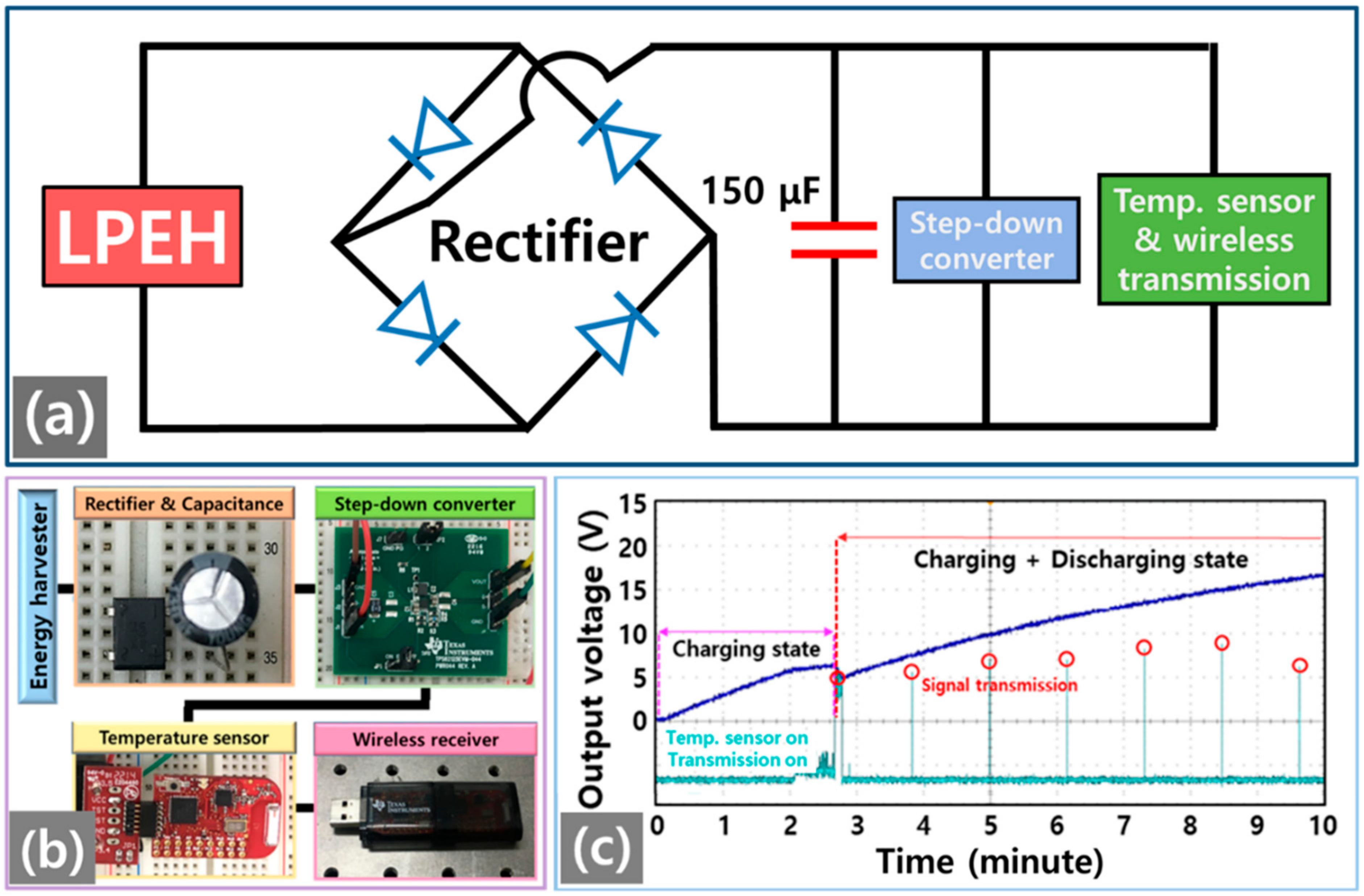
Figure 4a,b illustrates a promising application of the energy harvester, which is used to operate a WSN using the output voltage generated by the LPEH. The WSN system consists of a bridge rectifier, a capacitor, a step-down converter, a temperature sensor, 2.4 GHz wireless transmission, and a wireless receiver (with photographs of the WSN system components). The AC voltage generated by the LPEH was converted into DC voltage using the rectifier. To supply electric power stably, the capacitor was charged to supply the required power using DC voltage. Using the step-down converter, the supplied power is constantly reduced to enable the operation of both the temperature sensor and the wireless transmitter, and the data pertaining to the ambient temperature is transmitted to a computer. To verify the feasibility of the use of lead-free generators in practical applications, it was also necessary to evaluate the operation of the WSN system. Figure 4c presents the LPEH performance results after the successful charging of the capacitor (capacitance: 150 μF) up to 6.5 V over 2.8 min in a field of 250 μT. The energy generated by the harvester from the mechanical energy was used successfully to drive both a temperature sensor and a radio frequency transmitter using electricity that was first stored in a capacitor. The energy harvester generated the output voltage required to operate the WSN system in a magnetic field of 250 µT. The capacitor was charged to 6.5 V in 2.8 min and was then able to supply sufficient energy to drive the WSN system to measure the ambient temperature and transmit the measured data to a computer every 0.8 min. The LPEH device could also be used in bending and unbending applications with a magnetic field to operate the WSN system. The energy-harvesting system is capable of real-time sensing, based on transmissions to the WSN system, of the power generated from the AC magnetic field condition. This lead-free BCTZC0.3 with a high energy-conversion constant can transmit the temperature data wirelessly to a notebook computer. Self-powered WSN technologies combined with a real-time monitoring and management system require further investigation of lead-free piezoelectric energy device systems in advanced electronics.
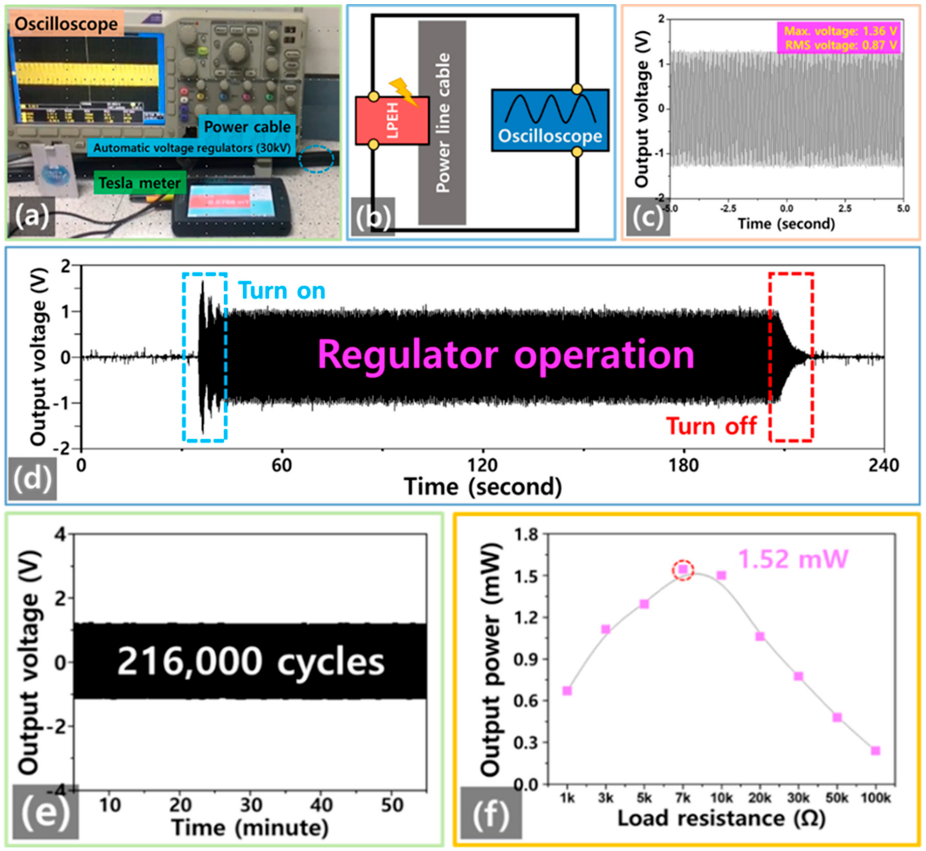
Figure 5a shows the experimental environment that was used to harvest electrical energy from the power-line cable of an automatic voltage regulator (30 kV). During operation of the automatic voltage regulator, we measured the LPEH’s electrical output performance. An energy-harvesting circuit diagram is presented in Figure 5b. For the automatic voltage regulator operation period, the output voltages were fixed at approximately 1.36 Vmax and 0.87 Vrms, shown in Figure 5c. Vertical displacement was generated by the LPEH at 60 Hz in a weak magnetic field of 78 μT. Total displacement of 0.8 mm was generated from the change in the magnetic force acting between the magnets of the LPEH. Figure 5d indicates that the LPEH generated an output voltage signal when the regulator was turned on and off. With regard to the regulator’s turn on step, the voltage signal was instantaneously increased to 1.8 V as overcurrent. When the regulator operated normally, the output voltage was generated constantly. When the regulator was turned off, the voltage signal level decreased abruptly. To demonstrate the durability of the proposed LPEH, the output performance was tested over a period of 216,000 cycles, with the results shown in Figure 5e. This verified that the magnetic-force-based power-generation mechanism of the LPEH offers high stability and an output voltage of approximately 1.32 V. This phenomenon can be attributed to confirmation of the development of the proposed BCTZC0.3-based LPEH as an energy source from weak magnetic fields. The output power from this lead-free piezoelectric energy harvester was 1.52 mW at load resistance of 7 kΩ in Figure 5f. These results fully demonstrate that the LPEH based on the BCTZC0.3 film could provide a reliable source of energy.
4. Conclusions
We developed a LPEH based on BCTZC0.3 with a high energy-conversion constant. With the lead-free BCTZC0.3 sintered at 1450 °C, we obtained both enhanced piezoelectric properties and improved energy-harvesting characteristics. The LPEH generated maximum output power that reached 8.2 mW. Moreover, an energy density of 107.9 mW/cm3 was achieved in a magnetic field of 250 µT, which was sufficient to drive 30 commercial LEDs. The BCTZC0.3-based LPEH demonstrated remarkable stability without performance degradation over 126,000 cycles. The module successfully overcame earlier restrictions on power generation when using a lead-free piezoelectric energy harvester, thus enabling its operation as a self-charging energy harvester in a WSN system. The LPEH supplied electrical energy (output power: 1.52 mW) constantly under a power-line cable with a weak 78 μT magnetic field. The proposed approach represents a significant advance in LPEHs based on BCTZC0.3 film research for self-powering sensors in magnetic fields that could be used in ubiquitous wireless communication systems and also demonstrates that the technology has great commercialization potential.
Supplementary Materials
The following are available online at https://www.mdpi.com/1996-1073/14/5/1346/s1, Figure S1: Rectifier of Self-powered wireless temperature monitoring system, Figure S2: Signal microcontroller of self-powered wireless temperature monitoring system, Figure S3: Surface FE-SEM images of the BCTZC0.3 ceramics sintered at different temperatures, Figure S4: Energy dispersive spectra (EDS) mapping analysis of the 1500 °C BCTZC0.3 composites, Figure S5: surface images of the BCTZC0.3 sample sintered at 1500 °C. Self-powered wireless temperature monitoring system and More material information can be found in the Supplementary Materials.
Author Contributions
Conceptualization, Q.W. and K.-B.K.; methodology, K.-B.K.; software, S.B.W.; validation, Q.W. and S.B.W.; formal analysis, Q.W. and K.-B.K.; investigation, Q.W. and K.-B.K.; resources, Q.W.; data curation, S.B.W.; writing—original draft preparation, Q.W.; writing—review and editing, Q.W. and T.H.S.; visualization, S.B.W.; supervision, K.-B.K. and T.H.S.; project administration, K.-B.K.; funding acquisition, K.-B.K. All authors have read and agreed to the published version of the manuscript discussions.
Funding
This work was funded by the Korea Institute of Energy Technology Evaluation and Planning (KETEP) and by the Ministry of Trade, Industry, and Energy (MOTIE) of the Republic of Korea (No. 2018201010636A). This research was supported by the Basic Science Research Program through the National Research Foundation of Korea(NRF) funded by the Ministry of Education (2019R1I1A1A01046810).
Institutional Review Board Statement
Not applicable.
Informed Consent Statement
Informed consent was obtained from all subjects involved in the study.
Data Availability Statement
Data is contained within the article or Supplementary Materials. The data presented in this study are available in the article or Supplementary Materials.
Acknowledgments
This work was supported by the Korea Institute of Energy Technology Evaluation and Planning (KETEP) and by the Ministry of Trade, Industry, and Energy (MOTIE) of the Republic of Korea (No. 2018201010636A). Sample images were analyzed on the FEI Scios device installed at the Hanyang LINC+ 334 Analytical Equipment Center in Seoul. This research was supported by the Basic Science Research Program through the National Research Foundation of Korea (NRF) funded by the Ministry of Education (2019R1I1A1A01046810).
Conflicts of Interest
The authors declare that they have no known competing financial interests or personal relationships that could have appeared to influence the work reported in this paper.
References
- Siddique, A.R.M.; Mahmud, S.; Van Heyst, B. A comprehensive review on vibration based micro power generators using electromagnetic and piezoelectric transducer mechanisms. Energy Convers. Manag. 2015, 106, 728–747. [Google Scholar] [CrossRef]
- Yildirim, T.; Ghayesh, M.H.; Li, W.; Alici, G. Design and development of a parametrically excited nonlinear energy harvester. Energy Convers. Manag. 2016, 126, 247–255. [Google Scholar] [CrossRef] [Green Version]
- Lee, T.G.; Lee, H.J.; Kim, D.H.; Xu, H.; Park, S.; Park, J.S. Relation between structure and piezoelectric properties of (1-xy)PbZrO3-xPbTiO3-yPb(Ni1/3Nb2/3)O3 ceramics near triple point composition. J. Eur. Ceram. Soc. 2016, 36, 4049–4057. [Google Scholar] [CrossRef]
- Ryu, J.; Kang, J.-E.; Zhou, Y.; Choi, S.-Y.; Yoon, W.-H.; Park, D.-S.; Choi, J.-J.; Hahn, B.-D.; Ahn, C.-W.; Kim, J.-W.; et al. Ubiquitous magneto-mechano-electric generator. Energy Environ. Sci. 2015, 8, 2402–2408. [Google Scholar] [CrossRef]
- Uzun, Y.; Kurt, E. Performance exploration of an energy harvester near the varying magnetic field of an operating induction motor. Energy Convers. Manag. 2013, 72, 156–162. [Google Scholar] [CrossRef]
- Ryu, J.; Carazo, A.V.; Uchino, K.; Kim, H.-E. Magnetoelectric Properties in Piezoelectric and Magnetostrictive Laminate Composites. Jpn. J. Appl. Phys. 2001, 40, 4948–4951. [Google Scholar] [CrossRef]
- Zhang, J.; Wang, C.; Bowen, C. Piezoelectric effects and electromechanical theories at the nanoscale. Nanoscale 2014, 6, 13314–13327. [Google Scholar] [CrossRef]
- Tadesse, Y.; Zhang, S.; Priya, S. Multimodal Energy Harvesting System: Piezoelectric and Electromagnetic. J. Intell. Mater. Syst. Struct. 2008, 20, 625–632. [Google Scholar] [CrossRef]
- Saadon, S.; Sidek, O. A review of vibration-based MEMS piezoelectric energy harvesters. Energy Convers. Manag. 2011, 52, 500–504. [Google Scholar] [CrossRef]
- Howells, C.A. Piezoelectric energy harvesting. Energy Convers. Manag. 2009, 50, 1847–1850. [Google Scholar] [CrossRef]
- Zhang, X.; Zhang, Z.; Pan, H.; Salman, W.; Yuan, Y.; Liu, Y. A portable high-efficiency electromagnetic energy harvesting system using supercapacitors for renewable energy applications in railroads. Energy Convers. Manag. 2016, 118, 287–294. [Google Scholar] [CrossRef]
- Shi, Y.; Yao, H.; Gao, Y. A functionally graded composite cantilever to harvest energy from magnetic field. J. Alloys Compd. 2017, 693, 989–999. [Google Scholar] [CrossRef]
- He, W.; Li, P.; Wen, Y.; Zhang, J.; Yang, A.; Lu, C.; Yang, J.; Wen, J.; Qiu, J.; Zhu, Y.; et al. Piezoelectric energy harvester scavenging AC magnetic field energy from electric power lines. Sens. Actuators A 2013, 193, 59–68. [Google Scholar] [CrossRef]
- Annapureddy, V.; Palneedi, H.; Hwang, G.T.; Peddigari, M.; Jeong, D.Y.; Yoon, W.H.; Kim, K.H.; Ryu, J. Magnetic energy harvesting with magnetoelectrics: An emerging technology for self-powered autonomous systems. Sustain. Energy Fuels 2017, 1, 2039–2052. [Google Scholar] [CrossRef]
- Fan, K.; Chang, J.; Chao, F.; Pedrycz, W. Design and development of a multipurpose piezoelectric energy harvester. Energy Convers. Manag. 2015, 96, 430–439. [Google Scholar] [CrossRef]
- Islam, R.A.; Priya, S. Realization of high-energy density polycrystalline piezoelectric ceramics. Appl. Phys. Lett. 2006, 88, 032903. [Google Scholar] [CrossRef]
- Priya, S.; Uchino, K.; Ryu, J.; Ahn, C.-W.; Nahm, S. Induction of combinatory characteristics by relaxor modification of Pb(Zr0.5Ti0.5)O3. Appl. Phys. Lett. 2003, 83, 5020–5022. [Google Scholar] [CrossRef]
- APC. Piezoelectric Ceramics: Principles and Applications; APC: Paris, France, 2002. [Google Scholar]
- Seo, I.-T.; Cha, Y.-J.; Kang, I.-Y.; Choi, J.-H.; Nahm, S.; Seung, T.-H.; Paik, J.-H. High Energy Density Piezoelectric Ceramics for Energy Harvesting Devices. J. Am. Ceram. Soc. 2011, 94, 3629–3631. [Google Scholar] [CrossRef]
- Kim, H.; Priya, S.; Stephanou, H.; Uchino, K. Consideration of Impedance Matching Techniques for Efficient Piezoelectric Energy Harvesting. IEEE Trans. Ultrason. Ferroelectr. Freq. Control. 2007, 54, 1851–1859. [Google Scholar] [CrossRef]
- Ajitsaria, J.; Choe, S.Y.; Shen, D.; Kim, D.J. Modeling and analysis of a bimorph piezoelectric cantilever beam for voltage generation. Smart Mater. Struct. 2007, 16, 447–454. [Google Scholar] [CrossRef]
- Lee, H.; Jang, H.; Park, J.; Jeong, S.; Park, T.; Choi, S. Design of a Piezoelectric Energy-Harvesting Shock Absorber System for a Vehicle. Integr. Ferroelectr. 2013, 141, 32–44. [Google Scholar] [CrossRef]
- Kong, N.; Ha, D.S.; Erturk, A.; Inman, D.J. Resistive Impedance Matching Circuit for Piezoelectric Energy Harvesting. J. Intell. Mater. Syst. Struct. 2010, 21, 1293–1302. [Google Scholar] [CrossRef]
- Brufau-Penella, J.; Puig-Vidal, M. Piezoelectric Energy Harvesting Improvement with Complex Conjugate Impedance Matching. J. Intell. Mater. Syst. Struct. 2008, 20, 597–608. [Google Scholar] [CrossRef]
- Jaffé, B.; Roth, R.; Marzullo, S. Properties of piezoelectric ceramics in the solid-solution series lead titanate-lead zirconate-lead oxide: Tin oxide and lead titanate-lead hafnate. J. Res. Natl. Inst. Stand. Technol. 1955, 55, 239. [Google Scholar] [CrossRef]
- Chen, H.D.; Udayakumar, K.R.; Gaskey, C.J. Electrical properties’ maxima in thin films of the lead zirconate–lead titanate solid solution system. App. Phys. Lett. 1995, 67, 3411–3413. [Google Scholar] [CrossRef]
- Liu, W.L.; Ren, X. Correlation of grain size, phase transition and piezoelectric properties in Ba0.85Ca0.15Ti0.90Zr0.10O3 ceramics. Phys. Rev. Lett. 2009, 103, 257602. [Google Scholar] [CrossRef] [PubMed] [Green Version]
- Wang, P.; Li, Y.; Lu, Y. Enhanced piezoelectric properties of (Ba0.85Ca0.15)(Ti0.9Zr0.1)O3 lead-free ceramics by optimizing calcination and sintering temperature. J. Eur. Ceram. Soc. 2011, 31, 2005–2012. [Google Scholar] [CrossRef]
- Yao, Y.; Mak, C.L. Effects of Ca-dopant on the pyroelectric, piezoelectric and dielectric properties of (Sr0.6Ba0.4)4Na2Nb10O30 ceramics. J. Alloys Compd. 2012, 544, 87–93. [Google Scholar] [CrossRef]
- Marcos, F.R.; Reinosa, J.J.; Vendrell, X.; Romero, J.; Mestres, L.; Leret, P.; Fernández, J.; Marchet, P. Structure, microstructure and electrical properties of Cu2+ doped (K,Na,Li)(Nb,Ta,Sb)O3 piezoelectric ceramics. Ceram. Int. 2013, 39, 4139–4149. [Google Scholar] [CrossRef]
- Hagh, N.M.; Kerman, K.; Jadidian, B.; Safari, A. Dielectric and piezoelectric properties of Cu2+-doped alkali Niobates. J. Eur. Ceram. Soc. 2009, 29, 2325–2332. [Google Scholar] [CrossRef]
- Dhakar, L.; Liu, H.; Tay, F.E.H.; Lee, C. A new energy harvester design for high power output at low frequencies. Sens. Actuators A Phys. 2013, 199, 344–352. [Google Scholar] [CrossRef]
- Yue, Y.; Hou, Y.; Zheng, M.; Yan, X.; Fu, J.; Zhu, M. High power density in a piezoelectric energy harvesting ceramic by optimizing the sintering temperature of nanocrystalline powders. J. Eur. Ceram. Soc. 2017, 37, 4625–4630. [Google Scholar] [CrossRef]
- Liu, Y.; Chang, Y.; Sun, E.; Li, F.; Zhang, S.; Yang, B.; Sun, Y.; Wu, J.; Cao, W. Significantly Enhanced Energy-Harvesting Performance and Superior Fatigue-Resistant Behavior in [001]c-Textured BaTiO3-Based Lead-Free Piezoceramics. ACS Appl. Mater. Interfaces 2018, 10, 31488–31497. [Google Scholar] [CrossRef] [PubMed]
- Kim, K.-B.; Kim, C.-I.; Jeong, Y.H.; Lee, Y.-J.; Cho, J.-H.; Paik, J.-H.; Nahm, S. Performance of unimorph cantilever generator using Cr/Nb doped Pb(Zr0.54Ti0.46)O3 thick film for energy harvesting device applications. J. Eur. Ceram. Soc. 2013, 33, 305–311. [Google Scholar] [CrossRef]
- Oh, Y.; Noh, J.; Yoo, J.; Kang, J.; Hwang, L.; Hong, J. Dielectric and piezoelectric properties of CeO2-added nonstoichiometric (Na0.5K0.5)0.97(Nb0.96Sb0.04)O3 ceramics for piezoelectric energy harvesting device applications. IEEE Trans. Ultrason. Ferroelectr. Freq. Control. 2011, 58, 1860–1866. [Google Scholar] [CrossRef]
- Wu, J.; Shi, H.; Zhao, T.; Yu, Y.; Dong, S. High-Temperature BiScO3-PbTiO3Piezoelectric Vibration Energy Harvester. Adv. Funct. Mater. 2016, 26, 7186–7194. [Google Scholar] [CrossRef]
- Seo, I.-T.; Choi, C.-H.; Song, D.; Jang, M.-S.; Kim, B.-Y.; Nahm, S.; Kim, Y.-S.; Sung, T.-H.; Song, H.-C. Piezoelectric Properties of Lead-free Piezoelectric Ceramics and Their Energy Harvester Characteristics. J. Am. Ceram. Soc. 2013, 96, 1024–1028. [Google Scholar] [CrossRef]
- Yan, X.; Zheng, M.; Hou, Y.; Zhu, M. Composition-driven phase boundary and its energy harvesting performance of BCZT lead–free piezoelectric ceramic. J. Eur. Ceram. Soc. 2017, 37, 2583–2589. [Google Scholar] [CrossRef]
- Uchino, K.; Debus, J.C. Applications of ATILA FEM Software to Smart Materials: Case Studies in Designing Devices; Woodhead Publishing Limited: Cambridge, UK, 2012. [Google Scholar]
- Uchino, K. FEM and Micromechatronics with ATILA Software; CRC Press: Boca Raton, FL, USA, 2008. [Google Scholar]
Figure 1.
(a) Schematic of magnetic field energy harvesting using a lead-free piezoelectric device for a wireless sensor network. (b) Photograph of the lead-free piezoelectric energy harvester (LPEH) device, with the inset showing the piezoelectric film of BCTZC0.3 sintered at 1450 °C. (c) XRD graphs of BCTZC0.3 ceramics sintered at various temperatures. (d) Surface field emission-scanning electron microscope (FE-SEM) images of the BCTZC0.3 ceramics sintered at different temperatures. (e) X-ray photoelectron spectroscopy (XPS) component analysis graphs of the BCTZC0.3 ceramic sintered at 1450 °C. (f) Energy dispersive spectra (EDS) mapping analysis of the BCTZC0.3 composites.

Figure 2.
Piezoelectric and dielectric properties of the BCTZC0.3 ceramics sintered at various temperatures.
Figure 2.
Piezoelectric and dielectric properties of the BCTZC0.3 ceramics sintered at various temperatures.

Figure 3.
(a) Photograph of the experimental environment used to observe the power-generation characteristics of the LPEH in various magnetic fields (μT). (b) Open-circuit output voltage (V) of the LPEH at various frequencies. (c) Displacement of the LPEH at a resonance frequency of 60 Hz. (d) Open-circuit output voltage (V) of the LPEH in differential magnetic fields (μT). (e) Simulated data of the piezoelectric potential (V) when stress is applied. (f) Open-circuit output voltage (V) characteristics of LPEHs composed of BCTZC0.3 films processed at various sintering temperatures (°C). (g) Open-circuit output voltage of the LPEH for a durability test of over 216,000 cycles performed in a magnetic field of 250 μT. (h) Instantaneous maximum output power (mW) values of LPEHs with BCTZC0.3 films sintered at various temperatures (°C) under specific load resistances (Ω) for impedance matching. (i) Power conversion constant and instantaneous maximum output power (mW) values of LPEHs with BCTZC0.3 films, depending on their sintering temperatures (°C). The inset shows lighting when using 30 white light-emitting diodes.

Figure 4.
(a) Circuit diagram of self-powered wireless temperature monitoring system powered with the LPEH in a magnetic field of 250 µT. (b) Photograph images of the self-powered wireless temperature monitoring system (see Supporting Information Figures S1 and S2). (c) Characteristics of the self-charging voltage that drives the temperature sensor and radio-frequency (RF) transmission using a capacitor of 150 μF with the LPEH in a magnetic field of 250 µT.

Figure 5.
(a) Experimental setup to test the energy-harvesting performance from the power-line cable of an automatic voltage regulator (30 kV). (b) Diagram of the energy-harvesting circuit with the LPEH. (c) Open-circuit voltage of the LPEH from the magnetic field of a power-line cable. (d) Open-circuit voltage of the LPEH under a regulated turn-on and -off condition. (e) Open-circuit voltage of the LPEH for a durability test over 216,000 cycles performed in a weak magnetic field of 78 µT. (f) Output power of the LPEH in the magnetic field of a power-line cable as a function of the load resistance (range of 1 kΩ to 100 kΩ).


Table 1.
Piezoelectric and dielectric properties of BCTZC0.3 samples according to their sintering temperatures.
Table 1.
Piezoelectric and dielectric properties of BCTZC0.3 samples according to their sintering temperatures.
| Sintering Temperature (°C) | Dielectric Constant | Density (g/cm3) | d33 (pC/N) | g33 (10−3 Vm/N) | kp (%) | d33 × g33 (10−15 m2/N) | Efficiency (η) |
|---|---|---|---|---|---|---|---|
| 1300 | 2500.4 | 1.37 | 265 | 10.6 | 46.8 | 2809 | 0.88 |
| 1350 | 3016.6 | 1.40 | 530 | 17.6 | 41.6 | 9322 | 0.89 |
| 1400 | 1734.3 | 1.54 | 456 | 26.3 | 44.6 | 11,990 | 0.85 |
| 1450 | 1976.2 | 1.48 | 526 | 30.0 | 49.3 | 15,780 | 0.84 |
Table 2.
The output signals from the LPEH and other previously reported piezoelectric energy harvesters.
Table 2.
The output signals from the LPEH and other previously reported piezoelectric energy harvesters.
| Material | d33 × g33 (10−15 m2/N) | Frequency (Hz) | Acceleration (m/s2) | Power (mW) | Power Density (mW/cm3) | Ref. |
|---|---|---|---|---|---|---|
| PZT-5A bullk | 9.3 k | 36 | 2 | 0.040 | 0.38 | [30] |
| PZN-PZT + MnO2 | - | 90 | 10 | 0.098 | 1.5 | [31] |
| PZT-5H bulk | 11.7 k | 40 | - | 0.11 | 3.82 | [32] |
| PZT-CN | 14 k | 20 | - | 0.11 | 3.82 | [32] |
| This work (BCTZ0.3C) | 15.8 k | 60 | - | 82 | 107.9 | - |
| KNNS bulk | - | 70 | 7 | 0.008 | 0.01 | [34] |
| BS-PT bulk | - | 41 | 10 | 0.013 | 0.08 | [35] |
| CNKN bulk | 4.9 k | 93 | - | - | 12 | [36] |
| BCTZ bulk | - | 90 | 10 | 0.07 | 1.4 | [37] |
Publisher’s Note: MDPI stays neutral with regard to jurisdictional claims in published maps and institutional affiliations. |
© 2021 by the authors. Licensee MDPI, Basel, Switzerland. This article is an open access article distributed under the terms and conditions of the Creative Commons Attribution (CC BY) license (http://creativecommons.org/licenses/by/4.0/).
Share and Cite
MDPI and ACS Style
Wang, Q.; Kim, K.-B.; Woo, S.B.; Sung, T.H. Magnetic Field Energy Harvesting with a Lead-Free Piezoelectric High Energy Conversion Material. Energies 2021, 14, 1346. https://doi.org/10.3390/en14051346
AMA Style
Wang Q, Kim K-B, Woo SB, Sung TH. Magnetic Field Energy Harvesting with a Lead-Free Piezoelectric High Energy Conversion Material. Energies. 2021; 14(5):1346. https://doi.org/10.3390/en14051346
Chicago/Turabian StyleWang, Quan, Kyung-Bum Kim, Sang Bum Woo, and Tae Hyun Sung. 2021. "Magnetic Field Energy Harvesting with a Lead-Free Piezoelectric High Energy Conversion Material" Energies 14, no. 5: 1346. https://doi.org/10.3390/en14051346
Note that from the first issue of 2016, this journal uses article numbers instead of page numbers. See further details here.