Fire Behavior of Electrical Installations in Buildings


Instytut Techniki Budowlanej, Filtrowa 1, 00-611 Warszawa, Poland
*
Author to whom correspondence should be addressed.
Energies 2020, 13(23), 6433; https://doi.org/10.3390/en13236433
Submission received: 1 October 2020
/
Revised: 27 November 2020
/
Accepted: 1 December 2020
/
Published: 4 December 2020
(This article belongs to the Special Issue DC and AC Insulated Power Cables and Hybrid Transmission Lines: Insights, Operating Experiences and New Challenges)
Abstract
:Electrical installations are a significant component of fire load inside a building, although they are often neglected in the overall fire safety analysis and are not subjected to any kind of fire safety evaluation of a building. A typical electrical installation unconnected to the mains was experimentally studied using a single burning item (SBI) test apparatus, fixed to two types of popular non-combustible or combustible (wooden-based) backgrounds simulating a typical building internal wall or ceiling. The semi-real scale test showed that poly(vinyl chloride) (PVC) cable, commonly used in installations in buildings in Europe and used in SBI tests, showed high fire properties related to heat release, smoke production and flame spread to other interior elements. The results of the electrical circuit connected to the main measurements carried out showed a significant impact of the heating effect towards the uncovered surface socket, causing the possibility of easy ignition inside the installation. In conclusion, it was found that even a relatively simple and short section of electrical installation resulted in a significant increase in the heat release rate and smoke generation parameters, obtained during the SBI tests, and as a consequence a reduction of one or two reaction to fire euroclasses of construction materials for internal walls.
1. Introduction
The first attempt at regulating the use of electrical installations dates to 1907 [1], while more recent exemplary contributions on this subject are the works of [2,3,4,5]. McClung and Hill [3] pointed out “a need to capture in one location the wealth of electrical system design techniques that have been published in recent IEEE papers and other industry sources”. One of the newest national standards in this field is the British BS 7671 [6] published in 2008. In 2011, electric cables were added to the list of construction products in Europe [7]. Such building products like electrical cables and their installation ducts may cover an unexpectedly large surface inside buildings, often up to several hundred meters in one room or thousands of meters in one residential building, substantially increasing its overall fire load.
There are different types of electrical installations inside the building, which can be divided by their application as follows:
- -
- Power supply installations
- -
- Telecommunication and information network
- -
- Intercom, antenna and alarm systems
- -
- Lightning protection systems
A highly valuable and complete critical review of research on one of the most important types of structure fires—when the flow of electric current or static electricity causes fire on electrical appliances—was published by Babrauskas [8], who summarized as follows: “Despite the importance of electrical fires, there has not been any institution in the English-speaking world with a long-term commitment to research in this area. Worldwide, the situation has been much better, due to extensive research in Japan. But most of this body of work was only published in the Japanese language and, consequently, had been unavailable to most scientists and engineers in English-language countries”. Later, Barros and Diego [9] presented an extensive critical literature review of considerations on the safe use of electric installations in ships. They discussed voltage and frequency fluctuations, transient and voltage notching, voltage dips and surges, fault detection and its classification, harmonic distortion and voltage imbalance. Moreover, power quality instrumentation and electrical installation safety rules in ships were also considered. Some of these findings are certainly applicable to buildings as well. The new fire research area has grown as a result of an increasing number of roof fires caused by photovoltaic installations, among others, Backstrom and Dini [10], Falvo and Capparella [11] and Manzini et al. [12]. Internal fires and their impact on residential electrical installations were studied, for example by Plumecocq et al. [13], Huang et al. [14] and Novak et al. [15]. Very few examples of modelling of electrical installations are works done for instance by Van Hees et al. [16], Janssens et al. [17] and Matsuda [18]. The last two contributions focused on risk analyses for the purpose of the safety of nuclear plants. An increasing number of works have been published on the fire properties and fire behavior of single electric cable or bunched cables, among others, the recent authors’ works [19,20]. An earlier single burning item (SBI) test of cables was performed by Breulet and Steenhuizen [21]. They investigated twin bundles of electric cables mounted on a substrate in the SBI test and compared it to EN 50266-2-4 large-scale vertical cable test results of flame spread, heat release and ability for ranking of various cables for the purpose of their evaluation and fire classification as building products. It was found that flame spread results would not be compared, while heat and smoke release parameters (total heat release (THR600s), heat release rate (peakHRR), fire grown rate (FIGRA), total smoke rate (TSR)) for both methods could be adequate. Hirschler [22] examined electric cables of the same construction but having various chemical composition of their sheath and insulation in a large scale cable tray test (ASTM D 9.21) modified to measure total heat release (THR), heat release rate (HRR) and total smoke release (TSR), as well as a small scale cone calorimeter test (ASTM E 1354). Grayson et al. [23] presented studies for the group of 10 various cables in trays (for cables of diameter > 5 mm) or bundles (cables of diameter < 5 mm) not connected to the mains tested in 9 horizontal (H) or vertical (V) configurations in open, semi-open or closed spaces by means of several fire scenarios in order to develop a fire test method for cables designed for different applications (buildings, power plants, tunnels, vehicles or aircrafts). Moreover, the cone calorimeter test and model calculations were performed. Finally, the behavior of building products in the general context of fire safety was discussed by Fangrat in [24].
Due to aesthetic reasons, these multiplied electric cables connected to devices of various types and purposes are hidden in buildings, for instance, either below the raised floors or over the suspended ceilings, or at least inside PVC cable channels and on cable trays. Therefore, circuit electrical installations should be evaluated in terms of fire safety like any other construction product, which is in line with the earlier above-mentioned findings of other researchers.
For the purposes of this article, the fire properties of electrical installations newly built from new materials and not subjected to aging processes were analyzed.
2. Evaluation of Electrical Installation under Fire Conditions
A risk of fire has to be taken into account for each electrical installation when designing the component circuit and device, when selecting the material in order to reducing the likelihood of a fire and also in cases of their unpredictable and abnormal use and faulty operation or damage. The main goal is to prevent an ignition caused by the part supplied by electric power, and when the ignition and fire occurs, restricting the fire within the limits of the electrical equipment. In a case when the surfaces of electrical products are exposed to an external fire, it is necessary to ensure that they do not contribute to a further spread of the fire to the construction materials and structures in their vicinity.
Some electrical products, such as insulated cables and installation pipes, may in practice occupy large areas of a building’s structure and their finishing materials or may pass through firewalls. In such cases, electrical products exposed to an external fire should be assessed from the point of view of their contribution to the fire hazard, compared to the contribution of construction materials or a structure without the electrical installation.
The fire hazard presented by electric equipment depends on its properties, operational conditions and the properties of the environment. That is why a fire hazard assessment procedure should specify the description of the product, the conditions of its operation and the environment. These are elements in the process of evaluation for construction products in terms of fire safety according to European Committee for Standardization (CEN) procedures based on [25,26].
The first stage—fire scenario—is the most important one, because it answers the question, “What kind of fire will be considered?” The answer allows for the design of a new method or the choice to maintain the existing experimental method to test the product or element.
The second stage—criteria—defines the evaluation criteria (limits) aiming for the settlement of fire safety measures in order to compare the behavior of different products under the defined conditions of a chosen fire scenario at stage (1). Then, the evaluation limits can be established in terms of (i) health and life safety and (ii) loss of property. Indirect methods are also very useful at this stage.
The third stage is the interpretation of test results obtained during experimental and indirect methods of analysis performed in stage (2), leading to the fourth stage (4), which is an evaluation of the assignment of a class (e.g., euroclass).
3. Research Problem
The main goal of a fire hazard analysis in a building is to reduce the risk of fires initiated by electrical phenomena inside electrical products and, if such fire occurs, to restrict the spread of fire. External exposures should also be taken into account, such as the occurrence of a fire in its environment, but they are often neglected because they are treated as secondary, less important phenomena.
This study aimed to examine the behavior of an electrical circuit installation unconnected to the mains under internal wall fire conditions in a corner configuration utilizing the single burning item (SBI) scenario approach.
The chosen experimental method was the standard CEN test [27] applied for an evaluation of construction products in Europe (classes A2, B, C, D). To the authors’ best knowledge, the circuit electrical installation had not yet been tested by means of the SBI test method. Moreover, the power cable was examined by means of the semi-real scale standard CEN test EN 50,399 [28] Additionally, in order to evaluate the influence of an electrical current overload, the experiments of the electrical installations connected to the mains and fixed on both combustible or non-combustible substrates were performed.
4. Experiments
In order to investigate the interaction between the specimen section of a typical electrical installation fixed to combustible or non-combustible substrates (simulating building walls) and to determine the fire properties of such electrical installations, the semi-real laboratory scale tests known as the single burning item (SBI) tests were performed according to EN 13,823 [27] (Series A, Section 4.1). Moreover, the power cable was examined by means of the semi-real scale standard CEN test EN 50,399 [28] (Series B, Section 4.2). Additionally, the experiments of the electrical installations connected to the mains and fixed to both combustible or non-combustible substrates were performed (Series C, Section 4.3).
4.1. Series A—Main Experiments of Electrical Installations by Means of SBI Apparatus
4.1.1. Single Burning Item (SBI) Experimental Apparatus
The SBI test facility consisted of the following main parts:
- -
- Test room with the inner dimensions 2.4 m (height) and 3 m × 3 m floor area. The walls were made of calcium silicate, non-combustible material of class A1 according to EN 13,501-1 [26],
- -
- the test apparatus (trolley, frame, burners, hood, collector and ducting),
- -
- the smoke exhaust system,
- -
- general measuring equipment [27].
The front wall of the test room had an opening (1.38 m (width) × 2.13 m (height)) to insert the trolley into the test room. Windows were placed in the two walls facing the front side of the two perpendicular specimen planes. With the trolley in place in the test room, the distance between the long wing specimen surface touching the U-profile and the wall of the test room was equal to 2.10 m [27].
Additional parts of the experimental setup were as follows:
- -
- A trolley, on which two perpendicular specimen parts were placed, with a sandbox burner at the bottom of the vertical corner,
- -
- a large wing (1.00 m × 1.50 m) and a small wing (0.49 m × 1.50 m), which were mounted in a left angle and create a corner (Figure 1),
- -
- a gas burner (Figure 1) with a heat release rate of 30 kW located in the corner during the testing (dimensions of 249 × 249 mm),
- -
- a hood, on top of the frame, which collected the combustion gases through a collector located on top of the hood with baffles and a horizontal outlet for the exhaust duct, which were (J-shaped), a circular tube with an inner diameter of 315 mm and insulated with 50 mm high-temperature resistant mineral wool [27].
In the course of the experiments, the parameters such as fire grow rate index (FIGRA0.2MJ, FIGRA0.4MJ, W/s), heat release rate (HRR, kW), total heat release (THR, MJ), smoke production rate (SMOGRA, cm2/s) and total smoke production (TSP, m2) were measured. Burning droplets/particles and lateral flame spread (LFS, m) were observed visually. The apparatus was calibrated before the tests.
4.1.2. Specimens
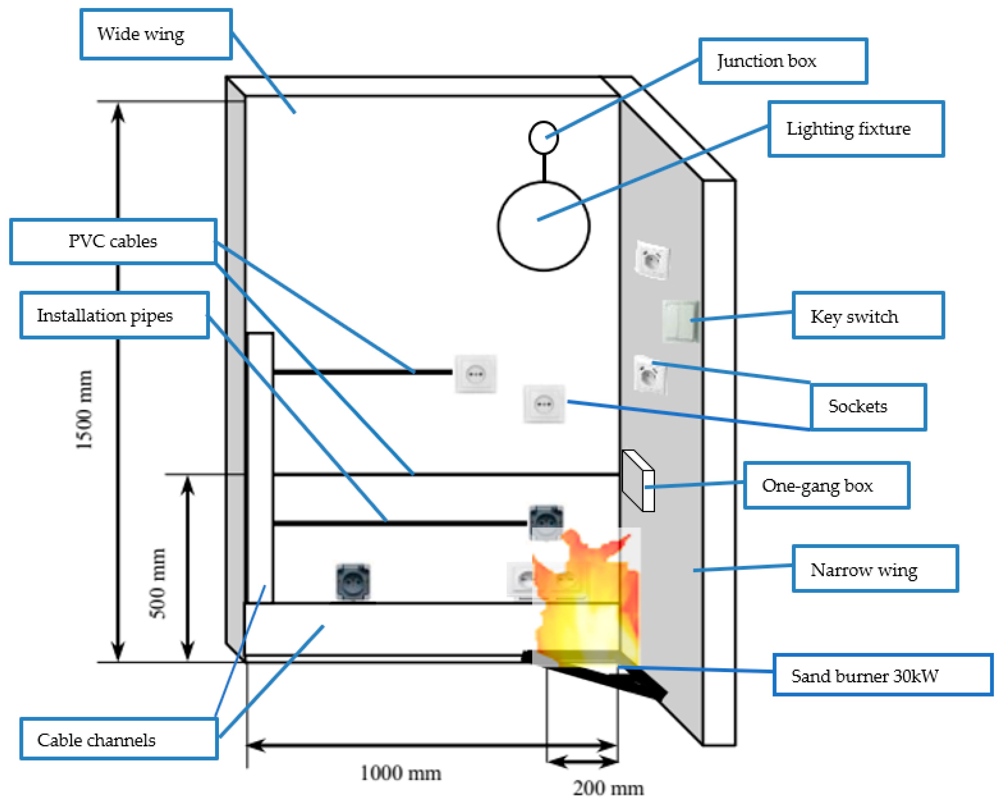
An electrical installation typical for a residential building unconnected to the mains was experimentally studied on two types of background (substrates) of different combustible properties. It was permanently fixed to the background (Figure 2) as a component of specimen 1 (on a combustible substrate) and specimen 2 (on a non-combustible substrate). All elements of electrical installations were brand new, available on the market. The electrical installation is described in further detail in Section 4.3.
Additionally, both substrates were studied separately without any electrical installation as reference specimens (number 3 and 4) by means of the SBI method in order to compare the outputs and to investigate their own fire behavior. Each of the tested specimens was previously conditioned in the conditioning chamber in the laboratory, according to the EN 13,238 standard requirements, at a constant temperature of 23 ± 2 °C and relative humidity of 50 ± 5%. The details of all wall specimens examined at SBI apparatus were as follows:
- -
- -
- -
- Specimen 3—wall made of combustible material (wood particleboard (oriented strand board, OSB) 15 mm in thickness) without mounted circuit electrical installation.
- -
- Specimen 4—wall made of non-combustible material (calcium-silicate board) without mounted circuit electrical installation.
4.1.3. Experimental Measurements and Visual Observations
The following parameters and observations were registered during each SBI experiment:
- -
- heat generation: FIGRA0.2MJ, FIGRA0.4MJ, THR600s
- -
- smoke emission: SMOGRA, TSP600s
- -
- presence of burning droplets and particles
- -
- lateral flame spread (LFS)
FIGRA0.2MJ and FIGRA0.4MJ (W/s) are maxima of the quotients of heat release rate from the specimen and the time of its occurrence using THR-thresholds of MJ relatively, where THR600s (MJ) is total heat release from the specimen in the first 600 s of exposure to the main (primary) burner flames, TSP600s (m2) is total smoke production from the specimen in the first 600 s of exposure to the main (primary) burner flames and LFS (m) is lateral flame spread (maximum range) on a wider specimen wing [27].
In the course of the SBI experiments, test specimens were exposed to the flames from a burner placed at the bottom side in the specimen corner (the “main (primary) burner”). The test duration was 25 min. The specimen properties measured in the course of the experiment were based on heat (HRR) and smoke (SPR) generation (conducted automatically), the range of flame spread in horizontal direction (FS) as well as presence of flaming droplets and particles (visual observation). The secondary burner of the same construction as the main primary burner was used for calibration of set-up just before ignition of the primary burner. The measuring section with the equipment for measuring the temperature, light attenuation, O2 and CO2 concentrations and pressure change was installed in the exhaust duct. [26].
During the thermal decomposition of the non-metallic elements of electrical installations, fire effluents were produced and transferred through the hood into the ventilation duct, where the measurements were performed by means of gas analysis and oxygen depletion.
The maximum value of the FIGRA parameter (equal to 1060 W/s) was obtained in 516 s of test duration for the electrical installation mounted on the combustible substrate (specimen 1 in Figure 3), while for the substrate itself a three times lower value was obtained (specimen 2 in Figure 3). It clearly shows the significant role of the electrical installation in the development of fire on the combustible wall (e.g., wood-based material). Such behavior was not observed in the case of specimen 2 (non-combustible substrate). Due to a lack of fire spread over the surface of the non-combustible substrate, the electrical installation was not involved in the combustion process; therefore, a very limited heat release similar to the substrate itself was measured (specimen 2 and 4 in Figure 3).
Specimen 1
The combustible specimen was examined at an initial ambient temperature of 23.0 °C and humidity of 58%. Visual observations were as follows:
- -
- 120 s—the ignition of the main burner electrical circuit, which was surface-mounted in a polypropylene fluted pipe, began to burn, spreading the flame. Burning drops of polypropylene fell on the perimeter located below, made in a PVC pipe, igniting along its entire length. However, the fire spread progressed slowly along the PVC installation. Ignition points were topical, but smoke was visible.
- -
- 460 s—the lampshade of the lighting fixture cracked, which was located above the source of the fire.
- -
- 840 s—the entire polypropylene circuit was burned along with the wires’ insulation of this circuit. The fire reached the vertical circuit made in the PVC wall duct and ignited the circuit. The remaining circuits in the PVC channels were burning, but they did not quicken the spread of the fire. Faster than the shields where the wires were arranged, the fire spread on the wires.
- -
- 900 s—the insulation on the wires was completely burned. The enclosures of the plug sockets and lighting connectors melted over the fire but did not spread the flame. The burning electrical system caused a significant increase in temperature, as a result of which surfaces of the wall from the OSB board began to increasingly burn.
- -
- 940 s—the inner wall cladding burned. The fire got inside the wall and ignited the electrical circuits that were stacked inside. Then the outer lining of the wall caught fire. The wall insulation that was made of mineral wool did not ignite.
- -
- At that time, the electrical system practically ceased to exist (except copper wires of the cables). Only the wall itself on the surface of the whole specimen was on fire. After the fire source was extinguished, the walls and other components of the electrical system continued to burn.
- -
- 1500 s—completion of the experiment; internal wall cladding burned completely.
Specimen 2
The non-combustible specimen was examined at an initial ambient temperature of 23.3 °C and humidity of 57%. Visual observations were as follows:
- -
- 390 s—since the ignition of the burner began to melt the skirting channel, within the range of the ignition source, the insulation of the wires placed in this channel ignited.
- -
- 420 s—the second end of the channel began to generate smoke, but it was not the result of smoking (smoke did not appear), but rather was the result of the charring of the wall cladding.
- -
- 780 s—smoking stopped. The socket and connector housings did not burn. The circuits of the installation caught fire within the source of the fire but did not spread the flame. The wall cladding did not burn.
- -
- 1500 s—until the end of the experiment, the cover plates of the sockets and fittings did not spread the flame and did not burn; only the plastics from which they were made (PVC, melamine) plasticized at a high temperature. Equipment and accessories that were out of range of the source of the fire were not destroyed. The lighting fixture that was within the source of the fire was also not destroyed. After extinguishing the burner, the wall and electrical components did not propagate the flame.
- -
- The fire did not extend to the wall.
Specimen 3
The combustible specimen was examined at an initial ambient temperature of 22.6 °C and humidity of 46.9%. Visual observations were as follows:
- -
- 430 s—inner wall cladding began to burn within the range of the fire source.
- -
- 600 s—about 50% of the longer wall wing and about 75% of the shorter one were already burned. The board did not give off smoke.
- -
- 1100 s—internal board burned. The fire extended to the wall.
- -
- 1500 s—by the end of the experiment, the inner plate burned completely within the source of the fire.
Specimen 4
The non-combustible specimen was examined at an initial ambient temperature 22.8 °C and humidity 44.7%. There was no major damage throughout the experiment period. The inner lining of the wall was charred within the range of the burner.
FIGRA0.2MJ results (Figure 4) were much higher for specimen 1 (combustible substrate with electrical installation) than for specimen 3 (combustible substrate itself). The maximum value was almost three times higher in the case of specimen 1. This additional enlargement of the FIGRA0.2MJ parameter was purely the result of the electrical installation. The non-combustible substrates did not contribute to the fire’s growth itself, but just the parts of electrical installations fixed to the substrates showed flammable properties.
SMOGRA values (Figure 5) differed significantly for both specimens with the non-combustible substrate (No. 2 and 4), while in the cases of specimens with combustible substrates (No. 1 and 3), the SMOGRA values were lower for the reference specimen and equal to 28 cm2/s2. For specimen 1 the maximum value of SMOGRA equal to 39 cm2/s2 was obtained at 453 s of the test duration.
THR600s results (Figure 6) were similar for specimens 2 and 4 and were relatively low (0.1–0.5 MJ). The largest THR600s parameter was obtained for specimen 1 (THR600s equal to 66.8 MJ). It was much higher than the limit value for reaction to fire class C, which should not exceed 15 MJ, e.g., more than four times less.
The highest fire parameters were obtained for the electrical installation installed on the combustible (wood-based) wall, much higher than for the pure wood-based wall without any additional combustible elements. This forced a need for performing additional complementary tests for cables and also of other olefinic elements such as sockets and cable channels made of olefinic materials, mostly PVC.
4.2. Series B—Complementary Semi-Real Scale Experiments of Electrical Cable Unconnected to the Mains
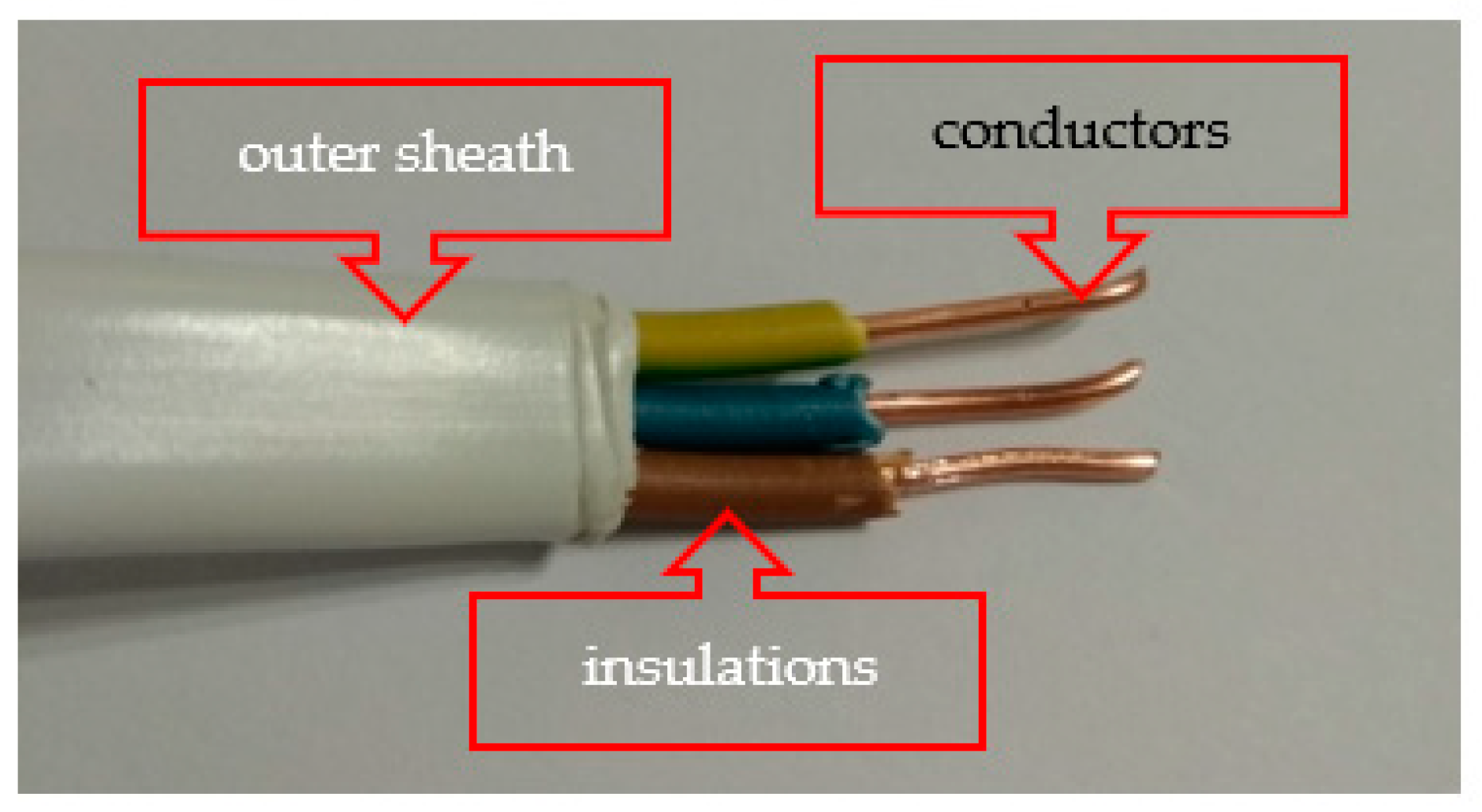
In order to explain the fire behavior of the power PVC-insulated and sheathed cable (Figure 7, Table 2), which was the main component of all electrical installation specimens (No. 1 and 2), an additional test was conducted by means of the standardized method described in EN 50,399 [25] (Figure 8).
The cable was tested inside the chamber as 3.6 m bundled pieces mounted at 4 m in length. A white light smoke detector was used for smoke production determination. A 20.5 kW burner HRR level was used. The heat release parameters were determined indirectly (in the same way as during the SBI tests) by using non-dispersive infrared (NDIR) spectrometers for CO2 concentrations and a paramagnetic analyzer for oxygen depletion (O2). The cable was tested once according to the EN 50,399 standard due to the good repeatability and reproducibility of the test method [21].
The performed experiment showed high values of fire properties of cables as FIGRA, SMOGRA and THR1200s. (Figure 9). The cable was burned completely, and only inorganic filler residue and copper wires were left behind after the test.
The FIGRA parameter (equal to 524 W/s) and THR1200s (equal to 44 MJ) had relatively high values in the cases of heat evolved during the combustion process. The smoke production parameter (SMOGRA) for cables followed the same tendency and was also high and equal to 106 cm2/s2. It was shown that the most effective combustion process occurred during the first stage of burning for about the first 70 s after the flame source action. The maximum FIGRA result was reached after about 400 s after ignition, and then the combustion process slowed down until the specimen was completely burned and extinguished.
The high values of fire parameters obtained during the cable complementary experiment according to EN 50,399 clearly indicated the significant influence of the PVC cable on the flammability of electrical installations.
4.3. Series C—Complementary Experiments of Electrical Installations Connected to the Mains
The electrical installation consisting of five electrical circuits (Figure 10) typical for a residential building connected to the mains was experimentally studied on two types of substrates of opposite combustible properties. This electrical installation was permanently fixed to the substrate as a component of specimen 1 (on the combustible substrate) and specimen 2 (on the non-combustible substrate). The cable (Figure 7) consisted of three copper conductors with a cross-sectional area of 1.5 mm2.
Electrical circuits were made in covers with the following elements:
- -
- cable channels—only circuit No. 1 (PVC)
- -
- electrical conduit rigid pipes on the exposed surface of the specimen (on the front walls) (PVC)
- -
- electrical conduit corrugated pipes between the substrate and backing board, on the rare surface (polypropylene)
- -
- installation without any pipes on the exposed surface of the specimen (on the front walls)
- -
- installation without any pipes on the rare surface between the substrate and backing board
The following equipment and installation equipment were used to make circuits:
- -
- junction box with a diameter of 60 mm—two items (polyethylene and polypropylene)
- -
- one-gang box with diameter of 60 mm—two items
- -
- unipolar key switch, 10 A, 250 V—one item (PVC, melamine)
- -
- single socket 10/16 A, 250 V—two items (PVC, melamine)
- -
- lighting fixture 100 W—one item (ceramic)
- -
- bulb E27 100 W—one item
- -
- coaxial electric power cable YDY 3 × 1.5 mm2—5 m (PVC)
- -
- coaxial electric power cable YDY 3 × 2.5 mm2—10 m (PVC)
- -
- coaxial electric power cable YDY 5 × 2.5 mm2—15 m (PVC)
The specimens of electrical installations were protected by using the following:
- -
- wall switchgear with TH 35 rail, minimum width in modules 8 × 17.5 mm
- -
- unipolar circuit breaker (16 A, 230/400 V, characteristic C)
- -
- unipolar circuit breaker (10 A, 230/400 V, characteristic B)
- -
- four-pole residual current circuit breaker (40 A, 400 V, 30 mA)
The electrical installation specimens (Figure 2) were charged with a rated current of I = 16 A and with an overload current of I = 1.4 × In = 22.4 A for 25 min. The temperature was measured at two points by the means of thermocouples at each of the two sockets for two currents (Table 3) as follows:
- -
- under the uncovered surface of the socket-fixed without the bottom cover and without covering directly on the surface
- -
- under the surface-mounted plug socket shielded—having a bottom cover
After the test, however, no damage to the sample was found, as the sample circuits were made of new elements that had not previously been charged and withstood the increase of temperature for the set time period of 25 min.
The determined temperature profile was shown before the SBI test in two measuring points, placed on the specimen consisting of electrical installations on the combustible substrate. The temperature at point 1 increased much faster than at the other measuring points up to 121.6 °C. This indicated a significant impact of the heating effect towards the uncovered surface socket causing the possibility of easy ignition inside the installation.
The heating rates (Table 3) showed the maxima at the first stage of the experiment. This specific temperature profile indicated that the temperature rise took place quite quickly and then slowed down with the heating. Slightly similar experiments but for single and much simpler electrical circuits were conducted inside an OSB element by Martinka et al. [29]. They reported a much lower maximum temperature rise on the power cable up to 30.1 °C.
5. Discussion and Conclusions
The limit values (thresholds) for euroclasses (Table 4) were used after the CEN classification standard [26].
The criteria given in EN 13501-1 [26] are suitable for classifying electrical installations, which are installed on walls, ceilings or floorings and are an integral part of them from a fire behavioral point of view.
The presented preliminary results confirm that the SBI method is suitable for the evaluation of fire properties of electrical circuit installations and should be supplemented with other reactions to fire tests of electrical installation, mainly cables which are installed in large numbers in buildings. More data are needed to better understand and explain the role of electrical installations in the spread of fire over walls made of combustible materials as well as a fire’s development inside buildings.
The experimental results (Table 5) show that the highest values of total heat released (THR600s) and smoke production (SMOGRA) were obtained for the electrical installation mounted on a combustible substrate (specimen 1), as was expected. This can be compared to the works of other authors but performed only on the cables, for instance by Breulet and Steenhuizen [21], where the fire parameters measured for 2 cable bundles mounted at SBI apparatus were in the range of 0.3 MJ ÷ 24.8 MJ for THR600s and 0 kW/s ÷ 2097 kW/s for FIGRA (no smoke release reported). Hirschler in [22] presented the measured values at large scale tests of cable trays in the range of 2 MJ ÷ 115 MJ for THR and 10 m2/s ÷ 360 m2/s for TSRpeak. Other measured values at large scale tests at horizontal (H) and vertical (V) configurations reported by Grayson et al. [23] were in the range of 54.9 MJ (H) ÷ 460 MJ (V) for THR and 0.100 kW/s (H) ÷ 3.526 kW/s (V) for FIGRA. The results in Table 5 are within the above ranges with the exception of smoke release results, which could not be compared.
Complementary experiments allowed use to explain the fire properties of the PVC-based power cable.
To the authors’ best knowledge, this is the first published study of a circuit electrical installation under internal wall fire conditions conducted with the single burning item (SBI) scenario approach, which confirms the originality and novelty of the described study.
- -
- The presented preliminary results confirm that the SBI method is suitable for the evaluation of electrical installations in terms of the fire safety of buildings. PVC cable channels and installation pipes are usually made of combustible polymeric materials that also need to be fire tested by mean of the cone calorimeter test method. They constitute a significant element from the point of view of fire safety for buildings, consequently increasing the ability of fire spread over walls, ceiling and floorings.
- -
- Fire spread, heat release and smoke production parameters are the significant factors increasing the fire properties of electrical installations and thus the fire properties of entire buildings. A dense smoke rich in solid and liquid species makes evacuation from the fire difficult, and toxic gas fumes cause intoxication and fatality effects to fire victims. As it was shown in the previous studies of the authors [21], there is a significant impact of constructional and material parameters on the fire properties of electric cables. Thus, the replacement of PVC-based electrical cables with halogen-free cables can reduce the fire performance of entire electrical installations and consequently improve the fire safety of entire buildings.
Further studies are necessary in order to obtain more data and to provide a better understanding and explanation of the observed significant influence of electrical installations on the fire spread over combustible walls inside buildings.
Author Contributions
Investigation, conceptualization, formal analysis, resources, methodology, writing—original draft preparation, writing—review and editing, data curation, K.K.-C.; investigation, conceptualization, formal analysis, resources, writing—original draft preparation, writing—review and editing, supervision, J.F.; conceptualization, resources, B.K.P. All authors have read and agreed to the published version of the manuscript.
Funding
This research received no external funding.
Acknowledgments
The authors would like to express thanks to Andrzej Kolbrecki, Emeritus of Instytut Techniki Budowlanej for his meaningful advice and assistance in developing this research.
Conflicts of Interest
The authors declare no conflict of interest.
References
- IET. Wiring rules. J. Inst. Electr. Eng. 1907. [Google Scholar] [CrossRef] [Green Version]
- Bates, B. Safer electrical installations. IEE Rev. 1998, 44, 131–132. [Google Scholar] [CrossRef]
- McClung, L.B.; Hill, D.J. Electrical system design techniques to improve electrical safety. In Proceedings of the 2010 IEEE IAS Electrical Safety Workshop, ESW 2010, Memphis, TN, USA, 1–5 February 2010. [Google Scholar] [CrossRef]
- Tenaga, S.; TNB (Tenaga Nasional Berhad, Distribution Division). Guidelines for Electrical Wiring in Residential Buildings; TNB: Jalan Sultan Ismail, Kuala Lumpur, 2008. Available online: www.st.gov.my (accessed on 1 December 2020).
- Gentile, P.; Mazzaro, M.; Turturici, C. Fire safety criteria in electrical installations design. In Proceedings of the 2017 17th IEEE International Conference on Environment and Electrical Engineering and 2017 1st IEEE Industrial and Commercial Power Systems Europe, EEEIC/I and CPS Europe 2017, Milan, Italy, 6–9 June 2017. [Google Scholar] [CrossRef]
- BS 7671 Requirements for Electrical Installations. Electrical Safety and the Law; Blackwell Science Ltd.: Hoboken, NJ, USA, 2008; pp. 122–174. [Google Scholar] [CrossRef]
- Regulation (EU) No 305/2011 of the European Parliament and of the Council of 9 March 2011 Laying down Harmonized Conditions for the Marketing of Construction Products and Repealing Council Directive 89/106/EEC. Available online: https://eur-lex.europa.eu/legal-content/EN/TXT/?uri=celex%3A32011R0305 (accessed on 1 December 2020).
- Babrauskas, V. Research on electrical fires: The state of the art. Fire Saf. Sci. 2008, 3–18. [Google Scholar] [CrossRef] [Green Version]
- Barros, J.; Diego, R.I. A review of measurement and analysis of electric power quality on shipboard power system networks. Renew. Sustain. Energy Rev. 2016, 62, 665–672. [Google Scholar] [CrossRef]
- Backstrom, R.; Dini, D. Firefighter safety and photovoltaic installations research project. Reliab. Photovolt. Cells Modul. Compon. Syst. V 2012, 8472. [Google Scholar] [CrossRef]
- Falvo, M.C.; Capparella, S. Safety issues in PV systems: Design choices for a secure fault detection and for preventing fire risk. Case Stud. Fire Saf. 2015, 3, 1–16. [Google Scholar] [CrossRef] [Green Version]
- Manzini, G.; Gramazio, P.; Guastella, S.; Liciotti, C.; Baffoni, G.L. The fire risk in photovoltaic installations—Checking the PV modules safety in case of fire. Energy Procedia 2015, 81, 665–672. [Google Scholar] [CrossRef] [Green Version]
- Plumecocq, W.; Coutin, M.; Melis, S.; Rigollet, L. Characterization of closed-doors electrical cabinet fires in compartments. Fire Saf. J. 2011, 46, 243–253. [Google Scholar] [CrossRef]
- Huang, L.C.; Chang, H.C.; Chen, C.C.; Kuo, C.C. A ZigBee-based monitoring and protection system for building electrical safety. Energy Build. 2011, 43, 1418–1426. [Google Scholar] [CrossRef]
- Novak, C.J.; Stoliarov, S.I.; Keller, M.R.; Quintiere, J.G. An analysis of heat flux induced arc formation in a residential electrical cable. Fire Saf. J. 2013, 55, 61–68. [Google Scholar] [CrossRef]
- Van Hees, P.; Axelsson, J.; Green, A.; Grayson, S. Mathematical modelling of fire development in cable installations. Fire Mater. 2001, 25, 169–178. [Google Scholar] [CrossRef]
- Janssens, M.L.; Turner, S.; Tsuchino, S. THIEF model evaluation for cables used in nuclear plants in Japan. Procedia Eng. 2013, 62, 829–836. [Google Scholar] [CrossRef] [Green Version]
- Matsuda, A. Fire Safety Simulation of Cable Fire in Nuclear Power Plant Room Based on Flammability Database of Cables. Transactions, SMiRT-23 Manchester, United Kingdom—10–14 August 2015, Division III, Paper ID 514 (Applied Computation Simulation and Animation). Available online: https://repository.lib.ncsu.edu/bitstream/handle/1840.20/33919/SMiRT-23_Paper_514.pdf?sequence=1-23_Paper_514.pdf?sequence=1&isAllowed=y (accessed on 1 December 2020).
- Kaczorek-Chrobak, K.; Fangrat, J. Influence of constructional-material parameters on the fire properties of electric cables. Energies 2019, 12, 4569. [Google Scholar] [CrossRef] [Green Version]
- Kaczorek-Chrobak, K.; Fangrat, J. PVC-based copper electric wires under various fire conditions: Toxicity of fire effluents. Materials 2020, 13, 1111. [Google Scholar] [CrossRef] [PubMed] [Green Version]
- Breulet, H.; Steenhuizen, T. Fire testing of cables: Comparison of SBI with FIPEC/Europacable tests. Polym. Degrad. Stab. 2005, 88, 150–158. [Google Scholar] [CrossRef]
- Hirschler, M.M. Comparison of large- and small-scale heat release tests with electrical cables. Fire Mater. 1994, 18, 61–76. [Google Scholar] [CrossRef]
- Grayson, S.J.; Van Hees, P.; Green, A.M.; Breulet, H.; Vercellott, U. Assessing the fire performance of electric cables (FIPEC). Fire Mater. 2001, 25, 49–60. [Google Scholar] [CrossRef]
- Fangrat, J. Combustibility of building products versus fire safety. Bull. Pol. Acad. Sci. Tech. Sci. 2016, 64, 4. Available online: https://www.degruyter.com/view/j/bpasts.2016.64.issue-4/issue-files/bpasts.2016.64.issue-4.xml (accessed on 1 December 2020).
- EN 13501-6:2018. Fire Classification of Construction Products and Building Elements—Part 6: Classification Using Data from rEaction to Fire Tests on Power, Control and Communication Cables; CEN: Brussels, Belgium, 2018. [Google Scholar]
- EN 13501-1:2019. Fire Classification of Construction Products and Building Elements—Part 1: Classification Using Data from Reaction to Fire Tests; CEN: Brussels, Belgium, 2019. [Google Scholar]
- EN 13823:2010+A1:2014. Reaction to Fire Tests of Building Products—Building Products Excluding Floorings Exposed to the Thermal Attack by a Single Burning Item; CEN: Brussels, Belgium, 2010. [Google Scholar]
- EN 50399:2011/A1:2016. Common Test Methods for Cables under Fire Conditions—Heat Release and Smoke Production Measurement on Cables during Flame Spread Test—Test Apparatus, Procedures, Results; CEN: Brussels, Belgium, 2011. [Google Scholar]
- Martinka, J.; Rantuch, P.; Štefko, T.; Wachter, I. Electric Cables Installed in OSB Boards Surfaces and Their Temperature. In WFS 2020: Wood & Fire Safety; Makovicka Osvaldova, L., Markert, F., Zelinka, S., Eds.; Springer: Cham, Switzerland, 2020; pp. 426–431. [Google Scholar] [CrossRef]
Figure 1.
Scheme of single burning item (SBI) set up based on EN 13,823 [27]. Left side: 1,3—visual observations, 2—fixed frame, 4—trolley; right side: 5—boards covering the edges, 6—borders of the burner heating zone, 7—ignition source (burner).
Figure 1.
Scheme of single burning item (SBI) set up based on EN 13,823 [27]. Left side: 1,3—visual observations, 2—fixed frame, 4—trolley; right side: 5—boards covering the edges, 6—borders of the burner heating zone, 7—ignition source (burner).

Figure 2.
Overview diagram of SBI specimen with electrical installation as a component of specimen 1 (on a combustible substrate) and specimen 2 (on a non-combustible substrate).
Figure 2.
Overview diagram of SBI specimen with electrical installation as a component of specimen 1 (on a combustible substrate) and specimen 2 (on a non-combustible substrate).

Figure 3.
View of specimens at SBI test apparatus—electrical installation on the combustible substrate (specimen 1) and non-combustible substrate, e.g., calcium-silicate board (specimen 2): (a) before the test, (b) during the test, (c) after the test.
Figure 3.
View of specimens at SBI test apparatus—electrical installation on the combustible substrate (specimen 1) and non-combustible substrate, e.g., calcium-silicate board (specimen 2): (a) before the test, (b) during the test, (c) after the test.

Figure 4.
The comparison of the fire grown rate (FIGRA0.2MJ) results as a function of time at the SBI test.
Figure 4.
The comparison of the fire grown rate (FIGRA0.2MJ) results as a function of time at the SBI test.

Figure 5.
Smoke production rate (SMOGRA) results as a function of time of the test.

Figure 6.
Total heat release (THR600s) results as a function of time of the test.

Figure 7.
PVC-insulated and sheathed copper cable, which was the main component of all electrical installation specimens.
Figure 7.
PVC-insulated and sheathed copper cable, which was the main component of all electrical installation specimens.

Figure 8.
Schematic of test equipment in accordance with the EN 50,399 standard [28]; 1—chamber, 2—hood, 3—exhaust duct, 4—bidirectional probe, 5—sampling probe, 6—smoke measuring equipment, 7—guide vanes, 8—extracting ventilator, 9—smoke outlet, 10—ladder, 11—test chamber, 12—cables testes, 13—door, 14—burner, 15—air inlet duct, 16—air inlet box, 17—pressure transducer, 18—gas sampling line, 19—O2 and CO2 analyzers.

Figure 9.
Heat release and smoke production results for PVC-insulated and sheathed coaxial cable.

Figure 10.
Scheme of electrical circuits of tested samples.


Table 1.
Composition of electrical installation components.
| Specimen Components | Composition |
|---|---|
| lighting fixture (lamp) with bulb | ceramic/glass |
| sockets, key switch | poly(vinyl chloride), melamine |
| installation conduit rigid pipes on the exposed surface, cable channels | poly(vinyl chloride) |
| installation conduit corrugated pipes | polypropylene |
| junction box, one-gang box | polyethylene/polypropylene |
| cables (YDYp 3 × 1.5 mm2, YDYp 3 × 2.5 mm2, YDYp 5 × 2.5 mm2) | copper, poly(vinyl chloride) sheathed and insulated |
Table 2.
Characteristics of tested coaxial power cable.
| Cable Size | Cable Dimensions, mm × mm | Weight of Cable, kg/km | Conductors | Insulations | Outer Sheath |
|---|---|---|---|---|---|
| 3 × 1.5 mm2 | 3.8 × 8.5 | 76 | Copper, round, 43.2%w | poly(vinyl chloride), 14.3%w | poly(vinyl chloride), 42.5%w |
Table 3.
Temperature measurements T (°C): columns (2), (4) under uncovered surface socket (measuring point 1, (3), (5) under covered surface-mounted socket (measuring point 2), with the load circuit current 16 A or 22.4, A respectively. Relevant increase of temperature is shown in columns (6), (8) and (7), (9).
| t, min | T, °C | ∆T, °C/min | ||||||
|---|---|---|---|---|---|---|---|---|
| 16 A | 22.4 A | 16 A | 22.4 A | |||||
| (1) | (2) | (3) | (4) | (5) | (6) | (7) | (8) | (9) |
| 0 | ||||||||
| 1 | 23.5 | 24 | 25.5 | 25.5 | - | - | - | - |
| 2 | 24.2 | 24.5 | 26.7 | 26.1 | 0.7 | 0.5 | 1.2 | 0.6 |
| 3 | 25.3 | 25.7 | 31.1 | 27.5 | 1.1 | 1.2 | 4.4 | 1.4 |
| 4 | 27.3 | 27.4 | 37.3 | 29.7 | 2.0 | 1.7 | 6.2 | 2.2 |
| 5 | 29.7 | 29.4 | 44 | 32.6 | 2.4 | 2.0 | 6.7 | 2.9 |
| 6 | 32.3 | 31.5 | 50.7 | 36.1 | 2.6 | 2.1 | 6.7 | 3.5 |
| 7 | 35.1 | 33.5 | 57 | 39.6 | 2.8 | 2.0 | 6.3 | 3.5 |
| 8 | 38 | 35.5 | 64 | 42.6 | 2.9 | 2.0 | 7.0 | 3.0 |
| 9 | 41.2 | 37.3 | 68.4 | 45.9 | 3.2 | 1.8 | 4.4 | 3.3 |
| 10 | 43.6 | 39.2 | 73.9 | 49.2 | 2.4 | 1.9 | 5.5 | 3.3 |
| 11 | 46.3 | 41 | 79.2 | 52.5 | 2.7 | 1.8 | 5.3 | 3.3 |
| 12 | 48.8 | 42.7 | 83.6 | 55.5 | 2.5 | 1.7 | 4.4 | 3.0 |
| 13 | 51.2 | 44.3 | 88 | 58.4 | 2.4 | 1.6 | 4.4 | 2.9 |
| 14 | 53.5 | 45.8 | 92.5 | 61.2 | 2.3 | 1.5 | 4.5 | 2.8 |
| 15 | 55.7 | 47.2 | 96.2 | 63.9 | 2.2 | 1.4 | 3.7 | 2.7 |
| 16 | 57.8 | 48.6 | 99.8 | 66.3 | 2.1 | 1.4 | 3.6 | 2.4 |
| 17 | 59.7 | 49.9 | 103.2 | 68.7 | 1.9 | 1.3 | 3.4 | 2.4 |
| 18 | 61.6 | 51.1 | 106.3 | 70.8 | 1.9 | 1.2 | 3.1 | 2.1 |
| 19 | 63.4 | 52.3 | 109.3 | 72.8 | 1.8 | 1.2 | 3.0 | 2.0 |
| 20 | 65.1 | 53.4 | 112 | 74.8 | 1.7 | 1.1 | 2.7 | 2.0 |
| 21 | 66.8 | 54.5 | 114.6 | 76.4 | 1.7 | 1.1 | 2.6 | 1.6 |
| 22 | 68.3 | 55.5 | 117.2 | 78.1 | 1.5 | 1.0 | 2.6 | 1.7 |
| 23 | 69.8 | 56.5 | 119.6 | 79.6 | 1.5 | 1.0 | 2.4 | 1.5 |
| 24 | 71.1 | 57.5 | 121.6 | 81.2 | 1.3 | 1.0 | 2.0 | 1.6 |
Table 4.
Threshold values for SBI test in the euroclasses system [26].
Table 4.
Threshold values for SBI test in the euroclasses system [26].
| Class | Parameter |
|---|---|
| A2 and B | FIGRA0.2MJ ≤ 120 W/s THR600s ≤ 7.5 MJ LFS < edge of the specimen |
| C | FIGRA0.2MJ ≤ 250 W/s THR600s ≤ 15 MJ LFS < edge of the specimen |
| D | FIGRA0.4MJ ≤ 750 W/s |
Table 5.
Summary of the experimental results obtained by the means of SBI test method [25,26]; specimens are described in Section 4.1.2.
Table 5.
Summary of the experimental results obtained by the means of SBI test method [25,26]; specimens are described in Section 4.1.2.
| No | FIGRA0.2MJ;0.4MJ W/s | SMOGRA cm2/s2 | THR600s MJ | Reaction to Fire Class |
|---|---|---|---|---|
| 1 | 1062 | 39 | 66.8 | E or F |
| 2 | 0.0 | 29 | 0.1 | A2 |
| 3 | 376 | 28 | 27.8 | D |
| 4 | 0.0 | 0.0 | 0.5 | A1 or A2 |
Publisher’s Note: MDPI stays neutral with regard to jurisdictional claims in published maps and institutional affiliations. |
© 2020 by the authors. Licensee MDPI, Basel, Switzerland. This article is an open access article distributed under the terms and conditions of the Creative Commons Attribution (CC BY) license (http://creativecommons.org/licenses/by/4.0/).
Share and Cite
MDPI and ACS Style
Fangrat, J.; Kaczorek-Chrobak, K.; Papis, B.K. Fire Behavior of Electrical Installations in Buildings. Energies 2020, 13, 6433. https://doi.org/10.3390/en13236433
AMA Style
Fangrat J, Kaczorek-Chrobak K, Papis BK. Fire Behavior of Electrical Installations in Buildings. Energies. 2020; 13(23):6433. https://doi.org/10.3390/en13236433
Chicago/Turabian StyleFangrat, Jadwiga, Katarzyna Kaczorek-Chrobak, and Bartłomiej K. Papis. 2020. "Fire Behavior of Electrical Installations in Buildings" Energies 13, no. 23: 6433. https://doi.org/10.3390/en13236433
Note that from the first issue of 2016, this journal uses article numbers instead of page numbers. See further details here.