Current State and Future Prospects for Electrochemical Energy Storage and Conversion Systems


1
Centre for Materials Physics, Department of Physics, Durham University, Durham DH1 3LE, UK
2
School of Computing, Engineering and Physical Sciences, University of the West of Scotland, Paisley PA1 2BE, UK
3
Faculty of Chemistry and Chemical Technology, Al-Farabi Kazakh National University, Al-Farabi Avenue, 71, Almaty 050040, Kazakhstan
4
Clean Energy Research Lab (CERL), Department of Physics, COMSATS University Islamabad, Lahore 54000, Pakistan
*
Author to whom correspondence should be addressed.
Energies 2020, 13(21), 5847; https://doi.org/10.3390/en13215847
Submission received: 30 September 2020
/
Revised: 22 October 2020
/
Accepted: 26 October 2020
/
Published: 9 November 2020
(This article belongs to the Special Issue High Energy Electrochemical Capacitors)
Abstract
:Electrochemical energy storage and conversion systems such as electrochemical capacitors, batteries and fuel cells are considered as the most important technologies proposing environmentally friendly and sustainable solutions to address rapidly growing global energy demands and environmental concerns. Their commercial applications individually or in combination of two or more devices are based on their distinguishing properties e.g., energy/power densities, cyclability and efficiencies. In this review article, we have discussed some of the major electrochemical energy storage and conversion systems and encapsulated their technological advancement in recent years. Fundamental working principles and material compositions of various components such as electrodes and electrolytes have also been discussed. Furthermore, future challenges and perspectives for the applications of these technologies are discussed.
1. Introduction
The enormous growth in world population, particularly in the developing world, coupled with technological developments are considered as the key factors behind the immense increase in electrical energy consumption over the past half century. Further increases in the world energy consumption are expected with its energy demand projected to be doubled by the middle and tripled by the end of the century [1] as a result of further population growth (with world population expected to reach 9 billion by 2048) and increased electrical energy demands in industrial and commercial sectors [2]. Currently, fossil fuels such as oil, gas and coal are the primary sources of energy, with more than 85% of the world’s total energy generation achieved through these conventional sources [3]. Over-reliance on fossil fuels for production of energy has led to numerous environmental challenges including poor air quality, unexpected climatic variations, water/soil contamination and a colossal increase in greenhouse gas emissions [4,5]. To contain or reverse these trends, deployment of more sustainable and low carbon or even carbon free renewable sources of energy such as wind, solar or tidal are essential. However, these renewable sources of energy are location- specific and, in some cases unpredictable in nature and therefore operational flexibility is key for their integration into the power systems. This flexibility is attainable when using appropriate energy storage technologies that can help in managing fluctuations and mismatches in energy supply and demands, ultimately improving the efficiencies in energy and power supply systems by reducing the gap between production and consumption. Furthermore, growth in energy proportion added to national grid through the integration of renewable sources such as wind and solar results in curtailments which can be addressed by using appropriate storage technologies [6]. There are a broad range of energy storage and conversion technologies available including chemical, thermochemical, mechanical, electrical and electrochemical storage systems. Among these, electrochemical energy storage and conversion systems such as electrochemical capacitors/batteries and fuel cells respectively, have received the most intensive attention and have been adopted in everyday applications due to their high columbic efficiencies. Basically energy storage devices perform two important tasks-(a) time shifting bulk energy from renewables production to time of energy demand (supplied by batteries + fuel cells) (b) production of clean, stable power and frequency, avoiding voltage spikes (important for digital economy) by supercapacitors and high power batteries. However, challenges related to their durability, high cost, environmental concerns, and operability problems must be addressed in order to improve their effectiveness and further increase uptake. For instance, even though lithium-ion batteries have transformed the technology of electric vehicles (EV) and portable electronics such as mobile phones and laptops, this technology still suffers from issues such as high lithium cost and safety concerns [7]. In 2011, almost 78% of lithium was extracted from brines (in Chile, Argentina and USA), and the rest came from hard rock mines (in China and Australia) [8]. Environmental impact of lithium mining including human health, effect on biodiversity and availability of clean/fresh water for consumption and agriculture use are other key concerns. Since major lithium reserves are located in salt lakes and pans where lithium is extracted through evaporation and flooding of reserves with fresh water [9]. Similarly, electrochemical capacitors (ECs) have inferior energy densities whereas fuel cells have operability and system issues [10,11].
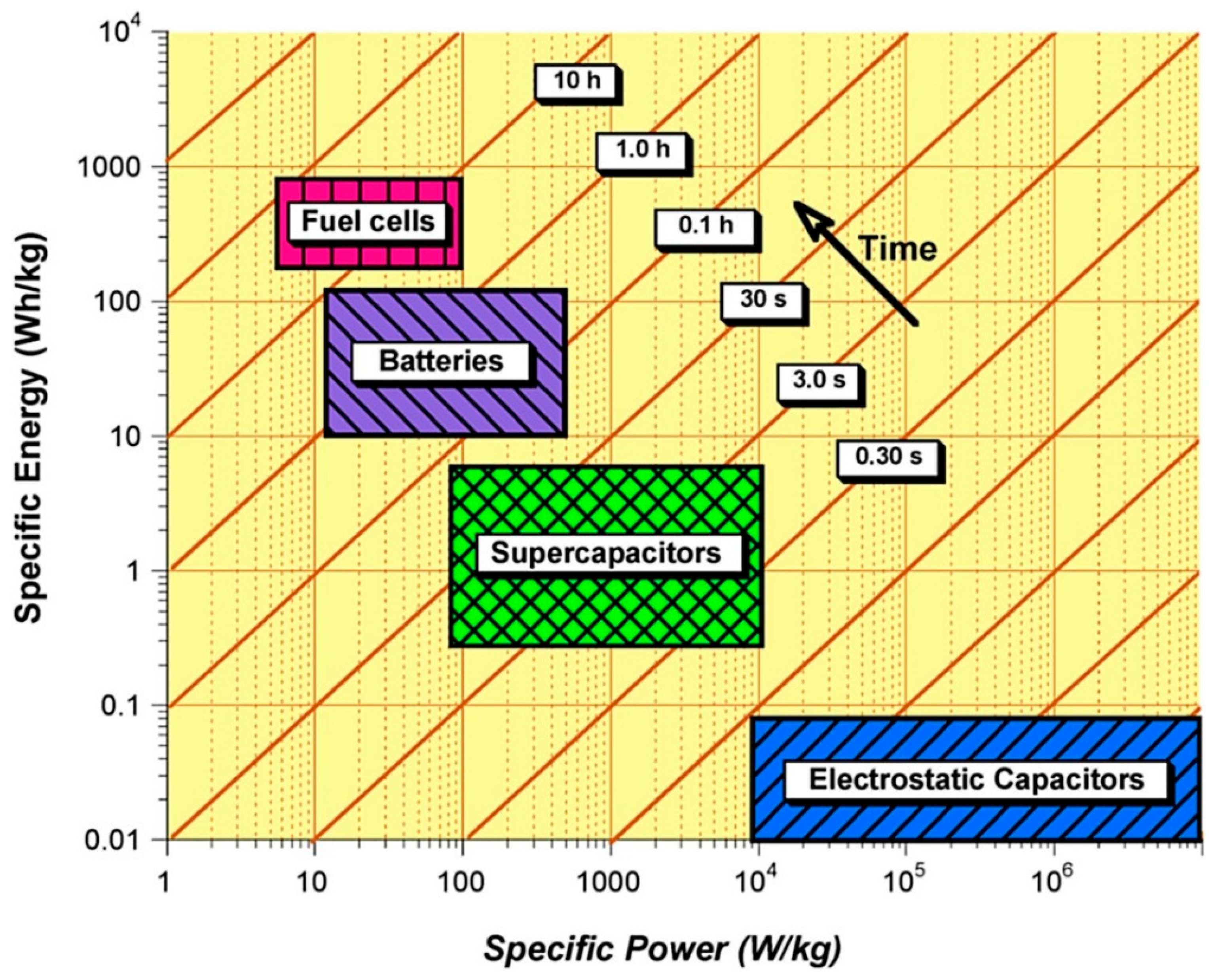
The aim of this review is to make comprehensive classification of electrochemical energy storage, conversion systems as shown in Figure 1, explain their basic working principles, and technical characteristics, highlight the distinctive properties of each system, and discuss their fields of application. A diverse range of energy storage and conversion devices is shown in Figure 1 based on their energy delivery time varying with the type of mechanism involved in energy storage or conversion systems. For example, electrochemical capacitors are considered as high power density devices and their delivery time is in the range of few seconds to minutes since these devices utilise only the material on the electrode surface unlike batteries or fuel cells where bulk of the material is involved in energy storage and conversion respectively. Other characteristics of these devices vary as well due to the fundamental difference in the mode of energy storage or conversion (physical/electrochemical). In case of electrochemical capacitors, most of the commercially used devices use electric double layer charge storage phenomenon, which results in inferior energy densities as compared to other electrochemical energy storage or conversion devices shown in Figure 2.
However, benefits of interfacial charge storage include better cyclability, efficiency and long cycle life. Whereas, in case electrochemical batteries and fuel cell electronic charge transfer occurring through bulk of the material results in superior energy densities nevertheless, these devices suffer from degradation and poorer cyclability when compared with electrochemical capacitors.
2. Electrochemical Energy Storage and Conversion Systems
Electrochemical capacitors/batteries and fuel cells are key electrochemical energy storage and conversion technologies respectively, used in commercial applications with their particular selection dependent on performance limitations such as energy densities, power densities, and cycle life.
Electrochemical batteries and fuel cells are considered as high energy density devices with typical gravimetric energy densities in the range of 100–200 Wh kg−1 and 600–1200 Wh kg−1 respectively, whereas current ECs have significantly lower energy densities with typical values typically between 0.05–30 Wh kg−1 [12]. However, ECs are considered as high-power density devices with very short charge/discharge times (of the order of seconds) which is difficult to achieve by other electrochemical energy storage and conversion devices. Figure 2 shows a comparison of specific energy, specific power and their delivery timescale for different energy storage and conversion devices. At present, none of these devices has the capability to meet the wide spectrum of requirements demanded by the diverse range of renewable energy sources such as wind, tidal and solar. However, they can respond to a broad rang requirements such as fast charge/discharge, peak power demands and high energy storage needs over a longer period of time when used in a combination of two or more.
2.1. Electrochemical Capacitors
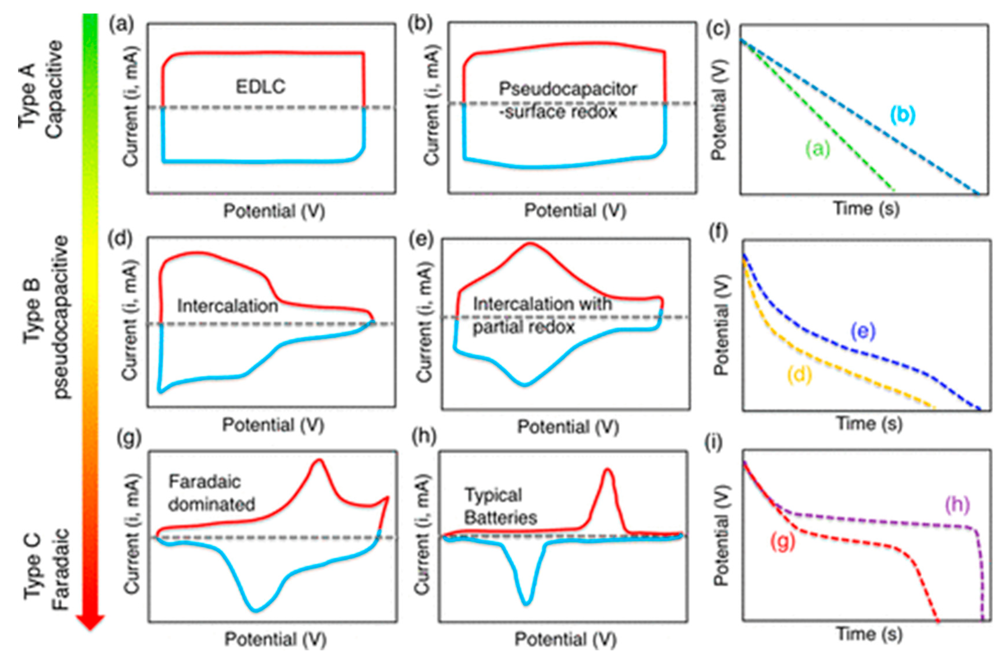
Electrochemical capacitors (ECs), also known as supercapacitors (SCs) or ultra-capacitors (UCs), are electrochemical energy storage devices having energy densities (EDs) higher than electrostatic capacitors but lower than electrochemical batteries, as shown in Figure 2. ECs can bridge the energy gap in the range of 10−2 to 10 Wh kg−1 between electrochemical batteries and electrostatic capacitors as shown in Figure 2. Their other distinctive properties include high power densities, remarkably long cycle life and good capacity retention. According to their charge storage mechanism, ECs can be further classified into three categories of electric double layer capacitors (EDLCs), pseudo-capacitors (PCs) and hybrid capacitors (HCs). Electric double layer capacitors (EDLCs) store electric energy by storing electric charge through the formation of an electric double layer at the electrode/electrolyte interface upon polarization, where their capacitance is substantially higher than the capacitance of a conventional electrostatic capacitor due to very high specific surface areas and charge separation of only a few Ångstroms. In the case of ideal electric double layer behaviour, cyclic voltammograms are rectangular in shape with a voltage independent current and linear charge/discharge curves as shown in Figure 3a–c [14]. Capacitor-like behaviour involving electrochemical, rather than physical, charge storage has been demonstrated in so-called pseudo-capacitive materials in ECs, initially by Conway [15] which occupies the middle ground between EDLCs and battery like capacitor as shown in Figure 3d–f. Pseudo-capacitive charge storage benefits from voltage-dependent electrochemical electronic transfer, which is known as Faradic charge storage and is similar to that of battery storage, whereas, hybrid capacitors involve both physical and chemical (battery-like) charge storage mechanisms (with noticeable and separated peaks associated with the reduction and oxidation) as shown in Figure 3g,h. The charge/discharge behaviour of batteries/battery like capacitors is non-linear and symbolised by plateaus of nearly constant potential corresponding to the potentials at which the Faradaic reduction or oxidation occurs as shown in Figure 3i [16,17]. The charge storage mechanisms and operating principles of these three main classes of supercapacitor is discussed in detail below.
2.1.1. Electric Double Layer Capacitors (EDLCs)
In electric double layer capacitors, a double layer is formed near or at the surface of each electrode due to electrostatic interactions without any electronic transfer between electrode/electrolyte ions at the interface.
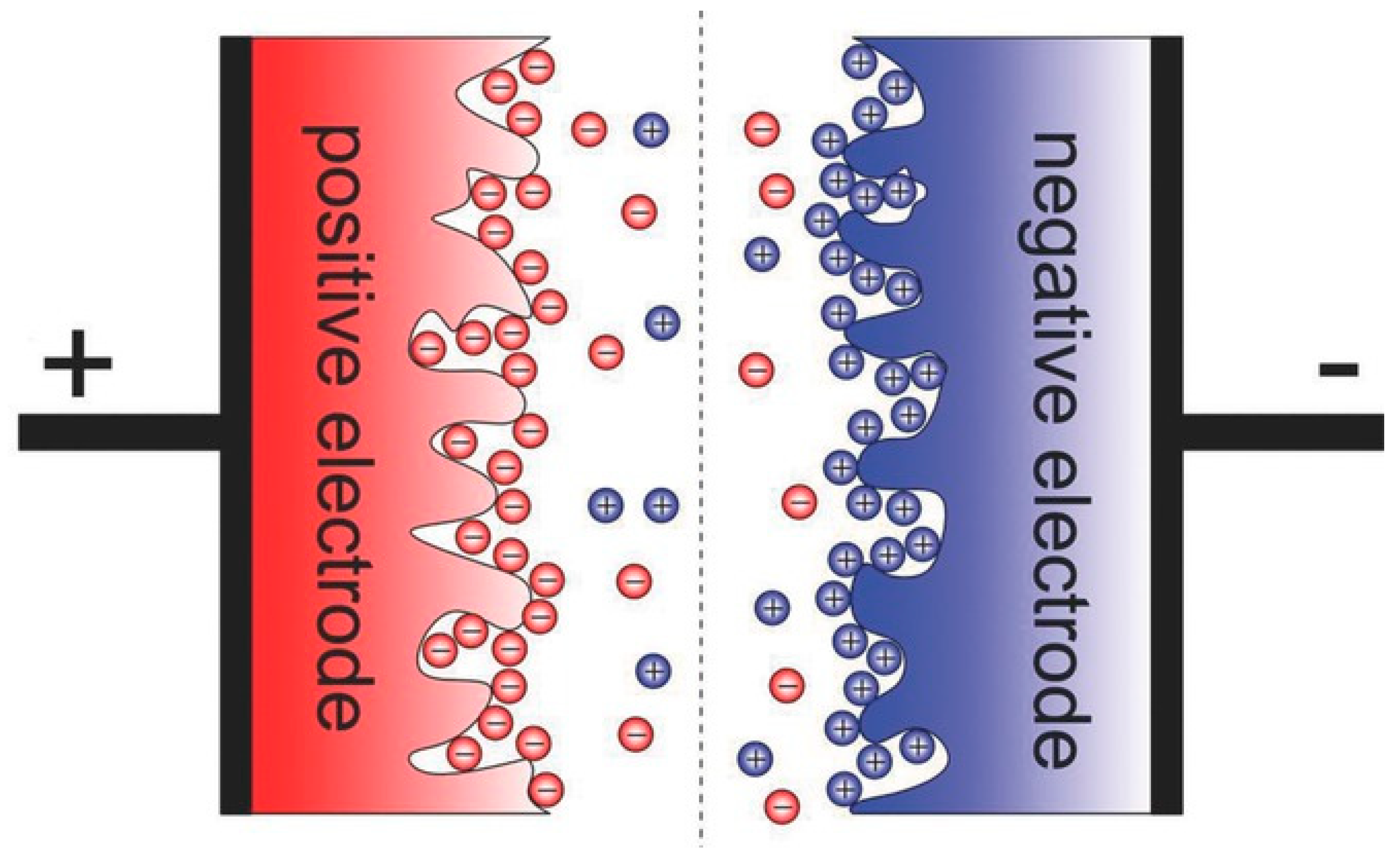
This electrostatic charge accumulation is non-Faradic and is identical in nature to that of electrostatic capacitor since there is no transportation of charge between electrode and electrolyte. After the application of voltage, charge is accumulated on the electrode surface where ions of the opposite charges diffuse into the pore of active material with opposite charge. An electric double layer is formed at the interface since electrodes are engineered in such a way to prevent the recombination of ions. This physical charge storage on very high specific surface area of active materials where charges are separated by very small distance of the order of nano-meters results in very high specific capacitance and exceptionally high cyclability. If ES1 and ES2 are the electrode surface, A− anion, C+ is cation and interface is represented by //, then interfacial electrochemical reaction can be expressed by the following equations [18]:
On one electrode:
On other electrode:
Complete reaction [charge/discharge]:
The structure of the electric double layer on a porous electrode is shown in Figure 4.
The specific surface area and average pore size of the active material are key parameters playing an important role in the capacitive performance of EDLC which can be seen by considering the simple expression for a parallel plate capacitor, Equation (7):
where A is the surface area of the capacitor, d is the separation of the electrodes and ε is the permittivity of the dielectric occupying the space between the electrodes.
Optimised pore size, high specific surface area, good conductivity and inertness are the basic requirements for the selection of electrode materials. Carbon based electrode materials in a wide variety of shapes and forms have been used in electrochemical capacitors, however, the most commonly used active electrode materials in ELDCs are graphene, carbon nanotubes, activated carbon and carbon aerogels. Carbon based materials are preferred choice due to their unique properties such as high surface area, tunable pore size, ease of process-ability, excellent electronic conductivity and nontoxicity.
Activated carbon is the most commonly used carbon electrode material commercially for ECs. However, due to the surface charge storage, the specific capacitance of carbon-based materials is limited and is in the range of 200–300 Fg−1, which is one of the main reasons behind the inferior energy densities which restrict their wider use in commercial applications. By improving the pore structure of the active material (high specific surface area and pore optimization) high specific capacitance can be realistically achieved. Recently, Kesavan and co-workers reported a specific capacitance of 381 Fg−1 at a current density of 1.7 Ag−1, using a biomass-derived nanoporous activated carbon as the active material, with an impressive 95% capacity retention after 6000 cycles using 1.0 M H2SO4 aqueous solution as the electrolyte. Kesavan and co-workers were able to achieve an energy density of 47.1 Wh kg−1 and a power density of 22.6 kW kg−1, one of the highest reported energy density for these type of materials achieved due to the hierarchical porous structure obtained after physical activation of bio-derived food waste based carbon [20]. Numerous other approaches, such as using a redox-active electrolyte have been adopted to enhance the performance of EDLCs. An exceptionally high specific capacitance of 885 Fg−1 was attained by introducing 0.05 M FeBr3 into 0.5MNa2SO4 solution as a redox active additive resulting in a specific capacitance four times higher than the specific capacitance of 204 Fg−1 measured without the redox additive [21]. Other approaches for increasing the specific capacitance of EDLCs, such as the introduction of pseudo-capacitive materials (i.e., metal oxides) or functional groups into the carbon matrix or on its surface, have also been investigated recently will be discussed in the following sections.
2.1.2. Pseudo-Capacitors (PCs)
Electrochemical capacitors, particularly EDLCs, have significantly lower energy densities when compared with electrochemical batteries such as the extensively commercialised lithium-ion batteries. Two common approaches can be implemented to enhance the energy density of supercapacitors: by increasing their operating voltages or by introducing new highly capacitive electrodes. The former generally results in lower power densities since the non-aqueous electrolytes such as organic or ionic liquids used to sustain the operating voltage of the device above about 1 V, are more resistive in nature than aqueous electrolytes. while, the latter is considered rather more promising where specific capacitance is enhanced pseudocapacitively, improving the energy density given by Equation (8) whilst retaining high power densities:
where ‘E’ is the energy density in Wh kg−1, ‘C’ is the capacitance in Farads and ‘V’ is the operating voltage in Volts.
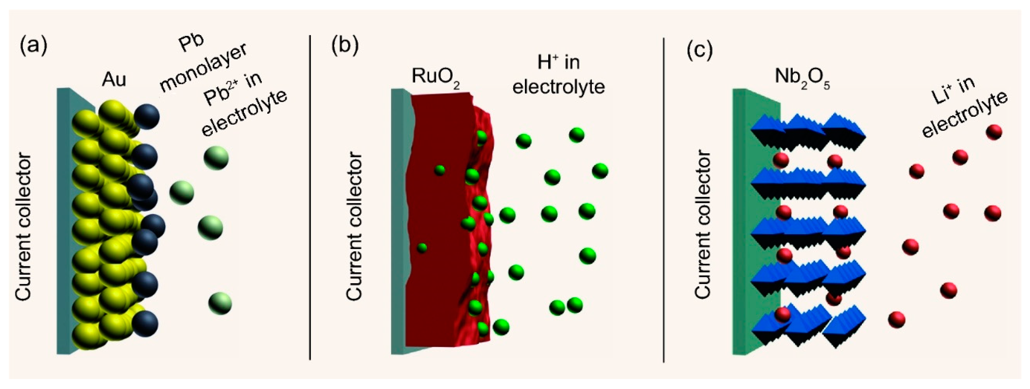
Unlike EDLCs, PCs exhibit a superior capacitive performance where metal oxide (MOs) or conducting polymers (CPs) are commonly used as an active material. The total capacitance of a pseudocapacitor is the sum of both the electric double layer component at the interface between the electrode and electrolyte and a pseudocapacitive contribution through electronic charge transfer [22,23]. The energy storage mechanism underpinning pseudocapacitance is based on fast and highly reversible redox reactions where electron transfer occurs to and from reactants adsorbed at the electrode surface or from reactant solution. Pseudocapacitance charge storage can be further categoriesed into three different charge storage mechanisms (a) under-potential deposition, (b) redox pseudocapacitance and (c) intercalation pseudocapacitance, as shown in Figure 5 [24].
Conductive polymers commonly used as active material in ECs include polypyrrole (PPY), polythiophene (PT), and polyaniline (PANI). Conducting polymer-based materials have not been explored extensively since their specific capacitance-typically in the range of 80–190 Fg−1 [25,26]-is quite low. In contrast, metal oxide based materials exhibit substantially higher capacitive performance, with specific capacitance reaching around 1500 Fg−1 for ruthenium oxides [27].
The extraordinary properties of ruthenium oxide, such as high theoretical specific capacitance (1400–2000 Fg−1), good electrical conductivity, large surface area and excellent power densities due to interconnected channels have resulted in the exceptional performance of electrodes based on this material. However, the cost of RuO2 is very high, since ruthenium is one of the rarest metals, which makes it unviable for commercial applications. Other metal oxides, such as nickel oxide (NiO) [28] cobalt oxide (Co3O4) [29] and manganese dioxide (MnO2) [30] have demonstrated pseudocapacitance, with MnO2 being the most investigated due it its excellent capacitive performance, cost-effectiveness and wide availability. Despite the promise of their high capacitances, the commercial use of metal oxide pseudocapacitive materials is hindered by shortcomings such high resistivity (with the exception of ruthenium oxide), high cost and poor cyclability (since the redox reaction is not completely reversible).
2.1.3. Hybrid-Capacitors (HCs)
As discussed above EDLCs have superior power densities (PDs) whereas to PCs have relatively higher energy densities (EDs). In order to benefit from both the high EDs and PDs of PCs and EDLCs, respectively a new type of electrochemical capacitors has been developed where the supercapacitor cell consists of a combination of a pseudocapacitive electrode (at which faradic processes occur) and EDL-capacitor like electrode (where charge storage is non-Faradic) [31], as shown in Figure 6.
The Faradic electrode normally consists of metal oxides (MOs) or conducting polymers (CPs) exhibiting high specific capacitance and so contributing towards higher EDs, whereas the non-Faradic electrode commonly consists of carbon-based material providing outstanding PDs. Additional motivations behind the development of hybrid electrode systems include excellent cyclability, improved cost-effectiveness, enhanced reaction kinetics and exhibiting higher energy densities while maintaining outstanding power densities [33]. Hybrid capacitors can be divided into three categories according to their electrode configuration: i.e., asymmetric hybrid, composite hybrid and battery-type hybrid capacitors [34]. The key object of the development of HCs is to improve energy densities of supercapacitors to fill the energy gap between batteries and conventional capacitors and bring them closer to electrochemical batteries. A study by Peifeng, et al. developed a zinc-ion hybrid supercapacitor by producing zinc/carbon composites using a well-connected high specific surface area (SSA) fine-tuned hierarchical porous architecture where the well-engineered architect provided active sites for the zinc-ion storage resulting in an excellent energy density of 118 Wh kg-1 and outstanding cycling stability of over 94.9% after 20,000 cycles [35]. An alternative approach to produce HCs with high capacitive performance is by using composites of more than two active materials. A study by Wei et al. employed CNT/Co3S4@NiCo layered double hydroxide (LDH) ternary nanocomposites as the active material in a battery-type hybrid cell which possessed a SC of 774 Fg−1 at a current density of 1 Ag−1. This cell structure was also able to achieve an energy density of 60 Wh kg−1 at a power density of 1507 W kg-1 [36].
The future direction of research for HCs necessitates to improve reaction kinetics of anode and cathode to maintain high PDs since pseudo-capacitive component of HC cell results in higher ESR. Also, advancements in carbonaceous cathode materials (synthesis of new martials and controlling their porosity) is essential to enhance their capacitive performance further to improve their contribution towards higher EDs.
3. Comparison of Different Types of ECs
Table 1 shows the material selection criteria and performance parameters for different electrochemical capacitor types.
Among SAs discussed above, EDLCs are the best performing devices in terms of power densities but they suffer from low energy densities when compared with PCs or HCs. The development of novel materials and new types of supercapacitor devices such HCs (symmetric, asymmetric and battery type) has potentially opened up new routes to address some of the deficiencies of EDLCs. However, these new generation devices are at their initial stages of development and require substantial further R&D efforts to respond to required energy/power densities in a wide range of practical applications. In particular, the following areas of research need further exploration to improve performance of electrochemical capacitors:
- Synthesis of novel and better-quality materials (both electrode and electrolyte) to enhance performance and reduce cost.
- Development of hierarchical porous microstructures in order to maintain high power densities while improving the energy densities and avoiding the creation of inaccessible specific surface area.
- Improved understanding of energy storage mechanisms due to interfacial reactions at the electrode/electrode interface.
- Improvements to the interfacial interactions between electrolyte ions and electroactive material through surface modification.
3.1. Electrochemical Batteries
3.1.1. Rechargeable Batteries
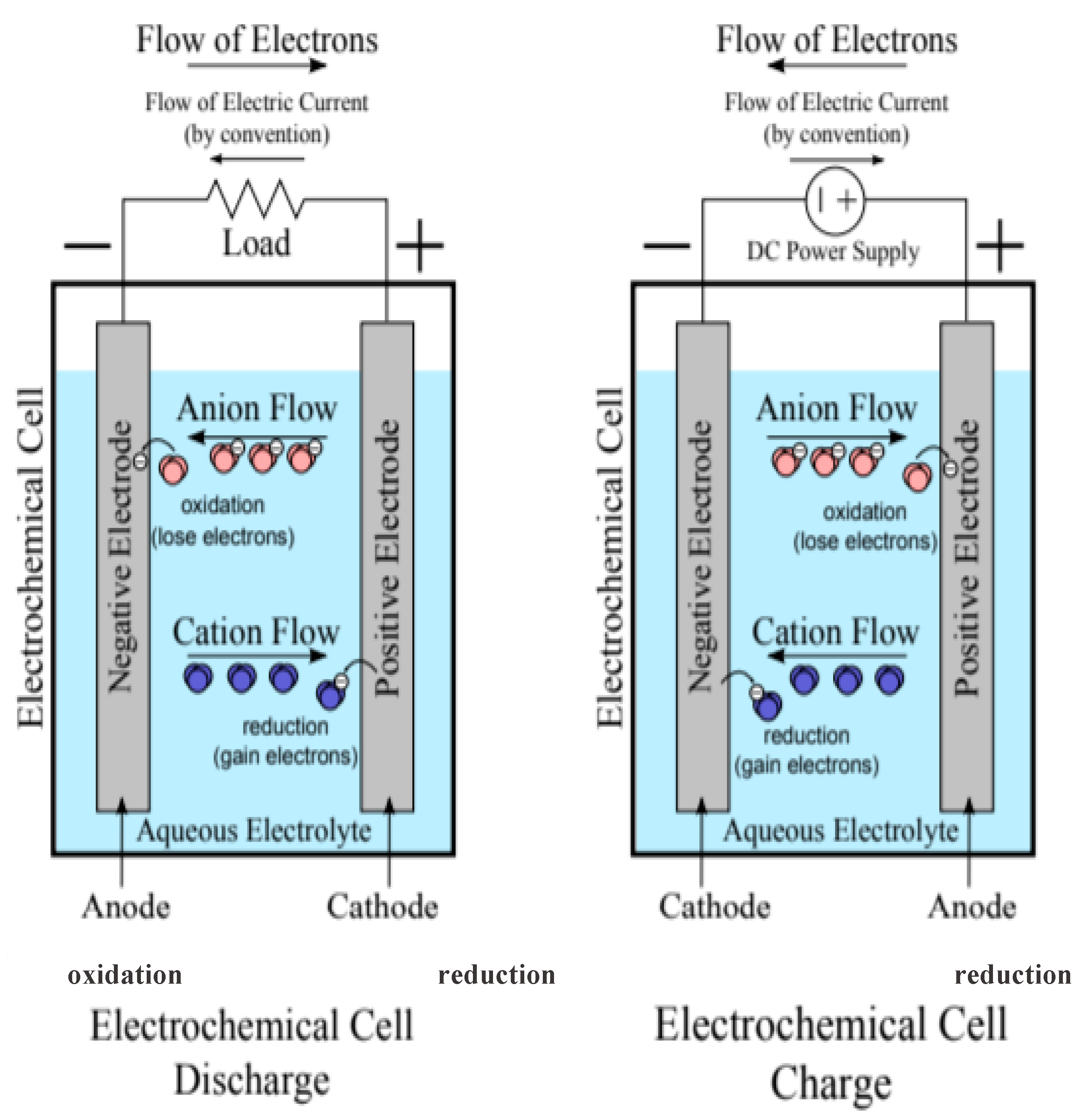
As the oldest technology for electrical energy storage (EES) rechargeable batteries are extensively used in everyday life and industrial applications [54]. An electrochemical battery consists of electrochemically active positive (anode) and negative (cathode) electrodes and liquid or solid electrolytes and stores energy in the form of electric charge and chemical energy in its electrodes’ electroactive materials. During the discharge cycle, electrochemical reactions occur at both cathode and anode simultaneously, a circuit is completed with the flow of electrons through external circuit where electrons originating from anode are collected at the cathode. Whereas during the charging cycle the reverse reaction takes place and the battery is recharged through the application of an external potential at both electrodes, as shown in Figure 7 [55]. Complete chemical reactions (anodic/cathodic) for all widely commercialised battery systems discussed in this review are given in Table 2.
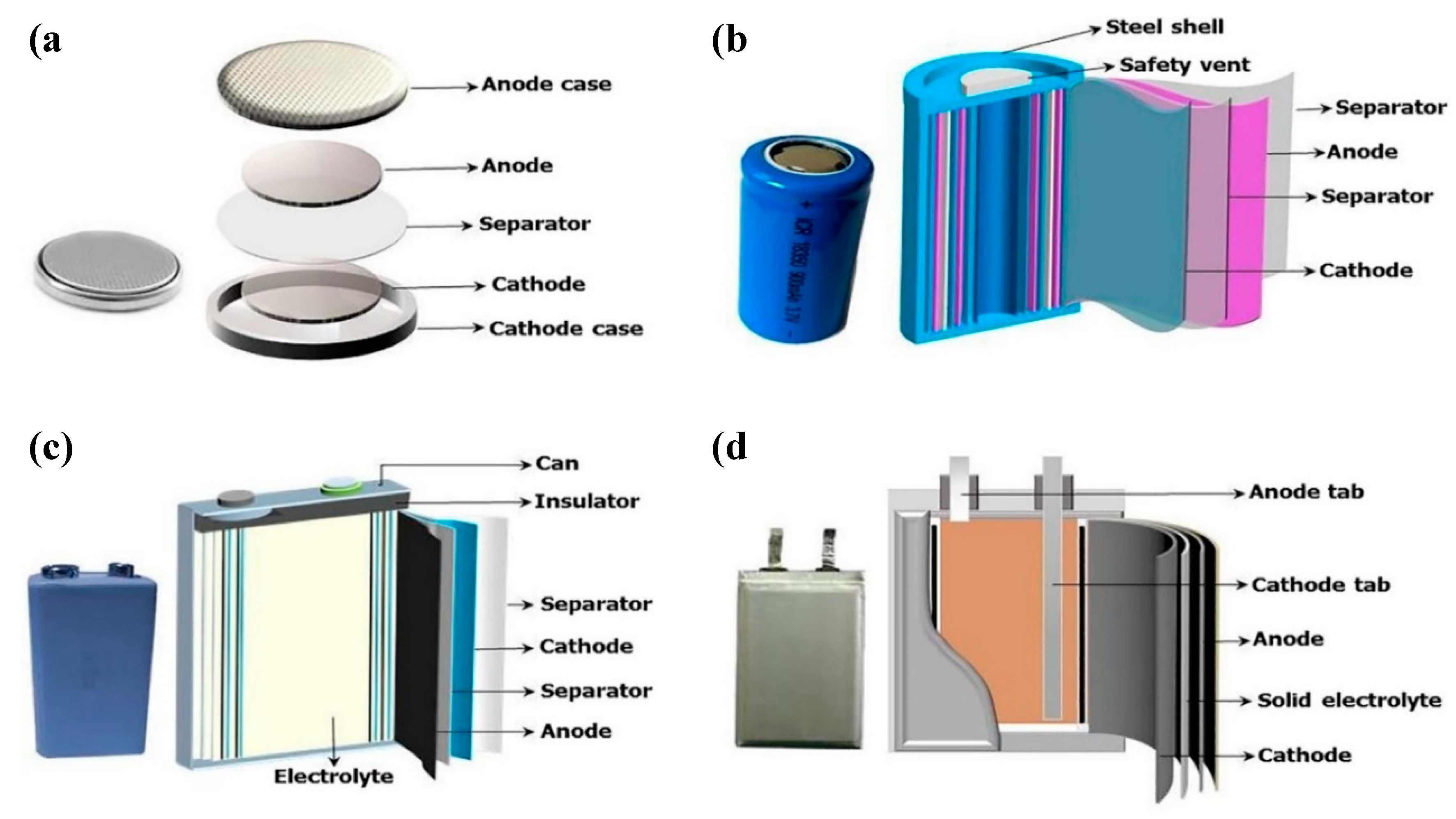
Commercially available rechargeable batteries are usually available in four different shapes i.e., coin, cylindrical, prismatic, and pouch cells as shown in Figure 8.
Electrochemical batteries can be used in a wide range of applications including energy management, transportation, power quality and ride-through power. Installation of battery storage is reasonably straightforward due to flexibility of location and short installation time. Despite these benefits, there are major barriers for their applications in large-scale facilities. These obstructions include relatively low cyclability, comparatively high maintenance cost and inferior power densities. Recycling of spent batteries is another factor which plays a key role for the selection of different battery systems for energy storage applications [58]. In this section of review article, the working principles, advantages, disadvantages and some of the main applications of different rechargeable and flow batteries will be discussed in detail.
Lithium-Ion Batteries (Li-ion)
Lithium ion batteries are currently the most frequently used electrical energy storage technology for a wide range of commercial applications. The main consumption of Li-ion batteries at present is the portable electronic sectors where their excellent properties such as exceptionally low maintenance, excellent cyclability, high voltage (~3.6 V), low self-discharge and very high specific energy led to the displacement of nickel-based battery systems (Ni-Cd and NiMH) which had previously predominated the battery market. Li-ion batteries are also becoming more common in applications such as electric/hybrid electric vehicles (EVs and HEVs), the military and aerospace industries [62,63,64].
Graphite, with its layered structure, is the key anode material for Li-ion batteries however, some acceleration in research activity around non-graphitic carbons, metal oxides and their composites has been witnessed recently [65,66,67]. Lithiated metal oxides such as lithium cobalt oxide, lithium iron sulphates, lithium nickel cobalt aluminium oxide, lithium nickel manganese cobalt oxide and Li manganese oxide are used as cathode materials for Li-ion batteries [68,69]. Conventional Li-ion batteries use liquid electrolytes which consist of lithium-based salts (e.g., LiPF6, LiClO4 and LiAsF6) dissolved in an organic solvent (such as C4H8O3, C3H6O3, C4H6O3 and C5H10O3). Selection of appropriate organic solvents is crucial since they play a fundamental role in improving Li-ion mobility, which ultimately improves overall performance of the battery cell and is also crucial to the safety of the device [70]. New state-of-the-art all solid-state batteries, also known as Li-ion polymer batteries where Li salt containing highly conductive polymer gels replace the conventional liquid Li based salts as electrolyte are becoming commercially available. Li-ion polymer batteries are mainly popular for portable electronics such as mobile phones, ultra-slim laptops and wearable electronics due to their leakage free compact and light cell structure [71,72]. Material composition by percentage weight of different commercially used Li-ion batteries used in various applications including plug-in hybrid electric vehicles (PHEV) where 20 and 40 are all electric range in miles, electric vehicles (EVs) and laptops is provided in Table 3.
Like other electrochemical battery systems, in Li-ion batteries the ions move from anode to cathode by passing through electrolyte and separator while electron flow through external circuit completes the electrochemical reaction. During the discharge cycle, the reaction proceeds in the reverse direction, as shown in Figure 7. A complete electrochemical reaction for Li-ion batteries is given in Table 2, based on the intercalation and de-intercalation of lithium ions.
Performance parameters such as energy/power densities, safety, stability and cyclability of lithium-ion batteries are continually improving as a result of the introduction of new materials (anode, cathode and electrolyte) and improvement in battery technology (stock design, reduced self-discharge and weight). Wang et al. recently produced a cell which showed excellent cyclability with high energy density in which a phosphorus/carbon composite anode was used alongside LiCoO2 (LCO) as the cathode. This cell delivered a highly reversible capacity of 104 mAhg−1 with 100% capacity retention over 2000 cycles [74]. Despite their outstanding characteristics, Li-ion batteries are still lagging behind in some key areas such as their high cost when compared with their counterparts such as lead acid or sodium ion batteries, which originates from the high lithium cost resulting from limited availability and sporadic geographical distribution of elemental lithium reserves. Moreover, at temperatures over 30 ℃ there is a considerable drop in capacity retention and cyclability over longer period of time in Li-ion batteries. Another major issue which surrounds Li-ion batteries is their operational safety, since additional protection circuits are required to limit circuit currents and voltages for their safe operation to avoid overloading [57]. Currently research is under way to address these issues and improve battery technology even further in order to enhance the suitability of Li-ion batteries for a wider range of applications.
Lead-Acid Batteries (Pb-A)
The lead-acid (Pb-A) battery was invented by French physicist Gaston Planté in 1859. In a standard Pb-A battery cell PbO2 is used as the cathode and Pb as the anode with sulphuric acid used as an electrolyte. The chemistry of this type of battery system is considered mature, robust and well understood, with Pb-A batteries considered one of the most technologically developed and commercially successful battery systems [75,76]. The complete composition of the various constituents of these batteries by percentage weight is given in Table 4. Lead-acid batteries retain the largest market share both in terms of production capacity (MWh) and sales volume, the automotive industry being the principal user with secondary markets for other industries such as standby and emergency power sources, portable electronic devices and telecommunications/data networks applications, making it the market leader [77]. Lead acid battery systems are based on particularly complex primary and secondary electrochemical reactions. Cathode and anode are comprised of lead peroxide (PbO2) and sponge lead (Pb) on lead lattice respectively using water and sulphuric acid solutions as electrolyte. During complete reversible charge/discharge reactions lead and lead peroxide are converted into lead sulphate (PbSO4) [78], complete electrochemical reaction is given in Table 2.
Lead-acid batteries can be further divided into two groups: valve regulated and sealed lead-acid batteries. Valve regulated batteries have valves installed in order to release excess pressure generated at positive electrode during oxygen reduction reaction whereas sealed lead-acid batteries with innovative and improved technology, known as valve regulated lead acid (VRLA) based battery cells, were introduced between 196 and 1975 and are completely sealed [81,82]. VRLA based battery systems are more compact in size than valve regulated cells making them more useful for small scale applications such as small portable devices. In contrast, valve operated battery systems can be readily scaled up, resulting in higher storage capacity leading to a broader application base such as in emergency lighting, uninterruptible power supplies (UPS) and as energy sources for power telecommunication. Although, VRLA technology did not improve the operating performance (energy/power densities) of Pb-A based battery systems they resulted in additional benefits due to lower electrolyte content, including a lower level of maintenance, improved reliability and most importantly it is easier for them to meet airfreight and transportation regulations. Other benefits of Pb-A batteries include fast response times, small daily self-discharge rates (<0.3%), relatively high cycle efficiencies (~63–90%) and low capital costs (50–600 $/kWh) [83,84,85]. Other advantageous properties of lead-acid batteries which make them a commercially attractive technology include cost-effectiveness, excellent rate capability, outstanding charge retention and good performance over wide temperature ranges.
Despite these beneficial properties, lead-acid batteries suffer from short life span (300–500 cycles), pose environmental concerns, possess a relatively poor energy density (40 Wh kg−1) and suffer acid stratification [77,86]. Moreover, VRLA based Pb-A batteries suffer from ‘dry out’ failures and perform poorly at low temperatures, requiring temperature controlled voltage management systems to address these issues which increases the overall cost of a battery system [87,88]. In order to address the performance and operational issues of lead acid batteries, currently R&D in Pb-A batteries focuses on: (a) material innovation for battery performance enhancement such as cyclability and deep discharge capability improvements; (b) reduction in response time; (c) optimization of battery technology for their commercialisation in a wide range of applications including transportation sector and photovoltaic power integration [89].
Nickel-Cadmium Batteries (Ni-Cd)
The nickel-cadmium battery system was first patented by Swedish engineer Waldemar Jungner in 1899 [90]. Metallic cadmium and nickel hydroxide are used as anode and cathode respectively along with an aqueous alkali solution such as potassium hydroxide (KOH) as an electrolyte which does not undergo significant changes during operation. Anode and cathode are separated by a three-layer porous polymeric separator which normally consists of nylon/polypropylene/nylon layers assisting in electrolyte diffusion [91]. The material composition of a typical nickel-cadmium battery is given in Table 5, where it can be seen that the fundamental material composition can vary substantially depending on application. In a Ni-Cd Cell Ni is reduced (NiOOH → Ni(OH)2) at the cathode during the discharge cycle and cadmium (Cd) is oxidized (Cd → Cd(OH)2) at the anode. During charging the reverse reactions take place. However, during the discharge cycle oxygen and hydrogen are produced at the positive and negative electrodes, respectively requiring the addition of water and venting [92]. The complete chemical reaction scheme for the operation of a Ni-Cd battery system is given in Table 2. The composition of the various constituents of Ni-Cd batteries by percentage weight used for automotive and portable electronic applications is given in Table 5.
Nickel-cadmium batteries operate on the same working principle as other electrochemical battery systems but with two distinctive designs, one a completely sealed cell and other with a vent to release gases (oxygen and hydrogen) [94,95]. Sealed cells are used in everyday life whereas vented Ni-Cd batteries are used in aircraft and diesel engine starters, where large energy per weight and volume are critical [96]. The nickel-cadmium battery system offers advantageous properties including fast charge/discharge and long cycle life (they can complete up to 3000 cycles). They can tolerate deep discharge rates without any capacity loss and have good size flexibility (ranging from small portable devices to large vented cells) in comparison to other battery systems such as the lead acid batteries. As a result of these remarkable characteristics, Ni-Cd batteries were widely used and had the largest market share until the 1990s in applications such as standby power sources and portable applications, before losing market share to other, superior, rechargeable battery systems such as lithium-ion batteries [97,98,99]. The disadvantageous characteristics of the Ni-Cd system, such as environmental concerns due to cadmium toxicity and their high production cost (nearly ten time higher than lead-acid batteries) limit their wider use. Another drawback of Ni-Cd batteries is that they suffer from ‘memory’ issues which limit their capacity if they are un-used for extensive periods or not discharge completely before charging [100,101].
Nickel-Metal Hybrid Batteries (Ni-MH)
Nickel metal hydride (Ni-MH) battery technology is a further development of nickel-cadmium batteries with the key objective of addressing two fundamental issues-high cadmium cost and environmental concerns. Ni-MH batteries can be considered an improved form of Ni-Cd batteries since both have similar configurations, with identical cathode and electrolyte material. The primary difference is that the anode in Ni-MH is replaced with an hydrogen absorbing alloy [102]. Additionally, cell voltages and charge/discharge curves are also identical for both battery systems. As shown Table 2, similar to lithium-ion batteries in which Li ions transfer between the electrodes during the operation of the battery, in the overall cell reaction of a Ni-MH batteries, hydrogen is transferred from one electrode to the other [103]. The very simple electrochemical reactions of Ni-MH batteries provide the basis for their long cycle life (~500 cycles) and fast kinetics (high power densities, typically ≥ 1000 Wkg−1)2. The typical material composition of leading Ni-MH batteries is outlined in Table 6.
NiMH batteries are inferior to Li-ion cells however, some of their key characteristics that make them preferable choice over Ni-Cd technology, particularly for applications in portable electronic devices include: an insignificant memory effect, outstanding performance over a wider temperature range, rapid charging (they can be fully charged within an hour) and a high energy density (50% higher than the energy density of Ni-Cd batteries) [105,106]. Electric/hybrid electric vehicles (EVs/HEVs) such as the Toyota Prius are significant users of Ni-MH batteries. Applications of Ni-MH batteries depend on the nickel-metal hydride cell’s chemistry, where the cell offers tolerance to both overcharge and over-discharge through gas recombination reactions. This results in a maintenance free battery cell since there is no pressure build up even inside a totally sealed battery cell. This extraordinary capability of the Ni-MH cell eliminates the requirement for cell voltage monitoring, which results in simplified battery management systems (BMS) as compared with other high energy density systems such as sodium-sulphur and lithium-ion systems [107,108].
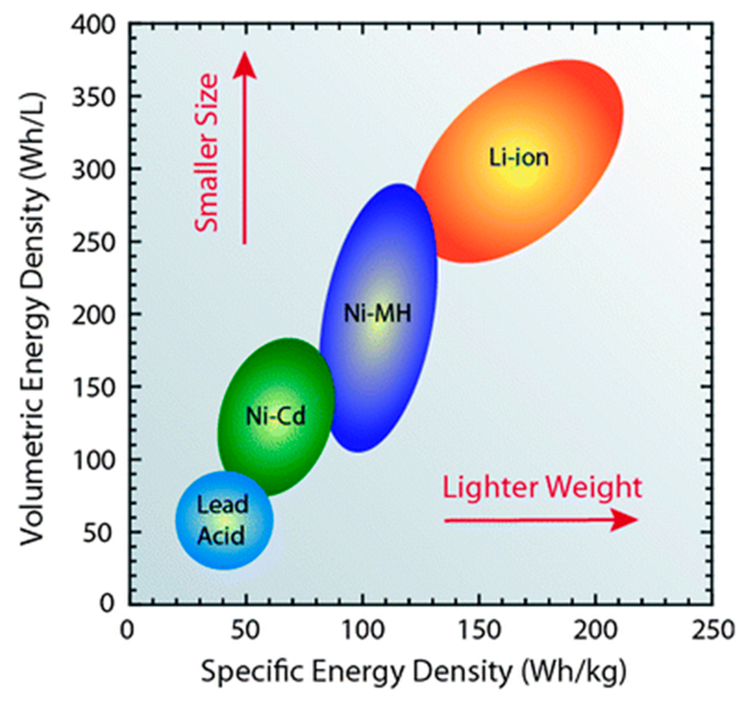
The applications of Ni-MH batteries are declining with time due to collective effects of the development of other efficient battery technologies (such as lithium-ion batteries) and the deficiencies of Ni-MH battery systems. The principal drawback of Ni-MH cells is their very high self-discharge rate (up to three times that of Ni-Cd batteries and even higher when compared with other rechargeable battery systems such as lead-acid or lithium-ion) which results in a Ni-MH battery losing up to third of its charge within a month even without being used. The self-discharge issue of the battery is less noticeable in applications such as EVs/HEVs due their frequency of use, but it becomes more prominent in occasionally used portable electronic devices. Other disadvantages include a high material cost which makes them less competitive to other rechargeable batteries such as lithium-ion in longer term [109,110]. The key objective of all rechargeable battery systems is to increase their energy densities without compromising on their power densities, while simultaneously restricting their mass and volume to allow the diversification of their applications. Figure 9 illustrates the relationship between energy and power densities of various commercialised rechargeable battery systems among them the Li-ion battery shows the highest gravimetric and volumetric energy densities. These are the main characteristics which make Li-ion batteries commercially successful electrical energy storage technology.
As discussed above, an ideal battery system needs to possess high energy/power densities coupled with fast charge/discharge rates, operational safety, and appropriate cyclability. The advantages and disadvantages of the four rechargeable battery systems discussed above are summarized in Table 7, which gives a comprehensive understanding of the different characteristics of these rechargeable battery systems.
3.1.2. Flow Batteries
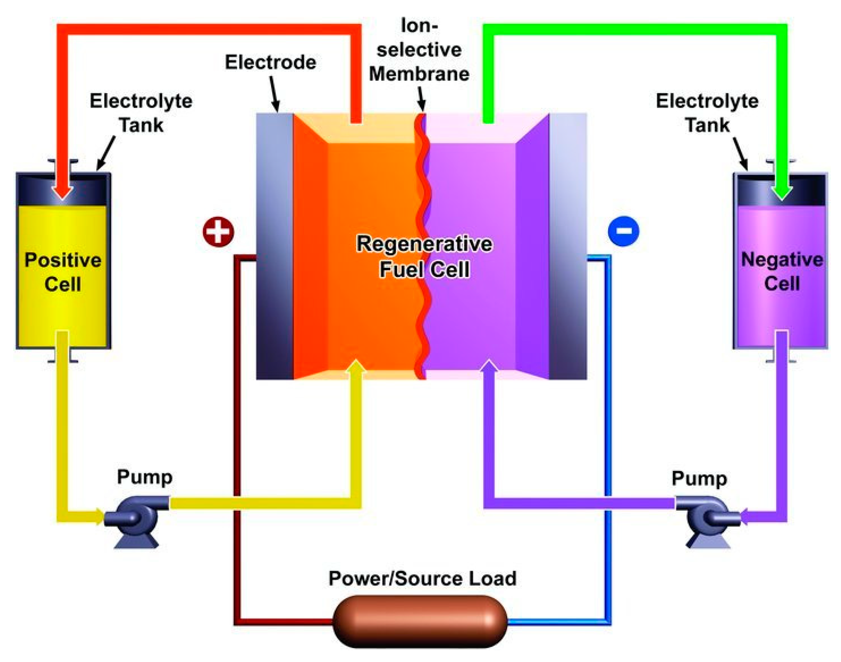
A flow battery system is comprised of two external liquid electrolyte tanks connected to a cell stack and separated by an ion selective membrane, as shown in Figure 10. Electrolytes are pumped from electrolyte tanks to the cell stack where operation is based on reduction-oxidation reactions of the electrolyte solutions. Electrical energy is converted into chemical energy during charging, when one electrolyte is reduced at the cathode and the other electrolyte is oxidized at the anode. During the discharge phase the same process is completed in reverse direction [113].
Flow batteries can be classified into two groups: hybrid flow batteries and redox flow batteries. Properties such as design flexibility and scalability, low toxicity, safety, durability and un-limited capacity make flow batteries a favourable option compared with currently available electrochemical energy storage technologies for energy storage in large scale applications [115,116,117]. The shortcomings of flow batteries include a comparatively high manufacturing cost, inferior performance resulting from non-uniform pressure drops and reactant mass transfer limitations and highly complicated system requirements when compared with other rechargeable batteries [118,119]. Some of the most technologically mature flow battery systems include vanadium redox flow battery (VRB), zinc bromine (ZnBr) flow battery and polysulfide bromine (PSB) flow battery. These battery systems are still at research stages and have not seen widespread applicability and commercialization when compared with commercialized rechargeable batteries. Some of their fundamental technical characteristics including energy/power densities, cycle-ability, self-discharge, cyclic efficiency and battery lifetime are compared in Table 8.
3.2. Fuel Cells
The development of fuel cell technology can be traced back over 180 years to Sir William Grove’s pioneering work experimentally demonstrating the electrolyser /fuel cell in 1839 [120]. This was followed by construction of a full-scale device (initially called a gas battery which latter came to be known as fuel cell) in which electricity was produced by combining oxygen and hydrogen in a cell. The British engineer Francis Thomas Bacon has been credited with developing the first fully operational fuel cell in 1959, which was later adopted by NASA for space research [121]. NASA used both alkaline fuel cells (AFC) and polymer electrolyte membrane fuel cells (PEMFC) for space exploration missions such as Gemini and Apollo in the 1960s. In the 1990s PEMFC and direct methanol fuel cells (DMFC) attracted worldwide interest, which resulted in further development in this field. Currently fuel cell technology is witnessing huge research drive, resulting in improvement in technology which will lead to widespread commercialisation. The fuel cell is an electrochemical energy conversion device where chemical energy is directly converted into electrical energy, resulting in high energy conversion efficiencies. This exchange of energy takes place within the core of the cell which comprises of an electrolyte in direct contact with the cathode (positive electrode) and anode (negative electrode). According to their fuels, operating temperatures and electrolytes, fuel cells can be classified into six main categories as follow [122,123].
- Solid oxide fuel cell (SOFC)
- Proton exchange membrane or polymer electrolyte membrane fuel cell (PEMFC). These can be further subdivided into standard PEMFC (operating below 100 ℃) or high temperature PEMFC or HT-PEMFC (operating in temperature ranges of up to 200 ℃).
- Molten carbonate fuel cell (MCFC)
- Alkaline fuel cell (AFC)
- Phosphoric acid fuel cell (PAFC)
- Direct methanol fuel cell (DMFC)
- Single layered fuel cell (SLFC)
Fuel cell technology has seen a limited use in nearly all types of power applications, ranging from the small scale such as personal computers and cell phones (up to 10 kW) to medium range applications such as transport applications (up to 100 kW) and lastly in large scale power applications (up to 10 MW) [124,125,126]. The operational and technical aspects and recent developments of some of the key fuel cells are discussed briefly in the following subsections.
3.2.1. Solid Oxide Fuel Cell (SOFC)
Solid oxide fuel cells (SOFCs) differ significantly from their counterparts since they are solid state devices without any moving components and have distinguishing characteristics such as combustion free operation, low emissions, inherently high conversion efficiencies and very high operational temperatures (in the range of 800–1000 °C). Efforts have been made to introduce new electrode materials to improve their thermal stability, electrical conductivity, catalytic activity, chemical compatibility and cost-effectiveness especially with the drop in operational temperature from to 400–700 °C.

| Fuel Cell Type | Operating Temperature (℃) | Output (kW) | Efficiency (%) | Applications | Advantages | Disadvantages |
|---|---|---|---|---|---|---|
| Alkaline | 900–100 | 10–100 | 60 | (i) Military/Space | (i) Faster cathode reaction in alkaline electrolyte (ii) Variety of catalysts used | (i) Costly removal of CO2 |
| Molten Carbonate | 600–700 | 1–1000 | ≥40 | (i) Electric utility (ii) Distributed generation (large scale) | (i) High efficiency (ii) Fuel flexibility (iii) Variety of catalysts used | (i) Complex electrolyte management (ii) High operating temperature (iii) Slow start up |
| Polymer electrolyte membrane | 50–100 | 1–250 | 53–58 | (i) Backup power (ii) Portable power (iii) Transportation (iv) Distributed generation (small scale) | (i) Solid electrolyte: reduced electrolyte and corrosion issues (ii) Quick start up (iii) Low temperature | (i) Expensive catalyst requirement (ii) Highly sensitive to fuel impurities (iii) Low temperature (Heat wastage) |
| Direct methanol | 60–200 | 0.001–100 | 40 | (i) Portable devices | (i) Reduced cost due to the absence of fuel reformer | (i) Methanol high toxic and flammable (ii) Low efficiency |
| Phosphoric acid | 150–200 | 50–1000 | 40 | (i) Distributed generation | (i) Higher overall efficiencies (ii) Increased impurity tolerance | (i) Platinum catalysts required (ii) Low power output (iii) Large size |
| Solid Oxide | 600–1000 | 1–3000 | 35–45 | (i) Electric utility (ii) Auxiliary power (iii) Distributed generation (large scale) | (i) High efficiency (ii) Fuel flexibility (iii) Suitable for CHP (iv) Hybrid GT/Cycle (v) Variety of catalysts used | (i) High temperature enhances cell breakdown and corrosion (ii) Slow start up |
| Single layered | 550–750 | 97–98 | (i) Transportations (ii) Portable devices | (i) High efficiency (ii) Low cost (iii) Low emissions | (i) Un-tested technology |
Selection of suitable anode materials is a key to maintain superior performance of SOFCs, since anode materials accounts for nearly 95% of the overall percentage of material in anode supported cell. Most commonly used anode material in SOFCs is Ni-YSZ due to its high stability and excellent conductivity however, the materials is susceptible to carbon deposition when comes in contact with hydrocarbon fuels [130]. Song et al. improved the performance of a Ni-YSZ based SOFCs through doping of its anode by adding Al2O3 to Ni-YSZ which resulted in improved electrical conductivity, decreased anode activation polarisation and nearly 39% improvement in performance of the cell [131]. Other anode materials used in SOFCs include CrTi2O5, Cu-CeO2, CrTi2O5 La0.8Sr0.2Fe0.8Cr0.2O3 and Sc0.1Y0.1Zr0.6Ti0.2O1.9 [132].
The cathode is another fundamental component of a SOFC system and has different selection criteria when compared to the anode since the cathode in a SOFC requires distinctive operational properties such as high level of porosity and stability in oxygen environment. Also due to their elevated operating temperatures, SOFCs use more cost-effective and widely available transition metal oxides such as Cu, Co, Ce, Sr and Ni as an alternative to costlier metals such as Pt as cathode since high temperature operations of the cell result in sufficiently improved kinetics and thermodynamics of the chemical reactions underpinning fuel cell operation. Moreover, SOFCs can be used as a substitute for electrochemical batteries due to their high efficiencies even in in reverse mode as solid oxide electrolysis cells (SOEC) in which steam is electrolysed into hydrogen by feeding water and electric current into the cell to produce hydrogen and oxygen. [133]. Owing to these excellent properties and their modularity, fuel adaptability, diverse scale of application (small, medium and large scale) and vibration free, quiet operation, SOFC are promising candidates for use in the field of energy storage and conversion in the future [134,135].
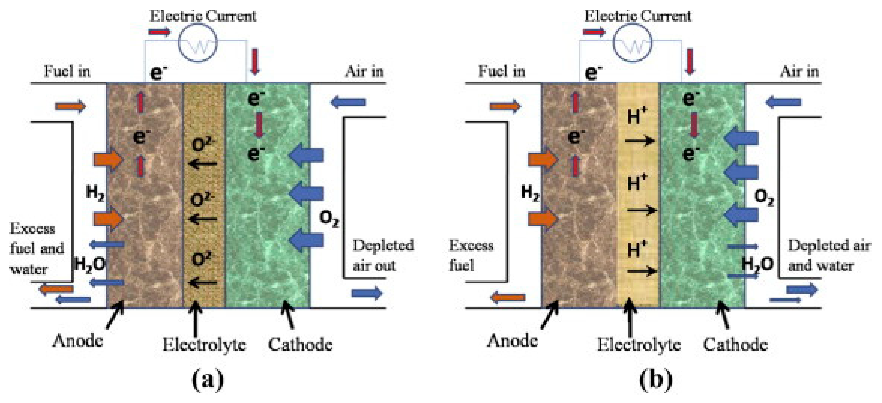
The basic structure of a SOFC consists of a porous anode and cathode sandwiched around a ceramic based solid electrolyte such as yttria-stabilised zirconia (YSZ) or gadolium-doped ceria (GDC), as shown in Figure 11.
Electrons are generated at the anode through oxidation and are accepted at the cathode for oxygen reduction, resulting in circuit completion with the production of electricity due to the flow of electrons from anode to cathode through an external circuit. The chemical reactions at the anode and cathode are given by Equations (9)–(13) below. A detailed discussion of the chemical reactions and mechanism of energy conversion in a SOFC is given by Tesfai et al. [137].
Anode:
Cathode:
SOFC technology has the potential to transform the overall electrical energy generation landscape with insignificant environmental impact if it is more extensively commercialised. Their commercialisation has nonetheless been limited by several disadvantages such as high material costs, the requirement of high operating temperatures (800–1000 °C), safety issues and the complex stack and cell assembly. Furthermore, high operating temperatures have added issues including catalyst poisoning, electrode sintering, electrode/electrolyte interfacial diffusion and thermal/mechanical stability. These issues, and particularly the need for high operating temperatures, has forced research towards low temperature SOFC technology. The benefits of lowering operating temperatures include widening the area of application and improving the life span of the SOFCs, technical improvements (i.e., reducing the likelihood of cermet anode’s redox degradation) and economic advantages (i.e., using more cost effective cell components) [138]. Asia and co-workers reported improved electrochemical performance of SOFCs where co-doped Sr/Sm–ceria–carbonate electrolyte was employed within the temperature range of 400–580 °C with H2 as fuel, as opposed to the more commonly studied samarium doped ceria. This nanocomposite electrolyte was found to display excellent power density, reaching ~900 mW cm−2 [139].
The development of different components and stock designs has enabled SOFC technology to become increasingly cost-effective, efficient and has resulted a drop in operating temperatures. These improvements have made SOFC devices more desirable for wide ranging industrial applications however, there are numerous challenges remaining to be addressed through further research including high oxygen ion resistance through solid electrolyte, over potential, non-compatibility in oxidising and reducing environments.
3.2.2. Direct Methanol Fuel Cell (DMFC)
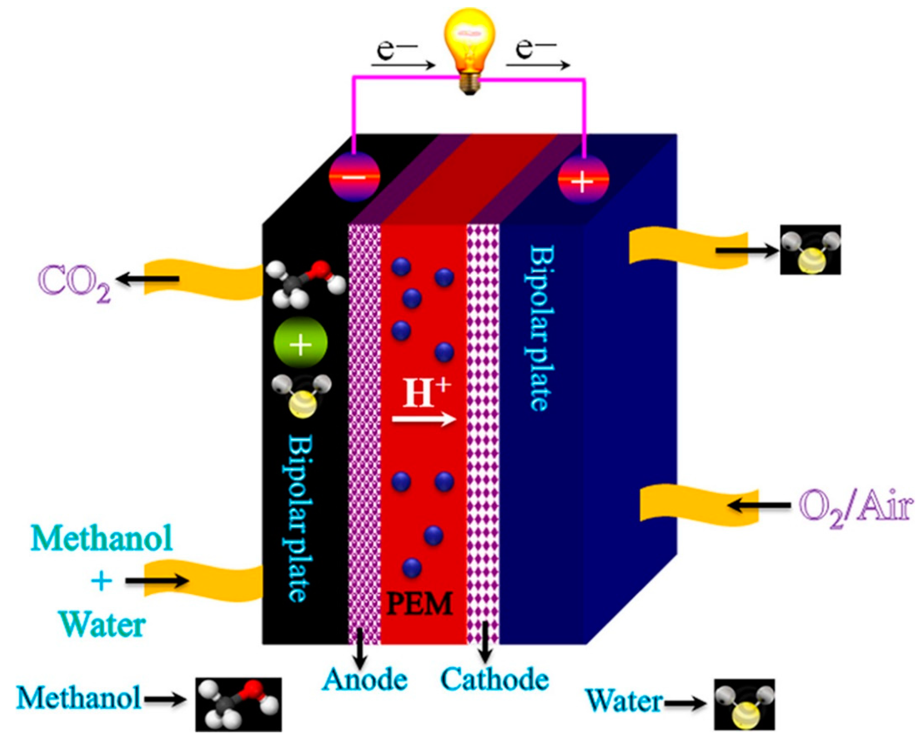
Direct methanol fuel cells are considered as a subcategory of proton exchange membrane (PEM) fuel cells and can also be considered as low operating temperature PEM, where methanol is used as fuel. DMFCs work on the principle of directly converting the chemical energy of high energy density liquid methanol fuel to electric power via electrochemical processes with carbon dioxide and water as by products [140,141]. The potential for adoption of DMFCs as a key energy conversion device is predominately a result of the high specific energy of pure methanol (up to 6000 Wh kg−1) [142]. A schematic representation of a DMFC system is shown in Figure 12, illustrating its basic working principles (e.g., reactants/products gasses and ion conduction flow direction).
The electrochemical reaction between oxygen and methanol occurs at cathode and anode respectively whereas the complete electrochemical reaction of DMFC is given by Equations (14)–(16) below:
Anode:
Cathode
Complete reaction:
Methanol is a fuel with an excellent conversion efficiency, reaching around 96.5% which is much higher than internal combustion engine, the latter being restricted by Carnot cycle [144]. The efficiency of methanol conversion is explained through the electrochemical process described above. The maximum achievable theoretical operating voltage in a methanol-air cell is ~1.21 V, although this cannot be attained in practical operation due to sluggish reaction kinetics and ohmic losses in the electrolyte [145,146].
One of the benefits of using methanol as fuel in DMFC is the storage and transportation of methanol, which is much easier than fuels such as hydrogen. Moreover, there is the added benefit of the high energy density of methanol, which is three orders of magnitude higher than hydrogen. Direct methanol fuel cell technology is considered promising due to characteristics such as high-power density, low operating temperatures and easy start up. However, DMFC suffers various drawbacks which hinder its wider commercial use. Firstly, the overall performance of DMFC degrades with time due to the methanol crossover the through electrolyte membrane [142]. Effort have been made to address this issue by designing composite membranes. Yan and co-workers produced composite membrane by sandwiching a monolayer graphene between two thin Nafion membranes which resulted in drop in methanol permeability by nearly 69% [147]. Secondly, large amount of gaseous CO2 is released during methanol oxidation which disturbs the methanol transport to catalyst sites and contributes towards polluting the Environment [148]. Thirdly, voltage losses on the cathode side increase due to impeded oxygen transportation to the catalyst sites resulting from high water flux through the membrane [149]. Finally, the kinetics of the methanol electrochemical reaction are much slower than that of hydrogen, which is a major component of the overall voltage loss at anode whereas in the hydrogen cell the anode voltage loss is negligible [121].
3.2.3. Polymer Electrolyte Membrane Fuel Cell (PEMFC)
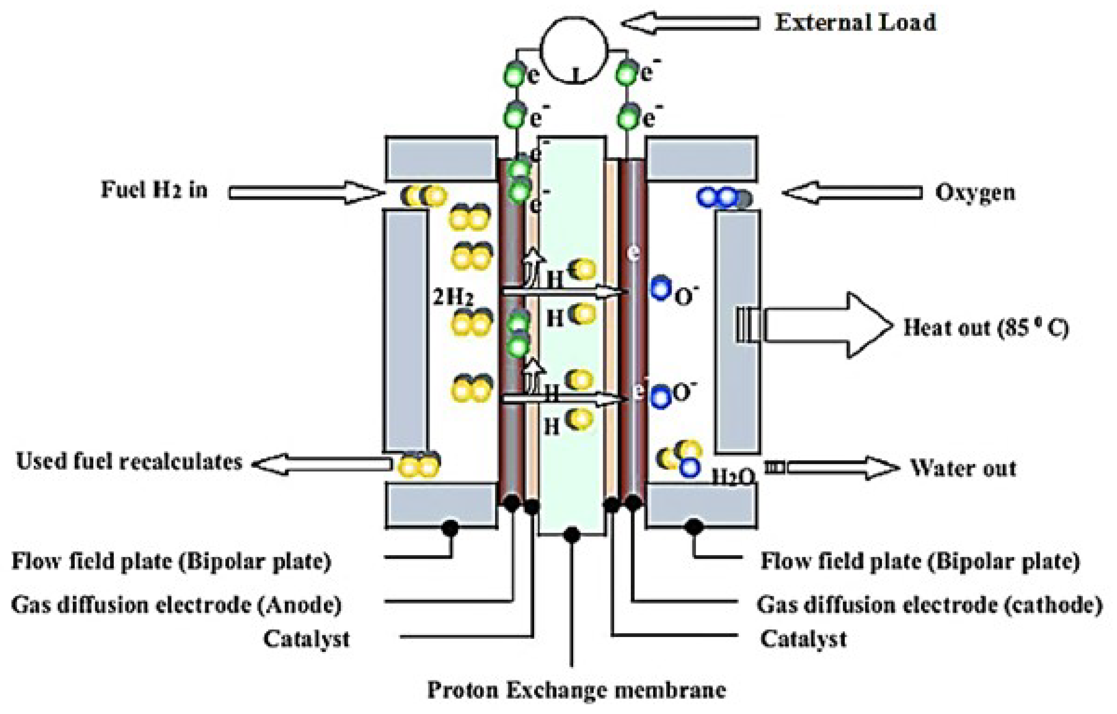
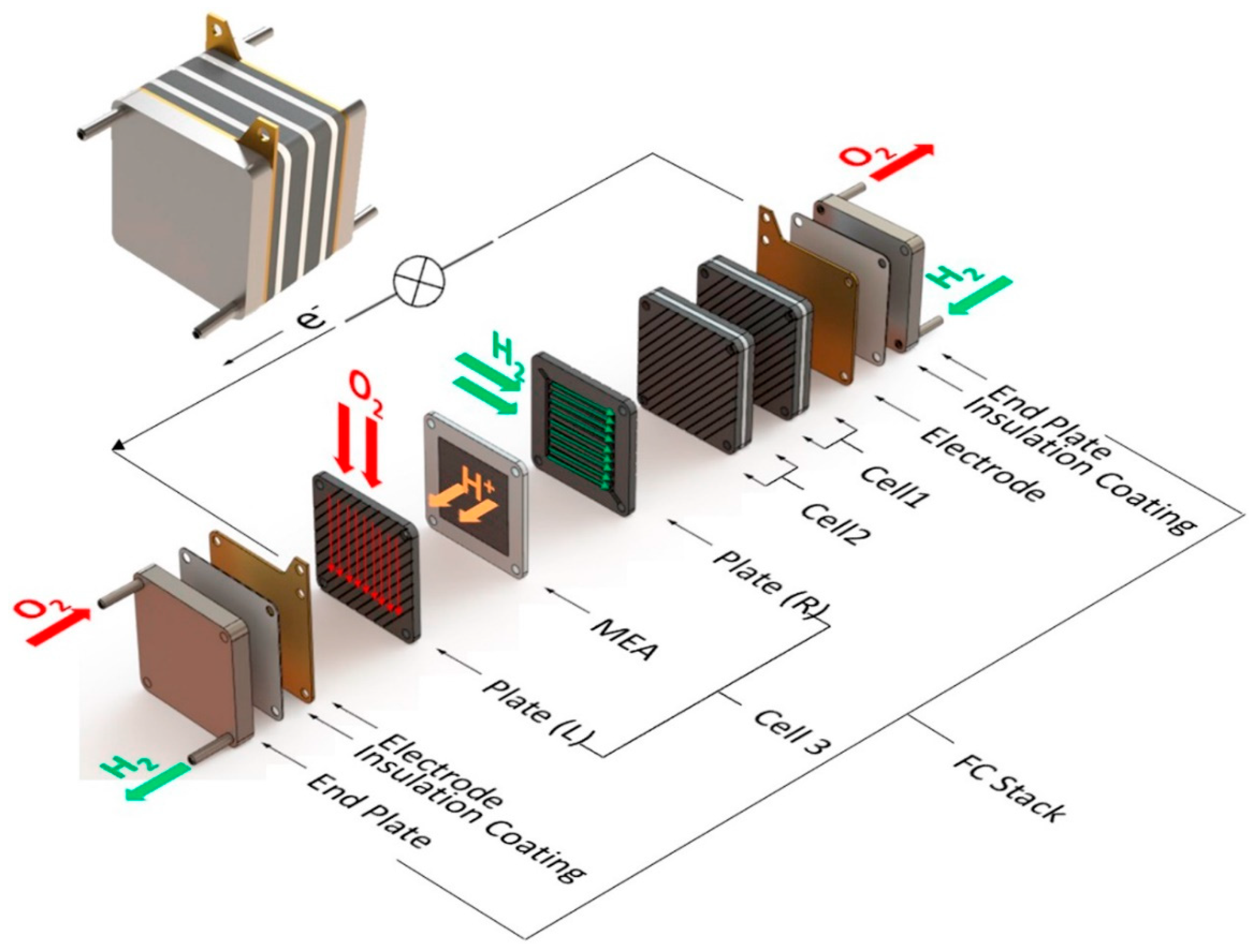
The working principle of polymer electrolyte membrane fuel cell (PEMFC) is similar to that of other fuel cells. Its structure consists of a gas diffusion layer (GDL), polymer electrolyte membrane (PEM), bipolar plate and catalyst layer (CL), as shown in Figure 13. Electrochemical reactions occur in the CLs while reactant gases flow through the GDL with hydrogen supplied to the anode and air or oxygen to the cathode. The chemistry of these cells leads to water being the only by-product, making the operation of PEMFCs completely environmentally friendly.
Advantageous properties such as low noise, lower operating temperature, high power density and excellent dynamic properties make PEMFCs a promising power source for automotive applications. In addition, the simultaneous generation of both heat and power with high efficiency makes the PEMFC highly suitable for residential power generation applications. In this case, additional heat generated during fuel cell operation can be used by households, which ultimately increases the overall efficiency of the cell especially high temperature HT-PEMFCs. HT-PEMFCs operate at temperature range of 100–200 °C which is considerably higher than 60–80 °C for low temperature LT-PEMFCs which provides wider range of thermal energy usage [151]. However, the cost of PEMFCs is still considered a major obstacle for frequent use in this area of application [152]. PEMFCs are also a promising power source for portable electronic such as cell phones, laptops and military radio/communication devices, due to their high energy capabilities and small stack size [153,154,155]. Although cost once more hinders major applications, there is potential for some usage scenarios such as a backup power source in telecommunication companies and banks, where the cost associated with breakdown is sufficiently high to offset the investment required to deploy this technology.
To attain sufficiently higher power outputs to meet the requirements of specific applications, fuel cells can be stacked up as shown in Figure 14, where currents and voltages ranges between 0.5–1 A cm−2 and 0.4–0.9 V respectively [156,157].
World-wide commercialisation is under achieved for PEM fuel cell technology where cost and durability are two major barriers. Furthermore, various components of the fuel cell, particularly the membrane electrode assembly (MEA), suffer degradation during long term operation [159]. In general, the typical expected lifetime of a PEMFC is around 2500 hrs, which is well below the required life expectancy of 5000 hrs and 40,000 hrs for transportation and stationary applications, respectively [155,160]. Cost is another major impediment towards commercialisation of this fuel cell technology, with the catalyst (which is Pt based) and MEA (Nafion membrane) being two key contributors towards higher costs. However, Pt loading has been reduced by two orders of magnitude with the potential for further reduction, and there has been a drop in the cost of the MEA, bringing the fuel cell cost down towards the target of $30 kW−1 for PEMFCs [161]. Mass production (which will improve the cost effectiveness) and further improvements to materials (to enhance the durability) are nonetheless necessary to overcome fundamental barriers of cost and durability while maintaining the performance for wider deployments of PEMFC technology.
3.2.4. Single Layer Fuel Cell (SLFC)
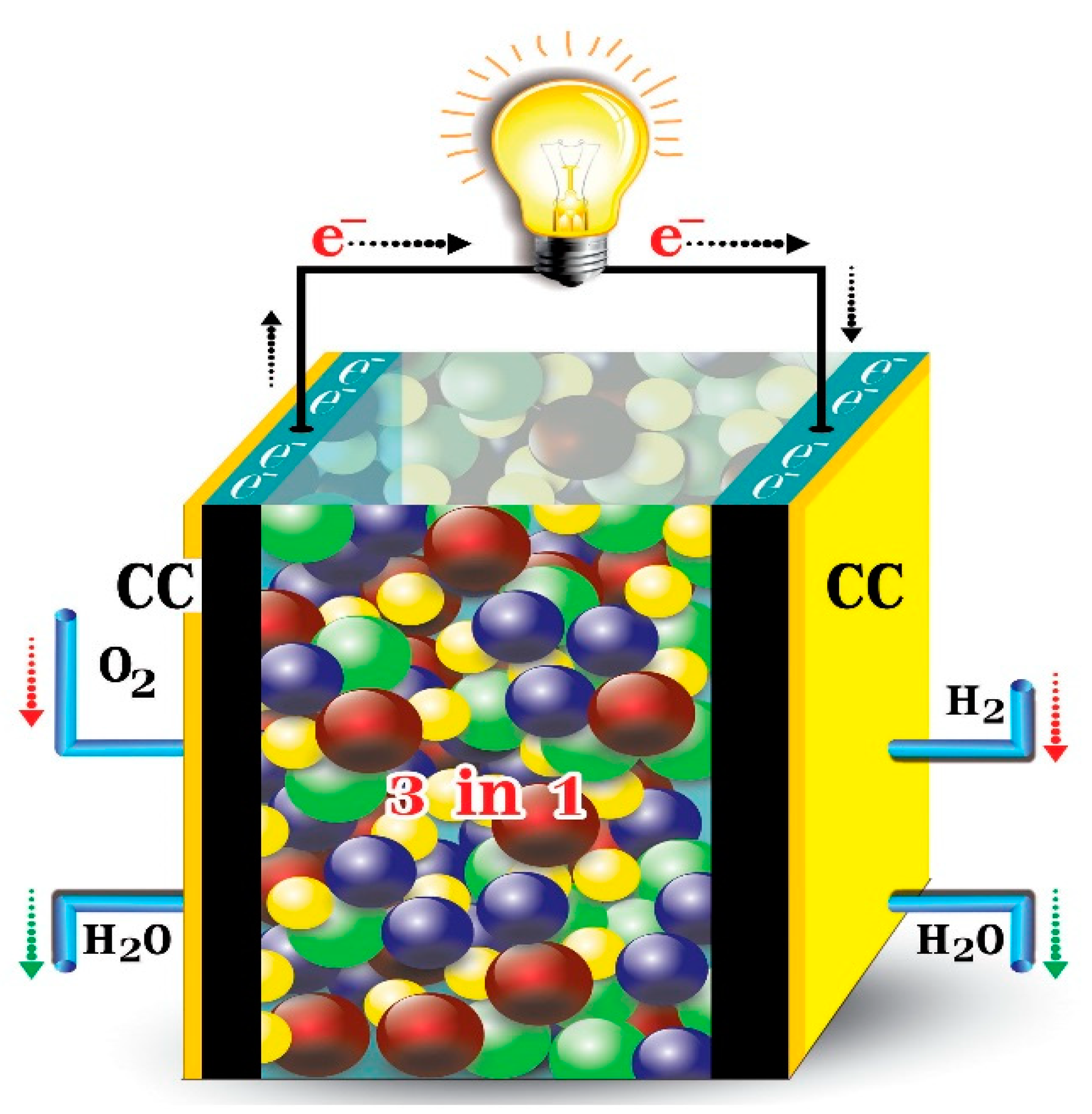
A new type of fuel cell, the single layer fuel cell (SLFC), has been reported recently based on semiconductor and an ionic conductor material. In contrast to a conventional fuel cell, the single layer fuel cell merges all three functional layers into one and is therefore also known as an electrolyte free fuel cell. Material composition and microstructure can be adjusted within the cell in order to reach a balanced ion/electron-conductivities and to reduce the lattice mismatch inside the fuel cell, hence enhancing the efficiency and performance. In a single layer fuel cell, the mixture of ionic and semiconducting materials provides the electrochemical reaction sites and charge transport medium respectively. The functional layer of a conventional fuel cell is the electrolyte layer whereas in a SLFC the nanocomposite material inside the single layer acts as a complete fuel cell [162]. This newly developed fuel cell was reported by Zhu and co-workers as “three in one”, which is significantly different from the conventional anode/electrolyte/cathode three-layer structured cells [163]. Where cell technology is less complex and has reduced material requirements. The material choice of SLFC widely involves semiconductors, electronic/ionic conducting materials including not only existing SOFC electrolyte and electrode, but also more semiconductors and hetero-structured composites than a traditional SOFCs.
The SLFC structure is presented schematically in Figure 15. Mixed ionic and semiconductor materials are used to assemble the cell, both sides of this composite single layer is pasted by current collector (CC) for the current collection during the electrochemical operation. During this process, the side of SLFC which comes in contact with the hydrogen fuel becomes the anode while the side coming in contact with oxygen becomes the cathode. The anode side releases electrons by creating H+ ions while the cathode side receives electrons, hence generating electricity and water.
Compared with a conventional three-layered fuel cell, SLFC boasts a simplified cell structure and assembly consisting of a single functional layer, which should result in reduce production costs and making this type of fuel cell suitable for commercial applications. The full reaction scheme for the SLFC can be described into two steps, given by Equations (17)–(19) [164].
Reaction at hydrogen-contacting (fuel) side:
Reaction at the air contacting side:
Complete electrochemical reaction:
New technologies always come with associated challenges and in the case of the SLFC, researchers are working to derive a sufficiently detailed explanation of its behaviour, however it has not yet been possible to fully explain its operating mechanism for its functionality. Its overall behaviour is similar to that of conventional fuel cell with all the functionality of the three layers of the latter occurring in a single layer. This type of fuel cell has similar applicability as any other conventional cells but should be more suitable for transportation and PEDs. This new device is expected to be low cost, efficient and have very low emissions compared with similar conventional device.
Table 8 summarises the operational parameters, applications, advantages, and shortcomings of the different fuel cell systems discussed in detail above, where it can be seen that different fuel cells technologies should be matched to specific projected applications for optimal use.
Some key fuel cell types have been discussed briefly to elucidate their suitability for various applications according to their operational parameters. Although the working principle of all types of fuel cells is similar, their outputs, stack designs and working parameters are very different. For example, an alkaline fuel cell is the most efficient, with electrical efficiency around 60% whereas a molten carbonate has the lowest efficiency (of around 40%) with polymer electrolyte membrane fuel cells lying in the middle with intermediate efficiencies of around 55%. Although, PEMFCs are not highly efficient, nevertheless they are ideal for transport applications due to their small size and low operating temperatures, while PAFCs and DMFCs are most cost-effective but suffer from low efficiencies. Current fuel cell technology has come long way from original cell technology proposed by Sir William Groves nearly two hundred years ago, with fuel cells offering numerous advantages over other electrochemical storage and conversion technologies. However, in order to commercialize these devices and make their application widespread, further research and development (R&D) efforts by both industry and research institutions are required. In particular, fuel cell technology needs to evolve further in terms of cost-effectiveness and improvement in fundamental technology to enhance their chances of mass production and wider commercialisation.
4. Comparison of Different Electrochemical Energy Storage and Conversion Systems
Energy storage/conversion devices perform two important tasks through time shifting bulk energy from renewables production to time of energy demand (supplied by batteries + fuel cells) and by production of clean, stable power and frequency, avoiding voltage spikes whish are important for digital economy by supercapacitors and high power batteries. Table 9 compares a number of fundamental characteristics of different electrochemical energy storage and conversion devices, such as electrochemical capacitors, batteries and fuel cells. It can be seen that electrochemical batteries and fuel cells are high energy density devices with typical gravimetric energy densities in the range of 75–200 Wh kg-1 and 800–1000 Wh kg-1 respectively. Conversely, electrochemical capacitors possess much lower energy densities, ranging from 10–230 Wh kg−1, particularly in commercialised electric double layer capacitors where energy densities are in the range of 5–10 Wh kg−1. Nevertheless, for high power density applications (i.e., power fluctuations, load shifting and short-term storage requiring fast charge/discharge). Furthermore, ECs are beneficial in applications requiring long cycle life and high efficiencies including backup power, safety and low maintenance applications such as uninterruptible power supplies (UPS) which results in improvements in power quality. However, the higher level of self-discharge in electrochemical capacitors when compared with other electrochemical devices is one of the major drawbacks which restricts their wider applications. On the contrary, electrochemical batteries and fuel cells are predominantly useful power sources for high energy density applications where the delivery is needed over longer period of time. Electrochemical batteries are more desirable in transportation and portable electronics applications since the technology is fully grown compared to FCs and ECs whereas other applications such as micro-grids, medical and power source for remote military installations where high power delivery is required over a sustained period with long cycle life is very vital makes FCs more desirable choice. Other benefits using fuel cells is the use of secondary heat generated during their operations in applications such for combined heat and power (CHP) when driving micro gas turbines. Even though FCs are extremely useful power devices, they are still in testing phase and require R&D efforts to bring them in line with electrochemical batteries commercially. Electrochemical batteries are more useful and still maintain the highest market share in applications such as portable electronics, electric and hybrid electric vehicles due to scalability and the maturity of the technology [148,165,166,167].
In case of electrochemical batteries short cycle life and inferior efficiencies are the drawbacks requiring attention. None of these technologies has the capability to fulfil all the requirements for very broad range of applications alone, a problem which can be overcome by using hybrid systems consisting of combination of two or more of these devices, with ability to respond to applications with more complex requirements (e.g., in EVs/HEVs where high energy density batteries or fuel cells are coupled with high power capable ECs). Such combinations will result in longer overall system life, performance improvements and design flexibility, since batteries or fuel cells will not be pushed to the limits of their power capabilities and edge of their stabilities and response time Comprehensive details of technical characteristics of different electrochemical energy storage and conversion devices are listed in Table 9 above.
5. Computational Modelling Applications in Electrochemical Energy Storage and Conversion Systems
Apart from conventionally used characterisation techniques (physiochemical/electrochemical), computer simulations have become a vital tool to study and understand reaction fundamentals and impact of various operational parameters on the performance of energy storage and conversion devices.
Wide range of computational modelling studies have been performed on electrochemical capacitators to evaluate the effect of various physical and chemical parameters such as average pore size/specific surface area and pseudocapacitive doping (heteroatoms or transition metal oxides) respectively on their electrochemical performance and cycle life. Most commonly used tools employed in modelling of energy storage systems include Monte Carlo (MC) simulations, density function theory (DFT), computational fluid dynamics simulation (CFD) and molecular dynamics (MD) [213,214,215,216,217,218,219,220,221]. With the turn of the century, modelling has seen increased used for the analysis of the performance of the energy storage systems. In a study performed in early 2000s, a mathematical model which was originally used by Newman and Tiedemann [222] was adopted to analyse the effect of composition of composite electrode materials comprised of hydrous RuO2 doped carbon, different carbon materials, and concentration polarization on the performance of an electrochemical capacitor. It was found that carbon with higher specific surface area (microporous) has higher capacitance in both electric double layer and Faradaic pseudocapacitance when used on its own or in combination with RuO2. It was also observed that polarization of the electrolyte has substantial effect on the cell performance. These results were in good agreement with the experimental results available in literature [223]. In a very recent study by Ers et al., electrode/electrolytes interface was studied through simulation using density functional theory (DFT) based molecular dynamics simulations [224]. Graphene and 1-ethyl-3-methylimidazolium tetrafluoroborate based ionic liquid were used as electrode and electrolytes respectively and interfacial surface charge distribution and polarization were investigated. No electronic transfer was witnessed during charge/discharge and also non-uniform distribution of surface charge was observed which looks in good agreement with the available data in literature [224]. Electrochemical batteries have also been analysed using computational methods. Wasalathilake et al. investigated the effect of different dopants on the adsorption of Na ion in graphene-based anode as a result of variations in electronic and geometrical factors in sodium ion batteries. It was found that graphene doping with N, B and F resulted in improved Na ion accommodation due to the electron deficient sites, whereas P doping resulted in improved Na storage which can be attributable to its bond length mismatch and geometrical factors [225]. Solid state electrolytes have seen immense interest in the development of energy storage/conversion systems in order to eliminate highly flammable liquid electrolytes. A recent study conducted by Case and co-workers, on the transportation properties of Li-ion computationally using classical molecular (CM) dynamic simulation and DFT calculations where it was shown that transportation pathway only involves the M1(6b) and M2(18e) sites [226]. This is in an excellent agreement with the neutron diffraction data, unlike claimed by Dashjav et al. [227]. Similar to electrochemical capacitors and batteries, computational simulations have also been used extensively in fuel cells. In a recent study by Jeon, CFD simulations was used to investigate the electrochemical performance of a SOFC and to gain insight of the complex transportation phenomena. The obtained simulated data were compared with experimentally analysed data to authenticate the computational model. The obtained results agreed well with the cell performance reported by other researchers, who used similar operating conditions and microstructures. The model displayed that the over potential increases with decease in operation temperature and it is dominant at 600 ℃ [228].
With no doubt, computational simulation is an excellent tool to investigate various aspects of electrochemical systems however it is still evolving and require further development. Major drawback is the gap between theoretical prediction and experimental results, which is linked to two main issues: (a) timescale and lengths of simulation is usually considerably shorter than experimental setup, (b) data used in simulation for electronic properties and calculation of other forces is unrealistic. Gap in later is decreasing with the improvement in molecular simulation methods and computer hardware however limitation on atomic simulation (limited to around 100,000 for DFT) reduces the accuracy of modelling. This gap is expected to decrease with the further development in mathematical models and with the advancement in computer hardware.
6. Conclusions and Future Prospects
This comprehensive review provides an overview of technological advances, operational parameters, material composition and current/potential applications of electrochemical energy storage and conversion devices where their technical maturity and commercial practicability have also been discussed. Detailed comparison of technical data of various electrochemical energy storage and conversion devices have enabled their advantages for specific applications to be assessed and areas to be targeted for improvement identified.
ECs, particularly EDLCs, are generally considered as complementary technologies when compared with electrochemical batteries and fuel cells and as contrary to these devices ECs have higher power densities and lower energy densities. However, newly developed pseudo-capacitors and hybrid-capacitors gain properties of both electrochemical batteries and more conventional electrochemical capacitors due to the combination of both electric double layer and faradaic (pseudo-capacitive) charge storage mechanisms in the active material. ECs are useful for high power applications such as memory back-up power sources, surge protection devices and pulse power sources for smart weapons, due to their remarkable properties including exceptionally long cycle life and excellent capacitive retention. EDLCs have seen remarkable scientific developments over six decades whereas PCs/HCs are considered as fairly new technologies and require substantial further research and development to improve their performance characteristics and costs for their widespread industrial use.
Electrochemical batteries are considered as one of the oldest and technically advanced energy storage technologies and, as a result have been the most widely adopted in the commercial sphere. Electrochemical batteries have distinctive properties including exceptionally high energy densities, particularly in Li-ion batteries, technological maturity and cost effectiveness (mainly related to lead acid batteries and sodium-ion batteries, respectively). However, these electrical energy storage devices face major challenges including the need of further enhancement in their energy densities while improving power densities and preserving the integrity of electro-electrolyte interface. Synthetic control over the pore structure of battery active materials, and surface modification through functionalisation of their electrode materials at the nanoscale could provide breakthroughs in their energy storage capacity while conserving their high power density, e.g., porosity control and high surface area coupled with improved wettability of electrode materials, tailored according to the properties of the electrolyte used can result in high energy density originating from the high surface area providing more active sites with excellent charge/discharge rates due to the optimised porosity to match the electrolyte ion sizes. Other challenges faced are environmental concerns and high costs which can be addressed by adopting more green, sustainable and cost-effective materials in a battery system. Although, electrochemical batteries have seen exponential growth in their industrial applications ranging from portable electronic devices, large scale power storage systems and EV/HEVs, especially with the advances in Li-ion and lead acid batteries, these devices require further improvements to respond adequately sufficiently to our future energy demands.
With the development in fuel cell technology over last three decades, it can be anticipated that these devices will make a sizeable contribution towards future power generation requirements. Fuel cell devices have advantages and disadvantages depending on area of application and type of fuel cell. Due to their properties including low emissions, high reliability, efficiency and flexible modularity they are ideal candidates for future power needs. Even though fuel cells possess these outstanding characteristics they have not reached their full commercial potential due to fundamental issues such as high system costs, which can be addressed by developing more efficient reformers and dependence on gas clean-up systems which can be rectified through catalyst optimisations. Fuel cells, like other electrochemical devices, have potential for a wide range of applications with the selection of fuel cell technology dependent on the specific nature of its proposed use. For instance, high temperature fuel cells with internal reforming are most suitable for high power applications, whereas for the electrification of vehicular applications (EVs/HEVs) low temperature fuel cells are more appropriate and, finally, for use in PEDs low temperature fuel cell particularly DMFC and PEM fuel cells are considered more realistic choice.
Despite a significant progress in the development of energy storage and conversion systems in the recent years, there are still many fundamental challenges ahead to make these technologies and viable systems to respond to our future energy demands [229]. Electrochemical capacitor and fuel cell technology is neither mature nor as commercialised as electrochemical batteries especially lithium ion battery systems. Several challenges and barriers including low energy density, high manufacturing costs restricts the potential application of supercapacitors [230]. Therefore, fundamental research effort in order to understand the interfacial charge storage phenomenon and to develop new materials to improve the energy density of electrochemical capacitors without compromising their superior characteristics such as high power density and cyclability is required to bring this technology in line with other energy storage and conversion technologies.
In terms of fuel cell technology, although the choice and design of electrolyte and electrode materials are crucial and still a significant challenge for the cell performance, however, complementary materials such as bipolar plates, cell interconnection, sealing and catalysts also play a key role in the cell operability, where their expected life-time, cost and mass production are still a major challenge and yet to be solved with reduction in operational cost cycle for the practical application of this technology as a mature energy conversion technology [231].
Simultaneously, electrochemical batteries and particularly more commercially adopted Li-ion batteries have their own challenges, due to their increased cost and concerns over their recycling and post use environmental impacts. And therefore, despite conquering the portable electronic markets, challenges such as long-term stability, high specific energy, safety and access to cheap and cost effective and more eco-efficient electrode materials seem to be the overriding factors in high-volume applications of the technology and are needed to be addressed in the future [232]. These can be addressed by either further development in solid-state battery systems or by bringing other battery systems such as sodium ion batteries as a more cost-effective technology in line with lithium ion batteries.
Selection of a particular device depends on the requirements of the proposed application since there is no single ideal device, which satisfies all possible demands as discussed above. However, the combination of two or more energy storage technologies can be advantageous since they can synergically fulfil a diverse range of needs-e.g., electrochemical batteries and electrochemical capacitors used together in EVs can be very effective, since the battery can satisfy the requirement for high energy density whereas the EC component of the energy storage system can respond to high power demands. The EC part of a hybrid power storage solution can be charged rapidly through energy capture systems (regenerative breaking) and that energy can be released quickly when high power is needed especially during acceleration. Such hybrid systems not only improve overall efficiency, but also enhances the lifetime of the battery used, which is often a significant cost in EV/HEV manufacture.
This detailed review demonstrates that although there has been tremendous efforts and research activities with major progress in the development of electrochemical energy storage technologies over a sustained period, however there are still gaps in fulfilling the energy demands spectrum and requirements for further research and developments, particularly through the synthesis of novel, rationally designed materials in order to reduce the cost and enhance the performance of the energy storage/conversion technologies and, as importantly, to make these technologies more environmentally friendly.
Author Contributions
Capitalization and methodology, Q.A., M.M.; validation, M.M., M.R.H., P.H., R.R. All authors have read and agreed to the published version of the manuscript.
Funding
This work was supported by EPRSC/BEIS (EP/R021503/1, North East Centre for Energy Materials-NECEM).
Conflicts of Interest
The authors declare that they have no conflict of interest.
References
- Shabbir, I.; Mirzaeian, M. Feasibility analysis of different cogeneration systems for a paper mill to improve its energy efficiency. Int. J. Hydrogen Energy 2016, 41, 16535–16548. [Google Scholar] [CrossRef]
- Kutscher, C.F. Principles of Sustainable Energy Systems, 3rd ed.; Informa UK Limited: Colchester, UK, 2018. [Google Scholar]
- Dehghani-Sanij, A.; Dehghani, S.; Naterer, G.; Muzychka, Y. Marine icing phenomena on vessels and offshore structures: Prediction and analysis. Ocean Eng. 2017, 143, 1–23. [Google Scholar] [CrossRef]
- Khajuria, A.; Ravindranath, N. Climate Change Vulnerability Assessment: Approaches DPSIR Framework and Vulnerability Index. J. Earth Sci. Clim. Chang. 2012, 3. [Google Scholar] [CrossRef]
- Guney, M.S.; Tepe, Y. Classification and assessment of energy storage systems. Renew. Sustain. Energy Rev. 2017, 75, 1187–1197. [Google Scholar] [CrossRef]
- Bird, L.; Lew, D.; Milligan, M.; Carlini, E.M.; Estanqueiro, A.; Flynn, D.; Gomez-Lazaro, E.; Holttinen, H.; Menemenlis, N.; Orths, A.; et al. Wind and solar energy curtailment: A review of international experience. Renew. Sustain. Energy Rev. 2016, 65, 577–586. [Google Scholar] [CrossRef] [Green Version]
- Lu, L.; Han, X.; Li, J.; Hua, J.; Ouyang, M. A review on the key issues for lithium-ion battery management in electric vehicles. J. Power Sour. 2013, 226, 272–288. [Google Scholar] [CrossRef]
- Mernagh, T.P. A Review of Australian Salt Lakes and Assessment of Their Potential for Strategic Resources. Geosci. Aust. Record 2013/39; Geoscience Australia: Canberra, Australia, 2013; p. 8. [Google Scholar]
- Wanger, T.C. The Lithium future-resources, recycling, and the environment. Conserv. Lett. 2011, 4, 202–206. [Google Scholar] [CrossRef]
- Dawouda, H.D.; Altahtamounia, T.M.; Zaghoa, M.M.; Bensalahb, N. A brief overview of flexible CNT/PANI super capacitors. Mater. Sci. Nanotechnol. 2017, 1, 23–36. [Google Scholar] [CrossRef]
- Watanabe, M.; Tryk, D.A. Fuel Cells: An Overview with Emphasis on Polymer Electrolyte Fuel Cells. In Electrochemical Science for a Sustainable Society; Springer Science and Business Media LLC: Berlin/Heidelberg, Germany, 2017; pp. 51–94. [Google Scholar]
- Ferreira, H.L.; Garde, R.; Fulli, G.; Kling, W.; Lopes, J.P. Characterisation of electrical energy storage technologies. Energy 2013, 53, 288–298. [Google Scholar] [CrossRef] [Green Version]
- Mirzaeian, M.; Abbas, Q.; Ogwu, A.; Hall, P.; Goldin, M.; Mirzaeian, M.; Jirandehi, H.F. Electrode and electrolyte materials for electrochemical capacitors. Int. J. Hydrogen Energy 2017, 42, 25565–25587. [Google Scholar] [CrossRef] [Green Version]
- Kötz, R.; Carlen, M. Principles and applications of electrochemical capacitors. Electrochim. Acta 2000, 45, 2483–2498. [Google Scholar] [CrossRef]
- Conway, B.E. Transition from “Supercapacitor” to “Battery” Behavior in Electrochemical Energy Storage. J. Electrochem. Soc. 1991, 138, 1539–1548. [Google Scholar] [CrossRef]
- Conway, B.; Birss, V.; Wojtowicz, J. The role and utilization of pseudocapacitance for energy storage by supercapacitors. J. Power Sour. 1997, 66, 1–14. [Google Scholar] [CrossRef]
- Gogotsi, Y.; Penner, R.M. Energy Storage in Nanomaterials—Capacitive, Pseudocapacitive, or Battery-like? ACS Nano 2018, 12, 2081–2083. [Google Scholar] [CrossRef] [Green Version]
- Dhibar, S. Electrochemical behaviour of graphene and carbon nanotubes based hybrid polymer composites. In Hybrid Polymer Composite Materials; Elsevier BV: Amsterdam, The Netherlands, 2017; pp. 211–248. [Google Scholar]
- Béguin, F.; Presser, V.; Balducci, A.; Frackowiak, E. Carbons and Electrolytes for Advanced Supercapacitors. Adv. Mater. 2014, 26, 2219–2251. [Google Scholar] [CrossRef]
- Kesavan, T.; Partheeban, T.; Vivekanantha, M.; Kundu, M.; Maduraiveeran, G.; Sasidharan, M. Hierarchical nanoporous activated carbon as potential electrode materials for high performance electrochemical supercapacitor. Microporous Mesoporous Mater. 2019, 274, 236–244. [Google Scholar] [CrossRef]
- Wang, Y.; Chang, Z.; Qian, M.; Zhang, Z.; Lin, J.; Huang, F. Enhanced specific capacitance by a new dual redox-active electrolyte in activated carbon-based supercapacitors. Carbon 2019, 143, 300–308. [Google Scholar] [CrossRef]
- Liu, L.; Zhao, H.; Lei, Y. Nanoarchitectured Current Collectors: Review on Nanoarchitectured Current Collectors for Pseudocapacitors (Small Methods 8/2019). Small Methods 2019, 3, 1800341. [Google Scholar] [CrossRef] [Green Version]
- Abbas, Q.; Raza, R.; Shabbir, I.; Olabi, A. Heteroatom doped high porosity carbon nanomaterials as electrodes for energy storage in electrochemical capacitors: A review. J. Sci. Adv. Mater. Devices 2019, 4, 341–352. [Google Scholar] [CrossRef]
- Wang, J.; Dong, S.; Ding, B.; Wang, Y.; Hao, X.; Dou, H.; Xia, Y.; Zhang, X. Pseudocapacitive materials for electrochemical capacitors: From rational synthesis to capacitance optimization. Natl. Sci. Rev. 2016, 4, 71–90. [Google Scholar] [CrossRef]
- Zhang, K.; Zhang, L.L.; Zhao, X.; Wu, J. Graphene/polyaniline nanofiber composites as supercapacitor electrodes. Chem. Mater. 2010, 22, 1392–1401. [Google Scholar] [CrossRef]
- Dettlaff, A.; Wilamowska, M. Electrochemical synthesis and characterization of nanocomposites based on poly(3,4-ethylenedioxythiophene) and functionalized carbon nanotubes. Synth. Met. 2016, 212, 31–43. [Google Scholar] [CrossRef]
- Majumdara, D.; Maiyalagan, T.; Jiang, Z. Recent Progress in Ruthenium Oxide-Based Composites for Supercapacitor Applications. ChemElectroChem 2019, 6, 4343–4372. [Google Scholar] [CrossRef]
- Kate, R.S.; Khalate, S.A.; Deokate, R.J. Overview of nanostructured metal oxides and pure nickel oxide (NiO) electrodes for supercapacitors: A review. J. Alloys Compd. 2018, 734, 89–111. [Google Scholar] [CrossRef]
- Mei, J.; Liao, T.; Ayoko, G.A.; Bell, J.; Sun, Z. Cobalt oxide-based nanoarchitectures for electrochemical energy applications. Prog. Mater. Sci. 2019, 103, 596–677. [Google Scholar] [CrossRef]
- Xu, C.; Kang, F.; Li, B.; Du, H. Recent progress on manganese dioxide based supercapacitors. J. Mater. Res. 2010, 25, 1421–1432. [Google Scholar] [CrossRef]
- Lu, M. Supercapacitors: Materials, Systems, and Applications; John Wiley & Sons: Hoboken, NJ, USA, 2013. [Google Scholar]
- Shinde, P.A.; Seo, Y.; Lee, S.; Kim, H.; Pham, Q.N.; Won, Y.; Jun, S.C. Layered manganese metal-organic framework with high specific and areal capacitance for hybrid supercapacitors. Chem. Eng. J. 2020, 387, 122982. [Google Scholar] [CrossRef]
- Muzaffar, A.; Ahamed, M.B.; Deshmukh, K.; Thirumalai, J. A review on recent advances in hybrid supercapacitors: Design, fabrication and applications. Renew. Sustain. Energy Rev. 2019, 101, 123–145. [Google Scholar] [CrossRef]
- Halper, M.S.; Ellenbogen, J.C. Supercapacitors: A Brief Overview; MITRE Nanosystems Group: McLean, VA, USA, 2006. [Google Scholar]
- Yu, P.; Zeng, Y.; Zeng, Y.; Dong, H.; Hu, H.; Liu, Y.; Zheng, M.; Xiao, Y.; Lu, X.; Liang, Y. Achieving high-energy-density and ultra-stable zinc-ion hybrid supercapacitors by engineering hierarchical porous carbon architecture. Electrochim. Acta 2019, 327, 134999. [Google Scholar] [CrossRef]
- Wei, D.; Zhang, Y.; Zhu, X.; Fan, M.; Wang, Y. CNT/Co3S4@NiCo LDH ternary nanocomposites as battery-type electrode materials for hybrid supercapacitors. J. Alloys Compd. 2020, 824, 153937. [Google Scholar] [CrossRef]
- Xu, B.; Feng, W.; Chen, S.; Zhou, Z.; Cao, G.; Yang, Y. High-capacitance carbon electrode prepared by PVDC carbonization for aqueous EDLCs. Electrochim. Acta 2009, 54, 2185–2189. [Google Scholar] [CrossRef]
- Augustyn, V.; Simon, P.; Dunn, B. Pseudocapacitive oxide materials for high-rate electrochemical energy storage. Energy Environ. Sci. 2014, 7, 1597–1614. [Google Scholar] [CrossRef] [Green Version]
- Senthilkumar, B.; Khan, Z.; Park, S.; Kim, K.; Ko, H.; Kim, Y. Highly porous graphitic carbon and Ni2P2O7 for a high performance aqueous hybrid supercapacitor. J. Mater. Chem. A 2015, 3, 21553–21561. [Google Scholar] [CrossRef]
- Wei, J.-S.; Wan, S.; Zhang, P.; Ding, H.; Chen, X.-B.; Xiong, H.-M.; Gao, S.; Wei, X. Preparation of porous carbon electrodes from semen cassiae for high-performance electric double-layer capacitors. New J. Chem. 2018, 42, 6763–6769. [Google Scholar] [CrossRef]
- Wang, G.; Oswald, S.; Löffler, M.; Müllen, K.; Feng, X. Beyond Activated Carbon: Graphite-Cathode-Derived Li-Ion Pseudocapacitors with High Energy and High Power Densities. Adv. Mater. 2019, 31, e1807712. [Google Scholar] [CrossRef] [Green Version]
- Ahn, W.; Lee, D.U.; Li, G.; Feng, K.; Wang, X.; Yu, A.; Lui, G.; Chen, Z. Highly Oriented Graphene Sponge Electrode for Ultra High Energy Density Lithium Ion Hybrid Capacitors. ACS Appl. Mater. Interfaces 2016, 8, 25297–25305. [Google Scholar] [CrossRef] [PubMed]
- Mostazo-López, M.J.; Ruiz-Rosas, R.; Castro-Muñiz, A.; Nishihara, H.; Kyotani, T.; Morallón, E.; Cazorla-Amorós, D. Ultraporous nitrogen-doped zeolite-templated carbon for high power density aqueous-based supercapacitors. Carbon 2018, 129, 510–519. [Google Scholar] [CrossRef]
- Gao, H.; Li, J.; Miller, J.R.; Outlaw, R.A.; Butler, S.; Lian, K. Solid-state electric double layer capacitors for ac line-filtering. Energy Storage Mater. 2016, 4, 66–70. [Google Scholar] [CrossRef] [Green Version]
- Liu, Q.; Ji, S.; Yang, J.; Wang, H.; Pollet, B.G.; Wang, R. Enhanced Cycleability of Amorphous MnO2 by Covering on α-MnO2 Needles in an Electrochemical Capacitor. Materials 2017, 10, 988. [Google Scholar] [CrossRef] [PubMed]
- Attias, R.; Hana, O.; Sharon, D.; Malka, D.; Hirshberg, D.; Luski, S.; Aurbach, D. Solid state synthesis of Li0.33MnO2 as positive electrode material for highly stable 2V aqueous hybrid supercapacitors. Electrochim. Acta 2017, 254, 155–164. [Google Scholar] [CrossRef]
- Wang, D.; Geng, Z.; Li, B.; Zhang, C. High performance electrode materials for electric double-layer capacitors based on biomass-derived activated carbons. Electrochim. Acta 2015, 173, 377–384. [Google Scholar] [CrossRef]
- Senthilkumar, S.T.; Selvan, R.K.; Ponpandian, N.; Melo, J.S.; Lee, Y.S. Improved performance of electric double layer capacitor using redox additive (VO2+/VO2+) aqueous electrolyte. J. Mater. Chem. A 2013, 1, 7913–7919. [Google Scholar] [CrossRef]
- Yang, H.-Z.; Zou, J.-P. Controllable preparation of hierarchical NiO hollow microspheres with high pseudo-capacitance. Trans. Nonferrous Met. Soc. China 2018, 28, 1808–1818. [Google Scholar] [CrossRef]
- Sohn, J.I.; Ahn, H.-J. Surface modification of RuO2 nanoparticles–carbon nanofiber composites for electrochemical capacitors. J. Electroanal. Chem. 2015, 744, 32–36. [Google Scholar] [CrossRef]
- Cheng, Z.; Tan, G.; Qiu, Y.; Guo, B.; Cheng, F.; Fan, H. High performance electrochemical capacitors based on MnO2/activated-carbon-paper. J. Mater. Chem C 2015, 3, 6166–6171. [Google Scholar] [CrossRef]
- Wang, P.; Wang, R.; Lang, J.; Zhang, X.; Chen, Z.; Yan, X. Porous niobium nitride as a capacitive anode material for advanced Li-ion hybrid capacitors with superior cycling stability. J. Mater. Chem. A 2016, 4, 9760–9766. [Google Scholar] [CrossRef]
- Zeng, Z.; Wang, D.; Zhu, J.; Xiao, F.; Li, Y. NiCo2S4 nanoparticles//activated balsam pear pulp for asymmetric hybrid capacitors. CrystEngComm 2016, 18, 2363–2374. [Google Scholar] [CrossRef]
- Linden, D. Handbook of Batteries and Fuel Cells; McGraw-Hill Book Co.: New York, NY, USA, 1984; p. 1075. [Google Scholar]
- Ponrouch, A.; Bitenc, J.; Dominko, R.; Lindahl, N.; Johansson, P.; Palacin, M. Multivalent rechargeable batteries. Energy Storage Mater. 2019, 20, 253–262. [Google Scholar] [CrossRef]
- Bradbury, K. Energy Storage Technology Review; Duke University: Durham, NC, USA, 2010; pp. 1–34. [Google Scholar]
- Liang, Y.; Zhao, C.; Yuan, H.; Chen, Y.; Zhang, W.; Huang, J.; Yu, D.; Liu, Y.; Titirici, M.; Chueh, Y.; et al. A review of rechargeable batteries for portable electronic devices. InfoMat 2019, 1, 6–32. [Google Scholar] [CrossRef] [Green Version]
- Chen, R.; Li, L.; Fan, E.; Xue, Q.; Bian, Y.; Wu, F.; Chen, R. Toward sustainable and systematic recycling of spent rechargeable batteries. Chem. Soc. Rev. 2018, 47, 7239–7302. [Google Scholar] [CrossRef]
- Dunlop, J.P. Batteries and Charge Control in Stand-Alone Photovoltaic Systems: Fundamentals and Application; FSEC-CR-1292-01; Florida Solar Energy Center/University of Central Florida: Cocoa, FL, USA, 1997. [Google Scholar]
- Chen, H.; Cong, T.N.; Yang, W.; Tan, C.; Li, Y.; Ding, Y. Progress in electrical energy storage system: A critical review. Prog. Nat. Sci. 2009, 19, 291–312. [Google Scholar] [CrossRef]
- Díaz-González, F.; Sumper, A.; Gomis-Bellmunt, O.; Villafáfila-Robles, R. A review of energy storage technologies for wind power applications. Renew. Sustain. Energy Rev. 2012, 16, 2154–2171. [Google Scholar] [CrossRef]
- Yuan, T.; Tan, Z.; Ma, C.; Yang, J.; Ma, Z.; Zheng, S. Challenges of Spinel Li4Ti5O12for Lithium-Ion Battery Industrial Applications. Adv. Energy Mater. 2017, 7, 1601625. [Google Scholar] [CrossRef]
- Ren, W.-F.; Zhou, Y.; Li, J.-T.; Huang, L.; Sun, S.-G. Si anode for next-generation lithium-ion battery. Curr. Opin. Electrochem. 2019, 18, 46–54. [Google Scholar] [CrossRef]
- Pistoia, G. Lithium-Ion Batteries: Advances and Applications; Elsevier: Amsterdam, The Netherlands, 2013; p. 664. [Google Scholar]
- Wu, Y.-P.; Rahm, E.; Holze, R. Carbon anode materials for lithium ion batteries. J. Power Sour. 2003, 114, 228–236. [Google Scholar] [CrossRef]
- Shen, X.; Tian, Z.; Fan, R.; Shao, L.; Zhang, D.; Cao, G.; Kou, L.; Bai, Y. Research progress on silicon/carbon composite anode materials for lithium-ion battery. J. Energy Chem. 2018, 27, 1067–1090. [Google Scholar] [CrossRef] [Green Version]
- Mahmood, N.; Tang, T.; Hou, Y. Nanostructured Anode Materials for Lithium Ion Batteries: Progress, Challenge and Perspective. Adv. Energy Mater. 2016, 6, 1600374. [Google Scholar] [CrossRef]
- Zuo, D.; Tian, G.; Li, X.; Chen, D.; Shu, K. Recent progress in surface coating of cathode materials for lithium ion secondary batteries. J. Alloys Compd. 2017, 706, 24–40. [Google Scholar] [CrossRef]
- Schipper, F.; Nayak, P.K.; Erickson, E.M.; Amalraj, S.F.; Srur-Lavi, O.; Penki, T.R.; Talianker, M.; Grinblat, J.; Sclar, H.; Breuer, O.; et al. Study of Cathode Materials for Lithium-Ion Batteries: Recent Progress and New Challenges. Inorganics 2017, 5, 32. [Google Scholar] [CrossRef]
- Montanino, M.; Moreno, M.; Carewska, M.; Maresca, G.; Simonetti, E.; Presti, R.L.; Alessandrini, F.; Appetecchi, G. Mixed organic compound-ionic liquid electrolytes for lithium battery electrolyte systems. J. Power Sour. 2014, 269, 608–615. [Google Scholar] [CrossRef]
- Eshetu, G.G.; Judez, X.; Li, C.; Martinez-Ibañez, M.; Sánchez-Diez, E.; Rodriguez-Martinez, L.M.; Zhang, H.; Armand, M. CHAPTER 4. Solid Electrolytes for Lithium Metal and Future Lithium-ion Batteries. In Future Lithium-ion Batteries; Royal Society of Chemistry (RSC): London, UK, 2019; pp. 72–101. [Google Scholar]
- Arya, A.; Sharma, A.L. Polymer electrolytes for lithium ion batteries: A critical study. Ionics 2017, 23, 497–540. [Google Scholar] [CrossRef]
- Sullivan, J.; Gaines, L. Status of life cycle inventories for batteries. Energy Convers. Manag. 2012, 58, 134–148. [Google Scholar] [CrossRef]
- Wang, G.; Li, F.; Liu, D.; Zheng, D.; Abeggien, C.J.; Luo, Y.; Yang, X.-Q.; Ding, T.; Qu, D. High performance lithium-ion and lithium—Sulfur batteries using prelithiated phosphorus/carbon composite anode. Energy Storage Mater. 2020, 24, 147–152. [Google Scholar] [CrossRef]
- Pavlov, D. Lead-Acid Batteries: Science and Technology; Elsevier BV: Amsterdam, The Netherlands, 2011. [Google Scholar]
- Ballantyne, A.D.; Hallett, J.P.; Riley, D.J.; Shah, N.; Payne, D.J. Lead acid battery recycling for the twenty-first century. R. Soc. Open Sci. 2018, 5, 171368. [Google Scholar] [CrossRef] [Green Version]
- May, G.J.; Davidson, A.J.; Monahov, B. Lead batteries for utility energy storage: A review. J. Energy Storage 2018, 15, 145–157. [Google Scholar] [CrossRef]
- Rand, D.; Holden, L.; May, G.; Newnham, R.; Peters, K. Valve-regulated lead/acid batteries. J. Power Sour. 1996, 59, 191–197. [Google Scholar] [CrossRef]
- Gaines, L.; Sullivan, J.; Burnham, A.; Belharouak, I. Life-cycle analysis for lithium-ion battery production and recycling. In Proceedings of the Transportation Research Board 90th Annual Meeting, Washington, DC, USA, 23–27 January 2011; Available online: https://www.researchgate.net/profile/Linda_Gaines/publication/265158823_Paper_No._11-3891_LifeCycle_Analysis_for_LithiumIon_Battery_Production_and_Recycling/links/547336180cf216f8cfaeb58a.pdf (accessed on 17 October 2020).
- Sullivan, J.; Gaines, L. A Review of Battery Life-Cycle Analysis: State of Knowledge and Critical Needs; Argonne National Lab. (ANL): Argonne, IL, USA, 2010. Available online: https://publications.anl.gov/anlpubs/2010/11/68455.pdf (accessed on 17 October 2020).
- Otto, J. Lead Acid Type Storage Battery. Google Patents US3257237A, 21 June 1966. [Google Scholar]
- Mcclelland, D.H.; Devitt, J.L. Maintenance-Free Type Lead Acid. Google Patents US4166155A, 8 August 1979. [Google Scholar]
- Beaudin, M.; Zareipour, H.; Schellenberglabe, A.; Rosehart, W. Energy storage for mitigating the variability of renewable electricity sources: An updated review. Energy Sustain. Dev. 2010, 14, 302–314. [Google Scholar] [CrossRef]
- Hadjipaschalis, I.; Poullikkas, A.; Efthimiou, V. Overview of current and future energy storage technologies for electric power applications. Renew. Sustain. Energy Rev. 2009, 13, 1513–1522. [Google Scholar] [CrossRef]
- Kondoh, J.; Ishii, I.; Yamaguchi, H.; Murata, A.; Otani, K.; Sakuta, K.; Higuchi, N.; Sekine, S.; Kamimoto, M. Electrical energy storage systems for energy networks. Energy Convers. Manag. 2000, 41, 1863–1874. [Google Scholar] [CrossRef]
- Linden, D.; Reddy, T.B. Handbook of Batteries, 3rd ed.; McGraw-Hill: New York, NY, USA, 2002. [Google Scholar]
- McKeon, B.B.; Furukawa, J.; Fenstermacher, S. Advanced Lead-Acid Batteries and the Development of Grid-Scale Energy Storage Systems. Proc. IEEE 2014, 102, 951–963. [Google Scholar] [CrossRef]
- Farret, F.A.; Simoes, M.G. Integration of Alternative Sources of Energy; John Wiley & Sons: Hoboken, NJ, USA, 2006. [Google Scholar]
- Rastler, D. Electricity Energy Storage Technology Options: A White Paper Primer on Applications, Costs, and Options; Electric Power Research Institute (EPRI): Palo Alto, CA, USA, 2010; Available online: http://large.stanford.edu/courses/2012/ph240/doshay1/docs/EPRI.pdf (accessed on 17 October 2020).
- Hage, D.S. Reference Module in Chemistry, Molecular Sciences and Chemical Engineering; Elsevier Inc.: Amsterdam, The Netherlands, 2013. [Google Scholar]
- Zelinsky, M.; Fetcenko, M.; Kusay, J.; Koch, J. Storage-integrated PV systems using advanced NiMH battery technology. In Proceedings of the Fifth International Renewable Energy Storage Conference (IRES 2010), Berlin, Germany, 22–24 November 2010. [Google Scholar]
- Poullikkas, A. A comparative overview of large-scale battery systems for electricity storage. Renew. Sustain. Energy Rev. 2013, 27, 778–788. [Google Scholar] [CrossRef]
- Rydh, C.J.; Karlström, M. Life cycle inventory of recycling portable nickel–cadmium batteries. Resour. Conserv. Recycl. 2002, 34, 289–309. [Google Scholar] [CrossRef]
- Bruce, P.G. Energy storage beyond the horizon: Rechargeable lithium batteries. Solid State Ion. 2008, 179, 752–760. [Google Scholar] [CrossRef]
- Wakihara, M. Recent developments in lithium ion batteries. Mater. Sci. Eng. R Rep. 2001, 33, 109–134. [Google Scholar] [CrossRef]
- Avril, S.; Arnaud, G.; Florentin, A.; Vinard, M. Multi-objective optimization of batteries and hydrogen storage technologies for remote photovoltaic systems. Energy 2010, 35, 5300–5308. [Google Scholar] [CrossRef]
- Hung, Y.-Y.; Yin, L.-T.; Wang, J.-W.; Wang, C.-T.; Tsai, C.-H.; Kuo, Y.-M. Recycling of spent nickel-cadmium battery using a thermal separation process. Env. Prog. Sustain. Energy 2017, 37, 645–654. [Google Scholar] [CrossRef]
- Assefi, M.; Maroufi, S.; Mayyas, M.; Sahajwalla, V. Recycling of Ni-Cd batteries by selective isolation and hydrothermal synthesis of porous NiO nanocuboid. J. Environ. Chem. Eng. 2018, 6, 4671–4675. [Google Scholar] [CrossRef]
- Zelinsky, M.A.; Koch, J.; Young, K.-H. Performance Comparison of Rechargeable Batteries for Stationary Applications (Ni/MH vs. Ni–Cd and VRLA). Batteries 2017, 4, 1. [Google Scholar] [CrossRef] [Green Version]
- Moeller, K.-C. Overview of battery systems. In Lithium-Ion Batteries: Basics and Applications; Springer Science and Business Media LLC: Berlin/Heidelberg, Germany, 2018; pp. 3–10. [Google Scholar]
- Williams, J.B. Portable Power: Batteries. In The Electric Century; Springer Science and Business Media LLC: New York, NY, USA, 2017; pp. 84–92. [Google Scholar]
- Yazami, R.; Deschamps, M. The 13th International Seminar on Primary and Secondary Battery Technology and Application; Florida Educational Seminars: Boca Raton, FL, USA, 4–7 March 1996; p. 19960304. [Google Scholar]
- Dhar, S.; Ovshínsky, S.; Gifford, P.; Corrigan, D.; Fetcenko, M.; Venkatesan, S. Nickel/metal hydride technology for consumer and electric vehicle batteries—A review and up-date. J. Power Sour. 1997, 65, 1–7. [Google Scholar] [CrossRef]
- Rantik, M. Life Cycle Assessment of Five Batteries for Electric Vehicles under Different Charging Regimes, Technical Report for, Life Cycle Assessment of Five Batteries for Electric Vehicles under Different Charging Regimes; U.S. Department of Energy: Washington, DC, USA, 1999; ISSN 1401-1271. TRN: SE0007008.
- Fetcenko, M.; Ovshinsky, S.; Reichman, B.; Young, K.; Fierro, C.; Koch, J.; Zallen, A.; Mays, W.; Ouchi, T. Recent advances in NiMH battery technology. J. Power Sour. 2007, 165, 544–551. [Google Scholar] [CrossRef]
- Notten, P.H. Nickel-metal hydride batteries: From concept to characteristics. Hem. Ind. 2000, 54, 102–115. [Google Scholar]
- Qiao, S.; Hu, M.; Fu, C.; Qin, D.; Zhou, A.; Wang, P.; Lin, F. Experimental Study on Storage and Maintenance Method of Ni-MH Battery Modules for Hybrid Electric Vehicles. Appl. Sci. 2019, 9, 1742. [Google Scholar] [CrossRef] [Green Version]
- Noga, M.; Juda, Z. The application of nimh batteries in a light-duty electric vehicle. Czas. Tech. 2019, 1, 197–222. [Google Scholar] [CrossRef] [Green Version]
- Budde-Meiwes, H.; Drillkens, J.; Lunz, B.; Muennix, J.; Rothgang, S.; Kowal, J.; Sauer, D.U. A review of current automotive battery technology and future prospects. Proc. Inst. Mech. Eng. Part. D J. Automob. Eng. 2013, 227, 761–776. [Google Scholar] [CrossRef]
- El Kharbachi, A.; Zavorotynska, O.; Latroche, M.; Cuevas, F.; Yartys, V.; Fichtner, M. Exploits, advances and challenges benefiting beyond Li-ion battery technologies. J. Alloys Compd. 2020, 817, 153261. [Google Scholar] [CrossRef]
- Landi, B.J.; Ganter, M.J.; Cress, C.D.; Dileo, R.A.; Raffaelle, R.P. Carbon nanotubes for lithium ion batteries. Energy Environ. Sci. 2009, 2, 638–654. [Google Scholar] [CrossRef]
- Zubi, G.; Dufo-López, R.; Carvalho, M.; Pasaoglu, G. The lithium-ion battery: State of the art and future perspectives. Renew. Sustain. Energy Rev. 2018, 89, 292–308. [Google Scholar] [CrossRef]
- Wang, W.; Luo, Q.; Li, B.; Wei, X.; Li, L.; Yang, Z. Recent Progress in Redox Flow Battery Research and Development. Adv. Funct. Mater. 2013, 23, 970–986. [Google Scholar] [CrossRef]
- Li, L.; Kim, S.; Wang, W.; Vijayakumar, M.; Nie, Z.; Chen, B.; Zhang, J.; Xia, G.; Hu, J.; Graff, G.L.; et al. A Stable Vanadium Redox-Flow Battery with High Energy Density for Large-Scale Energy Storage. Adv. Energy Mater. 2011, 1, 394–400. [Google Scholar] [CrossRef]
- Gandomi, Y.A.; Aaron, D.S.; Houser, J.R.; Daugherty, M.C.; Clement, J.T.; Pezeshki, A.M.; Ertugrul, T.Y.; Moseley, D.P.; Mench, M.M. Critical Review—Experimental Diagnostics and Material Characterization Techniques Used on Redox Flow Batteries. J. Electrochem. Soc. 2018, 165, A970–A1010. [Google Scholar] [CrossRef]
- Ye, R.; Henkensmeier, D.; Yoon, S.J.; Huang, Z.; Kim, D.K.; Chang, Z.; Kim, S.; Chen, R. Redox Flow Batteries for Energy Storage: A Technology Review. J. Electrochem. Energy Convers. Storage 2017, 15, 010801. [Google Scholar] [CrossRef]
- Xu, Q.; Ji, Y.; Qin, L.; Leung, P.; Qiao, F.; Li, Y.; Su, H. Evaluation of redox flow batteries goes beyond round-trip efficiency: A technical review. J. Energy Storage 2018, 16, 108–115. [Google Scholar] [CrossRef]
- McCrabb, H.; Snyder, S.; Taylor, E.J. An Electrochemical Etching Process for Flow Battery Structures to Improve Performance and Reduce Manufacturing Cost. ECS Meet. Abstr. 2014. [Google Scholar] [CrossRef]
- Nguyen, T.; Savinell, R.F. Flow batteries. Elec. Soc. Interf. 2010, 19, 54. [Google Scholar] [CrossRef]
- Perry, M.L.; Fuller, T.F. A Historical Perspective of Fuel Cell Technology in the 20th Century. J. Electrochem. Soc. 2002, 149, S59–S67. [Google Scholar] [CrossRef]
- Sharaf, O.Z.; Orhan, M.F. An overview of fuel cell technology: Fundamentals and applications. Renew. Sustain. Energy Rev. 2014, 32, 810–853. [Google Scholar] [CrossRef]
- Hoed, R.V.D.; Vergragt, P.J. Institutional change in the automotive industry. In The Business of Sustainable Mobility; Informa UK Limited: Colchester, UK, 2017; pp. 61–79. [Google Scholar]
- Raza, R.; Akram, N.; Javed, M.S.; Rafique, A.; Ullah, K.; Ali, A.; Saleem, M.; Ahmed, R. Fuel cell technology for sustainable development in Pakistan—An over-view. Renew. Sustain. Energy Rev. 2016, 53, 450–461. [Google Scholar] [CrossRef]
- Alaswad, A.; Baroutaji, A.; Achour, H.; Carton, J.; Al Makky, A.; Olabi, A. Developments in fuel cell technologies in the transport sector. Int. J. Hydrogen Energy 2016, 41, 16499–16508. [Google Scholar] [CrossRef]
- Xu, Q.; Zhang, F.; Xu, L.; Leung, P.; Yang, C.; Li, H. The applications and prospect of fuel cells in medical field: A review. Renew. Sustain. Energy Rev. 2017, 67, 574–580. [Google Scholar] [CrossRef]
- Das, V.; Padmanaban, S.; Venkitusamy, K.; Selvamuthukumaran, R.; Blaabjerg, F.; Siano, P. Recent advances and challenges of fuel cell based power system architectures and control—A review. Renew. Sustain. Energy Rev. 2017, 73, 10–18. [Google Scholar] [CrossRef]
- Mekhilef, S.; Saidur, R.; Safari, A. Comparative study of different fuel cell technologies. Renew. Sustain. Energy Rev. 2012, 16, 981–989. [Google Scholar] [CrossRef]
- Dong, X.; Tian, L.; Li, J.; Zhao, Y.; Tian, Y.; Li, Y. Single layer fuel cell based on a composite of Ce0.8Sm0.2O2−δ–Na2CO3 and a mixed ionic and electronic conductor Sr2Fe1.5Mo0.5O6−δ. J. Power Sour. 2014, 249, 270–276. [Google Scholar] [CrossRef]
- Nymand, M.; Andersen, M.A.E. A new approach to high efficiency in isolated boost converters for high-power low-voltage fuel cell applications. In Proceedings of the 2008 13th International Power Electronics and Motion Control Conference, Poznan, Poland, 1–3 September 2008; Institute of Electrical and Electronics Engineers (IEEE): Piscataway Township, NJ, USA, 2008; pp. 127–131. [Google Scholar]
- Wang, W.; Su, C.; Wu, Y.; Ran, R.; Shao, Z. Progress in Solid Oxide Fuel Cells with Nickel-Based Anodes Operating on Methane and Related Fuels. Chem. Rev. 2013, 113, 8104–8151. [Google Scholar] [CrossRef]
- Song, X.; Dong, X.; Li, M.; Wang, H. Effects of adding alumina to the nickel-zirconia anode materials for solid oxide fuel cells and a two-step sintering method for half-cells. J. Power Sour. 2016, 308, 58–64. [Google Scholar] [CrossRef]
- Da Silva, F.S.; De Souza, T.M. Novel materials for solid oxide fuel cell technologies: A literature review. Int. J. Hydrogen Energy 2017, 42, 26020–26036. [Google Scholar] [CrossRef] [Green Version]
- Alnegren, P.; Sattari, M.; Froitzheim, J.; Svensson, J.-E. Degradation of ferritic stainless steels under conditions used for solid oxide fuel cells and electrolyzers at varying oxygen pressures. Corros. Sci. 2016, 110, 200–212. [Google Scholar] [CrossRef]
- Fan, L.; Zhu, B.; Su, P.-C.; He, C. Nanomaterials and technologies for low temperature solid oxide fuel cells: Recent advances, challenges and opportunities. Nano Energy 2018, 45, 148–176. [Google Scholar] [CrossRef]
- Steele, B.C.H.; Heinzel, A. Materials for fuel-cell technologies. Mater. Sustain. Energy 2010, 224–231. [Google Scholar] [CrossRef]
- Mahato, N.; Banerjee, A.; Gupta, A.; Omar, S.; Balani, K. Progress in material selection for solid oxide fuel cell technology: A review. Prog. Mater. Sci. 2015, 72, 141–337. [Google Scholar] [CrossRef]
- Irvine, J.; Tao, S. Fuel Electrodes for Solid Oxide Fuel Cells. Lubr. Addit. 2005, 8, 739–765. [Google Scholar] [CrossRef]
- Bae, K.; Jang, D.Y.; Choi, H.J.; Kim, D.; Hong, J.; Kim, B.-K.; Lee, J.-H.; Son, J.-W.; Shim, J.H. Demonstrating the potential of yttrium-doped barium zirconate electrolyte for high-performance fuel cells. Nat. Commun. 2017, 8, 14553. [Google Scholar] [CrossRef] [PubMed]
- Shaheen, K.; Shah, Z.; Gulab, H.; Hanif, M.B.; Faisal, S.; Suo, H. Metal oxide nanocomposites as anode and cathode for low temperature solid oxide fuel cell. Solid State Sci. 2020, 102, 106162. [Google Scholar] [CrossRef]
- Goor, M.; Menkin, S.; Peled, E. High power direct methanol fuel cell for mobility and portable applications. Int. J. Hydrogen Energy 2019, 44, 3138–3143. [Google Scholar] [CrossRef]
- Das, S.; Dutta, K.; Nessim, G.D.; Kader, M.A. Direct Methanol Fuel Cell Technology. In Direct Methanol Fuel Cell Technology; Elsevier BV: Amsterdam, The Netherlands, 2020; pp. 1–12. [Google Scholar]
- Xia, Z.; Zhang, X.; Sun, H.; Wang, S.; Sun, G. Recent advances in multi-scale design and construction of materials for direct methanol fuel cells. Nano Energy 2019, 65, 104048. [Google Scholar] [CrossRef]
- Tiwari, J.N.; Tiwari, R.N.; Singh, G.; Kim, K.S. Recent progress in the development of anode and cathode catalysts for direct methanol fuel cells. Nano Energy 2013, 2, 553–578. [Google Scholar] [CrossRef]
- Vielstich, W.; Lamm, A.; Gasteiger, H.A. Handbook of Fuel Cells: Fundamentals Technology and Applications; Wiley: New York, NY, USA, 2003; p. 2690. [Google Scholar]
- Behret, H. Karl Kordesch und Günter Simader: Fuel Cells and Their Applications, VCH, Weinheim, 1996. ISBN 3-527-28579-2, DM 248,-. Ber. Der Bunsenges. Für Phys. Chem. 1996, 100, 1922. [Google Scholar] [CrossRef]
- Jung, G.-B.; Tu, C.-H.; Chi, P.-H.; Su, A.; Weng, F.-B.; Lin, Y.-T.; Chiang, Y.-C.; Lee, C.-Y.; Yan, W.-M. Investigations of flow field designs in direct methanol fuel cell. J. Solid State Electrochem. 2008, 13, 1455–1465. [Google Scholar] [CrossRef]
- Yan, X.; Wu, R.; Xu, J.; Luo, Z.; Zhao, T. A monolayer graphene—Nafion sandwich membrane for direct methanol fuel cells. J. Power Sour. 2016, 311, 188–194. [Google Scholar] [CrossRef]
- Ong, B.; Kamarudin, S.; Basri, S. Direct liquid fuel cells: A review. Int. J. Hydrogen Energy 2017, 42, 10142–10157. [Google Scholar] [CrossRef]
- Gong, L.; Yang, Z.; Li, K.; Xing, W.; Liu, C.; Ge, J. Recent development of methanol electrooxidation catalysts for direct methanol fuel cell. J. Energy Chem. 2018, 27, 1618–1628. [Google Scholar] [CrossRef]
- Kakati, B.K.; Mohan, V. Development of Low-Cost Advanced Composite Bipolar Plate for Proton Exchange Membrane Fuel Cell? Fuel Cells 2008, 8, 45–51. [Google Scholar] [CrossRef]
- Authayanun, S.; Im-Orb, K.; Arpornwichanop, A. A review of the development of high temperature proton exchange membrane fuel cells. Chin. J. Catal. 2015, 36, 473–483. [Google Scholar] [CrossRef]
- Cropper, M.A.; Geiger, S.; Jollie, D.M. Fuel cells: A survey of current developments. J. Power Sour. 2004, 131, 57–61. [Google Scholar] [CrossRef]
- Jiao, K.; Li, X. Water transport in polymer electrolyte membrane fuel cells. Prog. Energy Combust. Sci. 2011, 37, 221–291. [Google Scholar] [CrossRef]
- Verhage, A.J.; Coolegem, J.F.; Mulder, M.J.; Yildirim, M.H.; De Bruijn, F.A. 30,000 h operation of a 70 kW stationary PEM fuel cell system using hydrogen from a chlorine factory. Int. J. Hydrogen Energy 2013, 38, 4714–4724. [Google Scholar] [CrossRef]
- Wang, Y.; Chen, K.S.; Mishler, J.; Cho, S.C.; Adroher, X.C. A review of polymer electrolyte membrane fuel cells: Technology, applications, and needs on fundamental research. Appl. Energy 2011, 88, 981–1007. [Google Scholar] [CrossRef] [Green Version]
- Gasteiger, H.; Panels, J.; Yan, S. Dependence of PEM fuel cell performance on catalyst loading. J. Power Sour. 2004, 127, 162–171. [Google Scholar] [CrossRef]
- Akimoto, Y.; Okajima, K. Semi-Empirical Equation of PEMFC Considering Operation Temperature. Energy Technol. Policy 2014, 1, 91–96. [Google Scholar] [CrossRef]
- Sutharssan, T.; Montalvao, D.; Chen, Y.K.; Wang, W.-C.; Pisac, C.; Elemara, H. A review on prognostics and health monitoring of proton exchange membrane fuel cell. Renew. Sustain. Energy Rev. 2017, 75, 440–450. [Google Scholar] [CrossRef] [Green Version]
- Borup, R.; Davey, J.; Wood, D.; Garzon, F.; Inbody, M.; Guidry, D. VII. I.3 PEM fuel cell durability. 2005. Available online: https://www.hydrogen.energy.gov/pdfs/progress05/vii_i_3_borup.pdf (accessed on 17 October 2020).
- Wargo, E.; Dennison, C.; Kumbur, E. Durability of Polymer Electrolyte Fuel Cells. Polym. Electrolyte Fuel Cell Degrad. 2012, 1–14. [Google Scholar] [CrossRef]
- Moreno, N.G.; Molina, M.C.; Gervasio, D.F.; Robles, J.F.P. Approaches to polymer electrolyte membrane fuel cells (PEMFCs) and their cost. Renew. Sustain. Energy Rev. 2015, 52, 897–906. [Google Scholar] [CrossRef]
- Zhu, B.; Raza, R.; Abbas, G.; Singh, M. An Electrolyte-Free Fuel Cell Constructed from One Homogenous Layer with Mixed Conductivity. Adv. Funct. Mater. 2011, 21, 2465–2469. [Google Scholar] [CrossRef]
- Zhu, B.; Lund, P.; Raza, R.; Patakangas, J.; Huang, Q.-A.; Fan, L.; Singh, M. A new energy conversion technology based on nano-redox and nano-device processes. Nano Energy 2013, 2, 1179–1185. [Google Scholar] [CrossRef]
- Zhu, B.; Raza, R.; Qin, H.; Fan, L. Single-component and three-component fuel cells. J. Power Sour. 2011, 196, 6362–6365. [Google Scholar] [CrossRef]
- Wang, C.; Nehrir, M.H. Distributed Generation Applications of Fuel Cells. In Proceedings of the 2006 Power Systems Conference: Advanced Metering, Protection, Control, Communication, and Distributed Resources, Clemson, SC, USA, 14–17 March 2006; Institute of Electrical and Electronics Engineers (IEEE): Piscataway Township, NJ, USA, 2006; pp. 244–248. [Google Scholar]
- Ozawa, K. Lithium Ion Rechargeable Batteries: Materials, Technology, and New Applications; John Wiley & Sons: Hoboken, NJ, USA, 2012; pp. 1–329. ISBN 978-3-527.31983-1. [Google Scholar]
- Conway, B.E. Electrochemical Supercapacitors; Springer Science and Business Media LLC: Berlin/Heidelberg, Germany, 1999; pp. 1–698. [Google Scholar]
- Bohlen, O.; Kowal, J.; Sauer, D.U. Ageing behaviour of electrochemical double layer capacitors. J. Power Sour. 2007, 173, 626–632. [Google Scholar] [CrossRef]
- Simon, P.; Brousse, T.; Favier, F. Supercapacitors Based on Carbon or Pseudocapacitive Materials; Wiley: New York, NY, USA, 2017. [Google Scholar]
- Miller, J.R.; Simon, P. Materials Science: Electrochemical Capacitors for Energy Management. Science 2008, 321, 651–652. [Google Scholar] [CrossRef] [Green Version]
- Ricketts, B.; Ton-That, C. Self-discharge of carbon-based supercapacitors with organic electrolytes. J. Power Sour. 2000, 89, 64–69. [Google Scholar] [CrossRef]
- Zhang, Y.; Zhao, Y.; An, W.; Xing, L.; Gao, Y.; Liu, J. Heteroelement Y-doped α-Ni(OH)2 nanosheets with excellent pseudocapacitive performance. J. Mater. Chem. A 2017, 5, 10039–10047. [Google Scholar] [CrossRef]
- Sasaki, M.; Araki, S.; Miyata, T.; Kawaji, T. Development of capacitor hybrid system for urban buses. JSAE Rev. 2002, 23, 451–457. [Google Scholar] [CrossRef]
- Martín, J.S.; Zamora, I.; Martín, J.S.; Aperribay, V.; Eguia, P. Energy storage technologies for electric applications. Renew. Energy Power Qual. J. 2011, 593–598. [Google Scholar] [CrossRef]
- Rydh, C.J.; Sandén, B.A. Energy analysis of batteries in photovoltaic systems. Part II: Energy return factors and overall battery efficiencies. Energy Convers. Manag. 2005, 46, 1980–2000. [Google Scholar] [CrossRef]
- Author, N. Review of electrical energy storage technologies and systems and of their potential for the UK. EA Technol. 2004, 1, 34. [Google Scholar]
- Baker, J. New technology and possible advances in energy storage. Energy Policy 2008, 36, 4368–4373. [Google Scholar] [CrossRef]
- McDowall, J. Integrating energy storage with wind power in weak electricity grids. J. Power Sour. 2006, 162, 959–964. [Google Scholar] [CrossRef]
- Ren, Z.; Yu, J.; Li, Y.; Zhi, C. Tunable Free-Standing Ultrathin Porous Nickel Film for High Performance Flexible Nickel-Metal Hydride Batteries. Adv. Energy Mater. 2018, 8, 1702467. [Google Scholar] [CrossRef]
- Kong, L.; Li, X.; Liao, X.; Young, K.-H. A BCC-C14 alloy suitable for EV application of Ni/MH battery. Int. J. Hydrogen Energy 2019, 44, 29338–29343. [Google Scholar] [CrossRef]
- Meng, T.; Young, K.-H.; Hu, C.; Reichman, B. Effects of Alkaline Pre-Etching to Metal Hydride Alloys. Batteries 2017, 3, 30. [Google Scholar] [CrossRef] [Green Version]
- Shen, Y.; Noréus, D.; Starborg, S. Increasing NiMH battery cycle life with oxygen. Int. J. Hydrogen Energy 2018, 43, 18626–18631. [Google Scholar] [CrossRef]
- Idowu, I.A. Feasibility Study on the Use of Recycled NIMH Batteries for Emergency Power during a Natural Disaster; ProQuest Dissertations Publishing LLC: Morgan State University, MD, USA, 2018. [Google Scholar]
- Barote, L.; Weissbach, R.; Teodorescu, R.; Marinescu, C.; Cîrstea, M. Stand-alone wind system with Vanadium Redox Battery energy storage. In Proceedings of the 2008 11th International Conference on Optimization of Electrical and Electronic Equipment, Brasov, Romania, 22–24 May 2008; Institute of Electrical and Electronics Engineers (IEEE): Berlin/Heidelberg, 2008; pp. 407–412. [Google Scholar]
- De León, C.P.; Ferrer Ángel, F.; García, J.G.; Szánto, D.; Walsh, F.C. Redox flow cells for energy conversion. J. Power Sour. 2006, 160, 716–732. [Google Scholar] [CrossRef] [Green Version]
- Amodeo, S.J.; Chiacchiarini, H.; Solsona, J.; Busada, C.A. High-performance sensorless nonlinear power control of a flywheel energy storage system. Energy Convers. Manag. 2009, 50, 1722–1729. [Google Scholar] [CrossRef]
- Pistoia, G. Electric and Hybrid. Vehicles; Elsevier BV: Amsterdam, The Netherlands, 2010. [Google Scholar]
- Li, P. Energy storage is the core of renewable technologies. IEEE Nanotechnol. Mag. 2008, 2, 13–18. [Google Scholar] [CrossRef]
- Yang, Z.; Zhang, J.; Kintner-Meyer, M.C.W.; Lu, X.; Choi, D.; Lemmon, J.P.; Liu, J. Electrochemical Energy Storage for Green Grid. Chem. Rev. 2011, 111, 3577–3613. [Google Scholar] [CrossRef]
- Zhang, S.; Guo, W.; Yang, F.; Zheng, P.; Qiao, R.; Li, Z. Recent Progress in Polysulfide Redox-Flow Batteries. Batter. Supercaps 2019, 2, 627–637. [Google Scholar] [CrossRef]
- Zhang, C.; Ding, Y.; Zhang, L.; Wang, X.; Zhao, Y.; Zhang, X.; Yu, G. A Sustainable Redox-Flow Battery with an Aluminum-Based, Deep-Eutectic-Solvent Anolyte. Angew. Chem. Int. Ed. 2017, 56, 7454–7459. [Google Scholar] [CrossRef]
- Cheng, Y.; Zhang, H.; Lai, Q.; Li, X.; Shi, D.; Zhang, L. A high power density single flow zinc–nickel battery with three-dimensional porous negative electrode. J. Power Sour. 2013, 241, 196–202. [Google Scholar] [CrossRef]
- Zhang, L.; Lai, Q.; Zhang, J.; Zhang, H. A High-Energy-Density Redox Flow Battery based on Zinc/Polyhalide Chemistry. ChemSusChem 2012, 5, 867–869. [Google Scholar] [CrossRef]
- Yang, Y.; Zheng, G.; Cui, Y. A Membrane-Free Lithium/Polysulfide Semi-Liquid Battery for Large-Scale Energy Storage. ECS Meet. Abstr. 2013, 6, 1552–1558. [Google Scholar] [CrossRef]
- Li, Z.; Weng, G.; Zou, Q.; Cong, G.; Lu, Y.-C. A high-energy and low-cost polysulfide/iodide redox flow battery. Nano Energy 2016, 30, 283–292. [Google Scholar] [CrossRef]
- Mah, J.C.; Muchtar, A.; Somalu, M.R.; Ghazali, M.J. Metallic interconnects for solid oxide fuel cell: A review on protective coating and deposition techniques. Int. J. Hydrogen Energy 2017, 42, 9219–9229. [Google Scholar] [CrossRef]
- Cable, T.L.; Sofie, S.W. A symmetrical, planar SOFC design for NASA’s high specific power density requirements. J. Power Sour. 2007, 174, 221–227. [Google Scholar] [CrossRef] [Green Version]
- Yang, Z. Recent advances in metallic interconnects for solid oxide fuel cells. Int. Mater. Rev. 2008, 53, 39–54. [Google Scholar] [CrossRef]
- Huang, Y.-H.; Dass, R.I.; Xing, Z.-L.; Goodenough, J.B. Double Perovskites as Anode Materials for Solid-Oxide Fuel Cells. Chemin 2006, 37, 254–257. [Google Scholar] [CrossRef]
- Chou, Y.; Stevenson, J. Long-term thermal cycling of Phlogopite mica-based compressive seals for solid oxide fuel cells. J. Power Sour. 2005, 140, 340–345. [Google Scholar] [CrossRef]
- Guida, D.; Minutillo, M. Design methodology for a PEM fuel cell power system in a more electrical aircraft. Appl. Energy 2017, 192, 446–456. [Google Scholar] [CrossRef]
- Gang, B.G.; Kwon, S. All-in-one portable electric power plant using proton exchange membrane fuel cells for mobile applications. Int. J. Hydrogen Energy 2018, 43, 6331–6339. [Google Scholar] [CrossRef]
- Farnes, J.; Bokach, D.; Hoopen, S.T.; Skåtun, K.; Geneste, X.; Vik, A.; Schautz, M. Optimized High Temperature PEM Fuel Cell & High Pressure PEM Electrolyser for Regenerative Fuel Cell Systems in GEO Telecommunication Satellites. In Proceedings of the E3S Web of Conferences, EDP Sciences, Porto Palace Thessaloniki, Greece, 3–7 October 2017; Volume 16, p. 10004. [Google Scholar]
- Cano, Z.P.; Banhamd, D.; Ye, S.; Hintennach, A.; Lu, J.; Fowler, M.; Chen, Z. Batteries and fuel cells for emerging electric vehicle markets. Nat. Energy 2018, 3, 279–289. [Google Scholar] [CrossRef]
- Barbir, F. Efficiency and economics of proton exchange membrane (PEM) fuel cells. Int. J. Hydrogen Energy 1997, 22, 1027–1037. [Google Scholar] [CrossRef]
- Shaneeth, M.; Basu, S.; Aravamuthan, S.; Suddhasatwa, B. PEM fuel cell cathode catalyst layer durability: An electrochemical spectroscopic investigation. Chem. Eng. Sci. 2016, 154, 72–80. [Google Scholar] [CrossRef]
- Yamaguchi, T.; Zhou, H.; Nakazawa, S.; Hara, N. An Extremely Low Methanol Crossover and Highly Durable Aromatic Pore-Filling Electrolyte Membrane for Direct Methanol Fuel Cells. Adv. Mater. 2007, 19, 592–596. [Google Scholar] [CrossRef]
- Kimiaie, N.; Wedlich, K.; Hehemann, M.; Lambertz, R.; Müller, M.; Korte, C.; Stolten, D. Results of a 20,000 h lifetime test of a 7 kW direct methanol fuel cell (DMFC) hybrid system—Degradation of the DMFC stack and the energy storage. Energy Env. Sci. 2014, 7, 3013–3025. [Google Scholar] [CrossRef]
- Müller, M.; Kimiaie, N.; Glüsen, A. Direct methanol fuel cell systems for backup power—Influence of the standby procedure on the lifetime. Int. J. Hydrogen Energy 2014, 39, 21739–21745. [Google Scholar] [CrossRef]
- Haldorai, Y.; Arreaga-Salas, D.; Rak, C.S.; Huh, Y.S.; Han, Y.-K.; Voit, W. Platinized titanium nitride/graphene ternary hybrids for direct methanol fuel cells and titanium nitride/graphene composites for high performance supercapacitors. Electrochim. Acta 2016, 220, 465–474. [Google Scholar] [CrossRef]
- Pawar, S.M.; Kim, J.; Inamdar, A.I.; Woo, H.; Jo, Y.; Pawar, B.S.; Cho, S.; Kim, H.; Im, H. Multi-functional reactively-sputtered copper oxide electrodes for supercapacitor and electro-catalyst in direct methanol fuel cell applications. Sci. Rep. 2016, 6, 21310. [Google Scholar] [CrossRef] [Green Version]
- Grigoriev, A.S. A Hybrid Power Plant Based on Renewables and Electrochemical Energy Storage and Generation Systems for Decentralized Electricity Supply of the Northern Territories. Int. J. Electrochem. Sci. 2018, 13, 1822–1830. [Google Scholar] [CrossRef]
- Zhan, C.; Lian, C.; Zhang, Y.; Thompson, M.W.; Xie, Y.; Wu, J.; Kent, P.R.C.; Cummings, P.T.; Jiang, D.-E.; Wesolowski, D.J. Computational Insights into Materials and Interfaces for Capacitive Energy Storage. Adv. Sci. 2017, 4, 1700059. [Google Scholar] [CrossRef]
- Grazioli, D.; Magri, M.; Salvadori, A.A. Computational modeling of Li-ion batteries. Comput. Mech. 2016, 58, 889–909. [Google Scholar] [CrossRef] [Green Version]
- Salvadori, A.; Grazioli, D. Computer simulation for battery design and lifetime prediction. In Advances in Battery Technologies for Electric Vehicles Scrosati; Garche, B.J., Tillmetz, W., Eds.; Woodhead Publishing: Cambridge, UK, 2015; pp. 417–442. [Google Scholar]
- Franco, A.A. Multiscale modelling and numerical simulation of rechargeable lithium ion batteries: Concepts, methods and challenges. RSC Adv. 2013, 3, 13027–13058. [Google Scholar] [CrossRef]
- Feng, G.; Qiao, R.; Huang, J.; Sumpter, B.G.; Meunier, V. Computational Modelling of Carbon Nanostructures for Energy Storage Applications. In Proceedings of the 10th IEEE international Conference on Nanotechnology joint Symposium Nano Korea, Kintex, Korea, 17–20 August 2010; pp. 100–104. [Google Scholar]
- Chen, Y.K.; Enearu, O.; Montalvão, D.; Sutharssan, T. A Review of Computational Fluid Dynamics Simulations on PEFC Performance. J. Appl. Mech. Eng. 2016, 5. [Google Scholar] [CrossRef] [Green Version]
- Springer, T.E.; Wilson, M.S.; Gottesfeld, S. Modeling and Experimental Diagnostics in Polymer Electrolyte Fuel Cells. J. Electrochem. Soc. 2019, 140, 3513–3526. [Google Scholar] [CrossRef]
- Zhang, L.; Huc, X.; Wang, Z.; Sun, F.; Dorrell, D.G. A review of supercapacitor modelling, estimation, and applications: A control/management perspective. Renew. Sust. Energ. Rev. 2018, 81, 1868–1878. [Google Scholar] [CrossRef]
- Bououchma, Z.; Sabor, J.; Aitbouh, H. New electrical model of supercapacitors for electric hybrid vehicle applications. Mater. Today: Proc. 2019, 13, 688–697. [Google Scholar] [CrossRef]
- Newman, J.; Thomas-Alyea, K.E. Electrochemical Systems; John Wiley & Sons: Hoboken, NJ, USA, 2012. [Google Scholar]
- Lin, C.; Popov, B.N.; Ploehn, H.J. Modeling the Effects of Electrode Composition and Pore Structure on the Performance of Electrochemical Capacitors. J. Electrochem. Soc. 2002, 149, A167–A175. [Google Scholar] [CrossRef] [Green Version]
- Ers, H.; Lembinen, M.; Misin, M.; Seitsonen, A.P.; Fedorov, M.V.; Ivaništšev, V.B. Graphene-Ionic Liquid Interfacial Potential Drop from Density Functional Theory-Based Molecular Dynamics Simulations. J. Phys. Chem. C 2020, 124, 19548–19555. [Google Scholar] [CrossRef]
- Wasalathilake, K.C.; Ayoko, G.A.; Yan, C. Effects of heteroatom doping on the performance of graphene in sodium-ion batteries: A density functional theory investigation. Carbon 2018, 140, 276–285. [Google Scholar] [CrossRef]
- Case, D.; McSloy, A.J.; Sharpe, R.; Yeandel, S.R.; Bartlett, T.; Cookson, J.; Dashjav, E.; Tietz, F.; Kumar, C.M.N.; Goddard, P. Structure and ion transport of lithium-rich Li1+xAlxTi2− x (PO4) 3 with 0.3< x< 0.5: A combined computational and experimental study. Solid State Ionics 2020, 346, 115192. [Google Scholar]
- Dashjav, E.; Tietz, F. Neutron Diffraction Analysis of NASICON-type Li1+xAlxTi2-xP3O12. Z. Für Anorg. Allg. Chem. 2014, 640, 3070–3073. [Google Scholar] [CrossRef]
- Jeon, D.H. Computational fluid dynamics simulation of anode-supported solid oxide fuel cells with implementing complete overpotential model. Energy 2019, 188, 116050. [Google Scholar] [CrossRef]
- Zhang, S.S. Status, Opportunities, and Challenges of Electrochemical Energy Storage. Front. Energy Res. 2013, 1, 1. [Google Scholar] [CrossRef] [Green Version]
- Kim, B.K.; Sy, S.; Yu, A.; Zhang, J. Electrochemical Supercapacitors for Energy Storage and Conversion; Wiley: Hoboken, NJ, USA, 2015; pp. 1–25. [Google Scholar]
- Marques, F.M. Grand Challenges in Fuel Cells: Materials Issues at all Length Scales. Front. Energy Res. 2013, 1, 1. [Google Scholar] [CrossRef] [Green Version]
- Tarascon, J.-M. Key challenges in future Li-battery research. Philos. Trans. R. Soc. A Math. Phys. Eng. Sci. 2010, 368, 3227–3241. [Google Scholar] [CrossRef] [Green Version]
Figure 1.
Classification of electrical energy storage and conversion devices.

Figure 2.
Energy density, power density and delivery timescale for different energy storage and conversion devices [13].
Figure 2.
Energy density, power density and delivery timescale for different energy storage and conversion devices [13].

Figure 3.
Schematic CV profiles (a,b,d,e,g,h) and corresponding galvanostatic discharge curves (c,f,i) for different type of electrode materials [17].
Figure 3.
Schematic CV profiles (a,b,d,e,g,h) and corresponding galvanostatic discharge curves (c,f,i) for different type of electrode materials [17].

Figure 4.
Representation of the charge storage mechanism in an electrical double-layer capacitor with porous electrodes [19].
Figure 4.
Representation of the charge storage mechanism in an electrical double-layer capacitor with porous electrodes [19].

Figure 5.
Different types of reversible redox mechanisms that give rise to pseudocapacitance (a) under-potential deposition, (b) redox pseudocapacitance and (c) intercalation pseudocapacitance [24].
Figure 5.
Different types of reversible redox mechanisms that give rise to pseudocapacitance (a) under-potential deposition, (b) redox pseudocapacitance and (c) intercalation pseudocapacitance [24].

Figure 6.
Schematic illustration of hybrid supercapacitor with Mn-MOF as a positive electrode and rGO as a negative electrode in KOH aqueous electrolyte [32].
Figure 6.
Schematic illustration of hybrid supercapacitor with Mn-MOF as a positive electrode and rGO as a negative electrode in KOH aqueous electrolyte [32].

Figure 7.
A typical charge and discharge cycle of an electrochemical battery cell [56].
Figure 7.
A typical charge and discharge cycle of an electrochemical battery cell [56].

Figure 8.
Schematic illustration of a typical rechargeable battery cell in different configurations: (a) coin, (b) cylindrical, (c) prismatic, and (d) pouch shaped [57].
Figure 8.
Schematic illustration of a typical rechargeable battery cell in different configurations: (a) coin, (b) cylindrical, (c) prismatic, and (d) pouch shaped [57].

Figure 9.
Graphical comparison of different rechargeable battery technologies in terms of their volumetric and specific energy densities. The arrows indicate the direction of development to reduce battery size and weight [111].
Figure 9.
Graphical comparison of different rechargeable battery technologies in terms of their volumetric and specific energy densities. The arrows indicate the direction of development to reduce battery size and weight [111].

Figure 10.
Schematic representation of a redox flow battery [114].
Figure 10.
Schematic representation of a redox flow battery [114].

Figure 11.
Schematic representation of solid oxide fuel cell (SOFC) (a) oxide-ion conducting electrolyte, (b) proton conducting electrolyte [136].
Figure 11.
Schematic representation of solid oxide fuel cell (SOFC) (a) oxide-ion conducting electrolyte, (b) proton conducting electrolyte [136].

Figure 12.
Schematic diagram of a DMFC with PEM polymer electrolyte membrane [143].
Figure 12.
Schematic diagram of a DMFC with PEM polymer electrolyte membrane [143].

Figure 13.
Schematic of working principle of polymer electrolyte membrane fuel cell [150].
Figure 13.
Schematic of working principle of polymer electrolyte membrane fuel cell [150].

Figure 14.
Schematic of a fuel cell stack, and its components [158].
Figure 14.
Schematic of a fuel cell stack, and its components [158].

Figure 15.
The single component fuel cell, which is comprised of mixed conducting materials inside the layer.
Figure 15.
The single component fuel cell, which is comprised of mixed conducting materials inside the layer.

Table 1.
Material selection and performance characteristics of ELDCs, PCs and HCs.
| Electric Double Layer Capacitors (EDLCs) | Pseudo-Capacitors (PCs) | Hybrid Capacitor (HCs) | |
|---|---|---|---|
| Electrode material | Carbon-based materials: activated carbon, graphene, carbon nanotubes and polymeric carbons | MOs: MnO2, NiO and RuO2. CPs: PANI, PT and PPY | Combination of EDL material and pseudo-capacitive material |
| Specific capacitance (F g−1) | 200–300 [37] | 200–1340 [38] | 50–1893 [39] |
| Energy density (Wh kg−1) | 6.8–12 [40] | 167–223 [41] | 132–231 [42] |
| Power density (kW kg−1) | 98,000–165 [40,43] | 21,000–220 [41] | 2800–57 [42] |
| Cyclability (cycles) | 100,000 [44] | 5000 [45] | 12,000 [46] |
| Capacitance retention (%) | 60–100 [47,48] | 52–96 [49,50,51] | 80–95 [52,53] |
| Charge storage mechanism | Physical | Chemical | physical + chemical |
| Battery Type | Chemical Reaction at Anodes and Cathodes | Voltage (V) |
|---|---|---|
| Lead-acid | 2.0 | |
| Lithium-ion | 3.7 | |
| Nickel-cadmium | 1.0–1.3 | |
| Nickel-metal hybrid | 1.0–1.3 | |
Table 3.
Composition of leading Li-ion batteries [73].
Table 3.
Composition of leading Li-ion batteries [73].
| Component | Typical Material | PHEV 20° | PHEV 40° | EV | Laptop |
|---|---|---|---|---|---|
| Cathode | LiCoCO2, LiMn2O4 LiNiO2 | 36 | 40 | 33 | 25 |
| Anode | Graphite (LiC6) Li4Ti5O12, Cu | 31 | 29 | 21 | 20 |
| Electrolyte b | ECM c Propylene carbonate LiPF6, LiBF4, LiClO4 | 11 | 12 | 7 | 12 |
| Separator | PP | 2 | 1 | 4 | 3 |
| Case | Steel, PE/PP, Al, Cu, Fe | 20 | 17 | 19 | 40 |
| Others a | Cu, PE/PP, Steel, Fe | 16 |
a Other denotes materials like binders, recipe ingredients, and control circuitry, insulation. Includes solvent. b Argonne model; LiNi0.8Co0.15Al0.05O2 cathode and graphite anode batteries. c Ethyl-Methyl-Carbonate.
Table 4.
Composition (by percentage weight) of two leading Pb-A batteries.
| Material (%) | Industrial [79] | EV battery [80] |
|---|---|---|
| Lead | 25 | 69 * |
| Lead oxide | 35 | |
| Polypropylene | 10 | 4 |
| Sulphuric acid | 10 | 11 |
| Water | 16 | 18 |
| Glass | 2 | 4 |
| Antimony | 1 |
* 1:3 ratio of lead to lead oxides.
Table 5.
Typical materials composition (by percentage weight) of the Nickel-Cadmium Battery types used for automotive and portable electronic applications.
Table 5.
Typical materials composition (by percentage weight) of the Nickel-Cadmium Battery types used for automotive and portable electronic applications.
| Material (%) | Automotive [79] | Portable Electronic [93] |
|---|---|---|
| Cd | 25 | 16.4 |
| Ni powder | 20 | 20.5 |
| Ni (OH)2 | 17 | 8.1 |
| KOH | 5 | 3.5 |
| Plastic | 3 | 3.7 |
| Steel & copper | 16 | 39 |
| Water | 12 | 8 |
| Others | 2 |
Table 6.
Composition (by weight percentage) of two leading Ni-MH batteries [104].
Table 6.
Composition (by weight percentage) of two leading Ni-MH batteries [104].
| Material | NiMH-AB2 a Percentage | NiMH-AB5 b Percentage |
|---|---|---|
| Ni | 12 | 15 |
| Ni(OH)2 | 12 | 15 |
| M: Ni, Ti, V, Zr | 13 | |
| M: La, Nd, Pr, Ce | 8 | |
| KOH | 3 | 3 |
| PP | 5 | 5 |
| Steel | 44 | 44 |
| Others | 11 | 10 |
a Anode materials consists of titanium (Ti), zirconium (Zr), Ni, and vanadium (V). b Anode based on metals from lanthanum (La) to lutetium (Lu).
Table 7.
Advantages and disadvantages of different battery systems modified from [112].
Table 7.
Advantages and disadvantages of different battery systems modified from [112].
| Battery Type | Advantages | Disadvantages |
|---|---|---|
| Lead-acid | (i) Mature technology (ii) Word wide production (iii) Low material cost (iv) No memory effect (v) Low self-discharge rate (vi) Relatively low capital cost | (i) Short cycle life (ii) Modest energy/power density (iii) Long charging time (iv) Safety issues (gas discharge) (v) Temperature sensitive output (vi) Poor reliability |
| Lithium-ion (Li-ion) | (i) Long cycle life (ii) High round trip efficiency (iii) Global R&D efforts (iv) Relatively fast charging (v) Highly reliable (vi) Low discharge rates (vii) Excellent energy/power density | (i) High capital cost (ii) Safety issues (Thermal runaway) (iii) Material bottle concerns (iv) Poor recovery/recycling (v) Advanced battery management systems required |
| Nickel metal hydride (NiMH) | (i) Modest initial cost (ii) Acceptable energy/power density (iii) Modest round-trip efficiency (iv) Highly reliable (v) Excellent safety record (vi) Relatively fast charging (vii) Eco-friendly materials (viii) Low operational maintenance | (i) Higher self-discharge rate (ii) Memory effect (iii) Relatively short cycle life (iv) Poor recovery/recycling |
| Nickel-cadmium (Ni-Cd) | (i) Comparatively low capital cost (ii) Highly reliable (iii) Mature technology (iv) Superb safety record (v) Wide operating temperatures (vi) Relatively fast recharge (vii) Excellent cycle life (viii) Low operational maintenance | (i) Modest energy/power density (ii) Memory effect (iii) Relatively poor round trip efficiency (iv) Reliance on hazardous cadmium |
Table 9.
Technical characteristics of key energy storage and conversion technologies.
| Technology | Specific Energy (Wh kg−1) | Specific Power (Wkg−1) | Life-Time (Years) | Cycle-Ability (Cycles) | Cyclic Efficiency (%) | Daily Discharge (%) |
|---|---|---|---|---|---|---|
| Different operating parameters of electrochemical capacitors | ||||||
| EDLCs | 6.8–12 [40] | 65–10,200 [41] | <30 [168,169] | Up to 500,000 [170] | 60–100 [44] | ~25 [171] |
| PCs | 23–67 [41] | 21,000–220 [41] | 5–9 [172] | Up to 5000 [44] | 52–96 [49,51] | |
| HCs | 132–231 [42] | 2800–57 [42] | <10 [173] | 12,000 [46] | 80–95 [52,53] | |
| Different operating parameters of Batteries | ||||||
| Lead-acid | 25–50 [174] | 10–400 [60] | 5–15 [84] | 200–1800 [61] | 63–90 [83] | 0.1–0.3 [60] |
| Li-ion | 75–200 [60] | 500–2000 [84] | 14–16 [175] | Up to 20,000 [176] | 75–90 [89] | 1–5 [61] |
| NiCd | 45–80 [177] | 150–300 [60] | 10–20 [60] | Up to 3500 [178] | 60–83 [83] | 0.2–0.6 [60] |
| NiMH | 145–152 [179,180] | 390–2000 [179,181] | <15 [182] | 40,000 [182] | 88–98 [179] | ~1 [183] |
| VRB | 10–30 [60] | 166 [184] | 5–20 [185] | ≤12,000 [60] | 75–85 [60,186] | Very low [61] |
| ZnBr | 30–80 [60,187] | 45–100 [187,188] | ~10 [175] | ≤2000 [60] | 66–80 [83] | Small [189] |
| PSB | 97–165 [190,191] | 77–83 [192,193] | 10–15 [60] | ≤2000 [194] | 93–95 [195] | ~Zero [185] |
| Different operating parameters of Fuel cells | ||||||
| SOFC | 800–1000 [196] | 200–1000 [197] | ~4.5 [198] | 50–1000 [199,200] | 35–45 [127] | |
| PEMFC | 500–1000 [201,202] | 90–1000 [203,204] | ~5 [205] | Up to 9000 [206] | 53–58 [127] | |
| DMFC | Up to 1500 [207] | ~1000 [208] | ~10 [209] | 300–10,000 [210,211] | ~40 [127] | ~Zero [212] |
Publisher’s Note: MDPI stays neutral with regard to jurisdictional claims in published maps and institutional affiliations. |
© 2020 by the authors. Licensee MDPI, Basel, Switzerland. This article is an open access article distributed under the terms and conditions of the Creative Commons Attribution (CC BY) license (http://creativecommons.org/licenses/by/4.0/).
Share and Cite
MDPI and ACS Style
Abbas, Q.; Mirzaeian, M.; Hunt, M.R.C.; Hall, P.; Raza, R. Current State and Future Prospects for Electrochemical Energy Storage and Conversion Systems. Energies 2020, 13, 5847. https://doi.org/10.3390/en13215847
AMA Style
Abbas Q, Mirzaeian M, Hunt MRC, Hall P, Raza R. Current State and Future Prospects for Electrochemical Energy Storage and Conversion Systems. Energies. 2020; 13(21):5847. https://doi.org/10.3390/en13215847
Chicago/Turabian StyleAbbas, Qaisar, Mojtaba Mirzaeian, Michael R.C. Hunt, Peter Hall, and Rizwan Raza. 2020. "Current State and Future Prospects for Electrochemical Energy Storage and Conversion Systems" Energies 13, no. 21: 5847. https://doi.org/10.3390/en13215847
Note that from the first issue of 2016, this journal uses article numbers instead of page numbers. See further details here.