Article

Performance Assessment of an Islanded Hybrid Power System with Different Storage Combinations Using an FPA-Tuned Two-Degree-of-Freedom (2DOF) Controller

1
Department of Electrical Engineering, Royal Global University, Guwahati 781035, India
2
Department of Electrical Engineering, National Institute of Technology Silchar, Assam 788010, India
3
Fukushima Renewable Energy Institute, AIST (FREA), National Institute of Advanced Industrial Science and Technology (AIST), Koriyama 963-0298, Japan
*
Author to whom correspondence should be addressed.
Energies 2020, 13(21), 5610; https://doi.org/10.3390/en13215610
Submission received: 28 September 2020 / Revised: 22 October 2020 / Accepted: 23 October 2020 / Published: 27 October 2020
(This article belongs to the Section F: Electrical Engineering)

Abstract

:
During the past few decades, there has been significant growth in the renewable energy market because of increased concern over global warming and the continuous depletion of fossil fuel resources. There is a promising solar thermal technology that utilizes low-temperature heat to generate electricity. The conversion process of thermal energy to electricity is based on the principle of an organic Rankine cycle (ORC). This study investigated a novel islanded hybrid power system consisting of an ORC low temperature solar thermal system, wind (WTG), diesel generation (DEG) set, and combined application of an energy storage system (ESS), such as a battery (BESS), super magnetic energy storage (SMES), and an ultracapacitor (UC) unit. Furthermore, the hybrid system was employed with a single controller (one of proportional-integral (PI), PI with derivative (PID), two-degree-of-freedom (2DOF) PI, and 2DOF PID controllers) with proportionate gains to the DEG, and the ESS, which is another unique aspect of this work. Moreover, a comparative performance assessment of the flower pollination algorithm (FPA) to tune the PI, PID, 2DOF PI, and 2DOF PID controllers was carried out. Finally, the performance of the above hybrid system was compared with different ESS combinations, namely, (i) only BESS, (ii) BESS + UC, and (iii) BESS + SMES. The simulation results indicated that a renewable integrated isolated power system with BESS + SMES provided a better response than the other ESS combinations. In fact, the presence of comparative dynamic responses verified the superiority of an FPA-tuned 2DOF PID compared with other FPA-tuned controllers.

1. Introduction

Over the past few decades, there has been significant growth in the solar thermal market because of increased concern over global warming and the continuous depletion of fossil fuel resources [1]. However, solar thermal generating systems usually use a steam cycle with a high absorber temperature (about 400 °C), and hence, to reduce the cost of generation to a reasonable value, the capacity should be in the megawatt range [2]. There is another promising solar thermal technology that utilizes low-temperature heat to generate electricity. The conversion process of thermal energy to electricity is based on the principle of an organic Rankine cycle (ORC). In fact, for small- or medium-capacity power applications, an ORC has a number of advantages over a steam cycle. For example, an operating temperature of less than 300 °C does not produce droplets throughout the expansion period, it requires less frequent maintenance, and is much simpler in design [3]. These benefits have driven the application of ORCs to become more striking in low- and medium-capacity power networks, where the services of electricity are not accessible by the centralized grid. A recent commercial 1 MW ORC-based solar power plant is in use in Arizona (APS), which leverages n-pentane, with an overall efficiency of 12.1% and accumulator efficiency of 59%. Since ORC solar thermal system can be integrated with the renewable energy system, it is suitable for hybrid power systems [4]. In the present work, an ORC-based solar thermal–wind generation (WTG)–diesel generation (DEG) autonomous hybrid power network was considered.
Despite their abundance and relative ease of access, wind and low temperature solar thermal energy have intermittency issues and require a sufficient backup for power quality improvement. Using an energy storage system (ESS) has come out as the potential solution for reducing the intermittence, providing back-up energy reserves, and improving power quality [5]. A battery storage unit (BESS) has been regarded as a suitable option for short-term energy storage and leveling power fluctuations due to the presence of renewable energy sources in power networks [6]. BESS has been used in autonomous hybrid power systems [7,8,9,10] for storing the excess power and supplying it back when it is required. Nonetheless, BESS has some limitations, such as slower charging and discharging rates and high maintenance requirements [11]. An ultracapacitor (UC) is another energy storage option for renewable-source-based hybrid power network. It has been deployed in renewable-dependent hybrid power networks to mitigate frequency fluctuations [4,12,13,14,15]. A UC has a higher power density than batteries, a high charge–discharge cycle frequency, a high cycle efficiency, and better depth-of-discharge characteristics [16]. A superconducting magnetic storage unit (SMES) also has been leveraged in an islanded hybrid power network [17,18] for mitigating low-frequency power oscillations and stabilizing the system frequency to the nominal value (50 Hz). During transient conditions, an SMES has the ability to damp out short-range power frequency oscillations and to steady the system frequency. It has a low power loss, fast response time, and a high charging–discharging rate [19]. Nonetheless, the dynamic responses of the proposed hybrid system employed with SMES + BESS or BESS + UC need to be explored.
The performance of an autonomous hybrid power network not only depends on the choice of the appropriate generation unit but also on the proper control strategy. Islanded hybrid power networks enabled with an integral (I), proportional with integral (PI), and proportional-integral with derivative (PID) controllers were examined in [20,21,22,23,24].
In any control process, disturbance rejection and tracking the setpoint are two vital features. A PID controller finds difficulty in solving these issues simultaneously. A 2DOF controller is capable of solving these problems. There are several advantages of a 2DOF controller over the PID controller, for instance, (i) more flexibility as there are additional parameters to be tuned, (ii) it is competent enough at disturbance rejection at a faster rate with a slight rise in overshoot while tracking the setpoint, and (iii) it is effective at mitigating the effect of variations in the reference. There could also be certain difficulties in implementing a 2DOF PID controller, namely, (i) sensors of the same compatible bandwidth need to be employed and (ii) the total effort or energy requirement for implementing a 2DOF PID controller will be higher than that of a single degree of freedom controller. However, a 2DOF PID controller provides higher performance than that of a single degree of freedom controller. The application of this controller in the frequency control of a conventional power system has been reported in [25]. However, its application in the proposed islanded hybrid microgrid model has not been explored.
In light of the above discussions, this work investigated the performance assessment of 2DOF controllers in a WTG–solar thermal power generation (STPG)–DEG–ESS autonomous hybrid power system. The success of the recently developed flower pollination algorithm (FPA) [26] is the reason for choosing FPA for tuning the gains of the controllers instead of other algorithms, such as the genetic algorithm (GA) and particle swarm optimization (PSO) techniques. The suggested control mechanism was expected to deliver optimal coordinated control within the considered subunits by regulating the power-sharing during the contingencies such that the frequency could be stabilized within the acceptable range. The key objectives of this research are summarized below:
(a)
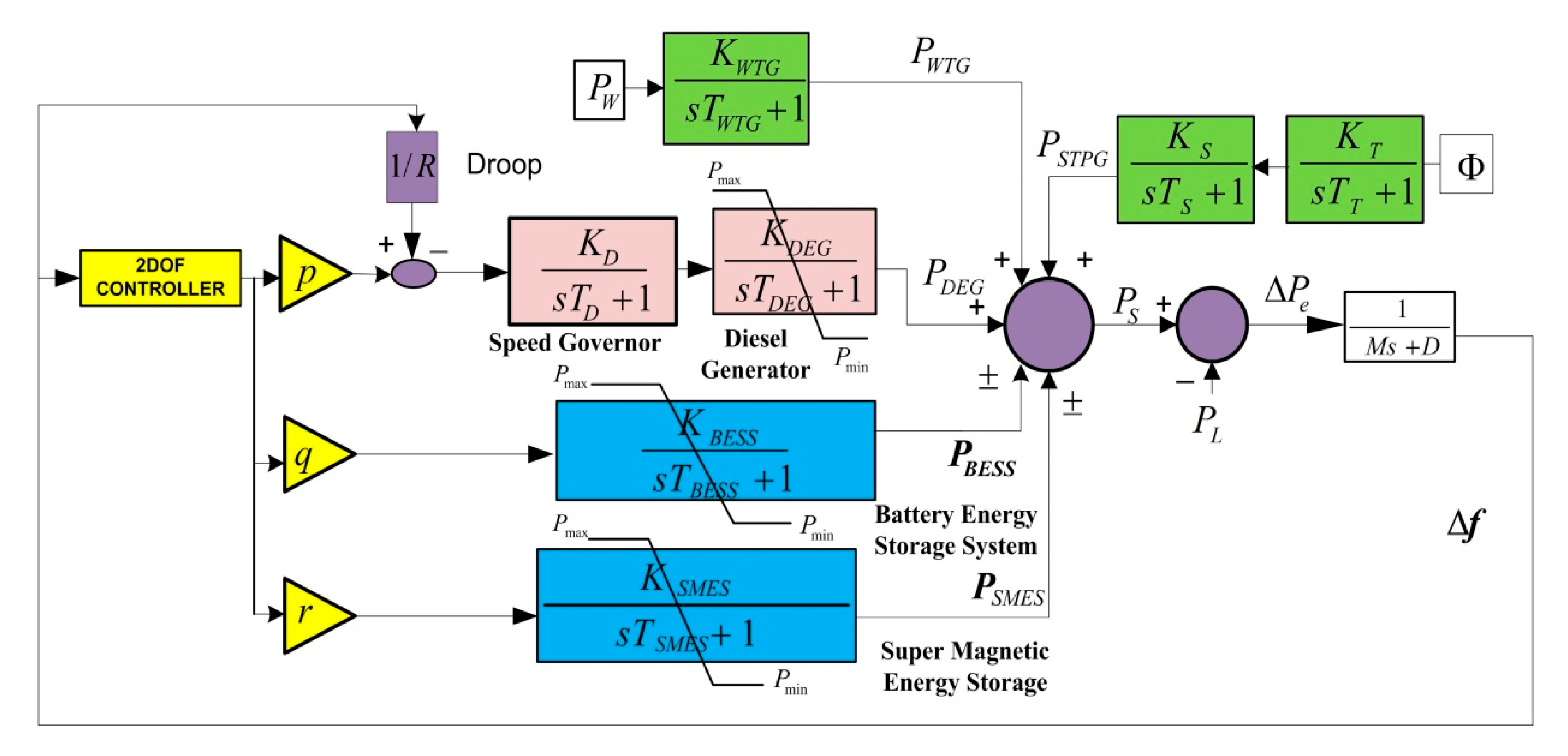
To investigate the dynamic behavior of PI, PID, 2DOF PI, and 2DOF PID controllers in time-domain simulations of a WTG-STPG-DEG-based autonomous hybrid energy system with the following ESS combinations: (i) only BESS, (ii) BESS + UC, and (iii) BESS + SMES.
(b)
To optimize the gains of the PI, PID, 2DOF PI, and 2DOF PID controllers using the heuristic FPA and to investigate their comparative dynamic performance on the proposed system for all three cases.
(c)
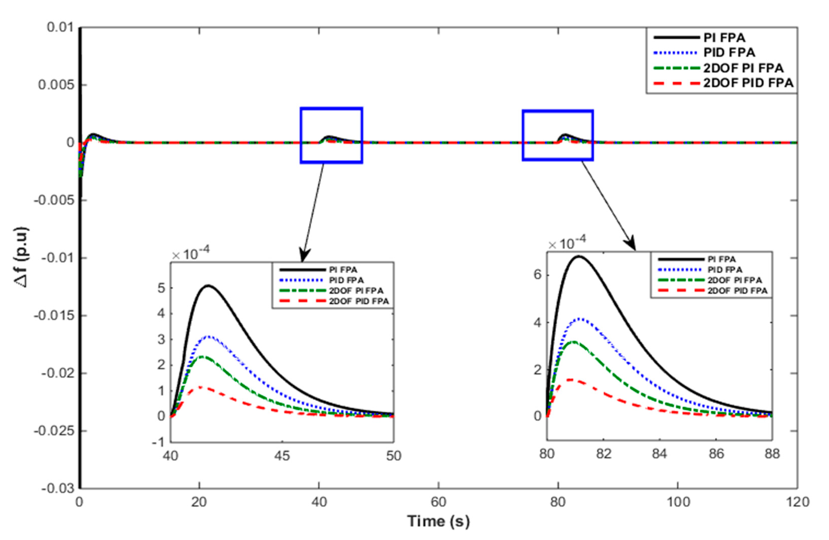
To study the dynamic responses of the FPA-tuned 2DOF PI and 2DOF PID controllers compared with their PI and PID counterparts for regulating the system frequency deviation during the disturbances of the sub-components, i.e., load, renewable power generations, or all of the above cases.
(d)
To compare the performance of the hybrid system model in terms of the frequency deviation in two different energy storage combinations, i.e., UC + BESS-based model compared with a BESS-based model.
(e)
To assess the similar performance between combined use of the SMES + BESS model compared with an only BESS-based hybrid system model.
(f)
Finally, to analyze the performance of the SMES + BESS-based hybrid energy system in contrast to the UC + BESS-based hybrid energy system regarding mitigating power fluctuations.
The rest of the paper is organized as follows: The next section of the proposed assignment deliberated the investigation of the proposed hybrid power model. The problem formulation is discussed in Section 3. The detailed steps of the FPA are illustrated in Section 4. The simulated results for the considered cases are discussed in Section 5 to support the claim and Section 6 briefly concludes the work.

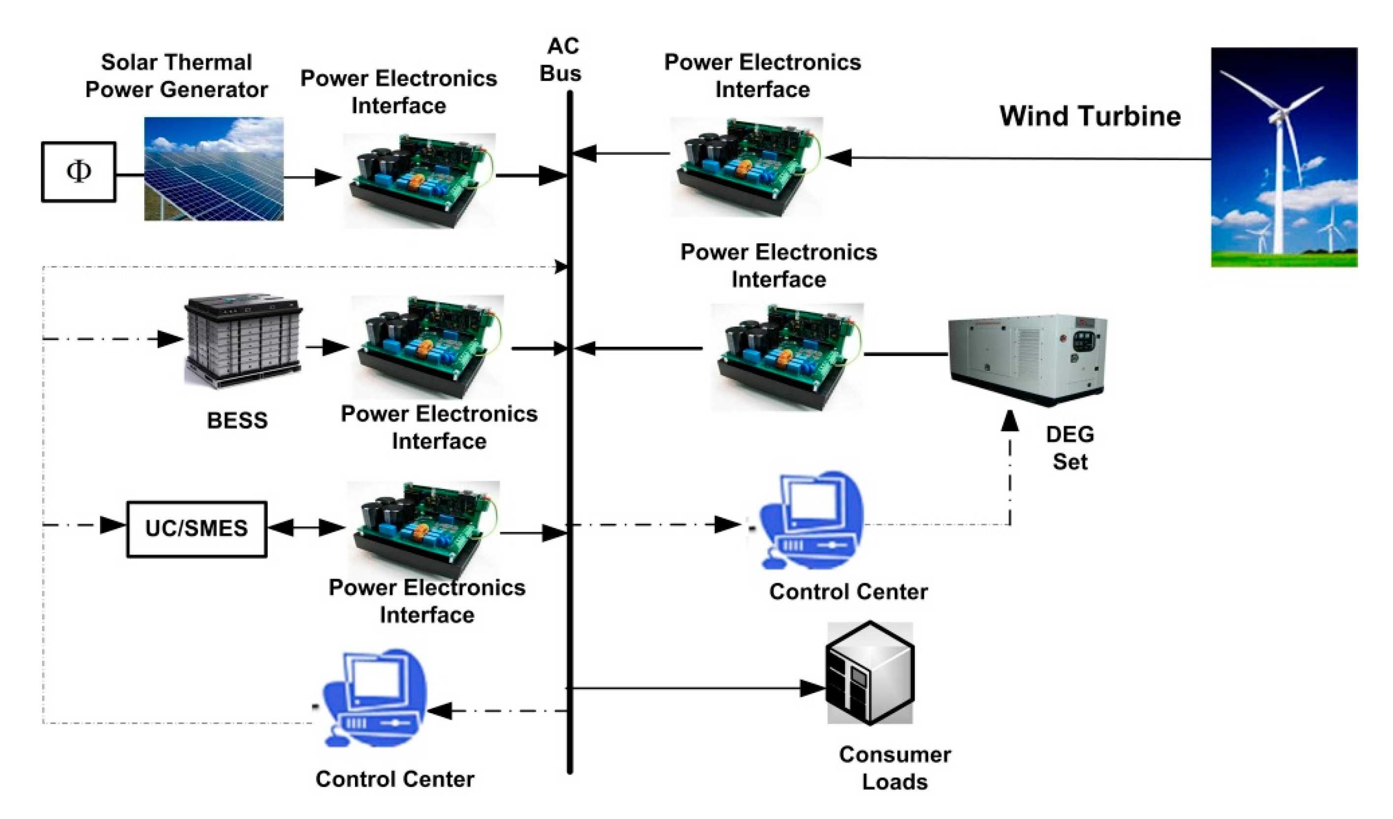
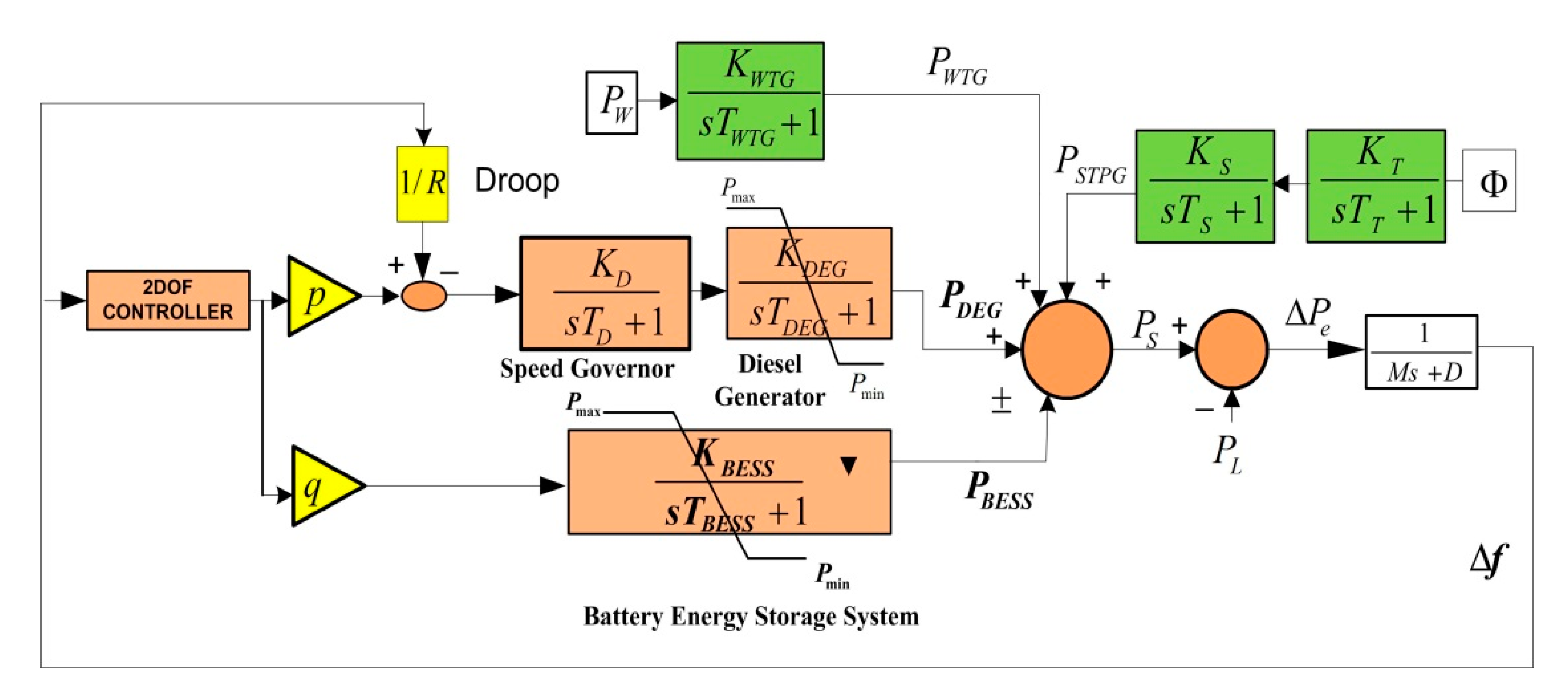
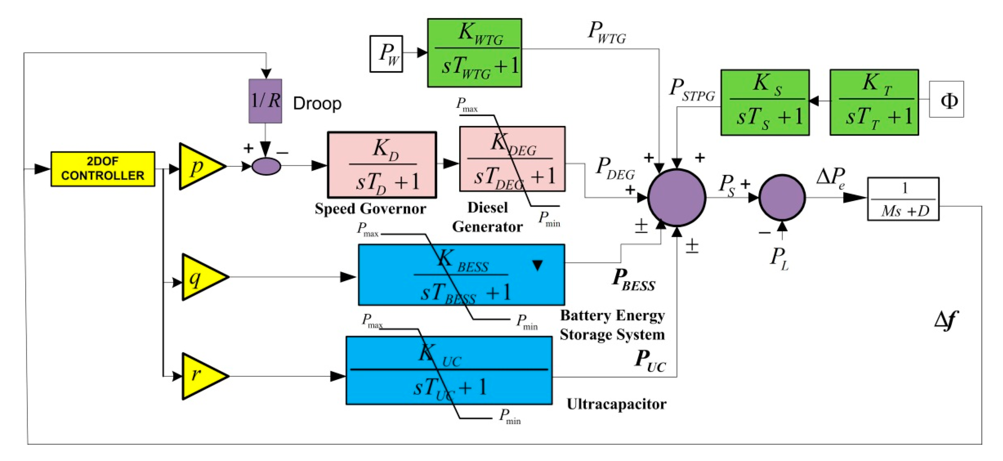
2. Investigated Islanded Hybrid Power System

The WTG–STPG–DEG–BESS–UC/SMES-based islanded hybrid energy system is depicted in Figure 1. The system parameters of the autonomous hybrid system are taken from [7,17,21,24] and are presented in Table 1, along with their generation capacities. An overview of each of the components and their mathematical linearized transfer functions are discussed in [7,8,10,18].

3. Objective Problem Formulation

Any imbalance in the real power generation and demand causes a frequency deviation (Δf). The transfer function hybrid power system in term of f and the mismatch in real power ( Δ P e ) is given by:
G s y s ( s ) = Δ f Δ P e = 1 K s y s ( 1 + s T s y s ) = 1 M s + D ,
where Tsys, M, and D are called the time constant, system inertia, and damping, respectively, of the system.
The control strategy employed with the system ensures the stable operation of the system by making Δf a minimum, if not zero. Therefore, the performance index in terms of Δf is represented by Equation (2):
J = 0 t ( Δ f ) 2 d t ,
subject to the constraints given by the Equations (3)–(7):
K p min K p K p max ,
K i min K i K i max
for PI controllers and:
K p min K p K p max ,
K i min K i K i max ,
K d min K d K d max
for PID controllers, where Kp, Ki, and Kd are the three gain parameters of the PID controller.
In the Matlab R2013a (MathWorks, Natick, Massachusetts, USA) Simulation model of the proposed hybrid power system, three controllers were enabled with generation (DEG) and storage units (SMES, BESS), respectively. During the optimization of the PID control units’ parameters in the frequency response model, the convergence curve J was minimized using the tuned Kp, Ki, and Kd parameters of all three PID control units. For the PI control unit, a similar process was followed by tuning all three PI control units’ Kp and Ki gains. However, in the case of the 2DOF PI controller, in addition to the Kp and Ki parameters, the setpoint b of each of the three controllers was optimized. Similarly, in the case of the 2DOF PID controllers, the Kp, Ki, Kd, b, and c parameters were optimized simultaneously. The ranges of Kp, Ki, Kd, b, and c are presented in Table 2.

4. Flower Pollination Algorithm

The FPA is a newly established powerful metaheuristic tool that is centered on the notion of flower pollination, as proposed by Yang et al. [27]. In this pollination process, the pollen is distributed by interacting the male with the female flower part named the stigma. With a variety of pollinators in an ecosystem, it is assumed that there are almost two hundred diversified pollinators (such as bats, insects, and birds). Generally, two types of pollination are leveraged to process the pollinator: namely, biotic and abiotic processes. The FPA technique leveraged four rules to establish the real interaction process [27]:
(a)
The global pollination approach by enabling two biotic cross-pollinations with the distribution of the pollinators followed by Levy flights.
(b)
Consideration of abiotic self-pollination to lead toward local pollination.
(c)
The reproduction probability of a flower pollination approach is directly proportional to the similarity factor between the two engaged flowers.
(d)
A switching probability factor Ps {0, 1} is utilized to contain the local and global pollination approach.
The detailed concept of the FPA may be found in [26,27,28]. In brief, for this study, the main objective was to find the fitness function in terms of J while optimizing the control parameters using FPA, which was as follows:
fitness i = 1 ( 1 + J )   for   the   i th   population .
The tuned parameters of the FPA technique are shown in Table 3.

5. Results and Analysis

This section investigates the dynamic responses and their assessment of the proposed hybrid power system using time-domain simulations. In contrast to the utilization of separate controllers for different subsystems (generating/storage units), i.e., DEG, BESS, SMES, and UC, a lesser utilized load frequency controller (only one controller) was employed as shown in Figure 2. When the load demand exceeded the sum of the generation from the WTG and STPG, the DEG and ESS catered to the load with proper coordination. Table 4 presents the simulation conditions for the following three case studies.

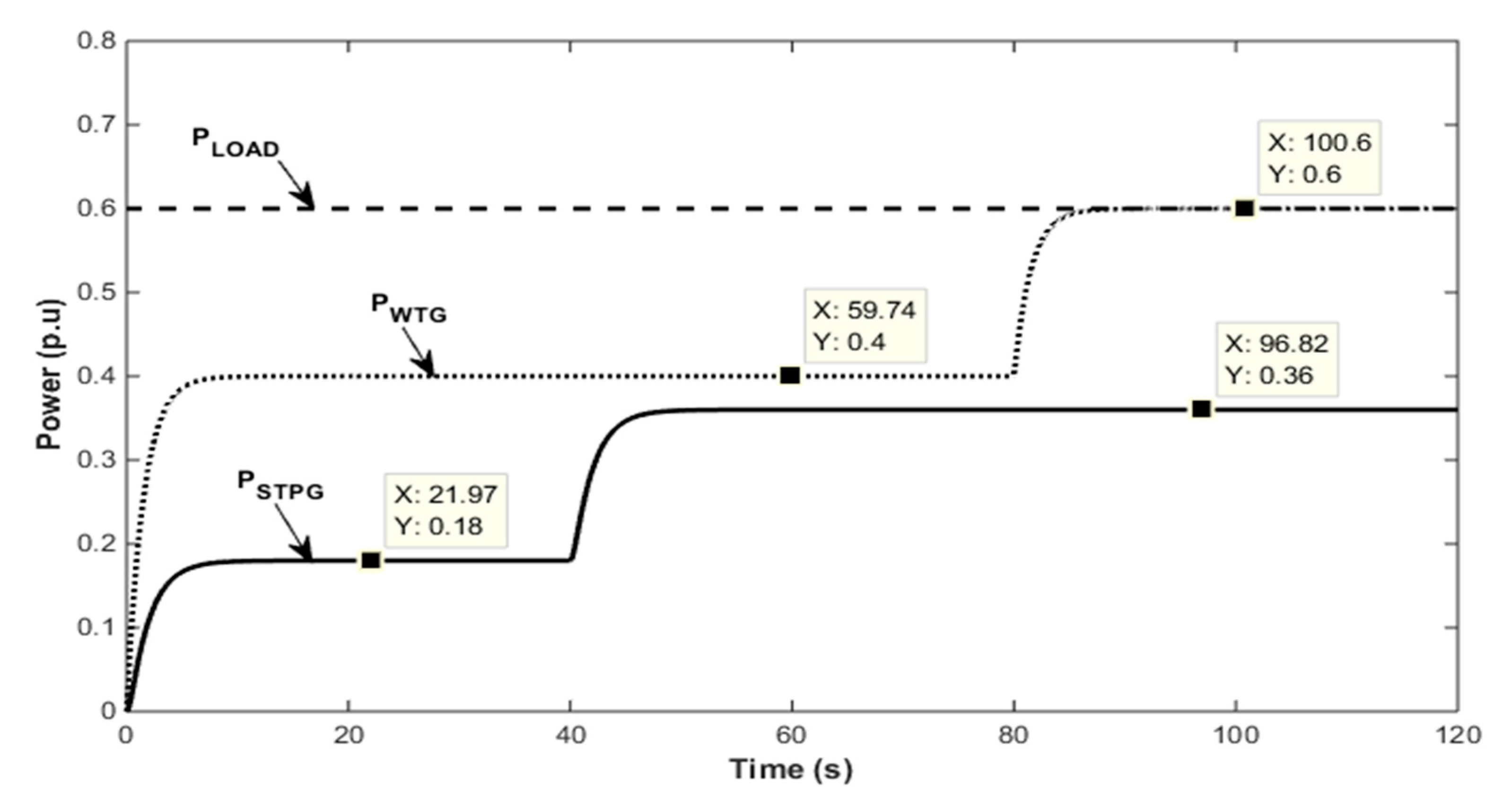
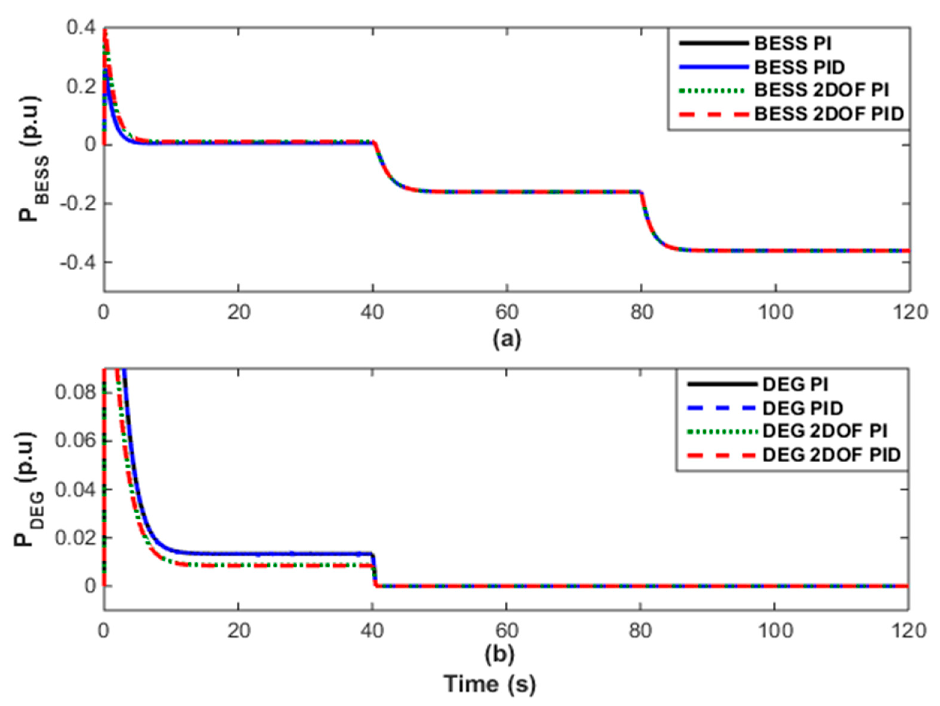
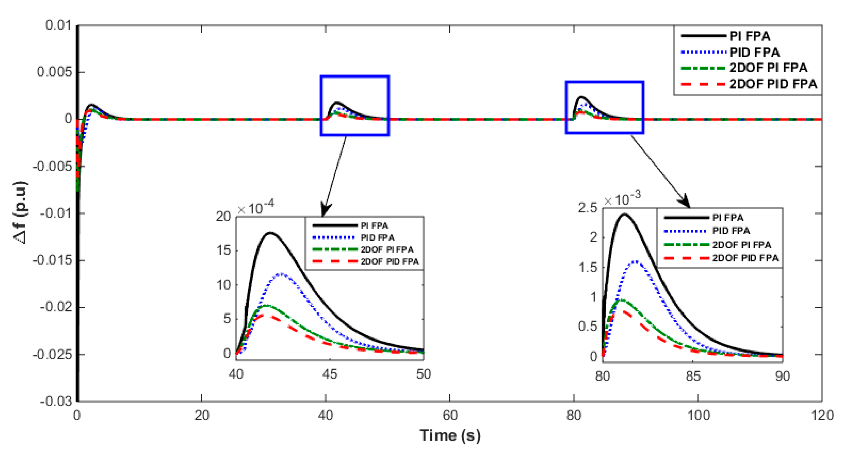
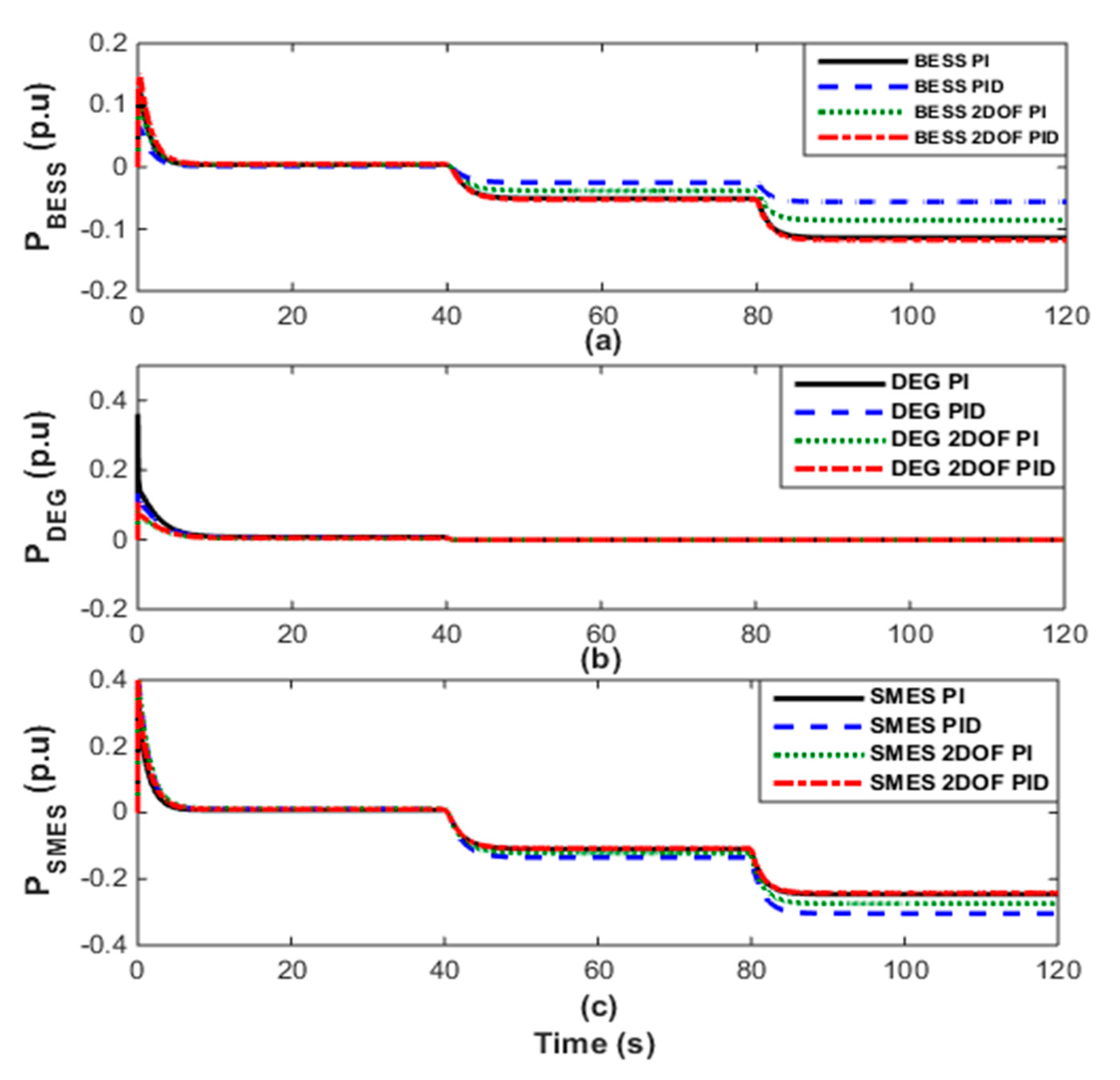
5.1. Time-Domain Response Analysis: Case 1

The linearized model of the WTG–STPG–DEG–BESS-based autonomous hybrid energy network of this case is shown in Figure 2. P W T G and P S T P G were the main power resources of the hybrid energy system, and DEG was expected to provide long-term energy balance, whereas the BESS integration acted as buffer storage for short-term compensation.
The generated power ( P S ) in this scenario can be illustrated by Equation (9):
P S = P W T G + P S T P G + P D E G ± P B E S S .
The power-sharing from the WTG and STPG with a load demand is given in Figure 3. In this base scenario, a constant sharing of 0.6 p.u load power is leveraged. To study the controller responses caused by step disturbances in input powers, the following time-domain analysis was carried out. During 0 < t < 40 s, as shown in Figure 3, the total power generated by the PWTG and PSTPG system was less than the load power-sharing; thus the DEG and BESS units provided the extra power required to balance the load demand. At t = 40 s, the solar P S T P G   increased to 0.36 p.u from its base value of 0.18 p.u due to an increase in solar radiation, and at 80 s, P W T G   was suddenly uplifted to 0.6 p.u from its previous value of 0.4 p.u. During 80 < t < 120 s, the system had surplus generation; hence, there was no power generation from the diesel generator and the BESS started absorbing the excess power (Figure 4).
During the abovementioned uncertainties, the system frequency deviated due to an imbalance in the aggregated generation-load power. The controller integrated into the hybrid energy network automatically regulated the power-sharing of the DEG and BESS to the corresponding values to eliminate the power difference. Finally, the frequency settled down to its base value because of the action of the controllers. The transient response of the frequency deviation observed with the FPA-optimized PI, PID, 2DOF PI, and 2DOF PID controllers are depicted in Figure 5.
From the comparative dynamic responses of the change in frequency fluctuations leveraging the FPA-tuned PI, PID, 2DOF PI, and 2DOF PID controllers, it can be seen that the system dynamics of the FPA-optimized 2DOF PID controller was superior compared to the PI, PID, and 2DOF PI controllers, which was due to decision parameters, such as the peak transient deviation and the settling time.
The optimized gain values of the PI, PID, 2DOF PI, and 2DOF PID controllers attained using the FPA are displayed in Table 5, Table 6, Table 7 and Table 8, respectively.
The maximum frequency deviations (∆f in Hz) of the autonomous hybrid power network for various operating conditions are tabulated in Table 9.

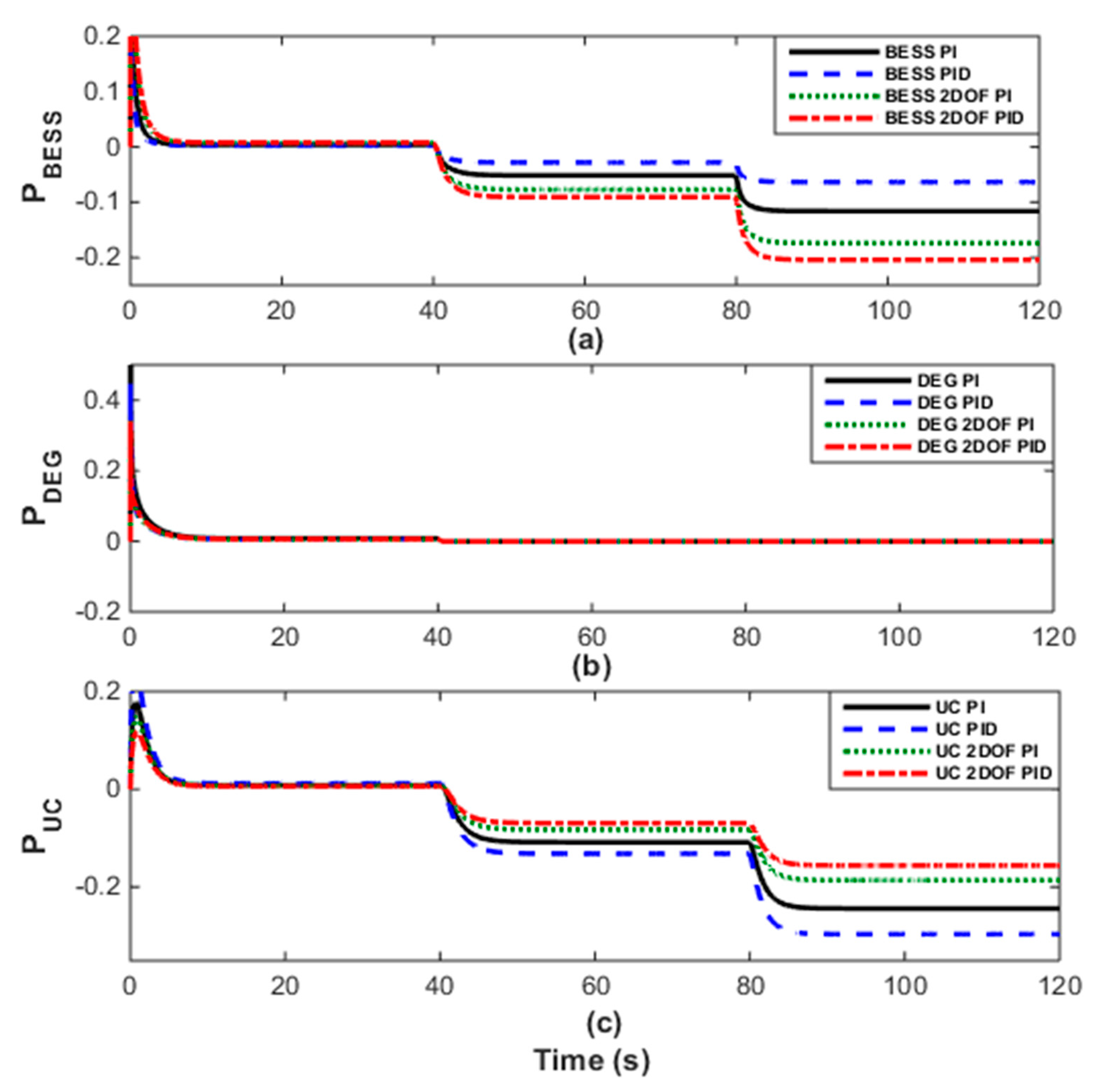
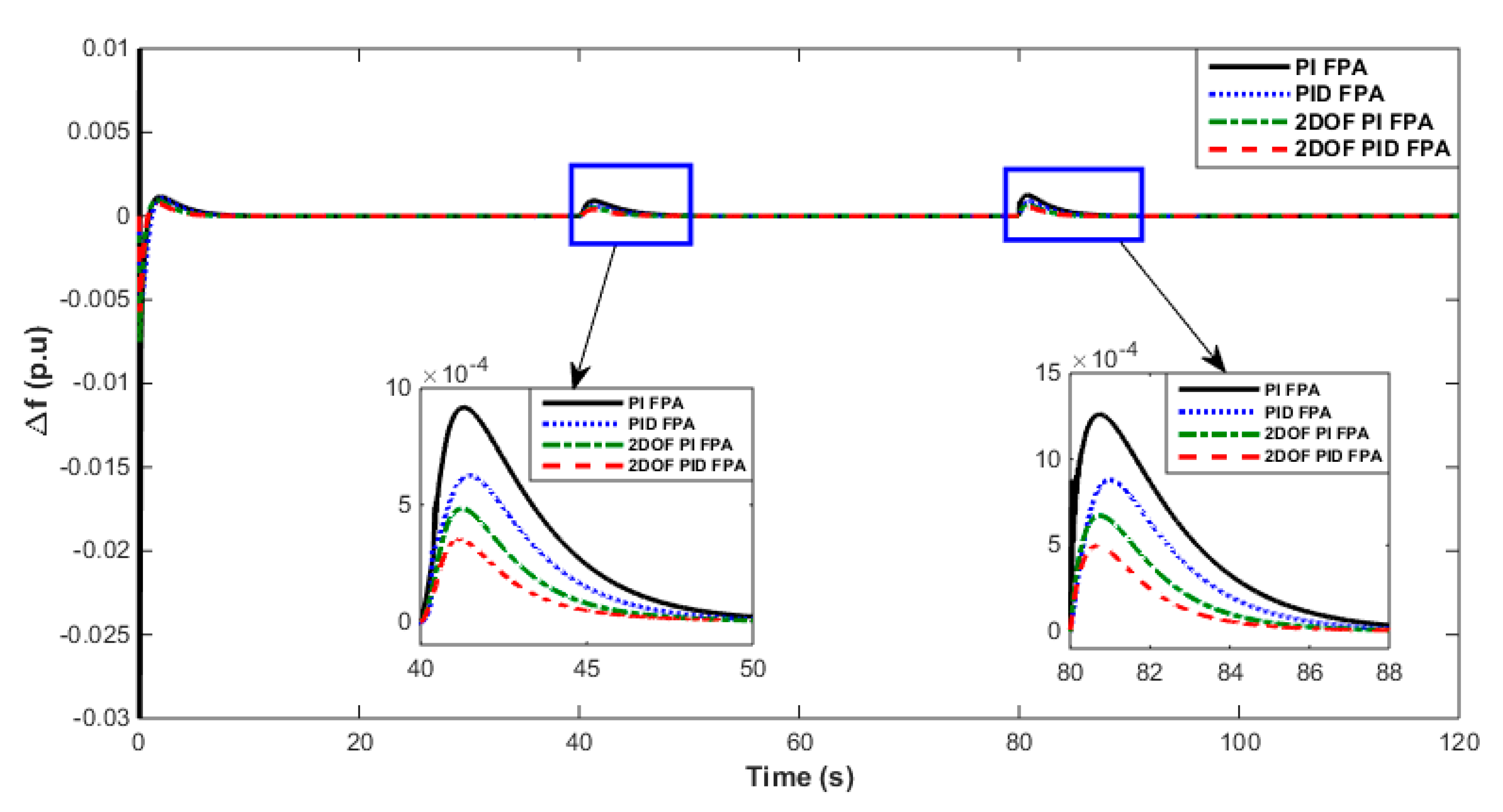
5.2. Time-Domain Response Analysis: Case 2

The transfer function model of the WTG–STPG–DEG–BESS–UC-based islanded hybrid energy network of this case is shown in Figure 6. In this case, PWTG and PSTPG were also the prime power sources of the hybrid energy system, and DEG was expected to provide long-term energy balance, whereas the BESS and UC integration acted as energy storage devices.
The power generation in this case can be expressed by Equation (10):
P S = P W T G + P S T P G + P D E G ± P B E S S ± P U C .
In this case, the loading conditions of the system remained the same as in case 1. Figure 7 shows the output power of (a) BESS, (b) DEG, and (c) UC.
Figure 8 depicts the comparative performance assessment of Δf for the considered case model after leveraging the FPA-optimized PI, PID, 2DOF PI, and 2DOF PID controllers. From the above, it can be concluded that the response of the FPA-optimized 2DOF PID controller was better than the PI, PID, and 2DOF PI controllers considered for this study under disturbed conditions in terms of the peak transient deviation and settling time.
The optimized gain values of the PI, PID, 2DOF PI, and 2DOF PID controllers obtained using the FPA are presented in Table 5, Table 6, Table 7 and Table 8, respectively. The maximum change in frequency deviations (∆f in Hz) of the hybrid response model for various operating conditions are shown in Table 9.

5.3. Time-Domain Response Analysis: Case 3

The transfer function model of the WTG–STPG–DEG–BESS–SMES-based autonomous hybrid energy system of this case is shown in Figure 9. In this case, PWTG and PSTPG were also the primary power sources of the hybrid energy system, and DEG was expected to provide the long-term energy balance, whereas the BESS and SMES integration acted as energy storage devices.
The generated power in this scenario could be described by Equation (11):
P S = P W T G + P S T P G + P D E G ± P B E S S ± P S M E S .
In this case, the loading conditions of the system remained the same as in case 1. Figure 10 shows the output power of the (a) BESS, (b) DEG, and (c) SMES.
Figure 11 depicts the comparative performance assessment of Δf for the considered case model after leveraging the FPA-tuned PI, PID, 2DOF PI, and 2DOF PID controllers. From the above, it can be concluded that the response of the FPA-optimized 2DOF PID controller under the disturbed conditions performed better than the PI, PID, and 2DOF PI controller units, which was due to decision parameters such as the peak transient deviation and settling time.
The optimized gain values of the PI, PID, 2DOF PI, and 2DOF PID controllers attained using the FPA are displayed in Table 5, Table 6, Table 7 and Table 8, respectively. The maximum changes in the frequency fluctuations (∆f in Hz) of the hybrid response model for different operating conditions are shown in Table 9.

5.4. Comparative Performance of the Frequency Responses of the Above Three Cases

In this section, the comparative performance in mitigating the frequency fluctuations was carried out for three cases: (i) only BESS, (ii) BESS + UC, and (iii) BESS + SMES.

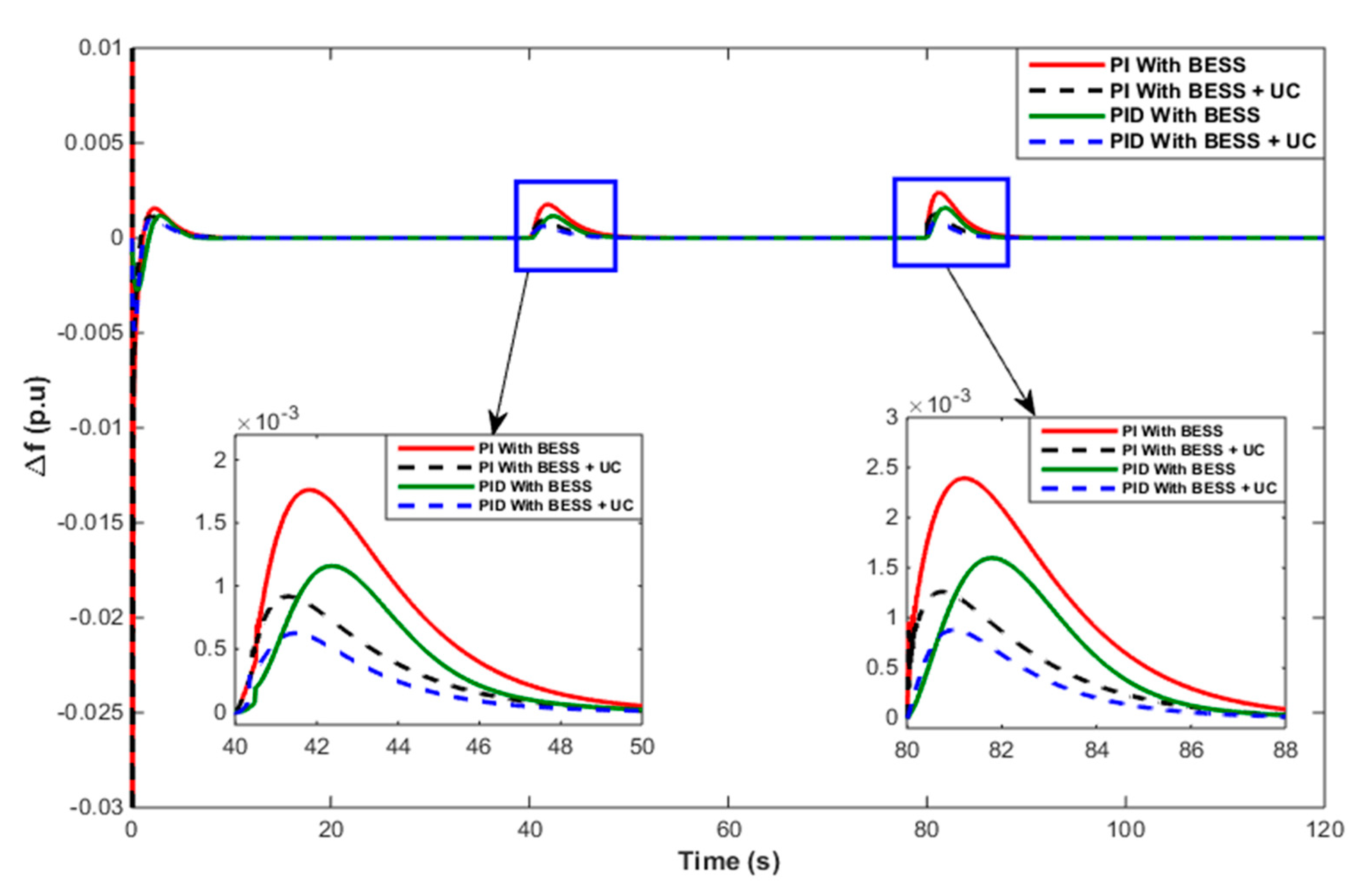
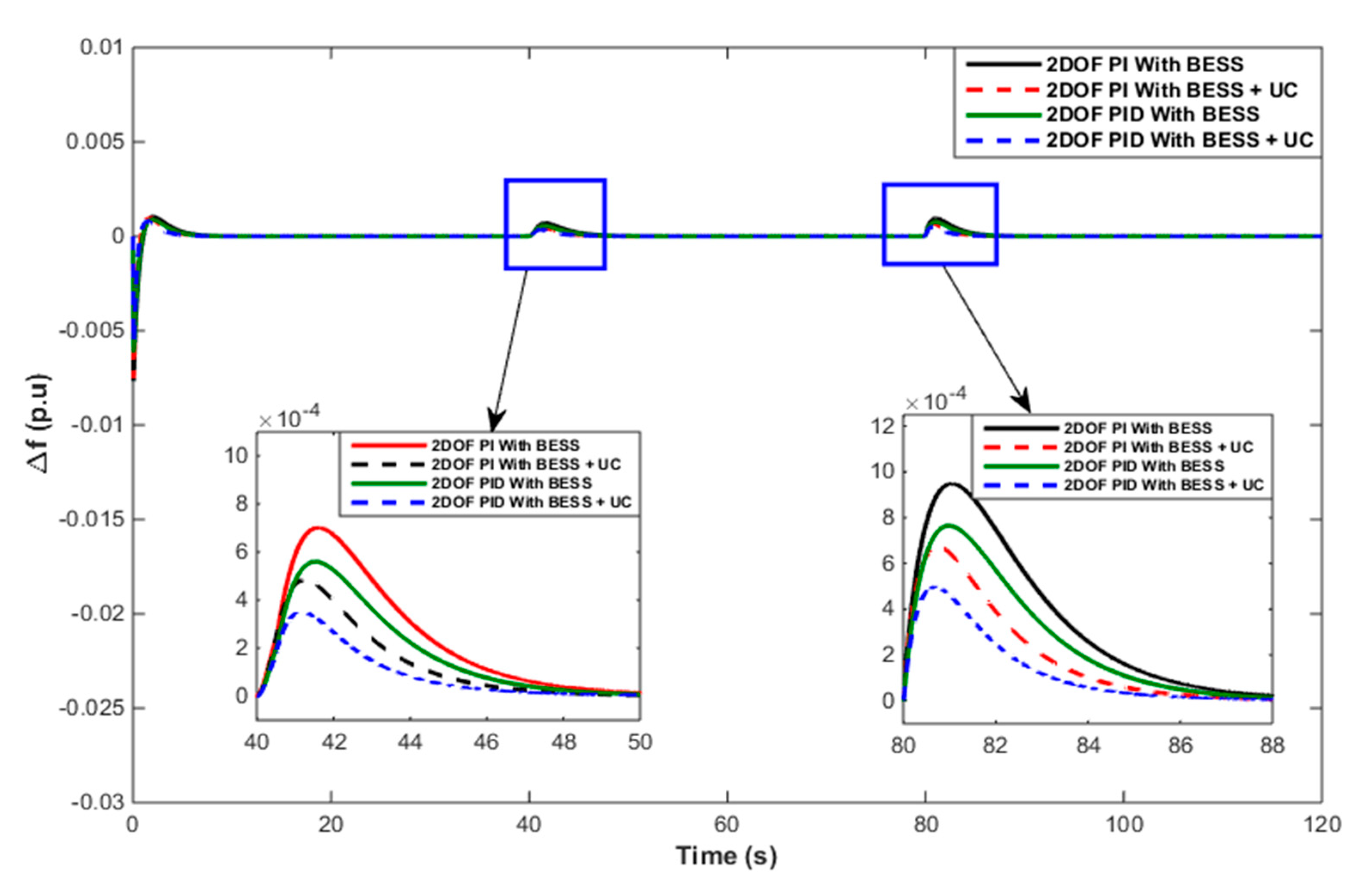
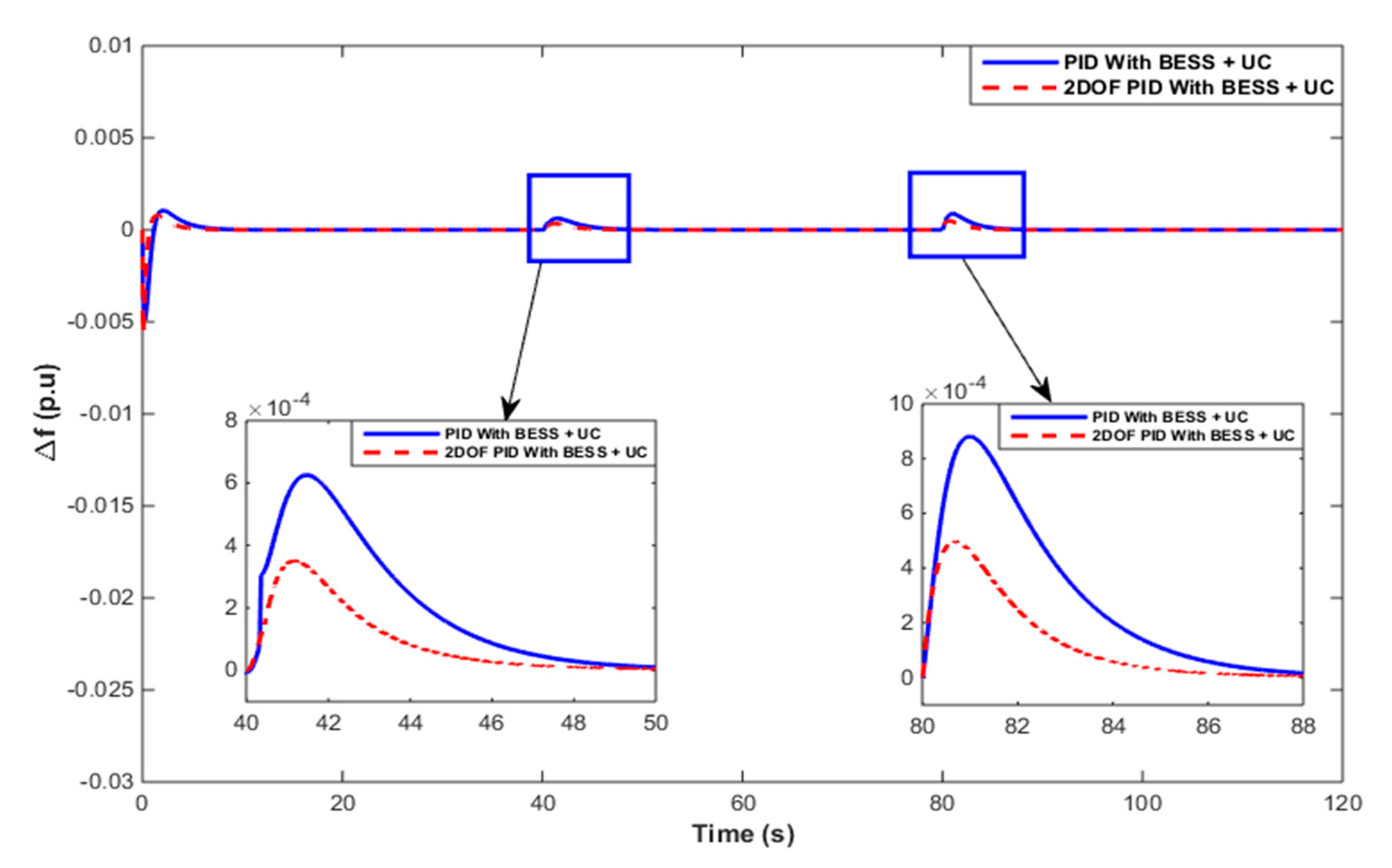
5.4.1. Frequency Response of BESS (Case 1) vs. BESS + UC (Case 2)

The comparative assessment of the frequency deviation for the BESS and BESS + UC hybrid energy systems using the PI and PID controllers is given in Figure 12, while that using the 2DOF PI and 2DOF PI PID controllers is shown in Figure 13. Figure 14 illustrates the comparative performance of the PID and 2DOF PID controllers.
It may be observed that the combined use of UC and BESS performed better than using only a BESS-based hybrid energy system and provided better frequency control in the hybrid energy system. Moreover, the performance assessment of the different controllers engaged in the energy storage revealed the superiority of the 2DOF PID controller against other combinations of controllers. The frequency deviation and setting time observed in these figures and in Table 9 (for Δf) confirmed the superiority of the 2DOF PID control strategy.

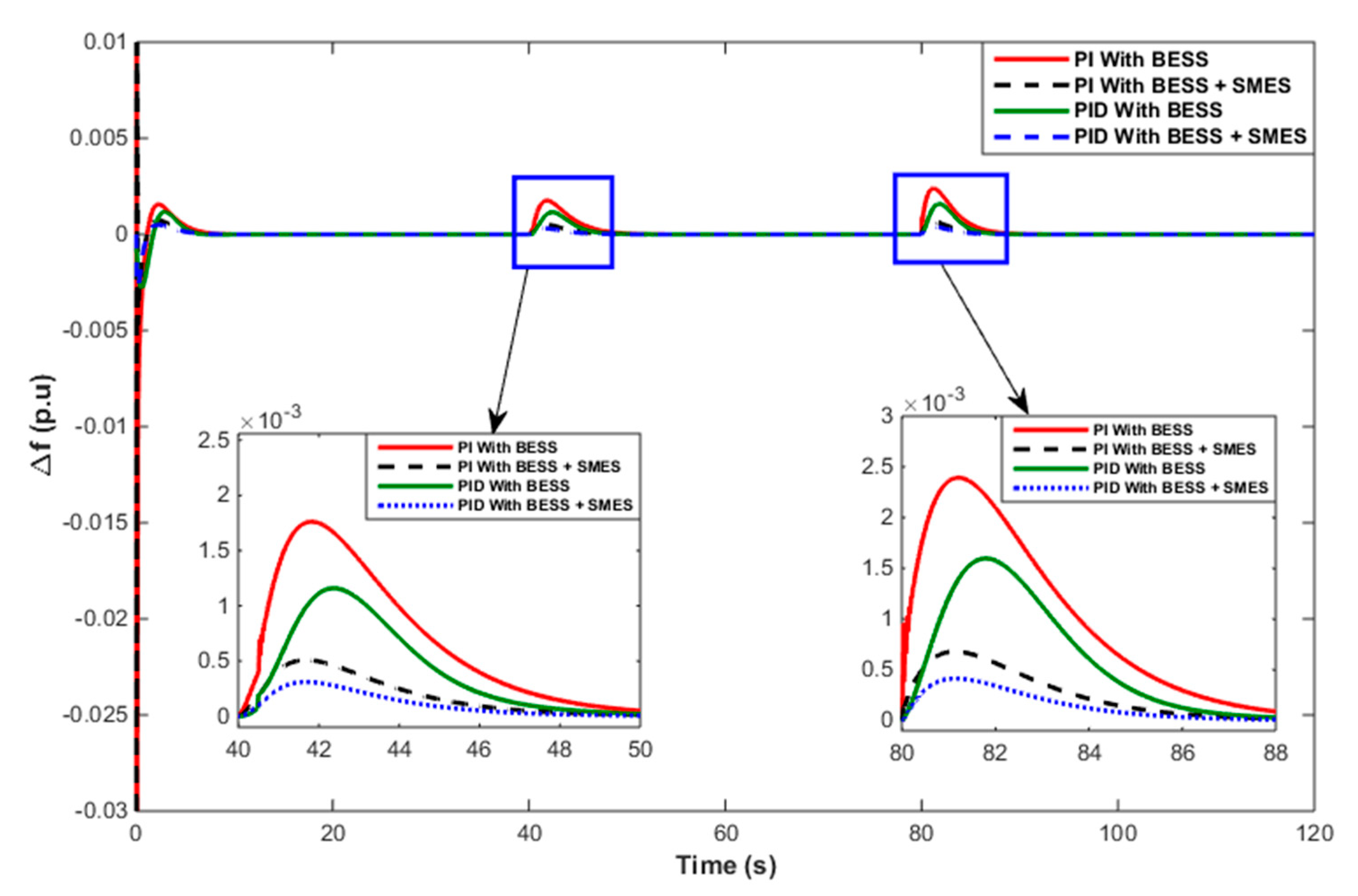
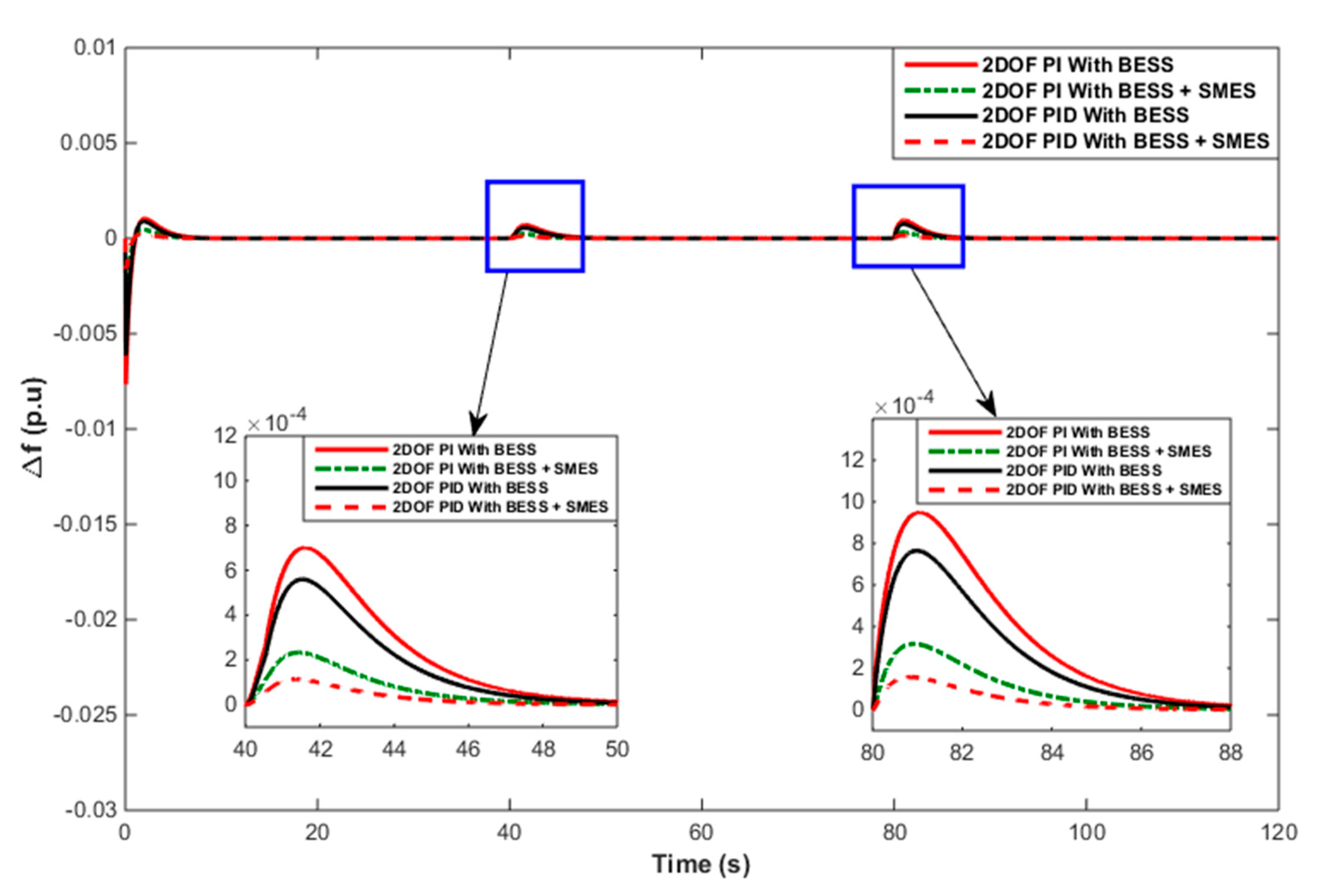
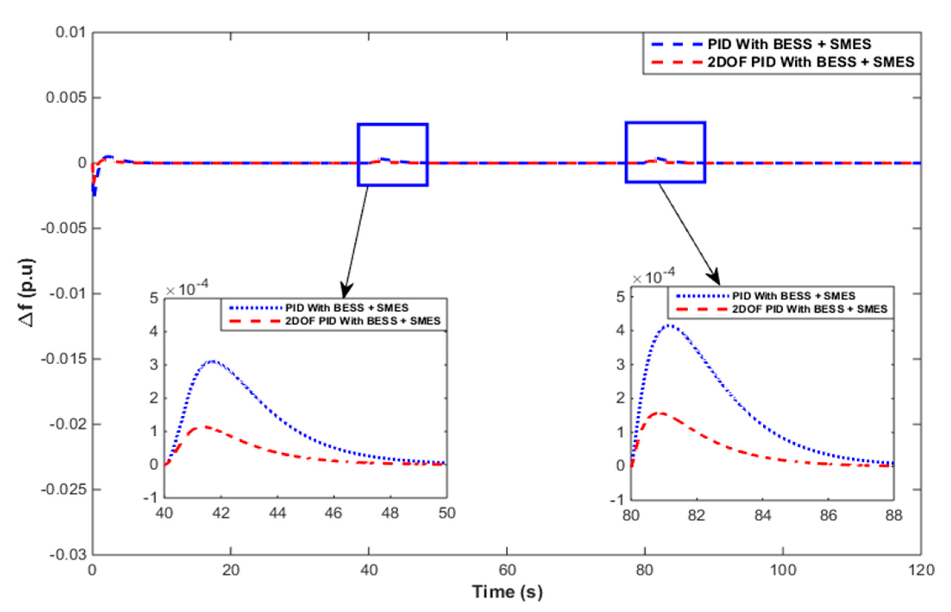
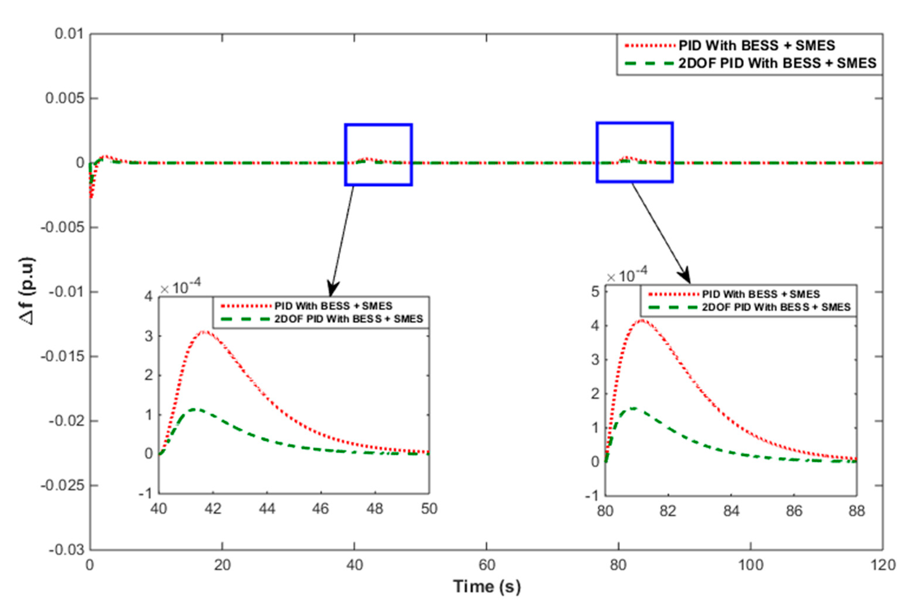
5.4.2. Frequency Response of BESS (Case 1) vs. BESS + SMES (Case 3)

The comparative assessment of the frequency fluctuation for the BESS and BESS + SMES hybrid energy systems using PI and PID controllers are provided in Figure 15, while that using the 2DOF PI and 2DOF PID controllers are shown in Figure 16. Figure 17 illustrates the comparative performances when using the PID and 2DOF PID controllers.
It may be observed that the combined use of SMES and BESS performed better than the only BESS-based hybrid energy system and caused better frequency control in the hybrid energy system. In fact, the performance assessment of different controllers engaged with the energy storage systems revealed the superiority of the 2DOF PID relative to the other combinations of controllers. The frequency deviation and setting time observed in Figure 15, Figure 16 and Figure 17 and in Table 9 (for Δf) confirmed the superiority of the 2DOF PID control strategy.

5.4.3. Frequency Response of BESS + UC (Case 2) vs. BESS + SMES (Case 3)

The comparative assessment of the frequency deviations for the BESS + UC and BESS + SMES hybrid energy systems using PI and PID controllers is provided in Figure 18, while that using the 2DOF PI and 2DOF PID controllers are depicted in Figure 19. Figure 20 illustrates the comparative performances when using the PID and 2DOF PID controllers. It may be observed that the combined use of SMES and BESS performed better than the BESS + UC-based hybrid energy system and caused better frequency control in the hybrid energy system. Moreover, the performance assessment of different controllers engaged in the energy storage revealed the superiority of the 2DOF PID controller against other storage combinations of enabled controllers.
Thus, the comparative assessment of frequency deviations for the hybrid energy systems revealed that the combined use of UC + BESS performed better than the only BESS-based hybrid energy system and caused better frequency control in the hybrid energy system. Furthermore, the combined use of SMES + BESS demonstrated better performance than the only BESS-based hybrid energy system. Finally, it was observed that the performance of the SMES + BESS-based hybrid energy system was more effective than the UC + BESS-based hybrid energy system at mitigating power fluctuations and achieved better frequency control in the hybrid energy system.

6. Conclusions

An islanded hybrid power system consisting of an ORC low-temperature solar thermal system, wind turbine generator, diesel engine generator, and the combined application of various energy storage systems was investigated for the first time. Furthermore, the hybrid system was employed with a single controller (any of the PI, PID, 2DOF PI, and 2DOF PID controllers) with proportionate gains to the DEG and the ESS, which is another unique aspect of this work. Moreover, a comparative performance assessment of the FPA-tuned PI, PID, 2DOF PI, and 2DOF PID controllers was carried out for three case studies. Finally, the performance of the above hybrid system was compared with different ESS combinations, namely, (i) only BESS, (ii) BESS + UC, and (iii) BESS + SMES. The simulation results indicated the following:
(a)
It was observed that the response of the FPA-optimized 2DOF PID controller was superior to the PI, PID, and 2DOF-PI controllers due to decision parameters such as the peak transient deviation and settling time.
(b)
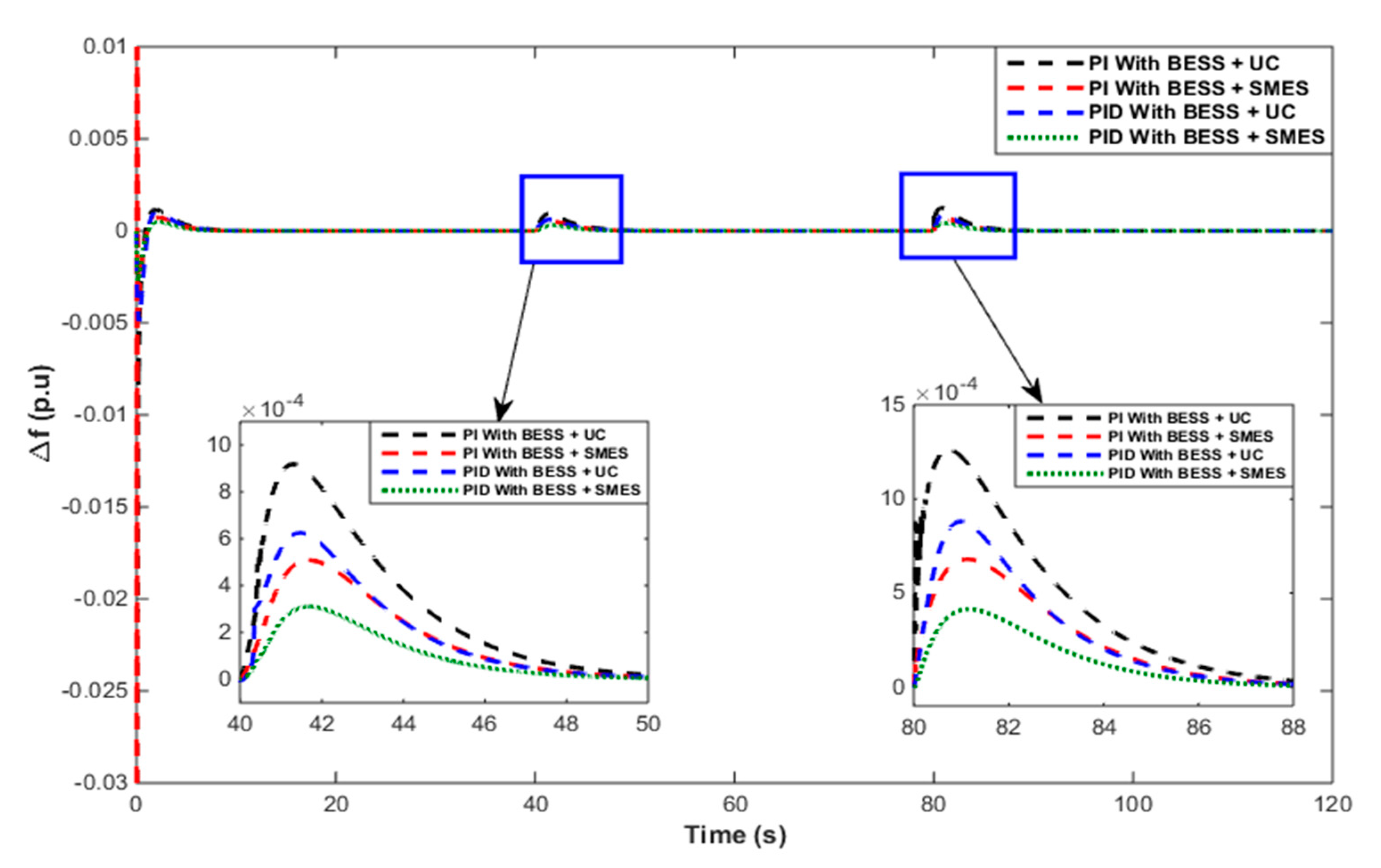
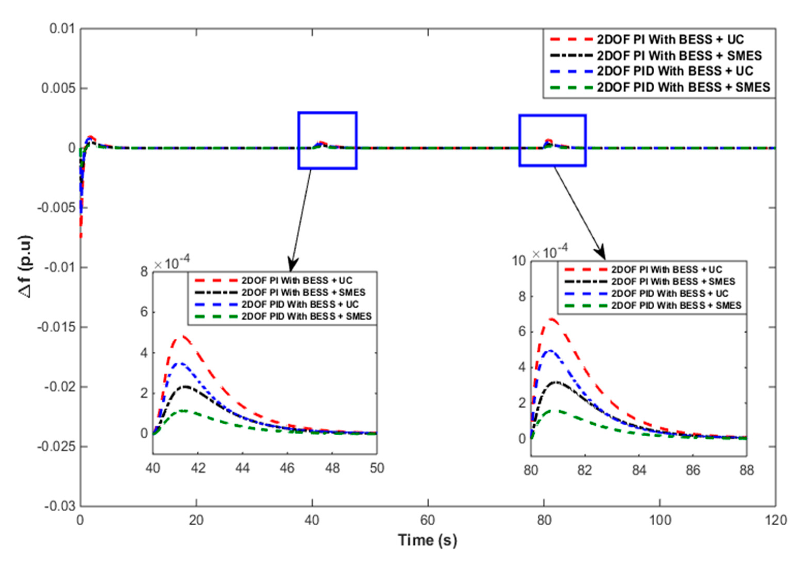
The assessment of the responses of the hybrid system model for only BESS compared with UC + BESS under the same operating conditions showed that the UC + BESS-based hybrid system model performed better than the only BESS-based model. At the same time, the 2DOF PID controller provided a superior result compared with the other controllers.
(c)
Furthermore, the comparative performances of the only BESS-based hybrid system model against the SMES + BESS-based hybrid system model under the same operating conditions indicated that the SMES + BESS-based hybrid system model performed better than the only BESS-based model. Furthermore, the 2DOF PID controller performed better than the other controllers.
(d)
However, the comparative performances of the BESS + UC-based hybrid system model against the SMES + BESS-based hybrid system model under the same operating conditions revealed that the SMES + BESS-based hybrid system model performed better than the BESS + UC-based model. Here, the performance assessment of the various controllers revealed the superiority of the 2DOF PID controller.
(e)
It was observed that the response of the FPA-optimized 2DOF PID controller was superior compared with the PI, PID, and 2DOF PI controllers due to decision parameters such as the peak transient deviation and settling time.
(f)
Finally, it was concluded that despite uncertainties or disturbances in the input due to the wind or the ORC low-temperature solar thermal system, a single controller with appropriate gains could maintain the system frequency within the acceptable limits. The use of a single controller is expected to reduce the costs while preserving the stability and reliability of the supply and system.
Our future study will include a comparative performance of the hybrid system model employed with other recent optimization-algorithm-based controllers.

Author Contributions

Conceptualization, I.H., D.C.D., N.S. and A.L.; methodology, I.H., D.C.D., N.S. and A.L.; software, I.H. and A.L.; validation, I.H. and A.L.; formal analysis, I.H., D.C.D., N.S., A.L., S.M.S.H. and T.S.U.; investigation, I.H., A.L. and S.M.S.H.; resources, D.C.D., S.M.S.H. and T.S.U.; data curation, I.H., D.C.D., and A.L.; writing--original draft preparation, I.H. and D.C.D., writing--review and editing, A.L., S.M.S.H. and T.S.U.; visualization, I.H. and A.L.; supervision, D.C.D. and N.S.; project administration, D.C.D., S.M.S.H. and T.S.U.; funding acquisition, S.M.S.H. and T.S.U.; All authors have read and agreed to the published version of the manuscript.

Funding

This research received no external funding.

Acknowledgments

Authors would like to thank Technical Education Quality Improvement Programme (TEQIP)-III, National Institute of Technology Silchar for providing technical support for this work.

Conflicts of Interest

The authors declare no conflict of interest.

Abbreviations

ORCOrganic Rankine cycle
ESSEnergy storage system
UCUltracapacitor unit
WTGWind generator
BESSBattery
SMESSuper magnetic energy storage
2DOFTwo-degree-of-freedom
STPGSolar thermal power generation
FPAFlower pollination algorithm
DEGDiesel generation
PIProportional-integral
PIDProportional-integral-derivative
ΔfChange in frequency deviation
JObjective function

References

  1. Almeshqab, F.; Ustun, T.S. Lessons learned from rural electrification initiatives in developing countries: Insights for technical, social, financial and public policy aspects. Renew. Sustain. Energy Rev. 2019, 102, 35–53. [Google Scholar] [CrossRef]
  2. Quoilin, S.; Orosz, M.; Hemond, H.; Lemort, V. Performance and design optimization of a low-cost solar organic Rankine cycle for remote power generation. Sol. Energy 2011, 85, 955–966. [Google Scholar] [CrossRef] [Green Version]
  3. Tchanche, B.F.; Lambrinos, G.; Frangoudakis, A.; Papadakis, G. Low-grade heat conversion into power using organic Rankine cycles-A review of various applications. Renew. Sustain. Energy Rev. 2011, 15, 3963–3979. [Google Scholar] [CrossRef]
  4. Tocci, L.; Pal, T.; Pesmazoglou, I.; Franchetti, B. Small Scale Organic Rankine Cycle (ORC): A Techno-Economic Review. Energies 2017, 10, 413. [Google Scholar] [CrossRef]
  5. Nadeem, F.; Hussain, S.M.S.; Tiwari, P.K.; Goswami, A.K.; Ustun, T.S. Comparative Review of Energy Storage Systems, Their Roles, and Impacts on Future Power Systems. IEEE Access 2019, 7, 4555–4585. [Google Scholar] [CrossRef]
  6. Das, D.C.; Roy, A.K.; Sinha, N. GA based frequency controller for solar thermal–diesel–wind hybrid energy generation/energy storage system. Int. J. Electr. Power Energy Syst. 2012, 43, 262–279. [Google Scholar] [CrossRef]
  7. Latif, A.; Pramanik, A.; Das, D.C.; Hussain, I.; Ranjan, S. Plug in hybrid vehicle-wind-diesel autonomous hybrid power system: Frequency control using FA and CSA optimized controller. Int. J. Syst. Assur. Eng. Manag. 2018, 9, 1147–1158. [Google Scholar] [CrossRef]
  8. Barik, A.; Das, D.C. Expeditious frequency control of solar photobiotic/biogas/biodiesel generator based isolated renewable microgrid using grasshopper optimisation algorithm. IET Renew. Power Gener. 2018, 12, 1659–1667. [Google Scholar] [CrossRef]
  9. Javed, K.; Ashfaq, H.; Singh, R.; Hussain, S.M.S.; Ustun, T.S. Design and Performance Analysis of a Stand-alone PV System with Hybrid Energy Storage for Rural India. Electronics 2019, 8, 952. [Google Scholar] [CrossRef] [Green Version]
  10. Ranjan, S.; Das, D.C.; Behera, S.; Sinha, N. Parabolic trough solar–thermal–wind–diesel isolated hybrid power system: Active power/ frequency control analysis. IET Renew. Power Gener. 2018, 12, 1893–1903. [Google Scholar] [CrossRef]
  11. Latif, A.; Hussain, S.M.S.; Das, D.C.; Ustun, T.S. Optimum Synthesis of a BOA Optimized Novel Dual-Stage PI − (1 + ID) Controller for Frequency Response of a Microgrid. Energies 2020, 13, 3446. [Google Scholar] [CrossRef]
  12. Onar, O.C.; Uzunoglu, M.; Alam, M.S. Modeling, control and simulation of an autonomous wind turbine/photovoltaic/fuel cell/ultra-capacitor hybrid power system. J. Power Sources 2008, 185, 1273–1283. [Google Scholar] [CrossRef]
  13. Uzunoglu, M.; Onar, O.C.; Alam, M.S. Modeling, control and simulation of a PV/FC/UC based hybrid power generation system for stand-alone applications. Renew. Energy 2009, 34, 509–520. [Google Scholar] [CrossRef]
  14. Tammineedi, C. Modeling Battery-Ultracapacitor Hybrid Systems for Solar. Ph.D. Thesis, The Pennsylvania State University, State College, PA, USA, 2011. [Google Scholar]
  15. Lin, W.; Zheng, C. Energy management of a fuel cell/ultracapacitor hybrid power system using an adaptive optimal-control method. J. Power Sources 2011, 196, 3280–3289. [Google Scholar] [CrossRef]
  16. Shin, D.; Kim, Y.; Seo, J.; Chang, N.; Wang, Y.; Pedram, M. Battery-supercapacitor hybrid system for high-rate pulsed load applications. In Design, Automation & Test in Europe Conference & Exhibition; IEEE: Piscataway Township, NJ, USA, 2011; pp. 1–4. [Google Scholar]
  17. Singh, V.P.; Mohanty, S.R.; Kishor, N.; Ray, P.K. Robust H-infinity load frequency control in hybrid distributed generation system. Int. J. Electr. Power Energy Syst. 2013, 46, 294–305. [Google Scholar] [CrossRef]
  18. Attia, A.E.F.; Mohammed, A.E.H. Efficient frequency controllers for autonomous two-area hybrid microgrid system using social-spider optimizer. IET Gener. Transm. Distrib. 2017, 11, 637–648. [Google Scholar]
  19. Mazurenko, I.; Pavlyuk, A.; Vasetsky, Y. Application of superconducting magnetic energy storage (SMES) in electric power grids. In Proceedings of the Computational Problems of Electrical Engineering (CPEE), 2015 16th International Conference on IEEE, Lviv, Ukraine, 2–5 September 2015; pp. 113–115. [Google Scholar]
  20. Das, D.C.; Sinha, N.; Roy, A.K. Small signal stability analysis of dish-Stirling solar thermal based autonomous hybrid energy system. Int. J. Electr. Power Energy Syst. 2014, 63, 485–498. [Google Scholar] [CrossRef]
  21. Ghanamijaber, M. A hybrid fuzzy-PID controller based on gray wolf optimization algorithm in power system. Evol. Syst. 2019, 10, 273–284. [Google Scholar] [CrossRef]
  22. Tungadio, D.H.; Bansal, R.C.; Siti, M.W. Optimal control of active power of two micro-grids interconnected with two AC tie-lines. Electr. Power Compon. Syst. 2017, 45, 2188–2199. [Google Scholar] [CrossRef]
  23. Lal, D.K.; Barisal, A.K.; Tripathy, M. Load Frequency Control of Multi Area Interconnected Microgrid Power System using Grasshopper Optimization Algorithm Optimized Fuzzy PID Controller. In Proceedings of the Recent Advances on Engineering, Technology and Computational Sciences (RAETCS), Allahabad, India, 6–8 February 2018; pp. 1–6. [Google Scholar]
  24. Das, D.C.; Sinha, N.; Roy, A.K. Automatic Generation Control of an Organic Rankine Cycle Solar-Thermal/Wind-Diesel Hybrid Energy System. Energy Technol. 2014, 2, 721–731. [Google Scholar] [CrossRef]
  25. Dash, P.; Saikia, L.C.; Sinha, N. Comparison of performances of several FACTS devices using Cuckoo search algorithm optimized 2DOF controllers in multi-area AGC. Int. J. Electr. Power Energy Syst. 2015, 65, 316–324. [Google Scholar] [CrossRef]
  26. Yang, X.S. Flower pollination algorithm for global optimization. In International Conference on Unconventional Computing and Natural Computation; Springer: Berlin/Heidelberg, Germany, 2012; pp. 240–249. [Google Scholar]
  27. Yang, X.S.; Karamanoglu, M.; He, X. Multi-objective flower algorithm for optimization. Procedia Comput. Sci. 2013, 18, 861–868. [Google Scholar] [CrossRef] [Green Version]
  28. Peesapati, R.; Yadav, V.K.; Kumar, N. Flower pollination algorithm based multi-objective congestion management considering optimal capacities of distributed generations. Energy 2018, 147, 980–994. [Google Scholar] [CrossRef]
Figure 1. Conceptual wind–solar thermal power generation (STPG)–diesel–battery energy storage system (BESS)–ultracapacitor (UC)/super magnetic energy storage (SMES)-based autonomous hybrid energy system.
Energies 13 05610 g001
Figure 2. Linearized frequency response model consisting of a wind generation (WTG)–STPG–diesel generation (DEG)–BESS-based autonomous hybrid energy system.
Energies 13 05610 g002
Figure 3. Power-sharing between a wind generator, solar thermal power system, and load in case 1.
Energies 13 05610 g003
Figure 4. Power-sharing of the (a) BESS and (b) DEG in case 1.
Energies 13 05610 g004
Figure 5. Comparative changes in the frequency deviations observed with the FPA-tuned proportional-integral (PI), PI with derivative (PID), two-degree-of-freedom (2DOF) PI, and 2DOF PID controllers in case 1.
Energies 13 05610 g005
Figure 6. Linearized frequency response model consisting of a WTG–STPG–DEG–BESS–UC-based autonomous hybrid energy system.
Energies 13 05610 g006
Figure 7. Output power of the (a) BESS, (b) DEG, and (c) UC in case2.
Energies 13 05610 g007
Figure 8. Comparative changes in the frequency deviations observed with the FPA-tuned PI, PID, 2DOF PI, and 2DOF PID controllers in case 2.
Energies 13 05610 g008
Figure 9. Linearized frequency response model of the WTG–STPG–DEG–BESS–SMES integrated autonomous hybrid energy network.
Energies 13 05610 g009
Figure 10. Power-sharing of the (a) BESS, (b) DEG, and (c) SMES in case3.
Energies 13 05610 g010
Figure 11. Comparative changes in the frequency deviations observed with the FPA-optimized PI, PID, 2DOF PI, and 2DOF PID controllers in case 3.
Energies 13 05610 g011
Figure 12. Comparative performances of the frequency responses of BESS (case 1) and BESS + UC (case 2) with the FPA-optimized PI and PID controllers employed in a hybrid response model.
Energies 13 05610 g012
Figure 13. Comparative performances of the frequency responses of BESS (case 1) and BESS + UC (case 2) with the FPA-optimized 2DOF-PID-controller-based hybrid energy systems.
Energies 13 05610 g013
Figure 14. Comparative performances of the frequency responses of BESS (case 1) and BESS + UC (case 2) with the FPA-optimized PID- and 2DOF-PID-controller-based hybrid energy systems.
Energies 13 05610 g014
Figure 15. Comparative performances of the frequency responses of BESS (case 1) and BESS + SMES (case 3) with the FPA-optimized PI and PID controllers employed in a hybrid response model.
Energies 13 05610 g015
Figure 16. Comparative performances of the frequency responses of BESS (case 1) and BESS + SMES (case 3) with the FPA-optimized 2DOF-PI- and 2DOF-PID-controller-based hybrid energy systems.
Energies 13 05610 g016
Figure 17. Comparative performances of the frequency responses of BESS (case 1) and BESS + SMES (case 3) with the FPA-optimized PID- and 2DOF-PID-controller-based hybrid energy systems.
Energies 13 05610 g017
Figure 18. Comparative performances of the frequency responses of BESS + UC (case 2) and BESS + SMES (case 3) with the FPA-optimized PI and PID controllers employed in a hybrid response model.
Energies 13 05610 g018
Figure 19. Comparative performances of the frequency responses of BESS + UC (case 2) and BESS + SMES (case 3) with the FPA-optimized 2DOF-PI- and 2DOF-PID-controller-based hybrid energy systems.
Energies 13 05610 g019
Figure 20. Comparative performances of the frequency responses of BESS + UC (case 2) and BESS + SMES (case 3) with the FPA-optimized PID- and 2DOF-PID-controller-based hybrid power networks.
Energies 13 05610 g020
Table 1. Nomenclature with the capacity of the considered system parameters.
SI. No.Generating UnitsCapacityGainsTime Constant (sec)
1Wind turbine unit200 kW K W T G = 1.0 T W T G = 1.5
2Solar thermal unit50 kW K S = 1.8, K T = 1 T S = 1.8, T T = 0.3
3Diesel engine generator150 kW K D E G = 1/300 T D E G = 2
4Super magnetic storage unit200 kW K S M E S = −3/100 T S M E S = 0.1
5Battery storage unit150 kWh K B E S S = −1/300 T B E S S = 0.1
6Ultracapacitor200 kWh K U C = −0.7 T U C = 0.9
7Speed governor- K D = 1 T D = 1
8Load230 kW
9Damping factor, D = 0.2; inertia Coefficient, M = 0.012, regulation/droop constant = 1/5
Table 2. Ranges of the variables.
VariablesMinimumMaximum
K P 015,000
K i 015,000
K d 01500
b01
c01
N0100
p 018
q 018
r 01
Table 3. Constraints of the flower pollination algorithm (FPA).
Maximum GenerationsPopulation Size, nSwitch Probability, PsLevy Flight, λ
100500.801.5
Table 4. Operating conditions for the simulation studies.
Sl. No.Case StudiesHybrid System ComponentsOperating Situations
1Case 1WTG, STPG, DEG, BESSPWTG = 0.4 p.u up to 80 s
           = 0.6 p.u at 80 s onwards
PSTPG = 0.1 p.u up to 40 s
            = 0.2 p.u at 40 s onwards
PLoad = 0.6 p.u at 0 s onwards
2Case 2WTG, STPG, DEG, BESS, UCPWTG = 0.4 p.u up to 80 s
           = 0.6 p.u at 80 s onwards
PSTPG = 0.1 p.u up to 40 s
            = 0.2 p.u at 40 s onwards
PLoad = 0.6 p.u at 0 s onwards
3Case 3WTG, STPG, DEG, BESS, SMESPWTG = 0.4 p.u up to 80 s
           = 0.6 p.u at 80 s onwards
PSTPG = 0.1 p.u up to 40 s
            = 0.2 p.u at 40 s onwards
PLoad = 0.6 p.u at 0 s onwards
Table 5. Optimum PI controller parameters after leveraging the FPA.
VariableCase 1Case 2Case 3
K p D E G 8002.316999.019000.12
K i D E G 7001.4350006998.44
p 21.982
q 0.9911
r -0.010.06
Table 6. Optimum PID controller parameters after leveraging the FPA.
VariableCase 1Case 2Case 3
K p D E G 2160.831400.591460.36
K i D E G 180010001300
K d D E G 1100.78998.78150.78
p 151013
q 6.384.54.48
r -0.10.68
Table 7. Optimum 2DOF PI controller parameters after leveraging the FPA.
VariableCase 1Case 2Case 3
K p D E G 974510,0019689
K i D E G 10,54089849012
b0.9790.9620.958
p 7.57.4210.50
q 9.819.911.02
r -0.050.8
Table 8. Optimum 2DOF PID controller parameters after leveraging the FPA.
VariableCase 1Case 2Case 3
K p D E G 12,458.4611,997.1212,668.69
K i D E G 12,238.8412,189.4611,997.37
K d D E G 10.991
N75.8657681
b0.9510.9490.960
c0.91920.90890.8998
p 87.8912
q 111014
r 0.010.040.0331
Table 9. Change in the frequency fluctuations (∆f in Hz) of the proposed system for different cases.
VariableCase 1 (BESS)Case 2 (BESS + UC)Case 3 (BESS + SMES)
Time (s)t = 40 st = 80 st = 40 st = 80 st = 40 st = 80 s
Δ f OvershootOvershootOvershootOvershootOvershootOvershoot
PI0.0017620.0023940.00091710.0012610.00050680.0006786
PID0.0011590.0015930.00062430.00087910.00030910.0004147
2DOF PI0.00070340.00094970.00048310.00067070.00023280.0003128
2DOF PID0.00055930.00076520.00035170.0004980.00011320.0001574
Publisher’s Note: MDPI stays neutral with regard to jurisdictional claims in published maps and institutional affiliations.

