A Comprehensive Overview in Control Algorithms for High Switching-Frequency LLC Resonant Converter


1
Energy Efficiency Division, Korea Institute of Energy Research, Daejeon 34129, Korea
2
Department of Electrical Engineering, Ulsan National Institute of Science and Technology, Ulsan 44919, Korea
*
Author to whom correspondence should be addressed.
Energies 2020, 13(17), 4455; https://doi.org/10.3390/en13174455
Submission received: 14 July 2020
/
Revised: 18 August 2020
/
Accepted: 26 August 2020
/
Published: 28 August 2020
(This article belongs to the Section A1: Smart Grids and Microgrids)
Abstract
:An LLC resonant converter has been widely used in various industrial applications because of its high cost-effectiveness, high power conversion efficiency, simple design methodology, and simple control algorithms using a pulse frequency modulation (PFM). In addition, the soft switching capability of the LLC resonant converter is good to obtain high switching frequency operations, which can get the high-power density of the power converter. Over the past years, several studies have been conducted to improve the performance of a high switching frequency LLC resonant converter with resonant tank design, optimal power stage design, and enhanced control algorithms. This paper is the review paper in terms of the control algorithms for the LLC resonant converter. It focuses on the overview of the high switching-frequency LLC resonant converter in terms of the control algorithms. The advanced control algorithm can improve power conversion efficiency, dynamic performance, tight output voltage regulation, and small electro-magnetic interference. The operational principles of the control algorithms are briefly explained to show their own characteristics and advantages. Thereafter, the research issues for the future works will be discussed in the conclusion.
1. Introduction
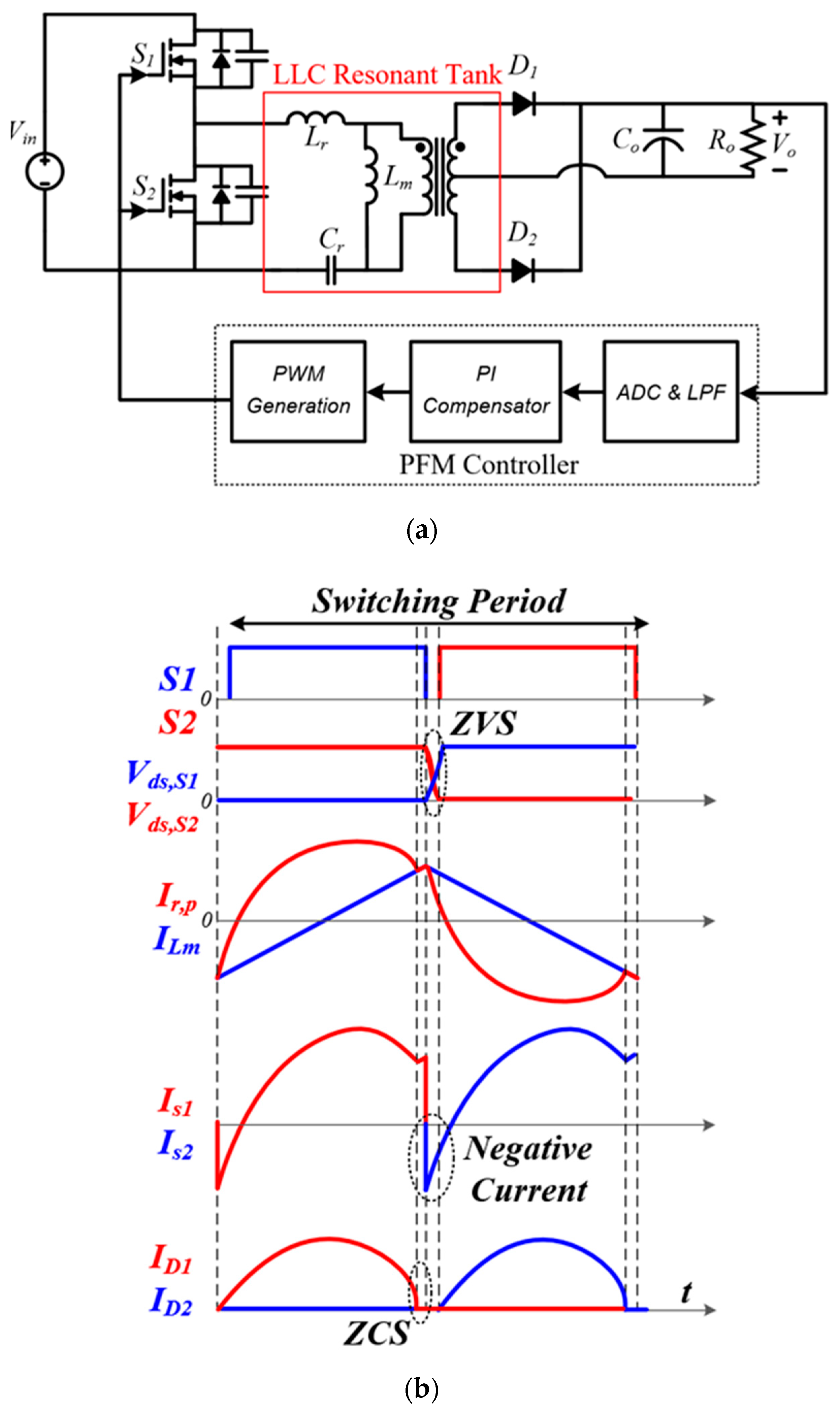
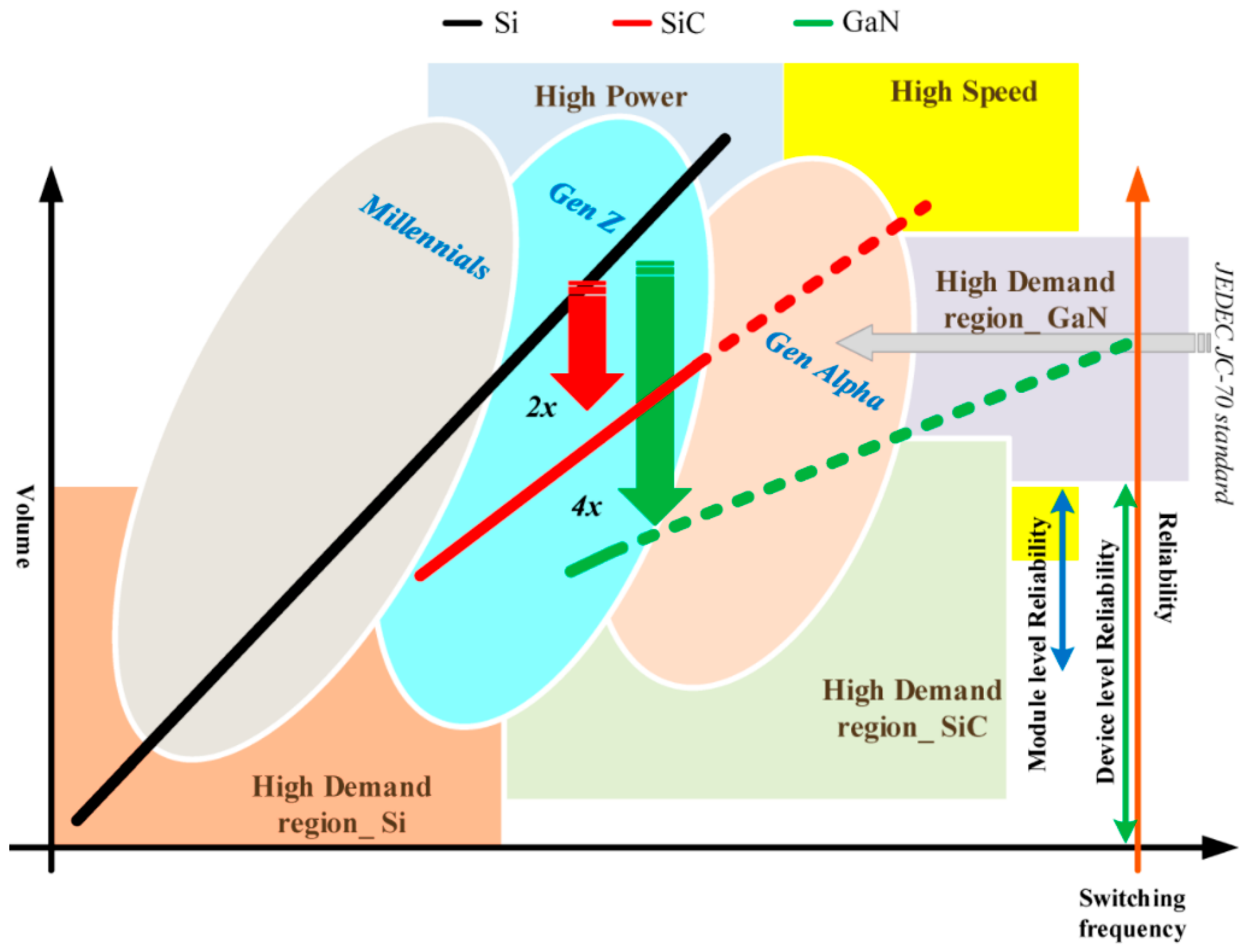
The power converter using a resonance can obtain zero voltage switching (ZVS) and zero current switching (ZCS) on power switches, which can drastically reduce switching losses compared with conventional hard switching converters. In the previous research, various resonant networks have been introduced to utilize the resonance for soft switching characteristics such as L-C series, L-C parallel, LLC, LCL, CLL, CLLC, etc. [1,2,3,4,5,6,7]. Among the resonant networks, the LLC resonant tank has the ZVS capability on the primary side switches, the ZCS capability on the secondary side rectifier, and the small circulating current passing through the transformer [8,9,10]. Figure 1 shows the scheme of the LLC resonant tank and the theoretically operational waveforms of the ZVS and ZCS. The LLC resonant converter has three operational areas. In the below resonant frequency, the primary side switches can obtain the ZVS operation, and the secondary rectifier can obtain the ZCS operation with the proper magnetizing inductance. This area uses the high voltage gain during the middle to the rated load range. In the resonant frequency, the primary switches can obtain the ZVS operation, and the secondary rectifier operates at the borderline of the ZCS operation. This operating area can minimize the circulating current in the converter. At the above resonant frequency, the primary switches can obtain the ZVS operation; however, the secondary rectifier cannot obtain the soft commutation. This area is widely used in the light load and the soft-start duration. Therefore, the LLC resonant converter has been widely used in various industrial fields such as renewable energy, home appliances, and servers in data centers [11,12,13,14,15]. In addition, the LLC resonant converter is good to obtain high switching frequency operations because it has small switching losses using the ZVS and ZCS capabilities. Moreover, the development of wide bandgap (WBG) devices can implement fast switching frequency operations with high power conversion efficiency using small on-resistance, small output capacitance, and extremely low reverse conduction loss [16,17,18,19]. The high switching frequency operation can reduce the size of passive components such as transformers, inductors, and output capacitors, which can improve the power density of the power converter. Figure 2 shows the size reduction of power density improvement according to the switching frequency increment. The high-power density of the power converter results in minimizing the size of the electrical and electronic products.
This paper discusses control algorithms for the high switching frequency LLC resonant converter, which handles power conversion efficiency, output voltage regulation and dynamics, and electro-magnetic interference (EMI). In terms of the power conversion efficiency, the high switching frequency operation induces high switching loss. Especially, the LLC resonant converter has a very high switching frequency operation at the light load condition, which makes poor power conversion efficiency as the increment of the switching frequency. The control algorithms for light load conditions are necessary to improve the power conversion efficiency. In addition, the LLC resonant converter operating at near its series resonant frequency can obtain the minimum circulating current with the ZVS on the primary switches and the ZCS on the secondary rectifiers. The control algorithms for tracking the precise series resonant frequency can obtain the high-power conversion efficiency for the entire load condition. In addition, the conventional diode rectifier has high conduction loss by the forward-biased voltage drop and the reverse conduction. The synchronous rectification algorithms can relieve the power loss on the secondary side rectifier with small conduction loss caused by small on-resistance and almost zero reverse conduction in the WBG devices. This paper is configured with three sections. First, the control algorithms to improve the power conversion efficiency are introduced. Second, the control algorithms for tight output voltage regulation and fast dynamic performance are introduced. Third, the EM noise reduction technique is introduced using the control algorithms which can enhance the voltage regulation performance and the power conversion efficiency of the high-frequency LLC resonant converter.
In terms of the output voltage regulation, the conventional digital signal processors (DSP) have limited computation performance to implement the high switching frequency operation with closed-loop control algorithms. The optimization of programming codes in the controller can alleviate the computation burden. However, the limited pulse frequency modulation (PFM) resolution of the DSP induces the output voltage fluctuation at the high switching frequency operation. The control algorithm is required to regulate the output voltage with the limited PFM resolution.
In terms of the dynamic performance, the high switching frequency operation increases the crossover frequency of the loop gain of the LLC resonant converter. However, the controller has the limited computation performance, so the proper design methodology of the controller is necessary to guarantee both stability and fast dynamic performance of the extremely high switching-frequency LLC resonant converter. Several control algorithms for the high switching frequency LLC resonant converter have been introduced to achieve the fast-dynamic performance and the stable operation using the DSP controllers and field-programmable gate array (FPGA) controllers.
In terms of the EMI, the power converter must satisfy the EMI standard to release the electrical and electronic products for industrial and consumer markets. However, the input EMI filter induces poor cost-effectiveness and low power density in the viewpoint of power conversion systems. Moreover, the high switching frequency operation (several mega-hertz) can generate more conducted emission (CE) noises compared with the conventional switching frequency range (several tens to hundreds of kilohertz). Therefore, the control algorithms for reducing the EMI is necessary to improve the power density and the cost-effectiveness of the power converter.
In this paper, the control algorithms for the high switching-frequency LLC resonant converter are discussed to improve the performance in the power conversion efficiency, the output voltage regulation, and the EMI reduction. In Section 1, several control and modulation methods are explained to improve the power conversion efficiency for the high switching-frequency LLC resonant converter. In Section 2, the control algorithms for the output voltage regulation and the dynamic performance are discussed to guarantee the stability of the high switching-frequency operation and the fast transient-response. In Section 3, the control algorithms are considered to mitigate the CE noises which results in the size reduction of the input EMI filter. All the control algorithms are briefly explained with their operational principles. Lastly, future research issues will be discussed.
2. Control Algorithms for High Efficiency
2.1. Efficiency Improvement at Light Load
Several applications such as home appliances, data centers, and personal computers frequently require light load operations. At the light load condition, the LLC resonant converter needs to operate in high switching frequency using only PFM, which induces large switching loss according to the switching frequency increment. The LLC resonant converter requires the circulating current on the primary side to obtain the ZVS capability, which can reduce the switching loss for entire load ranges. However, this circulating current can induce high conduction loss at the light load condition. Therefore, the improvement in the power conversion efficiency is important at the light load condition.
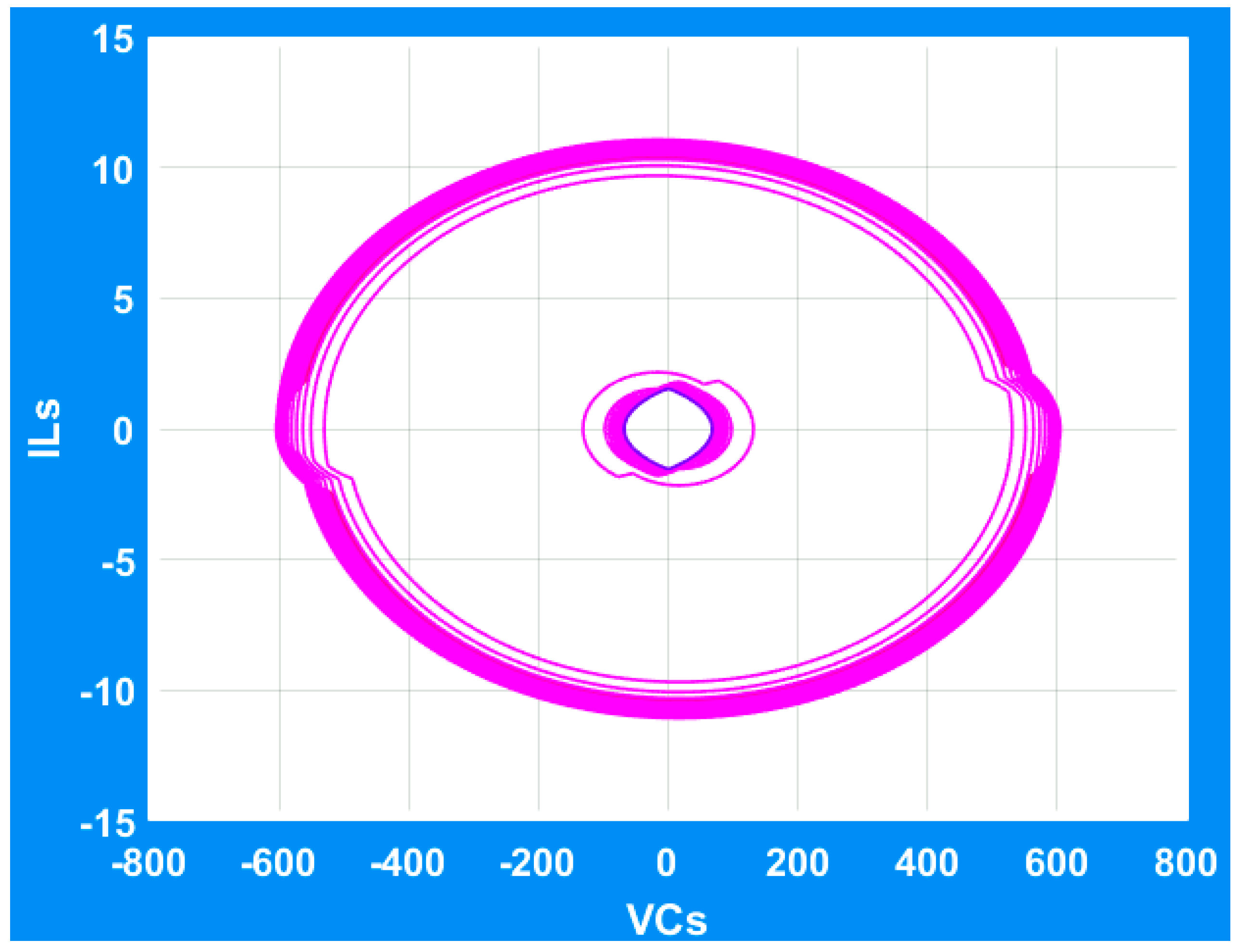
The burst mode operation has widely been used to improve the power conversion efficiency at the light load condition. It can reduce the output voltage regulation performance; however, the impact of the burst mode is very significant at the light load condition with a small number of switching using the dimming signal. In [21], the burst mode operation for the light load condition is introduced with the optimal trajectory based on the state-space analysis. Figure 3 shows the state plane of the LLC resonant converter based on the state space analysis, which can describe the operation of the LLC resonant converter according to the operating modes in the time domain where ILs is the resonant current and VCs is the voltage across the resonant capacitor. The large circle shows the maximum input voltage and the rated load condition. The small circle presents the minimum input voltage and the light load condition. From the state plane, the optimal trajectory can be designed to obtain the switching frequency for the burst mode operation. This optimal switching frequency can maximize the power conversion efficiency; however, it cannot consider the dynamic response of the LLC resonant converter during the burst mode, which can induce the current fluctuation. In [22], the optimal trajectory is also used to implement the burst mode operation. It considers the dynamic operation for the burst mode condition, which can reduce the current fluctuation shown in [21]. The decrement of the current fluctuation reduces the conduction loss compared with [21], which can improve the power conversion efficiency at the light load condition. In [23], the simplified optimal trajectory was introduced by considering the computation speed of a digital controller. The practical burst mode considering the dynamic characteristics of the LLC resonant converter and the digital controller’s interrupt speed can be obtained by a new optimal trajectory compared with [21] and [22].
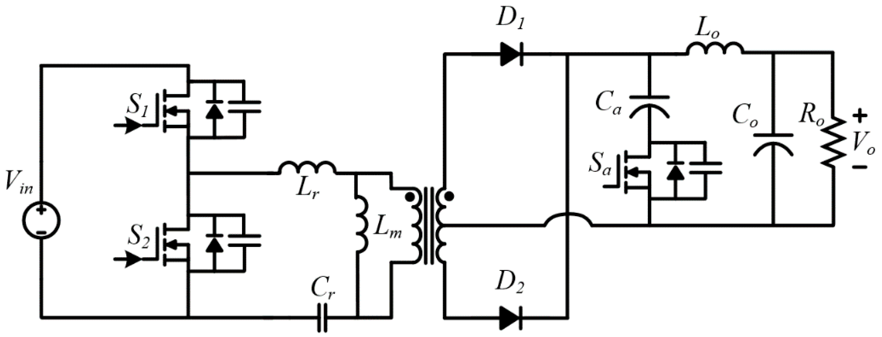
In [24], the combination of an additional switch and capacitor was used to improve the power conversion efficiency and the hold-up time. Figure 4 shows the circuit diagram of the LLC resonant converter with the combination of the switch and capacitor. The modulation of the additional switch minimizes the conduction loss according to the load condition. In addition, the switching frequency decrement at the light load condition can reduce the switching losses. In [25], the pulse-width modulation (PWM) was used at the light load condition to obtain the ZCS operation on the secondary side rectifier. The PFM operates from the middle to the rated load condition. The PFM and PWM hybrid control algorithm can also be used at the light load condition. This method can guarantee the ZCS operation on the secondary side rectifier for the entire load condition. However, it has high conduction loss on the primary side switches and their anti-parallel diode with the circulating current. In addition, the duty variation is very limited to guarantee the ZVS operation.
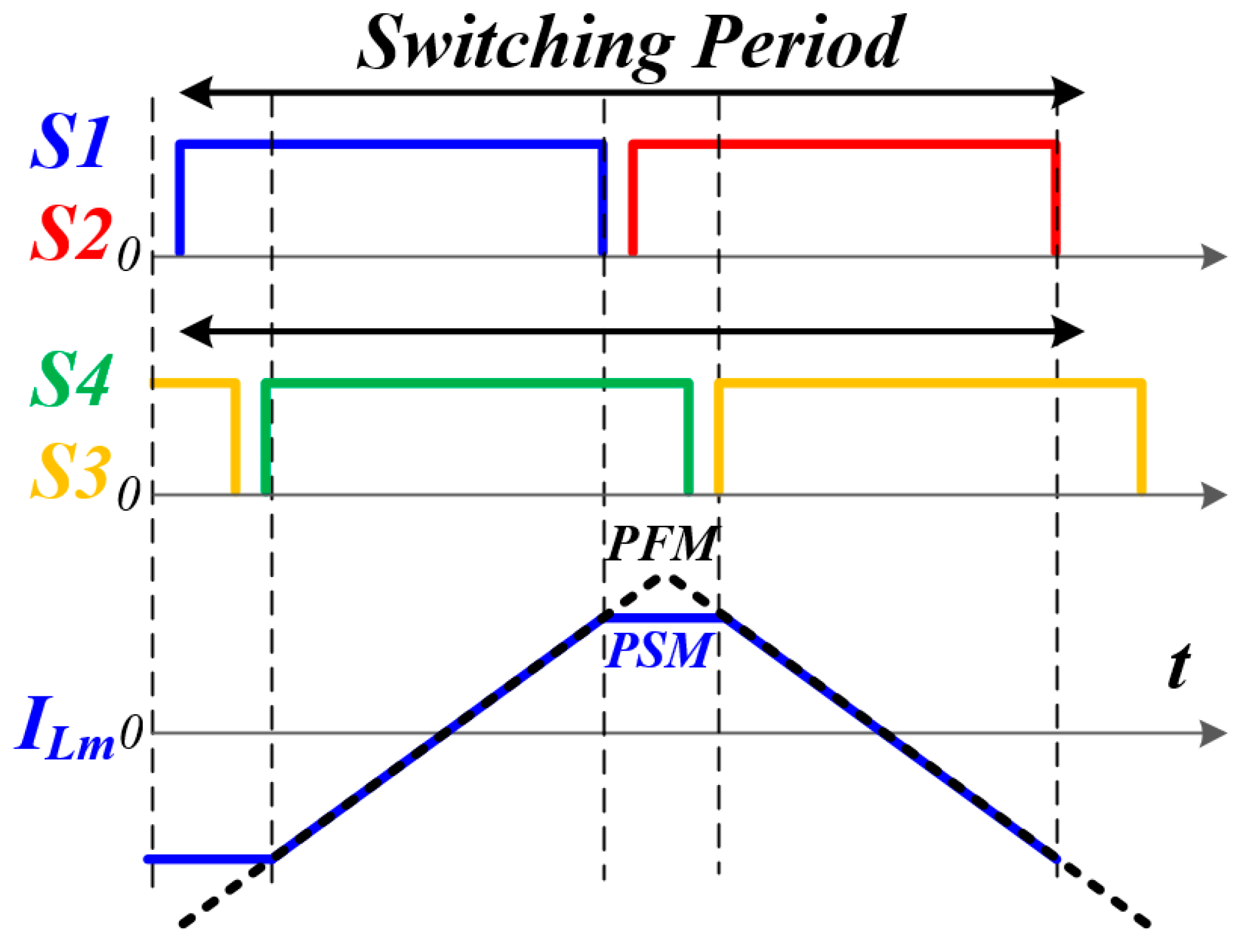
In [26], a phase shift modulation (PSM) was used to reduce the circulating current at the light load condition. The phase shift operation between the primary switch legs can reduce the circulating current on the primary side. Figure 5 shows the operational principles of the circulating current reduction using the PSM. The phase shift ratio between the switch legs can be determined with the load condition to obtain the ZVS operation on the primary switches. However, this method can be applied to only the full-bridge structure. In [27], the PFM, PWM, and burst mode operation were used according to the load condition. The burst mode and the PWM operate at the light and the middle load conditions, respectively. The algorithm can obtain the soft-switching capability for the entire load condition. In [28], the synchronous rectification method was introduced to improve the output voltage regulation performance at the light load condition. In addition, the power conversion efficiency at the light load condition is improved by the reduction of the switching frequency variation, which mitigates the switching loss. This method uses only the duty modulation of the secondary side rectifier to regulate the output voltage.
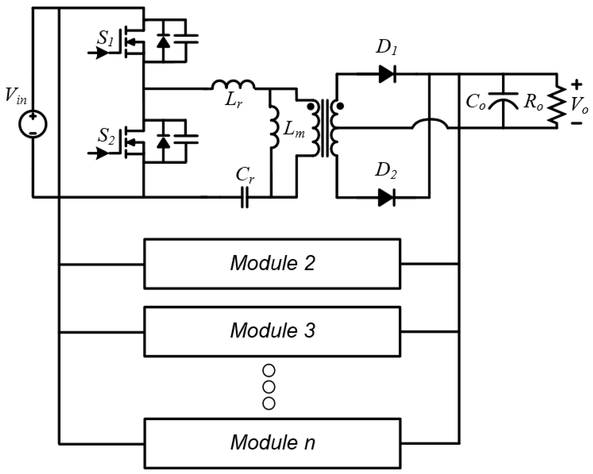
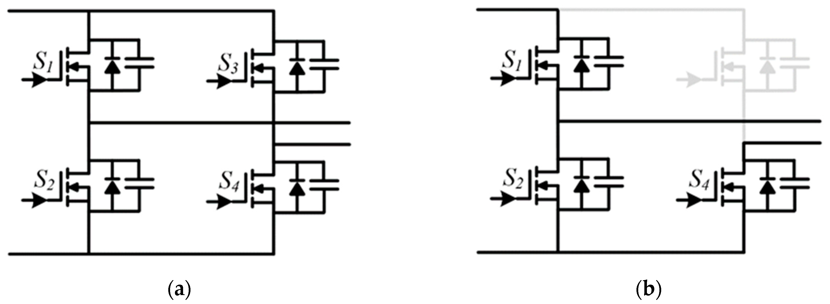
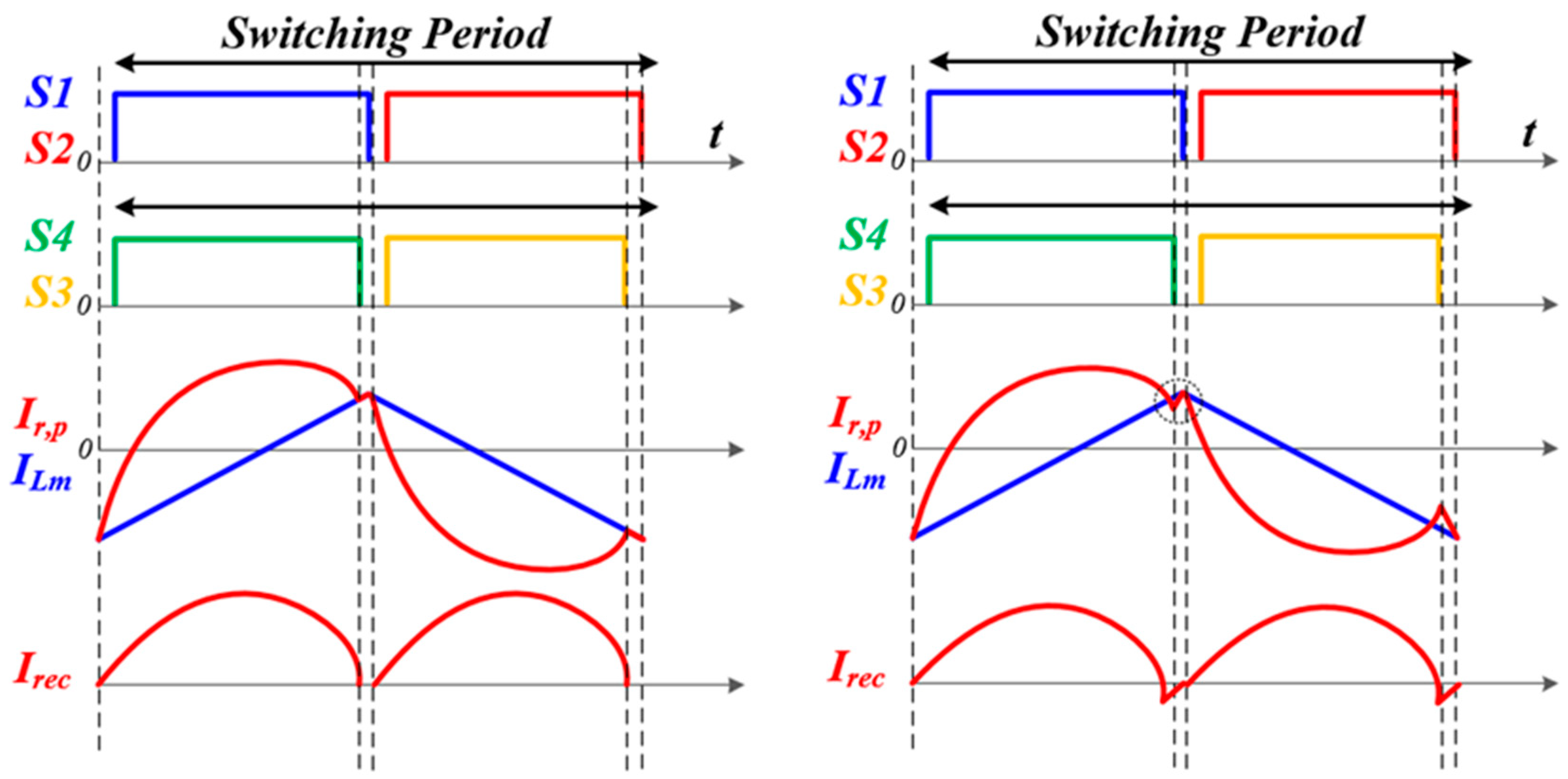
In [29], the light load efficiency improvement of a modular type LLC resonant converter was introduced with an on/off control method. Figure 6 shows the circuit diagram of parallel connected modular type converters. The modular converter selectively operates according to the load conditions. Therefore, the optimization of efficiency maximized point tracking is required for this control algorithm. In [30], the operating mode change between the full-bridge and the half-bridge was introduced to maximize the power conversion efficiency at the light load condition. Figure 7 shows the full and half-bridge modulations. The half-bridge modulation operates at the light load condition. The full-bridge modulation operates at the middle to rated load conditions.
2.2. Resonant Frequency Tracking
The switching frequency over the series resonant frequency cannot obtain the ZCS capability on the secondary side rectifier, which increases the switching loss. The switching frequency below the series resonant frequency has a large circulating current, which increases the conduction loss on the primary side. The switching frequency operating at the series resonant frequency can minimize the circulating current with the ZCS condition on the secondary side rectifier, which can obtain the maximum power conversion efficiency. Therefore, the series resonant frequency tracking technique has been introduced to obtain the maximum power conversion efficiency.
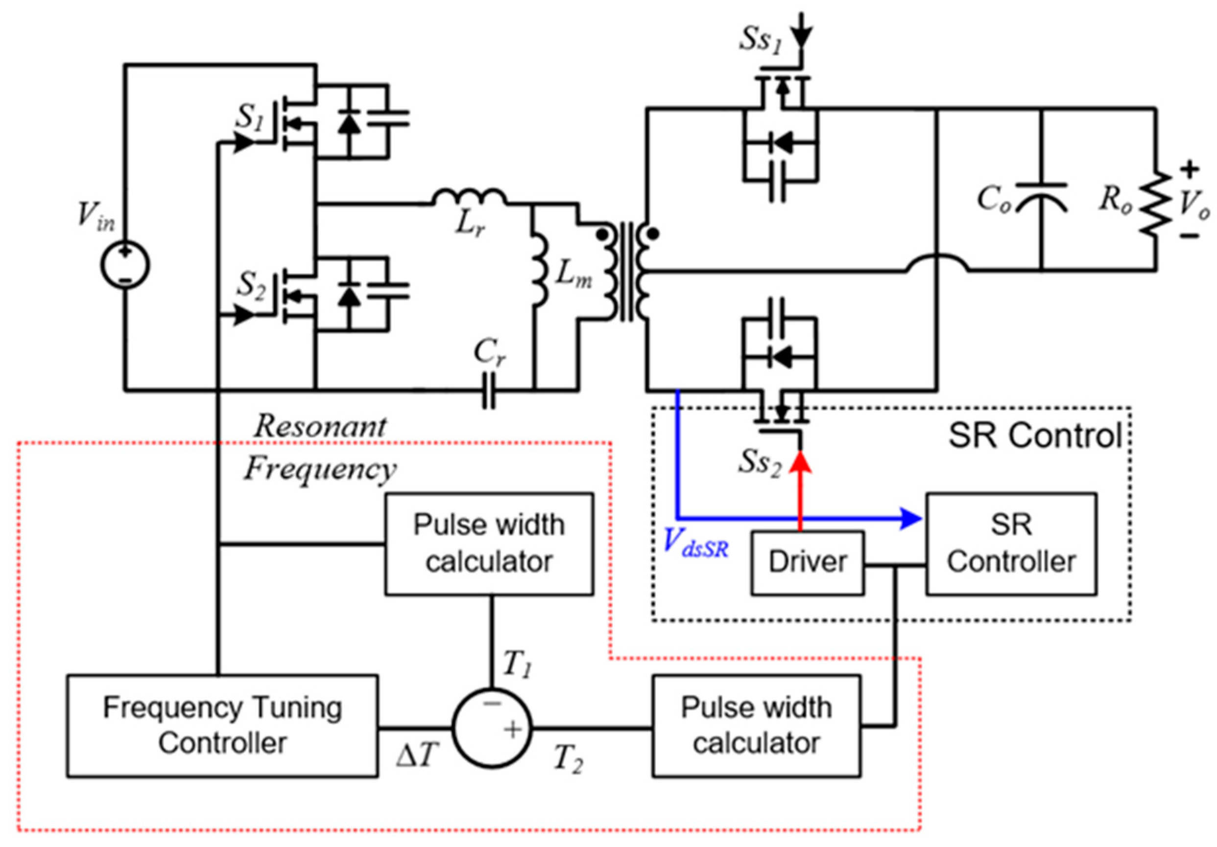
In [31], the drain-source voltage of a synchronous rectifier is used to achieve the resonant frequency tracking. The threshold value and the reverse-biased drain-source voltage determines the switching frequency to track the resonant frequency. Figure 8 shows the circuit diagram of the resonant frequency tracking method using the synchronous rectification.
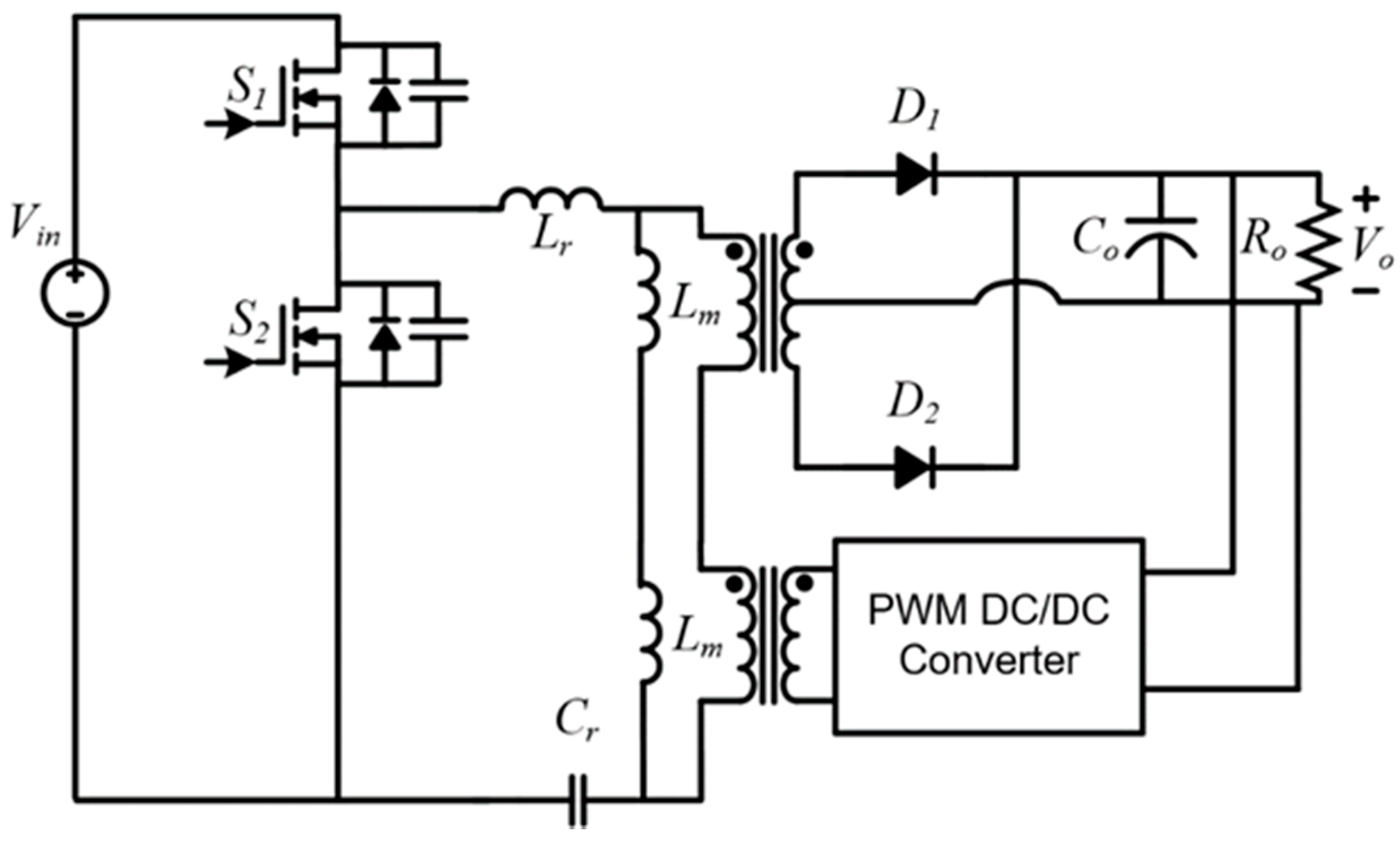
The comparison of the duty ratio between the primary switch and the synchronous rectifier can detect the resonant frequency. In [32], the zero current duration is measured to detect the resonant frequency. This method is good to regulate the resonant frequency using the diode rectifier. The operational principle is similar to the method presented in [30]. However, it requires additional current sensors to detect the resonant frequency. In [33,34,35], and [36], the resonant frequency can be detected by the voltage gain analysis, which considers the non-ideality of the voltage gain. The theoretical analysis can determine the resonant frequency. The switching frequency tracks the series resonant frequency. The phase shift modulation (PSM) regulates the output voltage. In [37], the LLC resonant converter operating at the resonant frequency was introduced with the output voltage regulation using the secondary side DC-DC converter. Figure 9 shows the scheme of the DC transformer with the output voltage regulation capability.
The resonant frequency operation can maximize the power conversion efficiency. The secondary side additional converter can regulate the output voltage. All the results show that the resonant frequency tracking techniques can improve the power conversion efficiency compared with the conventional PFM.
2.3. Secondary Side Synchronous Rectification
The conventional diode rectifier has large conduction loss caused by the threshold voltage of the rectifiers and the reverse conduction of the power switches. As the switching frequency increment, the reverse conduction loss is proportionally increased. The synchronous rectifier based on the gallium nitride (GaN) power switches can mitigate the conduction loss using small on-resistance and no reverse conduction. Therefore, the synchronous rectification is important to obtain high power conversion efficiency at the high switching frequency operation.
In [38], the drain-source voltage is used to calculate the duty cycle of the synchronous rectifier. Figure 10 shows the operational principle of the synchronous rectification method shown in [38]. It can overcome the effect of parasitic inductance.
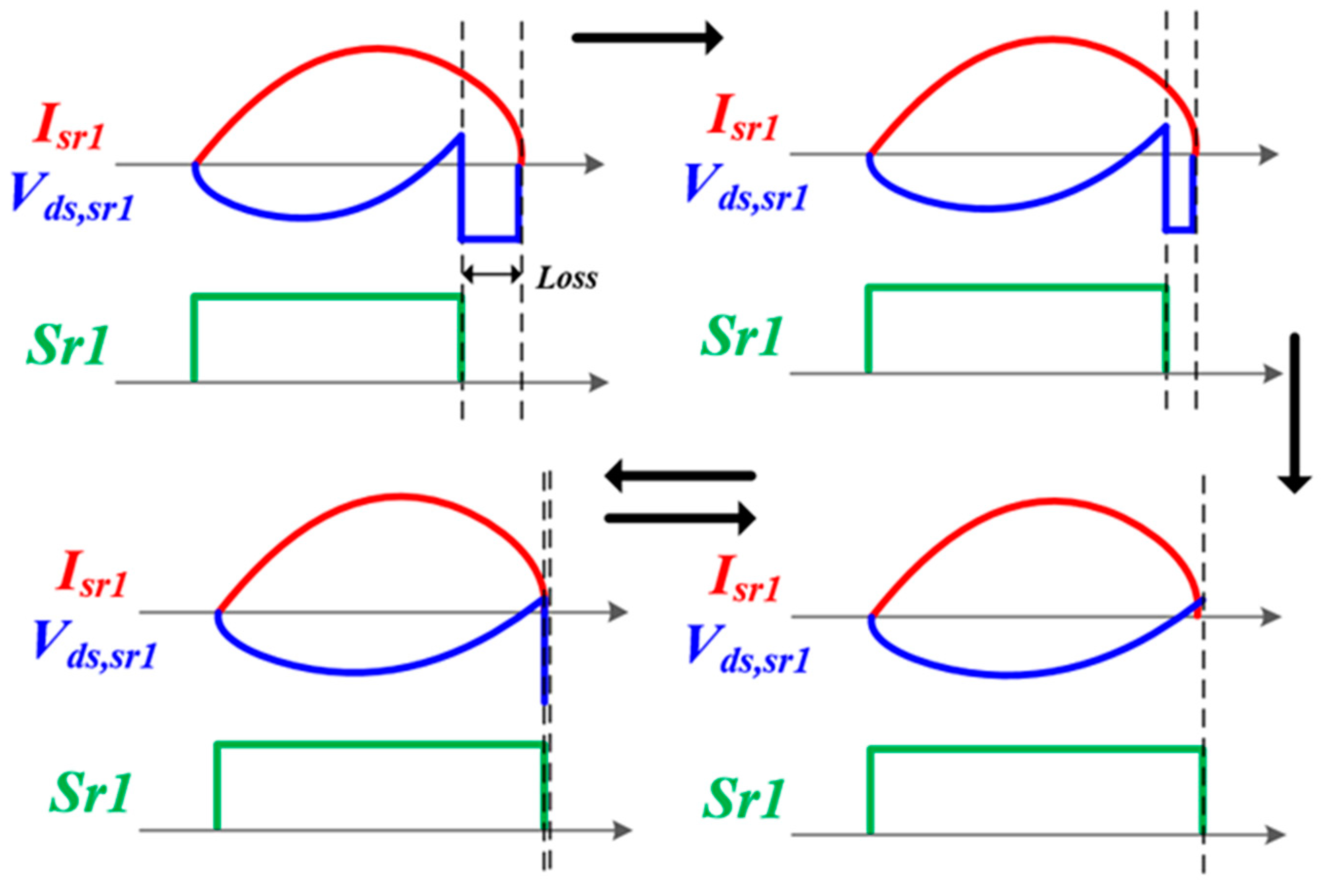
In [39], the drain-source voltage sensing method is improved by the considerations of the computation performance of a digital signal processor (DSP). It discussed the practical computation burden to determine the turn-on duration of the synchronous rectifier. In [28], the turn-on time modulation for the synchronous rectifier was introduced to improve the light load efficiency. Figure 11 shows the modulation method shown in [28].
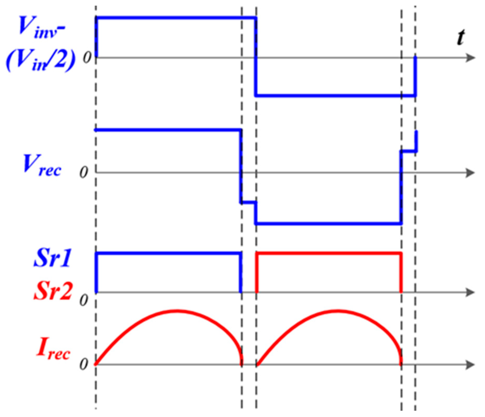
The extended turn-on time modulation at the light load condition can obtain the tight output voltage regulation with lower switching frequency compared with the conventional PFM. In [40], the zero-crossing noise filter was introduced to overcome noise issues on the secondary side current sensing method. The RCD filter can eliminate the secondary side current noise. The RC design is important to obtain appropriate operation. In [41], the input voltage, the output voltage, and the voltage across the resonant capacitor are used to obtain the turn-on duration. It shows the relationship analysis among those voltage values, which can overcome the noise issue. In [42], the input voltage, the inverting voltage, and the secondary side voltage of the transformer are measured to generate the gate signal for the synchronous rectifier. Figure 12 shows the modulation algorithm shown in [42].
The measured voltages are not sensitive compared with the previous method, which has high noise immunity.
3. Control Algorithms for Voltage Regulation and Dynamic Performance
3.1. Output Voltage Regulation
The LLC resonant converter operating at high switching frequency requires high PFM resolution to tightly regulate the output voltage. However, the high switching frequency operation induces a limited PFM resolution of the digital signal processor (DSP) because of its limited computation performance. In [43], the PFM and PWM hybrid control algorithm was introduced to overcome the limited PFM resolution of the DSP. Figure 13 shows the theoretical output voltage waveforms regulated by the hybrid control algorithm.
The PFM determines the operating point and the PWM regulates the output voltage, which can improve the output voltage regulation performance compared with the conventional PFM.
3.2. Fast Dynamic Performance
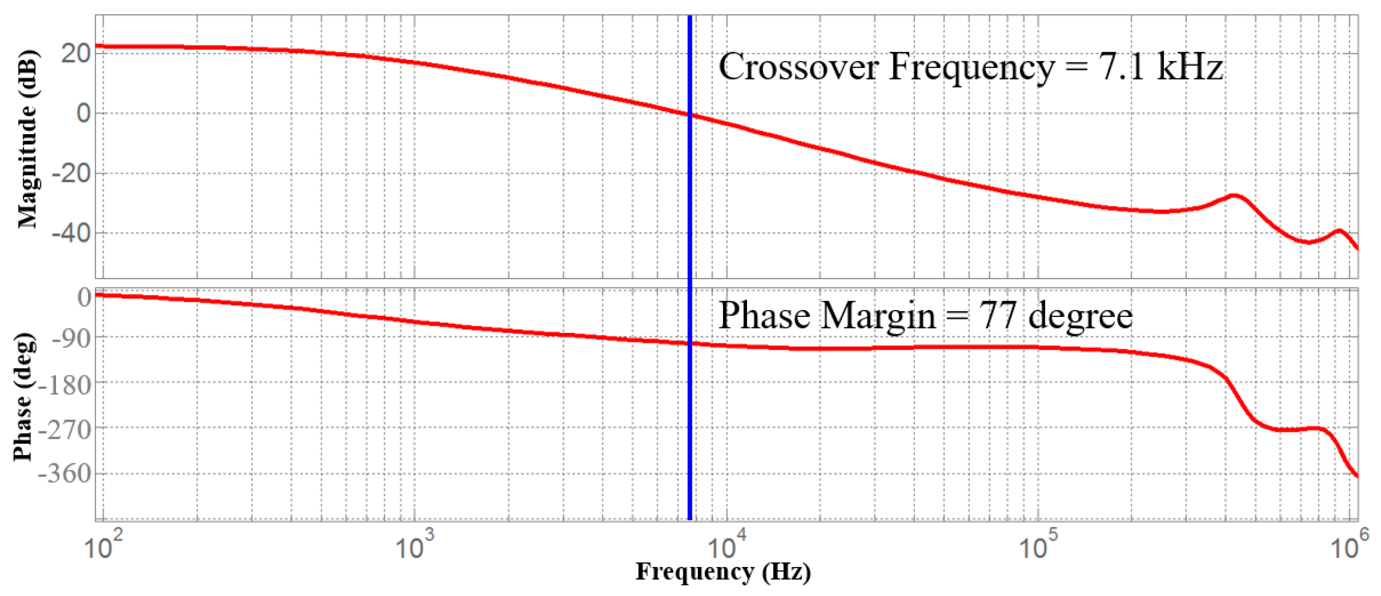
The fast switching frequency of the LLC resonant converter can obtain high crossover frequency with enough phase margin at the closed loop condition. However, the feedback controller has limited computation performance, which can degrade the dynamic performance of the power converter. In [44] and [45], the soft-start algorithm was introduced to obtain the fast response of the LLC resonant converter. The non-linear type controller was designed by the large-signal model of the LLC converter, which follows the optimal trajectory of a state plane. This method has limited inrush current, suppressed output voltage overshoot, and fast dynamic performance during the soft-start duration. In [46], the non-linear observer-based controller was designed to obtain good stability and fast dynamic performance. The non-linear model is derived by the extended describing functions (EDFs). Figure 14 shows the Bode plot of the LLC resonant converter using its small signal model derived by the EDFs [47,48]. The small signal analysis can be described as Equations (1)–(5):
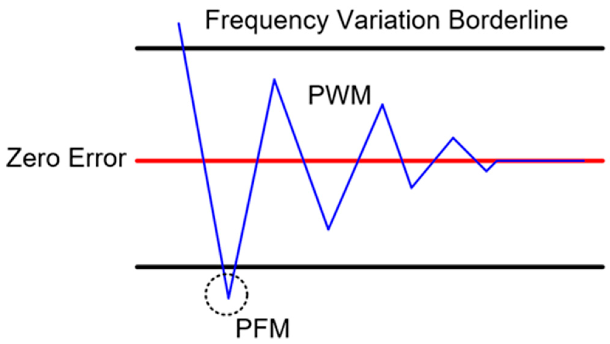
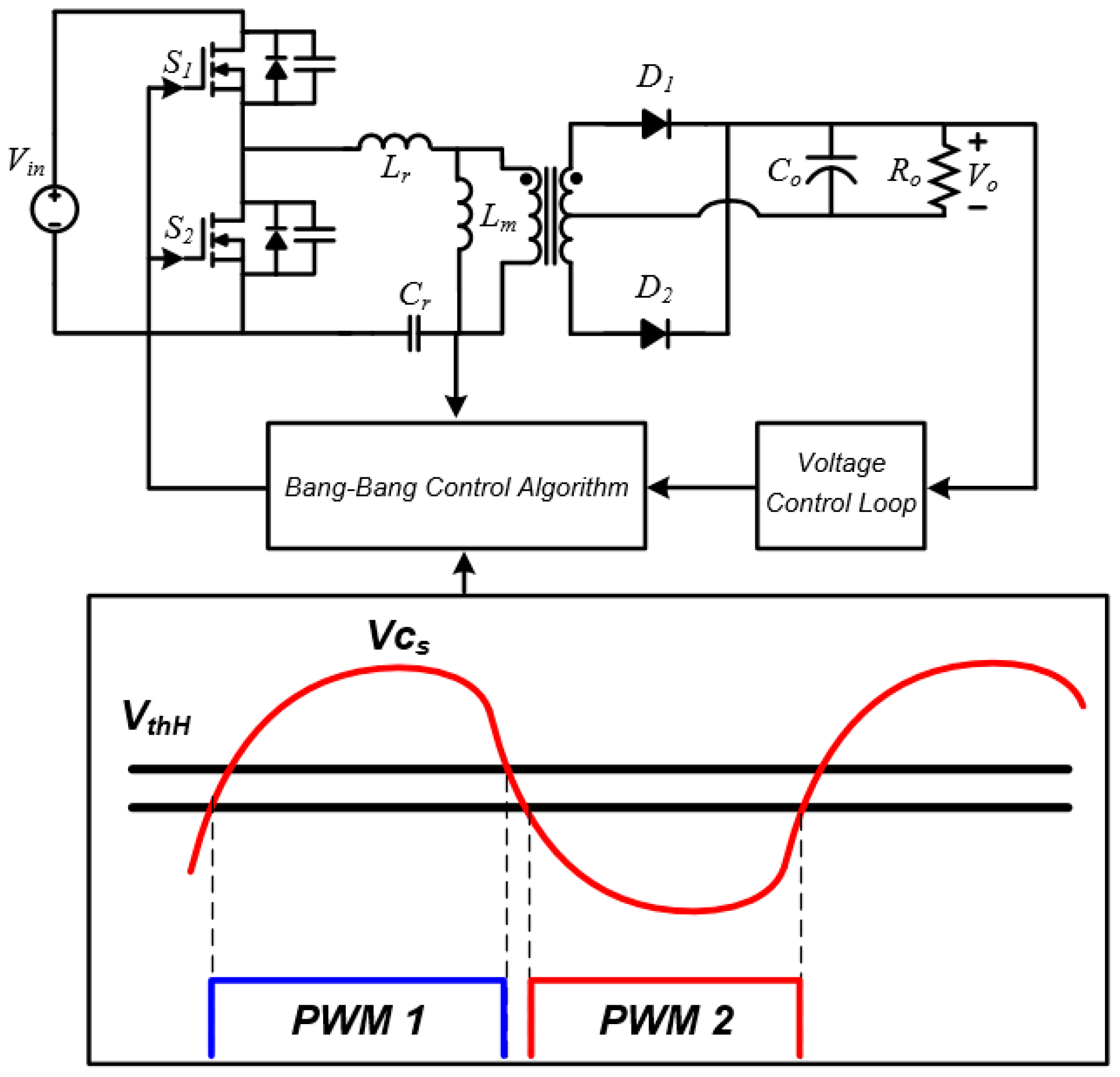
The small-signal model using the observer can increase the crossover frequency with enough phase margin compared with the conventional PID controller, which can improve the dynamic performance during the transient operation. In [49], the voltage-controlled oscillator was used to obtain the high dynamics performance under the high frequency operation of the LLC resonant converter. In addition, the modern control theory was used to obtain the fast-dynamic performance in [50]. A bang-bang charge control algorithm uses voltage level across the resonant capacitor and its threshold values. Figure 15 shows the operational waveforms of the bang-bang charge control algorithm. The stability of the high frequency LLC resonant converter was analyzed with the small-signal modeling.
4. Control Algorithm for EMI Reduction
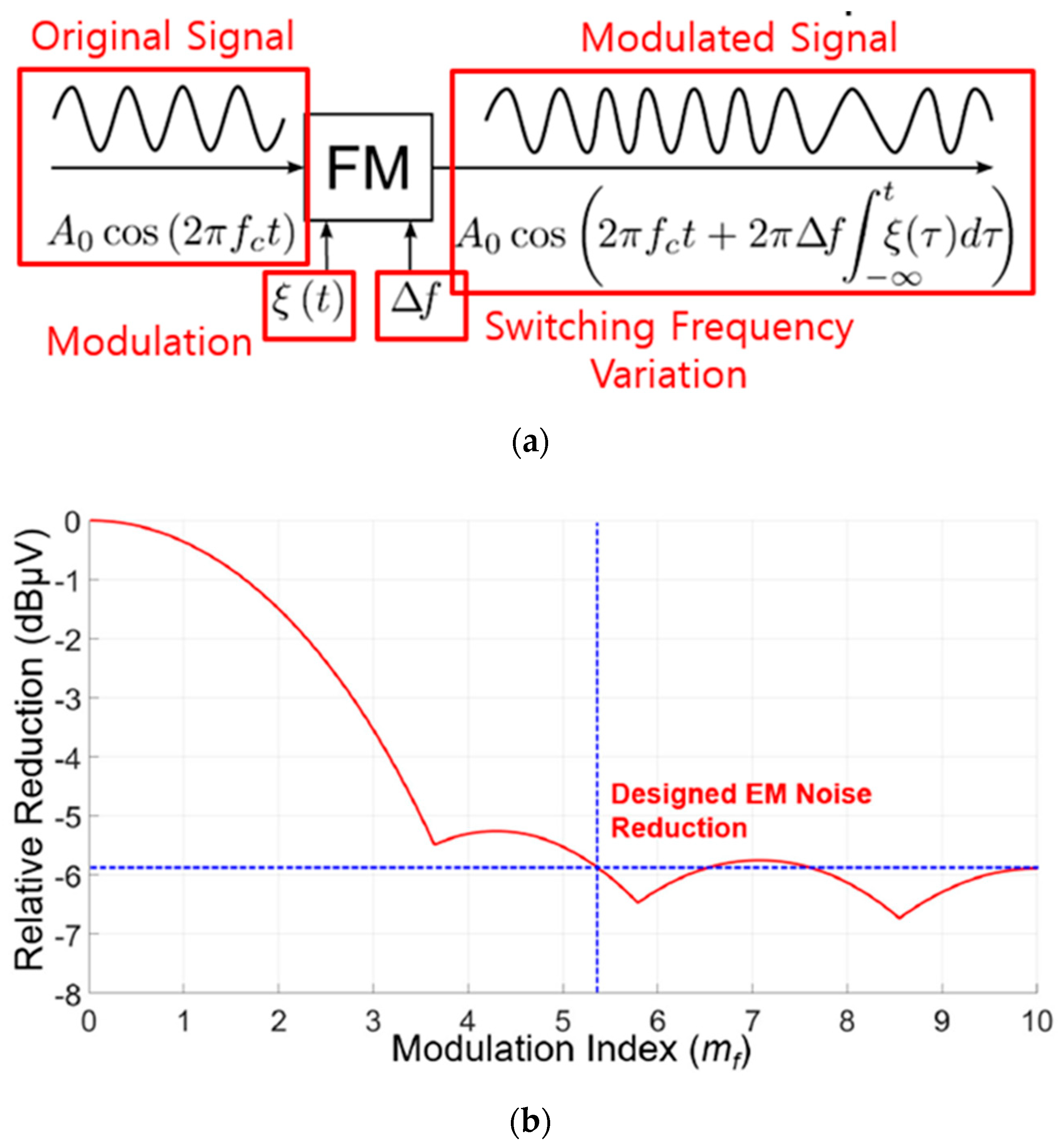
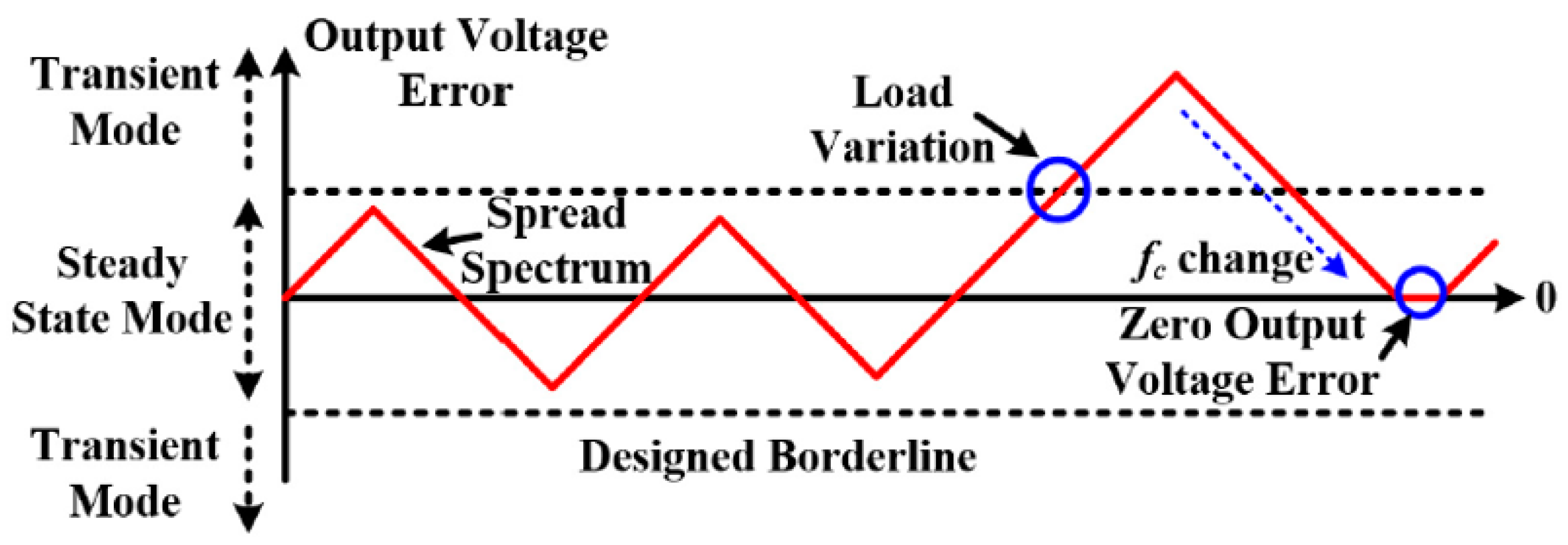
The high switching frequency operation of the LLC resonant converters has to consider the conducted emission (CE) noise standard near the switching frequency. Therefore, the EM noise suppression is important to satisfy the EMI standard and to obtain high-power density with a small EMI filter. In terms of the control algorithm, the spread spectrum technique (SST) can reduce the CE noise of power converters effectively. Figure 16a shows the operational principle of the SST. The switching frequency is modulated according to predetermined switching patterns, which can be designed to effectively suppress the EM noise of the power converter. The wide switching frequency variation and slow modulation frequency are effective to reduce the EM noise. However, the wide switching frequency variation can induce large output voltage fluctuation by input-output voltage gain variation according to the switching frequency in the resonant converter. The modulation frequency is designed by the resolution of the bandwidth (RBW) of EM noise measurement. The modulation index can be described as mf (mf =∆f/fm, where ∆f is the frequency deviation and fm is the frequency of the modulating waveform). The large mf is effective to reduce the EM noise. However, it can induce poor output voltage regulation performance in the LLC resonant converter.
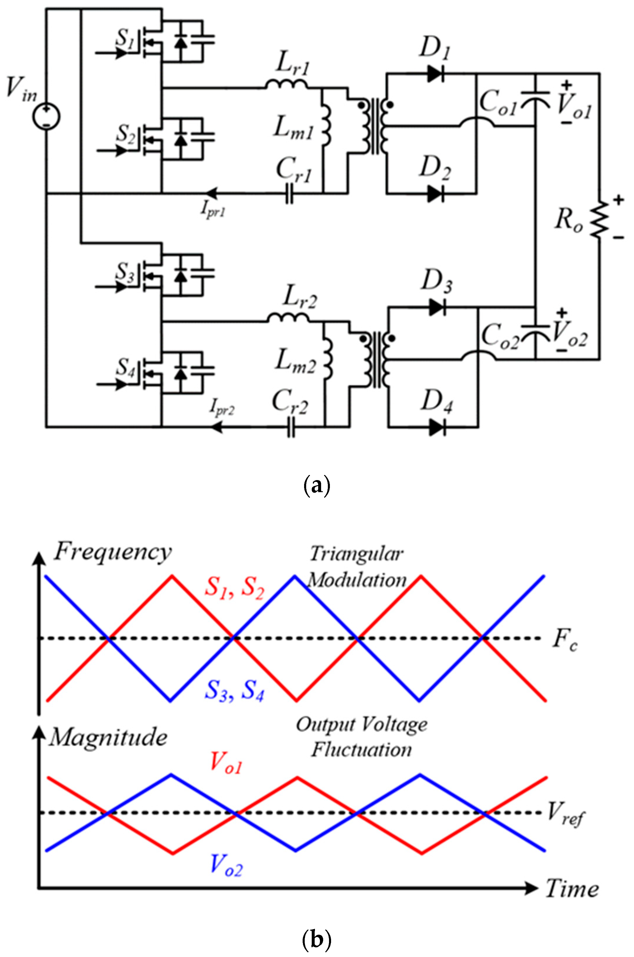
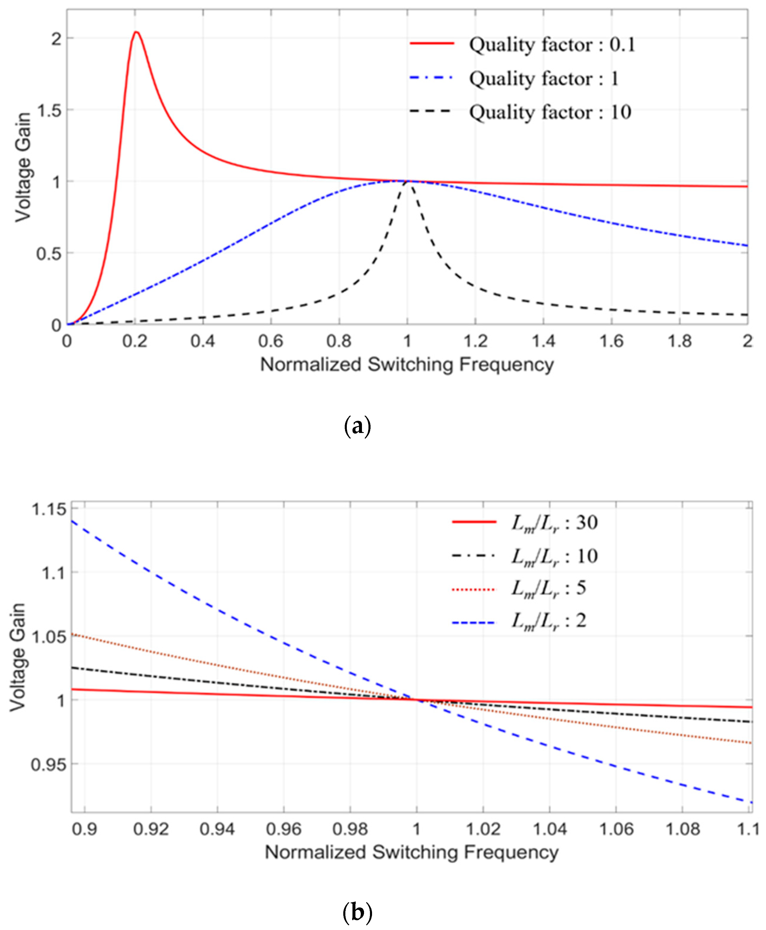
In [51], the PFM and PSM hybrid control algorithm was introduced to tightly regulate the output voltage under the SST. The PFM determines the DC operating point. The PSM regulates the output voltage under the SST. Figure 17 shows the hybrid control algorithm. It can effectively reduce the CE noise. However, the spread spectrum cannot operate during the transient state. In [52], the parallel-series type LLC resonant converter can use the spread spectrum modulation for the output voltage regulation. Figure 18a shows the scheme of the parallel-series LLC resonant converter. The phase shift algorithm between the parallel connected LLC resonant converter can tightly regulate the output voltage under wide switching frequency variation. Figure 18b shows the control algorithm of [52]. The phase shift algorithm can reduce the EM noise and the output voltage fluctuation. However, it cannot be applied to the conventional LLC resonant converter. In [53], the asymmetric pulse width modulation (APWM) is used to regulate the output voltage under the SST. The quality factor design can obtain the flat voltage gain according to the switching frequency. Figure 19 shows the flat voltage gain according to the quality factor design. The duty variation of the APWM can regulate the output voltage under the spread spectrum modulation, which can reduce two-stage EMI filters to a single-stage EMI filter.
5. Conclusion
The LLC resonant converter with the high switching frequency operation has been developed to obtain high power density with high power conversion efficiency. In this paper, the overview of the control algorithms is introduced to improve the performance of the high frequency LLC resonant converter. Several control algorithms have been used in terms of power conversion efficiency, tight output voltage regulation, dynamic performance, and EM noise reduction. The operational principles of each control algorithms are briefly explained to review their operational characteristics. The performance of the high frequency LLC resonant converter has been improved using the state-of-art active and passive components, hardware design, and the controllers. Specifically, the advanced controllers, such as DSPs and FPGAs, can provide high computation performance so that it can improve the performance as well as the control flexibility of the high frequency LLC resonant converter. For further developments, the modern control algorithms with high computation burden can be used to control the LLC resonant converter aiming to enhance dynamic performance and power conversion efficiency. Besides, the active EMI reduction method for the high frequency LLC resonant converter can be integrated into the control algorithms so that it can obtain low EMI noise emission, tight output voltage regulation, and high controllability with superior computation performance of the controller.
Author Contributions
Conceptualization, H.-P.P. and M.K.; methodology, H.-P.P.; software, H.-P.P.; validation, H.-P.P., M.K., and J.-H.J.; formal analysis, H.-P.P.; investigation, H.-P.P.; resources, M.K.; data curation, H.-P.P.; writing—original draft preparation, H.-P.P.; writing—review and editing, J.-H.J.; visualization, H.-P.P.; supervision, J.-H.J.; project administration, J.-H.J.; funding acquisition, J.-H.J. All authors have read and agreed to the published version of the manuscript.
Funding
This work was supported by Korea Electric Power Corporation (R18XA06-72). This work was conducted under framework of the research and development program of the Korea institute of energy research (C0-2411).
Conflicts of Interest
The authors declare no conflict of interest.
References
- Hou, J.; Chen, Q.; Ren, X.; Ruan, X.; Wong, S.; Tse, C.K. Precise characteristics analysis of series/series-parallel compensated contactless resonant converter. IEEE J. Emerg. Sel. Top. Power Electron. 2015, 3, 101–110. [Google Scholar]
- Bonache-Samaniego, R.; Olalla, C.; Martínez-Salamero, L. Dynamic modeling and control of self-oscillating parallel resonant converters based on a variable structure systems approach. IEEE Trans. Power Electron. 2017, 32, 1469–1480. [Google Scholar] [CrossRef]
- Mao, M.; Tchobanov, D.; Li, D.; Maerz, M. Design optimisation of a 1 MHz half-bridge CLL resonant converter. IET Power Electron. 2008, 1, 100–108. [Google Scholar] [CrossRef]
- Borage, M.; Tiwari, S.; Kotaiah, S. LCL-T resonant converter with clamp diodes: A novel constant-current power supply with inherent constant-voltage limit. IEEE Trans. Ind. Electron. 2007, 54, 741–746. [Google Scholar] [CrossRef]
- Liu, Y.; Du, G.; Wang, X.; Lei, Y. Analysis and Design of high-efficiency bidirectional gan-based CLLC resonant converter. Energies 2019, 12, 3859. [Google Scholar] [CrossRef] [Green Version]
- Lin, B.-R. Implementation of a parallel-series resonant converter with wide input voltage range. Energies 2019, 12, 4095. [Google Scholar] [CrossRef] [Green Version]
- Lin, B.-R. Resonant converter with soft switching and wide voltage operation. Energies 2019, 12, 3479. [Google Scholar] [CrossRef] [Green Version]
- Li, F.; Hao, R.; Lei, H.; Zhang, X.; You, X. The influence of parasitic components on LLC resonant converter. Energies 2019, 12, 4305. [Google Scholar] [CrossRef] [Green Version]
- Lin, Y.-C.; Chen, D.-T.; Chen, C.-J. Flux-balance control for LLC Resonant converters with center-tapped transformers. Energies 2019, 12, 3211. [Google Scholar] [CrossRef] [Green Version]
- Yoon, D.; Lee, S.; Cho, Y. Design considerations of series-connected devices based LLC converter. Energies 2020, 13, 264. [Google Scholar] [CrossRef] [Green Version]
- Kim, E.-S.; Oh, J.-S. High-efficiency bidirectional llc resonant converter with primary auxiliary windings. Energies 2019, 12, 4692. [Google Scholar] [CrossRef] [Green Version]
- Cha, H.-R.; Kim, R.-Y. Voltage balance switching scheme for series-connected SiC MOSFET LLC resonant converter. Energies 2019, 12, 4003. [Google Scholar] [CrossRef] [Green Version]
- Watanabe, H.; Itoh, J.-I.; Koike, N.; Nagai, S. PV micro-inverter topology using LLC resonant converter. Energies 2019, 12, 3106. [Google Scholar] [CrossRef] [Green Version]
- Abdel-Rahim, O.; Alamir, N.; Abdelrahem, M.; Orabi, M.; Kennel, R.; Ismeil, M.A. A phase-shift-modulated LLC-Resonant micro-inverter based on fixed frequency predictive-MPPT. Energies 2020, 13, 1460. [Google Scholar] [CrossRef] [Green Version]
- Yang, J.-W.; Han, S.-K. A Si-FET-based high switching frequency three-level LLC resonant converter. Energies 2019, 12, 3082. [Google Scholar] [CrossRef] [Green Version]
- Gamand, F.; Li, M.D.; Gaquiere, C. A 10-MHz GaN HEMT DC/DC boost converter for power amplifier applications. IEEE Trans. Circuits Syst. II Express Briefs 2012, 59, 776–779. [Google Scholar] [CrossRef]
- Akuzawa, Y.; Ito, Y.; Ezoe, T.; Sakai, K. A 99%-efficiency GaN converter for 6.78 MHz magnetic resonant wireless power transfer system. J. Eng. 2014, 2014, 598–600. [Google Scholar] [CrossRef]
- Hariya, A.; Koga, T.; Matsuura, K.; Yanagi, H.; Tomioka, S.; Ishizuka, Y.; Ninomiya, T. Circuit design techniques for reducing the effects of magnetic flux on GaN-HEMTs in 5-MHz 100-W high power-density LLC resonant DC–DC converters. IEEE Trans. Power Electron. 2017, 32, 5953–5963. [Google Scholar] [CrossRef]
- Zhang, Y.; Rodríguez, M.; Maksimović, D. Very high frequency PWM buck converters using monolithic GaN half-bridge power stages with integrated gate drivers. IEEE Trans. Power Electron. 2016, 31, 7926–7942. [Google Scholar] [CrossRef]
- Chakraborty, S.; Vu, H.-N.; Hasan, M.M.; Tran, D.-D.; Baghdadi, M.E.; Hegazy, O. DC-DC converter topologies for electric vehicles, plug-in hybrid electric vehicles and fast charging stations: State of the art and future trends. Energies 2019, 12, 1569. [Google Scholar] [CrossRef] [Green Version]
- Feng, W.; Lee, F.C.; Mattavelli, P. Optimal trajectory control of burst mode for LLC resonant converter. IEEE Trans. Power Electron. 2013, 28, 457–466. [Google Scholar] [CrossRef]
- Feng, W.; Lee, F.C.; Mattavelli, P. Optimal trajectory control of LLC resonant converters for LED PWM dimming. IEEE Trans. Power Electron. 2014, 29, 979–987. [Google Scholar] [CrossRef]
- Fei, C.; Li, Q.; Lee, F.C. Digital implementation of light-load efficiency improvement for high-frequency LLC converters with simplified optimal trajectory control. IEEE J. Emerg. Sel. Top. Power Electron. 2018, 6, 1850–1859. [Google Scholar] [CrossRef]
- Lee, J.; Kim, J.; Kim, J.; Baek, J.; Moon, G. A high-efficiency PFM Half-bridge converter utilizing a half-bridge LLC converter under light load conditions. IEEE Trans. Power Electron. 2015, 30, 4931–4942. [Google Scholar] [CrossRef]
- Pan, H.; He, C.; Ajmal, F.; Chen, H.; Chen, G. Pulse-width modulation control strategy for high efficiency LLC resonant converter with light load applications. IET Power Electron. 2014, 7, 2887–2894. [Google Scholar] [CrossRef]
- Kim, J.; Kim, C.; Kim, J.; Lee, J.; Moon, G. Analysis on load-adaptive phase-shift control for high efficiency full-bridge LLC Resonant converter under light-load conditions. IEEE Trans. Power Electron. 2016, 31, 4942–4955. [Google Scholar]
- Fang, Z.; Huang, Z.; Jing, H.; Liu, F. Hybrid mode-hopping modulation for LLC resonant converter achieving high efficiency and linear behavior. IET Power Electron. 2020, 13, 1153–1162. [Google Scholar] [CrossRef]
- Kim, K.; Youn, H.; Baek, J.; Jeong, Y.; Moon, G. Analysis on synchronous rectifier control to improve regulation capability of high-frequency LLC resonant converter. IEEE Trans. Power Electron. 2018, 33, 7252–7259. [Google Scholar] [CrossRef]
- Nguyen, H.; Zane, R.; Maksimović, D. ON/OFF control of a modular DC–DC Converter based on active-clamp LLC modules. IEEE Trans. Power Electron. 2015, 30, 3748–3760. [Google Scholar] [CrossRef]
- Fei, C.; Ahmed, M.H.; Lee, F.C.; Li, Q. Two-stage 48 V-12 V/6 V-1.8 V voltage regulator module with dynamic bus voltage control for light-load efficiency improvement. IEEE Trans. Power Electron. 2017, 32, 5628–5636. [Google Scholar] [CrossRef]
- Feng, W.; Mattavelli, P.; Lee, F.C. Pulsewidth locked loop (PWLL) for Automatic resonant frequency tracking in LLC DC–DC transformer (LLC-DCX). IEEE Trans. Power Electron. 2013, 28, 1862–1869. [Google Scholar] [CrossRef]
- Li, H.; Jiang, Z. On automatic resonant frequency tracking in LLC Series resonant converter based on zero-current duration time of secondary diode. IEEE Trans. Power Electron. 2016, 31, 4956–4962. [Google Scholar] [CrossRef]
- Kundu, U.; Chakraborty, S.; Sensarma, P. Automatic resonant frequency tracking in parallel LLC boost DC–DC converter. IEEE Trans. Power Electron. 2015, 30, 3925–3933. [Google Scholar] [CrossRef]
- Kundu, U.; Sensarma, P. Gain-relationship-based automatic resonant frequency tracking in parallel LLC converter. IEEE Trans. Ind. Electron. 2016, 63, 874–883. [Google Scholar] [CrossRef]
- Kundu, U.; Sensarma, P. A unified approach for automatic resonant frequency tracking in LLC DC–DC converter. IEEE Trans. Ind. Electron. 2017, 64, 9311–9321. [Google Scholar] [CrossRef]
- Kundu, U.; Sensarma, P. A generalized low-cost solution for resonant frequency tracking in LLC converters. In Proceedings of the 2018 IEEE International Conference on Power Electronics, Drives and Energy Systems (PEDES), Chennai, India, 18–21 December 2018. [Google Scholar]
- Wu, X.; Chen, H.; Qian, Z. 1-MHz LLC resonant DC transformer (DCX) with regulating capability. IEEE Trans. Ind. Electron. 2016, 63, 2904–2912. [Google Scholar] [CrossRef]
- Feng, W.; Lee, F.C.; Mattavelli, P.; Huang, D. A universal adaptive driving scheme for synchronous rectification in LLC resonant converters. IEEE Trans. Power Electron. 2012, 27, 3775–3781. [Google Scholar] [CrossRef]
- Fei, C.; Li, Q.; Lee, F.C. Digital implementation of adaptive synchronous rectifier (SR) driving scheme for high-frequency LLC converters with microcontroller. IEEE Trans. Power Electron. 2018, 33, 5351–5361. [Google Scholar] [CrossRef]
- Wang, D.; Liu, Y. A zero-crossing noise filter for driving synchronous rectifiers of LLC resonant converter. IEEE Trans. Power Electron. 2014, 29, 1953–1965. [Google Scholar] [CrossRef]
- Hsu, J.; Ordonez, M.; Eberle, W.; Craciun, M.; Botting, C. LLC Synchronous rectification using resonant capacitor voltage. IEEE Trans. Power Electron. 2019, 34, 10970–19087. [Google Scholar] [CrossRef]
- Mohammadi, M.; Ordonez, M. Synchronous rectification of LLC resonant converters using homopolarity cycle modulation. IEEE Trans. Ind. Electron. 2019, 66, 1781–1790. [Google Scholar] [CrossRef]
- Park, H.; Jung, J. PWM and PFM hybrid control method for LLC Resonant converters in high switching frequency operation. IEEE Trans. Ind. Electron. 2017, 64, 253–263. [Google Scholar] [CrossRef]
- Zheng, R.; Liu, B.; Duan, S. Analysis and parameter optimization of start-up process for LLC resonant converter. IEEE Trans. Power Electron. 2015, 30, 7113–7122. [Google Scholar] [CrossRef]
- Mohammadi, M.; Ordonez, M. Inrush current limit or extreme startup response for LLC Converters using average geometric control. IEEE Trans. Power Electron. 2018, 33, 777–792. [Google Scholar] [CrossRef]
- Buccella, C.; Cecati, C.; Latafat, H.; Pepe, P.; Razi, K. Observer-based control of LLC DC/DC resonant converter using extended describing functions. IEEE Trans. Power Electron. 2015, 30, 5881–5891. [Google Scholar] [CrossRef]
- Park, H.; Jeong, S.; Kim, M.; Kim, J.; Jung, J. Spread spectrum technique for decreasing EM Noise in high-frequency APWM HB resonant converter with reduced EMI filter size. IEEE Trans. Power Electron. 2019, 34, 10845–10855. [Google Scholar] [CrossRef]
- Zahid, Z.U.; Lai, J.J.; Huang, X.K.; Madiwale, S.; Hou, J. Damping impact on dynamic analysis of LLC resonant converter. In Proceedings of the 2014 IEEE Applied Power Electronics Conference and Exposition—APEC, Fort Worth, TX, USA, 16–20 March 2014; pp. 2834–2841. [Google Scholar]
- Kang, S.; Kim, H.; Cho, B. Adaptive voltage-controlled oscillator for improved dynamic performance in LLC resonant converter. IEEE Trans. Ind. Electron. 2016, 52, 1652–1659. [Google Scholar] [CrossRef]
- Hu, Z.; Liu, Y.; Sen, P.C. Bang-bang charge control for LLC resonant converters. IEEE Trans. Power Electron. 2015, 30, 1093–1108. [Google Scholar]
- Park, H.; Kim, M.; Jung, J. Spread spectrum technique to reduce EMI emission for an LLC resonant converter using a hybrid modulation method. IEEE Trans. Power Electron. 2018, 33, 3717–3721. [Google Scholar] [CrossRef]
- Park, H.; Kim, M.; Jung, J. Spread-spectrum technique employing phase-shift modulation to reduce EM noise for parallel-series LLC resonant converter. IEEE Trans. Power Electron. 2019, 34, 1026–1031. [Google Scholar] [CrossRef]
- Park, H.; Jung, J. Modeling and feedback control of LLC resonant converters at high switching frequency. J. Power Electron. 2016, 16, 849–860. [Google Scholar] [CrossRef]
Figure 1.
LLC resonant converter: (a) Scheme of LLC resonant tank, (b) Zero voltage switching (ZVS) on primary switching bridge and zero current switching (ZCS) on output rectifier.
Figure 1.
LLC resonant converter: (a) Scheme of LLC resonant tank, (b) Zero voltage switching (ZVS) on primary switching bridge and zero current switching (ZCS) on output rectifier.

Figure 2.
Power density increment by high switching frequency operations [20].
Figure 2.
Power density increment by high switching frequency operations [20].

Figure 3.
State plane of LLC resonant converter.

Figure 4.
LLC resonant converter with an additional switch and capacitor combination.

Figure 5.
Circulating current decrement using phase shift modulation (PSM).

Figure 6.
Circuit diagram of parallel connected modular type LLC resonant converter.

Figure 7.
Modulation of full- and half-bridge: (a) full-bridge modulation and (b) half-bridge modulation.
Figure 7.
Modulation of full- and half-bridge: (a) full-bridge modulation and (b) half-bridge modulation.

Figure 8.
Control scheme of the resonant frequency tracking method shown in [31].
Figure 8.
Control scheme of the resonant frequency tracking method shown in [31].

Figure 9.
DC transformer with additional output voltage regulating converter.

Figure 10.
Operating waveforms of synchronous rectification shown in [38].
Figure 10.
Operating waveforms of synchronous rectification shown in [38].

Figure 11.
Operating waveforms of synchronous rectification shown in [28].
Figure 11.
Operating waveforms of synchronous rectification shown in [28].

Figure 12.
Operating waveforms of synchronous rectification shown in [42].
Figure 12.
Operating waveforms of synchronous rectification shown in [42].

Figure 13.
Theoretical output voltage waveform using the hybrid control algorithm shown in [43].
Figure 13.
Theoretical output voltage waveform using the hybrid control algorithm shown in [43].

Figure 14.
Bode plot of the small signal model of the LLC resonant converter.

Figure 15.
Bang-bang charge control algorithm in [46].
Figure 15.
Bang-bang charge control algorithm in [46].

Figure 16.
Spread spectrum technique and electromagnetic interference (EMI) reduction: (a) operational principle of spread spectrum technique (SST), and (b) relative EM noise reduction by SST.
Figure 16.
Spread spectrum technique and electromagnetic interference (EMI) reduction: (a) operational principle of spread spectrum technique (SST), and (b) relative EM noise reduction by SST.

Figure 17.
Pulse frequency modulation (PFM) and PSM hybrid control algorithm shown in [51].
Figure 17.
Pulse frequency modulation (PFM) and PSM hybrid control algorithm shown in [51].

Figure 18.
Parallel-series type LLC resonant converter shown in [52]: (a) system structure, and (b) control algorithm.
Figure 18.
Parallel-series type LLC resonant converter shown in [52]: (a) system structure, and (b) control algorithm.

Figure 19.
Voltage gain curves shown in [53]: (a) according to Q-factor, and (b) according to Lm/Lr.
Figure 19.
Voltage gain curves shown in [53]: (a) according to Q-factor, and (b) according to Lm/Lr.

© 2020 by the authors. Licensee MDPI, Basel, Switzerland. This article is an open access article distributed under the terms and conditions of the Creative Commons Attribution (CC BY) license (http://creativecommons.org/licenses/by/4.0/).
Share and Cite
MDPI and ACS Style
Park, H.-P.; Kim, M.; Jung, J.-H. A Comprehensive Overview in Control Algorithms for High Switching-Frequency LLC Resonant Converter. Energies 2020, 13, 4455. https://doi.org/10.3390/en13174455
AMA Style
Park H-P, Kim M, Jung J-H. A Comprehensive Overview in Control Algorithms for High Switching-Frequency LLC Resonant Converter. Energies. 2020; 13(17):4455. https://doi.org/10.3390/en13174455
Chicago/Turabian StylePark, Hwa-Pyeong, Mina Kim, and Jee-Hoon Jung. 2020. "A Comprehensive Overview in Control Algorithms for High Switching-Frequency LLC Resonant Converter" Energies 13, no. 17: 4455. https://doi.org/10.3390/en13174455
Note that from the first issue of 2016, this journal uses article numbers instead of page numbers. See further details here.