1. Introduction
Power has played a great role in creating the modern world; however, fossil fuels are the main source of power generation and constitute the highest percentage in the total power generated worldwide. These fossil fuels are contributing enormously to global warming and the unpredictable weather patterns experienced today. In addition to global warming, fossil fuels are finite and, sooner or later, will run out. It is this reason that has persuaded governments around the world to encourage the shift from carbon dioxide emitting fossil fuels, for example, such as coal for power generation, to cleaner ways of power generation known as renewable energy. The introduction of these distributed generators into the existing power system has brought several complications onto the conventional power system.
The first challenge is the increase in voltage magnitudes along the feeder. This is because when these generators connect into the existing distribution network, the active power they export into the feeder raises voltage magnitudes [
1,
2,
3].
In addition, when power generation of these generators is higher than the load where they are connected, the power they generate starts flowing back towards the substation, further increasing voltage magnitudes [
3]. The on-load tap changer that regulates voltage magnitudes on conventional power systems uses the philosophy of voltage drop; it then changes its tap position such that the furthest voltage magnitude does not drop below acceptable limits after the voltage drop [
4]. When a power distribution network has multiple distributed generators connected, the impact of rising voltage magnitudes and reverse power flow will create a power system in which there will be either voltage drop or voltage rise, depending on the balance between distributed generator active power generation and load [
5]. Under these conditions, the on-load tap changer will not be fully effective anymore, since its voltage regulation philosophy works based on the assumption that voltage will always drop as the feeder length increases [
5]. This will lead to voltage magnitude rising on the distributed generator point of connection and the on-load tap changer will not effectively reduce it.
Some renewable energy sources depend on weather conditions to generate power. As a result, a day of erratic change in weather pattern will result in oscillating power generation, leading to fluctuating voltage magnitudes [
6]. These fluctuating voltage magnitudes will cause the on-load tap changer to adjust tap positions more frequently, reducing its life span [
6]. An on-load tap changer can operate 600% more daily when erratic weather conditions cause fluctuating voltage magnitudes; this introduces the third challenge introduced by distributed generators, which is the extreme operation by the on-load tap changer [
7]. A multitude of research has been done on mitigating rising voltage magnitude that results from renewable energy sources, and most studies propose the use of reactive power to boost and suppress voltage magnitudes [
8,
9,
10,
11,
12,
13,
14,
15,
16,
17,
18]. As a result, most research has been focused on optimal solutions for importing and exporting reactive power by these distributed generators. Previous research shows that when voltage magnitude rises, a distributed generator must import reactive power to suppress voltage magnitude [
8]. Although this works, it creates another problem for the power system. When multiple distributed generators start importing reactive power to suppress voltage magnitudes, they become a massive inductive load on the power system. This massive inductive load is supplied with reactive power by the transmission network.
When all this reactive power required by the distributed generators flows from power stations and through the transmission network, it results in a low power factor, higher network losses, drop in voltage magnitudes, and high loadings on transmission lines [
9]. According to the knowledge of the author, there is no work that has been carried out that aims to improve the reducing power factor that is caused by the high magnitude of reactive power that is imported by distributed generators for voltage regulation. Therefore, this paper will propose an adaptive control system that coordinates different distributed generators for voltage regulation and power factor correction. It will coordinate distributed generators such that if a distributed generator cannot successfully regulate voltage magnitude where it is connected through reactive power, another distributed generator can use its reactive power to assist the struggling generator. The proposed control system will further coordinate a reactive power exchange technique between different distributed generators, such that reactive power that is imported by distributed generators during voltage suppression period is supplied locally by other distributed generators and does not flow from the high voltage transmission network. Therefore, the proposed control system will achieve voltage regulation and power factor correction without using conventional capacitors or reactors. This will ensure that the power factor is improved without installing reactive power compensation devices. In the literature, several methods are proposed to effectively achieve voltage regulation through reactive power management when a network has distributed generators.
In [
11], a soft open device is used to prevent fluctuating voltage magnitudes introduced by the inconsistent weather patterns where distributed generators are located. The soft open device is an advanced power electronic device that monitors voltage magnitude and initiates reactive power import when a high voltage magnitude is detected and initiates a reactive power export when a low voltage magnitude is detected with fast reaction time.
In [
12], the strategy controls the amount of reactive power dispatched based on active power measurements only and reached convergence quicker than previously proposed algorithms. In [
13], the strategy coordinates thousands of small-scale generators directly connected to the low voltage network. It initiates a large reactive power dispatch from all low voltage distributed generators whenever it detects low voltage magnitudes in the medium or high voltage network. In [
14], the strategy coordinates several generators connecting to the medium voltage network to prevent voltage dips caused by electrical motors starting up. Using a PI controller, the magnitude of the voltage sag is measured, and the total reactive power that must be supplied to alleviate the voltage sag is calculated and divided amongst the distributed generators. In [
15], the strategy uses SCADA real-time values to coordinate the conventional on-load tap changer, distributed generators, and capacitor banks for regulating voltage.
In [
16], the strategy uses the heuristic global optimisation technique and voltage sensitivity analysis to dispatch the minimum amount of reactive power from distributed generators for voltage regulation. In [
17], the strategy coordinates the reactive power of the distributed generators to ensure that the reactive power required for voltage regulation is equally shared between all available distributed generators. In [
18], the strategy regulates voltage in three stages, the first stage being 15 min load forecasting, the second stage being to determine the reactive power required from distributed generators based on forecasted load, and the third stage being to control the conventional capacitors and the on-load tap changer. In [
19], a strategy is proposed that adapts the existing conventional voltage regulators to deal with reverse power flow and rising voltage magnitudes introduced by distributed generators. The algorithm measured the overall voltage deviation instead of local measurement and determined the voltage regulator tap position based on voltage deviation.
The observed literature suggests that distributed generators must import or export reactive power to suppress or boost voltage magnitudes where they are connected. However, none of the literature provide a technique to deal with the reduced power factor that will result from the huge import of reactive power by multiple distributed generators in an effort to regulate voltage magnitudes.
Therefore, this paper contribution can be summarised as follows:
To prevent the reduction in power factor in a power system that has a large quantity of distributed generators that are importing high magnitudes of reactive power to regulate voltage.
To minimise the losses through power factor improvement and reducing the reactive power that would flow through the transmission network when multiple distributed generators are importing high magnitudes of reactive power.
To prevent large voltage deviations from nominal voltage in a network with distributed generators.
This paper is organised as follows:
Section 1 gave the introduction;
Section 2 will give an overview of reactive power, power factor, and voltage regulation;
Section 3 will give the problem formulation;
Section 4 will detail the analysis of results; and
Section 5 will conclude.
2. Voltage Regulation, Reactive Power, and the Power Factor
A conventional power system has always had a procedure to regulate voltage magnitudes through reactive power. The synchronous generators located in power stations maintain a constant voltage through reactive power [
20]. In addition, the power system has other devices, including on-load tap changers, capacitor banks, and synchronous condensers that control how reactive power flows through the power system and hence, regulate voltage magnitudes [
20]. When power is flowing through a line, the apparent power can be expressed by Equation (1), where
SL is the apparent power,
VB is the voltage at point
B, and
IL is the current through the line [
21,
22].
If the impedance is
Z, the voltage drop between two points in a line is given by Equation (2), where Δ
V is the change in voltage.
Using Equations (1) and (2), the voltage drop between two points in a line is expressed by Equation (3), where
R is the resistance,
PL is active power,
X is the reactance,
QL is reactive power, and
VL is the voltage [
21].
Since the imaginary term is smaller compared to the real term, Equation (3) can then be reduced to Equation (4) [
21,
22].
Equation (4) represents the change in voltage in power distribution networks without distributed generators. The change in voltage is always positive, hence the source voltage is always higher than the load voltage. However, Equation (4) is revised to Equation (5) when distributed generators are connected, where
PG is the active power the distributed generator is generating,
QG is the reactive power the distributed generator is importing/exporting, and
VG is the voltage where the distributed generator is connected [
23].
According to Equation (5), the change in voltage depends on the load of the network (
PL) and the power the distributed generator is exporting (
PG). Therefore, when the generated power (
PG) exceeds the load (
PL), the load voltage will be higher than the source voltage. However, the import or export of reactive power (
QG) by the distributed generator will affect change in voltage (Δ
V) and hence, regulate the voltage upward or downward. The relationship between reactive and active power flowing through a line gives the power factor. This is given by Equation (6), where
PF is power factor,
P is active power,
S is apparent power, and
Q is reactive power [
24].
The power factor is an indication of how efficient the power system is while transmitting electrical energy, and a lower power factor results in high network losses and voltage regulation challenges [
25,
26]. The dominance of inductive loads, such as electrical motors, is the cause of a low power factor [
25,
26]. In a conventional power system, appropriate reactive power compensation is applied to improve the power factor. [
25,
26]. Reactive power compensation ensures that reactive power is generated closer to sectors of the network where it is consumed to prevent it from being transmitted from power stations and hence, improving the power factor. Since distributed generators import reactive power to suppress voltage magnitudes, they increase the inductive load of the power system. This will further worsen the power factor if not appropriately compensated. Therefore, a strategy is proposed in this paper that compensates the reactive power imported by distributed generators to improve power factor. The strategy does not require additional reactive power compensation equipment like capacitors and reactors, and it uses distributed generators themselves to compensate other distributed generators.
3. Problem Formulation
The connection of distributed generators will increase voltage magnitudes while they export active power in accordance with Equation (5). When distributed generators detect a high voltage, they will import reactive power as proposed in multiple studies to suppress voltage magnitudes [
27,
28,
29,
30,
31].
Although this action is necessary and effective in suppressing voltage magnitudes, it also increases the reactive power required by the electrical network.
This will reduce power factor, increase the losses on lines, and increase the total loading on lines. Since distributed generators are being connected to the conventional electrical network at a high rate, the ultimate consequence of this increase in reactive power demand to suppress voltage magnitudes will be a shortage of reactive power on the interconnected power system, leading to voltage collapse and total network blackout. Therefore, this paper proposes a novel strategy that will improve power factor by decreasing the total reactive power that flows through the transmission line when distributed generators start importing reactive power. This will be achieved by allowing distributed generators to coordinate and exchange reactive power while keeping voltage magnitudes well regulated. Therefore, no conventional power factor correction equipment, such as capacitors, will be required.
3.1. Objective Function
The purpose of the strategy proposed is to improve power factor when a high magnitude of reactive power is imported/exported by distributed generators. Equations (7)–(10) show the objective of the proposed control strategy;
where
PF is the power factor;
PL and S
L are the active power and apparent power, respectively;
Vmin and
Vmax are the predefined minimum and maximum voltage magnitudes, respectively;
PGi and
PLi are the active power generated and the active power of the load, respectively;
QGi and
QLi are the reactive power generation and reactive power load, respectively;
Vi and
Vk are the voltage magnitudes at different buses;
Gik and
Bik are the elements of a Y bus matrix;
δik is the phase angle difference between bus
i and bus
k. When distributed generators import reactive power to suppress voltage magnitudes, the term
QLi in Equation (10) will increase as the reactive power demand has increased, this will reduce the power factor. Therefore, the control system proposed in this paper will improve power factor by enabling distributed generators that are not using their reactive power for voltage regulation to generate reactive power and supply the demand of those distributed generators that are importing reactive power for voltage regulation purposes. This will decrease the total reactive power that flows from conventional power stations and through the high voltage transmission lines, improving the power factor thereof. This will also reduce the losses in the power system depicted by Equation (11).
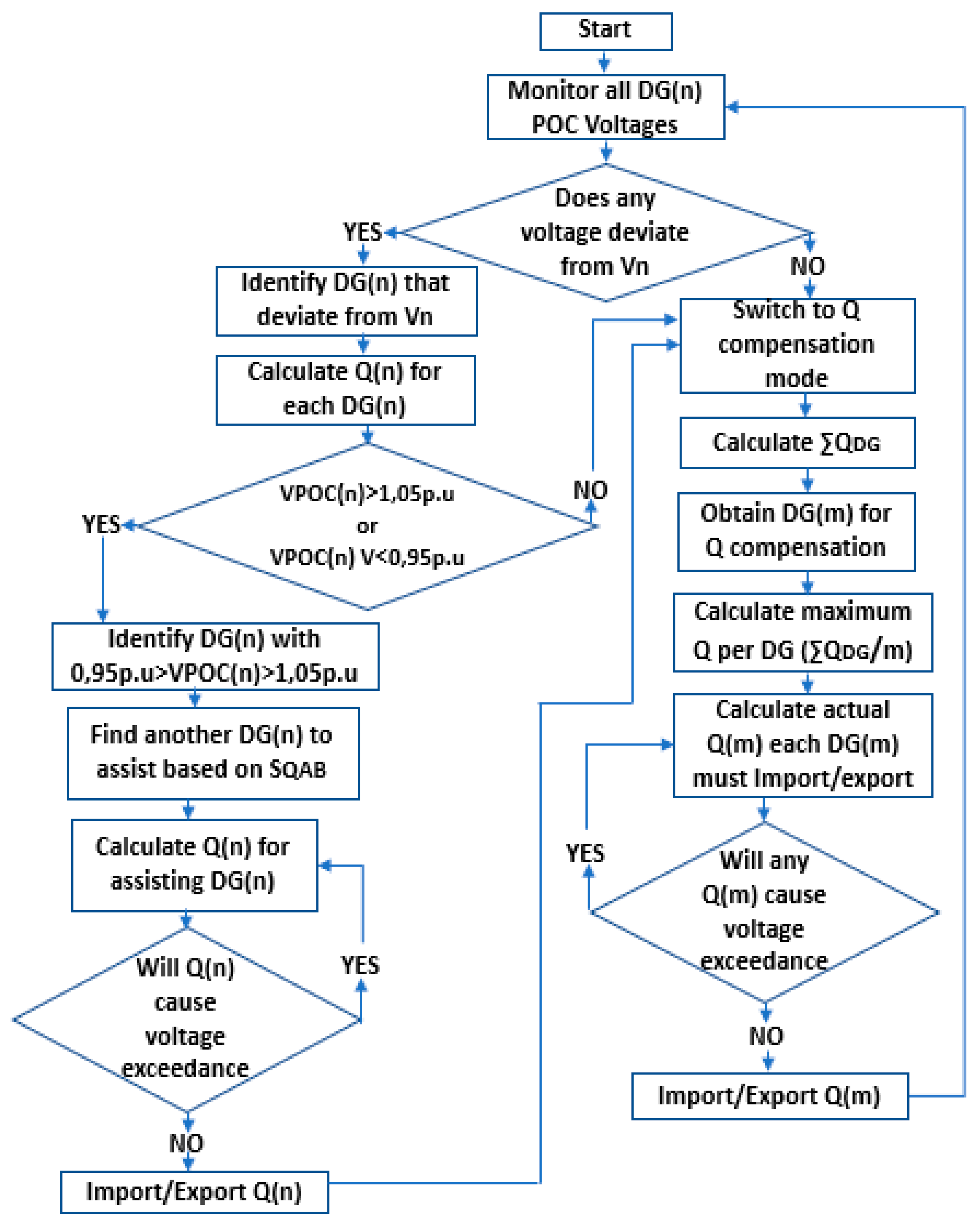
3.2. Proposed Control System
Step 1:
The control system measures voltage magnitudes
VPOC(n), where distributed generators are connected. The control system will then calculate the amount of reactive power each distributed generator must import/export based on Equations (12) and (13), where
QR is the required reactive power,
Vn is the nominal voltage, and
SQ is the sensitivity of voltage to dispatched reactive power, where the distributed generator is located. The value of
VMax is 1.05 p.u and that of
VMin is 0.95 p.u.
After giving all distributed generators instructions of the magnitude of reactive power they must export/import, the control system will further monitor the voltage magnitudes VPOC(n), where distributed generators are connected. If there is any distributed generator with a voltage magnitude above Vmax or below Vmin at its point of connection VPOC(n), the control system will move to step 2. If all points of connection voltage magnitudes are between 0.95 and 1.05 p.u, the control system will skip step 2 and continue to step 3.
Step 2:
When the control system detects a distributed generator point of connection voltage
VPOC(n) that is still above
Vmax or below
Vmin, it seeks other distributed generators in its database that can influence voltage magnitude where the struggling distributed generator experiencing a voltage magnitude higher than
Vmax or below
Vmin is connected. If a distributed generator has multiple distributed generators that can influence voltage where it is connected, the control system will select one with the highest sensitivity first and one with the lowest sensitivity last. Therefore, the control system will calculate the magnitude of reactive power the assisting distributed generator must export/import to suppress voltage magnitudes on the struggling generator’s point of connection. When calculating the reactive power the assisting generator must import/export, the control system will first assess the maximum reactive power possible based on the voltage where the assisting generator is connected using Equations (14) and (15), where
QPresent(B) is the reactive power the assisting generator is already exporting/importing,
SQB is the sensitivity of voltage to reactive power where the assisting generator is connected, and
VPOCB is the voltage where the assisting generator is connected.
The control system will use Equation (14) to compute the highest magnitude of reactive power that the assisting generator can possibly export and Equation (15) to compute the highest magnitude of reactive power the assisting generator can possibly import. Once the highest possible reactive power is calculated, the control system will then calculate the actual reactive power needed to suppress voltage magnitude where the struggling generator is connected based on Equations (16) and (17), where
VPOCA is the voltage where the struggling generator is connected and
SQBA is the sensitivity of voltage where the struggling generator is connected to the assisting generator reactive power.
The control system will then use the minimum value obtained between Equations (14) and (16) if the assisting generator is required to export reactive power and also use the maximum value obtained between Equations (15) and (17) if the assisting generator is required to import reactive power. The control system will also monitor voltage magnitudes to ensure that any reactive power that is imported/exported does not violate voltage limits. When step 2 is complete, the control system proceeds to step 3.
Step 3:
The control system will then scout all its distributed generators and select generators for reactive power compensation based on two conditions: those with a point of connection voltage magnitude between 0.95 and 1.05 p.u and importing/exporting a reactive power magnitude that is less than 40% of their rated reactive power. The control system will then use these distributed generators to compensate reactive power imported/exported on step 1 and step 2 and hence, improve power factor. Based on the voltage magnitude where each distributed generator is connected and the total reactive power that must be compensated, the control system will calculate the reactive power each distributed generator must export/import for reactive power compensation based on Equations (18)–(20).
The control system will first use Equation (18) to calculate the maximum reactive power each distributed generator must compensate, where
QTotal is the total reactive power imported/exported for voltage regulation and
m is the total number of distributed generators participating in reactive power compensation. The maximum reactive power each compensating distributed generator must import/export is calculated to avoid overcompensation, where the power factor will change from lagging to leading.
However, since the maximum reactive power required is not always possible due to capacity and voltage constraints, the control system will then calculate the actual reactive power each distributed generator must export/import based on Equations (19) and (20), where
QDG(n) is the reactive power a generator must import/export and
QPresent(n) is the reactive power the generator is exporting/importing before reactive power compensation.
When distributed generators are importing reactive power to suppress voltage, the control system will calculate the reactive power that must be exported by each of the compensating distributed generators based on the minimum value between Equations (18) and (19). When distributed generators are exporting reactive power to boost voltage magnitudes, the control system will calculate the reactive power each compensating distributed generator must import based on the maximum value between Equations (18) and (20). The reactive power compensation of step 3 will ensure that power factor that is reduced due to excessive import of reactive power by distributed generators has been improved. For ease of implementation and to reduce computational burden on the control system, the steps 1 to 3 of the control system were implemented using the fuzzy logic philosophy. The fuzzy logic controller was designed to replicate Equations (12)–(20) with acceptable precision.
Figure 1 illustrates the algorithm the proposed voltage regulation and power factor improvement system will follow.
4. Results and Analysis
To test the proposed control system, a South African power distribution network was modelled in MATLAB Simulink. The network has three 22 kV overhead lines supplied from the same substation, with impedance Z = 0.55 + j0.36. Line 1 is 25 km, line 2 is 36 km, and line 3 is 28 km long. The 22 kV distribution network is supplied by a 132 kV transmission line through a 132/22 kV transformer. The maximum rating of each distributed generator is 7 MW, 1.67 MVAR. This is designed in accordance with the grid connection code for renewable power plants connected to the electricity transmission system or distribution system in South Africa, which states that distributed generators of category B must have a minimum reactive power capability that is 22.8% of their rated active power [
32]. The set
Vmin will be 0.95 p.u and the set
Vmax will be 1.05 p.u. Most power utility companies around the world set their maximum allowed voltage deviation at 5% of the nominal voltage. However, the control algorithm can be set to work with any voltage deviation as
Vmin and
Vmax. The control system was then tested through several scenarios that explored different penetrations of distributed generation in a 22 kV power distribution network.
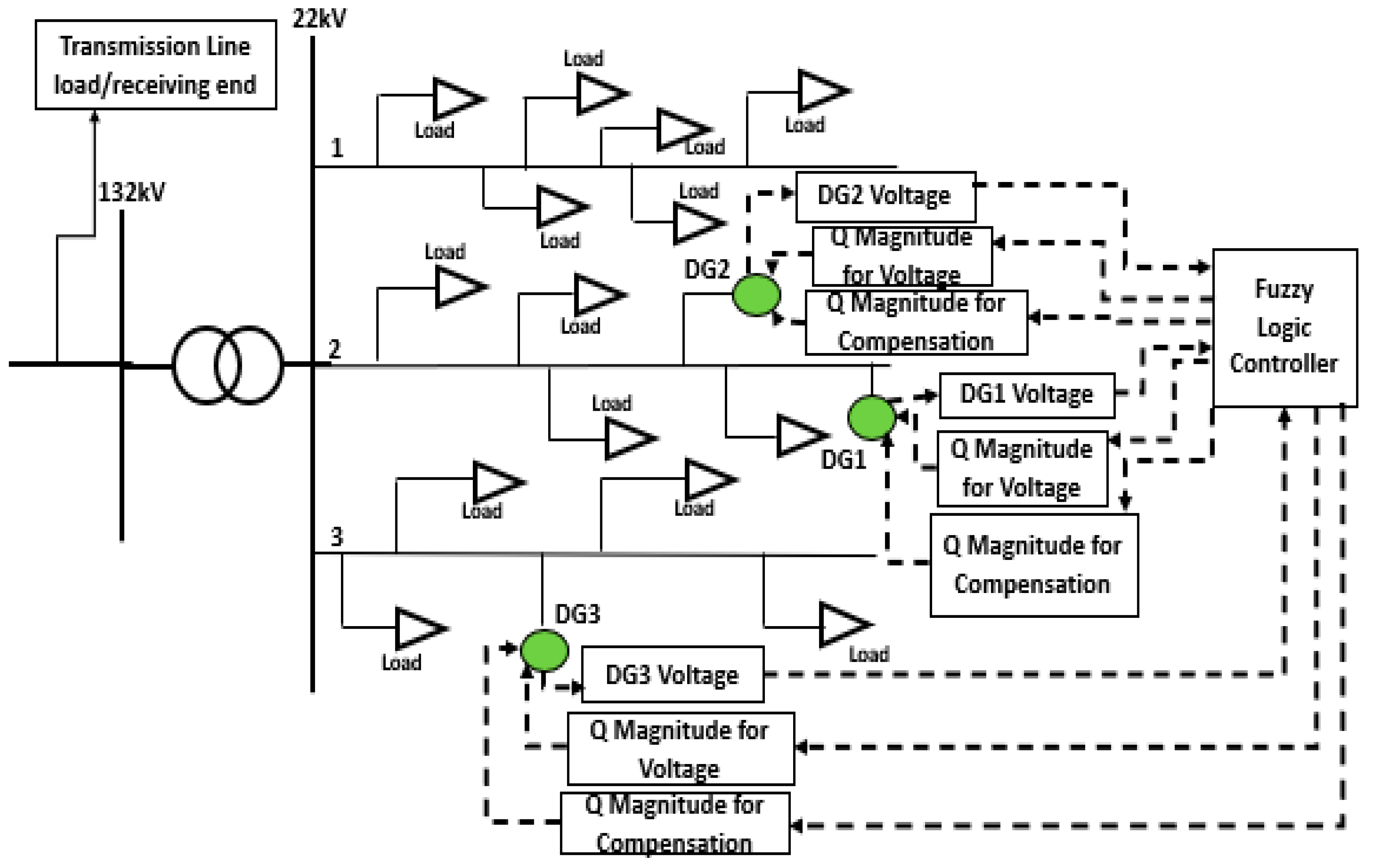
Figure 2 and
Figure 3 show a single line diagram of the network configuration, distributed generators, and the control system interconnections used to test the proposed system. The network configuration depicts a 132 kV line supplying a 132/22 kV transformer. The 132/22 kV transformer then supplies three 22 kV lines through a common 22 kV busbar. The fuzzy logic controller is then connected to all distributed generators and their respective points of connection.
4.1. Scenario 1: Distributed Generators Importing Reactive Power to Suppress Voltage Magnitudes and Power Factor Correction in a Network with 3 × 7 MW, 1.67 MVAR Generators
This scenario will evaluate a state of the network where distributed generators use reactive power to regulate voltage where they are connected. In addition, distributed generators that are not participating in extreme voltage regulation will use their reactive power capability for power factor correction. This is because distributed generators reduce the power system power factor when they import reactive power to regulate voltage. The power factor will be measured at the load end of the transmission line before the 132/22 kV transformer, as indicated in
Figure 2.
Table 1 shows the initial conditions before the proposed control system is implemented. The simulations were performed using MATLAB Simulink R2016a.
As shown in
Table 1, when distributed generators are exporting active power and importing no reactive power, generators 1 and 2 points of connection (POC) voltages are at 1.071 and 1.079 p.u, respectively. At this point, the power factor is 0.98, which is close to unity. At this stage, the control system analysed the network voltage magnitudes where distributed generators are connected. It then calculated the reactive power magnitude each distributed generator must import/export based on their point of connection voltage and sent the instructions to the respective distributed generators.
Table 2 shows the results.
Generators 1 and 2 imported 1.03 and 1.32 MVAR, respectively, bringing the voltage magnitude down to 1.04 and 1.046 p.u, respectively. Generator 3 only exported a slight amount of reactive power at 0.17MVAR, since the voltage magnitude where it was connected had dropped slightly below nominal voltage when generators 1 and 2 imported reactive power. Besides reducing voltage magnitudes, the import of reactive power by distributed generators 1 and 2 also reduced the power factor from 0.98 to 0.88 on the load end of the transmission line. Since there was no point of connection voltage that was above 1.05 p.u, the control system skipped step 2 and proceeded to step 3. To drive back the power factor towards unity, the control system prompted generator 3 to compensate reactive power imported by generators 1 and 2. The control system’s decision to utilise generator 3 for power factor improvement was based on the assessment that generator 3 did not experience a voltage magnitude that exceed 1.05p.u or below 0.95p.u at its point of connection and was exporting 0.17MVAR, which is 10% of its rated reactive power.
The control system then calculated that the maximum reactive power that generator 3 must export to fully compensate generators 1 and 2 is 2.35 MVAR.
Table 3 shows the results.
However, generator 3 could not export 2.35 MVAR due to the 1.67 MVAR rated capacity of the distributed generator. Since generator 3 voltage magnitude was almost at nominal voltage, the control system recalculated that distributed generator 3 should export 1.67 MVAR and send the instruction to generator 3 for implementation. As shown in
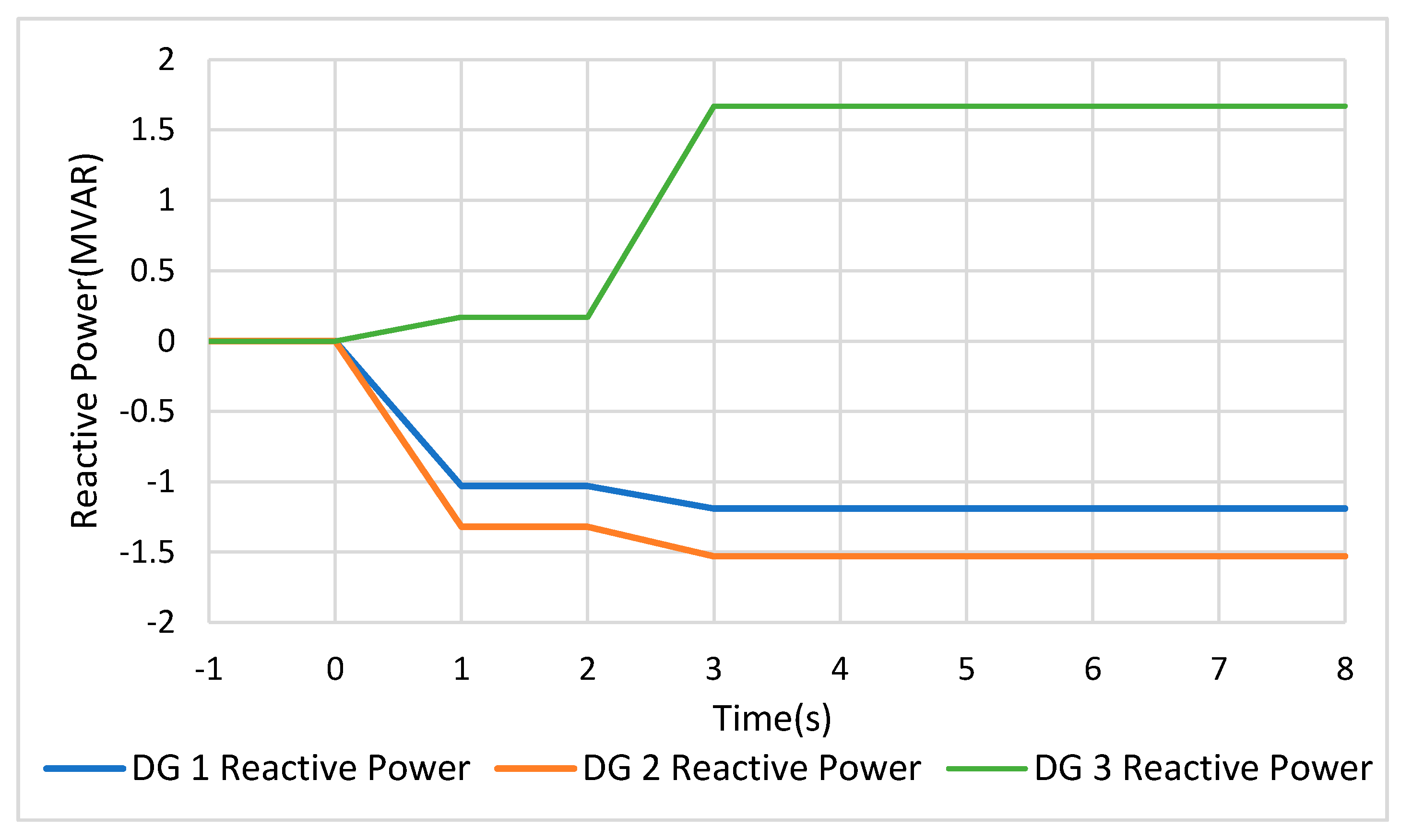
Table 3, generator 3 exported 1.67 MVAR and hence, improved the power factor from 0.88 to 0.95. The losses also reduced from 2.21 to 1.88 MVAR. The continuous operation of scenario 1 is shown in
Figure 4,
Figure 5,
Figure 6 and
Figure 7.
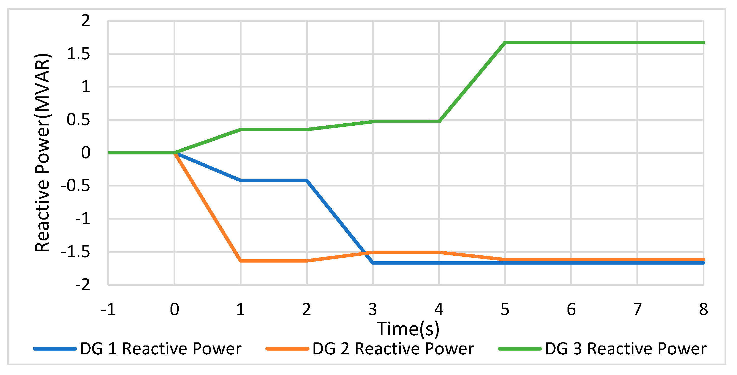
In
Figure 4, all distributed generators were initially at 0 MVAR. In a voltage regulation effort, distributed generators 1 and 2 imported 1.03 and 1.32 MVAR, respectively, at
t = 0 s based on the reactive power values calculated by the control system. At
t = 2 s, generator 3 exported 1.67 MVAR to improve power factor as instructed by the control system. When generator 3 exported 1.67 MVAR, the network voltage increased slightly. Therefore, the control system recalculated the reactive power magnitude imported by generators 1 and 2 to slightly higher values of 1.19 and 1.53 MVAR, respectively.
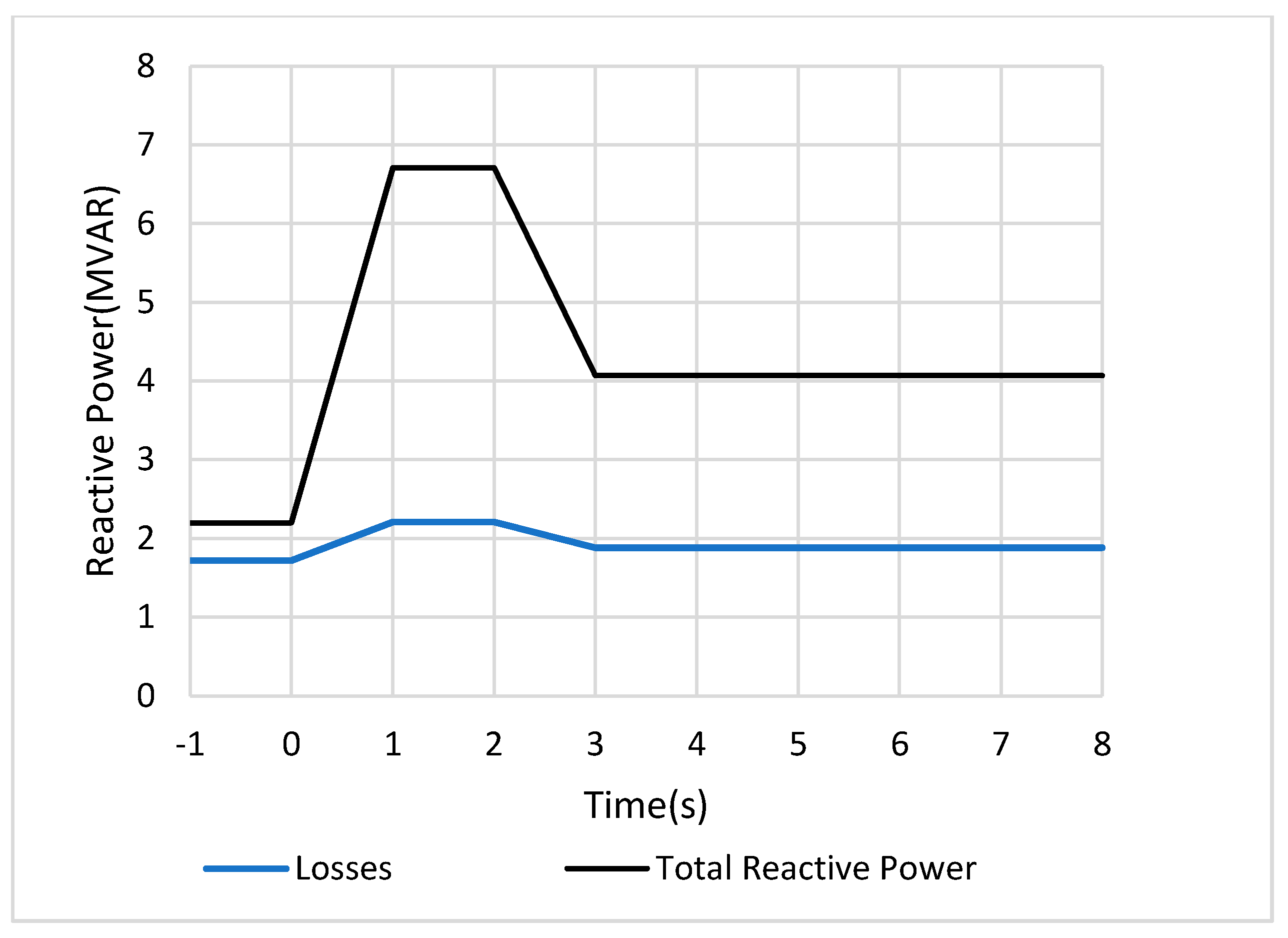
When distributed generators 1 and 2 imported reactive power for voltage regulation at
t = 0 s, the reactive power demand increased from 2.20 to 6.71 MVAR, as shown in
Figure 5. However, when generator 3 exported reactive power to supply the reactive power imported by generators 1 and 2 at
t = 2 s, the reactive power demand decreased from 6.71 to 4.07 MVAR.
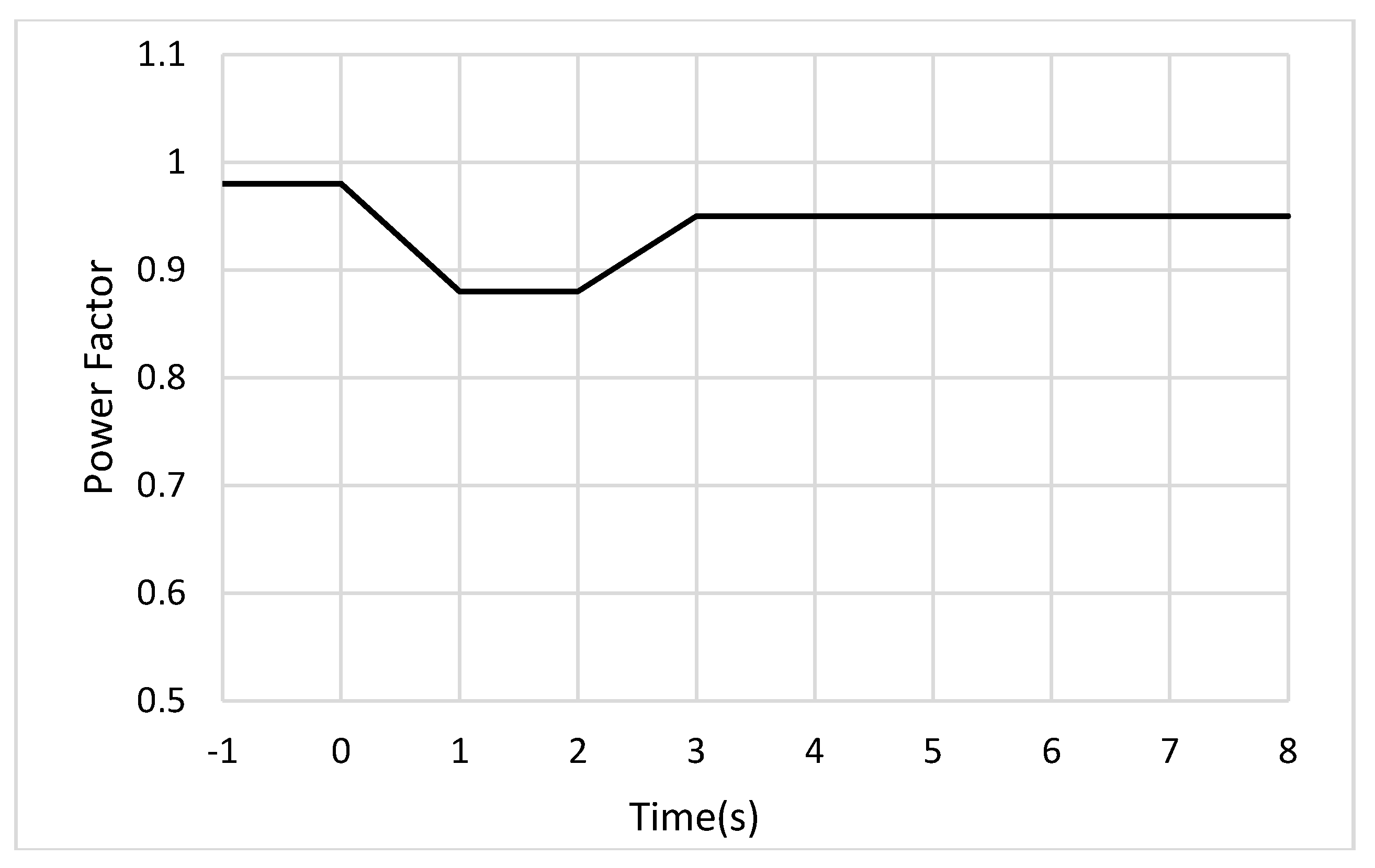
When the reactive power demand on the power system increased from 2.20 to 6.71 MVAR as distributed generators 1 and 2 imported reactive power at
t = 0 s, the power factor dropped from 0.98 to 0.88. However, when generator 3 exported reactive power at
t = 2 s, the power factor improved from 0.88 to 0.95, as shown in
Figure 6.
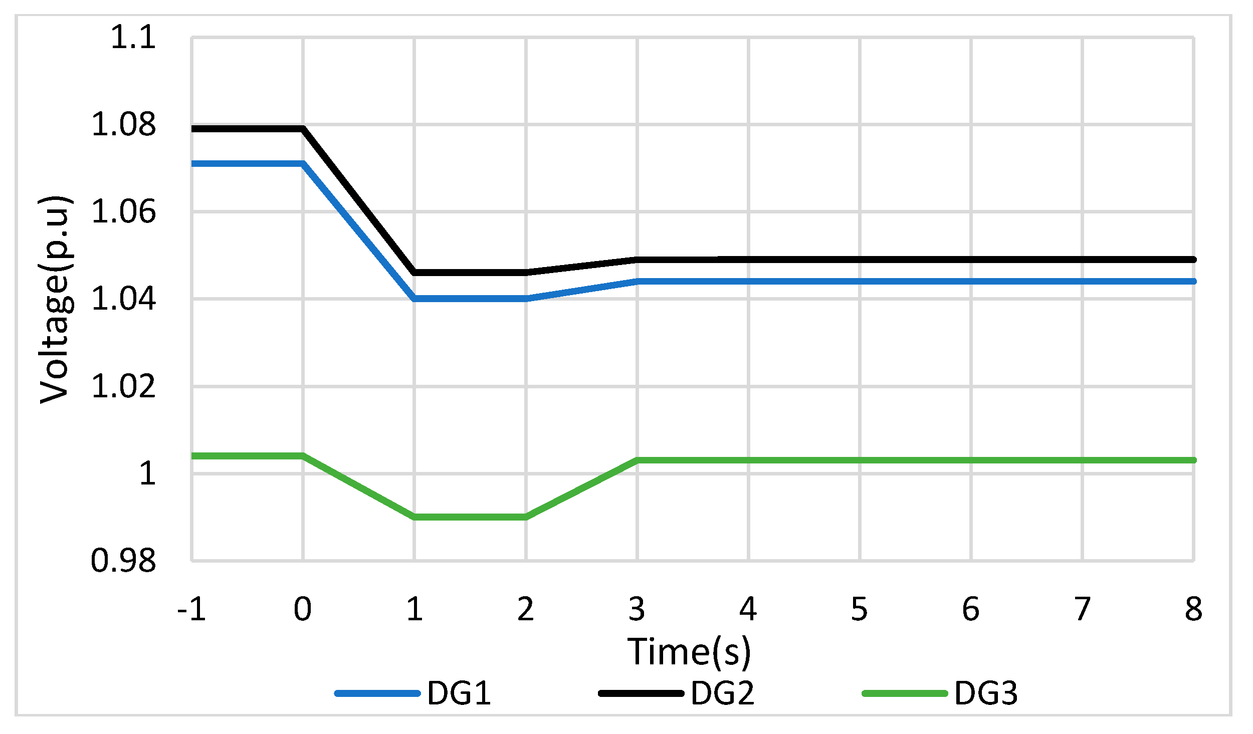
Figure 7 shows the behaviour of the points of connection voltage magnitudes as distributed generators import reactive power. When generators 1 and 2 imported reactive power for voltage regulation at
t = 0 s, the voltage magnitudes dropped significantly. When generator 3 exported reactive power for power factor improvement at
t = 2 s, its point of connection voltage increased. However, since the sensitivity of generator 3’s reactive power to generators 1 and 2 voltage magnitudes was minor, the voltage magnitudes where generators 1 and 2 were connected only showed a very slight increase when generator 3 exported reactive power for power factor improvement. This slight increase in voltage where generators 1 and 2 are connected prompted the control system to recalculate their reactive power import, as explained in
Figure 4.
Therefore, the proposed control system is an intelligent system that constantly assesses the status of all its distributed generators and decides which role each distributed generator must play, either voltage regulation or power factor improvement. The control system further calculates the reactive power output of each distributed generator based on network conditions and the role the distributed generator is playing. As demonstrated in scenario 1, the control system utilised generators 1 and 2 for voltage regulation and then, utilised generator 3 for power factor improvement.
Hence, the proposed control system can regulate voltage magnitudes and improve power factor without the need of additional devices like capacitor banks and reactors.
4.2. Scenario 2: Distributed Generator 1 Importing Reactive Power to Suppress Voltage Magnitudes where Distributed Generator 2 Is Connected in a Network with 3 × 7 MW, 1.67 MVAR Distributed Generators
This scenario will explore a set-up in which a distributed generator cannot keep voltage magnitudes within acceptable limits at its point of connection and hence, the control system finds another distributed generator to assist. The initial conditions of the network are shown in
Table 4.
As in the previous scenario, the control system calculated the reactive power each distributed generator must import/export based on their point of connection voltage and sent the instructions. All generators then imported/exported reactive power based on the received instruction. This is shown in
Table 5.
All points of connection voltage magnitudes dropped below 1.05 p.u, except that of generator 2. Upon realising that generator 2 had imported all its reactive power capacity but the voltage was still above 1.05 p.u at 1.062 p.u, the control system then moved to step 2 and instructed generator 1 to further import reactive power. The decision was based on the information the control system had that generator 1 can influence voltage magnitudes where generator 2 is connected. Based on the voltage magnitude where generator 1 is connected, the voltage magnitude where generator 2 is connected, the reactive power that generator 1 is already importing, and the maximum reactive power generator 1 can import. The control system calculated the reactive power that generator 1 should import to assist generator 2. This is shown in
Table 6.
Generator 1 then imported an extra 1.25 MVAR in addition to the reactive power it was already importing. This action reduced the voltage magnitude where generator 2 was connected, from 1.062 to 1.049 p.u. However, the effort by distributed generators to suppress voltage magnitudes increased the network reactive power from 1.89 to 8.002 MVAR and reduced the power factor from 0.98 to 0.85. The control system then moved to step 3. The control system classified generator 3 as an idling generator, since its point of connection voltage was between 0.95 and 1.05 p.u and exporting 0.47 MVAR which was 28% of its reactive power rating. The control system then instructed generator 3 to compensate the reactive power imported by generators 1 and 2 and hence, improve the power factor. The control system then calculated that generator 3 must export a maximum of 3.05 MVAR to fully compensate generators 1 and 2. However, the maximum rated reactive power of generator 3 limited the calculated maximum reactive power. This is shown in
Table 7.
Generator 3 was, therefore, instructed to export 1.67 MVAR by the control system to compensate for generators 1 and 2 imported reactive power. This action improved the power factor from 0.85 to 0.93. In addition, this reduced the losses from 2.56 to 2.19 MVAR.
Figure 8,
Figure 9,
Figure 10 and
Figure 11 show the continuous operation of the power distribution network for scenario 2.
As shown in
Figure 8, at
t = 0 s, generators 1 and 2 imported reactive power to regulate voltage magnitudes. At the same time, generator 3 exported a slight magnitude of reactive power, since the voltage magnitude where it was connected was slightly below nominal voltage at 0.990 p.u. At
t = 2 s, generator 1 increased its reactive power import from 0.42 to 1.67 MVAR. This was as per the control system’s instruction in an effort to further reduce voltage where generator 2 was connected. However, as the voltage where generator 2 is connected drops below 1.05 p.u, the controller instructed generator 2 to slightly reduce reactive power import from 1.64 to 1.50 MVAR. This is to avoid importing unnecessary magnitudes of reactive power and further worsening of the power factor.
At t = 4 s, generator 3 exported 1.67 MVAR to improve the power factor, during the same time, generator 2 slightly increased reactive power import. Generator 2 was instructed by the control system to increase its reactive power import as the network voltage had risen slightly when generator 3 exported reactive power for power factor improvement.
As depicted in
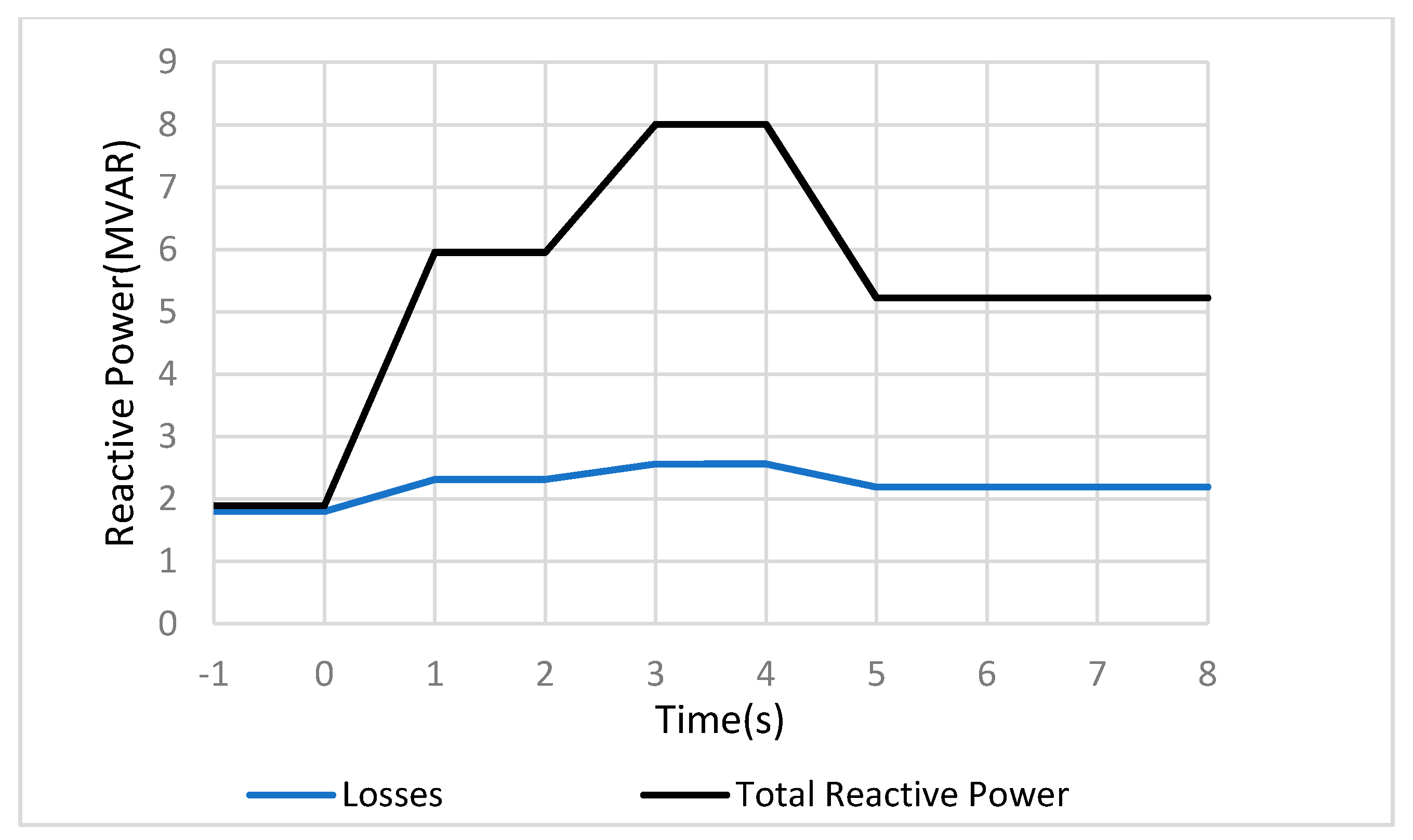
Figure 9, when generators 1 and 2 imported reactive power to regulate voltage, the power system reactive power demand increased from 1.89 to 8.002 MVAR. However, the export of reactive power by generator 3 reduced the reactive power demand from 8.002 to 5.22 MVAR.
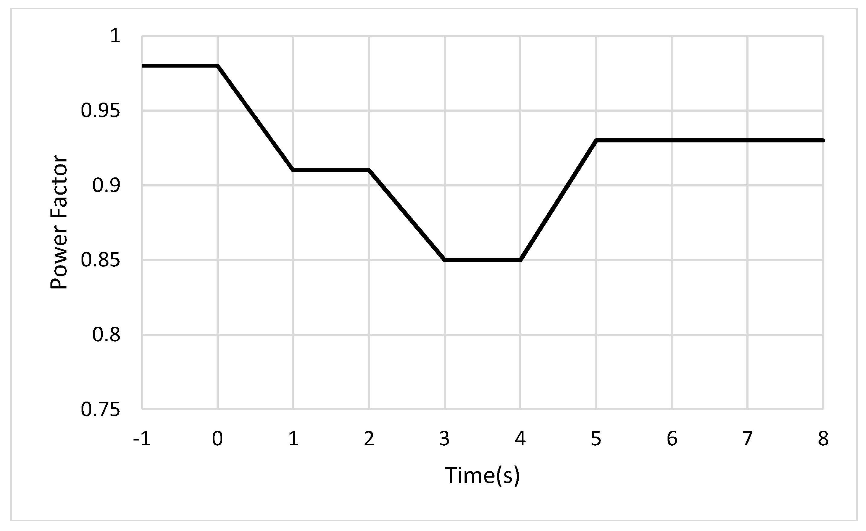
As depicted in
Figure 10, when generators imported reactive power for voltage regulation at
t = 0 s, the power factor dropped from 0.98 to 0.91. In addition, when generator 1 assisted generator 2 by importing more reactive power at
t = 2 s, the power factor further dropped from 0.91 to 0.85. However, the export of reactive power by generator 3 at
t = 4 s improved power factor from 0.85 to 0.93.
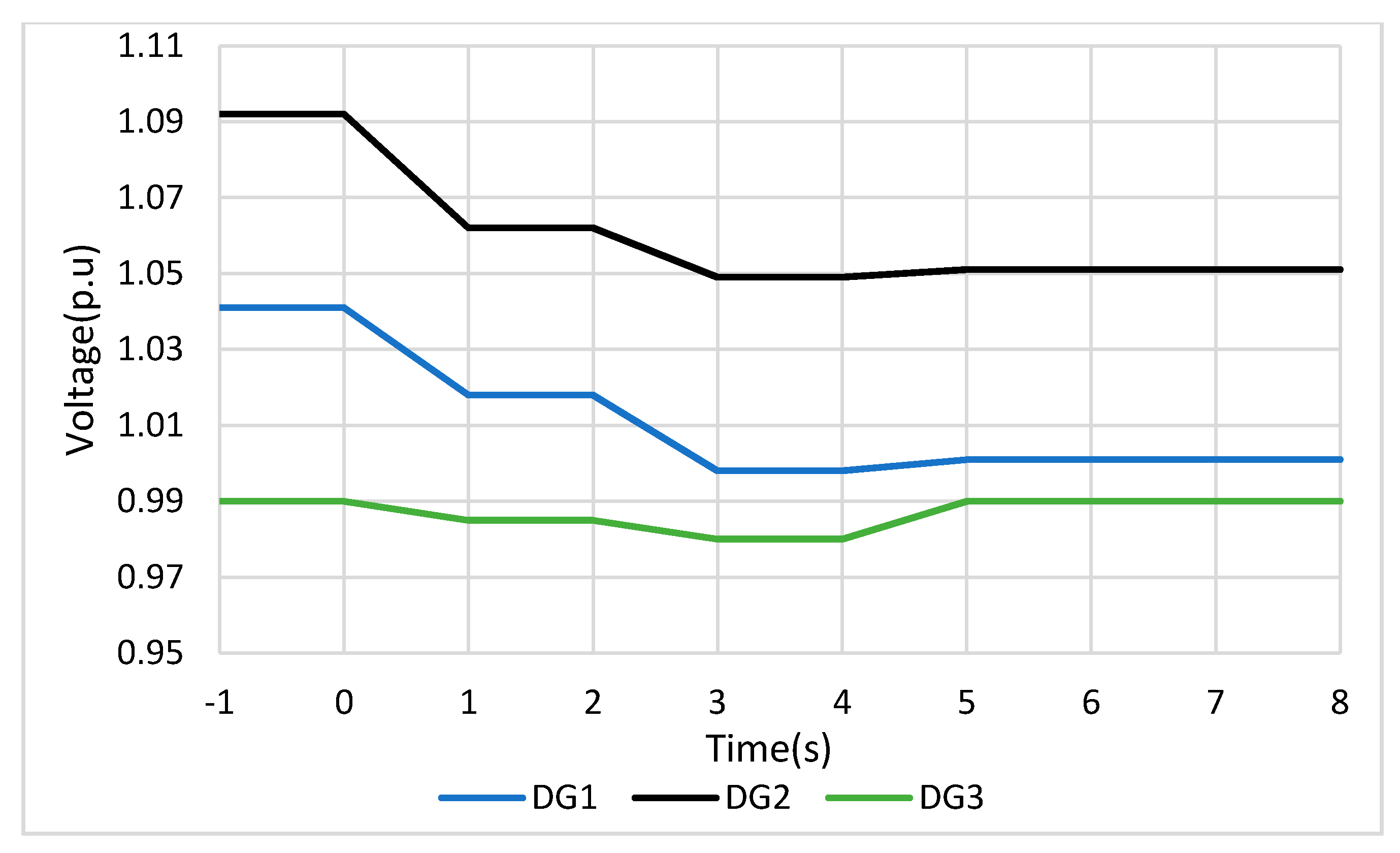
As depicted in
Figure 11, the import of reactive power by generators 1 and 2 at
t = 0 s and
t = 2 s drastically reduced voltage magnitudes where they were connected. The export of reactive power by generator 3 for power factor improvement did not affect voltage magnitudes where generators 1 and 2 were connected, since there was poor sensitivity between voltage at generators 1 and 2 points of connection and the reactive power of generator 3.
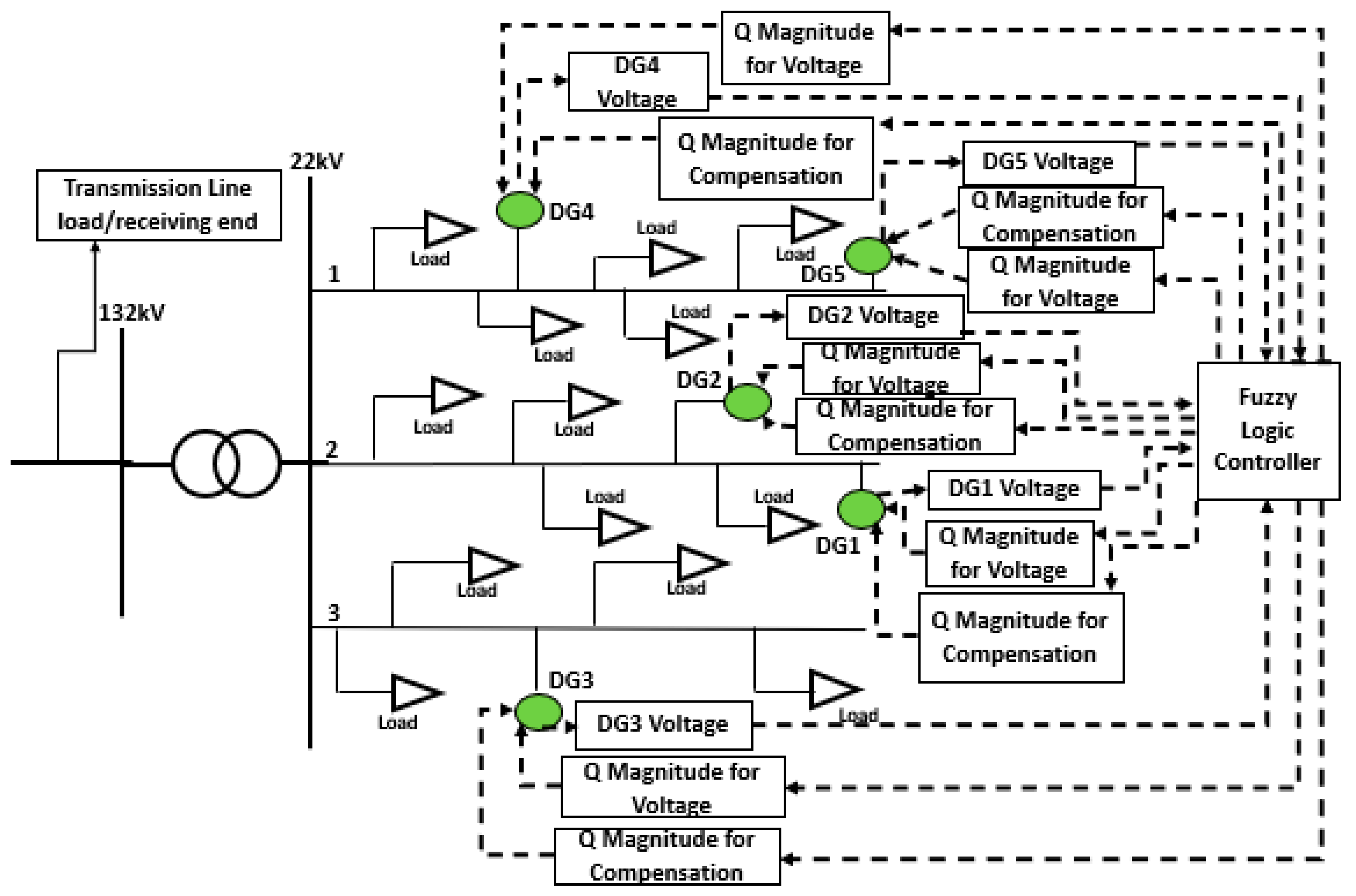
4.3. Scenario 3: Distributed Generators Importing Reactive Power to Suppress Voltage Magnitudes and Power Factor Correction in a Network with 5 × 7 MW, 1.67 MVAR Generators
To show the effect of more generators on the power system power factor, two more distributed generators were added and hence, a network with five distributed generators, as shown in
Figure 3, was assessed. When two more distributed generators were connected, the active power flowing through the transmission line decreased as more active power was generated within the distribution network. As in previous scenarios, the power factor will be measured at the load end of the transmission line.
Table 8 shows the initial status of the network before reactive power export/import.
As in previous scenarios, the control system calculated the amount of reactive power each distributed generator must import/export based on the voltage magnitudes where the generator was connected. The results are shown in
Table 9.
When all generators were importing reactive power based on their local measurements, as shown in
Table 9, generator 2 point of connection voltage was still above 1.05 p.u at 1.053 p.u. The total reactive power being transmitted through the transmission network at this point was 6.2MVAR; this increase from 0.89 to 6.2 MVAR caused the power factor to drop from 0.99 to 0.77. The control system then moved to step 2 to fix the voltage where generator 2 was connected. The control system then searched for a distributed generator which had influence on the voltage where generator 2 was connected, and it found distributed generator 1. The control system then calculated the amount of reactive power generator 1 must import to regulate voltage where generator 2 was connected based on the voltage magnitude where generator 1 was connected, the voltage magnitude where generator 2 was connected, and the amount of reactive power generator 1 was already importing. The results are shown in
Table 10.
The control system then calculated that generator 1 must import an extra 1.22 MVAR to assist generator 2 with voltage regulation. Generator 1 then imported a total reactive power of 1.36 MVAR, and this reduced the voltage magnitude where generator 2 was connected to 1.046 p.u. However, importing extra reactive power increased the transmission line reactive power to 7.96 MVAR and hence, further reducing the power factor to 0.67. Since the voltage regulation process was complete, the control system then focused on power factor correction. The control system then searched for distributed generators that could compensate for the reactive power that was being imported for voltage regulation purposes. Since distributed generators 3 and 4 had voltage magnitudes between 0.95 and 1.05 p.u and importing/exporting only 8% and 17% of their rated reactive power, respectively, they were selected by the control system for power factor improvement. The control system then calculated that generators 3 and 4 must export a maximum of 1.83MVAR each to fully compensate generators 1, 2, and 5. However, the reactive power capacity and voltage magnitudes limited the maximum reactive power from being exported. Therefore, the control system recalculated the new reactive power values for generators 3 and 4. The results are shown in
Table 11.
The control system then calculated that generators 3 and 4 must export 1.33 and 1.67 MVAR, respectively, for power factor improvement. This improved the power factor from 0.67 to 0.90. The losses also reduced from 1.50 to 0.92 MVAR. The continuous operation for scenario 3 is shown in
Figure 12,
Figure 13,
Figure 14 and
Figure 15.
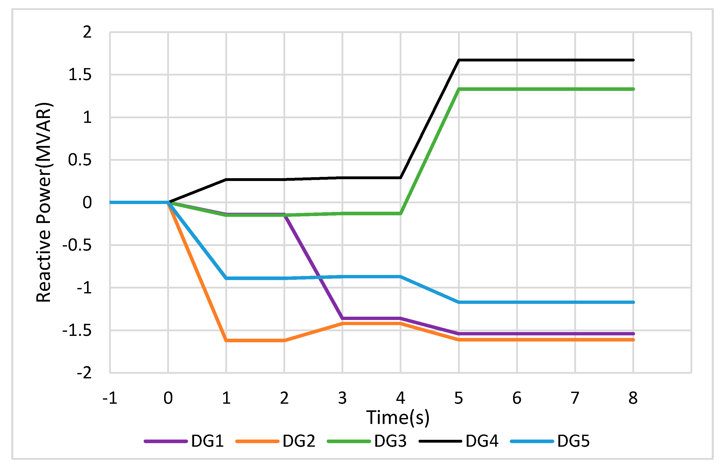
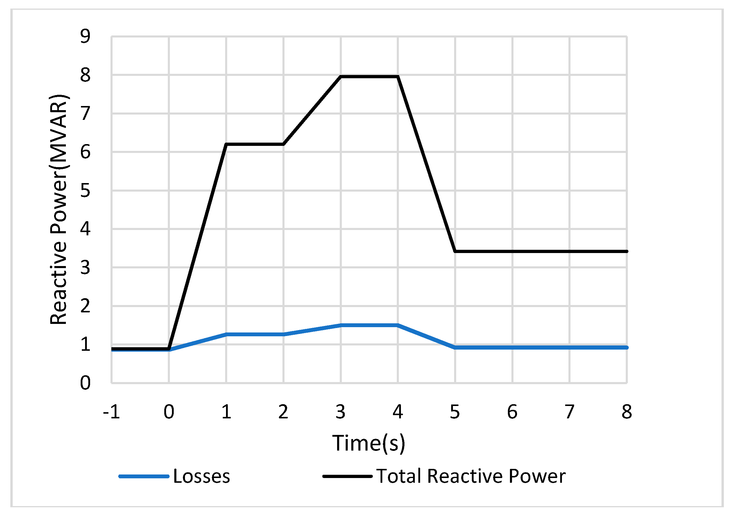
Figure 12 shows the reactive power response for scenario 3. As depicted, generators 2 and 5 imported a significant amount of reactive power for voltage regulation at 1.62 and 0.89 MVAR, respectively, at
t = 0 s. When generator 2 could not reduce its point of connection voltage below 1.05 p.u, the control system calculated and instructed generator 1 to increase reactive power import from 0.14 to 1.36 MVAR at
t = 2 s. However, as the voltage where generator 2 was connected fell below 1.05 p.u, generator 2 was instructed to reduce reactive power import slightly from 1.62 to 1.42 MVAR to avoid unnecessary import of reactive power, which would further worsen the power factor. At
t = 4 s, generators 3 and 4 were instructed to export 1.33 and 1.67 MVAR, respectively, for power factor improvement. At the same time, generators 1, 2, and 5 increased reactive power import to suppress voltage magnitudes, since the export of reactive power by generators 3 and 4 slightly increased network voltage magnitudes.
As depicted in
Figure 13, the import of reactive power at
t = 0 s increased the power system reactive power demand from 0.89 to 6.2 MVAR. When generator 1 imported more reactive power at
t = 2 s to assist generator 2, the reactive power demand further increased to 7.96 MVAR. The export of reactive power by generators 3 and 4 for power factor improvement reduced the reactive power demand from 7.96 to 3.42 MVAR.
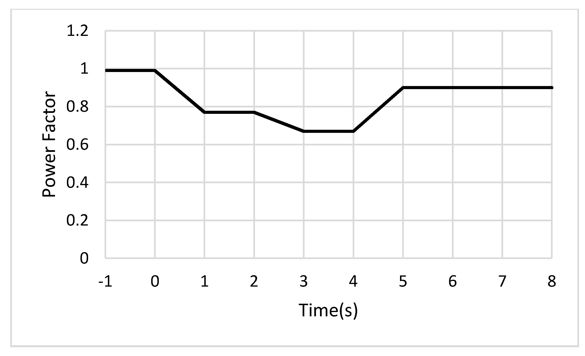
The power factor was also responding to the changing reactive power demand, as illustrated in
Figure 14. The increase in the reactive power demand at
t = 0 s decreased the power factor from 0.99 to 0.77. The further increase in reactive power demand at
t = 2 s further decreased the power factor from 0.77 to 0.67. However, the export of reactive power by generators 3 and 4 for power factor correction improved the power factor from 0.67 to 0.90.
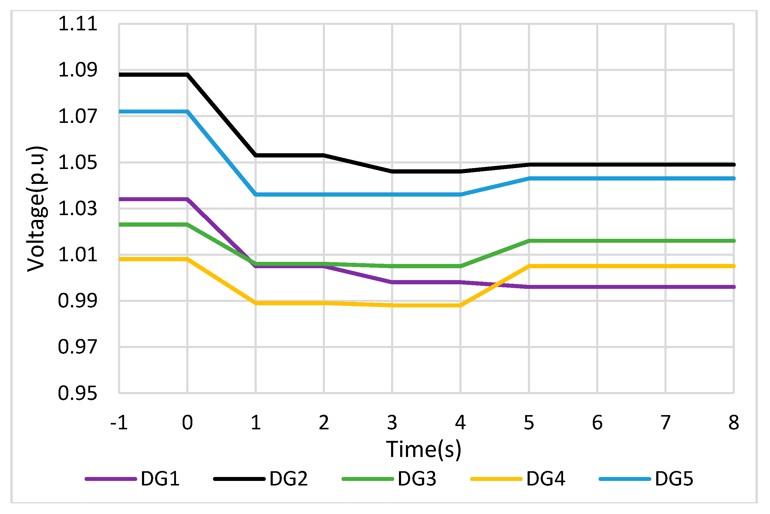
As generators regulated voltage and improved power factor through the import and export of reactive power, the voltage magnitudes at their points of connection were also responding in relation to the sensitivity of voltage magnitude to reactive power, as portrayed in
Figure 15.
In scenario 3, the control system enabled voltage regulation by calculating the amount of reactive power each generator must import/export based on the voltage magnitude where it was connected. When other generators could not successfully regulate voltage below 1.05 p.u, the control system found generators that could help and calculate the additional reactive power that must be imported to help the struggling generator. In conclusion, the control system found generators that it could use for power factor correction and also calculated the amount of reactive power each generator must export to compensate the reactive power that was imported by other generators for voltage regulation purposes. Therefore, through the described procedure, the control system can successfully regulate voltage and improve power factor without the need of reactive power compensation devices like capacitors and reactors in the network.
In addition, the use of three and five generators for testing the control system proved that the control system could operate despite the number of generators connected. The work conducted in this paper has proved the hypothesis raised in the introduction section that the import of reactive power by distributed generators in effort to regulate voltage will reduce the power factor. However, through the control system proposed in this paper, the power factor that was reduced by the effect of distributed generators importing reactive power to regulate voltage can be improved. Therefore, the proposed control system can simultaneously regulate voltage and improve power factor in a power system that has multiple distributed generators connected.
5. Conclusions
Distributed generators are being connected into the existing power system at a high rate. This is because of the negative impact of fossil fuel-fired power stations on our environment. Although these distributed generators provide clean energy, they also introduce certain problems to the power system, including increased voltage magnitudes and reverse power flow. Increased voltage magnitudes are a threat to power system stability and millions of devices connected to it; therefore, effective voltage regulation is critical to any power system. Modern distributed generators are designed with a reactive power capability. Therefore, through reactive power, distributed generators can suppress or boost voltage magnitudes where they are connected. Using the distributed generator’s reactive power capability for voltage control has also been recommended in multiple literature works. To suppress voltage magnitudes, a generator must import reactive power from the power system. When a generator imports reactive power from the power system, it then becomes an inductive load to the power system.
This increases the total reactive power that a power system must supply, reduces the power factor, and increases the total losses in the network. According to the knowledge of the author, there is no work in the literature that has been done that provides a plan to mitigate the possible reduction in power factor due to multiple distributed generators importing reactive power simultaneously. As a result, this paper proposed an innovative control system based on the fuzzy logic philosophy that coordinates distributed generators such that they decrease reactive power that is flowing through the transmission network while keeping voltage magnitudes well regulated. When the reactive power being transmitted through the transmission network is reduced, the power factor also improves.
The proposed control system prioritised voltage regulation, and any distributed generator that detected a high voltage magnitude where it is connected imported reactive power.
When it could not reduce the voltage magnitude to acceptable levels, the control system enabled a distributed generator closer to it to assist. All generators that have no voltage problem where they are connected and also importing/exporting slight magnitudes of reactive power would export reactive power to supply those generators that are importing huge magnitudes of reactive power. Therefore, the reactive power imported by a distributed generator for voltage regulation purposes will be supplied locally by another distributed generator. This will reduce reactive power being transmitted through the transmission network, reduce network losses, and improve power factor. A South African 22 kV network was modelled and used to test the proposed control system. As shown in scenarios 1, 2, and 3, the power factor dropped to 0.88, 0.85, and 0.67, respectively, when distributed generators imported reactive power to regulate voltage. However, the reactive power compensation technique initiated by the control system managed to improve the power factor of scenarios 1, 2, and 3 to 0.95, 0.93, and 0.90, respectively. Therefore, the analysis of results revealed that the fuzzy logic-based control system works effectively in regulating voltage magnitudes and improving the power factor. The control system improved power factor without any capacitor bank or reactors available. In addition, the results show that the control system can operate with any number of distributed generators.


