Performance Study on Methanol Steam Reforming Rib Micro-Reactor with Waste Heat Recovery

1
Key Laboratory of Low-grade Energy Utilization Technologies and Systems, Chongqing University, Ministry of Education, Chongqing 400044, China
2
School of Energy and Power Engineering, Chongqing University, Chongqing 400030, China
*
Author to whom correspondence should be addressed.
Energies 2020, 13(7), 1564; https://doi.org/10.3390/en13071564
Submission received: 11 March 2020
/
Revised: 25 March 2020
/
Accepted: 26 March 2020
/
Published: 27 March 2020
(This article belongs to the Special Issue Advances in Hydrogen Energy)
Abstract
:Automobile exhaust heat recovery is considered to be an effective means to enhance fuel utilization. The catalytic production of hydrogen by methanol steam reforming is an attractive option for onboard mobile applications, due to its many advantages. However, the reformers of conventional packed bed type suffer from axial temperature gradients and cold spots resulting from severe limitations of mass and heat transfer. These disadvantages limit reformers to a low efficiency of catalyst utilization. A novel rib microreactor was designed for the hydrogen production from methanol steam reforming heated by automobile exhaust, and the effect of inlet exhaust and methanol steam on reactor performance was numerically analyzed in detail, with computational fluid dynamics. The results showed that the best operating parameters were the counter flow, water-to-alcohol (W/A) of 1.3, exhaust inlet velocity of 1.1 m/s, and exhaust inlet temperature of 773 K, when the inlet velocity and inlet temperature of the reactant were 0.1 m/s and 493 K, respectively. At this condition, a methanol conversion of 99.4% and thermal efficiency of 28% were achieved, together with a hydrogen content of 69.6%.
1. Introduction
Motor vehicles are increasing dramatically with the rapid economic development [1,2]. However, the power used by the internal combustion engine for power output generally accounts for only 30%–45% (diesel) or 20%–30% (gasoline) of the total fuel combustion heat. A car effectively uses only a small part of the fuel’s chemical energy, and most is lost through the engine’s cooling water and high-temperature exhaust heat [3,4]. Therefore, the exhaust heat recovery, which is very important to improve the fuel efficiency, attracts more and more attention [5,6]. Pashchenko [7] studied thermochemical recovery of heat contained in flue gases with steam methane reforming. It was found that the enthalpy increased with increasing mole fraction of combustion products in the reaction mixture. At the same time, the greenhouse effect resulting from the burning of fossil energy has seriously affected the earth. In this regard, many countries are actively investing in the development of pollution-free clean energy and alternative energy [8,9,10]. Hydrogen is one of the prominent alternative energy because of its many excellent properties, especially its combustion product of water [11,12]. However, difficulties in storage and ecological environment transportation of hydrogen persist [13,14]. Liquid fuel reformation is becoming an increasingly important process of hydrogen production for on-board mobile applications [15,16]. The use of bioethanol in the schemes of thermochemical recovery of heat contained in exit flue gases is also an option that was considered [17]. It was found that the degree of ethanol conversion is near unity above the temperature of 600 K. Pashchenko [18] compared thermochemical waste-heat recuperation through steam reforming of liquid biofuels. The maximum transformation coefficient 1.187 was observed for ethanol steam reforming, and a minimum effective temperature of about 600 K was observed for methanol. Methanol, which can be converted to hydrogen at lower temperature as it contains no carbon–carbon bonds, is an excellent hydrogen carrier and is free of storage and transportation issues [19,20]. In addition, methanol can be reformed to produce hydrogen at low temperatures, with very small amount of CO in the products [21]. Hydrogen production processes are numerous, and decisions on the choice of fuel are made based on which parameter is deemed most important for the system. Among various hydrogen production technologies, hydrogen production from methanol steam reforming (MSR) has attracted attention in the industry, due to its mild reaction and high hydrogen content of products.
Hydrogen production from endothermic MSR heated by exhaust can recover waste heat of the exhaust, increasing the fuel utilization. At the same time, the hydrogen from MSR can be sent to the internal combustion engine, which improves fuel combustion efficiency [22]. Thus, MSR heated by exhaust is considered to be an effective form of waste heat recovery [23,24]. Mishra [25] designed an experimental system for hydrogen production from MSR heated by automobile exhaust, and mainly studied the effects of hydrogen flow rate and exhaust heat exchange rate, on exhaust composition and reaction performance, under different conditions. The results showed that when the throttle opening is within 20%, the exhaust temperature and heat flow can meet the needs of hydrogen production from MSR. Methanol conversion increases with the heat exchange efficiency of reformers, and heat recovery increases with increasing engine speed. However, too high an engine speed will cause the heat exchange efficiency to decrease. Kumar [26] used flow-through tubular heat exchanger and porous ceramic reactors to enhance the heat transfer, and studied hydrogen production from MSR heated by exhausts. The results showed that the methanol conversion increased with the increasing temperature of the exhaust. At exhaust temperatures of 350 °C, the hydrogen volume fraction was approximately 42%. This method can provide hydrogen for on-board applications in an internal combustion engine, greatly improving the thermal efficiency of the system. Wang [27] studied the characteristics of the MSR-coupled with thermoelectric generator system heated by automobile exhausts. The results showed that when the temperature difference between the cold and hot ends of the thermoelectric module was 22 K, the output voltage of the power chip was 55 mV, the methanol conversion was 72.6%, and the molar fraction of hydrogen was 62.6%.
The packed bed is widely used for the conventional MSR method. However, the packed bed was reported to suffer from axial temperature gradients and cold spots [28,29]. These problems, which lead to thermal stresses in the channels, result from the severe limitations of mass and heat transfer. The stability and durability of the catalyst are significantly affected by the thermal stresses. Furthermore, the severe transfer resistance led to an effectiveness factor of the catalyst that is typically less than 5% in conventional steam reformers [30]. Micro-reactors can offer a higher heat transfer rate than the traditional chemical reactors, benefit from the high surface-to-volume ratio and short conduction paths [31]. Since the small diameters of the reactor channels can shorten the radial diffusion time, a high heat transfer coefficient is acquired. Moreover, the heat transfer coefficient is known to beneficial for the homogeneously catalyzed reaction [32]. Thus, microreactors have been increasingly seen as new tools for chemistry and chemical processes in recent years. Zhou [33] improved hydrogen production efficiency through sintered copper microreactors. Liang [34] studied the effect of the novel high-pressure propulsion on hydrogen production from MSR. The result showed that the methanol conversion increased by 11% in the microreactor. This behavior was attributed to the superior heat transfer in the microreactors. Pressure drop has been demonstrated to play a significant role in packed bed reformers in terms of the efficiency of the thermochemical heat recuperation systems [35]. However, the difficulty of introducing catalyst particles into the micro-channel persists when using micro-reactors in heterogeneously catalyzed gasphase reactions. Therefore, each channel must be packed identically to avoid misdistribution, because random packing would result in a high-pressure drop. The catalyst coating of regular geometry is convenient to be integrated into microreactors, compared to the packed bed of catalyst particles. And the catalyst coating is found to be combined closely with the microreactor. This can intensify thermal conductivity from microreactor to the coating due to the decreased thermal contact resistance. The pressure drop is lower in a coated catalyst bed, because the coating catalyst provides the advantage of superior geometry. The activity of the coated catalyst was also found to be superior to that of the same catalyst in a packed bed for MSR [36]. Therefore, for this study, a microreactor coupled with catalyst coating is proposed to intensify the process due to its advantages of heat transfer.
Previous research work has focused on the study of systems with conventional reactors, and studies on the influence of specific operating parameters on MSR is insufficient. While the vehicles are in motion, the temperature and flow of the exhaust would change at different motor conditions. In this paper, a novel rib microreactor coupled with a catalyst coating is designed for the hydrogen production from MSR heated by automobile exhausts. The exhaust provides heat to the MSR in the same rib microreactor without outside heat source, and the effect of inlet exhaust and methanol steam on reactor performance is numerically analyzed in detail. This research can create a reference significance for the comprehensive utilization of exhaust heat and hydrogen production heated by engine exhaust reforming.
2. Materials and Methods
2.1. Physical Model
The physical model is shown in Figure 1. The exhaust heats the reactant while flowing through the rib microreactor. The mixture of methanol and water enters the reaction side from the reactant inlet, and the products flow out of the outlet. The microreactor chamber is 100 mm long, with a radius of 35 mm, and the heating side radius is 26 mm; the single reaction side angle is 10 degrees and the intermediate baffle thickness is 1 mm. As the structure, the volume, and the reaction performance of the single reaction unit of the reactor are completely same and it is a symmetric model. In order to facilitate the calculation, a half of the single reaction unit is calculated in this paper.
2.2. Mathematical Model
In order to simplify the analysis, the following simplified assumptions are made for this reaction, combining the following characteristics:
(1) All gases are considered ideal incompressible fluid;
(2) Ignoring radiation heat transfer and body force;
(3) The system is in a stable state, and the laminar flow model is adopted;
(4) Ignoring the influence of gravity;
(5) All external walls are considered thermal insulation;
(6) Ignoring the temperature and concentration differences between catalyst and fluid; and
(7) The catalyst area is considered as a homogeneous medium.
A universal finite rate model and the homogeneous model for the reactor in fluent software is used. The model’s control equations are as follows:
Continuity equation:
Component equation:
Momentum equation:
Energy equation:
The ideal gas state equation:
where p, T, ρ are the pressure, the temperature, and the density of the mixed gas, respectively, Xj is the direction, and Vj is the mixed gas velocity. D, λ, μ are the diffusion coefficient, thermal conductivity, and viscosity coefficient of the mixed gas, respectively, and the ideal gas mixing law is used for the calculations. Ys is the mass fraction of component s, s = 1–5, respectively, for CH3OH, H2O, H2, CO2, CO. Cps is the constant pressure specific heat, Ms is the molar mass of component s, and hs is the enthalpy of component s.
2.3. Solving Method
The fluent software is used for simulation calculation. Three-dimensional symmetry and laminar flow model are adopted, The speed inlet is used for the inlet of reactants and exhaust use, and the pressure outlet is used for the outlets. Fluid-structure coupled heat transfer is adopted for the interface between the reactor and the heater, a symmetrical model is adpoted for the symmetrical surface adopts.All the outer wall surfaces are set as adiabatic, and the copper-based catalyst is uniformly loaded inside the reactor.
2.4. Model Validation
In this paper, an experimental platform is built, and the MSR heated by the waste heat of exhaust is studied in a plate-type. After a comprehensive comparison, the reaction mechanism and kinetic model in the literature [24] are selected for calculation. The same boundary conditions and parameters as the experiment are adopted. The results are shown in Figure 2.
From the figure, it can be seen that methanol conversion changes of the simulation and the experiment are the same. The methanol conversion increases gradually with the increase of the exhaust temperature, and the maximum difference is only 0.8%. After the verification, it can be confirmed that the reaction mechanism and kinetics adopted in this paper are feasible.
3. Results and Discussions
3.1. Effects of Inlet Exhaust Velocity on MSR
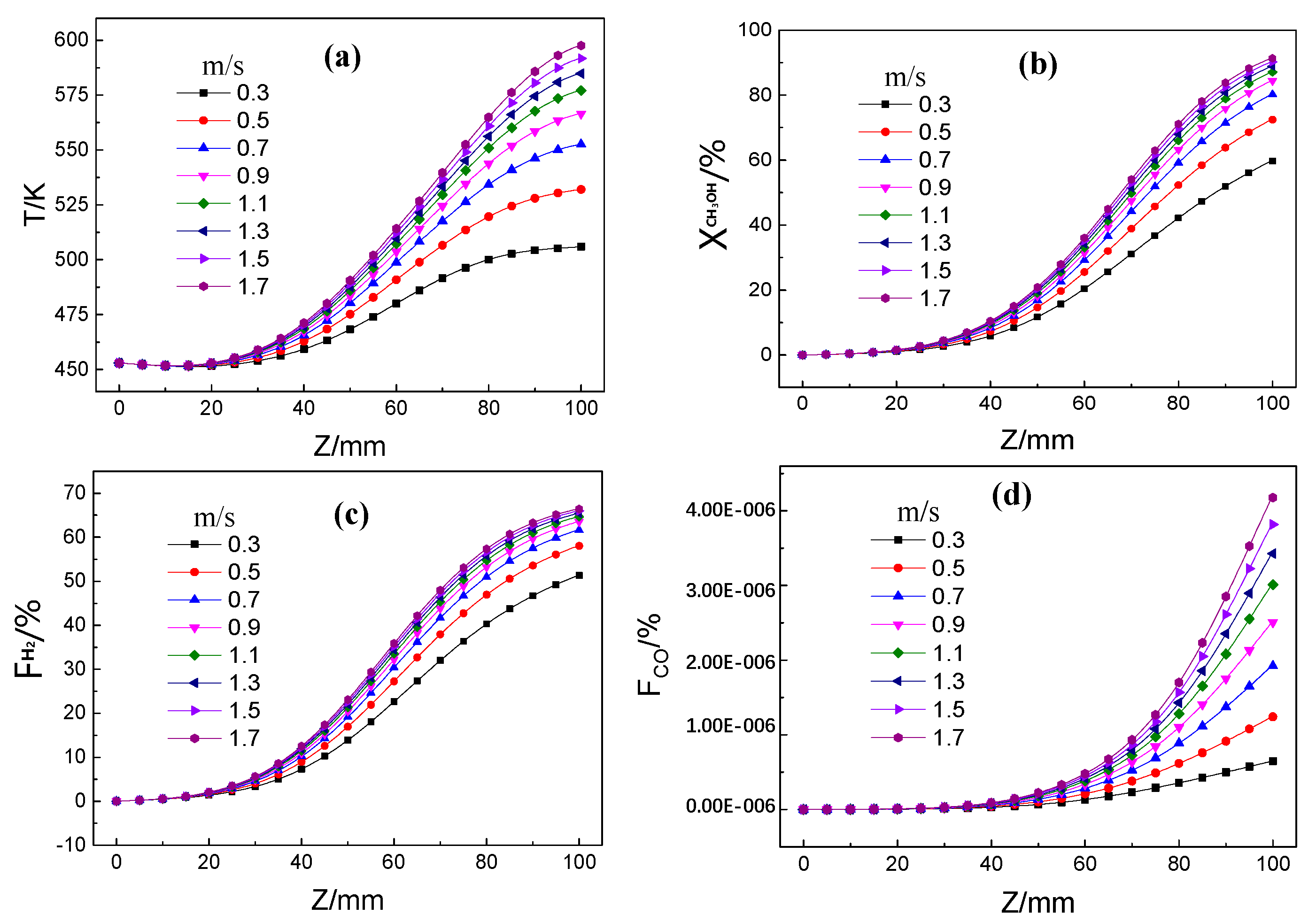
At inlet reactant temperature of 453 K, inlet reactant velocity of 0.1 m/s and inlet exhaust temperature of 673 K, the characteristics of the MSR are shown as figures when the inlet exhaust velocity increases from 0.3 m/s to 1.9 m/s. Figure 3a–d shows the temperature distribution, methanol conversion, and hydrogen and carbon monoxide in the direction of the central axis on the reaction side, when the inlet velocity of the exhaust increases from 0.3 m/s to 1.7 m/s. As can be seen from the figure, the temperature, methanol conversion, the hydrogen mole fraction along the axis all increase gradually with inlet exhaust velocity. The results agree with the literatures [27,37], and suitable for heterogeneous catalytic hydrogen production from MSR in microreactor. This is because the total amount of heat supplied to MSR increases as the inlet exhaust velocity increases, so the temperature of MSR increases. Since the MSR is endothermic, the methanol conversion increases. The temperature is lower at the front section on the reaction side due to the lower inlet temperature of the reactants. With the increase of the temperature in the axial direction, the MSR is favored, and the reaction intensity increases initially and decreases afterwards, along the axis. The axial temperature does not change much before 30 mm from the inlet, and then increases gradually. The hydrogen molar fraction increases slightly before 30 mm, is comparatively larger from 30 mm to 85 mm, and tends to be gentle after 85 mm. Before 80 mm, the molar fraction of carbon monoxide increases slowly with the inlet exhaust velocity and increases at a higher rate, from 80 mm to 100 mm. The same is the trend of the hydrogen mole fraction, as the methanol conversion increases at 30 mm from the inlet and then flattens.
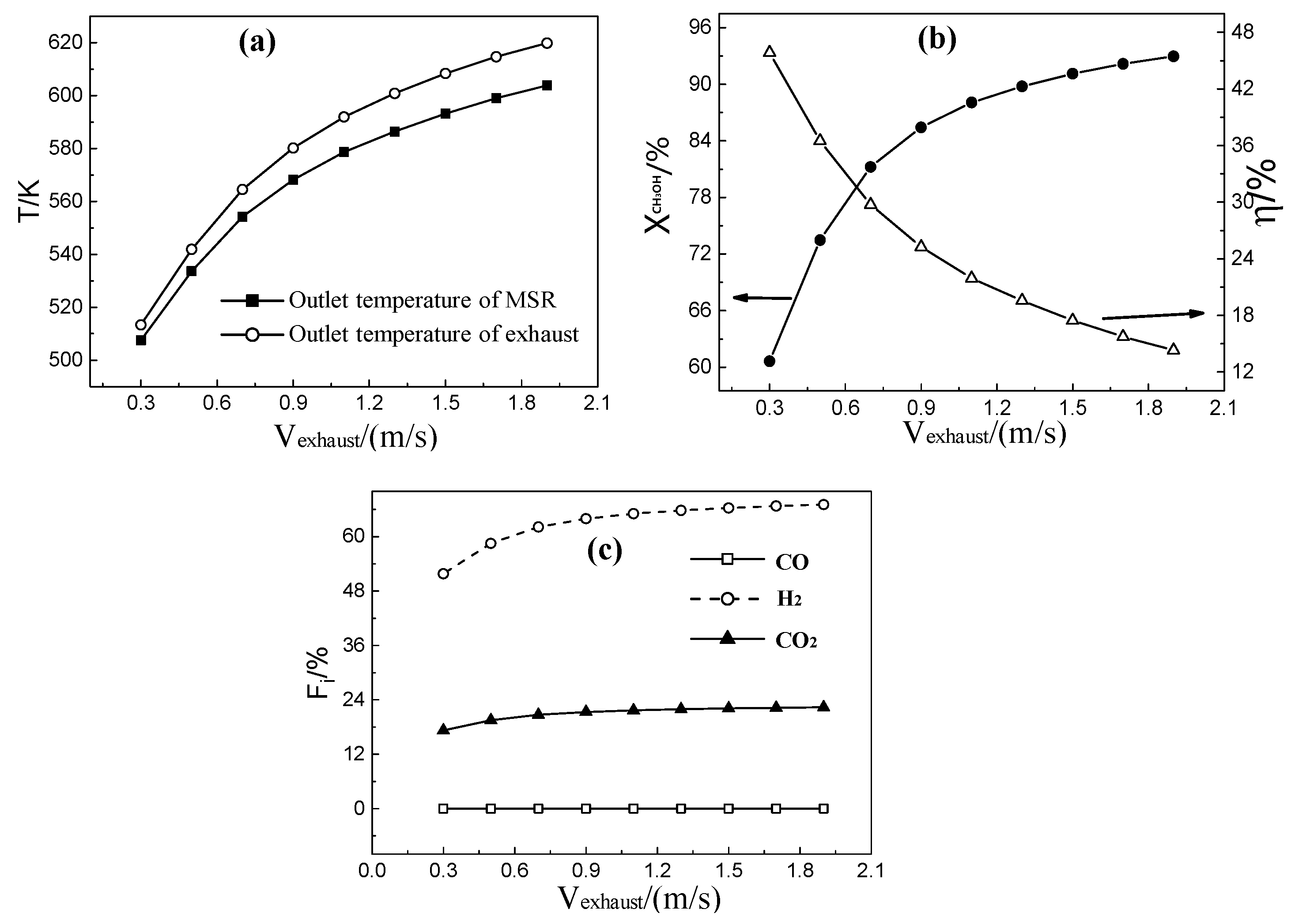
Figure 4a shows the outlet temperature change with the inlet exhaust velocity. With an increase in the inlet exhaust velocity, the outlet temperature of the MSR and the exhaust, and the temperature difference between the MSR and the exhaust increases. The outlet exhaust temperature is always higher than that of MSR. This is because the increase of the inlet exhaust velocity leads to a direct export of some heat, without participating in the MSR. Therefore, the outlet exhaust temperature becomes higher. As shown in Figure 4b, there is an increase in methanol conversion and thermal efficiency as the inlet exhaust velocity increases. This is because the heat absorption from the exhaust increases with an increase in the inlet exhaust velocity, and the methanol conversion. The increase of the outlet exhaust velocity leads to an increase in the output heat and a decrease in the thermal efficiency. As shown in Figure 4c, an increase in the methanol conversion causes an increase of the product, so the mole fraction of hydrogen, carbon monoxide, and carbon dioxide also increases with the increase of the inlet exhaust velocity. When the inlet exhaust velocity is lower than 1.1 m/s, the product increases with the increasing of inlet exhaust velocity, and then tends to be stable. This is consistent with the change trend of the methanol conversion and thermal efficiency. The highest efficiency is achieved when the inlet exhaust is 1.1 m/s, and a methanol conversion and waste heat utilization ratio of 88.07% and 21.93% is obtained, respectively.
3.2. Effects of Inlet Exhaust Temperature on MSR
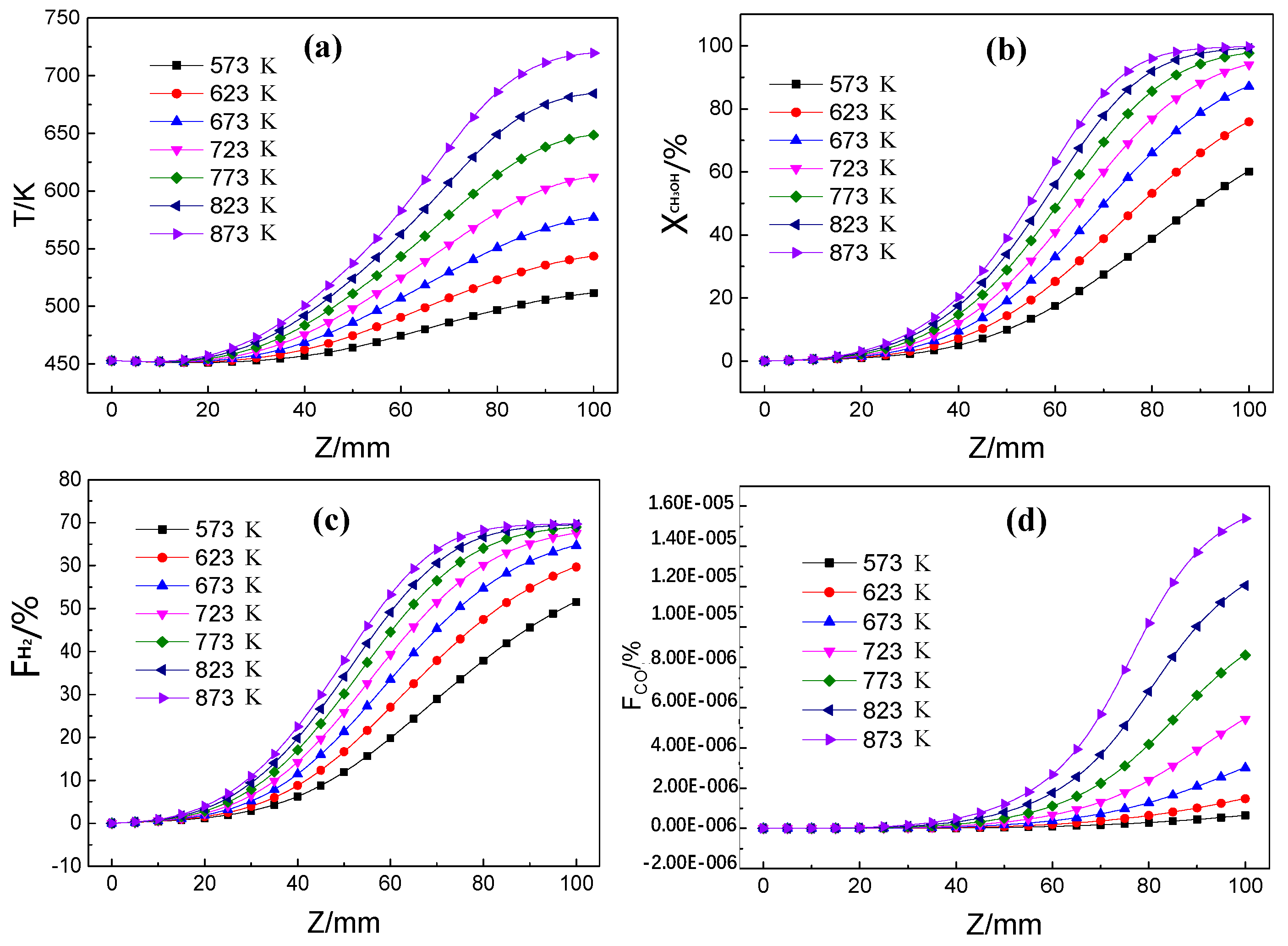
At inlet reactant temperature of 453 K, inlet reactant velocity of 0.1 m/s and inlet exhaust velocity of 0.1 m/s, the characteristics of the MSR are studied when the inlet exhaust temperature increases from 573 K to 873 K. Figure 5a shows the axial temperature distribution at different inlet exhaust temperatures. As the inlet exhaust temperature increases, the heat from the exhaust to MSR increases, so the axial temperature increases. The results also agree with the literatures [37]. The temperature of the reactants increases slowly before 20 mm, and then increases rapidly from 20 mm to 80 mm, and tends to be stable after 80 mm. Due to the low inlet temperature of the reactants, it needs to absorb the heat before reaching the reaction temperature, so the temperature at the front section of the entrance side is lower. As the reactant temperature increases, the MSR deepens, causing the amount of unreacted reactants to decrease. Consequently, the amount of heat absorption along the axial direction decreases, and the axial temperature increases gradually and tends to be stable. Figure 5b–d shows the axial distribution of methanol conversion, and hydrogen and carbon monoxide mole fraction, with different inlet exhaust temperature. All of these increase with an increase of the inlet exhaust temperature and increases gradually along the axis. It can be seen that the hydrogen mole fraction changes little before 18 mm and then increases gradually. When the inlet exhaust temperature is greater than 773 K, it stabilizes at about 80 mm from the entrance. This is because the reaction is almost completed at the position of about 80 mm when the exhaust temperature is 773 K, so the amount of the product changes little. Since hydrogen is the main product of the MSR, the change trends of the hydrogen and methanol conversion are similar. The molar fraction of carbon monoxide is almost 0 before 30 mm, and increases gradually after 30 mm. This is because the temperature is lower than that of methanol decomposition, 30 mm before the entrance.
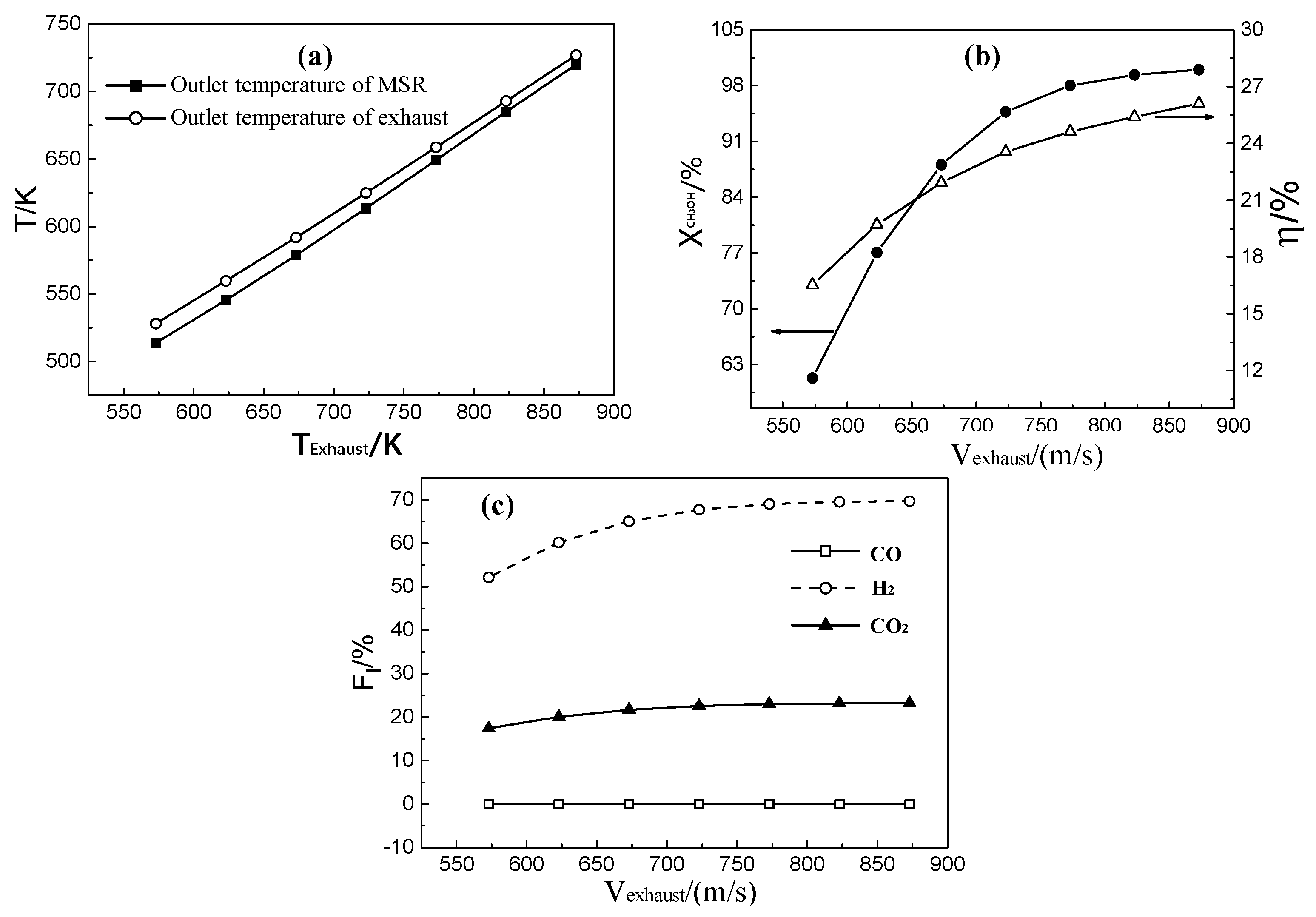
As shown in Figure 6a, the outlet temperature of the reactant and the exhaust increases with the inlet exhaust temperature. The higher the inlet exhaust temperature, the smaller the outlet temperature difference between the reactant and the exhaust, which decreases from 14.2 K to 6.88 K. The main reason is that the inlet exhaust temperature increase causes the heat absorbed to increase, and the main reaction section of the MSR moves parallel. In the latter part of the reaction side, the heat absorbed by the reactant is mainly used to raise the temperature of the reactant rather than supplying to the reaction. This leads to the outlet temperature rise. Figure 6b shows the change of thermal efficiency and methanol conversion with the inlet exhaust temperature. The methanol conversion increases from 61% to 99.9% and the thermal efficiency increases from 16% to 26%, with the inlet exhaust temperature. This is because the heat absorbed by the reactant increases with the increase of the inlet exhaust temperature, causing the methanol conversion to increase, as a result, more heat is utilized and the resulting thermal efficiency is higher. When the exhaust temperature is higher than 773 K, the increase of methanol conversion and thermal efficiency increases slowly. Since the heat increase caused by the inlet exhaust temperature is not supplied to MSR, the impact of the increase of the exhaust temperature on the MSR reaction becomes weak. Figure 6c shows the change of the mole fraction of the reaction product with the exhaust temperature. The products have the same change tendency, as the methanol conversion increases with the exhaust temperature. Therefore, when the inlet exhaust is 773 K, the best performance is achieved. At this time, the methanol conversion is 98%, the thermal utilization is 24.6%, and the mole fraction of hydrogen is 69%.
3.3. Effects of Reactant Inlet Velocity on MSR
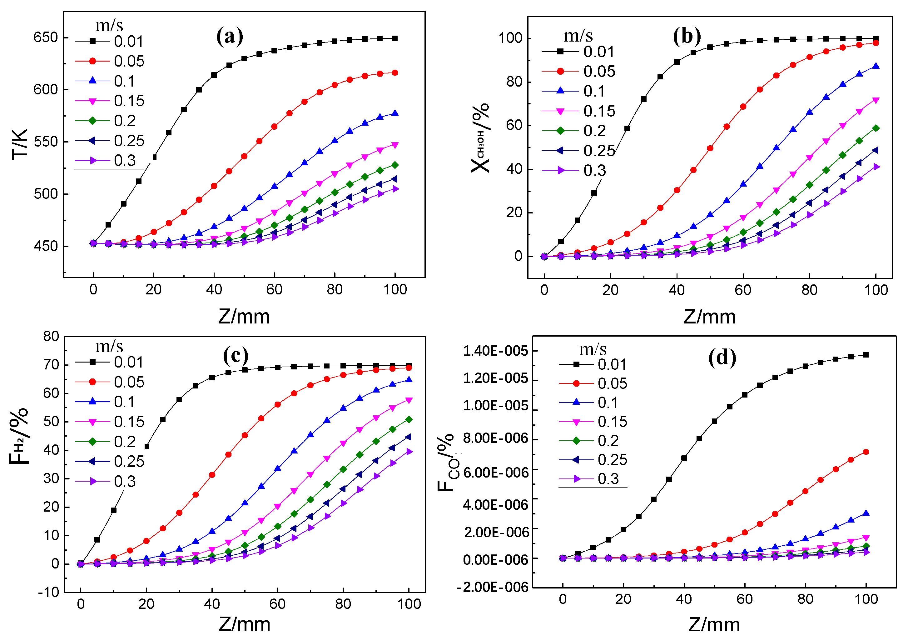
The characteristics of the MSR are studied when the inlet reactant velocity increases from 0.01 m/s to 0.3 m/s, at inlet exhaust velocity of 1.1 m/s, inlet exhaust temperature of 673 K, inlet reactant temperature of 453 K. As the inlet reactant velocity increases, the heat absorption by the reactant increases, resulting in a decrease of the temperature. The change laws agree with the literatures [37,38], but the increasing range is larger, because the temperature is higher than literature one. As shown in Figure 7a, the axial temperature increases gradually along the axis and decreases with the reactant inlet velocity. When the inlet reactant velocity is 0.01 m/s, the axial temperature increases rapidly and tends to stabilize at about 55 mm from the entrance. When the inlet reactants velocity is 0.05 m/s, the axial temperature tends to be stable at about 80 mm. When the inlet reactant velocity is more than 0.05 m/s, the axial temperature increases slowly, without being stable before the outlet. The heat supplied by the exhaust can meet the needs of the MSR with the inlet reactant velocity being less than 0.05 m/s, and the reaction starts at the entrance, with the temperature rising rapidly. When the heat supplied by the exhaust cannot satisfy the reaction with the inlet reactant velocity by more than 0.05 m/s, the reaction moves in the opposite direction and the reactant temperature side increases slowly. Figure 7b–d indicate the axial distribution of methanol conversion, hydrogen, and carbon monoxide, with the inlet reactant velocity. The methanol conversion, and the mole fractions of hydrogen and carbon monoxide decrease with the increase of inlet exhaust velocity and gradually increases along the axis. As can be seen from the figure, when the inlet velocity of the reactants are 0.01 m/s and 0.05 m/s, respectively, the methanol conversion and the mole fraction of hydrogen increases rapidly and become stable near the outlet. When the inlet velocity is greater than 0.05 m/s, the methanol conversion and the hydrogen mole fraction keep increasing along the axis. When the reactant inlet velocity is small, the heat supplied is sufficient for the MSR on the reaction side. Therefore, the methanol conversion and the products are already stable before the outlet. When the inlet reactant velocity increases, the heat absorption increases, resulting in the MSR moving in the opposite direction.
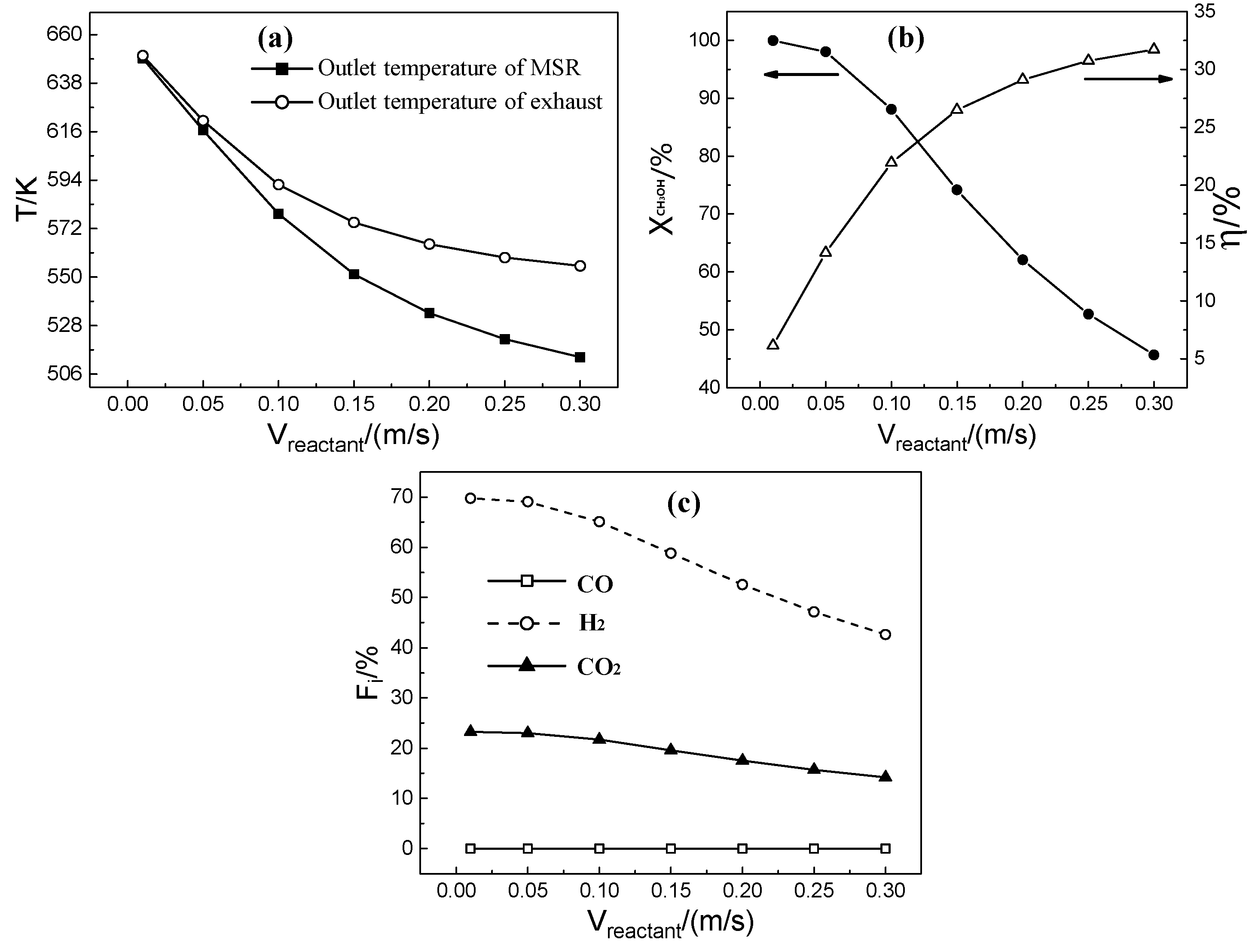
As shown in Figure 8a, when the reactant inlet velocity increases, the outlet temperature on the reactant and the exhaust decreases and the temperature difference between each other increases from 1 K to 41 K. At the constant amount of heat supplied from the exhaust, the heat required by the reactants increases when the reactant inlet velocity increases, so the outlet temperature decreases greatly. At this time, the heat is mainly used to supply the endothermic reaction. Moreover, the reactant temperature decreases with the increasing inlet reactant velocity. Figure 8b shows the change of the thermal efficiency and methanol conversion with the inlet reactant velocity. With the increase of the inlet reactant velocity, the thermal efficiency increases from 6% to 31.7%, and the methanol conversion decreases from 99.6% to 45.7%. This is because with the increase of the inlet velocity of the reactants, the contact time becomes shorter and the total heat cannot satisfy the heat absorbed, so the methanol conversion decreases. The thermal efficiency increase is caused by the increase of the temperature difference between the reactant and the exhaust. When the exhaust inlet velocity is 1.1 m/s, and the thermal efficiency is also considered, the reactant inlet velocity of 0.1 m/s is found to be optimal. Although methanol conversion is enhanced, the actual mass of hydrogen produced is indeed small at this condition, and the throughput can be increased by integrating a certain amount of rib microreactors. As shown in Figure 8c, the mole fractions of hydrogen, carbon monoxide, and carbon dioxide vary with the inlet velocity of the reactant. It indicates that the hydrogen mole fractions decreases with the increase of the inlet reactant velocity.
3.4. Effects of Reactant Inlet Temperature on MSR
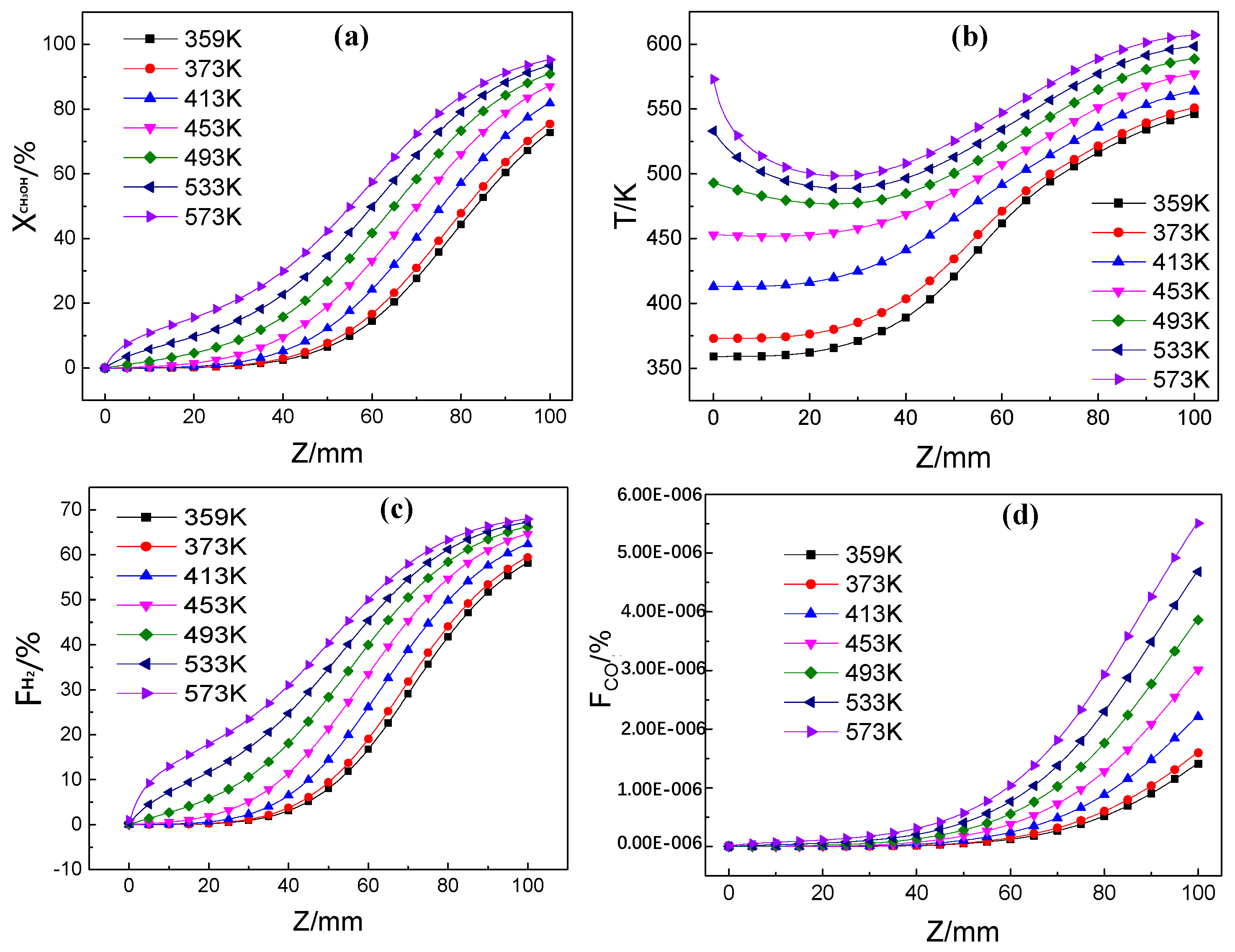
At inlet exhaust velocity of 1.1 m/s, temperature of 673 K and inlet reactant velocity of 0.1 m/s, the characteristics of the MSR are are illustrated in figures when the inlet reactant temperature increases from 359 K to 573 K. Figure 9a shows the axial temperature change with the inlet reactant temperature. The wall temperature on the reactant side increases as the inlet reactant temperature increases. When the inlet reactant temperature is higher than 493 K, the axial temperature begins to decrease, and then increases with the observed minimum temperature, at about 25mm. When the inlet reactant temperature is below 493 K, the axial temperature increases along the axis,, and increases slower after about 70 mm. At lower inlet reactant temperatures, the MSR reaction is relatively moderate without the temperature dropping significantly, and the “cold spot” appears at about 25 mm. At the lower inlet reactant temperature, the MSR reacts relatively gently without the temperature dropping significantly, so the “cold spot” is not observed.The “cold spot” temperature difference is smaller than that of the literature [28,29] because a microreator coupled with catalyst coating which has advantages of efficient heat transfer is adoptd in this study. Most of the reaction is completed at about 70 mm, after which the temperature increases rapidly. Figure 9b–d shows the axial distribution of methanol conversion and the mole fractions of hydrogen and carbon monoxide at different inlet temperatures.. It can be seen from the figure that the methanol conversion rate and the molar fraction of hydrogen and carbon monoxide gradually increase in the axial direction, and increase with the increase of the inlet reactant temperature. When the inlet reactant temperature is 533 K, the MSR reaction starts at the entrance. The main reason is that the heat carried by the reactants can reach MSR at a relatively high inlet reactant temperature, and absorbs a large amount of heat, which results in a “cold spot” at the entrance. In contrast, the MSR reaction is relatively gentle at lower inlet temperature. At this time, the methanol conversion and the mole fractions of hydrogen and carbon monoxide steadily increase along the axis.. The temperature of 359 K is the vaporization temperature of the reactants, and the reactants need to absorb heat.
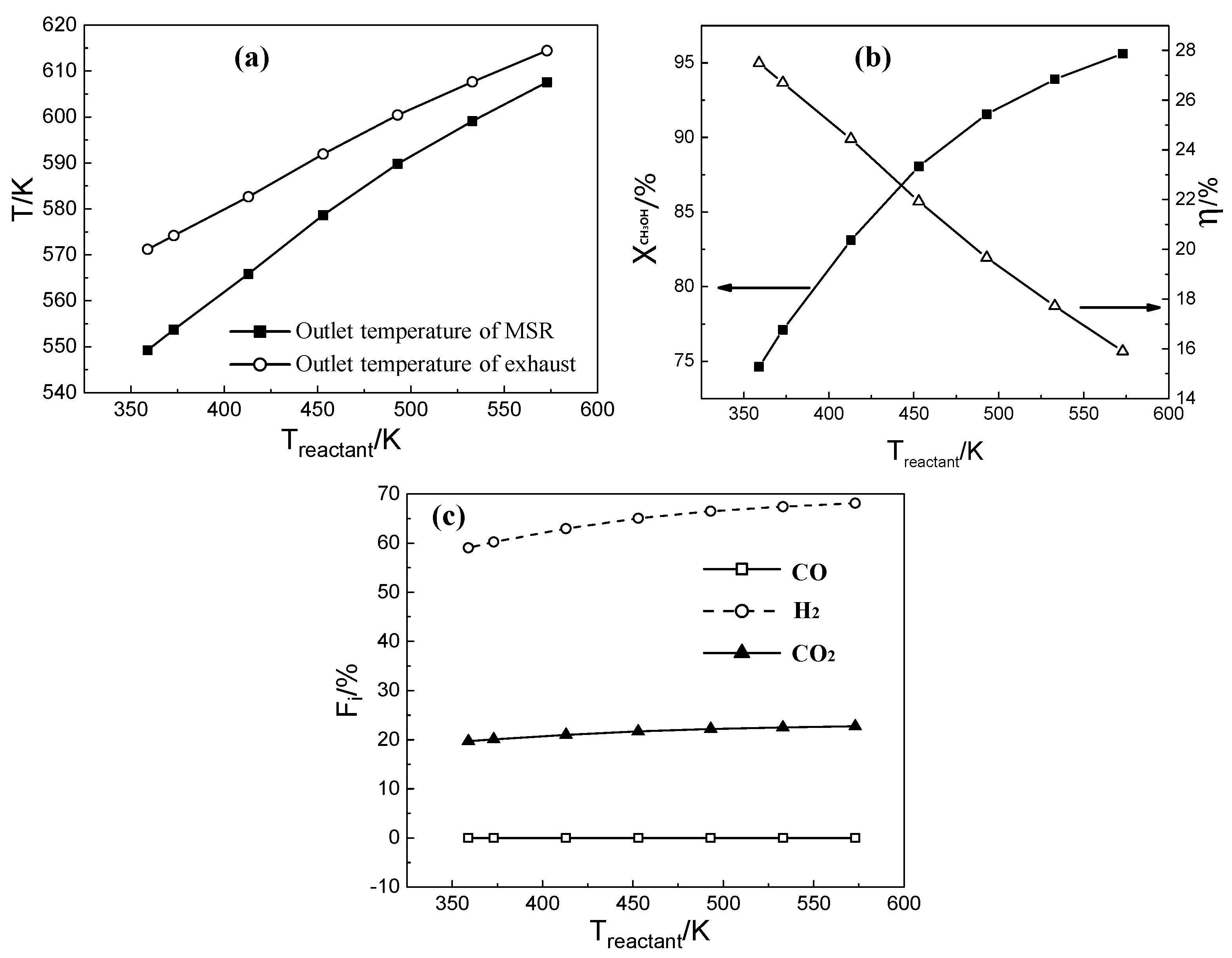
As the inlet temperature of the reactants increases, most of the reactions are completed before the outlet. At this time, the heat absorption from the exhaust reduces. Since the total amount of the exhaust is constant, the outlet temperature of the exhaust and the reaction side increases, and the temperature difference between the two sides decreases gradually. As shown in Figure 10a, the outlet temperature increases from 549 K to 607.5 K at the reaction side and the outlet temperature difference between the exhaust and the reaction side decreases from 21.9 K to 6.8 K.
Figure 10b is the change of the methanol conversion and the thermal efficiency with the reactant inlet temperature. As the reactant inlet temperature increases, the methanol conversion increases and the thermal efficiency decreases. When the inlet temperature is 359 K and 453 K, the methanol conversion is 74.5% and 88%, respectively. There is a big difference between the two conversions. The main reason is that the reaction temperature of the MSR based on the copper catalysts is higher than 359 K. The reactant is in a state of vaporization at a temperature of 359 K, and the temperature needs to be increased before the reaction. When the reactant inlet temperature is 453 K, the reactants react as soon as it contacts the catalyst, the methanol conversion increases and the thermal efficiency decreases. As shown in Figure 10c, the mole fraction of the product increases with the increasing inlet reactant temperature, and the hydrogen mole fraction increases from 59% to 68%.
3.5. Effects of W/A on MSR
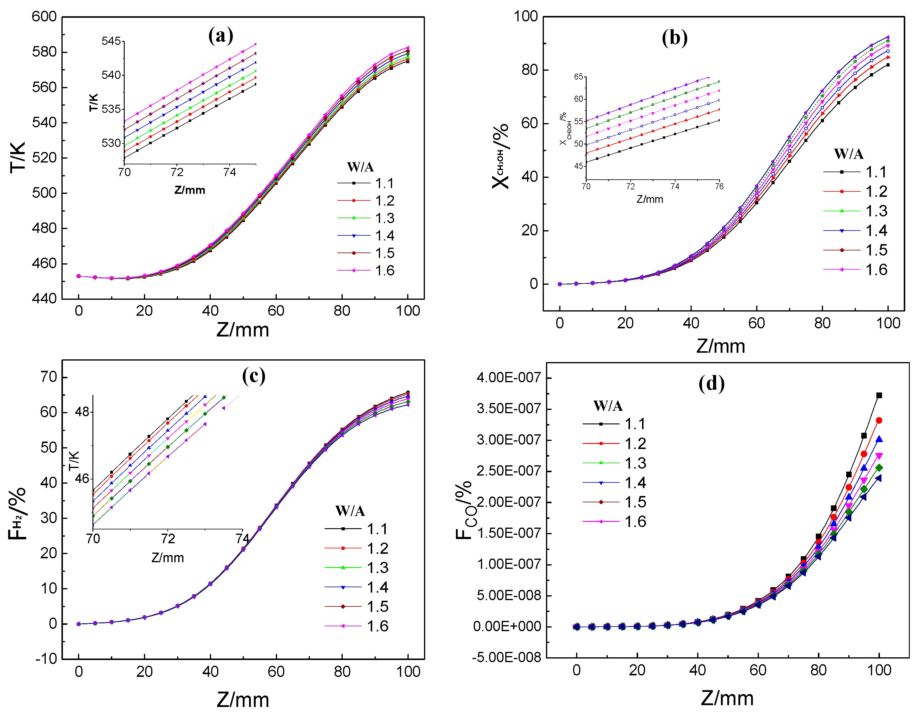
The characteristics of the MSR are shown as figures when the W/A increases from 1.1 to 1.6, at inlet reactant velocity of 0.1 m/s, temperature of 453 K and inlet exhaust velocity of 1.1 m/s. W/A (water-to-alcohol) indicates the molar ratio of water/methanol. Figure 11a shows the change of the axial temperature with the W/A. As can be seen from the figure, the axial temperature increases gradually with the increasing of W/A along the axis. When the W/A is 1.1 and 1.6, the outlet temperatures are 575 K and 582 K, respectively, with a little temperature difference observed. This indicates that W/A is not the most important factor for the MSR under the flow reaction conditions. The result agrees with the literature [33]. This is also confirmed by the change of the methanol conversion and the mole fractions of carbon monoxide and hydrogen with the W/A. As shown in Figure 11b–d, MSR does not start before about 25 mm, in all cases. This indicates that the heat is the main factor of influencing MSR. With the increase of W/A, the methanol conversion increases, as the methanol content in the unit mass of the reactant decreases at a constant heat. At the same time, as the total amount of reactant decreases, the products decrease and the mole fraction of hydrogen and carbon monoxide decreases as the W/A increases.
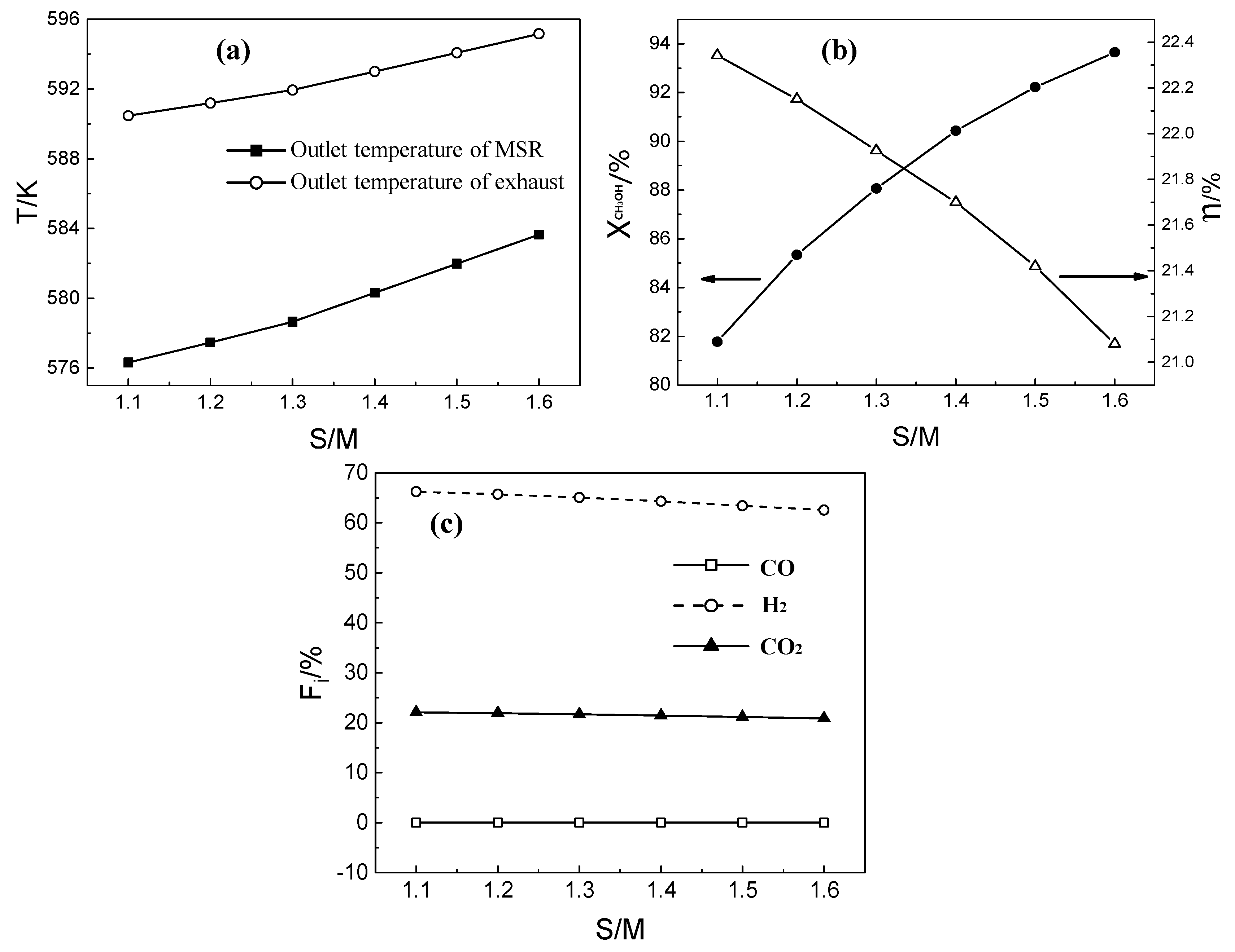
As shown in Figure 12a, the outlet temperature of the reaction and exhaust side increases with the increase of W/A. The temperature difference between the reaction and exhaust side does not change significantly while the maximum and the minimum temperature difference are 14.1 K and 11.4 K, respectively. This indicates that the change of the W/A has a slight effect on the MSR reaction. Simultaneously, it is verified that the heat is the main influencing factor at this time. Figure 12b shows the methanol conversion and thermal efficiency as a function of the W/A. The methanol conversion increases from 81.7% to 93.6% with the increase of W/A, and the thermal efficiency decreases from 22.3% to 21%. With the increase of the W/A, the MSR is conducive to hydrogen production, and the methanol conversion and hydrogen production rate increase. Sine water has a greater latent heat of vaporization and heat capacity, the increase of water content in the reactant leads to more heat consumption, which causes a drop in thermal efficiency. As shown in Figure 12c, the molar concentrations of carbon monoxide, hydrogen, and carbon dioxide decrease with increasinge W/A, and the optimal W/A in this work is 1.3.
3.6. Effects of Parallel and Counter Flow on MSR
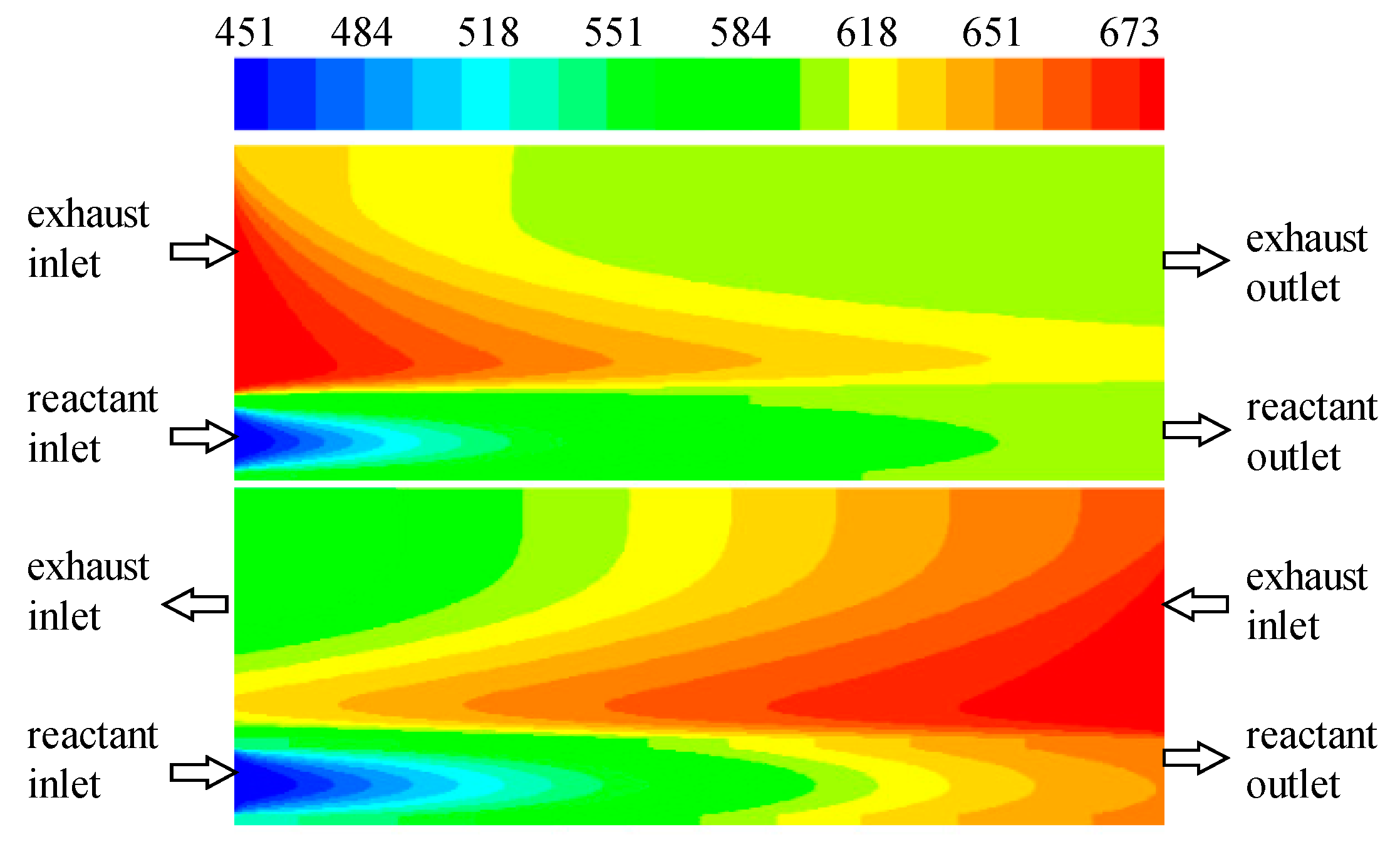
Figure 13 shows the temperature distribution of the parallel flow and counter flows when the inlet exhaust temperature is 773 K. Compared with the parallel flow, the temperature difference in the adjacent area of the reactor is smaller than that of the counter flow. The internal temperature increases on the reaction side, and the heat transferred from the exhaust to the MSR, increases.
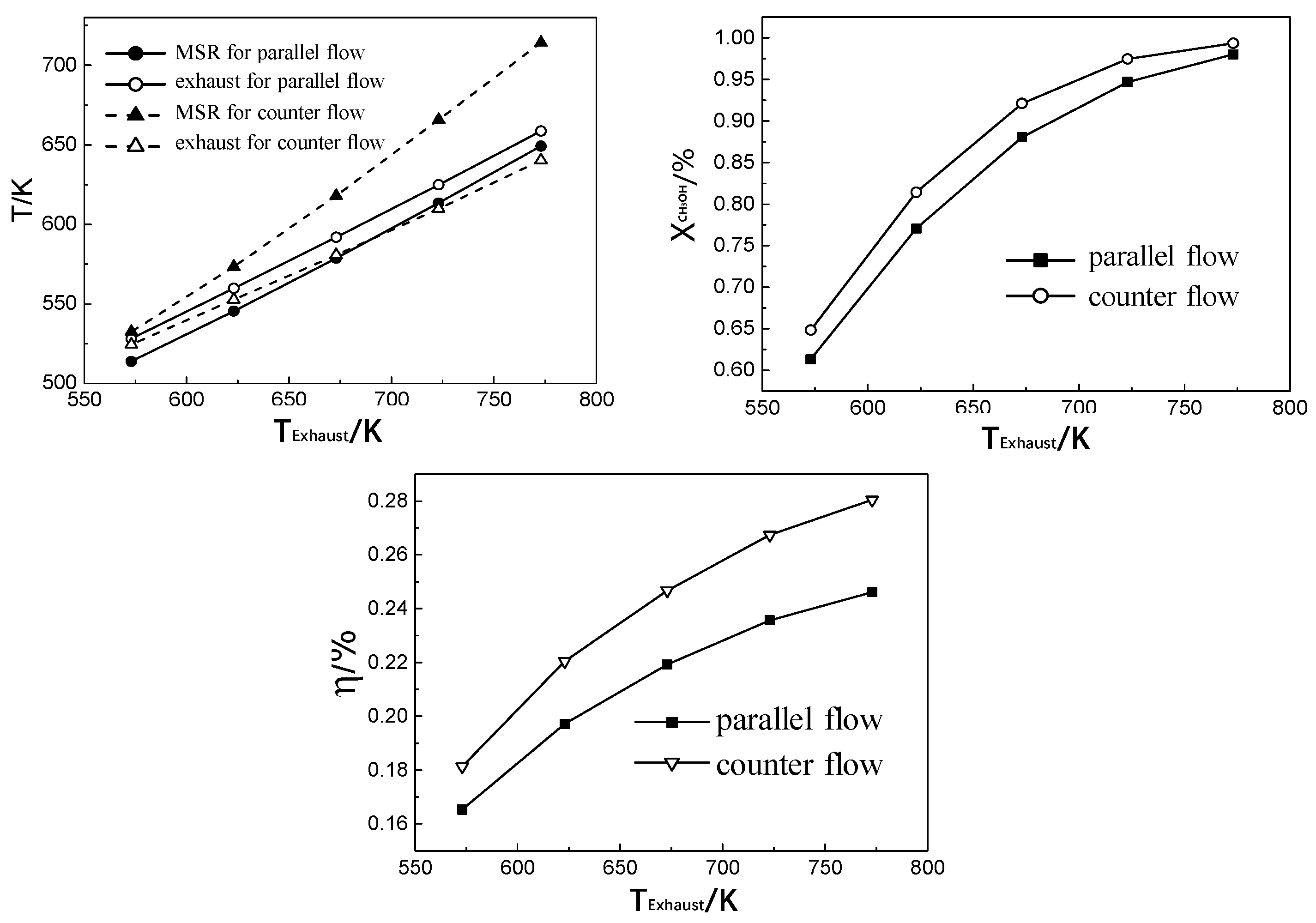
As shown in Figure 14a, the outlet temperatures on the reaction and the exhaust side increase along with increase of the inlet exhaust temperature, under the parallel and counter flow. At the parallel flow, the outlet temperature on the exhaust side is higher than that of the reaction side, and the outlet temperature difference decreases as the inlet exhaust temperature increases. At the parallel flow, the outlet temperature on the reaction side is higher than that of the exhaust side, and the temperature difference increases as the inlet exhaust temperature increases. At tehe parallel flow, the outlet of the exhaust is adjacent to the inlet of the lower temperature reactant, and the outlet of the reactants is adjacent to the inlet of high temperature exhaust, so the outlet temperature of reactants is higher than that of the exhaust. The heat supply of the exhaust is not enough for vigorous MSR in the front section, but the heat is sufficient in the rear section on the reaction side. However, for the parallel flow, the temperature of the reaction and the exhaust side both decrease as the reaction proceeds, so the outlet temperature on the reaction side is higher.
When the inlet temperature of the exhaust increases, the heat supplied to the reactant in the rear section increases. Meanwhile, the outlet reactant temperature and the temperature differencebothincrease. As shown in Figure 14b, the methanol conversion increases from 61% to 98% at parallel flow, and increases from 64.8% to 99% at counter flow. The methanol conversion of the counter flow was slightly higher than that of the parallel flow. This is possibly because the MSR is relatively gentle during the counter flow. There is some difference between this result and the literature [39]. The methanol conversion of the counter flow was higher than that of the parallel flow, often higher by 5%. This is probably because the model size of literature is larger than that of this study. The temperature difference between the exhaust and the reaction side is slightly larger in this study, causing a little more heat transfer amount. Therefore, methanol conversion and the thermal efficiency both increase slightly. As shown in Figure 14c, the thermal efficiency increases with an increase of the inlet exhaust temperature in the parallel and the counter flow. The thermal efficiency of the parallel flow increases from 16% to 24% and that of the counter flow increases from 18% to 28%. It can be known that the reactor performance is a little better at the counter flow.
4. Conclusions
A rib microreactor for MSR heated by automobile exhaust was designed to study the effects of inlet exhaust and methanol steam on the reactor performance. The results showed that the inlet temperature of the reactants is the most influential factor for MSR. The total amount of heat supplied to MSR increased as the inlet exhaust velocity increased. The methanol conversion and hydrogen mole along the axis all increased with the inlet exhaust velocity. Since the heat absorbed by the reactant increased with increasing inlet exhaust temperature, methanol conversion increased with increasing inlet exhaust temperature. The axial temperature increased gradually along the axis and decreased with the reactant inlet velocity. The methanol conversion, the mole fractions of hydrogen and carbon monoxide decreased with the increase of inlet exhaust velocity. The W/A slightly influenced the reactor performance of MSR. The best parameter performance of of MSR was observed with inlet exhaust velocity at 1.1 m/s, inlet exhaust temperature at 773 K, inlet reactant velocity at 0.1 m/s, inlet reactant temperature at 493 K, and W/A at 1.3, under counter flow. In addition, the methanol conversion of 99.4% was achieved with a thermal efficiency of 28%. Research results are beneficial for the developments of microreactor in comprehensive utilization of waste heat from heterogeneous catalytic reaction, and provides theoretical support for designing microreactor for waste heat utilization.
Author Contributions
Funding acquisition, F.W.; Investigation, G.W.; Methodology, F.W.; Project administration, F.W.; Visualization, G.W.; Writing—original draft, G.W.; Writing—review & editing, B.C. All authors have read and agreed to the published version of the manuscript.
Funding
This research was funded by the National Natural Science Foundation of China (50906104).
Acknowledgments
The authors acknowledge data sources supported by Yanyun Li.
Conflicts of Interest
The authors declare no conflict of interest.
References
- Han, J.; Liao, Y.; Zhang, J.; Wang, S.; Li, S. Target Fusion Detection of LiDAR and Camera Based on the Improved YOLO Algorithm. Mathematics 2018, 6, 213. [Google Scholar] [CrossRef] [Green Version]
- Driely, C.; Andrew, G. An Analysis of Children Left Unattended in Parked Motor Vehicles in Brazil. Int. J. Environ. Res. Public Health 2016, 13, 649. [Google Scholar]
- Feng-Hua, L.I.; Zhang, Y.J.; Zhang, J.; Yuan, Y.; Lin, W.U.; Mao, H.J. Characteristics of Particulate and Inorganic Elements of Motor Vehicles Based on a Tunnel Environment. Environ. Sci. 2018, 39, 1014–1022. [Google Scholar]
- Chen, T.Z.; Yan-Li, G.E.; Liu, Y.C.; Hong, H.E. VOCs Emission from Motor Vehicles in China and Its Impact on the Atmospheric Environment. Environ. Sci. 2018, 39, 478–492. [Google Scholar]
- Popescu, M.; Goss, J.; Staton, D.A.; Hawkins, D.; Chong, Y.C. Electrical Vehicles—Practical Solutions for Power Traction Motor Systems. IEEE Trans. Ind. Appl. 2018, 54, 2751–2762. [Google Scholar] [CrossRef] [Green Version]
- Llorca, C.; Angel-Domenech, A.; Agustin-Gomez, F.; Garcia, A. Motor vehicles overtaking cyclists on two-lane rural roads. Anal. Speed Lateral Clear. 2017, 92, 302–310. [Google Scholar]
- Pashchenko, D. Thermochemical waste-heat recuperation by steam methane reforming with flue gas addition. Int. J. Energy Res. 2019, 43, 2216–2226. [Google Scholar] [CrossRef]
- Deb, P.; Debnath, P.; Denis, A.F.; Lepcha, O.T. Variability of soil physicochemical properties at different agroecological zones of Himalayan region: Sikkim, India. Environ. Dev. Sustain. 2019, 21, 2321–2339. [Google Scholar] [CrossRef]
- Liu, Z.; Wang, J.; Zhang, T.; Zhou, S.; Yan, K. The effects of microbial fuel cells coupled with solar cells under intermittent illumination on sediment remediation. Environ. Sci. Process. Impacts 2019, 21, 2141–2149. [Google Scholar] [CrossRef] [PubMed]
- Wu, Y.; Jing, X.; Gao, C.; Huang, Q.; Cai, P. Recent advances in microbial electrochemical system for soil bioremediation. Chemosphere 2018, 211, 156–163. [Google Scholar] [CrossRef]
- Jung, G.; Chan, S.; Lai, C. Innovative membrane electrode assembly (MEA) fabrication for proton exchange membrane water electrolysis. Energies 2019, 12, 4218. [Google Scholar] [CrossRef] [Green Version]
- Prapinagsorn, W.; Sittijunda, S.; Reungsang, A. Co-digestion of napier grass and its silage with cow dung for bio-Hydrogen and methane production by two-stage anaerobic digestion process. Energies 2017, 11, 47. [Google Scholar] [CrossRef] [Green Version]
- Fang, L.; Li, Y.; Chen, S. Chemical looping hydrogen production using activated carbon and carbon black as multi-function carriers. Int. J. Hydrog. Energy 2018, 43, 5501–5511. [Google Scholar]
- Wang, R.; Ni, S.; Liu, G.; Xu, X. Hollow CaTiO3 cubes modified by La/Cr co-doping for efficient photocatalytic hydrogen production. Appl. Catal. B Environ. 2018, 225, 139–147. [Google Scholar] [CrossRef]
- Andrade, T.S.; Papagiannis, I.; Dracopoulos, V. Visible-light activated titania and its application to photoelectrocatalytic hydrogen peroxide. Materials 2019, 12, 4238. [Google Scholar] [CrossRef] [Green Version]
- Zhao, J.; Xuan, M.; Guan, X.; Qiang, W.; Wang, T. Investigation of hydrogen bubbles behavior in tungsten by high-flux hydrogen implantation. J. Nucl. Mater. 2018, 503, 198–204. [Google Scholar] [CrossRef]
- Pashchenko, D.I. Thermochemical recovery of heat contained in flue gases by means of bioethanol conversion. Therm. Eng. 2013, 60, 438–443. [Google Scholar] [CrossRef]
- Pashchenko, D.; Gnutikova, M.; Karpilov, I. Comparison study of thermochemical waste-heat recuperation by steam reforming of liquid biofuels. Int. J. Hydrog. Energy 2020, 45, 4174–4181. [Google Scholar] [CrossRef]
- Zhou, Y.; Tang, J.; Zhang, C. Thermodynamic analysis of the air-cooled transcortical Rankine cycle using CO2/R161 mixture based on natural draft dry cooling towers Thermodynamic analysis of the air-cooled transcritical Rankine cycle using CO2/R161 mixture based on natural draft dry cooling towers. Energies 2019, 12, 3342. [Google Scholar]
- Zhou, Y.; Li, Q.; Wang, Q. Energy Storage Analysis of UIO-66 and Water Mixed anofluids: An Experimental and Theoretical Study. Energies 2019, 12, 2521. [Google Scholar] [CrossRef] [Green Version]
- Feng, S.; Ping, W.; Yi, Z.; Wark, M.; Yang, J.; Wang, X. Construction of strontium tantalate homo-semiconductor composite photocatalysts with a tunable type II junction structure for overall water splitting. Catal. Sci. Technol. 2018, 8, 3025–3033. [Google Scholar]
- Su, S.; Zhang, L.; Zhang, Y.; Lei, J.; Pan, L. Thermodynamic simulation for hydrogen production in the methanol steam reforming system of kilowatt PEMFC. J. Petrochem. Univ. 2015, 28, 19–25. [Google Scholar]
- Zhang, Y.; Li, H.; Han, W.; Bai, W.; Yang, Y.; Yao, M.; Wang, Y. Improved design of supercritical CO2 Brayton cycle for coal-fired power plant. Energy 2018, 155, 1–14. [Google Scholar] [CrossRef]
- Goldmann, A.; Sauter, W.; Oettinger, M. A Study on Electrofuels in Aviation. Energies 2018, 11, 392. [Google Scholar] [CrossRef] [Green Version]
- Mishra, P.C.; Kar, S.K.; Mishra, H. Effect of perforation on exhaust performance of a turbo pipe type muffler using methanol and gasoline blended fuel: A step to NOx control. J. Clean. Prod. 2018, 183, 869–879. [Google Scholar] [CrossRef]
- Kumar, C.; Rana, K.B.; Tripathi, B. Effect of diesel-methanol-nitromethane blends combustion on VCR stationary CI engine performance and exhaust emissions. Environ. Sci. Pollut. Res. 2019, 26, 6517–6531. [Google Scholar] [CrossRef]
- Feng, W.; Cao, Y.; Wang, G. Thermoelectric generation coupling methanol steam reforming characteristic in microreactor. Energy 2014, 80, 642–653. [Google Scholar]
- Abdullah, N.; Bahruji, H.; Rogers, S.M.; Wells, P.P.; Catlow, C.R.A.; Bowker, M. Pd local structure and size correlations to the activity of Pd/TiO2 for photocatalytic reforming of methanol. Phys. Chem. Chem. Phys. 2019, 21, 16154–16160. [Google Scholar] [CrossRef] [Green Version]
- Nowicka, E.; Althahban, S.M.; Luo, Y.; Kriegel, R.; Hutchings, G.J. Highly selective PdZn/ZnO catalysts for the methanol steam reforming reaction. Catal. Sci. Technol. 2018, 8, 5848–5857. [Google Scholar] [CrossRef]
- Qing, S.; Hou, X.; Liu, Y.; Li, L.; Fan, W. Strategic use of CuAlO2 as a sustained release catalyst for production of hydrogen from methanol steam reforming. Chem. Commun. 2018, 54, 12242–12245. [Google Scholar] [CrossRef]
- Chen, B.; Wang, L.; Wang, F. Study on methane steam reforming coupling high-temperature exhaust heat utilization for hydrogen production. Int. J. Green Energy 2019, 16, 1–11. [Google Scholar] [CrossRef]
- Ngoenthong, N.; Hartley, M.; Sornchamni, T. Comparison of packed-bed and micro-channel reactors for hydrogen production via thermochemical cycles of water splitting in the presence of ceria-based catalysts. Processes 2019, 7, 767. [Google Scholar] [CrossRef] [Green Version]
- Zhou, W.; Ke, Y.; Pei, P.; Yu, W.; Chu, X.; Li, S.; Yang, K. Hydrogen production from cylindrical methanol steam reforming microreactor with porous Cu-Al fiber sintered felt. Int. J. Hydrog. Energy 2018, 43, 3643–3654. [Google Scholar] [CrossRef]
- Liang, Z.; Peng, G.; Tang, Z.; Min, L.; Sun, Y. Three dimensional porous Cu-Zn/Al foam monolithic catalyst for CO2 hydrogenation to methanol in microreactor. J. CO2 Util. 2017, 21, 191–199. [Google Scholar] [CrossRef]
- Pashchenko, D. Pressure drop in the thermochemical recuperators filled with the catalysts of various shapes_ A combined experimental and numerical investigation. Energies 2019, 166, 462–470. [Google Scholar] [CrossRef]
- Mardle, P.; Fernihough, O.; Du, S. Evaluation of the Scaffolding Effect of Pt Nanowires Supported on Reduced Graphene Oxide in PEMFC Electrodes. Coating 2018, 8, 48. [Google Scholar] [CrossRef] [Green Version]
- Liao, C.H.; Horng, R.F. Investigation on the hydrogen production by methanol steam reforming with engine exhaust heat recovery strategy. Int. J. Hydrogen Energy 2016, 41, 4957–4968. [Google Scholar] [CrossRef]
- Tripodi, A.; Compagnoni, M.; Martinazzo, R. Process simulation for the design and scale up of heterogeneous catalytic process: Kinetic modelling issues. Catalysts 2017, 7, 159. [Google Scholar] [CrossRef]
- Pickard, W.F.; Abraham-Shrauner, B. Simplified models of the symmetric single-pass parallel-plate counterflow heat exchanger: A tutorial. Roy Soc Open Sci 2018, 5, 171617. [Google Scholar] [CrossRef] [Green Version]
Figure 1.
Schematic diagram of rib reactor.

Figure 2.
Comparison of the experimental and simulation results.

Figure 3.
Temperature in the axial direction (a), methanol conversion (b), hydrogen mole fraction (c), and carbon monoxide mole fraction (d), as a function of inlet exhaust velocity.
Figure 3.
Temperature in the axial direction (a), methanol conversion (b), hydrogen mole fraction (c), and carbon monoxide mole fraction (d), as a function of inlet exhaust velocity.

Figure 4.
Outlet temperature on the reaction and exhaust side (a), methanol conversion and thermal efficiency (b), and reaction product mole fraction (c) as a function of inlet exhaust velocity.
Figure 4.
Outlet temperature on the reaction and exhaust side (a), methanol conversion and thermal efficiency (b), and reaction product mole fraction (c) as a function of inlet exhaust velocity.

Figure 5.
Axial temperature (a), methanol conversion (b), hydrogen mole fraction (c), carbon monoxide mole fraction (d), as a function of the exhaust temperature.
Figure 5.
Axial temperature (a), methanol conversion (b), hydrogen mole fraction (c), carbon monoxide mole fraction (d), as a function of the exhaust temperature.

Figure 6.
Outlet temperature of reactant and exhaust (a), methanol conversion and thermal efficiency (b), and mole fraction of the reaction product (c), as a function of inlet exhaust temperature.
Figure 6.
Outlet temperature of reactant and exhaust (a), methanol conversion and thermal efficiency (b), and mole fraction of the reaction product (c), as a function of inlet exhaust temperature.

Figure 7.
Temperature in the axial direction (a), methanol conversion (b), hydrogen mole fraction (c), and carbon monoxide mole fraction (d), as a function of reactant inlet velocity.
Figure 7.
Temperature in the axial direction (a), methanol conversion (b), hydrogen mole fraction (c), and carbon monoxide mole fraction (d), as a function of reactant inlet velocity.

Figure 8.
Outlet temperature of product and exhaust (a), methanol conversion and thermal efficiency (b), and mole fraction (c), as a function of reactant inlet velocity.
Figure 8.
Outlet temperature of product and exhaust (a), methanol conversion and thermal efficiency (b), and mole fraction (c), as a function of reactant inlet velocity.

Figure 9.
Temperature along the axial direction(a), methanol conversion (b), hydrogen mole fraction (c), and carbon monoxide mole fraction (d), as a function of reactant inlet temperature.
Figure 9.
Temperature along the axial direction(a), methanol conversion (b), hydrogen mole fraction (c), and carbon monoxide mole fraction (d), as a function of reactant inlet temperature.

Figure 10.
Outlet temperatures of the reaction side and the exhaust side (a), methanol conversion and thermal efficiency (b), and product mole fraction (c), as a function of reactant inlet temperature.
Figure 10.
Outlet temperatures of the reaction side and the exhaust side (a), methanol conversion and thermal efficiency (b), and product mole fraction (c), as a function of reactant inlet temperature.

Figure 11.
Axial temperature (a), methanol conversion (b), hydrogen mole fraction (c), and carbon monoxide mole fraction (d) as a function of water-to-alcohol (W/A).
Figure 11.
Axial temperature (a), methanol conversion (b), hydrogen mole fraction (c), and carbon monoxide mole fraction (d) as a function of water-to-alcohol (W/A).

Figure 12.
Outlet temperature on the reaction and exhaust side (a), methanol conversion and thermal efficiency (b), and mole fraction of reaction product (c), as a function of the W/A.
Figure 12.
Outlet temperature on the reaction and exhaust side (a), methanol conversion and thermal efficiency (b), and mole fraction of reaction product (c), as a function of the W/A.

Figure 13.
Temperature map of parallel and counter flow.

Figure 14.
Outlet temperature of the methanol steam reforming (MSR) and the exhaust (a), methanol conversion (b), and the thermal efficiency (c), with inlet exhaust temperature under different inlet exhaust temperatures.
Figure 14.
Outlet temperature of the methanol steam reforming (MSR) and the exhaust (a), methanol conversion (b), and the thermal efficiency (c), with inlet exhaust temperature under different inlet exhaust temperatures.

© 2020 by the authors. Licensee MDPI, Basel, Switzerland. This article is an open access article distributed under the terms and conditions of the Creative Commons Attribution (CC BY) license (http://creativecommons.org/licenses/by/4.0/).
Share and Cite
MDPI and ACS Style
Wang, G.; Wang, F.; Chen, B. Performance Study on Methanol Steam Reforming Rib Micro-Reactor with Waste Heat Recovery. Energies 2020, 13, 1564. https://doi.org/10.3390/en13071564
AMA Style
Wang G, Wang F, Chen B. Performance Study on Methanol Steam Reforming Rib Micro-Reactor with Waste Heat Recovery. Energies. 2020; 13(7):1564. https://doi.org/10.3390/en13071564
Chicago/Turabian StyleWang, Guoqiang, Feng Wang, and Bohong Chen. 2020. "Performance Study on Methanol Steam Reforming Rib Micro-Reactor with Waste Heat Recovery" Energies 13, no. 7: 1564. https://doi.org/10.3390/en13071564
Note that from the first issue of 2016, this journal uses article numbers instead of page numbers. See further details here.